pneumatic/hydraulic blind riveting tool accessory kit chr2202 ... · the tool‘s hydraulic system,...
TRANSCRIPT
Art.-No. CHR2302
Translation of the original instructions
Pneumatic/hydraulic blind riveting tool
Accessory kit CHR2202
Instruction Manual

2

3
This instruction manual is protected by copyright. No use outwith the strict limitations of copyright legislation wit-hout the consent of the manufacturer is permitted, this rendering the offender liable to criminal prosecution. This applies likewise for the extraction of individual illustrations and the use of texts in extract form.
Chapter Page
Safety
1.1 Information regarding this manual 4
1.2 Explanation of symbols 4
1.3 Markings 5
Scope of supply
2.1 Operating principles 5
2.2 Scope of supply and accessories 6
2.3 Technical Specifications 6
2.4 Safety instructions 7
2.5 Working with the blind riveting tool - basic principles 8
2.6 Maintenance 9
2.7 Warranty 10
Technical data
3.1 Technical data 11
Startup
4.1 Preparing the operating unit 12
4.2 Preparing the pressure generator and connecting to the operating unit 13
4.3 Connecting up the blind riveting tool and operating unit 14
4.4 Safe set-up and Positioning of equipment 15
Application
5.1 Fitting blind rivets 16
5.2 Emptying the mandrel collector 17
5.3 Fitting the ejector 18
5.4 Replacing conical grips 19
5.5 Maintenance and cleaning 20
5.6 Completing an operation and riveting tool storage 21
Service
6.1 Troubleshooting 22
6.2 Spare parts 24
6.3 Components 24
6.4 Disposal 26
6.5 Liability 26
6.6 Declaration of Conformity 27
1.
2.
3.4.
5.
6.
Accessories and spare parts:http://www.chiefautomotive.com
4
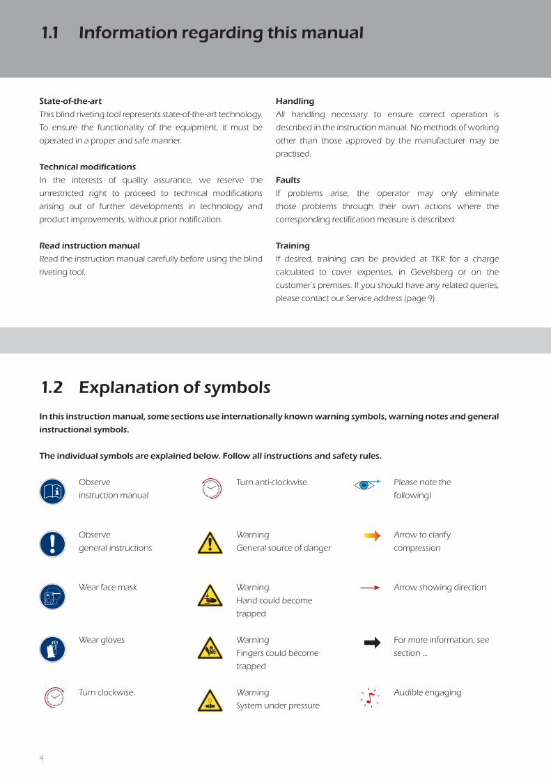
Observe
instruction manual
Observe
general instructions
Wear face mask
Wear gloves
Turn clockwise.
1.2 Explanation of symbols
In this instruction manual, some sections use internationally known warning symbols, warning notes and general
instructional symbols.
The individual symbols are explained below. Follow all instructions and safety rules.
Turn anti-clockwise.
Warning
General source of danger
Warning
Hand could become
trapped
Warning
Fingers could become
trapped
Warning
System under pressure
Please note the
following!
Arrow to clarify
compression
Arrow showing direction
For more information, see
section …
Audible engaging
State-of-the-art
This blind riveting tool represents state-of-the-art technology.
To ensure the functionality of the equipment, it must be
operated in a proper and safe manner.
Technical modifications
In the interests of quality assurance, we reserve the
unrestricted right to proceed to technical modifications
arising out of further developments in technology and
product improvements, without prior notification.
Read instruction manual
Read the instruction manual carefully before using the blind
riveting tool.
Handling
All handling necessary to ensure correct operation is
described in the instruction manual. No methods of working
other than those approved by the manufacturer may be
practised.
Faults
If problems arise, the operator may only eliminate
those problems through their own actions where the
corresponding rectification measure is described.
Training
If desired, training can be provided at TKR for a charge
calculated to cover expenses, in Gevelsberg or on the
customer‘s premises. If you should have any related queries,
please contact our Service address (page 9).
1.1 Information regarding this manual

5
1.3.1
ACD
E
1.3.2 1.3.3
B
A Serial number
B CE marking
C Production date
D Manufacturer‘s
identification
Markings on the blind riveting tool
E Warnings (for complete
view see Fig. 1.3.3)
2.1 Operating principles
The pneumatic/hydraulic blind riveting tool has been
specially developed for all common riveting operations on
thin sheet metal.
The scope of supply covers the blind riveting tool with
operating unit and the hose package.
The blind riveting tool may be used exclusively
with the PNP 90 hydraulic pump.
The hydraulic pump is a pneumatically driven pressure
intensifier with a pressure ratio of 1:100. This means that a
hydraulic output pressure of 600 bars is generated with an
input air pressure of 6 bars. When the equipment‘s preset
final pressure is reached, the pump stops automatically and
keeps this pressure constant. The hydraulic pump has a
pneumatically controlled pressure relief valve.
The blind riveting tool is connected to the hydraulic pump via
a high-pressure hose. The hose is connected to the pump via
a leak-free quick release coupling. The coupling can only be
connected to the equipment when it is depressurised.
The two pneumatic control lines are also connected to the
pump. Make sure that the black and the blue hoses are
inserted into the couplings with the relevant markings.
Compressed air can be connected to the
equipment as soon as the hydraulic hose
and the control lines are connected to the
pump.
The operating unit is provided with an actuating lever behind
a trigger guard.
If the valve is activated, the pump begins to run and the
hydraulic plunger extends.
If the operating lever is released, the pump is deactivated and
the hydraulic plunger retracts to its original position.
1.3 Designations
ACD
B

6
2.3 Technical specifications
Travel 20 mm
Setting force 24500 N at 6 bar
Weight 0.8 kg (without hose and operating unit)
Hydraulic operating pressure max. 600 bar
Pneumatic operating pressure 6 bar
Ambient temperature 5–50 °C / 41 –122 °F
Prescribed safety clothingProtective gloves, eye protection, long-sleeved working
clothes, close fitting at the neck
Drive unit PNP 90 hydraulic pump
Vibration emission value a < 2,5 m/s²
2.2 Scope of supply and accessories
®
Pneumatisch hydraulisches
Blindniet-Werkzeug
Bedienungsanleitung
505002
Originalbedienungsanleitung /
Translation of the original instructions
Pneumatic/hydraulic
blind riveting tool
Instruction Manual
Art.-No. CHR???
Translation of the original instructions
Pneumatic/hydraulic
blind riveting tool
Instruction Manual
1 x operating unit1 x toolbox
2 x assembly spanners
1 x blind riveting tool with
mandrel collector
Instruction Manual1-part conical grip set 4.2 mm
* Ø 4.2 mm
* * Blind rivets not included

7
The hydraulic tool kit is is approved exclusively for
the purposes intended by the manufacturer.
Only genuine accessories may be used. Use of
non-genuine tools or accessories presents a major
safety hazard.
Do not use any hoses or fittings that are not
permitted for the equipment's operating pressure.
Ensure that only trained and instructed personnel
use the equipment!
Use of the equipment by persons who have not
been instructed in its use is prohibited.
Ensure that the instruction manual is made
available to operating personnel.
Protective gloves and a face mask must strictly
be worn for all applications of the equipment,
because metallic parts can break up and fly off
with great force if the tool is faulty or operated
incorrectly. Work clothing should also be long-
sleeved and close fitting around the neck.
As a result, there is a risk of severe bodily injury!
See also ANSI Z87.1-1989.
Observe the applicable national regulations for
prevention of accidents.
Before any use is made of the tool, a visual surface
check must be carried out - no deep scratches
must be visible.
Never operate the tool without the rear closing
cap in place.
Before use, check seals for any oil leaks.
Before use, check the threaded connection on the
piston to ensure it is firmly seated and manually
tighten as required.
Never throw the tool or allow it to fall. Never
misuse the tool or lend it to untrained personnel.
The tool must only be used in ambient temperatures
of above 5 °C and at a maximum of 50 °C.
The tool must never be used in potentially
explosive areas.
You must read and understand the safety
instructions before setting up, operating,
repairing or maintaining the machine or replacing
accessories on it and before working near the
machine for non-threaded fasteners. Not reading
the instructions may result in serious bodily injury.
This machine for non-threaded fasteners must
not be modified. Modifications may reduce the
effectiveness of safety equipment and increase
operator risk.
If the machine for non-threaded fasteners is
damaged, you must not use it.
If any abnormality is identified, the tool must not be used.
Please contact Service.
2.4 Safety instructions

8
Risk of injury
Route all supply lines in a manner that prevents
people from tripping over them. Correctly
route and attach the compressed air hose. If a
compressed air hose whips around wildly, it could
cause severe bodily injury.
Before starting work, check the preset air
pressure! Incorrectly set air pressure could
cause equipment damage or bodily injury!
Max. air pressure
Make sure that the maximum permissible
operating air pressure of 6 bar / 87 psi is never
exceeded. Check the setting of the pressure
regulating valve before each riveting operation!
Clean compressed air
Make sure that the pump is only supplied
with clean and dry compressed air. Moisture
and contamination could cause equipment
malfunction and/or damage. Only use
compressed air of quality class 2 as per ISO 8573-1.
Always disconnect the blind riveting tool
from the compressed air when leaving your
work station!
Warranty
The manufacturer accepts no liability for damage
or injury caused by improper repair or use of non-
original replacement parts.
Incorrect usage of the blind riveting tool that leads
to equipment damage invalidates the warranty.
The compressed air supply must be
disconnected from the equipment before
any adjustment or maintenance work is
performed.
2.5 Working with the blind riveting tool - basic principles

9
The tool‘s hydraulic system, pneumatic
control systems, hoses and couplings must all
be kept free of dirt and other contamination.
Foreign bodies in the hydraulic fluid or in
the control air will cause the tool system to
malfunction.
All maintenance and service work on the
blind riveting tool must only be performed
with the pump disconnected.
Under normal circumstances, maintenance of the
blind riveting tool is restricted to regular cleaning
and replacement of the conical grips.
All other necessary maintenance work and/or
repairs must be performed by the manufacturer
or properly trained personnel only.
The user must only perform the maintenance
and repair measures outlined in this instruction
manual.
5.5
Maintenance and repair work not covered in this
instruction manual may only be performed by
professionals with proper training by VSG. For
further information on servicing and training,
please contact us at our Service address:
Chief Automotive Technologies
Service
996 Industrial Drive
Madison, IN 47250
Phone: 800-445-9262
Fax: 866-275-0173
Accessories and spare parts:http://www.chiefautomotive.com
2.6 Maintenance

10
Blind riveting tools from Chief Automotive Technologies come with a 12-month warranty against material and manufacturing defects.
This does not cover wearing parts (rivet mandrels, rivet dies, spacing bolts and spa-cing sleeves) or hydraulic oil.
The warranty period begins on the date of delivery, as specified on the invoice or delivery note.
The warranty is valid for the user/customer provided that the tool is obtained from an authorized sales outlet and is used as described in the instructions and for the purposes for which it was designed. The warranty becomes invalid if the tool is used for purposes other than those for which it was designed.In addition, the warranty becomes invalid if the tool is not used as described in the instruction manual.
In the event of defect or fault, Chief Automotive Technologies will only repair or re-place faulty parts at its own discretion.
Your supplier and service partner: Chief Automotive Technologies
Service
996 Industrial Drive
Madison, IN 47250
Phone: 800-445-9262
Fax: 866-275-0173
Accessories and spare parts:http://www.chiefautomotive.com
2.7 Warranty
11
333
130
58
163
28O
164
62
37
3.1.1
3.1.2
127
37
62
1093.1.3
3.1.4
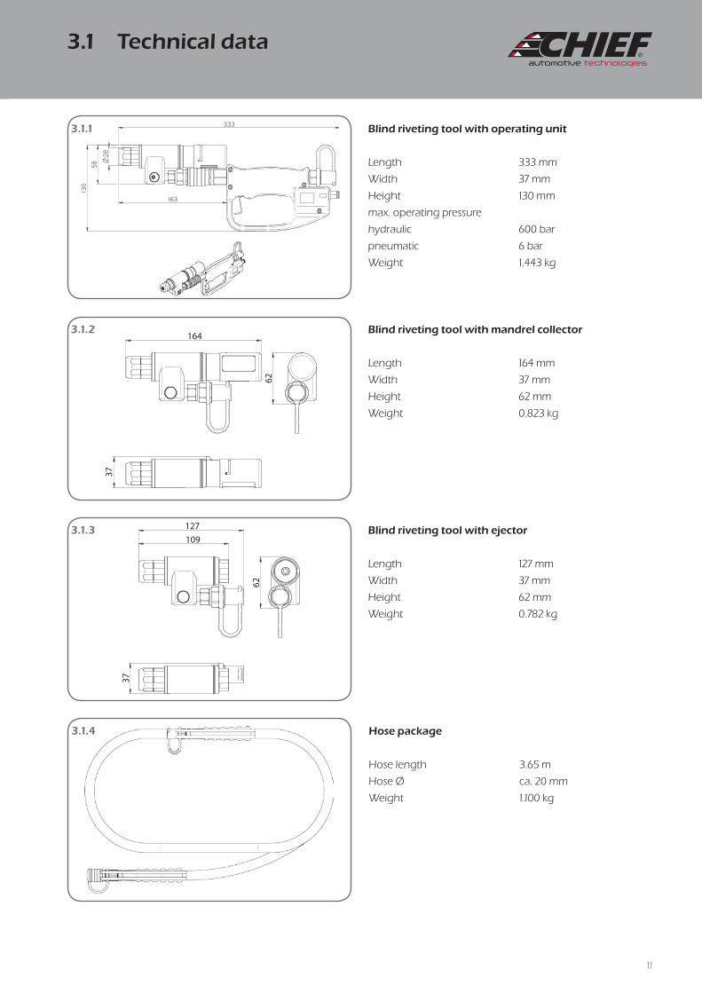
333 mm
37 mm
130 mm
600 bar
6 bar
1.443 kg
Length
Width
Height
max. operating pressure
hydraulic
pneumatic
Weight
Blind riveting tool with operating unit
164 mm
37 mm
62 mm
0.823 kg
Length
Width
Height
Weight
Blind riveting tool with mandrel collector
127 mm
37 mm
62 mm
0.782 kg
Length
Width
Height
Weight
Blind riveting tool with ejector
3.65 m
ca. 20 mm
1.100 kg
Hose length
Hose Ø
Weight
Hose package
3.1 Technical data

12
4.1.1
4.1.44.1.3
4.1.2
4.1.5
4.1.6
4.1.1/4.1.2
The operating unit and both hose package connections are
provided with protective caps. Remove the protective caps
from the corresponding couplings.
4.1.3/4.1.4
Connect up the operating unit and the hose by pulling back
the quick-release coupling and holding it as it is pushed on.
When the quick-release coupling is released the connection is
locked.
4.1.5/4.1.6
When connecting the pneumatic control hoses, make sure
that the black hose is attached to the coupling indicated.
The pneumatic hoses must be inserted right up to the stop.
4.1 Preparing the operating unit

13
4.2.1 4.2.2
4.2.3 4.2.4
4.2.5
4.2.6
Before using the equipment, check the
condition of the blind riveting tool with
add-on component and hoses. Risk of severe
bodily injury if the pump or the blind riveting
tool is damaged.
Check the hoses and couplings for damage.
In the event of any noticeable damage, the
hydraulic components must be replaced.
Damaged hoses or couplings could cause
severe injury!
Incorrectly attached hoses could come loose
and cause severe bodily injury.
4.2.5
When connecting the pneumatic control hoses, make sure
that the black hose is attached to the marked coupling.
black
blue
4.2 Preparing the pressure generator and
connecting up the operating unit
14
4.2.84.2.7
4.3.1
4.3.3
4.3.2
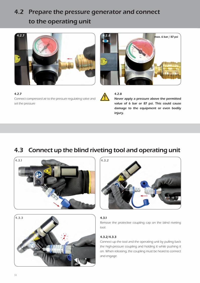
4.3.1
Remove the protective coupling cap on the blind riveting
tool.
4.3.2/4.3.3
Connect up the tool and the operating unit by pulling back
the high-pressure coupling and holding it while pushing it
on. When releasing, the coupling must be heard to connect
and engage.
4.2.8
Never apply a pressure above the permitted
value of 6 bar or 87 psi. This could cause
damage to the equipment or even bodily
injury.
4.2.7
Connect compressed air to the pressure regulating valve and
set the pressure
max. 6 bar / 87 psi
4.3 Connect up the blind riveting tool and operating unit
4.2 Prepare the pressure generator and connect
to the operating unit
15
7
3
4.4.1
4.4.2
4.4.3
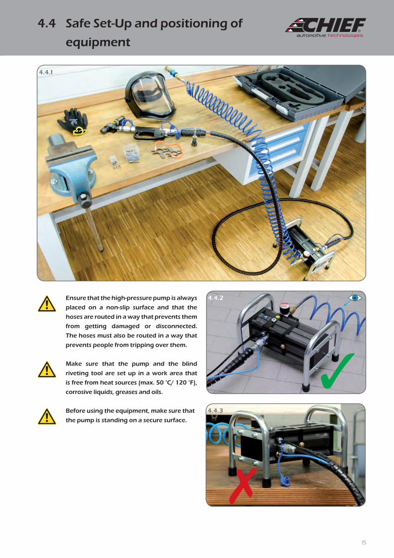
Ensure that the high-pressure pump is always
placed on a non-slip surface and that the
hoses are routed in a way that prevents them
from getting damaged or disconnected.
The hoses must also be routed in a way that
prevents people from tripping over them.
Make sure that the pump and the blind
riveting tool are set up in a work area that
is free from heat sources (max. 50 °C/ 120 °F),
corrosive liquids, greases and oils.
Before using the equipment, make sure that
the pump is standing on a secure surface.
4.4 Safe Set-Up and positioning of
equipment

16
5.1.3 5.1.4
5.1.5
5.1.1 5.1.2
5.1.6 5.1.7
5.1.1/5.1.2
Insert the blind rivet, centred in the tool's rivet guide. The rivet
head is held in place by the magnets.
5.1.3/5.1.4
Position the blind riveting tool and insert into the hole
provided as far as the contact surface.
5.1.5
Trigger riveting by pulling the lever.
5.1.6
The mandrel is pulled back into the tool during riveting. This
causes the rivet material to be spread out around the rivet
head on the opposite side.
5.1.7
The projecting part of the mandrel breaks at the front side at
the intended breaking point.
5.1 Fitting blind rivets

17
5.2.3 5.2.4
5.2.1 5.2.2
5.2.5
5.2.6
5.2.1
Press the mandrel collector towards the riveting tool, as
shown in the laser engraving.
5.2.2 – 5.2.4
The mandrel collector is turned to open the recovery aperture
to allow the mandrels to be removed.
5.2.5
To close, press the mandrel collector towards the riveting
tool, as shown in the laser engraving.
5.2.6
The mandrel collector is turned to close the recovery aperture.
Warning
Empty the mandrel collector after a maximum
of 10 riveting operations. If there are more
than 10 mandrels in the container, this can
result in damage being caused to the riveting
tool.
5.2 Emptying the mandrel collector

18
5.3.3 5.3.4
5.3.1 5.3.2
5.3.5
5.3.6
5.3.1/5.3.2
Turn the mandrel collector anti-clockwise.
5.3.3/5.3.4
Insert the ejector and tighten clockwise until the contact
surface is reached.
5.3.5/5.3.6
Tighten by hand using the large opening of the assembly
spanner.
When opening, keep the blind riveting tool
angled slightly forward. Otherwise the
conical grips may fall out.
When not in use, keep the ejector in the
protective cover provided for the purpose.
5.3 Fitting the ejector

19
5.4.1 5.4.2
5.4.3 5.4.4
5.4.5
5.4.6 5.4.7
5.4.1
Turn the mandrel collector anti-clockwise.
5.4.2
Remove the conical grip segments by turning the blind
riveting tool.
5.4.3
Locate the conical grip on the tip of the assembly aid.
5.4.4 – 5.4.7
Insert the assembly aid into the aperture on the blind riveting
tool and pull out towards the front.
Then refit the mandrel collector or the ejector.5.3
5.4 Replacing conical grip segments

20
5.5.1
5.5.3
5.5.2
5.4
5.5.1
Disconnect the blind riveting tool from the operating unit
and the compressed air supply.
5.5.2
Remove the three conical grips from the
casing.
5.5.3
Never use compressed air to clean the tool casing. This will
result in dirt being blown into the seals.
Use a soft, lint-free cloth to clean the tool.
Count the conical grips to ensure that none
has been left in the system. If a cone is left
behind the piston and the seal, damage will
be caused to both tool and cone.
Clean and check the gripper teeth on the
conical grips. Replace cones if blunt.
Worn gripper teeth can cause severe damage
to the tool.
5.5 Maintenance and cleaning

21
5.6.3
5.6.2
5.6.1
5.6.4
5.6.1
Always disconnect the compressed air supply
from the pump after blind riveting is complete or
during a work interruption.
5.6.2/5.6.3
Then disconnect the control hoses and seal all
ports.
Make sure that the disconnected hoses never
make contact with the dirty floor or the ground.
Foreign bodies or contamination in the
control lines could cause the equipment to
malfunction.
5.6.4
Only store the tool in the transport case
designed for this purpose. Make sure that the
hoses do not become kinked!
Never transport the tool by the hoses!
5.6 Completing an operation and
riveting tool storage
5.6.4

22
Problem Cause Remedy Page
Blind riveting tool not working
Compressed air supply not connected up Connect compressed air see Operating Instructions PNP 90
Control lines incorrectly connected Connect control lines correctly and ensure they are properly seated 12/13
Control lines not connected up Connect control lines correctly and ensure they are properly seated 12/13
Insufficient air pressure Check air supply at pressure intensifier 14
Hydraulic hose package not coupled up Connect up hydraulic hose package in accordance with Operating Instructions 12/13
Pump faulty Have repaired by manufacturer/service partner see Operating Instructions PNP 90
Blind riveting tool will not shut off
Control lines incorrectly connected Connect control lines correctly and ensure they are properly seated 12/13
Control lines not connected up Connect control lines correctly and ensure they are properly seated 12/13
Control valve faulty (operating unit) Have repaired by manufacturer/service partner 9
Pump faulty Have repaired by manufacturer/service partner see Operating Instructions PNP 90
Air leak Control valve faulty (operating unit) Have repaired by manufacturer/service partner 9
Blind rivet not being gripped, conical
grips slipping on mandrel
Conical grips dirty Carefully clean conical grips 19
Gripper teeth on conical grips worn Replace worn conical grips with new 19
Incorrect conical grips Check and replace conical grips 19
Blind riveting process not completed
Rivet mandrel not separated from
blind rivet head
Insufficient quantity of oil (pressure intensifier) Check oil level and top up if necessary see Operating Instructions PNP 90
Gripper teeth on conical grips worn Replace worn conical grips with new 19
Pump faulty Have repaired by manufacturer/service partner see Operating Instructions PNP 90
Insufficient air pressure Check air supply at pressure intensifier 14
Oil leak
Hydraulic hose package faulty Replace hydraulic hose package 12/13
High-pressure coupling faulty Have repaired by manufacturer/service partner 9
Blind riveting tool losing oil Have repaired by manufacturer/service partner 9
Screwing spring package/ejector
into housing requires application of
excessive force
Piston not in starting position - quantity of oil present in housingAllow residual oil pressure to disperse by connecting up the hydraulic hose and
the high-pressure push-fit nipple (wait 10-20 seconds)12/13
Faulty thread Check thread and replace ejector, if necessary 18
Blind rivet cannot be inserted
Conical grip segments in piston adapter (3-part) sitting in different positionsUnscrew rivet guide and gently push conical grip segments back 2-5 mm with a
blunt implement until they are evenly positioned19
Mandrel collector overfilled - broken off mandrels can no longer be carried backEmpty mandrel collector and mandrels left behind in housing
by pushing back with a blunt implement19
Incorrect conical grips Check and replace conical grips 19
6.1 Troubleshooting

23
Problem Cause Remedy Page
Blind riveting tool not working
Compressed air supply not connected up Connect compressed air see Operating Instructions PNP 90
Control lines incorrectly connected Connect control lines correctly and ensure they are properly seated 12/13
Control lines not connected up Connect control lines correctly and ensure they are properly seated 12/13
Insufficient air pressure Check air supply at pressure intensifier 14
Hydraulic hose package not coupled up Connect up hydraulic hose package in accordance with Operating Instructions 12/13
Pump faulty Have repaired by manufacturer/service partner see Operating Instructions PNP 90
Blind riveting tool will not shut off
Control lines incorrectly connected Connect control lines correctly and ensure they are properly seated 12/13
Control lines not connected up Connect control lines correctly and ensure they are properly seated 12/13
Control valve faulty (operating unit) Have repaired by manufacturer/service partner 9
Pump faulty Have repaired by manufacturer/service partner see Operating Instructions PNP 90
Air leak Control valve faulty (operating unit) Have repaired by manufacturer/service partner 9
Blind rivet not being gripped, conical
grips slipping on mandrel
Conical grips dirty Carefully clean conical grips 19
Gripper teeth on conical grips worn Replace worn conical grips with new 19
Incorrect conical grips Check and replace conical grips 19
Blind riveting process not completed
Rivet mandrel not separated from
blind rivet head
Insufficient quantity of oil (pressure intensifier) Check oil level and top up if necessary see Operating Instructions PNP 90
Gripper teeth on conical grips worn Replace worn conical grips with new 19
Pump faulty Have repaired by manufacturer/service partner see Operating Instructions PNP 90
Insufficient air pressure Check air supply at pressure intensifier 14
Oil leak
Hydraulic hose package faulty Replace hydraulic hose package 12/13
High-pressure coupling faulty Have repaired by manufacturer/service partner 9
Blind riveting tool losing oil Have repaired by manufacturer/service partner 9
Screwing spring package/ejector
into housing requires application of
excessive force
Piston not in starting position - quantity of oil present in housingAllow residual oil pressure to disperse by connecting up the hydraulic hose and
the high-pressure push-fit nipple (wait 10-20 seconds)12/13
Faulty thread Check thread and replace ejector, if necessary 18
Blind rivet cannot be inserted
Conical grip segments in piston adapter (3-part) sitting in different positionsUnscrew rivet guide and gently push conical grip segments back 2-5 mm with a
blunt implement until they are evenly positioned19
Mandrel collector overfilled - broken off mandrels can no longer be carried backEmpty mandrel collector and mandrels left behind in housing
by pushing back with a blunt implement19
Incorrect conical grips Check and replace conical grips 19
24
Zusammenfassung.pdf 1 02.10.13 10:09
1
3
2
4
5 6 7
Liefermöglichkeit VSG.pdf 1 10.06.15 14:55
1
3
2 3
6
9
4
5
7
8
10
11
www.chiefautomotive.com

25
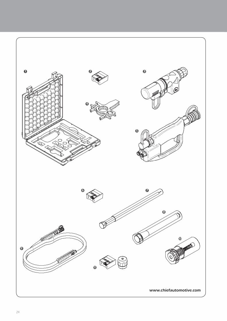
Item
no.Art. no. Name
4 CHR2202-4 Assembly spanner
5 CHR2222-5 Operating unit
6 CHR2202-2 1-part conical grip set for Ø 4.2 mm blind rivets*
7 CHR2202-7 Assembly aid in packaging
8 CHR2202-8 Extension
9 CHR2406 Hose package
10 CHR2202-9 Ejector in packaging
11 CHR2202-10 1-part conical grip set for Ø 2.6 mm blind rivets*
Item
no.Art. no. Name
1 CHR2202-1 Toolbox
2 CHR2202-2 1-part conical grip set for Ø 4.2 mm blind rivets
3 CHR2202-3 Blind riveting tool
4 CHR2202-4 Assembly spanner
5 CHR2202-5 Operating unit
6.3 Components
6.2 Spare parts

26
Appliances and machinery and components of appliances and machinery must be disposed of
in accordance with the laws, regulations and other stipulations of that country in which they
are located.
We recommend that disposal be undertaken by licensed professional operators.
6.5 Liability
6.4 Disposal
Chief Automotive Technologies, Inc. does not assume responsibility for any death, injury or prop-erty damage resulting from the operator’s negligence or misuse of this product or its attachments.
Chief makes no written, express or implied warranty whatsoever of merchantability or fitness for a particular purpose or otherwise regarding the equipment or any part of the product other than the limited one-year warranty stated in chapter 2.6.

27

Chief Automotive Technologies
Service
996 Industrial Drive
Madison, IN 47250
Phone: 800-445-9262
Fax: 866-275-0173
PSD
-BED
-000
0027
7 V
ers.
15.0
5