pneumatic ball valve zvs - bardiani.com
TRANSCRIPT
Instruction, Use and Maintenance Manual
PNEUMATIC BALL VALVE
Bardiani Valvole S.p.A.via G. di Vittorio, 50/52 - 43045 Fornovo di Taro (PR) - Italytel. +39 0525 - Fax 0525 [email protected] - www.bardiani.com
EN-IST-ZVS-0621
ZVS
(Translation of the Original Instructions in the italian Language)
EN-IST-ZVS-0621
MANUAL REVISION DATE
2

EN-IST-ZVS-0621
INDEX1 Safety,Warning and Mandatory Signs 5
1.1 Operator training 82 Safety 9
2.1 General safety warnings 92.2 Safety Devices: 9
3 Technical data 104 Checking / Unpacking / Lifting 115 Installation 136 Operation 157 Troubleshooting 168 Cleaning 179 Disposal 1810 Maintenance 19
10.1 General maintenance 1910.2 Scheduled maintenance 2010.3 Tools useful for Disassembly/Reassembly 2110.4 Pneumatic Ball Valve ZVS 2210.5 Disassembly of the ZVS 2310.6 Assembly of the ZVS 24
11 Annexes 2812 2D diagram ZVS DN10--65 2913 2D diagram ZVS DN65--100 3014 Warranty 3115 Recommendations 32
3
EN-IST-ZVS-0621
INTRODUCTION
This “Instruction, Use and Maintenance Manual” has been prepared to provide guidance and recommendations to assist qualified skilled technicians in the understanding, running and maintenance orf the Products supplied.
It forms an integral part of the Products supplied and must be read prior to any installation, operation and/or maintenance of all types of valves provided.
This manual must be saved for future reference and be kept readily available at the unit.
With regards to the use of valves compliant with EU Directive 2014/34/UE (ATEX), consultation of a specific manual is mandatory.
The essential characteristics of all types of valves described herein being consistent, the Manufacturer reserves the right to alter and or complement and or update at any time and with no obligation to notify so in writing, the data and or information relevant to the use of the valves described in this "Instruction, Use and Maintenance Manual".
A constantly updated version of this "Instruction, Use and Maintenance Manual" is available at the Manufacturer's website www.bardianivalvole.it.
Under no circumstance shall the Manufacturer be held liable for consequences resulting from failure and or improper use of the instructions contained in this Manual and relating to the installation, operating, maintenance and storage of the products.
All rights reserved.
Full or part reproduction, transfer and or recording of any part of this "Instruction, Use and Maintenance Manual" by all means, whether it be electronic, on hard copy, mechanical or any other means or recording or reuse is strictly prohibited without the prior written consent of the Manufacturer and for any use other than that of the Buyer.
4
EN-IST-ZVS-0621
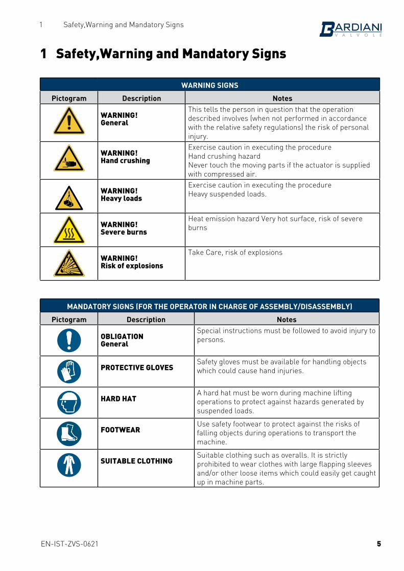
1 Safety,Warning and Mandatory Signs
1 Safety,Warning and Mandatory Signs
WARNING SIGNS
Pictogram Description Notes
WARNING! General
This tells the person in question that the operation described involves (when not performed in accordance with the relative safety regulations) the risk of personal injury.
WARNING! Hand crushing
Exercise caution in executing the procedureHand crushing hazardNever touch the moving parts if the actuator is supplied with compressed air.
WARNING! Heavy loads
Exercise caution in executing the procedureHeavy suspended loads.
WARNING! Severe burns
Heat emission hazard Very hot surface, risk of severe burns
WARNING! Risk of explosions
Take Care, risk of explosions
MANDATORY SIGNS (FOR THE OPERATOR IN CHARGE OF ASSEMBLY/DISASSEMBLY)
Pictogram Description Notes
OBLIGATION General
Special instructions must be followed to avoid injury to persons.
PROTECTIVE GLOVESSafety gloves must be available for handling objects which could cause hand injuries.
HARD HATA hard hat must be worn during machine lifting operations to protect against hazards generated by suspended loads.
FOOTWEARUse safety footwear to protect against the risks of falling objects during operations to transport the machine.
SUITABLE CLOTHINGSuitable clothing such as overalls. It is strictly prohibited to wear clothes with large flapping sleeves and/or other loose items which could easily get caught up in machine parts.
5

EN-IST-ZVS-0621
1 Safety,Warning and Mandatory Signs
MANDATORY SIGNS (FOR THE OPERATOR IN CHARGE OF MECHANICAL MAINTENANCE)
Pictogram Description Notes
OBLIGATION General
Special instructions must be followed to avoid injury to persons.
PROTECTIVE GLOVESProtective gloves must be available for handling objects which could cause hand injuries or when there is the possibility of coming into contact with harmful substances..
HARD HATHard hats must be available when lifting heavy parts.
FOOTWEARUse safety footwear to protect against injuries caused by falling objects during maintenance operations (particularly when dismantling parts).
SUITABLE CLOTHINGSuitable clothing such as overalls. It is strictly prohibited to wear clothes with large flapping sleeves and/or other loose items which could easily get caught up in machine parts.
SAFETY GLASSESProtective glasses must be available when there is the possibility of contact which harmful substances which could cause eye injuries.
OPERATING SIGNS
Pictogram Description Notes
PERSONALPERSONNEL
Dismantling/Assembling and maintenance operations must be carried out by expert technicians only.
NOTEFollow the indicated note with care
ENVIRONMENTAL NOTE
Follow the regulations in force in the country of used governing waste disposal.
CLAMPUse of a clamp
CLAMP WITH SOFT JAWS
Use of a clamp with jaws made from soft material
6
EN-IST-ZVS-0621
1 Safety,Warning and Mandatory Signs
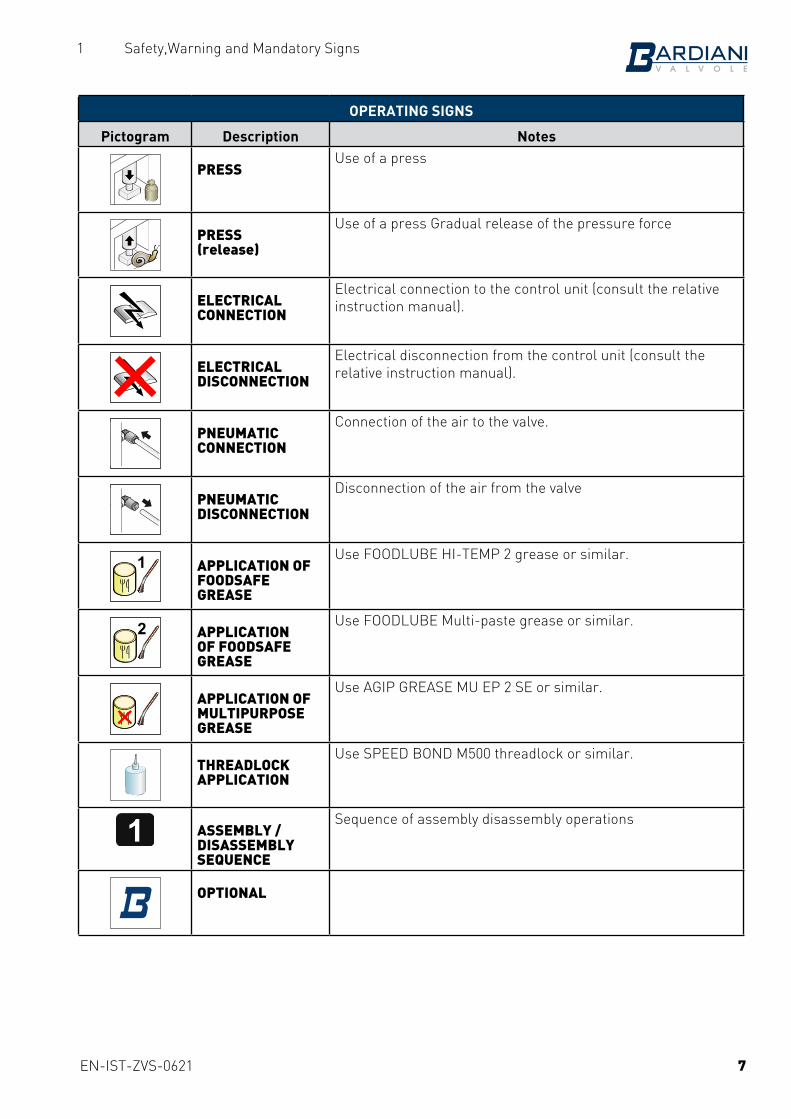
OPERATING SIGNS
Pictogram Description Notes
PRESSUse of a press
PRESS(release)
Use of a press Gradual release of the pressure force
ELECTRICAL CONNECTION
Electrical connection to the control unit (consult the relative instruction manual).
ELECTRICAL DISCONNECTION
Electrical disconnection from the control unit (consult the relative instruction manual).
PNEUMATIC CONNECTION
Connection of the air to the valve.
PNEUMATIC DISCONNECTION
Disconnection of the air from the valve
1 APPLICATION OF FOODSAFE GREASE
Use FOODLUBE HI-TEMP 2 grease or similar.
2 APPLICATION OF FOODSAFE GREASE
Use FOODLUBE Multi-paste grease or similar.
APPLICATION OF MULTIPURPOSE GREASE
Use AGIP GREASE MU EP 2 SE or similar.
THREADLOCK APPLICATION
Use SPEED BOND M500 threadlock or similar.
1 ASSEMBLY / DISASSEMBLY SEQUENCE
Sequence of assembly disassembly operations
OPTIONAL
7
EN-IST-ZVS-0621
1 Safety,Warning and Mandatory Signs
1.1 Operator training
All persons who have to work on the valve must be qualified to carry out the relative maintenance tasks. They must be informed as to the possible hazards involved and must observe all the safety instructions set out in this manual. Allow expert personnel only to work on the electrical components.
8

EN-IST-ZVS-0621
2 Safety
2 Safety2.1 General safety warnings
Intended useBardiani valves have been exclusively for moving fluids.
Prohibited useThe valve must not be used:• for any operations different to those described under the heading “Intended Use”,• for handling fluids different to the type specified by the manufacturer;• for moving fluids at different pressures to those envisaged by the manufacturer and indicated in the
valve's technical data.
Limitations on valve useIt is forbidden to:• use the valve in a construction configuration different to the one envisaged by the manufacturer.• use the valve where there is a risk of explosion and/or fire, unless envisaged by the manufacturer (if
the valves are certified in accordance with Directive 2014/34/EU, please refer to the ATEX Manual)-;• integrate other systems and/or equipment which were not considered by the manufacturer during the
executive design phase,• use the valve for purposes other than those specifically envisaged by the manufacturer.
WARNING!The machine may not he used inside premises where there is a potentially explosive atmosphere or risk of fire unless otherwise stated by the manufacturer (in the case of valves certified in accordance with Directive 2014/34/EU please refer to the ATEX Manual).
BARDIANI VALVOLE S.p.A. declines all liability for installation, use or maintenance which fails to comply with the indications provided in this manual!
2.2 Safety Devices:(see the control unit manual)
9
EN-IST-ZVS-0621
3 Technical data
3 Technical data
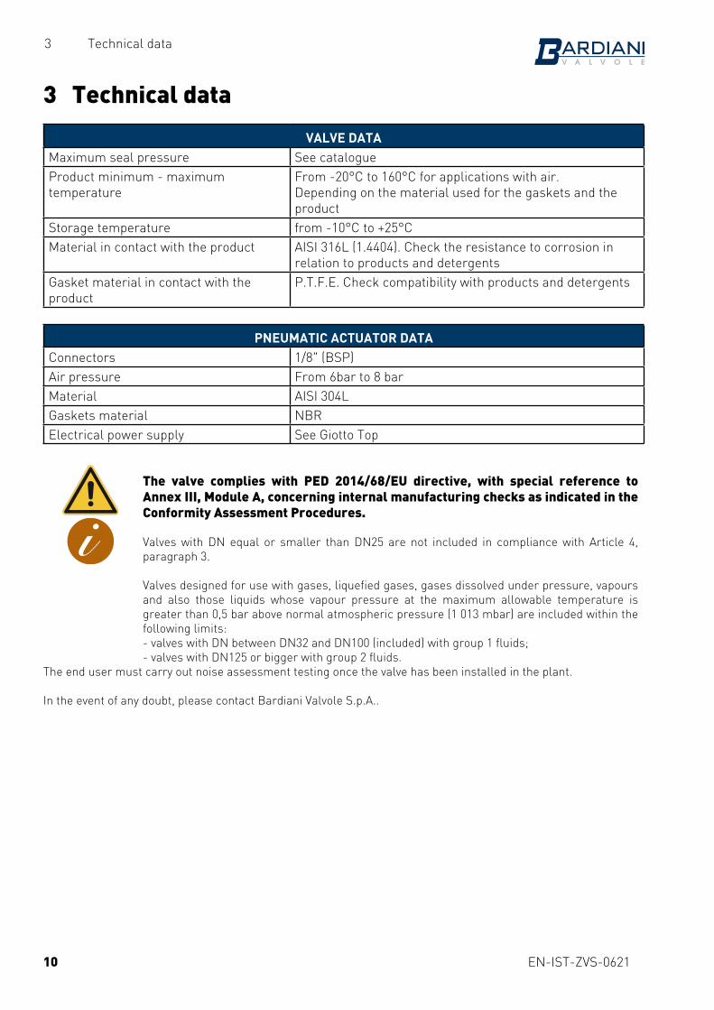
VALVE DATAMaximum seal pressure See catalogueProduct minimum - maximum temperature
From -20°C to 160°C for applications with air.Depending on the material used for the gaskets and the product
Storage temperature from -10°C to +25°CMaterial in contact with the product AISI 316L (1.4404). Check the resistance to corrosion in
relation to products and detergentsGasket material in contact with the product
P.T.F.E. Check compatibility with products and detergents
PNEUMATIC ACTUATOR DATAConnectors 1/8" (BSP)Air pressure From 6bar to 8 barMaterial AISI 304LGaskets material NBRElectrical power supply See Giotto Top
The valve complies with PED 2014/68/EU directive, with special reference to Annex III, Module A, concerning internal manufacturing checks as indicated in the Conformity Assessment Procedures. Valves with DN equal or smaller than DN25 are not included in compliance with Article 4, paragraph 3. Valves designed for use with gases, liquefied gases, gases dissolved under pressure, vapours and also those liquids whose vapour pressure at the maximum allowable temperature is greater than 0,5 bar above normal atmospheric pressure (1 013 mbar) are included within the following limits:- valves with DN between DN32 and DN100 (included) with group 1 fluids;- valves with DN125 or bigger with group 2 fluids.
The end user must carry out noise assessment testing once the valve has been installed in the plant.
In the event of any doubt, please contact Bardiani Valvole S.p.A..
10

EN-IST-ZVS-0621
4 Checking / Unpacking / Lifting
4 Checking / Unpacking / Lifting
1. CHECK: - Check the valve show no signs of damage caused during transport
and that it corresponds with the order; - Check the inside of the valve.
2. UNPACKINGThe valve packaging is made up of cardboard, wood and plastic.The valve is mainly made up of metal materials. The gaskets are usually made from elastomers. Disposal must be in compliance with local legislation.
11

EN-IST-ZVS-0621
4 Checking / Unpacking / Lifting
Weight up to 25 kg
CAUTION!The figures above are used purely to represent the methods and procedures for hoisting the valves.Bardiani Valvole S.p.A. declines all liability for any damage to things and/or injuries to persons caused by improper and/or incorrect hoisting of the valve.
ZVS
SizeDN
Lifting method
15--50 A65--150 B
Weight between 25 kg and 50 kg
3. VALVE LIFTING:Take care as to the type of valve you are handling. Based on the size there are different lifting procedures.
CAUTION!Before lifting the valve, make sure there are no disassembled or separate valve parts which could fall off causing injury to persons and damage to the valve.
12
BA
EN-IST-ZVS-0621
5 Installation
5 Installation
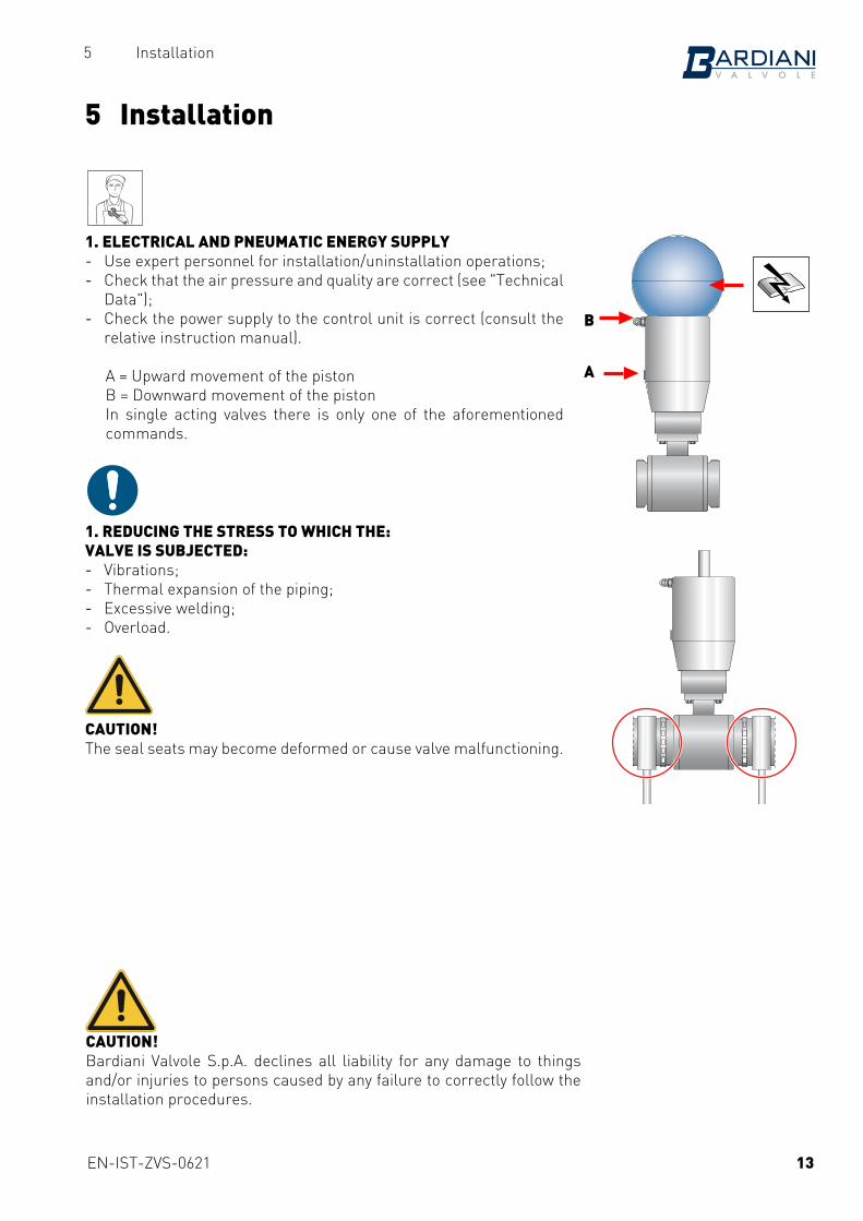
1. ELECTRICAL AND PNEUMATIC ENERGY SUPPLY - Use expert personnel for installation/uninstallation operations; - Check that the air pressure and quality are correct (see "Technical
Data"); - Check the power supply to the control unit is correct (consult the
relative instruction manual).
A = Upward movement of the pistonB = Downward movement of the pistonIn single acting valves there is only one of the aforementioned commands.
1. REDUCING THE STRESS TO WHICH THE:VALVE IS SUBJECTED: - Vibrations; - Thermal expansion of the piping; - Excessive welding; - Overload.
CAUTION!The seal seats may become deformed or cause valve malfunctioning.
CAUTION!Bardiani Valvole S.p.A. declines all liability for any damage to things and/or injuries to persons caused by any failure to correctly follow the installation procedures.
13
B
A

EN-IST-ZVS-0621
5 Installation
2. VALVE CONNECTIONS/CONNECTORS:If the valve is fitted with connectors, you may proceed with installation. Correctly insert the gaskets and tighten the connectors.
3. WELDING THE VALVE BODY ONTO PIPING:Remove the body from the rest of the valve before proceeding with welding operations. Please refer to the following pages in this manual.
WARNING!Hand crushing hazard.
4. MINIMUM MAINTENANCE CLEARANCES:Make sure there is enough room to disassemble the valve.
ZVS
Valve dimension
(DN)A (mm)
10--65 21065--100 220
CAUTION!Bardiani Valvole S.p.A. declines all liability for any damage to things and/or injuries to persons caused by any failure to correctly follow the installation procedures.
14
A
EN-IST-ZVS-0621
6 Operation
6 Operation
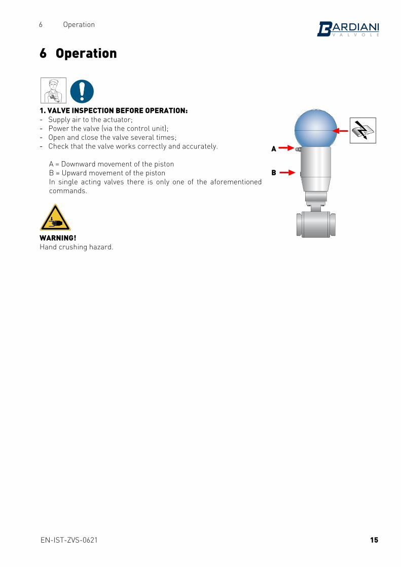
1. VALVE INSPECTION BEFORE OPERATION: - Supply air to the actuator; - Power the valve (via the control unit); - Open and close the valve several times; - Check that the valve works correctly and accurately.
A = Downward movement of the pistonB = Upward movement of the pistonIn single acting valves there is only one of the aforementioned commands.
WARNING!Hand crushing hazard.
15
A
B
EN-IST-ZVS-0621
7 Troubleshooting
7 Troubleshooting
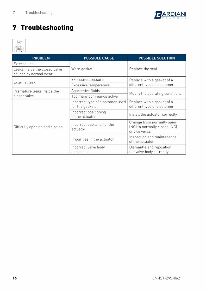
PROBLEM POSSIBLE CAUSE POSSIBLE SOLUTIONExternal leak
Worn gasket Replace the sealLeaks inside the closed valve caused by normal wear
External leakExcessive pressure Replace with a gasket of a
different type of elastomerExcessive temperature
Premature leaks inside the closed valve
Aggressive fluidsModify the operating conditions
Too many commands active
Difficulty opening and closing
Incorrect type of elastomer used for the gaskets
Replace with a gasket of a different type of elastomer
Incorrect positioningof the actuator Install the actuator correctly
Incorrect operation of the actuator
Change from normally open(NO) to normally closed (NC)or vice versa.
Impurities in the actuator Inspection and maintenanceof the actuator
Incorrect valve body positioning
Dismantle and repositionthe valve body correctly
16
EN-IST-ZVS-0621
8 Cleaning
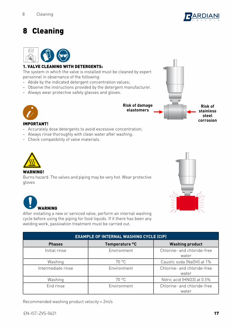
1. VALVE CLEANING WITH DETERGENTS:The system in which the valve is installed must be cleaned by expert personnel in observance of the following: - Abide by the indicated detergent concentration values; - Observe the instructions provided by the detergent manufacturer. - Always wear protective safety glasses and gloves.
IMPORTANT! - Accurately dose detergents to avoid excessive concentration; - Always rinse thoroughly with clean water after washing. - Check compatibility of valve materials.
WARNING!Burns hazard. The valves and piping may be very hot. Wear protective gloves
WARNINGAfter installing a new or serviced valve, perform an internal washing cycle before using the piping for food liquids. If it there has been any welding work, passivation treatment must be carried out.
EXAMPLE OF INTERNAL WASHING CYCLE (CIP)
Phases Temperature °C Washing productInitial rinse Environment Chlorine- and chloride-free
waterWashing 70 °C Caustic soda (NaOH) at 1%
Intermediate rinse Environment Chlorine- and chloride-free water
Washing 70 °C Nitric acid (HNO3) at 0.5%End rinse Environment Chlorine- and chloride-free
water
Recommended washing product velocity = 2m/s
8 Cleaning
Risk of stainless
steel corrosion
Risk of damageelastomers
17
EN-IST-ZVS-0621
9 Disposal
9 Disposal
At the end of its service life, the device must be recycled in accordance with the legislation in force in the country of valve use. Any hazardous residues must be taken into consideration and adequately handled.The valve is made of AISI 316L and AISI 304 stainless steel, elastomers (gaskets), plastic (control unit) and electrical components (terminal boards, solenoid valves, sensors).
Adhere to the following steps before disconnecting the valve and refer to the heading "General Maintenance". - make sure the line on which the valve is installed in is not in use - empty the line on which the valve is installed and clean if necessary - disconnect the air supply if it is not required during dismantling - disconnect the valve from the power supply - remove the valve from the system - move the valve in observance of the rules set out in the heading "Lifting" - to dismantle the valve, refer to the heading "Disassembly"
18
EN-IST-ZVS-0621
10 Maintenance
10 Maintenance
10.1 General maintenance
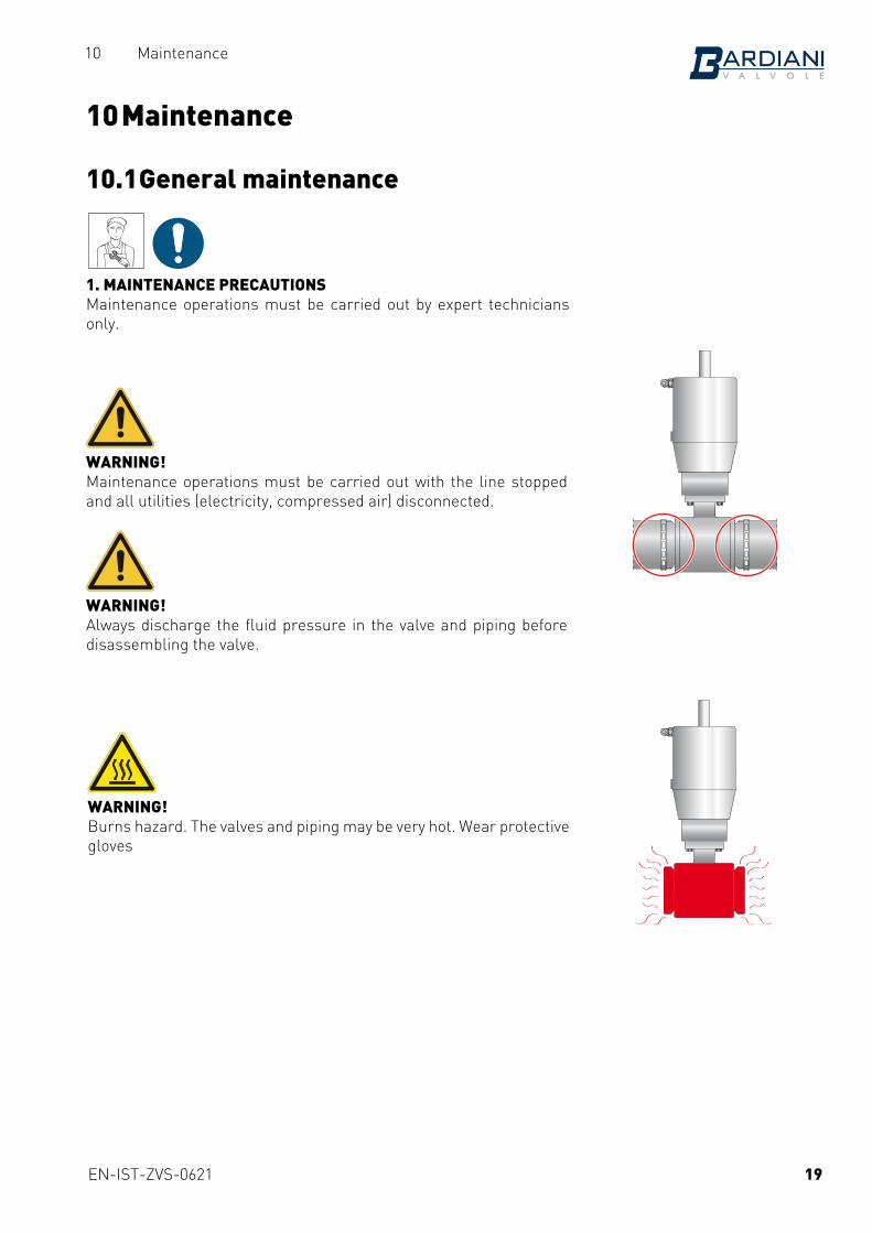
1. MAINTENANCE PRECAUTIONSMaintenance operations must be carried out by expert technicians only.
WARNING!Maintenance operations must be carried out with the line stopped and all utilities (electricity, compressed air) disconnected.
WARNING!Always discharge the fluid pressure in the valve and piping before disassembling the valve.
WARNING!Burns hazard. The valves and piping may be very hot. Wear protective gloves
19
EN-IST-ZVS-0621
10 Maintenance
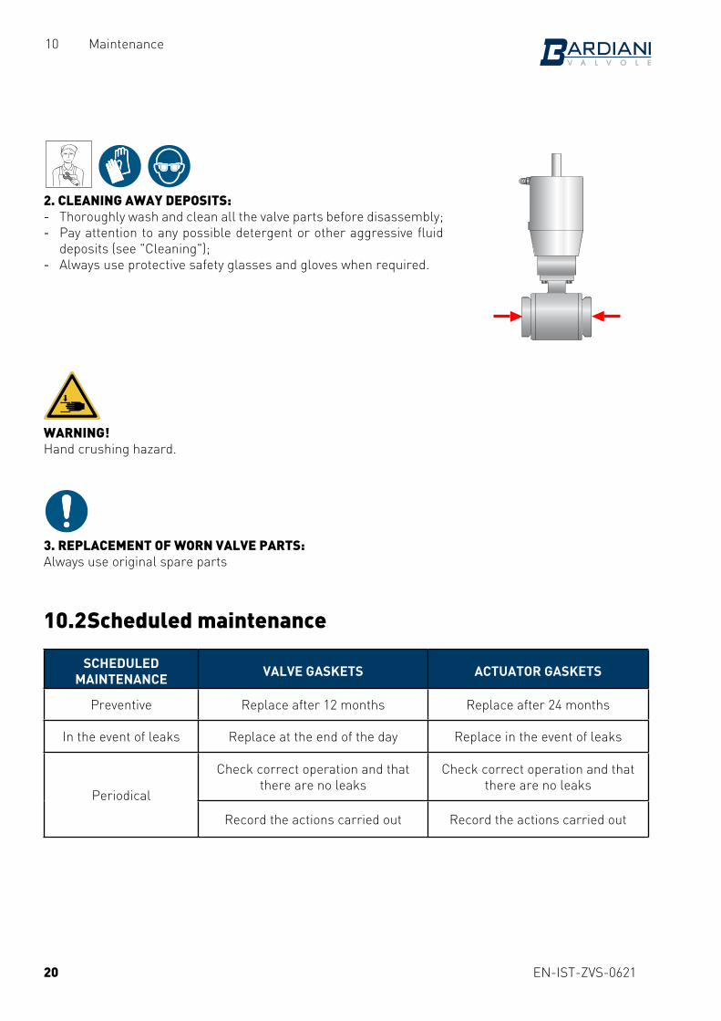
2. CLEANING AWAY DEPOSITS: - Thoroughly wash and clean all the valve parts before disassembly; - Pay attention to any possible detergent or other aggressive fluid
deposits (see "Cleaning"); - Always use protective safety glasses and gloves when required.
WARNING!Hand crushing hazard.
3. REPLACEMENT OF WORN VALVE PARTS:Always use original spare parts
10.2 Scheduled maintenance
SCHEDULED MAINTENANCE VALVE GASKETS ACTUATOR GASKETS
Preventive Replace after 12 months Replace after 24 months
In the event of leaks Replace at the end of the day Replace in the event of leaks
Periodical
Check correct operation and that there are no leaks
Check correct operation and that there are no leaks
Record the actions carried out Record the actions carried out
20
EN-IST-ZVS-0621
10 Maintenance
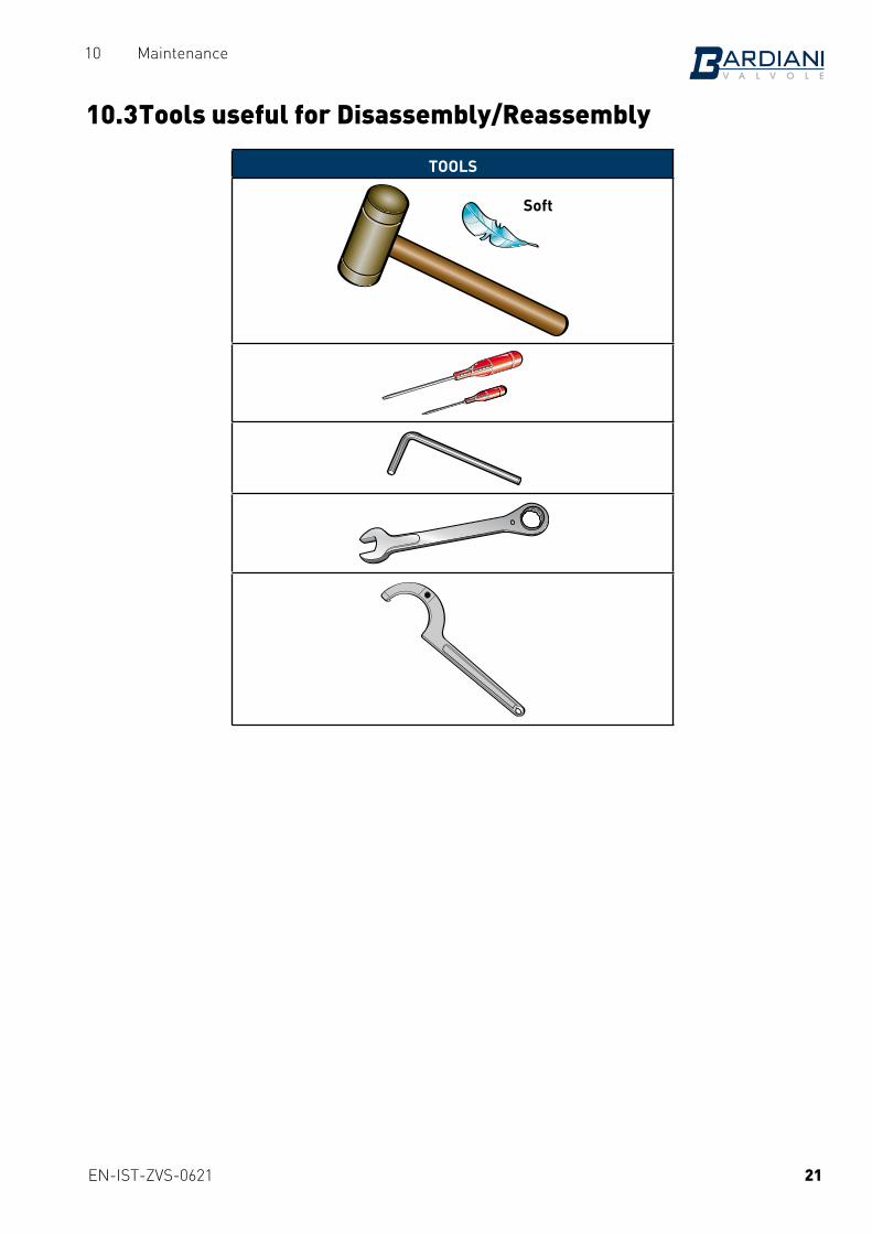
10.3 Tools useful for Disassembly/Reassembly
TOOLS
Soft
21
EN-IST-ZVS-0621
10 Maintenance
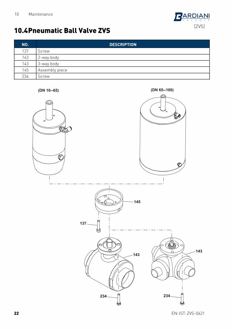
10.4 Pneumatic Ball Valve ZVS
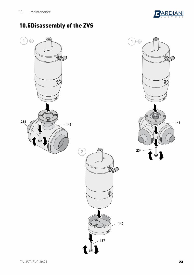
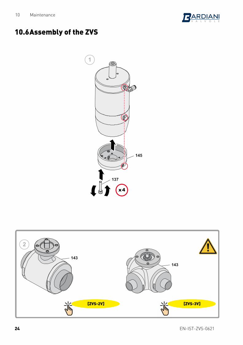
NO. DESCRIPTION137 Screw143 2-way body143 3-way body145 Assembly piece234 Screw
22
(DN 65--100)(DN 10--65)
145
137
143143
234 234
[ZVS]
EN-IST-ZVS-0621
10 Maintenance
10.5 Disassembly of the ZVS
23
145
137
2
143234 143
234
11 ba
EN-IST-ZVS-0621
10 Maintenance
10.6 Assembly of the ZVS
24
143143
1
145
137
x 4
2
[ZVS-2V] [ZVS-3V]
EN-IST-ZVS-0621
10 Maintenance
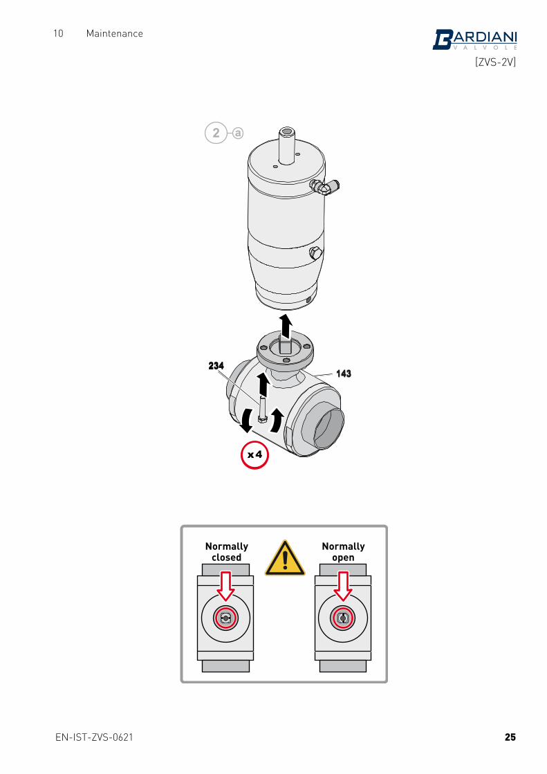
Normallyclosed
Normallyopen
25
143234
x 4
143234
x 4
2 a
[ZVS-2V]

EN-IST-ZVS-0621
10 Maintenance
Type "L"
26
143
234
x 4
2 b
A
A-B
B
D90°
[ZVS-3V]
EN-IST-ZVS-0621
10 Maintenance
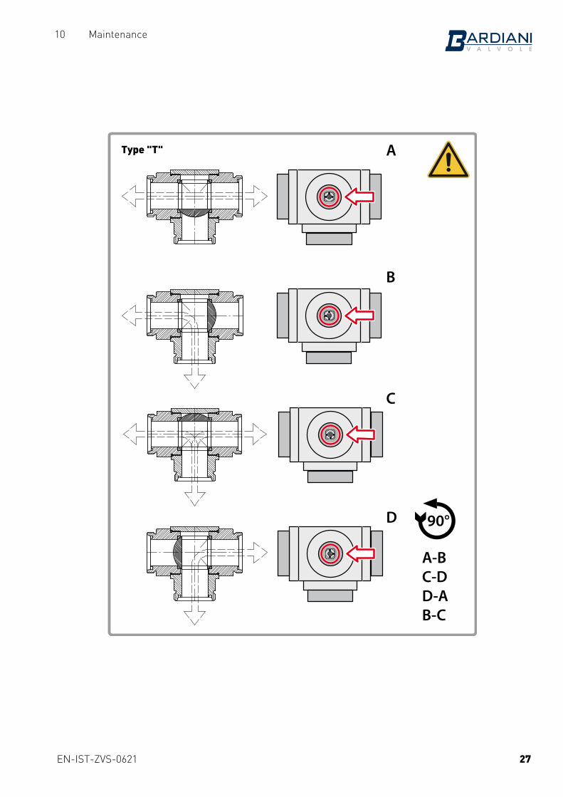
Type "T"
27
A
A-BC-DD-AB-C
B
C
D D90°

EN-IST-ZVS-0621
11 Annexes
11 Annexes
28
BARDIANI VALVOLE S.p.A.. Via G. di Vittorio 50/52
43045 Fornovo di Taro (Pr)
GB - EC Declaration of conformity - without eletric components - A5-P-PRG-GB
A5-P-PRG-GB Ed. 1. Rev. 0
EC DECLARATION OF CONFORMITY OF THE MACHINERY
(EC) 2006/42, Annex. II, p. 1 A
BARDIANI VALVOLE S.p.A. Via G. di Vittorio 50/52 – 43045 Fornovo di Taro (Pr) – Italia
Declares
under its own responsibility that the machine:
Type: PPNNEEUUMMAATTIICC VVAALLVVEESS
Model: ################
Serial number: ################
Function: Fluid handling
Year of construction: 2018
Reference ################
complies with all relevant provisions of the following EC directives:
(EC) 2006/42 MACHINERY
and the following harmonized standards, rules and / or technical specifications applied:
EN ISO 12100:2010
REGULATION (EC) 1935/2004 and subsequent amendments and additions with regard to steel and elastomers in contact with the product
Fornovo di Taro
20/09/2018 ______________________________
Legal Representative
EN-IST-ZVS-0621
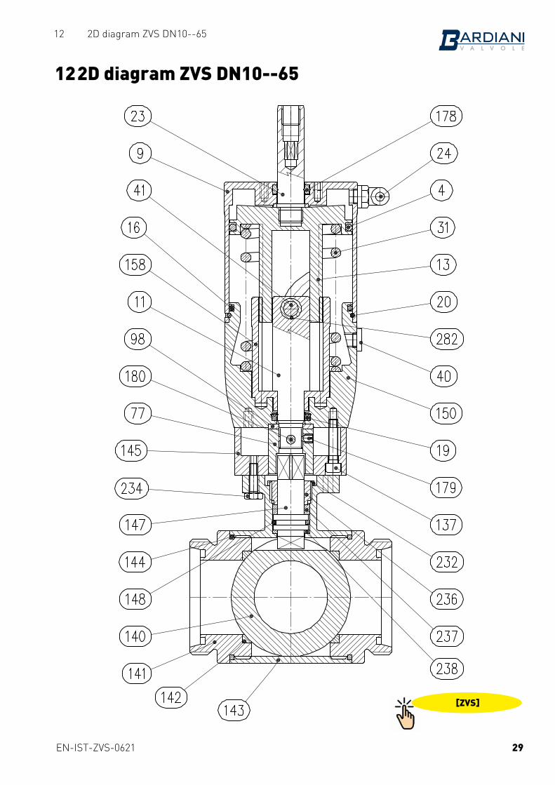
12 2D diagram ZVS DN10--65
12 2D diagram ZVS DN10--65
29
[ZVS]
EN-IST-ZVS-0621
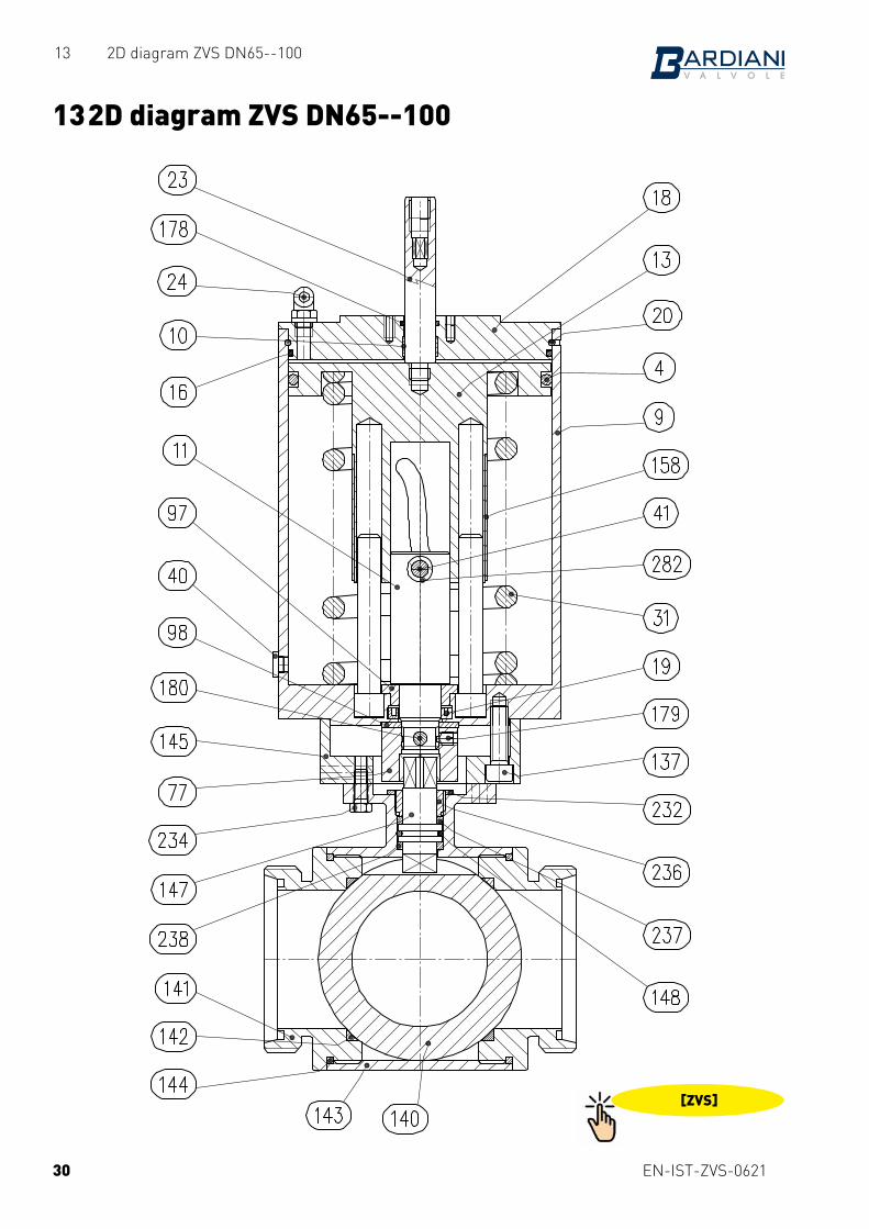
13 2D diagram ZVS DN65--100
13 2D diagram ZVS DN65--100
30
[ZVS]
EN-IST-ZVS-0621
14 Warranty
14 Warranty1. VALIDITYBardiani Valvole‘s Products are manufactured in compliance with the technical specifications laid out in their “Instruction, Use and Maintenance Manual” and are fully compliant with the directives specifically mentioned in these manuals.Bardiani Valvole S.p.A. guarantees its own Products against any design and/or construction and/or material defects and/or faults for a period of 12 (twelve) months from the date of delivery.Notification of any Product defects and/or faults must be sent in writing to Bardiani Valvole S.p.A. within 8 (eight) days from their detection, providing adequate documentation of the defect/fault encountered as evidence.Services provided in the warranty period shall not result in an extension of the warranty beyond the stipulated 12 (twelve)-month period, as this warranty validity period is to be considered mandatory.
2. CONTENTS OF THE WARRANTYNotwithstanding and without prejudice to the rights of the Buyer, which may be acknowledged by applicable law, this warranty it to be intended as limited, at the discretion of Bardiani Valvole S.p.A., to the repair and/or replacement of the Product and/or part of the Product and/or its components which is/are found to be defective due to design and/or manufacturing and/or material faults. - In the event of repair and/or replacement of the Product and/or any one of its parts and/or components,
any returned item/s shall become the property of Bardiani Valvole S.p.A. and the relative shipping costs shall charged to Bardiani Valvole S.p.A.
- Bardiani Valvole S.p.A., shall be under no obligation to compensate for any immaterial and/or indirect damages and shall in no way be held liable for consequential damages and/or losses, such as (by way of example only), damages due to loss of business, contracts, opportunities, time, production, profits, goodwill, image etc.
- No retailer or distributor or dealer or agent or representative or employee or person appointed by Bardiani Valvole S.p.A. is authorized to make any amendments and/or integrations and/or extensions to this warranty.
3. WARRANTY EXCLUSIONS - Elastomers and electrical components are expressly excluded from this warranty. - This warranty does not cover design faults emerging whenever a Product is manufactured by Bardiani
Valvole S.p.A. based on designs and/or technical specifications provided by the Buyer. - Moreover this warranty excludes the following: - faults and/or defects resulting from incorrect and/or unsuitable and/or inadequate transportation of
the Product; - faults and/or defects resulting from failure to comply with the indications laid out in the “Instruction,
Use and Maintenance Manual” with regards to installation of the Product or in any event caused by incorrect and/or unsuitable and/or improper installation;
- faults and/or defects resulting from failure to comply with indications laid out in the “Instruction, Use and Maintenance Manual” with regards to use and/or maintenance operations and/or storage of the Product or in any event caused by incorrect and/or unsuitable and/or improper use and/or maintenance operations and/or storage;
- faults and/or defects due to normal wear and tear of the Product and/or its parts and/or its components; - faults and/or defects in the Product and/or its parts and/or its components for work and/or repairs
being carried out by unskilled staff or staff that has not been authorised by Bardiani Valvole S.p.A.; - faults and/or defects in the Product and/or its parts and/or its components due to it/them being dropped
and/or banged and/or dented and/or misused and/or tampering and/or breakage and/or accidents or in any event due to negligence and/or carelessness and/or neglect by the Buyer and in general for any causes not attributable to design and/or manufacturing and/or material defects;
- faults and/or defects in the Product and/or its parts and/or its components caused by other events beyond the control of Bardiani Valvole S.p.A., such as force majeure or unforseeable circumstances.
31
EN-IST-ZVS-0621
15 Recommendations
15 Recommendations
1. Consultation of the "Instruction, Use and Maintenance Manual” is mandatory prior to the installation, use and maintenance of the products of all Products. All the information, indications, specifications, technical details provided herein are based on test data which the Manufacturer Bardiani Valvole S.p.A. holds to be reliable nevertheless the above is not deemed to be assumed as fully exhaustive inasmuch as not every possible use has been envisaged.
2. All the illustrations and drawings provided are to be intended as indicative and therefore not binding, the illustrations being for presentation purposes only.
3. It is the Buyer's duty to assess the suitability of the products for the use he intends to make of the same prior to placing the order as he/she will take the risks and accept liability in case of incorrect choice and use of the Products.
4. The Manufacturer strongly recommends the Buyer to contact their sales team and request any information that might be needed in relation to the specifications and uses of the Products.
5. The information provided in this manual refers to the standard products manufactured by Bardiani Valvole S.p.A. and therefore cannot be assumed to apply to customized products as well.
6. Bardiani Valvole S.p.A. reserves the right to amend and/or integrate and/or update the data and/or information and/or technical details relative to Products at any time and without prior notice. Please visit the website www.bardiani.com, where the latest updated of the "Instruction, Use and Maintenance Manual" can be found".
7. The content and validity of the warranty covering the Products of Bardiani Valvole S.p.A are dealt with in the relevant section in the “Instruction, Use and Maintenance Manual” which constitutes an integral part of the Products themselves.
8. Bardiani Valvole S.p.A., shall not in any way be held liable for immaterial, indirect and consequential damages, such as (by way of example only), damages or loss of business, contracts, opportunities, time, production, profits, goodwill, image etc..
32
EN-IST-ZVS-0621
15 Recommendations
NOTES
33
Bardiani Valvole S.p.A.via G. di Vittorio, 50/52 - 43045 Fornovo di Taro (PR) - Italy
tel. +39 0525 400044 - fax +39 0525 [email protected] - www.bardiani.com