pmu-based distributed state estimation with the ... · pdf filepanama-romeville 230 kv...
TRANSCRIPT
PSERC Seminar, June 17, 2008 PSERC1
A. P. Sakis MeliopoulosGeorgia Power Distinguished Professor
School of Electrical and Computer Engineering
Georgia Institute of Technology
PMU-Based Distributed State Estimation with the
SuperCalibratorPSERC Seminar
June 17, 2008
PSERC Seminar, June 17, 2008 PSERC2
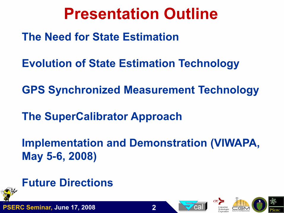
Presentation Outline
The Need for State Estimation
Evolution of State Estimation Technology
GPS Synchronized Measurement Technology
The SuperCalibrator Approach
Implementation and Demonstration (VIWAPA,
May 5-6, 2008)
Future Directions
PSERC Seminar, June 17, 2008 PSERC3
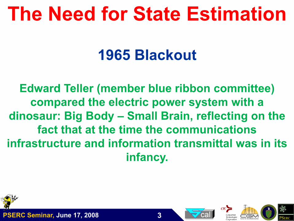
The Need for State Estimation
1965 Blackout
Edward Teller (member blue ribbon committee)
compared the electric power system with a
dinosaur: Big Body – Small Brain, reflecting on the
fact that at the time the communications
infrastructure and information transmittal was in its
infancy.
PSERC Seminar, June 17, 2008 PSERC4
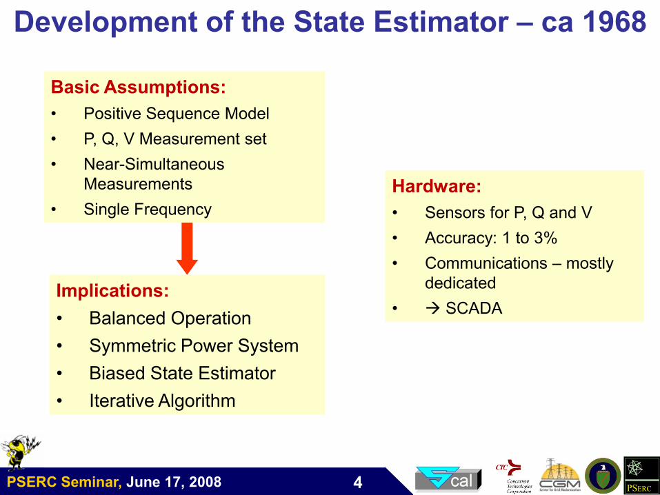
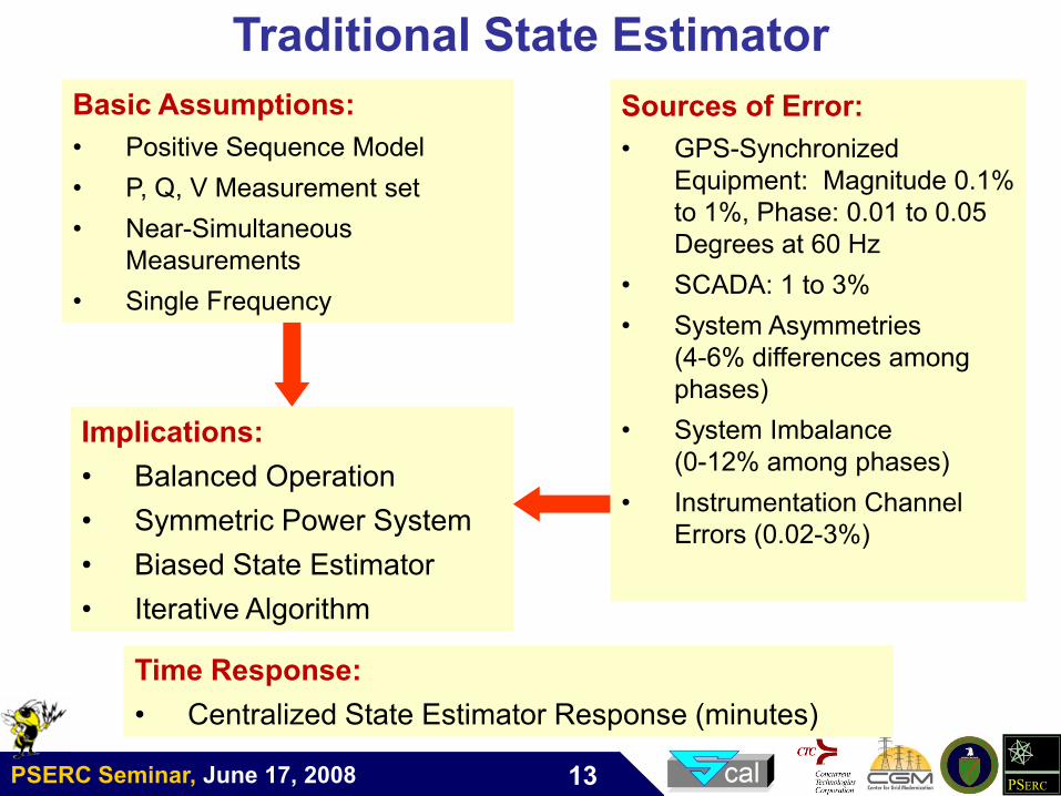
Basic Assumptions:
• Positive Sequence Model
• P, Q, V Measurement set
• Near-Simultaneous
Measurements
• Single Frequency
Basic Assumptions:
• Positive Sequence Model
• P, Q, V Measurement set
• Near-Simultaneous
Measurements
• Single Frequency
Implications:
• Balanced Operation
• Symmetric Power System
• Biased State Estimator
• Iterative Algorithm
Implications:
• Balanced Operation
• Symmetric Power System
• Biased State Estimator
• Iterative Algorithm
Hardware:
• Sensors for P, Q and V
• Accuracy: 1 to 3%
• Communications – mostly
dedicated
• SCADA
Hardware:
• Sensors for P, Q and V
• Accuracy: 1 to 3%
• Communications – mostly
dedicated
• SCADA
Development of the State Estimator – ca 1968
PSERC Seminar, June 17, 2008 PSERC5
Evolution of Supervisory
Control – State Estimation in
Power Systems
PSERC Seminar, June 17, 2008 PSERC6
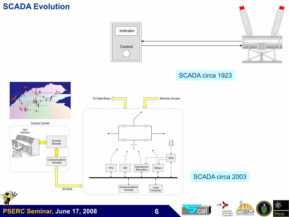
Indicator
Control
Control Center
CommunicationsTerminal
EncoderDecoder
UserInterface
RTU IED DisturbanceRecorders
Relays
GPS
LocalComputer
CommunicationsTerminal
To Data Base Remote Access
SCADA
SCADA circa 1923
SCADA circa 2003
SCADA Evolution
PSERC Seminar, June 17, 2008 PSERC7
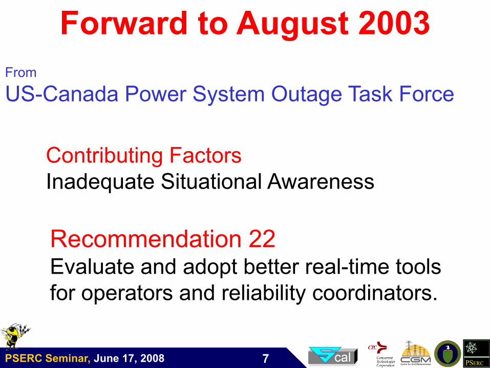
Forward to August 2003
Recommendation 22Evaluate and adopt better real-time tools
for operators and reliability coordinators.
From
US-Canada Power System Outage Task Force
Contributing Factors
Inadequate Situational Awareness
PSERC Seminar, June 17, 2008 PSERC8
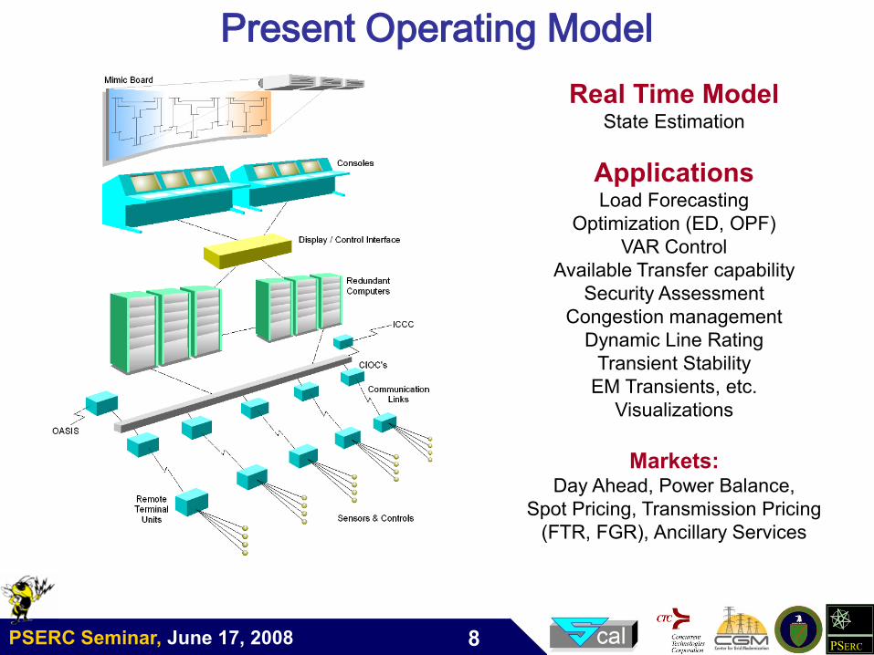
Real Time ModelState Estimation
ApplicationsLoad Forecasting
Optimization (ED, OPF)
VAR Control
Available Transfer capability
Security Assessment
Congestion management
Dynamic Line Rating
Transient Stability
EM Transients, etc.
Visualizations
Markets: Day Ahead, Power Balance,
Spot Pricing, Transmission Pricing
(FTR, FGR), Ancillary Services
Present Operating Model
PSERC Seminar, June 17, 2008 PSERC9
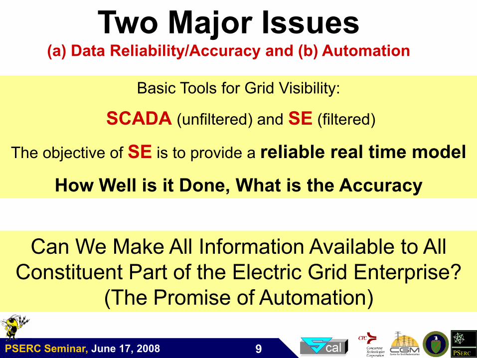
Basic Tools for Grid Visibility:
SCADA (unfiltered) and SE (filtered)
The objective of SE is to provide a reliable real time model
How Well is it Done, What is the Accuracy
Two Major Issues(a) Data Reliability/Accuracy and (b) Automation
Can We Make All Information Available to All
Constituent Part of the Electric Grid Enterprise?
(The Promise of Automation)
PSERC Seminar, June 17, 2008 PSERC10
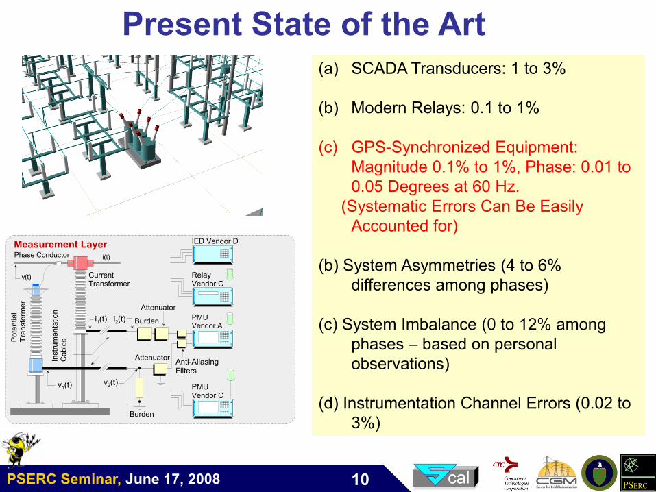
(a) SCADA Transducers: 1 to 3%
(b) Modern Relays: 0.1 to 1%
(c) GPS-Synchronized Equipment:
Magnitude 0.1% to 1%, Phase: 0.01 to
0.05 Degrees at 60 Hz.
(Systematic Errors Can Be Easily
Accounted for)
(b) System Asymmetries (4 to 6%
differences among phases)
(c) System Imbalance (0 to 12% among
phases – based on personal
observations)
(d) Instrumentation Channel Errors (0.02 to
3%)
Present State of the Art
Phase Conductor
Pote
ntial
Tra
nsfo
rmer
CurrentTransformer
PMUVendor A
Burden
Instr
um
enta
tion
Cable
s
v(t)
v1(t)v2(t)
Burdeni2(t)i1(t)
i(t)
Attenuator
AttenuatorAnti-AliasingFilters
RelayVendor C
PMUVendor C
Measurement Layer IED Vendor D
PSERC Seminar, June 17, 2008 PSERC11
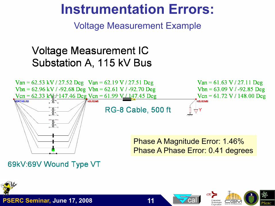
Instrumentation Errors:Voltage Measurement Example
Phase A Magnitude Error: 1.46%
Phase A Phase Error: 0.41 degrees
Phase A Magnitude Error: 1.46%
Phase A Phase Error: 0.41 degrees
PSERC Seminar, June 17, 2008 PSERC12
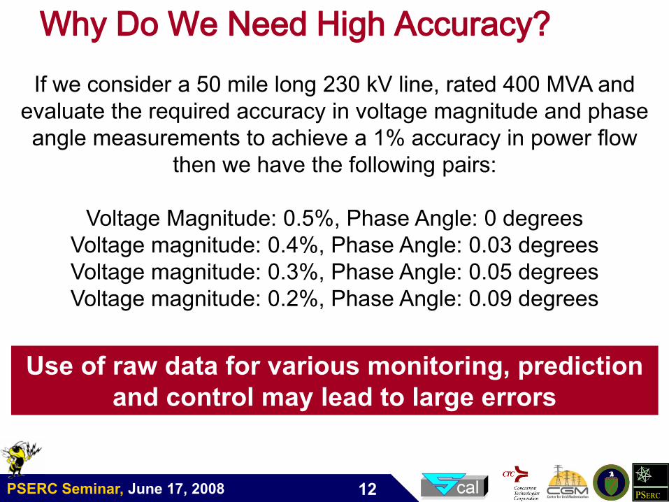
Why Do We Need High Accuracy?
Use of raw data for various monitoring, prediction
and control may lead to large errors
If we consider a 50 mile long 230 kV line, rated 400 MVA and
evaluate the required accuracy in voltage magnitude and phase
angle measurements to achieve a 1% accuracy in power flow
then we have the following pairs:
Voltage Magnitude: 0.5%, Phase Angle: 0 degrees
Voltage magnitude: 0.4%, Phase Angle: 0.03 degrees
Voltage magnitude: 0.3%, Phase Angle: 0.05 degrees
Voltage magnitude: 0.2%, Phase Angle: 0.09 degrees
PSERC Seminar, June 17, 2008 PSERC13
Basic Assumptions:
• Positive Sequence Model
• P, Q, V Measurement set
• Near-Simultaneous
Measurements
• Single Frequency
Basic Assumptions:
• Positive Sequence Model
• P, Q, V Measurement set
• Near-Simultaneous
Measurements
• Single Frequency
Implications:
• Balanced Operation
• Symmetric Power System
• Biased State Estimator
• Iterative Algorithm
Implications:
• Balanced Operation
• Symmetric Power System
• Biased State Estimator
• Iterative Algorithm
Sources of Error:
• GPS-Synchronized
Equipment: Magnitude 0.1%
to 1%, Phase: 0.01 to 0.05
Degrees at 60 Hz
• SCADA: 1 to 3%
• System Asymmetries
(4-6% differences among
phases)
• System Imbalance
(0-12% among phases)
• Instrumentation Channel
Errors (0.02-3%)
Sources of Error:
• GPS-Synchronized
Equipment: Magnitude 0.1%
to 1%, Phase: 0.01 to 0.05
Degrees at 60 Hz
• SCADA: 1 to 3%
• System Asymmetries
(4-6% differences among
phases)
• System Imbalance
(0-12% among phases)
• Instrumentation Channel
Errors (0.02-3%)
Traditional State Estimator
Time Response:
• Centralized State Estimator Response (minutes)
Time Response:
• Centralized State Estimator Response (minutes)
PSERC Seminar, June 17, 2008 PSERC14
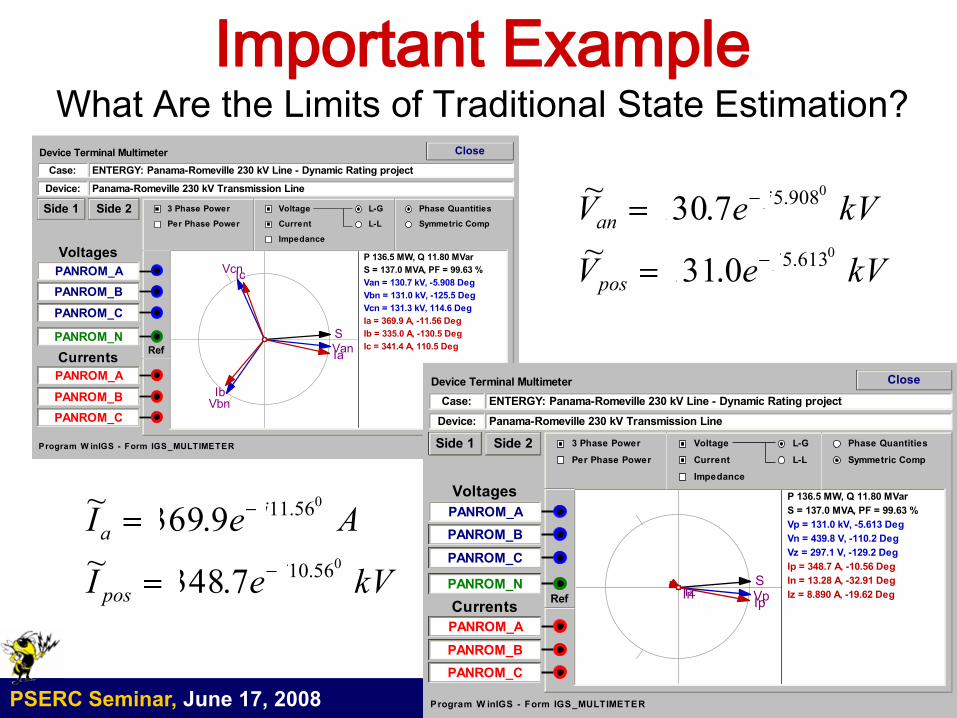
Important ExampleWhat Are the Limits of Traditional State Estimation?
Close
ENTERGY: Panama-Romeville 230 kV Line - Dynamic Rating project
P 136.5 MW, Q 11.80 MVar
S = 137.0 MVA, PF = 99.63 %
S
Van = 130.7 kV, -5.908 Deg
Vbn = 131.0 kV, -125.5 Deg
Vcn = 131.3 kV, 114.6 Deg
Van
Vbn
Vcn
Ia = 369.9 A, -11.56 Deg
Ib = 335.0 A, -130.5 Deg
Ic = 341.4 A, 110.5 DegIa
Ib
Ic
Panama-Romeville 230 kV Transmission Line
Case:
Device:
PANROM_A
PANROM_B
PANROM_C
PANROM_A
PANROM_B
PANROM_C
Voltages
Currents
3 Phase Power Voltage
CurrentPer Phase Power
Phase Quantities
Symmetric Comp
PANROM_NRef
Device Terminal Multimeter
L-G
L-L
Side 1 Side 2
Impedance
Program W inIGS - Form IGS_MULTIMETER
Close
ENTERGY: Panama-Romeville 230 kV Line - Dynamic Rating project
P 136.5 MW, Q 11.80 MVar
S = 137.0 MVA, PF = 99.63 %
S
Vp = 131.0 kV, -5.613 Deg
Vn = 439.8 V, -110.2 Deg
Vz = 297.1 V, -129.2 Deg
Vp
Ip = 348.7 A, -10.56 Deg
In = 13.28 A, -32.91 Deg
Iz = 8.890 A, -19.62 DegIp
InIz
Panama-Romeville 230 kV Transmission Line
Case:
Device:
PANROM_A
PANROM_B
PANROM_C
PANROM_A
PANROM_B
PANROM_C
Voltages
Currents
3 Phase Power Voltage
CurrentPer Phase Power
Phase Quantities
Symmetric Comp
PANROM_NRef
Device Terminal Multimeter
L-G
L-L
Side 1 Side 2
Impedance
Program W inIGS - Form IGS_MULTIMETER
kVeV
kVeV
j
pos
j
an
0
0
613.5
908.5
0.131~
7.130~
kVeI
AeI
j
pos
j
a
0
0
56.10
56.11
7.348~
9.369~
PSERC Seminar, June 17, 2008 PSERC15
GPS Synchronized Measurements
Enable Distributed State Estimation
PSERC Seminar, June 17, 2008 PSERC16
History of GPS-Synchronized
Measurements
Efforts to Develop Technologies with Accurate Time Synchronization
Started in the Early 80’s. Examples:
Missout & Girard, 1980
Bonanomi, 1981
Phadke, 1989-90
These efforts resulted in technologies with time synchronization accuracy
that was several tens of microseconds.
In 1992, Macrodyne (Jay Murphy) introduced the first PMU (Phasor
Measurement Unit) capable of taking measurements with synchronization
comparable to GPS clock accuracy (microsecond accuracy)
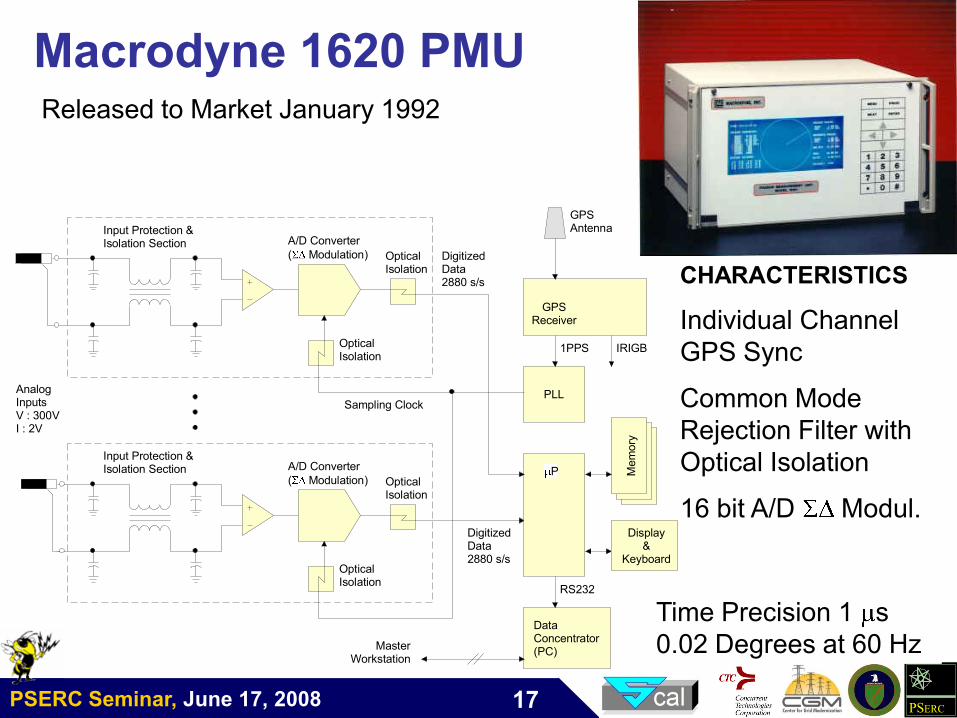
PSERC Seminar, June 17, 2008 PSERC17
Macrodyne 1620 PMU
A/D Converter
( Modulation)
Input Protection &Isolation Section
OpticalIsolation
P Mem
ory
PLL
Digitized Data2880 s/s
A/D Converter
( Modulation)
Input Protection &Isolation Section
OpticalIsolation
Sampling Clock
GPSReceiver
Digitized Data2880 s/s
1PPS IRIGB
GPSAntenna
DataConcentrator(PC)
Display&
Keyboard
RS232
MasterWorkstation
OpticalIsolation
OpticalIsolation
AnalogInputsV : 300VI : 2V
Released to Market January 1992
CHARACTERISTICS
Individual Channel
GPS Sync
Common Mode
Rejection Filter with
Optical Isolation
16 bit A/D Modul.
Time Precision 1 s
0.02 Degrees at 60 Hz
Time Precision 1 s
0.02 Degrees at 60 Hz
PSERC Seminar, June 17, 2008 PSERC18
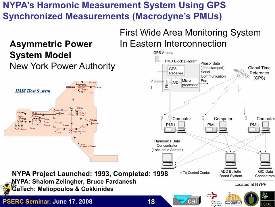
NYPA’s Harmonic Measurement System Using GPS
Synchronized Measurements (Macrodyne’s PMUs)
I
Global Time
Reference
(GPS)
GPS
Receiver
Micro
processorA/D
Phasor data
(time stamped)Serial
Communication
Port
Filt
er
To Control Center
Harmonics Data
Concentrator
(Located in Atlanta)
PMU Block Diagram
V
GPS Antena
ADD Bulletin
Board System
GIC Data
Concentrator
Located at NYPP
PMU
Computer
PMU
Computer
PMU
Computer
Asymmetric Power
System Model
New York Power Authority
NYPA Project Launched: 1993, Completed: 1998NYPA: Shalom Zelingher, Bruce Fardanesh
GaTech: Meliopoulos & Cokkinides
First Wide Area Monitoring System
In Eastern Interconnection
First Wide Area Monitoring System
In Eastern Interconnection
PSERC Seminar, June 17, 2008 PSERC19
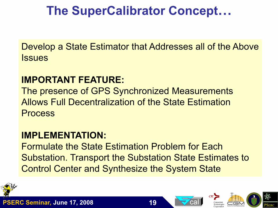
The SuperCalibrator Concept…
Develop a State Estimator that Addresses all of the Above
Issues
IMPORTANT FEATURE:
The presence of GPS Synchronized Measurements
Allows Full Decentralization of the State Estimation
Process
IMPLEMENTATION:
Formulate the State Estimation Problem for Each
Substation. Transport the Substation State Estimates to
Control Center and Synthesize the System State
PSERC Seminar, June 17, 2008 PSERC20
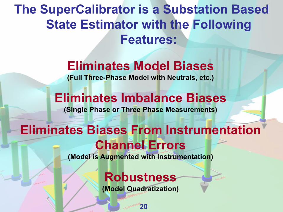
The SuperCalibrator is a Substation Based
State Estimator with the Following
Features:
Eliminates Model Biases(Full Three-Phase Model with Neutrals, etc.)
Eliminates Imbalance Biases(Single Phase or Three Phase Measurements)
Eliminates Biases From Instrumentation
Channel Errors(Model is Augmented with Instrumentation)
Robustness(Model Quadratization)
20
PSERC Seminar, June 17, 2008 PSERC21
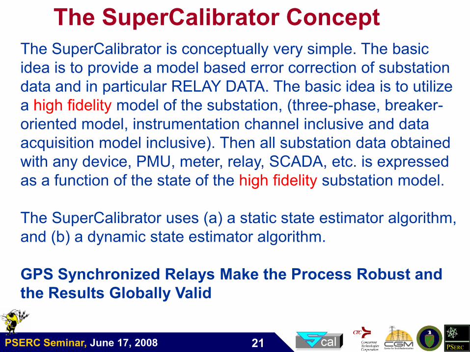
The SuperCalibrator is conceptually very simple. The basic
idea is to provide a model based error correction of substation
data and in particular RELAY DATA. The basic idea is to utilize
a high fidelity model of the substation, (three-phase, breaker-
oriented model, instrumentation channel inclusive and data
acquisition model inclusive). Then all substation data obtained
with any device, PMU, meter, relay, SCADA, etc. is expressed
as a function of the state of the high fidelity substation model.
The SuperCalibrator uses (a) a static state estimator algorithm,
and (b) a dynamic state estimator algorithm.
GPS Synchronized Relays Make the Process Robust and
the Results Globally Valid
The SuperCalibrator Concept
PSERC Seminar, June 17, 2008 PSERC22
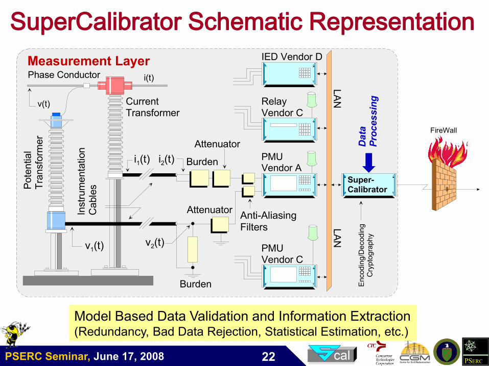
SuperCalibrator Schematic Representation
Phase Conductor
Pote
ntial
Tra
nsfo
rmer
CurrentTransformer
PMUVendor A
Burden
Instr
um
enta
tion
Cable
sv(t)
v1(t)v2(t)
Burdeni2(t)i1(t)
i(t)
Attenuator
AttenuatorAnti-AliasingFilters
RelayVendor C
PMUVendor C
Measurement Layer
Super-Calibrator
Data
Processing
IED Vendor D
LA
NLA
N
FireWall
Encod
ing/D
ecodin
gC
ryp
tog
raph
y
Model Based Data Validation and Information Extraction(Redundancy, Bad Data Rejection, Statistical Estimation, etc.)
PSERC Seminar, June 17, 2008 PSERC23
SuperCalibrator
Implementation on the
VIWAPA System

PSERC Seminar, June 17, 2008 PSERC24
Demonstration (Pilot) Project
Pilot project for demonstrating the application of the SuperCalibrator concept for
distributed state estimation on the US Virgin Islands power network.
St. Thomas Island
St. John
Island
US Virgin Islands consist of the main islands of St. Croix, St. John and St. Thomas, along with
many other surrounding minor islands.
The network is a stand-alone power system and is not connected to the US national power
grid.
The SuperCalibrator is implemented on the St. Thomas and St. John Islands power system –
the system has five substations and a generating plant.
Each substation has at least one SEL 421 relay or SEL 734 with GPS-synchronized
measurement capability.
PSERC Seminar, June 17, 2008 PSERC25
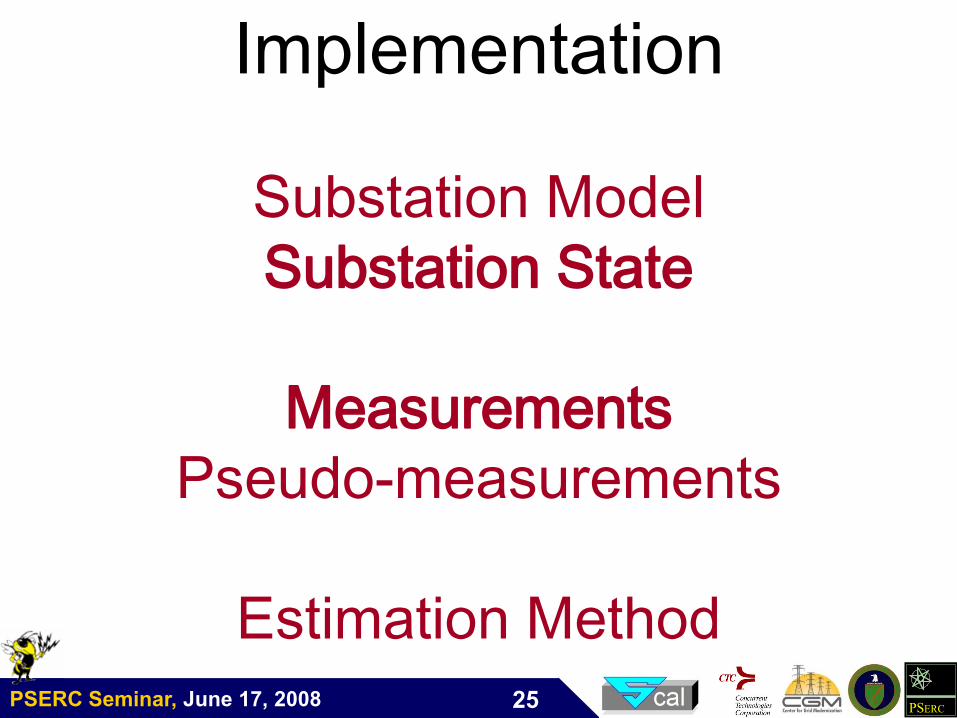
Implementation
Substation Model
Substation State
Measurements
Pseudo-measurements
Estimation Method
PSERC Seminar, June 17, 2008 PSERC26
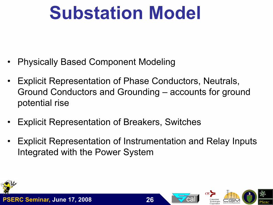
Substation Model
• Physically Based Component Modeling
• Explicit Representation of Phase Conductors, Neutrals,
Ground Conductors and Grounding – accounts for ground
potential rise
• Explicit Representation of Breakers, Switches
• Explicit Representation of Instrumentation and Relay Inputs
Integrated with the Power System
PSERC Seminar, June 17, 2008 PSERC27
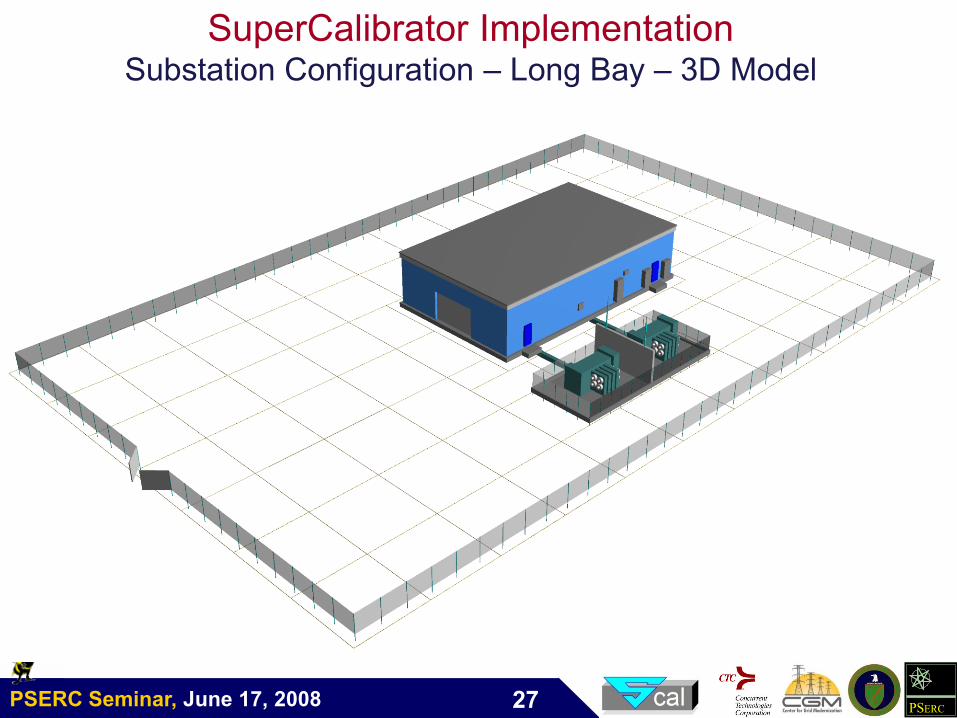
SuperCalibrator ImplementationSubstation Configuration – Long Bay – 3D Model
PSERC Seminar, June 17, 2008 PSERC28
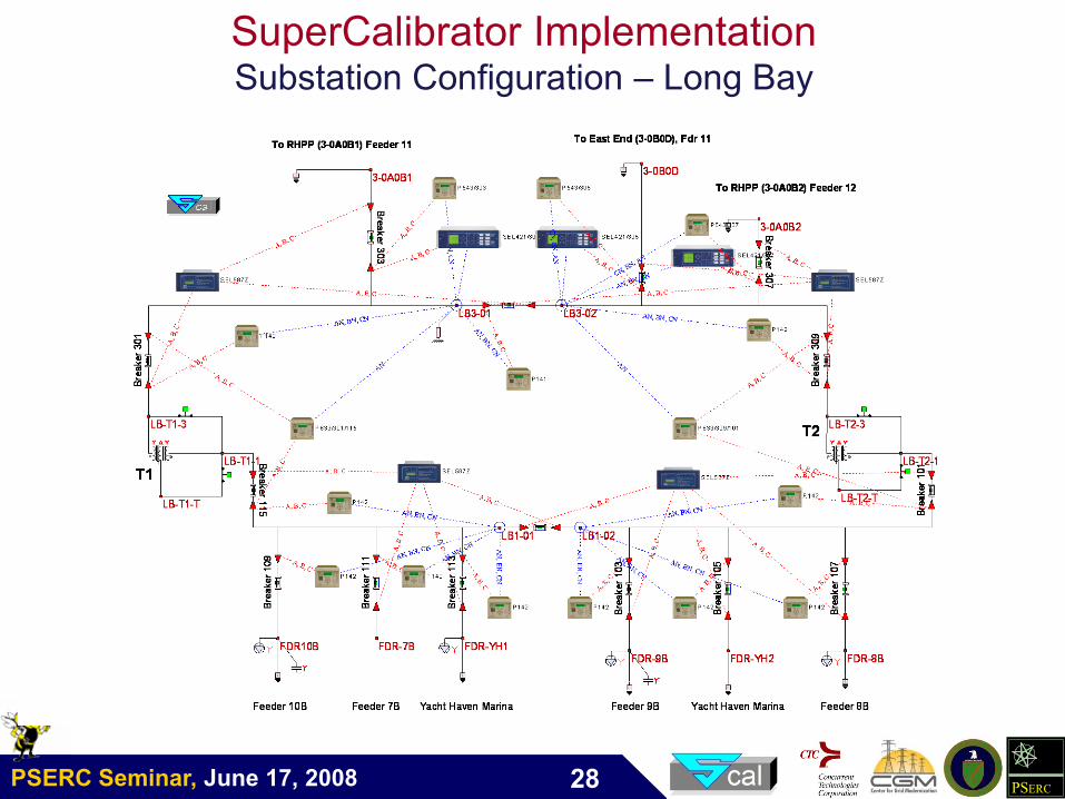
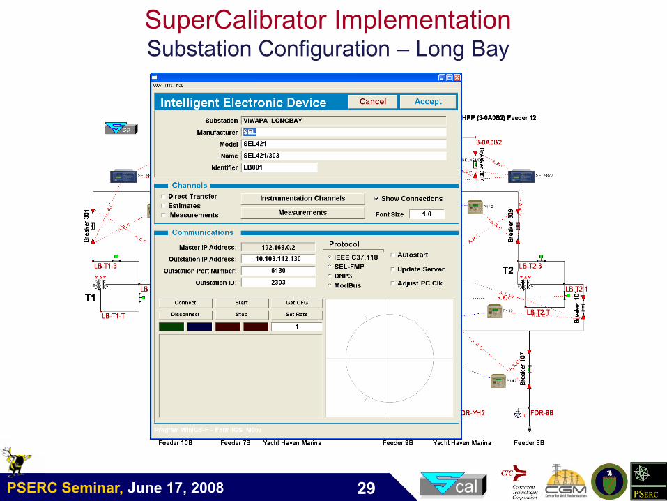
SuperCalibrator ImplementationSubstation Configuration – Long Bay
PSERC Seminar, June 17, 2008 PSERC29
SuperCalibrator ImplementationSubstation Configuration – Long Bay
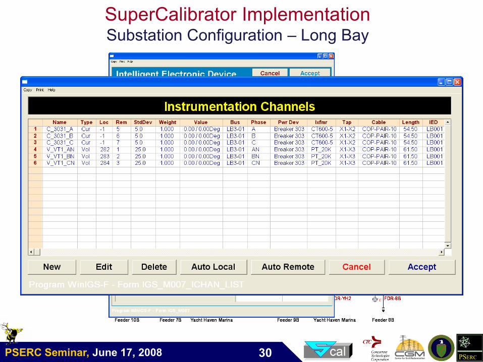
PSERC Seminar, June 17, 2008 PSERC30
SuperCalibrator ImplementationSubstation Configuration – Long Bay
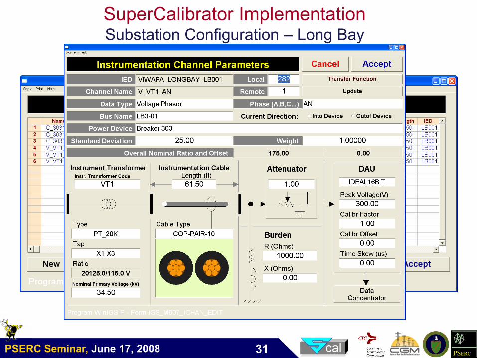
PSERC Seminar, June 17, 2008 PSERC31
SuperCalibrator ImplementationSubstation Configuration – Long Bay
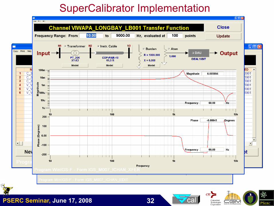
PSERC Seminar, June 17, 2008 PSERC32
SuperCalibrator ImplementationSubstation Configuration – Long Bay
PSERC Seminar, June 17, 2008 PSERC33
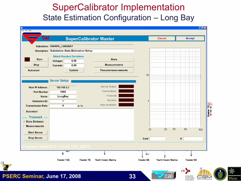
SuperCalibrator ImplementationState Estimation Configuration – Long Bay
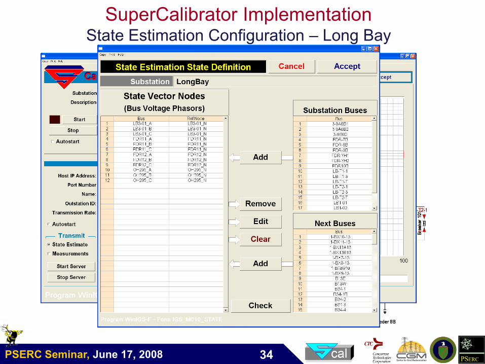
PSERC Seminar, June 17, 2008 PSERC34
SuperCalibrator ImplementationState Estimation Configuration – Long Bay
PSERC Seminar, June 17, 2008 PSERC35
State Definition Substation
V1e
~V2e
~
V3e
~V4e
~
V1s
~V2s
~
Definition of State for a Substation
sV1
~Vector of dimension 4: nscsbsas VVVV ,1,1,1,1
~,
~,
~,
~
sV2
~Vector of dimension 4: nscsbsas VVVV ,2,2,2,2
~,
~,
~,
~
eV1
~Vector of dimension 4: necebeae VVVV ,2,2,2,2
~,
~,
~,
~
…… …
eV4
~Vector of dimension 4: necebeae VVVV ,4,4,4,4
~,
~,
~,
~
SuperCalibrator
Static State Estimation
Substation State
PSERC Seminar, June 17, 2008 PSERC36
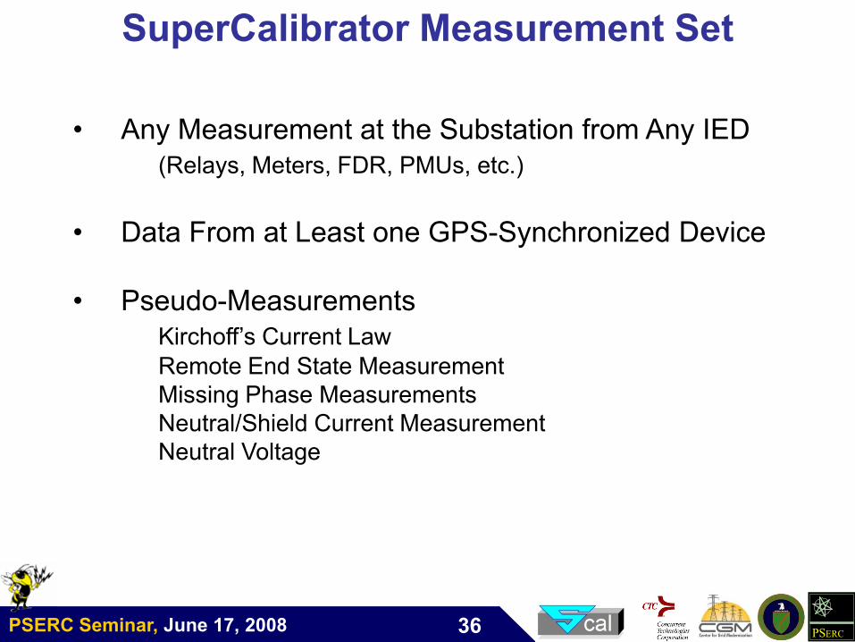
SuperCalibrator Measurement Set
• Any Measurement at the Substation from Any IED
(Relays, Meters, FDR, PMUs, etc.)
• Data From at Least one GPS-Synchronized Device
• Pseudo-Measurements
Kirchoff’s Current Law
Remote End State Measurement
Missing Phase Measurements
Neutral/Shield Current Measurement
Neutral Voltage
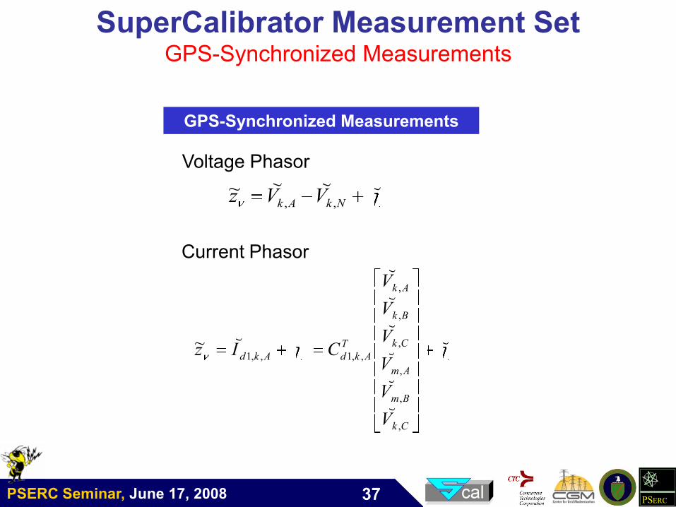
PSERC Seminar, June 17, 2008 PSERC37
SuperCalibrator Measurement SetGPS-Synchronized Measurements
~~~~,, NkAk VVz
~
~
~
~
~
~
~
~~
,
,
,
,
,
,
,,1,,1
Ck
Bm
Am
Ck
Bk
Ak
T
AkdAkd
V
V
V
V
V
V
CIz
GPS-Synchronized Measurements
Voltage Phasor
Current Phasor
PSERC Seminar, June 17, 2008 PSERC38
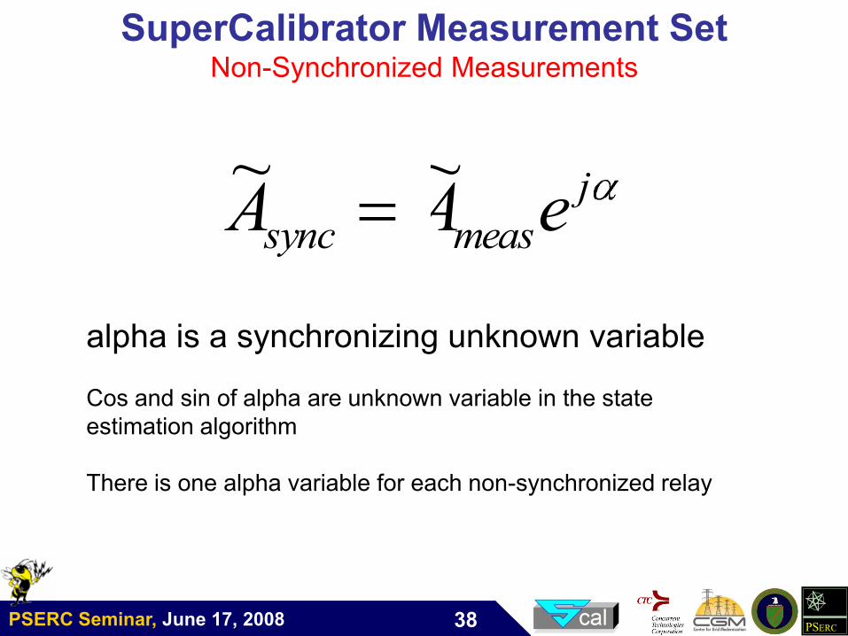
SuperCalibrator Measurement SetNon-Synchronized Measurements
j
meassync eAA~~
alpha is a synchronizing unknown variable
Cos and sin of alpha are unknown variable in the state
estimation algorithm
There is one alpha variable for each non-synchronized relay
PSERC Seminar, June 17, 2008 PSERC39
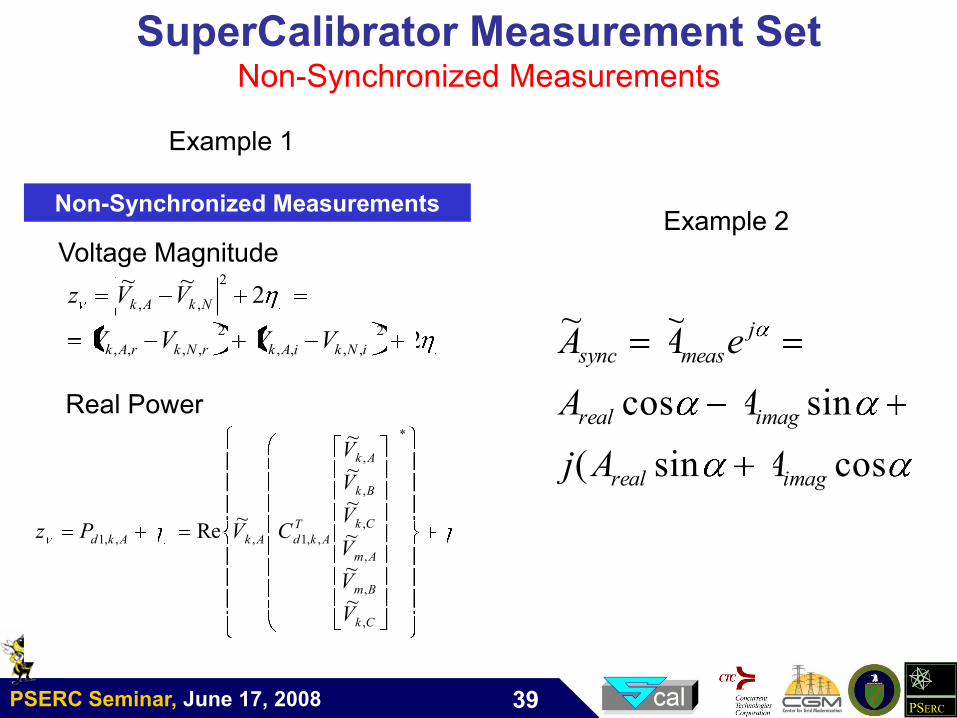
SuperCalibrator Measurement SetNon-Synchronized Measurements
2~~ 2
,, NkAk VVz
*
,
,
,
,
,
,
,,1,,,1
~
~
~
~
~
~
~Re
Ck
Bm
Am
Ck
Bk
Ak
T
AkdAkAkd
V
V
V
V
V
V
CVPz
Non-Synchronized Measurements
Real Power
Voltage Magnitude
22
,,,,
2
,,,, iNkiAkrNkrAk VVVV
cossin(
sincos
~~
imagreal
imagreal
j
meassync
AAj
AA
eAA
Example 1
Example 2
PSERC Seminar, June 17, 2008 PSERC40
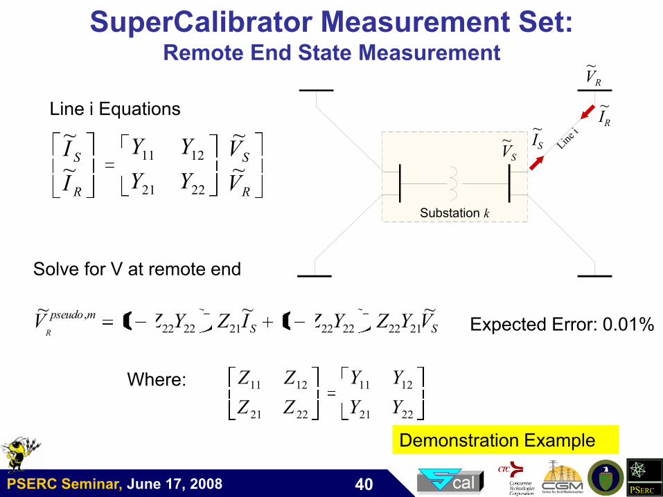
Substation k
IS
~IR
~
VS
~
VR
~
Line i
R
S
R
S
V
V
YY
YY
I
I~
~
~
~
2221
1211
SS
mpseudo VYZYZIZYZVR
~~~2122
1
222221
1
2222
,II
1
2221
1211
2221
1211
YY
YY
ZZ
ZZ
SuperCalibrator Measurement Set:Remote End State Measurement
Line i Equations
Solve for V at remote end
Where:
Expected Error: 0.01%
Demonstration Example
PSERC Seminar, June 17, 2008 PSERC41
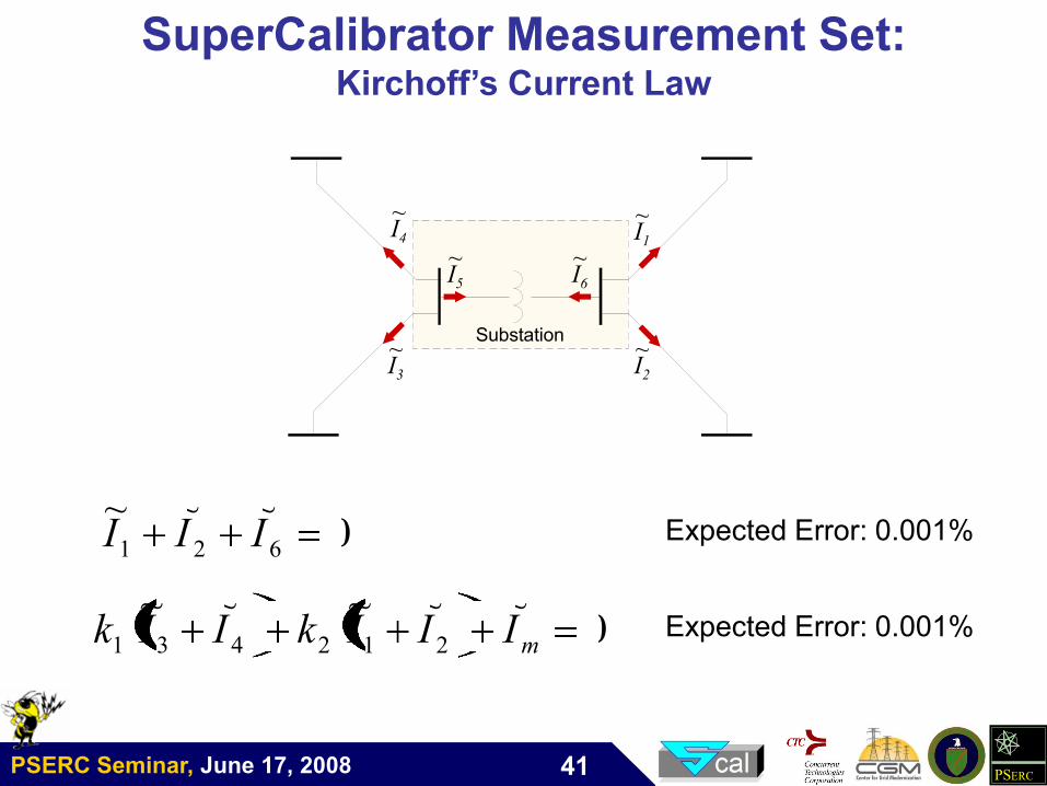
Substation
I4
~
I3
~
I5
~I6
~I1
~
I2
~
SuperCalibrator Measurement Set:Kirchoff’s Current Law
0~~~
621 III
0~~~~~
212431 mIIIkIIk
Expected Error: 0.001%
Expected Error: 0.001%
PSERC Seminar, June 17, 2008 PSERC42
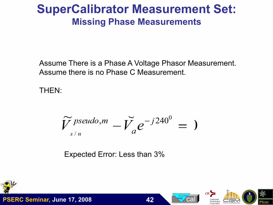
SuperCalibrator Measurement Set:Missing Phase Measurements
0~~ 0
/
240, j
a
mpseudo eVVns
Assume There is a Phase A Voltage Phasor Measurement.
Assume there is no Phase C Measurement.
THEN:
Expected Error: Less than 3%
PSERC Seminar, June 17, 2008 PSERC43
SuperCalibrator: Estimation Method
synnonphasor kkJMin
2222
*~~
~~~~,, NkAk VVz
~
~
~
~
~
~
~
~~
,
,
,
,
,
,
,,1,,1
Ck
Bm
Am
Ck
Bk
Ak
T
AkdAkd
V
V
V
V
V
V
CIz
2~~ 2
,, NkAk VVz
*
,
,
,
,
,
,
,,1,,,1
~
~
~
~
~
~
~Re
Ck
Bm
Am
Ck
Bk
Ak
T
AkdAkAkd
V
V
V
V
V
V
CVPz
GPS-Synchronized Measurements Non-Synchronized Measurements
Voltage Phasor
Current PhasorReal Power
Voltage Magnitude
22
,,,,
2
,,,, iNkiAkrNkrAk VVVV
PSERC Seminar, June 17, 2008 PSERC44
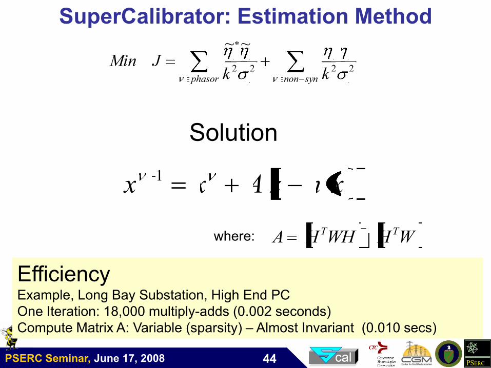
SuperCalibrator: Estimation Method
synnonphasor kkJMin
2222
*~~
Solution
xhzAxx 1
WHWHHA TT 1where:
EfficiencyExample, Long Bay Substation, High End PC
One Iteration: 18,000 multiply-adds (0.002 seconds)
Compute Matrix A: Variable (sparsity) – Almost Invariant (0.010 secs)
PSERC Seminar, June 17, 2008 PSERC45
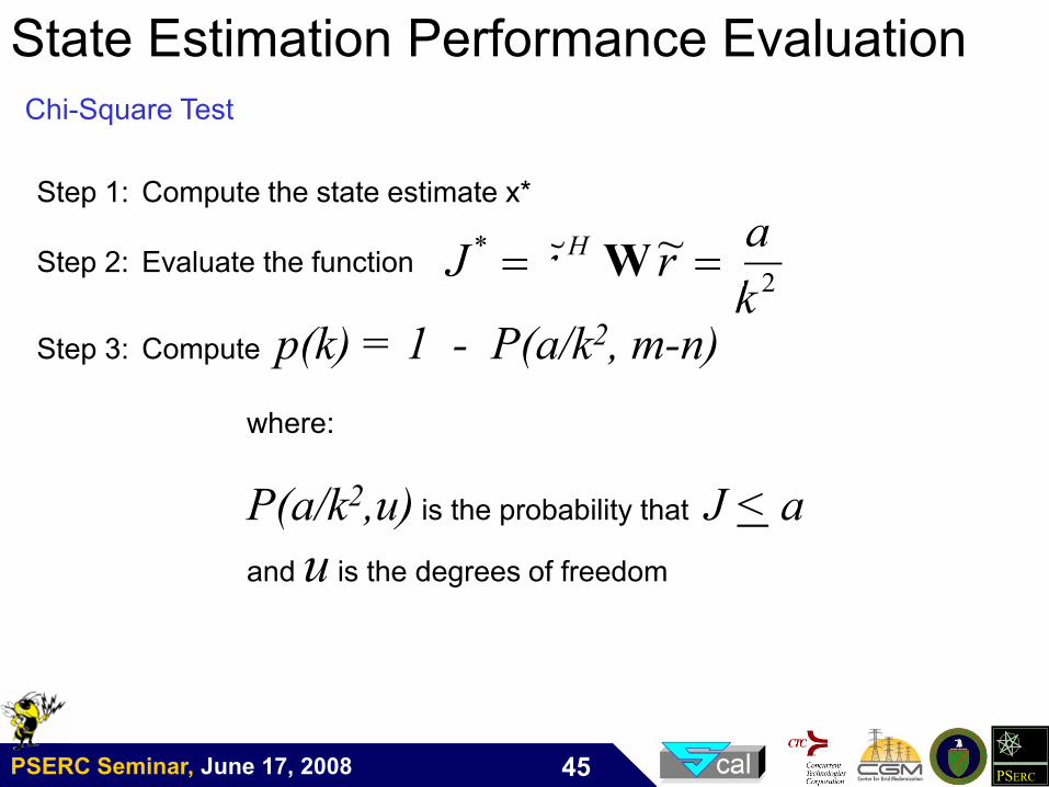
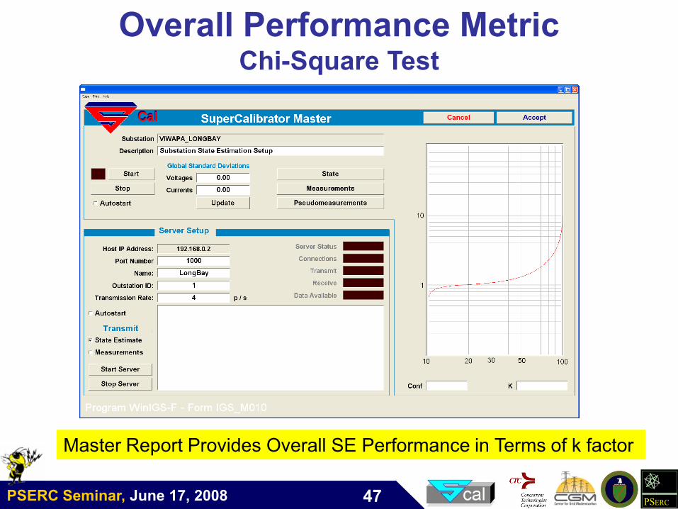
State Estimation Performance Evaluation
Chi-Square Test
Step 1: Compute the state estimate x*
Step 2: Evaluate the function
Step 3: Compute p(k) = 1 - P(a/k2, m-n)
where:
P(a/k2,u) is the probability that J < a
and u is the degrees of freedom
2
* ~~
k
arrJ H
W
PSERC Seminar, June 17, 2008 PSERC46
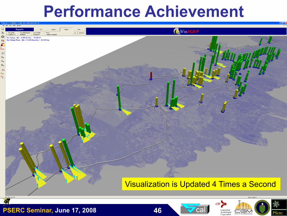
Performance Achievement
Visualization is Updated 4 Times a Second
PSERC Seminar, June 17, 2008 PSERC47
Overall Performance MetricChi-Square Test
Master Report Provides Overall SE Performance in Terms of k factor
PSERC Seminar, June 17, 2008 PSERC48
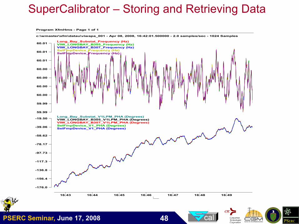
SuperCalibrator – Storing and Retrieving Data
Program XfmHms - Page 1 of 1
c:\wmaster\xfm\datau\viwapa_001 - Apr 08, 2008, 16:42:01.500000 - 2.0 samples/sec - 1024 Samples
16:43 16:44 16:45 16:46 16:47 16:48 16:49
59.99
59.99
60.00
60.00
60.00
60.00
60.01
60.01
60.01 Long_Bay_Substat_Frequency (Hz)VIW_LONGBAY_B305_Frequency (Hz)VIW_LONGBAY_B307_Frequency (Hz)SelFmpDevice_Frequency (Hz)SelFmpDevice_Frequency (Hz)
-176.0
-156.4
-136.8
-117.3
-97.73
-78.17
-58.62
-39.06
-19.50 Long_Bay_Substat_V1LPM_PHA (Degrees)VIW_LONGBAY_B305_V1LPM_PHA (Degrees)VIW_LONGBAY_B307_V1LPM_PHA (Degrees)SelFmpDevice_V1_PHA (Degrees)SelFmpDevice_V1_PHA (Degrees)
PSERC Seminar, June 17, 2008 PSERC49
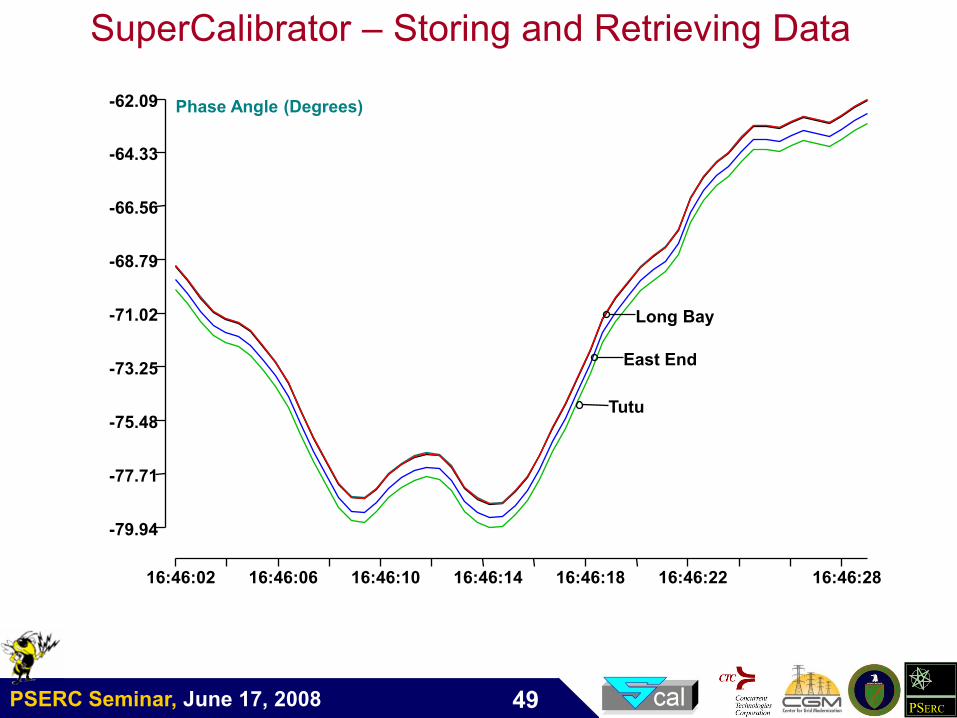
16:46:02 16:46:06 16:46:10 16:46:14 16:46:18 16:46:22 16:46:28
-79.94
-77.71
-75.48
-73.25
-71.02
-68.79
-66.56
-64.33
-62.09 Phase Angle (Degrees)
Tutu
Long Bay
East End
SuperCalibrator – Storing and Retrieving Data
PSERC Seminar, June 17, 2008 PSERC50
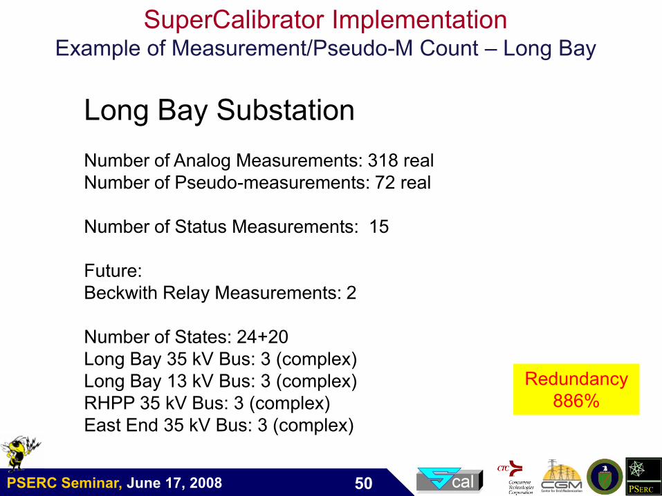
SuperCalibrator ImplementationExample of Measurement/Pseudo-M Count – Long Bay
Long Bay Substation
Number of Analog Measurements: 318 real
Number of Pseudo-measurements: 72 real
Number of Status Measurements: 15
Future:
Beckwith Relay Measurements: 2
Number of States: 24+20
Long Bay 35 kV Bus: 3 (complex)
Long Bay 13 kV Bus: 3 (complex)
RHPP 35 kV Bus: 3 (complex)
East End 35 kV Bus: 3 (complex)
Redundancy
886%
PSERC Seminar, June 17, 2008 PSERC51
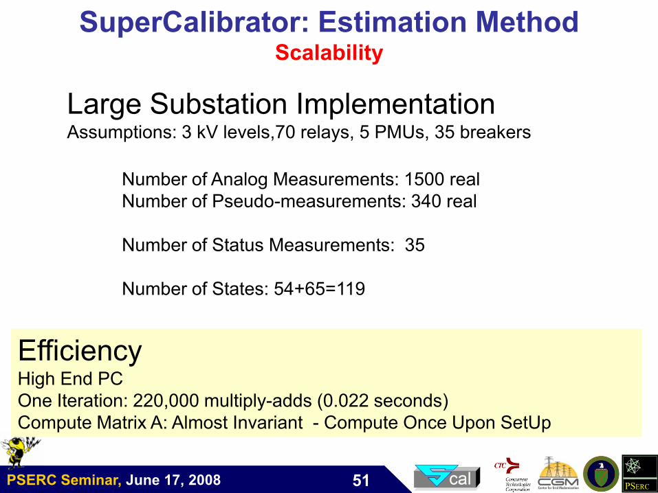
SuperCalibrator: Estimation MethodScalability
Large Substation ImplementationAssumptions: 3 kV levels,70 relays, 5 PMUs, 35 breakers
Number of Analog Measurements: 1500 real
Number of Pseudo-measurements: 340 real
Number of Status Measurements: 35
Number of States: 54+65=119
EfficiencyHigh End PC
One Iteration: 220,000 multiply-adds (0.022 seconds)
Compute Matrix A: Almost Invariant - Compute Once Upon SetUp
PSERC Seminar, June 17, 2008 PSERC52
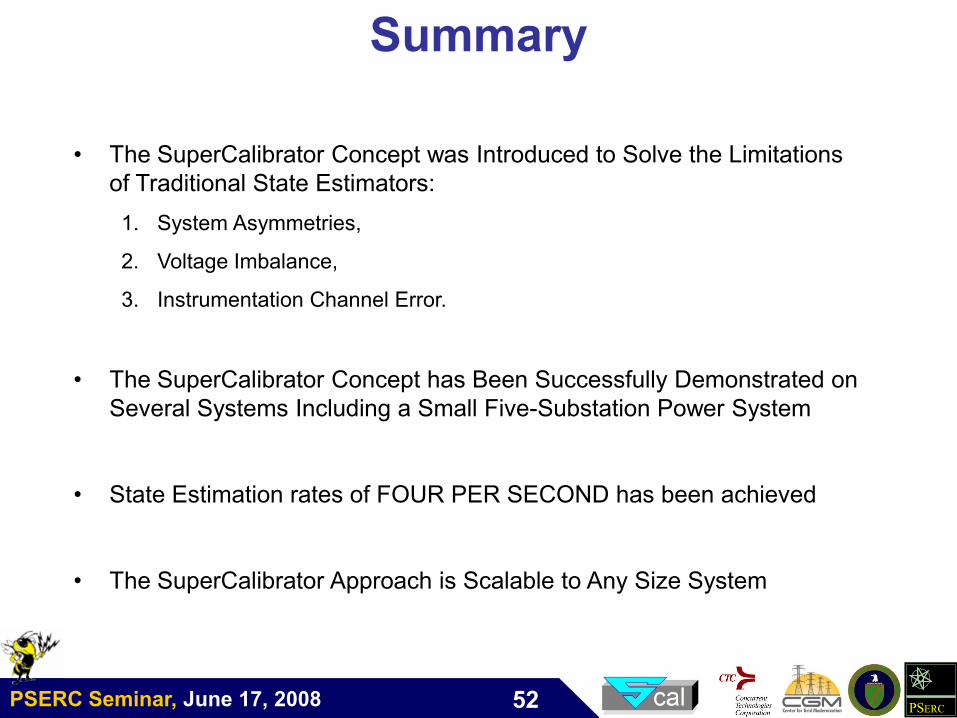
Summary
• The SuperCalibrator Concept was Introduced to Solve the Limitations
of Traditional State Estimators:
1. System Asymmetries,
2. Voltage Imbalance,
3. Instrumentation Channel Error.
• The SuperCalibrator Concept has Been Successfully Demonstrated on
Several Systems Including a Small Five-Substation Power System
• State Estimation rates of FOUR PER SECOND has been achieved
• The SuperCalibrator Approach is Scalable to Any Size System
PSERC Seminar, June 17, 2008 PSERC53
Future Directions
PSERC Seminar, June 17, 2008 PSERC54
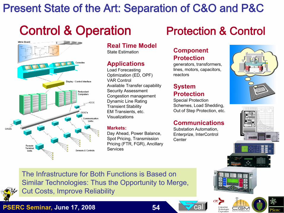
Real Time ModelState Estimation
ApplicationsLoad Forecasting
Optimization (ED, OPF)
VAR Control
Available Transfer capability
Security Assessment
Congestion management
Dynamic Line Rating
Transient Stability
EM Transients, etc.
Visualizations
Markets: Day Ahead, Power Balance,
Spot Pricing, Transmission
Pricing (FTR, FGR), Ancillary
Services
Present State of the Art: Separation of C&O and P&C
Control & Operation Protection & Control
The Infrastructure for Both Functions is Based on
Similar Technologies: Thus the Opportunity to Merge,
Cut Costs, Improve Reliability
Component
Protectiongenerators, transformers,
lines, motors, capacitors,
reactors
System
ProtectionSpecial Protection
Schemes, Load Shedding,
Out of Step Protection, etc.
CommunicationsSubstation Automation,
Enterprize, InterControl
Center
PSERC Seminar, June 17, 2008 PSERC55
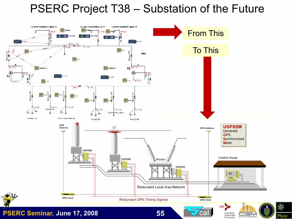
From ThisFrom This
To ThisTo This
PSERC Project T38 – Substation of the Future