pmse lte coexistence - apwpt coexistence ... for the lab measurements the ... a das network can be...
TRANSCRIPT

www.jrc.ec.europa.eu
Serving society
Stimulating innovation
Supporting legislation
PMSE – LTE Coexistence
Results of the JRC measurement session
of November 13-15, 2013

LTE-PMSE coexistence measurements
When: November 13-15, 2013
Where: JRC Radio Spectrum Laboratory, Ispra, Italy
Who: Experts from the PMSE industry, the GSMA, test equipment
manufacturers, and the JRC
2 18 February 2014

Test event objective
To evaluate whether the deployment of LTE small cells
operating in the 2600 MHz band in combination with
inter-band handover can protect PMSE systems operating
in the 821 - 832 MHz LTE duplex gap.
3 18 February 2014

PMSE in the LTE FDD Duplex Gap
Problem: Interference from LTE Out-Of-Band (OOB) emissions
4 18 February 2014
LTE band #20
791 MHz 821 MHz 832 MHz 862 MHz
10 MHz
FDD DL (BS) FDD UL (UE)
Duplex Gap
PMSE
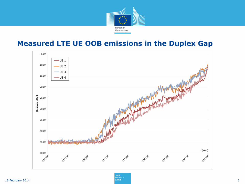
Measured LTE UE OOB emissions in the Duplex Gap
6 18 February 2014
-50,00
-45,00
-40,00
-35,00
-30,00
-25,00
-20,00
-15,00
-10,00
-5,00
UL
po
we
r [d
Bm
]
f [MHz]
UE 1
UE 2
UE 3
UE 4

PMSE-LTE coexistence – Current scenario
7 18 February 2014
LTE UE
LTE UE
LTE UE
LTE UL
LTE UL
LTE UL
FM Audio LTE Macro BS (800 MHz band)
LTE Macro BS (800 MHz band)
PMSE venue
Wireless microphone (800 MHz band)
PMSE receiver (800 MHz band)
- PMSE operates in the 821-832 MHz LTE duplex gap. - LTE UEs are registered with remote macro BS operating in the 832-862 MHz band. - Long distance => High path loss => High UL power => Adjacent channel interference to PMSE.

Potential solution: LTE Small cells and inter-band handover
8 18 February 2014
For reasons of simplicity small cells will be referred to as ‘picocells’ in this presentation
Source: Fujitsu, NSN
LTE cell types and their characteristics
Cell type Typical cell radius Transmit power range
[Typical value)
Deployment
location
Capacity
[no. of users)
Macro > 1 km 20 W - 160 W [40 W) Outdoor >256
Micro 250 m - 1 km 2 W - 20 W (5 W) Outdoor 64 - 256
< 100 m 100 mW - 250 mW Indoor 16 - 64
100 m - 300 m 1 W - 5 W Outdoor 16 - 64
10 mW - 250 mW Indoor 8 - 16
200 mW - 1 W Outdoor 8 - 32
Pico
Femto 10 m - 50 m
Base Station class Output power limit
Wide Area BS None
Medium Range BS ≤ 38 dBm (6.3 W)
Local Area BS ≤ 24 dBm (250 mW)
≤ 20 dBm (100 mW) [1 Tx antenna port]
≤ 17 dBm (50 mW) [2 Tx antenna ports]
≤ 14 dBm (25 mW) [4 Tx antenna ports]
< 11 dBm (13 mW) [8 Tx antenna ports]
Home BS
Source: ETSI TS 136 104 V11.6.0

PMSE-LTE coexistence – Possible future scenario
9 18 February 2014
- PMSE operates in the 821-832 MHz LTE duplex gap. - LTE UE have registered with on-site pico BS operating in the 2600 MHz band. - Frequency separation + low UL power => No interference to PMSE
LTE UE
LTE UE
LTE UE
LTE UL
LTE UL
LTE UL
FM Audio
LTE Pico BS (2600 MHz band)
LTE Pico BS (2600 MHz band)
PMSE venue
Wireless microphone (800 MHz band)
PMSE receiver (800 MHz band)
LTE Macro BS (800 MHz band)
LTE Macro BS (800 MHz band)
Coexistence measurements - Test cases
1. In operation
2. Start-up
10 18 February 2014
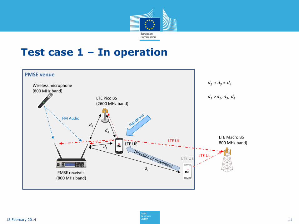
Test case 1 – In operation
11 18 February 2014
FM Audio
LTE Macro BS 800 MHz band)
PMSE venue
LTE UE
LTE Pico BS (2600 MHz band)
LTE UE LTE UL
d1
d3
d2
d4
d2 ≈ d3 ≈ d4
d1 > d2 , d3 , d4
Wireless microphone (800 MHz band)
PMSE receiver (800 MHz band)
LTE UL

In-operation test - Handover
12 18 February 2014
LTE UE Tx power received by the LTE pico BS
Time
PThresh3
PThresh2
PThresh1
Time
LTE UE UL centre frequency
837 MHz
2535 MHz
tDelay

Test case 2 – Start-up
13 18 February 2014
LTE UE
PMSE receiver (800 MHz band)
LTE Macro BS (800 MHz band)
PMSE venue
LTE Pico BS (2600 MHz band)
d1
d2
d3
d1 ≈ d2 ≈ d4
d3 >> d1 , d2 , d4
Wireless microphone (800 MHz band)
d4
FM Audio

Interference scenario
PMSE system operating at its sensitivity limit
Lowest possible RF signal level that produces a 30 dB SINAD (analogue receivers)
or the nominal SINAD (for digital receivers: 60 dB)
Signal levels between -91 and -102 dBm, corresponding to a maximum path
attenuation of 104 - 122 dB between wireless microphone and receiver
“Silent” PMSE test signal (3 kHz deviation)
PMSE squelch disabled
LTE UE traffic pattern simulating heavily varying uplink traffic
No Transmit Power Control
14 18 February 2014

What was measured?
Amount of LTE UE OOB emissions in the 821-832 MHz band
LTE centre frequency: 837 MHz
LTE channel width: 10 MHz (832-842 MHz)
Impact of LTE OOB emissions on PMSE audio signal quality (SINAD)
Potential interference effects caused by the LTE UE during and after
handover
Potential interference effects caused by the LTE UE during start-up and
BS selection
16 18 February 2014
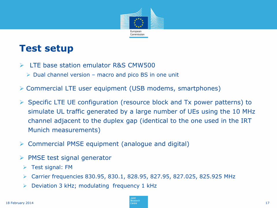
Test setup
LTE base station emulator R&S CMW500
Dual channel version – macro and pico BS in one unit
Commercial LTE user equipment (USB modems, smartphones)
Specific LTE UE configuration (resource block and Tx power patterns) to
simulate UL traffic generated by a large number of UEs using the 10 MHz
channel adjacent to the duplex gap (identical to the one used in the IRT
Munich measurements)
Commercial PMSE equipment (analogue and digital)
PMSE test signal generator
Test signal: FM
Carrier frequencies 830.95, 830.1, 828.95, 827.95, 827.025, 825.925 MHz
Deviation 3 kHz; modulating frequency 1 kHz
17 18 February 2014

Test setup – LTE USB modems / Analogue PMSE
18 18 February 2014
Channel 1LTE Macro BS800 MHz (LTE band 20)
Channel 2LTE Micro/Pico BS2600 MHz (LTE band 7)
ProgrammableAttenuator A1
RF combinerDirectional coupler
LTE UE
PMSE ReceiverAudio DAC
RF combiner
R&S CMW500
FM Signal generator
R&S SMU 200A
Ch 1
Ch 2
Uplink (800 MHz)
Agilent 11713B
Attenuator driver
Mini-CircuitsZN2PD2-63-S+
Mini-CircuitsZFRSC-123-S+
Agilent84904 + 84907
AtlanticA2023-20
Focusrite Scarlet 2i2
Spectrum analyzer
Tektronix RSA6114A
Timing reference
LP filter LPF2DC-1700 MHzMini-CircuitsVLF-1700+
RF combinerMini-Circuits
ZN2PD2-63-S+
RF combinerMini-Circuits
ZFRSC-123-S+
RF combinerMini-Circuits
ZFSC-2-372-S+
NI PXI
LTE spectrum &PMSE audio recorder
LTE BS emulator

In-operation measurements (1) Impact of LTE OOB emissions on analogue PMSE SINAD
20 18 February 2014
0
5
10
15
20
25
30
35
40
45
SINAD [dB]
Separation [dB]
Receiver A - 830.950 MHz Receiver A - 825.925 MHz Receiver B - 830.950 MHz Receiver B - 825.925 MHz

In-operation measurements (1) Impact of LTE OOB emissions on digital PMSE SINAD
21 18 February 2014
Receiver D - 825.925 MHz
Demonstration video – OOB Emissions
Impact of OOB emissions from LTE UE operating in the 832-842 MHz
band approaching an analogue PMSE receiver operating at 825.925 MHz.
22 18 February 2014
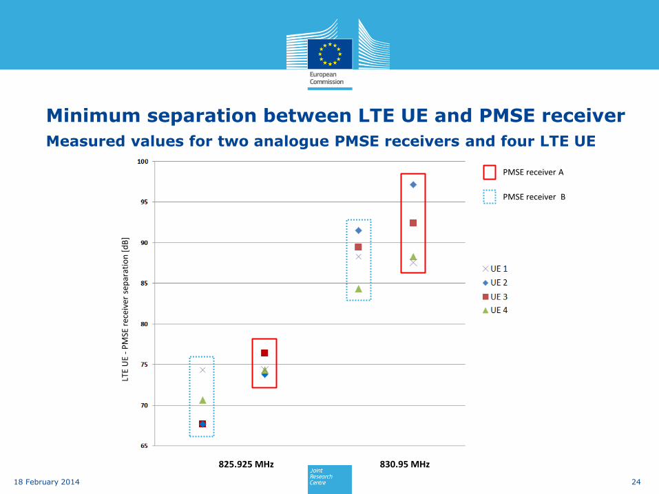
Minimum separation between LTE UE and PMSE receiver
Measured values for two analogue PMSE receivers and four LTE UE
24 18 February 2014
825.925 MHz 830.95 MHz
LTE
UE
- P
MSE
rec
eive
r se
par
atio
n [
dB
]
PMSE receiver A
PMSE receiver B

In-operation measurements (2) Handover
The LTE UE moves towards the
PMSE receiver.
Handover is initiated when the
power received from the LTE UE
reaches a certain threshold.
For the lab measurements the
handover was initiated at a
predefined separation between
LTE UE and PMSE receiver.
25 18 February 2014
0
5
10
15
20
25
30
35SINAD [dB]
Separation [dB]
830.950 MHz
827.950 MHzHandover

Demonstration video - Handover
Handover of an LTE UE approaching an analogue PMSE receiver
operating at 830.95 MHz.
26 18 February 2014

Interference measurements - Handover
Power measured in the 821-832 MHz band – No harmful interference detected
27 18 February 2014

Interference measurements - Start-up
Power measured in the duplex gap (821-832 MHz) during LTE UE startup.
Some low-level energy but no harmful interference detected.
28 18 February 2014
Results (1)
In-operation measurements – Impact of LTE OOB emissions
Close to the LTE band edge, all tested LTE UE generated harmful interference to
PMSE systems even at high path attenuations
At 830,950 MHz, the SINAD started decreasing at path attenuations between 81
and 97 dB => minimum [email protected] MHz = 97 dB
At 825,925 MHz, the SINAD started decreasing at path attenuations between 56
and 77 dB => minimum [email protected] MHz = 77 dB
29
18 February 2014

Results (2)
In-operation measurements - Handover
When a handover was initiated by the BS it was usually executed within less than
2 seconds.
In some cases, however, handover took a long time (more than 20 seconds). The cause of
the delay could not be determined.
When a handover was executed outside the protection range of the PMSE receiver
no interference was observed.
No harmful interference resulting from the LTE handover process itself could be
observed in the 821 – 832 MHz band.
In the dual-band PMSE scenario, no harmful interference resulting from the
handover process could be observed in the 1800 MHz band.
30 18 February 2014
Results (3)
Startup measurements
During multiple test runs the LTE UE always connected to the BS with the stronger
signal, in this case the pico BS operating at 2535 MHz.
No harmful interference in the 821-832 MHz band could be observed during the
start-up process.
31 18 February 2014
Conclusions
The negative impact of LTE OOB emissions on PMSE signal quality
identified in previous measurements (IRT, DKE, BNetzA, Ofcom, others)
was confirmed.
The utilisation of LTE picocells in combination with inter-band handover
can reduce interference from active LTE UE to PMSE if handovers are
executed outside the protection radius of the PMSE receivers.
The utilisation of LTE picocells operating in the 2600 MHz band can
reduce interference from LTE UE that are activated in the vicinity of a
PMSE receiver operating in the 800 MHz LTE duplex gap.
32 18 February 2014
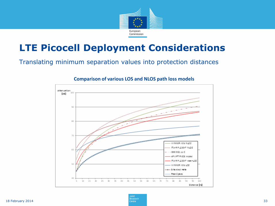
LTE Picocell Deployment Considerations
Translating minimum separation values into protection distances
33 18 February 2014
Comparison of various LOS and NLOS path loss models
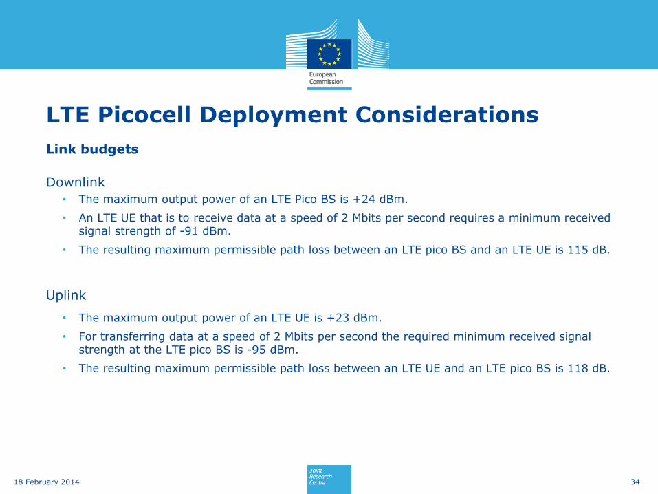
LTE Picocell Deployment Considerations
Link budgets
Downlink
• The maximum output power of an LTE Pico BS is +24 dBm.
• An LTE UE that is to receive data at a speed of 2 Mbits per second requires a minimum received signal strength of -91 dBm.
• The resulting maximum permissible path loss between an LTE pico BS and an LTE UE is 115 dB.
Uplink
• The maximum output power of an LTE UE is +23 dBm.
• For transferring data at a speed of 2 Mbits per second the required minimum received signal strength at the LTE pico BS is -95 dBm.
• The resulting maximum permissible path loss between an LTE UE and an LTE pico BS is 118 dB.
34 18 February 2014

LTE UE – PMSE separation distances
35 18 February 2014
825.925 MHz
830.950 MHz
97 dB
77 dB
PMSE receiver
LTE pico BS
115 dB
LTE UE
2535 MHz

Suggestions for further research and analysis
Practical implementation
Handover management
Reliability of LTE UE signal detection
Reliability and speed of inter-band handover
Intra-band handover between picocells
Pico cell capacity
Backhaul
Consider possible alternative solutions
Distributed Antenna Systems (DAS)
Local IP Access (LIPA)
36 18 February 2014
Distributed Antenna Systems (DAS)
37 18 February 2014
A DAS Network can be deployed outdoors or within large buildings and
partially enclosed structures, and a DAS Network can range from two to
hundreds of DAS Nodes.
Features small indoor antennas in various building locations.
Each DAS Node typically transmits RF signals at much lower power levels
than macro base stations.
Can be operated by 3rd party operator-independent companies
Especially used as multi-operator indoor coverage solution
Source: DAS Forum, Nokia Siemens Networks
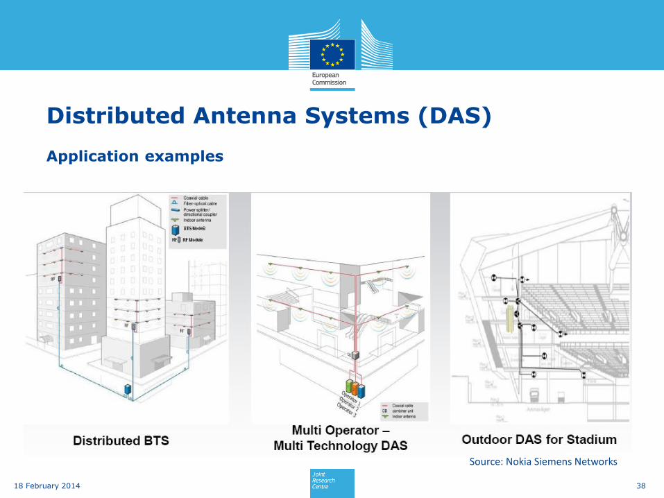
Distributed Antenna Systems (DAS)
38 18 February 2014
Application examples
Source: Nokia Siemens Networks

Local IP Access (LIPA)
Introduced in 3GPP rel. 9 and defined in 3GPP TR 23.829
Provides seamless interworking between LTE and WiFi.
Data traffic can be offloaded to WiFi while time-critical services such as
VoIP will be delivered via LTE.
39 18 February 2014


Backup slides
41 18 February 2014

Test case 3 – Multi-band PMSE
42 18 February 2014
FM Audio
LTE Macro BS 800 MHz band)
PMSE venue
LTE UE
LTE Pico BS (2600 MHz band)
LTE UL
Wireless microphone (1800 MHz band)
PMSE receiver (1800 MHz band)
Wireless microphone (800 MHz band)
PMSE receiver (800 MHz band)
FM Audio

Dual-band PMSE system measurement
Parallel operation of two PMSE systems (830 and 1800 MHz),
both operating at the respective receivers’ sensitivity limits.
Minimum distance between LTE UE and both PMSE receivers.
The audio signal of the 1800 MHz PMSE receiver was monitored while
multiple handovers from 837 to 2535 MHz were executed.
No interference could be observed.
43 18 February 2014

Test setup – LTE USB modems / Analogue PMSE
44 18 February 2014
Channel 1LTE Macro BS800 MHz (LTE band 20)
Channel 2LTE Micro/Pico BS2600 MHz (LTE band 7)
ProgrammableAttenuator A1
RF combinerDirectional coupler
LTE UE
PMSE ReceiverAudio DAC
RF combiner
R&S CMW500
FM Signal generator
R&S SMU 200A
Ch 1
Ch 2
Uplink (800 MHz)
Agilent 11713B
Attenuator driver
Mini-CircuitsZN2PD2-63-S+
Mini-CircuitsZFRSC-123-S+
Agilent84904 + 84907
AtlanticA2023-20
Focusrite Scarlet 2i2
Spectrum analyzer
Tektronix RSA6114A
Timing reference
LP filter LPF2DC-1700 MHzMini-CircuitsVLF-1700+
RF combinerMini-Circuits
ZN2PD2-63-S+
RF combinerMini-Circuits
ZFRSC-123-S+
RF combinerMini-Circuits
ZFSC-2-372-S+
NI PXI
LTE spectrum &PMSE audio recorder
LTE BS emulator

Test setup – LTE smartphones / Analogue PMSE
45 18 February 2014
Channel 1LTE Macro BS800 MHz (LTE band 20)
Channel 2LTE Micro/Pico BS2600 MHz (LTE band 7)
ProgrammableAttenuator A1
Directional coupler
LTE UE
PMSE ReceiverAudio DAC
RF combiner
R&S CMW500
FM Signal generator
R&S SMU 200A
Ch 1
Ch 2
Uplink (800 MHz)
Agilent 11713B
Attenuator driver
Mini-CircuitsZN2PD2-63-S+
Agilent84904 + 84907
AtlanticA2023-20
Focusrite Scarlet 2i2
Spectrum analyzer
Tektronix RSA6114A
Timing reference
LP filter LPF2DC-1700 MHzMini-CircuitsVLF-1700+
RF combinerMini-Circuits
ZN2PD2-63-S+
RF combinerMini-Circuits
ZFRSC-123-S+
RF combinerMini-Circuits
ZFSC-2-372-S+
Test fixtureLTE BS emulator
NI PXI
LTE spectrum &PMSE audio recorder

Test setup – LTE USB modems / Digital PMSE
46 18 February 2014

Test setup – Dual-band analogue PMSE
47 18 February 2014
Channel 1LTE Macro BS800 MHz (LTE band 20)
Channel 2LTE Micro/Pico BS2600 MHz (LTE band 7)
ProgrammableAttenuator A1
RF combinerDirectional coupler
LTE UE
Audio DAC
RF combiner
R&S CMW500
FM Signal generator (800 MHz)
R&S SMU 200A
Ch 1
Ch 2
Uplink (800 MHz)
Agilent 11713B
Attenuator driver
Mini-CircuitsZN2PD2-63-S+
Mini-CircuitsZFRSC-123-S+
Agilent84904 + 84907
AtlanticA2023-20
Focusrite Scarlet 2i2
Spectrum analyzer
Tektronix RSA6114A
Timing reference
RF combinerMini-Circuits
ZN2PD2-63-S+
RF combinerMini-Circuits
ZFRSC-123-S+
RF combinerMini-Circuits
ZFSC-2-372-S+
FM Signal generator (1800 MHz)
RF combinerMini-Circuits
ZN4PD1-63W-S+
PMSE Receiver800 MHz
PMSE Receiver1800 MHz
R&S SMBV 100A
LTE BS emulator
NI PXI
LTE spectrum &PMSE audio recorder
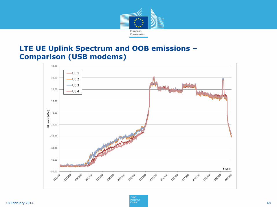
-50,00
-40,00
-30,00
-20,00
-10,00
0,00
10,00
20,00
30,00
40,00
UL
po
we
r [d
Bm
]
f [MHz]
UE 1
UE 2
UE 3
UE 4
LTE UE Uplink Spectrum and OOB emissions – Comparison (USB modems)
48 18 February 2014
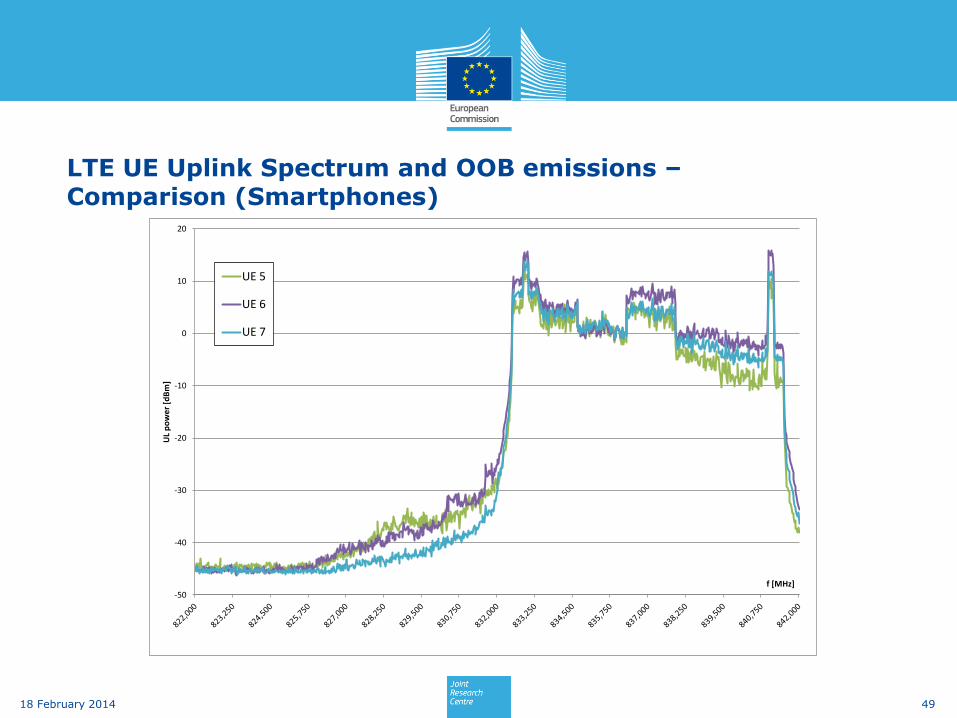
LTE UE Uplink Spectrum and OOB emissions – Comparison (Smartphones)
49 18 February 2014
-50
-40
-30
-20
-10
0
10
20
UL
po
we
r [d
Bm
]
f [MHz]
UE 5
UE 6
UE 7
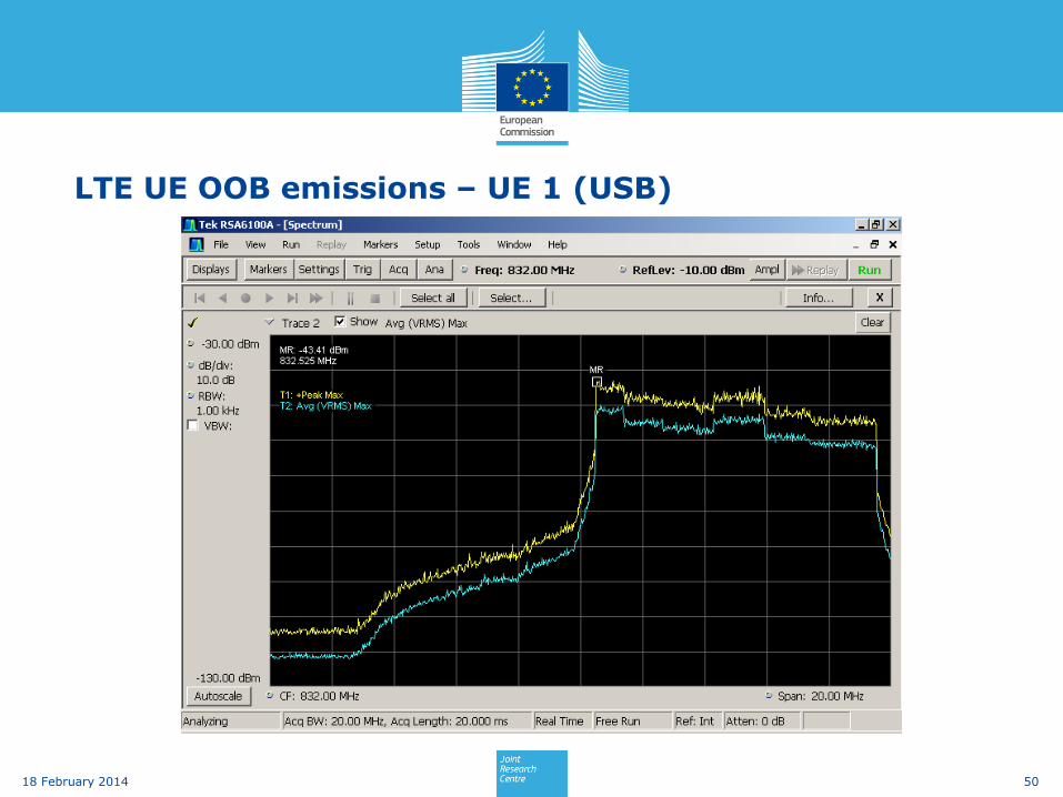
LTE UE OOB emissions – UE 1 (USB)
50 18 February 2014

LTE UE OOB emissions – UE 2 (USB)
51 18 February 2014
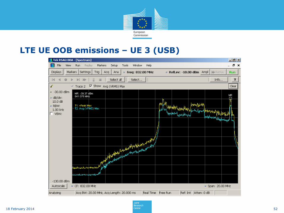
LTE UE OOB emissions – UE 3 (USB)
52 18 February 2014

LTE UE OOB emissions – UE 4 (USB)
53 18 February 2014

LTE UE OOB emissions – UE 5 (Smartphone)
54 18 February 2014

LTE UE OOB emissions – UE 6 (Smartphone)
55 18 February 2014

LTE UE OOB emissions – UE 7 (Smartphone)
56 18 February 2014

C-Message Filter
C-message weighting filter is a bandpass filter used to measure audio-
frequency noise on telephone circuits. The C-message filter is typically
used for North American telephone circuits.
57 18 February 2014
Source: Bell Systems. "Transmission Parameters Affecting Voice-band Transmission Measuring Techniques." Bell System Technical Reference, Pub. 41009, May 1975