pmcs system test simulator - ge grid solutions · multilin tm pmcs system test simulator pmcs...
TRANSCRIPT

MULTILIN TM
PMCS System TestSimulator
PMCS System Test SimulatorUser’s GuideGEH-6515
GE Power Management Control System 6.13

Notice
The information contained in this document is subject to change without notice. GE makes no warranty of anykind with regard to this material, including, but not limited to, the implied warranties of merchantability andfitness for a particular purpose. GE shall not be liable for errors contained herein or incidental consequentialdamages in connection with the furnishing, performance, or use of this material.
This document contains proprietary information, which is protected by copyright. All rights are reserved. Nopart of this document may be photocopied or otherwise reproduced without consent of GE.
Copyright ©2001 - 2004 by GE
Published in a limited copyright sense, and all rights including trade secrets, are reserved.
Document Edition - First 05/96Second 05/97Third 05/98Fourth 03/00Fifth 02/01, Sixth 01/02, Seventh 01/04, Eigth 09/04
The following are products of General Electric Company:POWER LEADERTM Meter Power Quality Meter (PQM), GE Fanuc Series 90/30 PLCPOWER LEADER Modbus Monitor 239 Motor Protection Relay GE Fanuc Series 90/70 PLCPOWER LEADER Electronic PowerMeter
269 Plus Motor Management Relay GE Fanuc MicroPLC
Spectra MicroVersaTrip 369 Motor Management Relay Enhanced MicroVersaTrip-C SR469 Motor Management Relay Enhanced MicroVersaTrip-D SR489 Generator Management Relay
MDP Overcurrent Relay 565 Feeder Management Relay 735 Feeder Relay EPM 3710 Electronic Power Meter
Spectra Electronic Control Module SR745 Transformer Management Relay EPM 3720 Electronic PowerMeter
Universal Relay devices SR750 Feeder Management Relay EPM 7300 Electronic PowerMeter
SR760 Feeder Management Relay
Multilin 269+ Motor Management Relay® are registered trademarks of Multilin Inc., and Multilin SR489 Generator Management Relay™ and Multilin SR745Transformer Management Relay™ are trademarks of Multilin Inc.
Microsoft, Microsoft Access, Microsoft Excel, and Microsoft PowerPoint are registered trademarks, andWindows NT is a trademark of Microsoft Corporation.
NetDDE is a trademark of WonderWare Corporation.
US Pat Nos 5,768,148; 5,764,155; 5,862,391

PMCS System Test Simulator Contents •••• i
Back to Main Menu
Contents
Introduction 1Welcome ....................................................................................................................................1Basic Concepts ...........................................................................................................................2
DDE .............................................................................................................................2NetDDE .......................................................................................................................3PMCS DDE Server ......................................................................................................3Client Applications ......................................................................................................4
About the System Test Simulator ...............................................................................................5Devices Supported by the System Test Simulator........................................................5Who uses the System Test Simulator? .........................................................................6What is the System Test Simulator used for?...............................................................6Why use the Simulator rather than the real DDE Server? ............................................6Features........................................................................................................................6Applicable Documents.................................................................................................7
Installation Instructions ..............................................................................................................7System Requirements...................................................................................................7Directory Structure.......................................................................................................7
Menu Conventions .....................................................................................................................8
Quick Start 9Introduction................................................................................................................................9Launching the Program ..............................................................................................................9Setting up a Simulation ............................................................................................................10Setting up DDE Requests from Client Applications.................................................................16
The Device Simulator 17Introduction..............................................................................................................................17Start-up.....................................................................................................................................17Simulator Screen Controls........................................................................................................20
Title Bar .....................................................................................................................20Command Bar ............................................................................................................20Device Selector ..........................................................................................................21Meter Values..............................................................................................................21

ii •••• Contents PMCS System Test Simulator
Register Details ......................................................................................................... 23Defining Device Profiles ......................................................................................................... 25Defining Events and Special Commands................................................................................. 27
Events........................................................................................................................ 27Special Commands.................................................................................................... 28

PMCS System Test Simulator Contents •••• iii
DDE Server Menus & Toolbars 29Screen Navigation ....................................................................................................................29
Menu Bar ...................................................................................................................30Toolbar.......................................................................................................................30Minimize Icon............................................................................................................30
System Menu............................................................................................................................31Server Menu.............................................................................................................................31
Switch to Simulator / Run ..........................................................................................31Stop............................................................................................................................32Suspend Protocol/Resume Protocol ...........................................................................32Exit.............................................................................................................................32
Configure Menu .......................................................................................................................33Ports ...........................................................................................................................33Device Info ................................................................................................................35Device Type Information ...........................................................................................37Operational Parameters..............................................................................................37
Reports Menu...........................................................................................................................38Configuration .............................................................................................................38Active Links...............................................................................................................38
Help Menu................................................................................................................................39Toolbar.....................................................................................................................................39
Troubleshooting 41Trouble-shooting the PMCS System Test Simulator................................................................41
WWLogger ................................................................................................................41Communications – Client to Server..........................................................................................41NetDDE Troubleshooting ........................................................................................................43Trouble-Shooting Chart............................................................................................................43Error Messages.........................................................................................................................44
Advanced Topics 47Introduction..............................................................................................................................47Device Type Information – Adding Generic Devices .............................................................47
Add Default Type ......................................................................................................48Delete.........................................................................................................................49Function Codes ..........................................................................................................49Register Map..............................................................................................................50Mnemonics.................................................................................................................54
Optimizing Server Performance ...............................................................................................56Operational Parameters..............................................................................................56PMCS DDE Server .ini File.......................................................................................57
Appendix A - Register Addressing Conventions 59Data-Addressing Conventions..................................................................................................59
Standard Data Organization .......................................................................................60Special Naming Conventions .....................................................................................61Register Array Format................................................................................................62
Index 65

PMCS System Test Simulator Introduction •••• 1
Introduction
WelcomeGE’s Power Management Control System (PMCS) is a supervisory management andcontrol system (SCADA) for industrial or institutional electrical distribution systems.These systems can be complex and costly to build, involving large amounts ofcabling and many power management devices, such as meters and trip units. Withsuch high overhead involved, you can see the importance of being able to model andtest such a system prior to physical construction and installation.
The GE PMCS System Test Simulator answers this need. The System Test Simulatoris a PC-based tool for developing and configuring the software interface of thePMCS DDE Server, then testing it with client applications. The System TestSimulator makes it possible to model an entire power management system insoftware, without ever connecting a physical device.
The Simulator plays the role of every power management device attached to themodel system, generating appropriate data, events, and responses to the requests ofthe PMCS DDE Server, which in turn passes the data to the requesting clientapplications. The client applications requesting data from the PMCS DDE Server arecompletely unaware that the data they are receiving are not coming from a real powermanagement network.
The figures below Figure 1 and Figure 2 illustrate the differences between a realPMCS network and one running the PMCS System Test Simulator.
PMCSDDE Server
PMCS clienton networked PC
Modbus RTU communications network
Device
...
Device Device
NetDDEcommunications
Host PC
PMCSclient
PMCS clienton networked PC
DDEcommunications
DDEcommunications
PMCSclient
Figure 1. Example of PMCS system with real devices.

2 •••• Introduction PMCS System Test Simulator
The first figureFigure 1 shows an example of a real PMCS network. Clientapplications request device data from the PMCS DDE Server via DDE or NetDDEcommunications. The PMCS DDE Server collects the data from the powermanagement devices, then replies to the clients.
PMCSSystem Test
Device Simulator
PMCS clienton networked PC
PMCS SystemTest Simulator
DDE Server
DDEcommunications
NetDDEcommunications
PMCSclient
PMCS clienton networked PC
DDEcommunications
DDEcommunications
PMCSclient
Host PC
Figure 2. Example of PMCS System Test Simulator.
In the second figureIn Figure 2, the client applications request device data from thePMCS DDE Server, just as in a real PMCS network. However, the System TestSimulator uses a special PMCS DDE Server that has been modified to collect its datafrom the Device Simulator program, rather than from a network of devices. The DDEServer requests the desired data from the Device Simulator, which generates arealistic simulation of data for the appropriate device type. The DDE Server repliesto the client applications, which are unaware that the data has not come from realpower management devices.
Basic Concepts
DDEDDE is the acronym for Dynamic Data Exchange, a communications protocol thatallows independently developed MS Windows programs to share data andinstructions with each other.
DDE implements a client-server relationship between two concurrently runningprograms. The server application provides data and accepts requests from any otherapplications interested in its data. The applications requesting the data are calledclients.
Requests for data can be of two types: one-time requests or permanent data links.With one-time requests, the client program requests a “snapshot” of the desired datafrom the server application. An example of a one-time request is a program, such asExcel, running a report-generating macro. The macro opens a temporary link toanother application, requests specific data, closes the link, then uses the data togenerate the report.
PMCS System Test Simulator Introduction •••• 3
Permanent data links are called “hot links.” When a client application sets up a hotlink to another application, it requests the server application to advise the clientwhenever a specific parameter changes. Hot links remain active until either the clientor server program terminates the link. Hot links are an efficient means of exchangingdata because, once the link has been established, no communication occurs until thespecified parameter changes.
The DDE protocol specification includes standardized formats for messages to beexchanged between DDE-compliant applications (such as Microsoft Excel).
NetDDENetDDE for Windows NT is an extension to DDE. With NetDDE, client applicationsdo not have to be running on the same PC as the DDE Server; a client application onone PC may request data from a DDE Server operating on another PC. Itscapabilities include communication over local-area networks and through serial ports.
Two or more networked PCs running Windows NT are required to run NetDDE. Theversion of NetDDE that is supplied with Windows NT is the recommended version;other versions of NetDDE are not recommended for use with PMCS.
PMCS DDE ServerThe PMCS Dynamic Data Exchange (DDE) Server is the heart of a POWERLEADERTM Power Management Control System (PMCS), a tool that helps youincrease productivity, reduce downtime, and improve power quality by automaticallycollecting the wealth of data available from devices in your power network. Youselect data to monitor, configure the PMCS DDE Server to communicate with theselected devices in your system, and the PMCS DDE Server collects the requesteddata and supplies it to your choice of software applications for analysis and trending.
NOTE: The DDE Server supplied with the System Test Simulator is a modifiedversion of the PMCS DDE Server. Instead of collecting data from powermanagement devices, it collects data from a special software application called theDevice Simulator, which supplies the DDE Server with realistic data to pass toclients.
Apart from collecting its data from the Device Simulator rather than from realdevices, the Simulator’s DDE Server and the real PMCS DDE Server arefunctionally identical, even using the same configuration files. After setting up aPMCS network on the System Test Simulator you can immediately use the sameconfiguration simply by launching the real PMCS DDE Server.
Because of this tightly integrated design, you should also keep in mind that anychanges you make using the System Test Simulator will apply to the real PMCS DDEServer.
The PMCS DDE Server collects metering, status, event, and alarm data frommetering, control, and protection devices on the network, or from the PMCS SystemTest Simulator. The Server then communicates this data to PMCS software clients,such as the third-party HMI tools or the PMCS Event Logger. The data can easily beimported into spreadsheets such as Microsoft Excel for analysis and presentation.

4 •••• Introduction PMCS System Test Simulator
The PMCS DDE Server supports both DDE for sharing data with applications on thesame computer and NetDDE for sharing data with other computers in a local-areanetwork (LAN).
Client ApplicationsClient applications request specific data from the PMCS DDE Server and thenprovide calculations, trending, and display of the data on screen and/or printer.
Various client applications are available to serve different needs. Event Logger is anexample of client applications that are fully optimized for PMCS.
Any DDE-compliant application can request data from the PMCS DDE Server byinitiating a “conversation” with the server and providing the correct informationphrased in DDE format—i.e., what data from which device.
Other common DDE-compliant applications used to analyze data from the PMCSDDE Server are Microsoft Excel and Microsoft Access, both providing data-manipulation and analysis tools. However, any DDE-compliant application mayretrieve data from thefS DDE Server. For instance, a presentation on the powerconsumption at an industrial facility can be created using Microsoft PowerPoint,retrieving and graphing power consumption data from the PMCS DDE Server.

PMCS System Test Simulator Introduction •••• 5
About the System Test SimulatorThe PMCS System Test Simulator consists of two primary applications and severalsupport applications. The support applications are discussed later. For now, we areonly concerned with the primary applications: the Server and the Device Simulator.
The Server is a modified version of the PMCS DDE Server (Modbus version;Ethernet simulations are not supported by the System Test Simulator), which hasbeen programmed to retrieve data from the Device Simulator rather than from anetwork of power management devices. The Device Simulator serves as areplacement for the network of power management devices, pretending to bewhatever devices we’ve told it to represent. The Device Simulator responds to theServer’s data queries by supplying data that accurately emulates data from realdevices.
Devices Supported by the System Test Simulator
Pre-installed GE proprietary devicesThe PMCS Simulator contains pre-installed profile data for the devices supported byPMCS 6.9.
NOTE: The Simulator supports some of the functions of the PMCS 6.9 devices. It isnot intended to be a compete simulation of all device functions nor a simulation ofdevice interaction or network behavior. For instance, increasing the voltage at onedevice will not cause the voltage at another device to increase, as it might in a realsystem. Command coils are not supported for most device types, nor is the generationof waveform data.
Generic devicesThe Simulator also supports a customizable generic device type, capable of register-based communications with Modbus RTU.
Usually, a generic device is a third-party power management device requiring customconfiguration to work with the PMCS DDE Server. The Simulator can be configuredto support generic device types; instructions are provided in Advanced Topics.
Several GE devices, such as the family of PLCs, are designed to be so flexible thatthey also can be considered generic devices, requiring special configuration.

6 •••• Introduction PMCS System Test Simulator
Who uses the System Test Simulator?• System integrators and developers can use the Simulator for
development and preliminary testing of PMCS supervisory control anddata acquisition (SCADA) systems for electrical distributioncomponents, metering, and monitoring.
• Marketing and sales engineers can use the Simulator for demonstrationof PMCS systems without connecting to an actual network of devices.
What is the System Test Simulator used for?Some of the practical uses of the System Test Simulator are as follows:
• To build a model of a PMCS system, including planned devices andDDE Server Software.
• To test the DDE Server’s interface and DDE links between the DDEServer and client applications.
• To test custom-designed Human-Machine Interfaces (HMIs), verifyingthe links between custom wizards and the DDE Server registers.
• In third-party HMI design tools, to validate the logic of the one-linediagram (electrical representation of the system). In the DDE Simulator,to create pseudo-device names and PLC I/O points to test against theDDE Server.
Why use the Simulator rather than the real DDEServer?Using the Simulator provides the following benefits:
• It allows system developers to debug the DDE links in the DDEinterface software off-site, prior to full system installation.
• It reduces the time needed for development and on-site testing of thesystem.
• It eliminates disruptions of the customer operating system or facility.
Features• User-configurable power-simulation profiles and topic setup
parameters.
• Pre-installed registers for all GE device parameters.
• Pre-installed values for many dynamic value registers (GE devices).
• Consistent device event and trip simulation for dissimilar devices.
• Generic support for any Modbus RTU-compliant device.
• Easy to use, Windows-based graphical user interface with a toolbar andpull-down menus for quick and easy device definition, configuration,and report generation.

PMCS System Test Simulator Introduction •••• 7
Applicable Documents• GEH-6502, PMCS Network Architecture Guide
• GEH-6510, PMCS Network and Device Configurator Users’ Guide
• GEH-6509, PMCS DDE Server Interface Reference
• GEH-6508, Modbus Concentrator Protocol Reference
Installation InstructionsFor installation instructions, refer to GEH-6514, Read This Book First, whichcontains installation procedures for all POWER LEADERTM system and applicationsoftware packages.
In order to fully test your system, you may need to install additional software,including the PMCS system, Microsoft Office, and third-party HMI developmenttools.
System RequirementsRefer to GEH-6514, PMCS Read This Book First, for system requirements to run thePMCS System Test Simulator.
Directory StructureInstalling the PMCS Simulator software creates the following directory on the harddrive, where X is the drive letter:
X:\ge_pmcs\sim\
You should know where the files are located on your hard drive so that you do notaccidentally move or erase them. In addition, you may want to make changes to thesefiles in the testing process.
8 •••• Introduction PMCS System Test Simulator
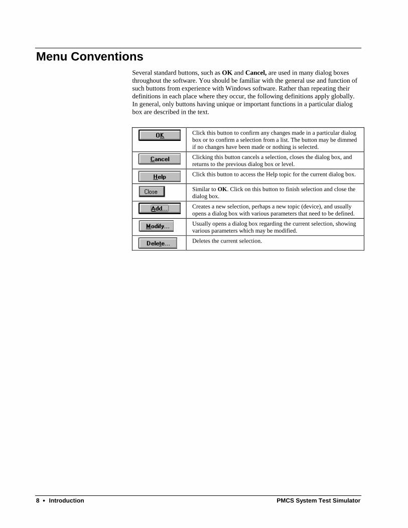
Menu ConventionsSeveral standard buttons, such as OK and Cancel, are used in many dialog boxesthroughout the software. You should be familiar with the general use and function ofsuch buttons from experience with Windows software. Rather than repeating theirdefinitions in each place where they occur, the following definitions apply globally.In general, only buttons having unique or important functions in a particular dialogbox are described in the text.
Click this button to confirm any changes made in a particular dialogbox or to confirm a selection from a list. The button may be dimmedif no changes have been made or nothing is selected.
Clicking this button cancels a selection, closes the dialog box, andreturns to the previous dialog box or level.
Click this button to access the Help topic for the current dialog box.
Similar to OK. Click on this button to finish selection and close thedialog box.
Creates a new selection, perhaps a new topic (device), and usuallyopens a dialog box with various parameters that need to be defined.
Usually opens a dialog box regarding the current selection, showingvarious parameters which may be modified.
Deletes the current selection.

PMCS System Test Simulator Quick Start •••• 9
Quick Start
IntroductionIn this section, we’ll demonstrate the basic functions of the PMCS System TestSimulator software and walk through the most commonly used menus and commandsof the program.
This section provides a tutorial rather than a comprehensive reference. Sections 3 and4, The Device Simulator and DDE Server Menus and Toolbars, of the User’s Guideoffer in-depth descriptions of the menus and functions of the Device Simulator andDDE Server respectively.
Before working with the PMCS System Test Simulator, you should plan yournetwork on paper, diagramming the RS-485 communications networks, the devicesassigned to each network, and the Modbus address assigned to each device. Forinformation on how to design a PMCS network, refer to GEH-6502, PMCS NetworkArchitecture Guide.
Launching the ProgramTo start the PMCS System Test Simulator, open the GE PMCS program group inWindows. The Simulator program icon is shown below. Launch the application fromthe Windows Start menu or by double-clicking on the icon.
Launching the System Test Simulator also starts several supporting applications: theSimulator’s specially-modified DDE Server and the Graphics Server. All of thesepieces work together to provide the simulated devices for client applications.
Note: The PMCS System Test Simulator is designed to simulate only Modbus-basedPMCS networks. Simulation of Ethernet-based PMCS systems is not supported bythe System Test Simulator. However, you can use the Simulator with clients set foran Ethernet DDE Server by changing the Server name referenced by the clientapplications. In your client application, change any references to GE32ENET (theEthernet DDE Server) to GE32MODB (the Modbus DDE Server/Simulator).

10 •••• Quick Start PMCS System Test Simulator
When launched, the Simulator prompts you to load profile data and register map datafrom a file. If you have previously saved profile data or register map data that youwant to continue working with, go ahead and select the data file to load. If you aresetting up a new system simulation, click NO and proceed.
Setting up a SimulationThe PMCS Simulator generates data in response to requests from the DDE Server.The Simulator’s responses are based on the device type associated with the DDErequest; when you request data from an MDP Overcurrent Relay, that’s what you getback.
Before the simulation can occur, you must tell it specifically which devices you wantto include in your particular system. Therefore, the first step in setting up asimulation is to configure the devices you want to simulate. We’ll walk throughsetting up a device to demonstrate the procedure.
To begin this exercise, you should be looking at the main window of the Simulator’sDDE Server:

PMCS System Test Simulator Quick Start •••• 11
If you’re looking at the Device Simulator window (shown below), click the Serverbutton to switch to the Server window.
We’ll configure a single device and explain how to access its data from a clientapplication. Once you’ve learned the basics of configuring a device, you’ll be readyto set up simulations of more involved networks. Later, we’ll show you how tocustom-configure generic devices and perform advanced Server configuration.
From the Server window’s menu bar, pull down the Server menu and select Stop,unless it is already grayed out. The Server must be Stopped before any deviceconfiguration can be performed. (Clicking the stop sign button on the toolbarperforms the same action as selecting Stop from the Server menu.)

12 •••• Quick Start PMCS System Test Simulator
Pull down the Configure menu and select Configure (the only option on the menu).
This will bring up the Configuration dialog box, offering four options:
• Ports…
• Operational Parameters…
• Device Type Info…
• Device Info…
Ignore the Operational Parameters… and Device Type Info… buttons for the timebeing–these are advanced options that will be discussed later. We’ll first configure acommunications port, then configure a device assigned to that port.
To configure a communications port, click the Ports button. and theCommunication Port Configuration dialog box is displayed:

PMCS System Test Simulator Quick Start •••• 13
Select the communication port to configure from the COM Port pull-down list at thetop of the dialog box.
Select the appropriate radio button for each of the communication settings: Parity,Stop Bits, Flow Control, and Baud Rate. The default settings are shown. Typically,only the baud rate need be changed to match the baud rate of the devices connectedto the comm port. The rest of the communication settings are standard. Refer to theuser manuals of the individual devices to be sure the communication settings match.
Click on OK to return to the Configure dialog box—our first com port has beensuccessfully configured.
Hint: You don’t need to leave the Communication Port Configuration dialog box toconfigure multiple ports. Select a port from the pull-down list, make your changes,then you can select another port from the pull-down list and configure it as well.Configure as many ports as you need to, then click OK to save your changes andreturn to the Configure dialog box.
Next, we’ll configure a sample device.

14 •••• Quick Start PMCS System Test Simulator
Click the Device Info button. This will bring up the Device Configuration dialogbox, displaying a list of configured devices and options to Add, Modify or Deletedevices.
We want to add a device, so click the Add button. The Add Device Configurationdialog box appears:

PMCS System Test Simulator Quick Start •••• 15
In the Device Name (Topic) field, enter the name by which you’ll reference thisdevice from a client application. The device name should be unique, have fewer than20 characters, and contain no special characters (the program won’t allow you toenter any, so this part is easy).
Select a device type from the Device Type pull-down list. For this exercise, select anMVT (MicroVersaTrip trip unit). Selecting the type of device, such as Spectra ECMor POWER LEADER EPM, tells the DDE Server what kind of register map to expectand tells the Device Simulator what kind of register map to use in simulating thisdevice. (Details of PMCS device register maps can be found in GEH-6508, thePMCS DDE Server Interface Reference.)
Select the com port this device is attached to.
Enter a valid slave address; this is the Modbus address of the device. You shouldhave this information on the network diagram you drew earlier.
The address selected must adhere to the following rules:
• For Modbus Concentrators, the slave address must be between 1 – 32.
• commnet devices must have slave addresses in the range33 – 247
• Modbus-based devices may have any address from 1 – 247
If you’re not sure whether a device is commnet- or Modbus-based, or you havequestions regarding commnet and Modbus, refer to GEH-6502, PMCS NetworkArchitecture Guide.
The Scan Interval field should be left set at 1000. We’ll discuss Scan Interval lateron.
Last, click the OK button to accept your entries, close the dialog box, and return tothe Device Configuration dialog box.
Make sure the Activate checkbox is selected, or the Server will not recognize thedevice. This feature is a useful way to quickly disable individual devices.
Click Close and Restart Server to exit Configuration and begin using the device.You’ll return to the Device Simulator window and view the default data beinggenerated to simulate the device you just configured.
The Server now recognizes the device, so when a client application requests datafrom the device, the Server will retrieve the data from the Device Simulator andrespond to the client’s query.

16 •••• Quick Start PMCS System Test Simulator
That’s the procedure for configuring any supported GE device. Configurationprocedures for “generic” devices such as non-supported third-party devices, andhighly customizable GE Fanuc Programmable Logic Controllers, are covered inSection 6, Advanced Topics.
Setting up DDE Requests from Client ApplicationsTo obtain data from a device on the System Test Simulator, a client opens a channelto the DDE Server by specifying these three names:
<application name> <topic name> <item name>
<application name> – the name of the Server program.
<topic name> – the name given to the field device, such as EPM1 for a device of typeEPM.
<item name> – The actual address of the field parameter to be monitored—a specificvalid register address or group under topic EPM1, such as R34001, or mnemonic,such as Amps_A.
For register and item names and examples of DDE protocol, refer to GEH-6509,PMCS DDE Server Interface Reference. An example is provided which demonstratesthe use of a spreadsheet to link to a DDE item in the Server or Simulator.
Refer to documentation of your client program for details on defining a DDE item inthe client.

PMCS System Test Simulator The Device Simulator •••• 17
The Device Simulator
IntroductionWith the overview of device setup behind us, we’ll now take a closer look at theDevice Simulator.
As we mentioned earlier, the System Test Simulator has two major components, theDDE Server and the Device Simulator. The DDE Server is just a special version ofthe real PMCS DDE Server modified to retrieve data for any configured device fromanother piece of software, the Device Simulator. The Device Simulator pretends tobe any device the DDE Server requires, supplying realistic data simulations for theparameters of each device.
Start-upWhen the DDE Simulator is launched, the Device Simulator is launched as well.Several start-up screens, shown below, prompt you to either load previous simulationdata or start from scratch (by not loading any previous data). Respond No to thefollowing two prompts if you wish to start a new simulation from scratch.
First you’ll be prompted to load previously saved profile data. Profile data is anyspecial customization to your device’s power profile, such as adding noise or settingarbitrary currents or voltages.
Select Yes if you want to load saved profile data. Select No if you are running theSimulator for the first time or do not have any previously saved simulator profile datafiles available.
Next you’re prompted to load previous register maps. Like saving profile data, youmay also save fixed values you may have changed in the devices’ register maps.

18 •••• The Device Simulator PMCS System Test Simulator
Click Yes if you want to initialize registers with their previously stored values, or Noto use default register values or if you are running the Simulator for the first time.
Register maps and profiles are saved separately, allowing for more-flexiblesimulations. You might set up a group of devices with particular register maps andthen see how the system performs under a variety of different power profiles.

PMCS System Test Simulator The Device Simulator •••• 19
When you have navigated the opening dialog boxes, the Device Simulator mainscreen appears. When you select a device for display, a screen full of simulated datais displayed, similar to the one below.
There are five important parts of the Device Simulator screen, indicated below anddetailed in the following pages.
1. Title bar shows currentdevice’s name & address.
2. Command bar. 3. Device-selection pull-down menu.
4. Meter Values area showsvalues being simulated forvarious parameters and a graphplotting a selected parameter.
5. Register details area allowsaccess to detailed information onindividual registers.

20 •••• The Device Simulator PMCS System Test Simulator
Simulator Screen Controls
Title BarThe title bar at the top of the Device Simulator screen displays the name of thecurrently selected device and its Modbus address.
Command BarThe buttons at the top of the Simulator screen offer access to the followingcommands.
Opens the Configure Load Profile dialog box, allowing you tocustomize details of the selected device’s load profile. See DefiningDevice Profiles for details.
Opens the Event Generation dialog box to simulate events for theselected device. See Defining Events and Special Commands fordetails.
Opens the Special Command dialog box, which allows you tosimulate various device functions. See Defining Events and SpecialCommands for details.
The Freeze button freezes data simulation for the currently selecteddevice. Clicking this button toggles the button between Freeze andUnFreeze. In Freeze state, updating stops for all simulatedparameters. The data being simulated at the moment the Freezebutton is clicked will continue to be sent to the DDE Server untilthe Unfreeze button is clicked.
The Server button allows you to switch to the DDE Server windowquickly.
Displays version information about the Device Simulator.

PMCS System Test Simulator The Device Simulator •••• 21
Device Selector
The Device Name pull-down list allows you to select the device for which you wantto see simulated data. A clock displaying the current system time is provided for yourconvenience to the right of the pull-down list.
Meter ValuesThe Meter Values area displays the data being generated by the Device Simulatorfor the selected device.
These data are generated using the values configured in the Configure Load Profiledialog. The parameters displayed vary depending on the selected device type;different device types have different capabilities.

22 •••• The Device Simulator PMCS System Test Simulator
The graph area shows a plot of a selected parameter. The simulation cycle repeatscontinuously over the Profile Length selected in the Configure Load Profile dialog.The moving line shows the progress through the simulation while the Time countershows the elapsed time in five-second increments. The current value is displayed inthe Value box.
Use the pull-down list box to select the parameter to be plotted on thegraph.
The current value of the variable being plotted is shown in the Valuebox.
The elapsed profile time of the parameter being plotted on the graphis shown in the Time box. The counter ticks in one-second intervals(this increment is not user adjustable).

PMCS System Test Simulator The Device Simulator •••• 23
Register DetailsThe right side of the Device Simulator screen shows information on the registers ofthe selected device. The panel at the right side of the window offers push-buttons foreach register type present in the selected device. The buttons available varydepending on the currently selected device type. You can click any of the buttons tosee the related register values in the list box.
Using the controls in this area, you can directly view and change the contents of anyavailable registers for the current device type.
1. Select a group of registers toview by clicking one of thesebuttons.
2. Select the display format forthe register values.
3. If you selected the Int or Long radio button,you’ll have access to this pull-down list tofurther select the display mode.
4. Enter a register number in the Reg No.field or select a register in the scrollable listbox. The register number and value areshown in the fields above the list box. Tochange a register, enter its new value inthe Value field, and press the Enter key.For most devices, the register numbers arein decimal format. The Multilin devices arean exception, and show register numbers inhexidecimal format.
5. To clear a value from a register and restorethe default value, click CLEAR. To updatethe register map with any changes you’vemade, click Download. (Download doesnot write changes to a file; see below.) Torefresh the screen with any new datachanges coming from DDE clients, clickUpload.
The scrollable list box shows the values present in the selected register group. Notethat the scrollable list box does not immediately show new values from DDE clients;to update the display, click on the upload button.
If you make a change to a register group, then click on a button to display anothergroup of registers, you’ll be prompted to save changes to the current register group,as shown in the following dialog box. Clicking Yes in this dialog box writes anychanges to a file.

24 •••• The Device Simulator PMCS System Test Simulator
Clicking the Download button updates the register map with any changes we havemade. The new data is available for client access when the Download button isclicked. The display of registers at the Device Simulator is static and is not updatedunless you have switched to a different register group and back or click on theUpload button.
Before exiting the DDE Simulator, you will have another opportunity to save anychanges you’ve made. When exiting, the software prompts you to save any profiledata to a disk file.
For example, suppose we want to change a Setpoint register in the EMVT-D devicetype. Select EMVT-D from the Device Type pull-down menu, then click theSetpoint button in the Register Details area. Enter the register number in the RegNo. field, or scroll down the register list and click on the desired register. The currentvalue of this register will be displayed in the Value field. Highlight the Value fieldand type the new entry for this register. Press the Enter key, or click on theDownload button. The new value is entered into the register, and is available foraccess from clients. In order to see any changes to the data registers (such as a newdata value poked to the simulator from a DDE client); click on the Upload button onthe DDE Simulator screen.
NOTE: Since both the DDE Server and the DDE Simulator point to the sameconfiguration files, setting up or editing either program causes the same configurationto take effect in the other program as well.Be careful when running both the Simulator and the real PMCS DDE Serversimultaneously; be sure that the .ini file for the current application references theappropriate configuration files. To use one set of configuration files with theSimulator and a different set with the PMCS DDE Server, be sure to change the .inifile prior to launching the application.
PMCS System Test Simulator The Device Simulator •••• 25
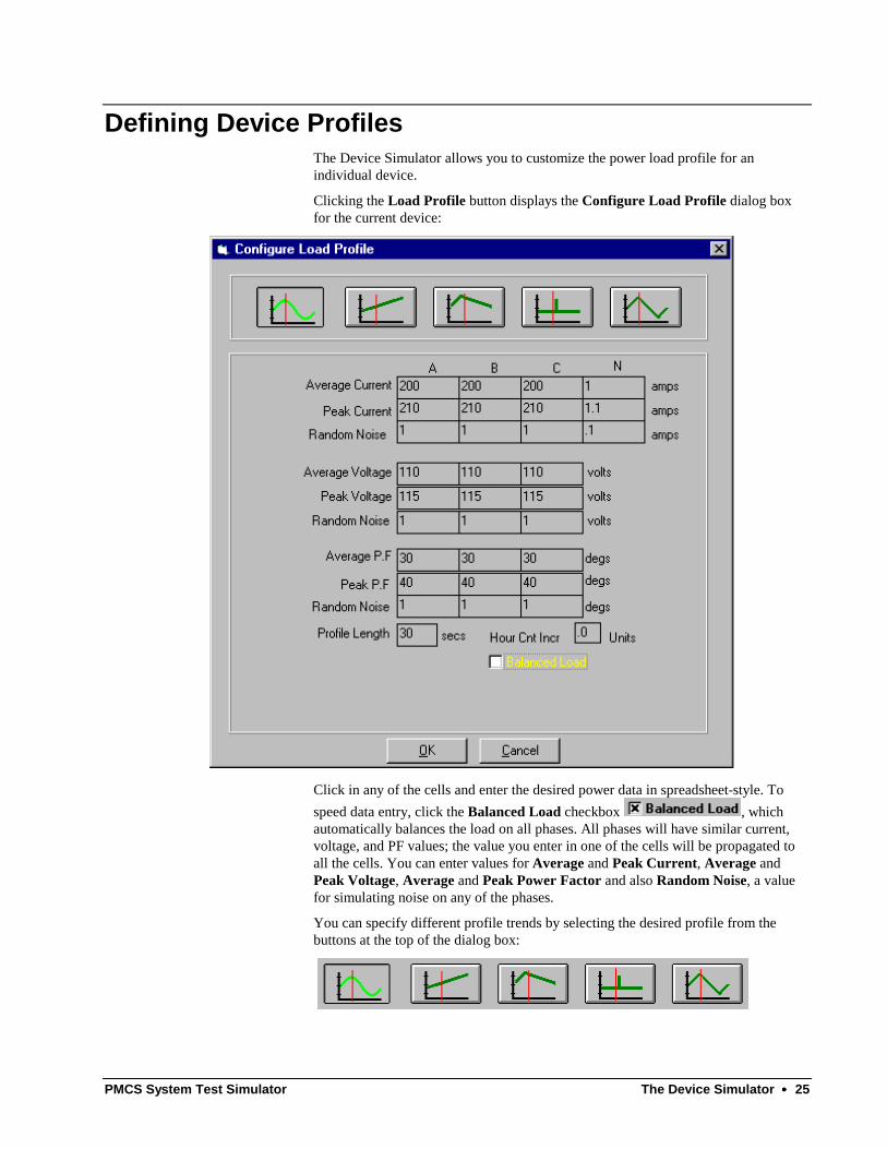
Defining Device ProfilesThe Device Simulator allows you to customize the power load profile for anindividual device.
Clicking the Load Profile button displays the Configure Load Profile dialog boxfor the current device:
Click in any of the cells and enter the desired power data in spreadsheet-style. Tospeed data entry, click the Balanced Load checkbox , whichautomatically balances the load on all phases. All phases will have similar current,voltage, and PF values; the value you enter in one of the cells will be propagated toall the cells. You can enter values for Average and Peak Current, Average andPeak Voltage, Average and Peak Power Factor and also Random Noise, a valuefor simulating noise on any of the phases.
You can specify different profile trends by selecting the desired profile from thebuttons at the top of the dialog box:

26 •••• The Device Simulator PMCS System Test Simulator
Entering the Profile Length sets the time duration that the Simulator will take to runthe selected profile. The profile is cycled continuously.
The Simulator uses a counter to increment energy hours once every second. HourCnt Incr Units allows you to customize the increment for energy hour data – forinstance, energy hours can accumulate by one unit (1, 2, 3, 4, ...) or two units (2, 4, 6,8, ...) every second.
When you have finished configuring the load profile, click OK to save the changesand close the Configure Load Profile window. Cancel closes the window withoutsaving changes.

PMCS System Test Simulator The Device Simulator •••• 27
Defining Events and Special Commands
EventsClicking the Events button opens the Event Generation dialog box. This dialog boxallows you to simulate events for a particular device.
Event codes for some devices may be found in GEH-6508, Modbus Protocol Guide,or in the specific device’s user manual or Modbus protocol guide.
Select a device from the pull-down list in the Event Generation dialog box. Select anEvent Code from the pull-down list or type in the event code number. Event codesare entered as decimal (not hexadecimal) numbers. Refer to the devicedocumentation for lists of available event codes.
Click the Add button to generate the selected event for the selected device. ClickExit to close the Event Generation dialog box.
NOTE: If you select an EPM 3720 from the pull-down list, the dialog box is slightlydifferent, as the 3720 requires that you specify cause and effect keys; refer to theEPM 3720 documentation for Cause and Effect Keys.

28 •••• The Device Simulator PMCS System Test Simulator
Special CommandsThe Spl Command button enables the simulation of various device functions,including trips, sending coil commands, and resetting energy.
Similar to the Event Generation dialog box, the Special Commands dialog boxprompts you to select a Device from the upper pull-down list and a Command fromthe lower pull-down list:
The Device list contains the list of all configured devices (topics) that can executespecial commands. Select a device for which you want to simulate a specialcommand. The Command pull-down list shows the special commands available forthe selected device. Select a command, and click OK to execute it. Click Exit toleave the Special Commands dialog box.
NOTE: Special commands are not supported for most device types.
PMCS System Test Simulator DDE Server Menus & Toolbars •••• 29
DDE Server Menus & Toolbars
In this section, we’ll examine each of the Server’s menus and toolbar buttons indetail, describing its functions and options. We’ll assume that some buttons (such asOK and Cancel) are self-evident and that you can interpret their functions fromgeneral experience with the Windows interface.
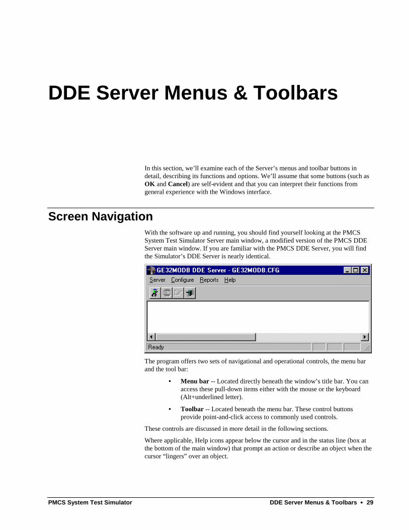
Screen NavigationWith the software up and running, you should find yourself looking at the PMCSSystem Test Simulator Server main window, a modified version of the PMCS DDEServer main window. If you are familiar with the PMCS DDE Server, you will findthe Simulator’s DDE Server is nearly identical.
The program offers two sets of navigational and operational controls, the menu barand the tool bar:
• Menu bar -- Located directly beneath the window’s title bar. You canaccess these pull-down items either with the mouse or the keyboard(Alt+underlined letter).
• Toolbar -- Located beneath the menu bar. These control buttonsprovide point-and-click access to commonly used controls.
These controls are discussed in more detail in the following sections.
Where applicable, Help icons appear below the cursor and in the status line (box atthe bottom of the main window) that prompt an action or describe an object when thecursor “lingers” over an object.

30 •••• DDE Server Menus & Toolbars PMCS System Test Simulator
Menu BarThe PMCS DDE Simulator main window contains four pull-down menus:
• Server
• Configure
• Reports
• Help
…as well as the standard Windows system menu. We’ll take a closer look at thesemenus shortly.
ToolbarThe main window toolbar contains four icons, shown below in Table 1. Click on anicon to perform the action described.
Icon Function DescriptionServer Run Starts the DDE Server
Stop DDE Server Stops DDE Server
Suspend/Resume Suspends or resumes the DDEServer’s activities
Exit DDE Server Exits DDE Server
Table 1. Toolbar icons.
Minimize IconThe following icon appears when the DDE Simulator Server is minimized.

PMCS System Test Simulator DDE Server Menus & Toolbars •••• 31
System MenuThe system pull-down menu is shown below. The menu is standard to Windows;refer to the Windows documentation if you have any questions regarding thesefunctions.
Server MenuThe Server pull-down menu is shown below. Descriptions of the Server optionsfollow.
Switch to Simulator / RunThe first item on the Server menu is either Switch to Simulator or Run, dependingon the current mode.
If the item reads Switch to Simulator, you know that you are currently in Runmode—the DDE Server is able to accept DDE requests from clients and respond tothem.
If the item is Run, the Server program is in Stop mode — no requests are beingaccepted or answered. You must be in Stop mode to make any configuration changessuch as adding new devices or modifying existing devices. To enter Stop mode, closeall DDE client programs to disconnect any active DDE links, then select Stop.
Switch to Simulator jumps from the DDE Server to the Device Simulator.
Run places the DDE Server in Run mode, ready to answer DDE requests fromclients. The Server waits for DDE clients to become active. Once a client is activelymaking requests for data, the PMCS DDE Server retrieves the appropriate data fromthe Device Simulator and answers the requests.

32 •••• DDE Server Menus & Toolbars PMCS System Test Simulator
Note: The Stop command temporarily closes the Device Simulator window, and theRun command will restart the Device Simulator. It may take several seconds for theDevice Simulator to start up after issuing the Run command.
You must configure the Server with at least one device before it can run a simulationor a client requests data from it. Configuration is discussed in Section Two, QuickStart, and also later in this section.
All configuration information is saved to disk and is re-loaded each time the Server isrun.
StopStop sets the PMCS DDE Server off-line, preventing it from requesting any datafrom the Device Simulator. Before you can stop the Server, however, DDE links withclient applications must be broken from any open client applications. This mayrequire closing the client applications.
Once the PMCS DDE Server is off-line, you can make configuration changes.
While the Server is Stopped, a DDE request from a client will automatically returnthe Server to Run mode, unless configuration changes are underway. SelectingConfigure from the Configure menu disables this “auto-wakeup” feature.
Suspend Protocol/Resume ProtocolThis menu item is enabled once the Server starts running. Suspend Protocol andResume Protocol are mutually exclusive options. One or the other will be displayedon the Server menu, depending on the current state of the program.
Suspend Protocol temporarily halts the collection of data by the DDE Serverwithout requiring that the DDE links with clients be broken, whereas Stop requiresthat the links be broken first. When you select Suspend, any DDE links remainintact; they merely become idle until you select Resume.
When you select Suspend Protocol, the Server stops data acquisition and the menuitem changes to Resume Protocol.
When you select Resume Protocol, the suspended DDE links become active again,and the Server resumes answering requests for data.
This is useful if you wish to pause operation of the Server to view data traffic inWWLogger . It has no effect on the Device Simulator; the Simulator continues togenerate appropriate simulated data.
Note that Suspending the DDE Server does not permit you to make any configurationchanges; the Server must be Stopped for configuration changes to be made.
ExitExit is the standard Windows function for leaving the program. A dialog boxprompts you for confirmation that you really want to exit the program. This will alsoexit the Simulator and you will be prompted to save the profile data and registermaps.

PMCS System Test Simulator DDE Server Menus & Toolbars •••• 33
Configure MenuThe Configure pull-down menu is shown below. Descriptions of the Configureoptions follow.
The only option available from the Configure menu is Configure. Selecting thisoption brings up the Configuration dialog box.
PortsThe Simulator supports up to 256 RS-485 ports. We refer to these communicationports as “comm ports” in the documentation. Communication ports must beconfigured before a device can be assigned to that port.
Step 1. Click on the Configure pull-down menu and select Configure.
At the Configuration dialog box click Ports.

34 •••• DDE Server Menus & Toolbars PMCS System Test Simulator
This brings up the Communication Port Configuration dialog box:
Step 2. Select the communication port to configure from the COM Port pull-downlist at the top of the dialog box.
Step 3. Select the appropriate radio button for each of the communication settings:Parity, Stop Bits, Flow Control, and Baud Rate. The default settings are shown.
Typically, only baud rate need be changed to match settings of the devices connectedto the comm port. The other communication settings are fairly standard. Refer to theuser manuals of the individual devices to be sure the communication settings match.
NOTE: Flow Control applies only to systems using an RS-232/RS-485 converter boxother than the recommended converter. Some RS-232/RS-485 boxes requireHardware Flow Control to be enabled; check the product’s documentation to see ifyour RS-485 converter requires this.
Step 4. Click on OK to return to the Configure dialog box.

PMCS System Test Simulator DDE Server Menus & Toolbars •••• 35
Device InfoClick this button to display the Device Configuration dialog box:
AddClick this button to configure a new device. The Add Device Configuration dialogbox appears:
The PMCS DDE Server doesn’t just look at individual devices directly; instead ituses a more flexible virtual addressing scheme, which looks at topics at particularaddresses. A topic consists of a user-specified device name, port number, address,and device type, with information on how often it is to be scanned. While there isusually just a single topic per device, it is possible to have multiple topics obtainingdata from the same device. This feature allows you the ability to scan different datafrom the same device at different intervals.
For example, suppose you want to scan a set of registers at one device every 1000milliseconds, while for other registers a 5,000 millisecond scan is adequate. In this

36 •••• DDE Server Menus & Toolbars PMCS System Test Simulator
case, you could set up two separate topics, each addressed to the same device, but setto scan at different scan intervals.
Enter a name for the device. This will be the topic name referenced from clientapplications. This name must be unique, must begin with an alphabetic character, beno more than 20 characters long (8 characters if used with a third-party HMI client).Only alphanumeric characters and underscores are permitted; the topic name cannotinclude spaces or special characters, such as: + * / /, ? () “ ‘.
Select the Device Type from this pull-down list.
Enter the Slave address assigned to the device in this field. On a single RS485network, all addresses must be unique, though it is acceptable to have devices withthe same address if they are on different RS485 networks. For example, Network 1,Device 1 is recognized as different from Network 2, Device 1. For purposes of theDDE Simulator, if you configure multiple devices with the same Modbus address, theSimulator automatically differentiates between them as though they were on separateRS485 networks.
The device addresses must fall into the following ranges:
• Modbus devices other than the Modbus Concentrator may haveaddresses in the range 1–247.
• POWER LEADER Modbus Concentrators must have addresses in therange 1–32.
• Commnet devices must have addresses in the range 33–247.
For details on addressing requirements, refer to GEH-6502, PMCS NetworkArchitecture Guide.
Enter the scan interval to be assigned to the device (the default is 1000). The scaninterval is the target time in milliseconds at which the current device will be scanned;it is the scan time that could be achieved under optimal circumstances. This will varygreatly from network to network, depending upon the number and type of devicesbeing managed, the amount of data being requested by the client applications, andeven the architecture of the network itself. The valid range for scan interval is 1 to9999999; scan intervals less than 100 milliseconds are usually impossible due tonetwork timing constraints.
Clicking OK accepts the entries and returns to the Device Configuration dialog box.
ModifySelect the device (topic) to be modified and click the Modify button. The ModifyDevice Configuration dialog box appears. The options and fields in the ModifyDevice Configuration dialog box are similar to those in the Add Device

PMCS System Test Simulator DDE Server Menus & Toolbars •••• 37
Configuration dialog box. Make any necessary modifications and click on the OKbutton. The modified information is reflected in the Device Configuration dialogbox.
DeleteTo delete a device (topic), select it and click on this button.
Activate checkboxAt the bottom right of the Device Configuration dialog box, you’ll notice a checkbox labeled Activate. This box provides a one-step way to turn a device on or off atthe Server. Make sure this box is checked for each device; devices that are notactivated will not communicate with the Server and will not be available to DDEclients. Conversely, for troubleshooting purposes, you can use this checkbox toquickly take a device off-line.
Device Type InformationCAUTION: Advanced users only.
Do not access this option unless you have studied the Advanced Topics section of theUser’s Guide and are sure of what you are doing. Misuse of this option may causeerrors or malfunction of the Server.
See Section 6 of the User’s Guide, Advanced Topics, for information on this option.
Operational ParametersCAUTION: Advanced users only.
Do not access this option unless you have studied the Advanced Topics section of theUser’s Guide and are sure of what you are doing. Misuse of this option may causeerrors or malfunction of the Server.
See Section 6 of the User’s Guide, Advanced Topics, for information on this option.

38 •••• DDE Server Menus & Toolbars PMCS System Test Simulator
Reports MenuThe Reports pull-down menu is shown below. Descriptions of the reports optionsfollow. The System Test Simulator generates two kinds of reports and saves them as.txt files on disk for viewing and printing. The Reports menu is always available; theServer need not be stopped to run a report.
ConfigurationSelecting this option generates a report on the current configuration of the Server.The report is saved as a text file containing the following information: configureddevice types (with the mnemonic list, function codes added, and register groups),configured comm ports (with port parameters), and configured devices (withDevTpName, ComPortName, SlaveAddr and ScanInterval). (Note that the Simulatorassigns a com port number to each device, but that this is meaningless with regard toSimulator performance.)
A dialog box prompts you for a file name and location to save the file. The defaultfile name is config.txt.
Active LinksThe Active Links option (available only when in Run mode) creates a text filecontaining the following information: currently active comm ports and active devices(along with their device type, register groups, and mnemonic items). You will beprompted for a file name (default file name is active.txt). The information in this textfile can be useful for debugging communications problems.

PMCS System Test Simulator DDE Server Menus & Toolbars •••• 39
Help MenuThe Help pull-down menu is shown below. The options are all standard Windowsfunctions.
ContentsBrings up a listing of all the topics for which help is available. The interface isstandard Windows and is easy to use. If you are not sure how to navigate the Helpwindows, refer to your Windows manuals.
About ServerPresents the program version and copyright information.
ToolbarThe Simulator DDE Server’s main window toolbar contains four buttons, shownbelow in Table 2. Click a button to perform the action described.
Icon Function DescriptionServer Run Starts the DDE Server.
Stop DDE Server Stops DDE Server.
or
Suspend/Resume Suspends or resumes the DDE Server’sactivities. When in Suspend mode, thisbutton Resumes the Server’s operation.When the Server is running, this buttonSuspends the Server.
Exit DDE Server Exits DDE Server.
Table 2. Toolbar icons appearing on the Server main window.

40 •••• DDE Server Menus & Toolbars PMCS System Test Simulator
(This page left blank intentionally.)

PMCS System Test Simulator Troubleshooting •••• 41
Troubleshooting
Trouble-shooting the PMCS System Test SimulatorThis section describes some simple steps that can be taken to isolate and correctcommunication problems. The problems described here represent the most probablecauses of communication failure.
NOTE: This is a general trouble-shooting guide–it is not intended to cover everypossible problem. If you still cannot establish communications after reading thissection, call the GE Resolution Center, at 1-888-GE-RESOLV.
WWLoggerWWLogger is a software application that is included with the PMCS installation. Itis found in the GE_PMCS/TOOLS directory, and can be used for diagnosticspurposes. The WWLogger application tracks all error messages generated by DDEcommunications or Server to device communications. Obviously this can be oftremendous value for trouble-shooting purposes. The messages tracked byWWLogger describe the application and topic or device that caused a given error.This information can then be used to diagnose and correct the cause of the error.
If you are experiencing trouble, launch WWLogger, and attempt to reproduce theerror condition. You can then use the error messages displayed by WWLogger totroubleshoot your problem.
Error messages that may be encountered in the WWLogger are listed at the end ofthis chapter, in the section titled Error Messages.
Communications – Client to ServerThis section explains the most common error situations that can occur whenattempting to establish a DDE conversation between client applications and the DDEServer.
When a client requires the status of a DDE item, it opens a link with the DDE Serverand requests the data. The DDE Server retrieves simulated device data from theSimulator and sends it to the client application.

42 •••• Troubleshooting PMCS System Test Simulator
The DDE Server also begins monitoring the data and advises the client whenever aparameter changes. The client application simply tells the DDE Server what register,coil number, or I/O point to read or write. The DDE Server then automaticallyupdates the client upon any change of that parameter.
Always start the DDE Server before starting any client software. If a client attemptsto establish a link with a Server that is not running, an error message will result.
When an error message is displayed, note the information shown. You can oftendetermine the source of the error message from the message itself – usually anapplication that is not running or a topic that is not properly configured.
Below are several situations that will cause a DDE conversation error message toappear:
1. The DDE Server application is not running. You can verify this byopening the Windows Task List (press Shift+Ctrl+Esc keys) andchecking the list of currently running applications for the Server.
2. The Server program name is misspelled in the DDE Access Namedefinition. The Server is running, but its name is misspelled in one ormore DDE Access Name definitions. The name entered in the DDEAccess Name definition must be the DDE Server’s actual programname (less the .exe extension) as seen in the Windows File Manager. Ifthe name is misspelled, the Server can not be found.
3. The topic is not defined in the Server or it is misspelled. The Servermay be functioning properly, but if a client requests data from a topicthat doesn’t exist, an error is generated.
4. The mnemonic or register address is not defined in the Server or itis misspelled. The Server may be functioning properly, but if a clientrequests data from a mnemonic or register address that doesn’t exist, anerror is generated.
Let’s assume that the Server’s name is spelled correctly in the client’s DDE requestand that the Server is running. The client is now looking for a topic defined in theServer; for example, Device1. To check the topic name, close the client (the Servercannot be configured if the client is running) and open the Server’s program window.Invoke the Configure:Device Info... command. Is there a configured device listed asDevice1 in the dialog box? Is it spelled exactly the same (including spaces, etc.) as itis in the DDE Access Name definition?
NOTE: Make sure there are no blank spaces after the topic name in both the Serveror in the DDE Access Name definition in the client.
If nothing appears in the Server’s window, try using WWLogger to track your errormessages. The most probable error message indicates that the item used with one ormore tagnames is unrecognized by the Server. Tagnames use specific namingconventions when accessing data from a Server, and deviation from theseconventions can cause errors.

PMCS System Test Simulator Troubleshooting •••• 43
NetDDE TroubleshootingIf you are using NetDDE to share a Server’s data with clients across a network, makesure a share called GE32MODB|* exists in the system and has been trusted withproper parameters. A share need to be created only once, but each NT user shouldtrust the share explicitly.
Refer to the NetDDE documentation for further information on how to set up sharesand trusting a share. Information may also be found in the Microsoft Knowledgebaseby searching for keyword “NetDDE”.
NOTE: Make sure you’re using the version of NetDDE supplied with MicrosoftWindows NT 4.0 Workstation. Other versions of NetDDE are not supported by thePMCS DDE Server.
Trouble-Shooting ChartThe following table lists a variety of common problems, possible causes, andrecommended solutions.
Error Condition Possible Cause SolutionClient application times outwhile setting up DDE link orreceives negativeacknowledgment.
Valid Data Timeout isset too low.
Increase the Valid Data Timeout value; itshould be around 5000 milliseconds (5 sec) formost networks.
#NAME on Excel spreadsheet(client application)
Item name is incorrect. Check for precise spelling and correctmnemonic name. Make sure the device is notdeactivated.
#N/A on Excel spreadsheet(client application)
Data is currentlyunavailable.
Server may be down, suspended, or stopped, orport may be suspended.Data request may not yet have been processed.
The Simulator or Server areshowing an incorrect deviceconfiguration.
The Simulator may beusing a different set ofconfiguration files.
Check the GE32MODB.ini file to ensure thatthe Simulator is referring to the correctconfiguration files.
Starting the Event Server forcesthe GE32MODB Modbus DDEServer to start up, and closingGE32MODB forces the EventServer to shut down. Cannotrun GE32MODB and theSimulator at the same time.
Your systemcomponents areconfigured as NTServices.Preconfigured Servicedependencies arecausing this behavior.
Shut down the PMCS NT Services. Start theDDE Simulator. Restart the PMCS NTServices. GE32MODB will not start if theDDE Simulator is already running. Be sure toshut down and restart the PMCS NT Servicesafter you finish with the Simulator to restorenormal operatoin.
44 •••• Troubleshooting PMCS System Test Simulator
Error MessagesThis section provides descriptions of the error messages which may be generated bythe PMCS DDE Server. These messages are logged in the WWLogger
Activation of <item name> item failed, item not found in register’s item list.
Activation of an item failed when the client requested a link to this item. Pleasecontact Customer Service. This error message does not appear in normalcircumstances — it appears only if the item list is corrupt or if the toolkit gives anout-of-sequence ProtActivateItem() call.
Could not open RMS data file <file name>
The data file to store MicroVersaTrip device Peak Demand computation parameterscould not be opened by the Server as defined in GE32MODB.INI. The .ini file entrymay be wrong or the file may have been deleted.
CServerApp::OnDeleteDev - Invalid toolkit index
Internal error in the Server. Please contact Customer Service.
DDE Execute <DDE execute command> failed
Possible causes are:
a) The execute command is misspelled.
b) Parameters passed with the execute command are not proper. Refer tothe Server interface specifications for correct parameter syntax andrange.
c) The execute command string has some extra space characters. TheServer does not accept extra space characters in execute commands.Please follow the Server interface specifications strictly.
d) The DDE execute command is not supported for the topic on which itwas issued.
<device name> device got deleted – discarding packet
This is an informational message. A client application deleted a topic and the Serveris deleting a scheduled communication packet.
Error allocating new topic (<topic>, <toolkit id>) => 0
The Server is unable to initiate a DDE transaction with the topic. The possible causesare :
a) The topic is not configured on the Server. Configure the topic in theServer.
b) The communication port associated with the topic could not be openedor initialized properly. In this case, the Server displays communicationport-related error messages immediately preceding this error message inWWLogger.
c) The device type of the topic is not configured. Configure the topic’sGeneric Device Type in the Server.
Failed to activate item(<logical device handle>, <Protocol Handle>)=>0
Server internal error. Please contact Customer Support.

PMCS System Test Simulator Troubleshooting •••• 45
Failed to create item (<logical device handle>) (<toolkit handle>) (<item name>)=> 0
Possible causes are :
a) The item name is not spelled correctly on the client.
b) The item register(s) is (are) not configured in any of the register groupsof the device type. Check the device type’s register-groupconfiguration.
c) If the item name uses a mnemonic convention, then the mnemonic is notdefined on the Server. Check the device type’s mnemonicconfiguration.
Failed to deactivate item(<logical device handle>, <Protocol Handle>)
Server internal error. Please contact Customer Support.
Failed to delete item(<logical device handle>, <Protocol Handle>)
Server internal error. Please contact Customer Support.
No Write to Individual Discrete Bits
The client tried writing to individual bits of a read/write register, which is notallowed.
RegFormat Name is INVALID
The register name (either as mnemonic equivalent or as item name) is not valid.
The device type <device type name> is NOT a valid type for topic
The Server detected an unconfigured device type for a topic being created. Possiblereasons are :
a) The <device type name> has been deleted from the device-typeconfiguration file (GE32MODB.CFG). Reconfigure the device type thatgenerated the error or, if you intend to remove all the devices of thatparticular type, go to device(topic) configuration and remove all thetopics with this device type. NOTE: This applies to generic devicesonly.
b) GE32MODB.INI entry DocFile points to an incorrect device-typeconfiguration file. Enter the correct path to the configuration file.
Unable to free topic (hLogDev = <logical device handle>)
Internal error for the Server. Please contact Customer Support.
Unable to open RMS data file for rewriting RMS data
The RMS data file has been deleted since the Server started. Restart the Server. TheServer will create a new RMS data file during startup.

46 •••• Troubleshooting PMCS System Test Simulator
(This page left blank intentionally.)

PMCS System Test Simulator Advanced Topics •••• 47
Advanced Topics
IntroductionCAUTION: For advanced users only!
These advanced options are for experts only! Do not attempt these actions if you arenot sure of what you are doing; it is possible to render your PMCS DDE Serverinoperable, forcing you to reinstall it and potentially lose your device configurations.Please read all instructions before attempting any advanced configuration.
The information contained in this section applies to two types of devices:
• the broadly-defined generic devices that must be completely defined bythe user
• the highly flexible GE Fanuc PLC family of products.
The GE Fanuc PLC 90/70, PLC 90/30, and Micro90 PLC consist of a backplane towhich may be attached a wide variety of modules with a broad range of functions,from metering and data collection to process control. Because these devices are soflexible and there is no way to predict the options that will be chosen by the end user,they must be configured in the same manner as a generic device.
Device Type Information –Adding Generic Devices
The PMCS DDE Server is preconfigured to support the POWER LEADER family ofpower-management devices, as well as a variety of third-party devices. However, youmay add additional kinds of devices by creating your own device type. These“generic” devices have the register maps and functions that you assign, as explainedin this section. The generic device type does not support the use of the DDE Server’sspecial device handling, such as automatic time synchronization, waveformcapability, or event handling.
The procedure for adding a generic device is as follows. The details of each optionmentioned are provided after the procedure. Remember that the Server must bestopped before you can do any configuration.

48 •••• Advanced Topics PMCS System Test Simulator
Step 1. Select the Device Type Info option from the Configuration menu to displaythe Device Types dialog box, shown below.
Step 2. Enter the name for your new generic device in the field at the bottom of thedialog box. The field is labeled Enter Device Type Name. Click the Add DefaultType button to add the new device type to the list of Configured Device Types.
Step 3. Next, select the generic device from the Configured Device Types list, andclick the Function Codes button to add the functions codes supported by this devicetype. Setting up the register groups for a device type is mandatory; you may alsoenter an optional mnemonic list. To do this, you’ll need to have on hand a completeprotocol reference for the device before proceeding.
Add Default Type
Entering the name of a new device type in the Enter Device Type Name box enablesthe Add Default Type button. Names may be up to 20 alphanumeric characters longand cannot include embedded spaces or special characters, such as + * / /, ? () “ ‘.
Click on this button to add your new device type. You will need to do furtherconfiguration after creating a new device type. See the Register Map section fordetails on defining the device type’s register map.

PMCS System Test Simulator Advanced Topics •••• 49
DeleteThe standard device types may not be deleted, so this button is grayed when astandard device type is selected. Only generic (user-defined) device types may bedeleted. Select a user-defined device type and click Delete to delete that device type.
Function Codes
Click on this button to attach or detach function codes to a device type. You willneed the device’s Modbus RTU protocol specification to know the correct codes toadd for the new device type.
Clicking this button displays the Modbus Function Codes dialog box:
The two list boxes, Available Function Codes and Selected Function Codes, aremultiple-selection list boxes. The Available Function Codes box lists the functioncodes available to any generic device type; the Selected Function Codes box liststhose function codes that are to be assigned to a specific device type. Place thedesired function codes into the Selected Function Codes box using the Add andDelete buttons, then click OK.
Select the function codes to be added from the Available Function Codes list boxand click this button. The selected function codes are added for the device type anddisplayed in the Selected Function Codes list box.
This button is displayed only when there are no user-configured register groups forthe device type. To remove a function code support from the device type, all theregister groups that are added are removed. (To delete a register group from the

50 •••• Advanced Topics PMCS System Test Simulator
device type, refer to Delete under the Register Map subsection.) Select the functioncodes to be deleted from the Selected Function Codes list box and click this button.The selected function codes are deleted for the device type and displayed in theAvailable Function Codes list box.
NOTE: You cannot delete function codes if any user-configured register group existsfor this device type. To delete function codes, you must first delete all the registergroups calling those functions.
Register Map
Click this button to add, delete, or modify register groups for the selected devicetype.
NOTE: Register Maps for preconfigured devices may not be modified or deleted.When a preconfigured device type is selected, you will find that buttons for changingregister maps, function codes, and mnemonics are disabled. Only generic devices andPLC type-devices are intended to have any modifications to their Register Groups.
When this button is clicked, the Register Map dialog box appears:
The Add New Register Group..., Delete..., Modify..., and Change Register Namebuttons are described below.
Adding a Register Group
Click this button to add a new register group. The Select Register Group Typedialog box appears:

PMCS System Test Simulator Advanced Topics •••• 51
Enter the Register Group name. The name may be up to 20 alphanumeric charactersand cannot include embedded spaces or special characters, such as: + * / /, ? () “ ‘.
Select the register type from the Select Register Type pull-down list. The ModbusRegister Types shown are determined by the function codes selected previously. Thefour types of register groups that support the Modbus function codes are R0, R1, R3,R4. The table below describes the types, registers, supported codes, and uses.
TypeCode
Type ofRegister
SupportedFunctionCodes Use
R0 Coils 01 Reading coil statusR0 Coils 05 Setting/forcing/executing coilsR0 Coils 15 Setting/forcing multiple coils
R1 Contacts ordiscrete inputs
02 Reading contact/discrete inputs
R3 Actual value orinput register
04 Reading actual value or inputregisters
R4 Setpoint orholding register
03 Reading setpoint or holdingregisters
R4 Setpoint orholding register
06 Presetting single setpoint register
R4 Setpoint orholding register
16 Presetting multiple registers
You will need the device’s Modbus RTU protocol specification for the correct codesto add or delete.
Click OK to accept your new register group; the Register Group dialog box isdisplayed for you to finish defining the characteristics of the new register group.

52 •••• Advanced Topics PMCS System Test Simulator
The PMCS DDE Server supports both decimal and hexadecimal address formats.Select the type of addressing you wish to use (refer to the device user manual if youare unsure) by clicking either the Decimal or Hexadecimal radio button. Next, enterthe Start Address and End Address for the register group in the appropriate boxes.The PMCS DDE Server supports Modbus RTU extended addressing; in decimalmode, the range is 0 to 65535; in hexadecimal mode, the address range is 0 to FFFF.Refer to Appendix A – Register Addressing Conventions for more information onformatting register addresses.
Next, set the desired polling speed by clicking one of the radio buttons - Fast Poll,Slow Poll, or Poll Once.
The polling speed is based on the scan interval for the topic. A polling speed of Fastattempts to scan at the assigned Scan Interval. This is the default. Setting the pollingspeed to Slow causes this register group to be read once every ten scan intervals. Thisis typically used for setpoints or low-priority parameters that change infrequently.Slow Poll is a multiple of Fast Poll, with a default value of 10. This multiple iscontrolled by a setting in the PMCS DDE Server’s .ini file, and may be changed ifdesired. See the section PMCS DDE Server .ini File.
For example, if the scan interval is set to 1000 msec (1 second – this is the defaultvalue), setting the Poll Speed to Fast Poll causes the Server to scan as close to every1000 msec as possible (based on the network load, communication bandwidthavailability, etc.); setting the Poll Speed to Slow Poll reduces the scan attempts toonce every 10,000 msec (10 seconds), or as close to this as possible; i.e.; not lessthan 10 seconds (≥ 10,000 msec.)
Poll Once means that this register group is scanned only the first time data isrequested by a client application. All future requests for the same data receive thedata from this poll. If the device is later declared to be dead, the device is scannedperiodically until it comes back on-line, at which point the Poll Once data are reread.

PMCS System Test Simulator Advanced Topics •••• 53
This is useful for registers with settings of a more permanent nature, which need to beread but are unlikely to change.
Invalid Register BlocksA register block consists of a contiguous piece of a device’s memory that containsmultiple pieces of data. Within this block, however, some addresses may be unusedby the device. We can make the PMCS DDE Server aware of these unused orextraneous addresses by specifying them as invalid register blocks. (The Server’sregister maps for supported devices have already been optimized; only genericdevices’ invalid register blocks must be entered manually.)
An invalid register block is a list of registers within a register group that should notbe polled for data by the Server, perhaps because they are unused by the device itselfor simply because they are not desired.
Invalid register blocks allow the Server to focus its attention on only those registersof interest; by not asking the Server to poll addresses that contain no data of interest,we can improve the Server’s potential performance. Also, some devices, if asked fora valid register block that happens to contain invalid registers within it, will return amessage that the entire block is invalid. Thus, it can be important to identify anyinvalid blocks to the Server.
AddClick this button to access the Add Invalid Register Range dialog box.

54 •••• Advanced Topics PMCS System Test Simulator
Enter the start and end addresses for the invalid block, following the addressingconventions.
Modifying an Invalid Register BlockTo modify an invalid register block, select the block from the Invalid Registers listbox and click the Modify button. The Modify Invalid Register Range dialog boxappears. Follow the method used for adding invalid register blocks to make changesto the register block.
Deleting an Invalid Register BlockClicking the Delete button deletes the selected invalid register block.
Deleting a Register GroupClicking the Delete button deletes the selected register group.
Modifying a Register GroupClick the Modify button to modify the register group. The Register Group dialogbox appears. Make any necessary changes to the register group Start Address, EndAddress, Poll Speed, and Invalid Register blocks, then click on the OK button.
Changing a Register Group Name
Click on this button to change the name of the selected register group. The ChangeRegister Group Name dialog box appears:
Enter the new name in the Register Group field, then click OK to accept or Cancelto back out of this dialog box.
Mnemonics
Mnemonics are an optional way of naming registers or groups of registers, byassigning an easily remembered name to a register address. From the Device Typesdialog box, click this button to add, delete, or modify mnemonics. Mnemonics areuseful to speed selection of registers – it’s much easier to remember Trip_Set_Pointsthan R41234A5.

PMCS System Test Simulator Advanced Topics •••• 55
When this button is clicked, the Mnemonics dialog box appears:
Adding a MnemonicClick the Add button to add a mnemonic. The Add/Modify Mnemonics dialog boxappears:
Enter the Mnemonic Name. You may use up to 20 alphanumeric characters, but noembedded spaces or special characters, such as + * / /, ? () “ ‘.
Enter the register address in this field. Follow the register-naming conventionspresented in Appendix A.
Click OK to accept your changes.
Modifying a MnemonicClick on the Modify button to modify the selected mnemonic. The Add/ModifyMnemonics dialog box appears. The procedure is similar to adding a mnemonic.Make any necessary modifications to the mnemonic name or register address, thenclick OK.
Deleting a MnemonicSelect a mnemonic from the Item Mnemonic Map list box and click the Deletebutton to remove it from the list.

56 •••• Advanced Topics PMCS System Test Simulator
Optimizing Server PerformanceEvery network has different devices, different numbers of RS485 ports to support, adifferent number of devices, and various client software requesting different amountsof data. System administrators with Modbus RTU network experience may be able toanalyze their particular network’s needs and adjust some of the PMCS DDE Server’sadvanced settings to improve its performance. These settings are discussed below.
With regard to the System Test Simulator and the server Operational Parameters, it isrecommended that you not change any of these settings. There is little reason to alterthese parameters, since they concern communications between the DDE Server andthe devices in a real network. In the Simulator, the peculiarities and nuances ofnetwork communications have been replaced by the software of the DeviceSimulator. They are explained here to help you better understand PMCS.
Operational ParametersClicking on this button in the Configuration dialog box causes the ServerOperational Parameters dialog box to appear:
Protocol Timer TickThe Protocol Timer Tick is the time interval (in milliseconds) at which protocol isexecuted; the frequency at which the Server checks for work to do. A good analogymight be that the protocol timer tick serves as a metronome or heartbeat to theServer. Every tick, the Server executes a function, whether it is to listen at aparticular port or to send a message to a device. The default is 65 milliseconds. Atvalues below this level, the Server may query devices too quickly for the devices toconsistently answer correctly.
When the Protocol Timer Tick field has been changed, the OK button is enabled. Itis disabled until any changes are made. Click on this button to accept changes. Thechanges take effect the next time the Server software is launched (not to be confusedwith Run from the Server menu).
CAUTION: Changing the Server operational parameters can adversely affect theServer’s performance. If you are unsure of how to adjust any of these settings,consult Customer Support before making any changes.

PMCS System Test Simulator Advanced Topics •••• 57
PMCS DDE Server .ini FileThe application program’s .ini file contains several lines that may be modified byknowledgeable and qualified personnel to fine-tune performance of an individualnetwork. Do not modify these items unless you are experienced with the PMCS DDEServer.
NOTE: Both the real PMCS Modbus DDE Server program and the Simulator DDEServer program use the same .ini file, which points to configuration files for bothapplications. Be careful when making changes to the .ini file; be sure that you aremaking changes to the Simulator section of the file only.
This section of theGE32MODB.ini file applies tothe Simulator. Any changesto the Simulator’s settingsmust be made here. Be surenot to change any other partof the .ini file unless youintend those changes toapply to the real PMCS DDEServer application.
As explained above, these settings should not usually be modified for purposes of theSystem Test Simulator. They are useful primarily for real PMCS networks.
CAUTION: Back up the application’s current .ini file before attempting anymodifications.
Open the application’s .ini file with Windows Notepad. This file is namedGE32MODB.ini and is located in the Windows NT directory. The parameters aregrouped by subject:
[Server Operational Parameters],[GE32MODB], etc.
Look for the GE32SIM group. These are the settings that apply specifically to thePMCS System Test Simulator.

58 •••• Advanced Topics PMCS System Test Simulator
Slow Poll CountThe slow poll count is not used by the Simulator. Do not change this parameter.
NOTE: Do not change any other parameters of the .ini file, as doing so mayadversely affect Server performance.

PMCS System Test Simulator Appendix A - Register Addressing Conventions •••• 59
Appendix A - RegisterAddressing Conventions
Data-Addressing ConventionsThe PMCS DDE Server is capable of interpreting both decimal and hexadecimaladdresses. This allows access to the Modbus RTU protocol’s extended register mode.The two addressing schemes are identical with one exception; in hexadecimal mode,an “X” is inserted prior to the address number to indicate that the address followingis in hexadecimal format. The R character is ALWAYS present. Items in < >represent a variable numeric value. Capital letters in brackets [ ] indicate a hardcharacter that does not change; it is either present or not. Lower-case letters inbrackets [ ] indicate switches that may or may not be present; refer to the followingsections for details.
The basic addressing scheme is as follows:
R indicates a Registeraddress follows.
f indicates theregister type.
X indicates a address ishexadecimal. If the X is notpresent, the address is readas decimal.
nnnn is the actual address.Four characters are required,so leading zeroes must beused if necessary. Forexample, the correct syntax is0025 rather than 25.
R <f> <[X] nnnn>
Switches may be used to modify addresses. The possible switches are shown below,and are detailed in the following sections:

60 •••• Appendix A - Register Addressing Conventions PMCS System Test Simulator
t represents the type of data, if there areany special conventions. See the
following section “Special NamingConventions” for details.
A indicates that the data is an Array.See the following section “Register
Array Format” for details..
-b represents the reading ofindividual bits. Not present ifreading whole registers or anarray of registers. See thefollowing section “IndividualBits in Registers” for details.
lll provides the length of the arrayor ASCII string in bytes, This fieldis present only if the addressrepresents an array or an ASCIIstring. Leading zeros are notrequired for this field.
R <f> <[X]nnnn> [t] [A] [lll] [-b]
Standard Data OrganizationData is organized according to data type, numeric range, tag type, and access type.
Data TypesThere are four data types typically used by the GE devices. These four data types arethe possible values for ‘f’ in the address. (Each data type is organized in a separatetable for each device in this manual):
1. Dynamic Value
2. Setpoint
3. Command Coil
4. Fixed Value
Each data type is assigned a range of register numbers, tag type, and access as shownbelow:
Data Organization
DataType
Use RegisterRange(hex)
RegisterRange(decimal)
DDETagType
Type ofAccess
CommandCoil
1. Commands a device to takeaction.2. Reads the status of an actionor discrete input.
R0X0000 –R0XFFFF
R00000 –R09999
Discrete Read andWrite
DynamicValue
Read frequently, such asmetering values which changeconstantly
R3X0000 –R3XFFFF
R30000 –R39999
Analog ReadOnly
FixedValue
Read only once at power-up.Info such as Product ID andconfiguration options
R4X0000 –R4XFFFF
R40000 –R49999
Analog ReadOnly
Setpoint Read infrequently R4X0000 –R4XFFFF
R40000 –R49999
Analog ReadOnly

PMCS System Test Simulator Appendix A - Register Addressing Conventions •••• 61
ExamplesHere are some examples of different types of register numbers:
Registernumber
Represents
R00005 Coil command, number 5, with Read/Write access to the user
R31005 Dynamic value, number 1005, Read Only access
R43010 Fixed value or Setpoint, number 3010, with Read/Write access tothe user
Special Naming ConventionsSpecial handling of data from devices can be done by using the followingconventions:
Long Words and Special NumbersBy default, a register item is treated as an unsigned integer. To treat the contents ofany register differently, refer to the table below:
Special Data Item Naming Convention ExampleUnsigned 16-bit Integer Default R40001
16-bit Signed Integers with valuesbetween -32,768 and 32,767
Append letter I to item number. R40001I
32-bit Signed Integers(Long Integers)
Append L to item number. R40001L
32-bit floating point numbers Append F to item number. R40001F
Modulus 10000Used in 32-bit register mode forEPM 3710 and 3720.
Append E to the item nameNOTE: See 3710 and 3720 ACM Modbus Protocol Manuals fordetails.
R40010E
ASCII data string Append S to item number.[lll] field immediately after S character represents the number ofcharacters to read. If no length is specified ([lll] field is notprovided), only one register of characters (2 or 4) will be read. TheHigh byte represents the first character, and the Low byte representsthe second character.NOTE: No array type is allowed with S data items, nor are ASCIIstrings supported for coil registers.NOTE 2: For most devices (16-bit mode), there are 2 characters perregister. For 32-bit mode devices, there are 4 characters perregister.NOTE 3: The maximum value for the S string is 250.
R40010S020

62 •••• Appendix A - Register Addressing Conventions PMCS System Test Simulator
Individual Bits In RegistersIndividual bits in registers are read-only. They can be read as discrete/integer tags byusing the following notation (explained beneath):
R indicates a Registeraddress follows.
f indicates theregister type.
X indicates an address ishexadecimal. If the X is not present,
the address is read as decimal.
nnnn is the actual address. Fourcharacters are required, so leadingzeroes must be used if necessary.For example, the correct syntax is0025 rather than 25.
D stands for Discrete typespecifier, and indicates that bit
data is being requested.
L indicates the specificnumber of bits beingrequested.
B indicates thestarting bitnumber.
R <f> <[X]nnnn>DL-B
Examples
RegisterNumber
Represents
R40001D1-0 Specifies least significant bit of first holding register
R30008D1-15 Specifies most significant bit of an input register
R40001D2-5 Specifies 6th and 7th from the least significant bit of first holdingregister.
Register Array FormatIf multiple data items are being requested from a single topic, it is more efficient torequest a block of contiguous registers than to place multiple requests for singleregisters. This is referred to as register array format. The register array format isused for the following applications:
• to read a block of register values into a column of cells in a worksheet(Excel or Access).
• to pass waveform data to a client application (refer to GEH-6509,PMCS DDE Server Interface Reference, for details)
The rules for register arrays are as follows:
1. A register array, or series of consecutive registers, can be treated as ablock of numeric values. Up to 100 sixteen-bit registers or 50 thirty-two-bit registers can be read as a block. Enter the starting registeraddress, and append it with type specifier “A”, followed by the lengthfield. For example, the register address R30501A12 accesses registers501 through 512 as a block.

PMCS System Test Simulator Appendix A - Register Addressing Conventions •••• 63
2. When the DDE Server returns a new value for a register array to theclient, it is in the form of a character string containing a value for eachregister, separated by a carriage return and line feed.
For example, for R30021A6, the values returned might look like this:
50<cr><lf>
17<cr><lf>
0<cr><lf>
5<cr><lf>
1007<cr><lf>
20<cr><lf>
NOTE: All arrays must be terminated by a null character (ASCII 0).
3. When the client application writes a value to a register array, it must bein the form of a character string containing a value for each register inthe array. The register values can be separated by commas, tabs, spaces,carriage returns or line feeds. For example, for R40001A6, the valuestring could be written:
1,2,3,4,5,6
or
1<tab>2<tab>3<tab>4<tab>5<tab>6
or
1 2 3 4 5 6

64 •••• Appendix A - Register Addressing Conventions PMCS System Test Simulator
(This page left blank intentionally.)

PMCS System Test Simulator Index •••• 65
Index
AAbout Server 39
Cclient 2client-server 2Configure menu 33
DDDE 2DDE Server 3DDE Simulator icon 9
HHelp menu 39
IInstalling PMCS DDE Simulator 7
MMain window controls 29menu bar 29Minimize icon 30
PPMCS DDE Server 3Power Management Control System (PMCS) 3
RReports menu 38
Sserver 2Server menu 31System menu 31System Test Simulator
main window 29
TToolbar 29, 30, 39Toolbar icons 30, 39topic 35
WWWLogger 32, 41, 44

g GE Consumer & Industrial General Electric Company 215 Anderson Avenue, Markham ON, L6E 1B3, CANADA USA & Canada: 1-800-547-8629 Global: (905) 294-6222 Fax: (905) 201-2098 Email: [email protected] <mailto:[email protected]>
GEH-6515 R045 01/02 © 2000 - 2004 General Electric Company