plw 300 & lw 4/600 ps - tim.id.autim.id.au/laptops//apple/misc/plw_300.320_lw_4.600_ps.pdf ·...
TRANSCRIPT
Service Source
K
PLW 300 & LW 4/600 PS
Personal LaserWriter 300, Personal LaserWriter 320,LaserWriter 4/600 PS
Service Source
K
Basics
PLW 300 & LW 4/600 PS

Basics Paper Paths - 1
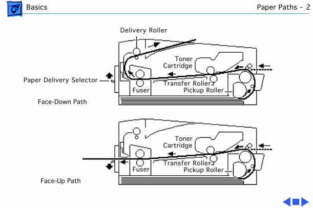
Paper Paths
There are two paper paths in this family of printers. Paper is fed from the paper cassette or manual-feed slot and delivered to the face-down tray or the face-up delivery slot.
When the paper delivery selector is in the up position, paper is delivered face-down. When the selector is in the down position, paper is delivered face-up. Default delivery is face-down at the top of the printer.
Basics Paper Paths - 2
Delivery Roller
Paper Delivery Selector
TonerCartridge
Transfer RollerPickup RollerFuser
Face-Down Path
Face-Up Path
TonerCartridge
Transfer RollerPickup RollerFuser
Basics Sensing System Theory - 3
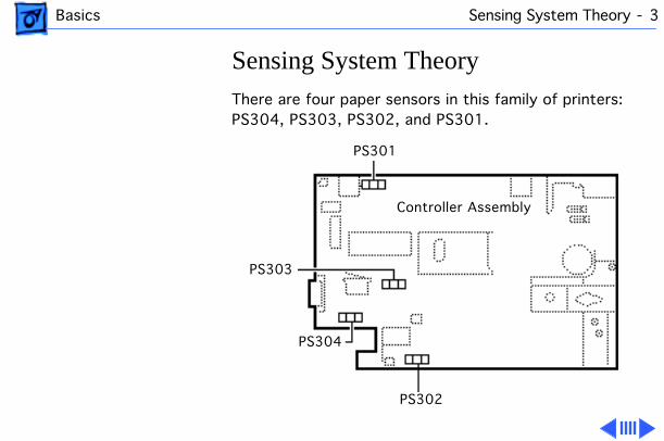
Sensing System Theory
There are four paper sensors in this family of printers: PS304, PS303, PS302, and PS301.
PS301
PS303
PS304
PS302
Controller Assembly
Basics Sensing System Theory - 4
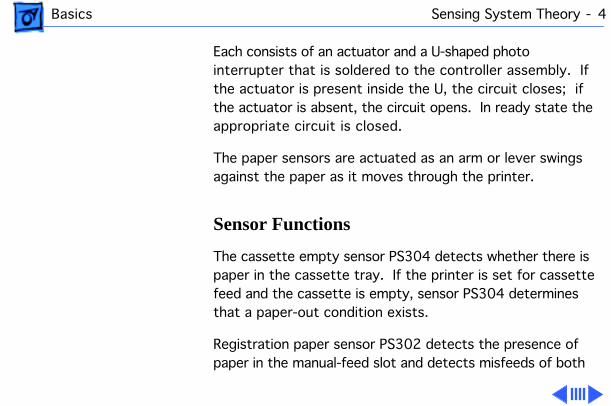
Each consists of an actuator and a U-shaped photo interrupter that is soldered to the controller assembly. If the actuator is present inside the U, the circuit closes; if the actuator is absent, the circuit opens. In ready state the appropriate circuit is closed.
The paper sensors are actuated as an arm or lever swings against the paper as it moves through the printer.
Sensor Functions
The cassette empty sensor PS304 detects whether there is paper in the cassette tray. If the printer is set for cassette feed and the cassette is empty, sensor PS304 determines that a paper-out condition exists.
Registration paper sensor PS302 detects the presence of paper in the manual-feed slot and detects misfeeds of both
Basics Sensing System Theory - 5
cassette-fed and manual-fed paper. If the paper does not reach the top position of this sensor in the required time, the printer determines that a pick-up delay jam has occurred.
Winding paper sensor PS303 detects the passage of paper from the photosensitive drum to the fuser. If the paper does not pass this sensor in time, the controller board determines that a jam condition exists.
Paper delivery sensor PS301 detects the passage of paper through the fuser assembly. If the paper does not pass this sensor in time, the controller board determines that a jam condition exists.
Basics Image Formation System - 6
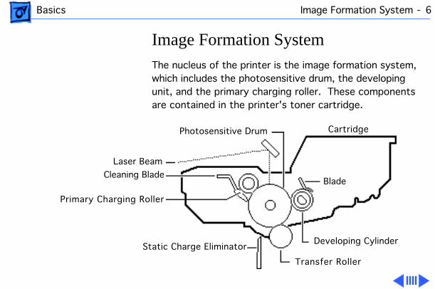
Image Formation System
The nucleus of the printer is the image formation system, which includes the photosensitive drum, the developing unit, and the primary charging roller. These components are contained in the printer's toner cartridge.
Cartridge
Laser Beam
Cleaning Blade
Primary Charging Roller
Static Charge Eliminator
Transfer Roller
Photosensitive Drum
Developing Cylinder
Blade
Basics Image Formation System - 7
The Printing Process
Upon receiving a print signal from the I/O board, the printer's controller assembly sends power to the main motor. The main motor, in turn, supplies the power that rotates the photosensitive drum, developing cylinder, primary charging roller, and transfer roller.
The primary charging roller applies a uniform negative charge on the photosensitive drum surface. At the same time, the laser/scanner assembly emits a laser beam that scans a latent image onto the surface of the photosensitive drum.
The latent image on the photosensitive drum becomes visible when the transfer roller transfers toner onto the developing cylinder.
Once the image is printed, the cleaner blade removes any
Basics Image Formation System - 8
residual toner on the photosensitive drum surface. Then, as a final step, the primary charging roller lays a uniform charge on the photosensitive drum, readying the drum for the next latent image.
Basics Status LEDs - 9
Status LEDs
The printer has three status LEDs: Ready/In Use, Paper-Out, and Paper-Jam.
While on standby, the printer's Ready/In Use status LED glows steadily. When a print command is received, the fan comes on and the Ready/In Use LED flashes.
If the cassette tray is empty and the printer is set for cassette feed, the Paper-Out LED glows steadily.
If paper is jammed in the printer, the Paper- Jam LED glows steadily.
Note:
The Personal LaserWriter 320 and LaserWriter 4/600 PS also use LEDs to indicate errors during diagnostic mode. Refer to "Engine Diagnostic" in Troubleshooting Tips.
Basics Status LEDs - 10
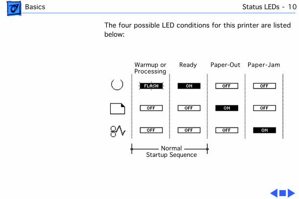
The four possible LED conditions for this printer are listed below:
Warmup orProcessing
Ready Paper-Out Paper-Jam
NormalStartup Sequence
Basics Toner Cartridge - 11
Toner Cartridge
Caution:
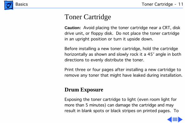
Avoid placing the toner cartridge near a CRT, disk drive unit, or floppy disk. Do not place the toner cartridge in an upright position or turn it upside down.
Before installing a new toner cartridge, hold the cartridge horizontally as shown and slowly rock it a 45° angle in both directions to evenly distribute the toner.
Print three or four pages after installing a new cartridge to remove any toner that might have leaked during installation.
Drum Exposure
Exposing the toner cartridge to light (even room light for more than 5 minutes) can damage the cartridge and may result in blank spots or black stripes on printed pages. To
Basics Toner Cartridge - 12
avoid such exposure:– Don't leave the rear access door open on the printer
when the toner cartridge is installed.– Always cover the toner cartridge when you remove it
from the printer. – Avoid storing opened toner packages in areas that are
exposed to direct sunlight.
Note:
If the cartridge has been irradiated by ordinary light, you may be able to repair the damage by placing the cartridge in a dark area, such as a drawer, for several hours. However, do not expose the cartridge to direct sunlight.
Basics LaserWriter Safety - 13
LaserWriter Safety
Unplug Printer
LaserWriter printers operate at high voltages. To prevent serious injury, always switch off the printer and unplug the AC power cord before servicing the printer.
Laser Beam Safety
Never disconnect the beam-detect cabling or laser shutter when the printer is switched on. Also be careful not to place screwdrivers or other shiny objects in the path of the laser beam. The reflected laser beam, though invisible, can permanently damage your eyes.
Never remove the cover of a laser/scanner assembly, whether the printer is powered on or not.
Basics LaserWriter Safety - 14
Fuser Heat
The fuser assembly becomes very hot during printer operation. Before servicing the fuser assembly, switch off the printer for at least 5 minutes to allow the fuser assembly to cool.
Toner Safety
Toner is a nontoxic substance composed of plastic, iron, and a small amount of pigment. Clean skin and clothing by removing as much toner as possible with a dry tissue and then washing with cold water. Hot water causes toner to jell and permanently fuse into clothing. Toner attacks vinyl materials, so avoid contact with vinyl.
Service Source
K
Specifications
PLW 300 & LW 4/600 PS
Specifications General - 1
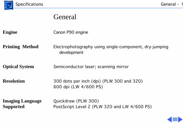
General
Engine
Canon P90 engine
Printing Method
Electrophotography using single-component, dry-jumping development
Optical System
Semiconductor laser; scanning mirror
Resolution
300 dots per inch (dpi) (PLW 300 and 320)600 dpi (LW 4/600 PS)
Imaging Language Supported
Quickdraw (PLW 300)PostScript Level 2 (PLW 320 and LW 4/600 PS)
Specifications General - 2
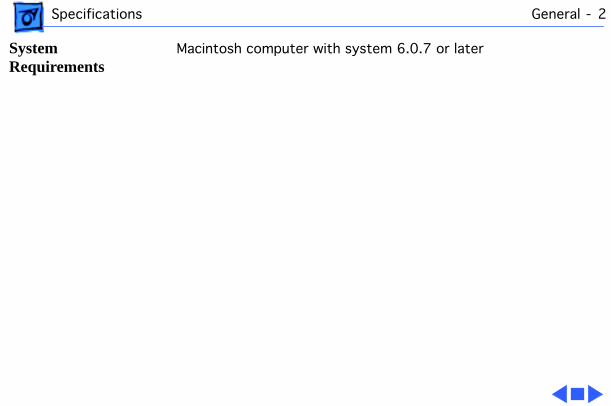
System Requirements
Macintosh computer with system 6.0.7 or later
Specifications Intro Date - 3
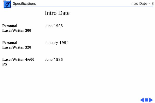
Intro Date
Personal LaserWriter 300
June 1993
Personal LaserWriter 320
January 1994
LaserWriter 4/600 PS
June 1995
Specifications Logic Board - 4
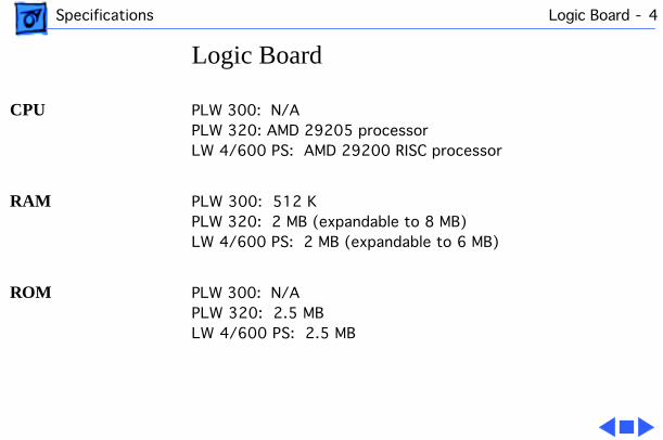
Logic Board
CPU
PLW 300: N/APLW 320: AMD 29205 processorLW 4/600 PS: AMD 29200 RISC processor
RAM
PLW 300: 512 KPLW 320: 2 MB (expandable to 8 MB)LW 4/600 PS: 2 MB (expandable to 6 MB)
ROM
PLW 300: N/APLW 320: 2.5 MBLW 4/600 PS: 2.5 MB
Specifications Logic Board - 5
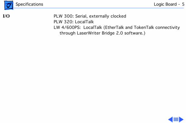
I/O
PLW 300: Serial, externally clockedPLW 320: LocalTalkLW 4/600PS: LocalTalk (EtherTalk and TokenTalk connectivity
through LaserWriter Bridge 2.0 software.)
Specifications Performance - 6
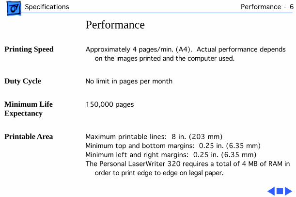
Performance
Printing Speed
Approximately 4 pages/min. (A4). Actual performance depends on the images printed and the computer used.
Duty Cycle
No limit in pages per month
Minimum Life Expectancy
150,000 pages
Printable Area
Maximum printable lines: 8 in. (203 mm)Minimum top and bottom margins: 0.25 in. (6.35 mm)Minimum left and right margins: 0.25 in. (6.35 mm) The Personal LaserWriter 320 requires a total of 4 MB of RAM in
order to print edge to edge on legal paper.
Specifications Paper - 7
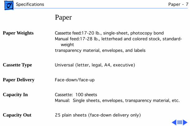
Paper
Paper Weights
Cassette feed:17-20 lb., single-sheet, photocopy bondManual feed:17-28 lb., letterhead and colored stock, standard-
weight transparency material, envelopes, and labels
Cassette Type
Universal (letter, legal, A4, executive)
Paper Delivery
Face-down/face-up
Capacity In
Cassette: 100 sheets Manual: Single sheets, envelopes, transparency material, etc.
Capacity Out
25 plain sheets (face-down delivery only)
Specifications Paper - 8
Transparency material, labels, and postcard paper are delivered face-up only and must be removed by hand.
Specifications Fonts - 9
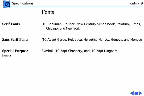
Fonts
Serif Fonts
ITC Bookman, Courier, New Century Schoolbook, Palatino, Times, Chicago, and New York
Sans Serif Fonts
ITC Avant Garde, Helvetica, Helvetica Narrow, Geneva, and Monaco
Special-Purpose Fonts
Symbol, ITC Zapf Chancery, and ITC Zapf Dingbats
Specifications Electrical - 10
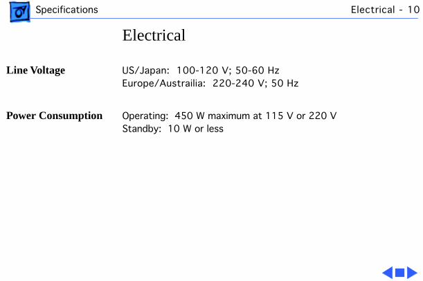
Electrical
Line Voltage
US/Japan: 100-120 V; 50-60 HzEurope/Austrailia: 220-240 V; 50 Hz
Power Consumption
Operating: 450 W maximum at 115 V or 220 VStandby: 10 W or less
Specifications Physical - 11
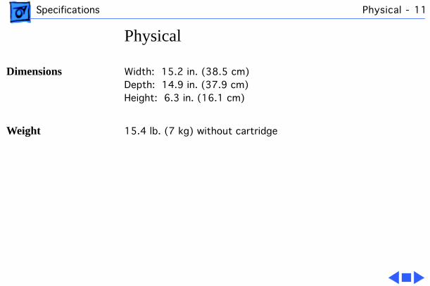
Physical
Dimensions
Width: 15.2 in. (38.5 cm)Depth: 14.9 in. (37.9 cm)Height: 6.3 in. (16.1 cm)
Weight
15.4 lb. (7 kg) without cartridge

Specifications Environmental - 12
Environmental
Temperature
Operating: 50-90.5° F (10-32.5° C)Storage: 32-95° F (0-35° C)
Humidity
Operating: 20-80% relative humidity, noncondensingStorage: 10-80% relative humidity, noncondensing
Ozone Emission
Less than 0.05 parts per million maximum, measured in accordance with ECMA 129 or UL114 standards for ozone
Service Source
K
Troubleshooting
PLW 300 & LW 4/600 PS
Troubleshooting General - 1
General
The first part of this chapter contains quick-reference troubleshooting information for the Personal LaserWriter 300/320 and LaserWriter 4/600 PS. We encourage you to review and print out this chapter before troubleshooting a printer.
At the end of this chapter are troubleshooting flowcharts and tables. If a table name clearly addresses your problem, you can go directly to that table. If not, you should go to the flowchart associated with the version of the printer you are working on.
Troubleshooting 320 Power-On Self Test - 2
320 Power-On Self Test
The Personal LaserWriter 320 goes through a self diagnostic each time that you plug the printer in. This diagnostic is called the Power-On Self Test (POST). This test is not the same as the engine diagnostic (see next topic). Unlike the engine diagnostic test, POST does not require the placement of any loopback cable.
Note:
POST does not occur on the Personal LaserWriter 300.
Observing how the LEDs extinguish from the time of startup can help isolate certain failure areas.
• When you plug in a functional printer, all LEDs will illuminate for a short time.
• The Ready LED extinguishes when no errors are found on the I/O controller board.
• The Paper-Out LED extinguishes when no errors are found on the RAM card.
Troubleshooting 320 Power-On Self Test - 3
• Finally the Jam LED extinguishes when no errors are found in the engine.
Note:
In a functional printer, control will be passed on to the PostScript interpreter at the end of this sequence.
Troubleshooting Engine Diagnostic - 4
Engine Diagnostic
The Personal LaserWriter 320 and LaserWriter 4/600 PS have self-diagnostic capability built into the I/O board. When the printer is in diagnostic mode, the LEDs are displayed in special diagnostic sequences.
Note:
The Personal LaserWriter 300 does not have self-diagnostic capability.
To enter the diagnostic mode, switch off the printer, place a serial loopback cable (P/N 922-1489) into the serial connector on the I/O board, and switch on the printer.
It may take up to 90 seconds for the diagnostic LEDs to display.
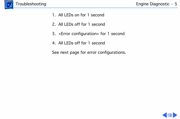
If the diagnostic detects an error, the LEDs will flash repeatedly through the following sequence until you switch off the printer.
Troubleshooting Engine Diagnostic - 5
1. All LEDs on for 1 second
2. All LEDs off for 1 second
3. <Error configuration> for 1 second
4. All LEDs off for 1 second
See next page for error configurations.
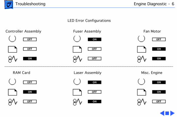
Troubleshooting Engine Diagnostic - 6
Controller Assembly Fuser Assembly Fan Motor
RAM Card Laser Assembly Misc. Engine
LED Error Configurations
Troubleshooting Troubleshooting Tips - 7
Troubleshooting Tips
Isolating Controller Board Problems
If you are unable to print a service test page (see "Service Test Page"), but the printer does cycle through its normal startup sequence (the fan comes on and the delivery rollers rotate), you most likely have a problem with the controller assembly or pickup solenoid.
Refer to the Take Apart chapter for instructions on how to replace the pickup solenoid and/or controller assembly.
Light Exposure Problems on Test Prints
When the printer cover is removed, the photosensitive drum inside the toner cartridge may be exposed to light. This exposure can affect the quality of your printouts.
Troubleshooting Troubleshooting Tips - 8
Guard against light exposure when printing service test pages and other printouts by covering the toner cartridge with a piece of paper.
Interrupting a Print Cycle
Interrupting a print cycle and inspecting the photosensitive drum can help isolate the cause of print quality problems.
If the image on the surface of the drum exhibits the same problem as the printed page, the fault is before the drum, probably somewhere in the imaging system.
If the image on the drum is OK, the fault is after the drum, probably in the fuser assembly or controller assembly.
To inspect the drum, initiate a printout. Wait approximately 12 seconds after you hear the paper being picked up from the casette tray and then interrupt the printing process.
Troubleshooting Troubleshooting Tips - 9
You should interrupt the printing process after the image has been transferred to the paper, but BEFORE the paper exits the fuser.
Remove the toner cartridge and turn it over. Pull back the shield that covers the photosensitive drum and inspect the drum surface.
Avoiding Paper Jams
The following tips will reduce your chances of a paper jam:
• Don't load already printed pages into the paper cassette—always use manual feed for printing the second side of two-sided copies.
• When printing multiple pages via manual feed, wait for the screen prompt before inserting a new sheet into the printer.
• Make sure that the paper cassette is properly loaded with one of the recommended paper types.
Troubleshooting Circuit Board Diagrams - 10
Circuit Board Diagrams
On the following pages are diagrams of the circuit boards and high-voltage contacts listed below:
• Personal LaserWriter 300 I/O Board
• Personal LaserWriter 320I/O Board
• Personal LaserWriter 320 2 MB RAM Expansion Card
• Personal LaserWriter 320 6 MB RAM Expansion Card
• Personal LaserWriter 300/320 Controller Assembly
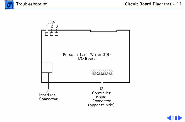
Troubleshooting Circuit Board Diagrams - 11
LEDs1 2 3
Personal LaserWriter 300I/O Board
J1InterfaceConnector
J2Controller
BoardConnector
(opposite side)
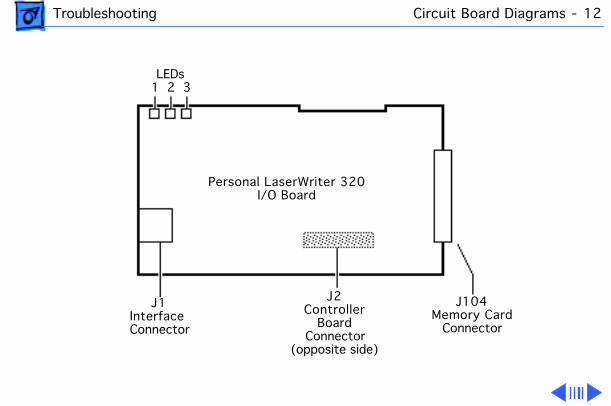
Troubleshooting Circuit Board Diagrams - 12
LEDs1 2 3
Personal LaserWriter 320I/O Board
J1InterfaceConnector
J2Controller
BoardConnector
(opposite side)
J104Memory Card
Connector
Troubleshooting Circuit Board Diagrams - 13
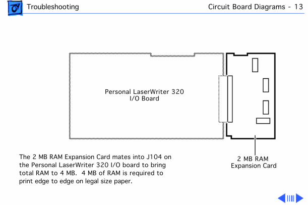
2 MB RAMExpansion Card
The 2 MB RAM Expansion Card mates into J104 onthe Personal LaserWriter 320 I/O board to bringtotal RAM to 4 MB. 4 MB of RAM is required toprint edge to edge on legal size paper.
Personal LaserWriter 320I/O Board
Troubleshooting Circuit Board Diagrams - 14
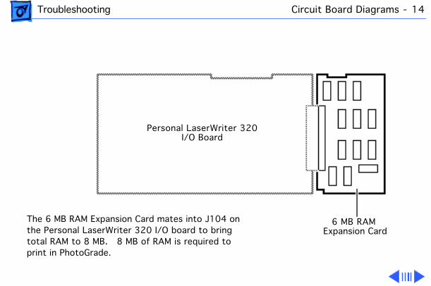
6 MB RAMExpansion Card
The 6 MB RAM Expansion Card mates into J104 onthe Personal LaserWriter 320 I/O board to bringtotal RAM to 8 MB. 8 MB of RAM is required toprint in PhotoGrade.
Personal LaserWriter 320I/O Board
Troubleshooting Circuit Board Diagrams - 15
J204SW301
J601
J202
SW201
J201
Pickup Solenoid
VR301
J206
J103
Fuses
HVT Assembly
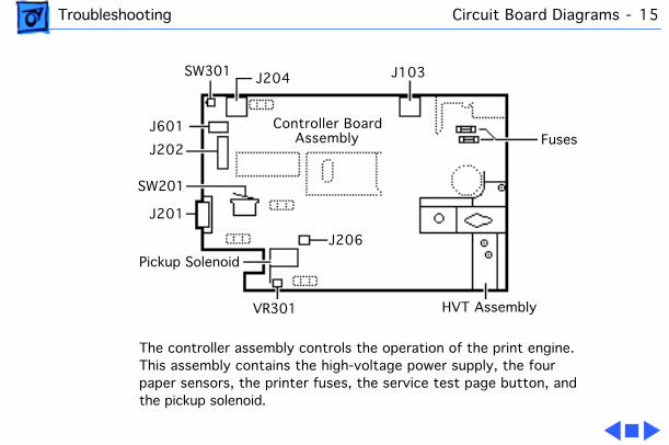
Controller BoardAssembly
The controller assembly controls the operation of the print engine. This assembly contains the high-voltage power supply, the four paper sensors, the printer fuses, the service test page button, and the pickup solenoid.
Troubleshooting Wiring Diagram - 16
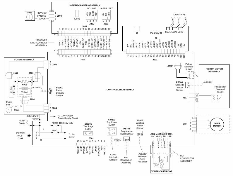
Wiring Diagram
The wiring diagram for this printer can be found on the next page. The detail in this document is too small to read easily at 100% view. You should either zoom into the diagram using the zoom tool above, or print the diagram on a laser printer with a resolution of 300 dpi (600 dpi preferred).
32
FUSER ASSEMBLY
J901
FAN 1J804FANTAC
+12VGND
MAINMOTOR
1 2 3 4 5 6 7 8 9 10 11 12
J202
13 14 15 16 17 18
GN
D(+
5V)
+5V
/VD
OU
T
/SC
NO
N
AP
CS
H
SC
NC
LK
GN
D
FA
NO
N+
12V
BS
GN
D
+12
VB
SF
AN
TA
CS
CN
TA
C
GN
D(+
5V)
LPC
HG
/BD
GN
D(+
5V)
+5V
FANON
1 2 3 4 5 6 7 8 9 10 11 12 13 14 15 16 17 18J801
J2
A1
B1
A2
B2
A3
B3
A4
B4
A5
B5
A6
B6
A7
B7
A8
B8
A9
B9
A10
B10
-5V
/BD
/PP
RD
Y/R
DY
/TO
P/S
BS
Y/S
TS
/PC
LK/C
BS
Y/P
RN
TG
ND
/CP
RD
Y/V
DO
/CM
D/C
CLK
/RE
SE
T/P
RF
D+
5VG
ND
+5V
I/O BOARDJ1 LED1 LED2 LED3
LIGHT PIPE+5V
/RO
GN
D/B
D
1 2 3 4
LD PD
+5V
1 2 3
BD UNIT LASER UNIT
IC801
J802 J803
321
FU
901
H901
TH901
J103
123
J204
J902
J904
R901
FixingFilm
J201
J206 Pickup
SolenoidSL002
CassetteEmptySensor
PS304
J207
Actuator
RegistrationSolenoidSL001
PICKUP MOTORASSEMBLY
J601
Safety EarthScrew
321
To Low VoltagePower Supply Circuit
J101
POWERINLET
PaperGuide
10 9 8 7 6 5 4 3 2 1
To ACDriver
AN
GN
DG
ND
PA
US
D12
VA
SF
SR
TH
RP
ISN
ST
OP
VR
FM
OD
EO
+5V
FM
OD
E1
J301
Test PageButton
Top CoverSwitch
VR301
RegistrationPaper Sensor
WindingPaperSensor
DV GND TR PRJ402 J404 J403 J401
PS302
PS303
HVTCONNECTORASSEMBLY
CoverInterlockActuator
ArmRegistrationAssembly
LASER/SCANNER ASSEMBLY
CONTROLLER ASSEMBLY
Actuatorin Feeder
Guide Assembly
TONER CARTRIDGE
1234
SCANNERINTERCONNECT
ASSEMBLY
PaperDeliverySensor
PS301Actuator
H
FU101
FU201 100/115V only SW301
SW201
Troubleshooting Service Test Page - 18
Service Test Page
The service test page is generated by the controller assembly. It serves to confirm print engine operation.
There are two methods for generating the service test page, depending on the model of the printer that you are servicing.
Troubleshooting Service Test Page - 19
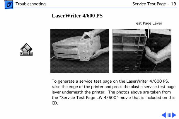
LaserWriter 4/600 PS
To generate a service test page on the LaserWriter 4/600 PS, raise the edge of the printer and press the plastic service test page lever underneath the printer. The photos above are taken from the “Service Test Page LW 4/600” movie that is included on this CD.
Test Page Lever
Troubleshooting Service Test Page - 20
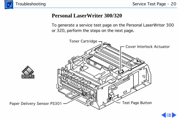
Personal LaserWriter 300/320
To generate a service test page on the Personal LaserWriter 300 or 320, perform the steps on the next page.
Cover Interlock Actuator
Test Page ButtonPaper Delivery Sensor PS301
Toner Cartridge
Troubleshooting Service Test Page - 21
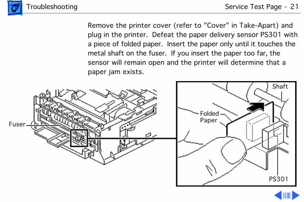
Remove the printer cover (refer to "Cover" in Take-Apart) and plug in the printer. Defeat the paper delivery sensor PS301 with a piece of folded paper. Insert the paper only until it touches the metal shaft on the fuser. If you insert the paper too far, the sensor will remain open and the printer will determine that a paper jam exists.
Fuser
FoldedPaper
Shaft
PS301
Troubleshooting Service Test Page - 22
Cover the toner cartridge with a piece of paper to prevent exposure of the drum.
Press down on the toner cartridge and the cover interlock actuator while you press the service test page button with a screwdriver (or similar dowel-shaped tool).
Note:
When you press down the cover interlock actuator, the fan should come on and the paper delivery rollers should rotate. If you don't hear the fan, verify that you have properly defeated the paper delivery sensor PS301, that you are holding down the cover interlock actuator all the way, and that the paper cassette is installed. If you do not press down firmly on the toner cartridge during the printing process, the test page may be blank.
Troubleshooting Power Failure - 23
Power Failure
AC power failure 1 Verify correct voltage at power outlet.2 Check power cord connections at printer and outlet.3 Replace fuse FU101 on controller assembly.4 Replace controller assembly.
DC power failure 1 Examine cause of tripping of overcurrent detection circuit in controller assembly.
2 Replace fuse FU201 on controller assembly.3 Replace controller assembly.
Troubleshooting No Paper Pickup - 24
No Paper Pickup
No pickup (manual feed)
1 Check arm registration assembly and replace if broken.2 Replace pickup motor assembly.3 Replace controller assembly.
No pickup (cassette feed)
1 Check cassette-empty sensor lever and replace if broken.2 Replace pickup solenoid on controller assembly.3 Inspect pickup roller on pickup motor assembly and replace
if damaged.4 Replace pickup motor assembly.5 Replace controller assembly.
Troubleshooting Printer Jams - 25
Printer Jams
Paper jam LED lights when there's no paper jam
1 Check arm registration assembly and replace if broken.2 Check paper delivery sensor and replace if broken.3 Replace controller assembly.
Troubleshooting Motor Failure - 26
Motor Failure
Motor doesn't rotate 1 Verify motor is making good contact with controller assembly at connector J601.
2 Replace main motor.3 Replace controller assembly.
Troubleshooting Fan Failure - 27
Fan Failure
Fan doesn't come on 1 Verify fan is making good contact with laser/scanner assembly at connector J804.
2 Replace fan.3 Replace controller assembly.

Troubleshooting Fuser Assembly Failure - 28
Fuser Assembly Failure
No power to fuser assembly
1 Verify fuser assembly is properly seated and making good contact with controller assembly at connectors J103 and J204.
2 Replace fuser assembly.
Note:
After replacing the fuser assembly, wait at least 10 minutes before plugging in the printer to allow the capacitor to discharge.
3 Replace controller assembly.
Troubleshooting Printer Drops After 3 Pages - 29
Printer Drops After 3 Pages
The printer drops connections to the Macintosh after printing three pages.
Replace the fan.
Troubleshooting Environmental Problems - 30
Environmental Problems
Room lights flicker when printer cycles to print.
There have been reports of the Personal LaserWriter 300/320 causing sporadic flickering in some incandescent lights when the printer cycles to print. Replacing the controller assembly has cured this problem in the cases that have been reported.
Flowcharts and TablesTroubleshooting
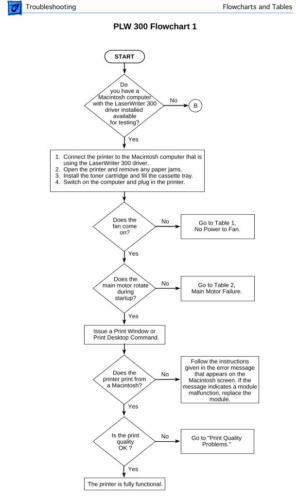
Yes
START
No
1. Connect the printer to the Macintosh computer that is using the LaserWriter 300 driver.2. Open the printer and remove any paper jams.3. Install the toner cartridge and fill the cassette tray.4. Switch on the computer and plug in the printer.
Does thefan come
on?
Does themain motor rotate
duringstartup?
Issue a Print Window orPrint Desktop Command.
Go to Table 1,No Power to Fan.
Go to Table 2,Main Motor Failure.
No
Yes
Yes
Do you have a
Macintosh computerwith the LaserWriter 300
driver installed available
for testing?
NoB
The printer is fully functional.
Yes
No
Does theprinter print from
a Macintosh?
Is the printqualityOK ?
Follow the instructionsgiven in the error message
that appears on theMacintosh screen. If the
message indicates a modulemalfunction, replace the
module.
Go to "Print QualityProblems."
No
Yes
PLW 300 Flowchart 1
Flowcharts and TablesTroubleshooting
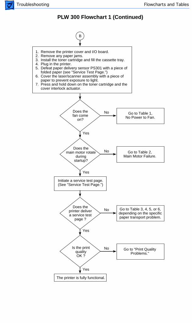
Yes
No
1. Remove the printer cover and I/O board.2. Remove any paper jams.3. Install the toner cartridge and fill the cassette tray.4. Plug in the printer.5. Defeat paper delivery sensor PS301 with a piece of folded paper (see "Service Test Page.")6. Cover the laser/scanner assembly with a piece of paper to prevent exposure to light.7. Press and hold down on the toner cartridge and the cover interlock actuator.
Does thefan come
on?
Does themain motor rotate
duringstartup?
Initiate a service test page.(See "Service Test Page.")
Go to Table 1,No Power to Fan.
Go to Table 2,Main Motor Failure.
No
Yes
The printer is fully functional.
Yes
No
Does theprinter delivera service test
page ?
Is the printqualityOK ?
Go to Table 3, 4, 5, or 6,depending on the specificpaper transport problem.
Go to "Print QualityProblems."
No
Yes
B
PLW 300 Flowchart 1 (Continued)
Flowcharts and TablesTroubleshooting
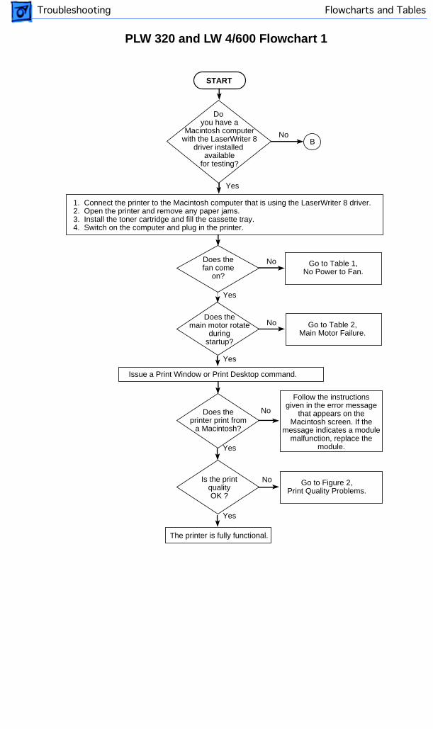
Yes
START
No
1. Connect the printer to the Macintosh computer that is using the LaserWriter 8 driver.2. Open the printer and remove any paper jams.3. Install the toner cartridge and fill the cassette tray.4. Switch on the computer and plug in the printer.
Does thefan come
on?
Does themain motor rotate
duringstartup?
Issue a Print Window or Print Desktop command.
Go to Table 1,No Power to Fan.
Go to Table 2,Main Motor Failure.
No
Yes
Yes
Do you have a
Macintosh computerwith the LaserWriter 8
driver installed available
for testing?
NoB
The printer is fully functional.
Yes
No
Does theprinter print from
a Macintosh?
Is the printqualityOK ?
Follow the instructionsgiven in the error message
that appears on theMacintosh screen. If the
message indicates a modulemalfunction, replace the
module.
Go to Figure 2,Print Quality Problems.
No
Yes
PLW 320 and LW 4/600 Flowchart 1
Flowcharts and TablesTroubleshooting
Yes
No
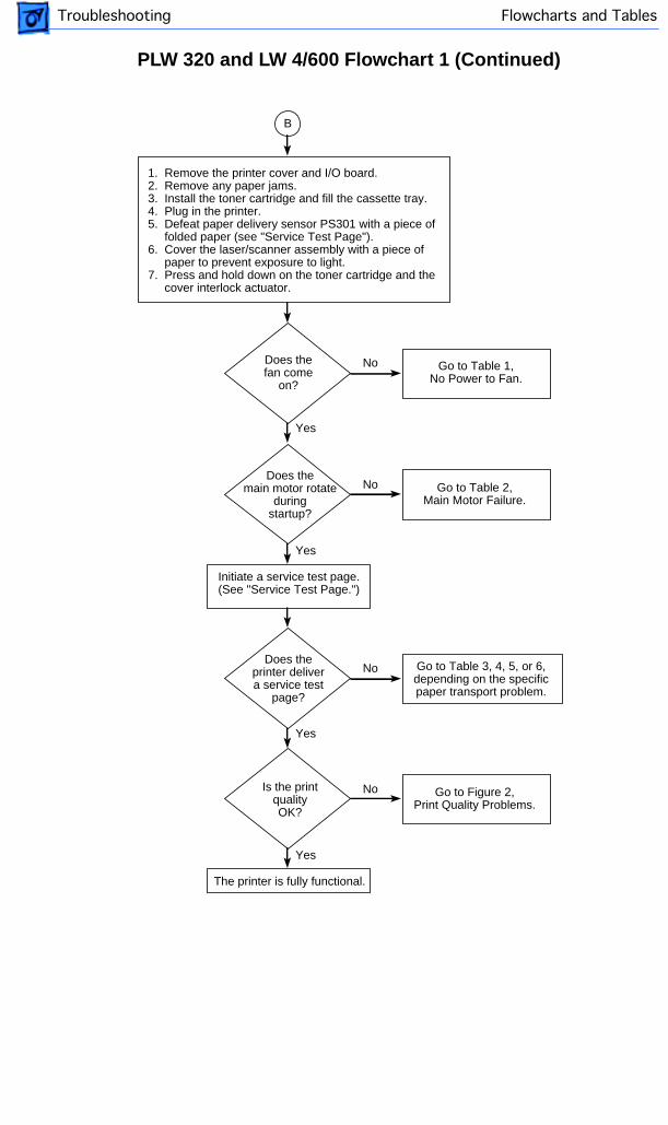
1. Remove the printer cover and I/O board.2. Remove any paper jams.3. Install the toner cartridge and fill the cassette tray.4. Plug in the printer.5. Defeat paper delivery sensor PS301 with a piece of folded paper (see "Service Test Page").6. Cover the laser/scanner assembly with a piece of paper to prevent exposure to light.7. Press and hold down on the toner cartridge and the cover interlock actuator.
Does thefan come
on?
Does themain motor rotate
duringstartup?
Initiate a service test page.(See "Service Test Page.")
Go to Table 1,No Power to Fan.
Go to Table 2,Main Motor Failure.
No
Yes
The printer is fully functional.
Yes
No
Does theprinter delivera service test
page?
Is the printqualityOK?
Go to Table 3, 4, 5, or 6,depending on the specificpaper transport problem.
Go to Figure 2,Print Quality Problems.
No
Yes
B
PLW 320 and LW 4/600 Flowchart 1 (Continued)
4
Flowcharts and TablesTroubleshooting
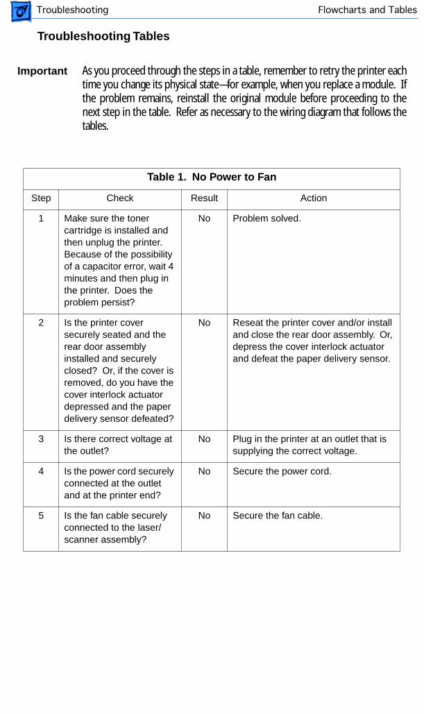
Important
As you proceed through the steps in a table, remember to retry the printer eachtime you change its physical state—for example, when you replace a module. Ifthe problem remains, reinstall the original module before proceeding to thenext step in the table. Refer as necessary to the wiring diagram that follows thetables.
Table 1. No Power to Fan
Step Check Result Action
1 Make sure the toner cartridge is installed and then unplug the printer. Because of the possibility of a capacitor error, wait 4 minutes and then plug in the printer. Does the problem persist?
No Problem solved.
2 Is the printer cover securely seated and the rear door assembly installed and securely closed? Or, if the cover is removed, do you have the cover interlock actuator depressed and the paper delivery sensor defeated?
No Reseat the printer cover and/or install and close the rear door assembly. Or, depress the cover interlock actuator and defeat the paper delivery sensor.
3 Is there correct voltage at the outlet?
No Plug in the printer at an outlet that is supplying the correct voltage.
4 Is the power cord securely connected at the outlet and at the printer end?
No Secure the power cord.
5 Is the fan cable securely connected to the laser/scanner assembly?
No Secure the fan cable.
Troubleshooting Tables
Flowcharts and TablesTroubleshooting
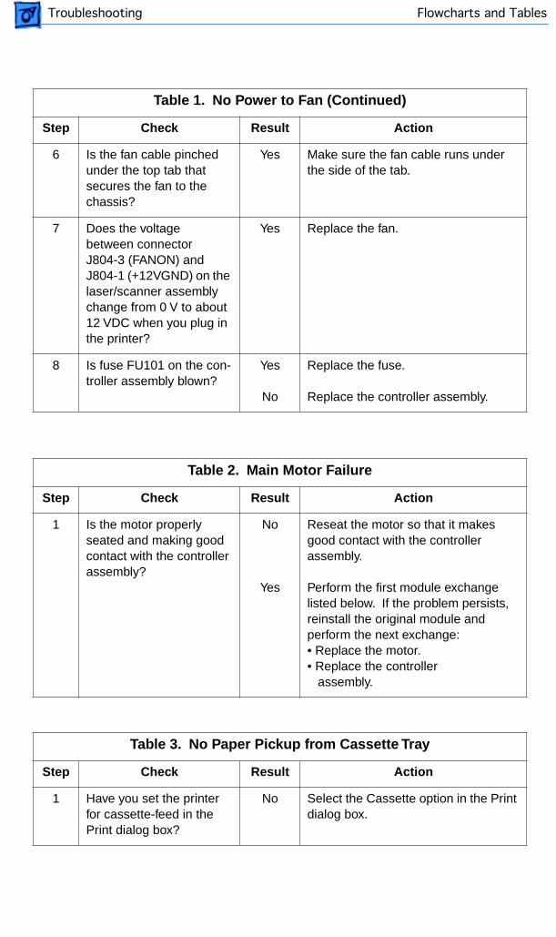
Table 1. No Power to Fan (Continued)
Step Check Result Action
6 Is the fan cable pinched under the top tab that secures the fan to the chassis?
Yes Make sure the fan cable runs under the side of the tab.
7 Does the voltage between connector J804-3 (FANON) and J804-1 (+12VGND) on the laser/scanner assembly change from 0 V to about 12 VDC when you plug in the printer?
Yes Replace the fan.
8 Is fuse FU101 on the con-troller assembly blown?
Yes
No
Replace the fuse.
Replace the controller assembly.
Table 2. Main Motor Failure
Step Check Result Action
1 Is the motor properly seated and making good contact with the controller assembly?
No
Yes
Reseat the motor so that it makes good contact with the controller assembly.
Perform the first module exchange listed below. If the problem persists, reinstall the original module and perform the next exchange:• Replace the motor.• Replace the controller assembly.
Table 3. No Paper Pickup from Cassette Tray
Step Check Result Action
1 Have you set the printer for cassette-feed in the Print dialog box?
No Select the Cassette option in the Print dialog box.

4
Flowcharts and TablesTroubleshooting
Table 3. No Paper Pickup from Cassette Tray (Continued)
Step Check Result Action
2 Was the toner cartridge installed before you plugged in the printer?
No With the toner cartridge installed, unplug the printer and plug it back in again.
3 Try printing with known-good paper. Does the problem persist?
No Problem solved.
4 Remove excess paper from the cassette tray. Does the problem persist?
No Problem solved.
5 Is the paper pickup roller worn or deformed?
Yes Replace the paper pickup roller.
6 Replace the pickup solenoid on the controller assembly. Does the problem persist?
No Problem solved.
7 Is the fuser assembly properly seated and making good contact with the controller assembly?
No Reseat the fuser assembly so that it makes good contact with the controller assembly.
8 Remove the fuser assembly and measure the resistance between connectors J204-1 and J204-2.
Does the resistance measure approximately 440 k
Ω
?
No Replace the fuser assembly.
9 Is there continuity between connectors J103-1 and J103-2?
No
Yes
Replace the fuser assembly.
Perform the first module exchange listed below. If the problem persists, reinstall the original module and perform the next exchange:• Replace the controller assembly• Replace the pickup motor.
Flowcharts and TablesTroubleshooting
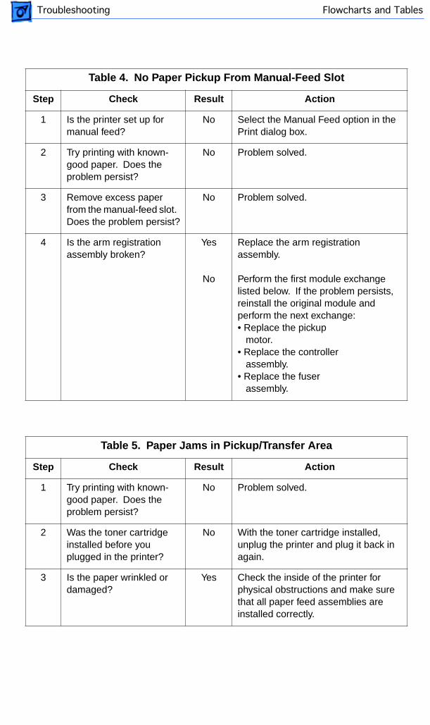
Table 4. No Paper Pickup From Manual-Feed Slot
Step Check Result Action
1 Is the printer set up for manual feed?
No Select the Manual Feed option in the Print dialog box.
2 Try printing with known-good paper. Does the problem persist?
No Problem solved.
3 Remove excess paper from the manual-feed slot. Does the problem persist?
No Problem solved.
4 Is the arm registration assembly broken?
Yes
No
Replace the arm registration assembly.
Perform the first module exchange listed below. If the problem persists, reinstall the original module and perform the next exchange:• Replace the pickup motor.• Replace the controller assembly.• Replace the fuser assembly.
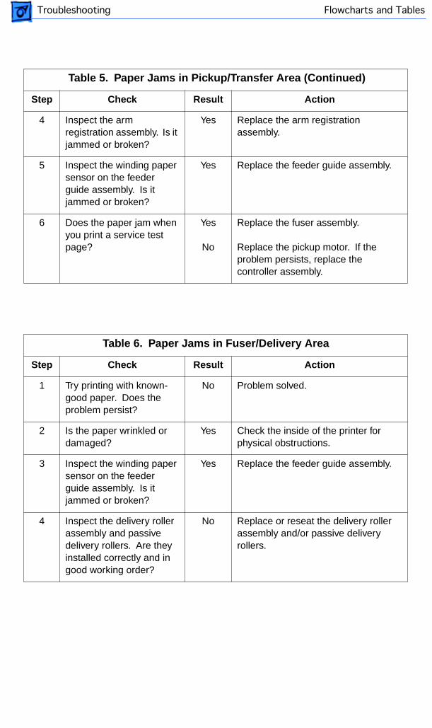
Table 5. Paper Jams in Pickup/Transfer Area
Step Check Result Action
1 Try printing with known-good paper. Does the problem persist?
No Problem solved.
2 Was the toner cartridge installed before you plugged in the printer?
No With the toner cartridge installed, unplug the printer and plug it back in again.
3 Is the paper wrinkled or damaged?
Yes Check the inside of the printer for physical obstructions and make sure that all paper feed assemblies are installed correctly.
4
Flowcharts and TablesTroubleshooting
Table 5. Paper Jams in Pickup/Transfer Area (Continued)
Step Check Result Action
4 Inspect the arm registration assembly. Is it jammed or broken?
Yes Replace the arm registration assembly.
5 Inspect the winding paper sensor on the feeder guide assembly. Is it jammed or broken?
Yes Replace the feeder guide assembly.
6 Does the paper jam when you print a service test page?
Yes
No
Replace the fuser assembly.
Replace the pickup motor. If the problem persists, replace the controller assembly.
Table 6. Paper Jams in Fuser/Delivery Area
Step Check Result Action
1 Try printing with known-good paper. Does the problem persist?
No Problem solved.
2 Is the paper wrinkled or damaged?
Yes Check the inside of the printer for physical obstructions.
3 Inspect the winding paper sensor on the feeder guide assembly. Is it jammed or broken?
Yes Replace the feeder guide assembly.
4 Inspect the delivery roller assembly and passive delivery rollers. Are they installed correctly and in good working order?
No Replace or reseat the delivery roller assembly and/or passive delivery rollers.

Flowcharts and TablesTroubleshooting
Table 6. Paper Jams in Fuser/Delivery Area (Continued)
Step Check Result Action
5 Remove the rear door assembly and inspect the operation of the paper delivery selector. Does the assembly move freely?
No Replace the rear door assembly.
6 Test the paper delivery sensor in the fuser assembly. Does it appear to be jammed or broken?
Yes
No
Replace the fuser assembly.
Replace the controller assembly. If the problem persists, replace the fuser assembly.
Flowcharts and TablesTroubleshooting
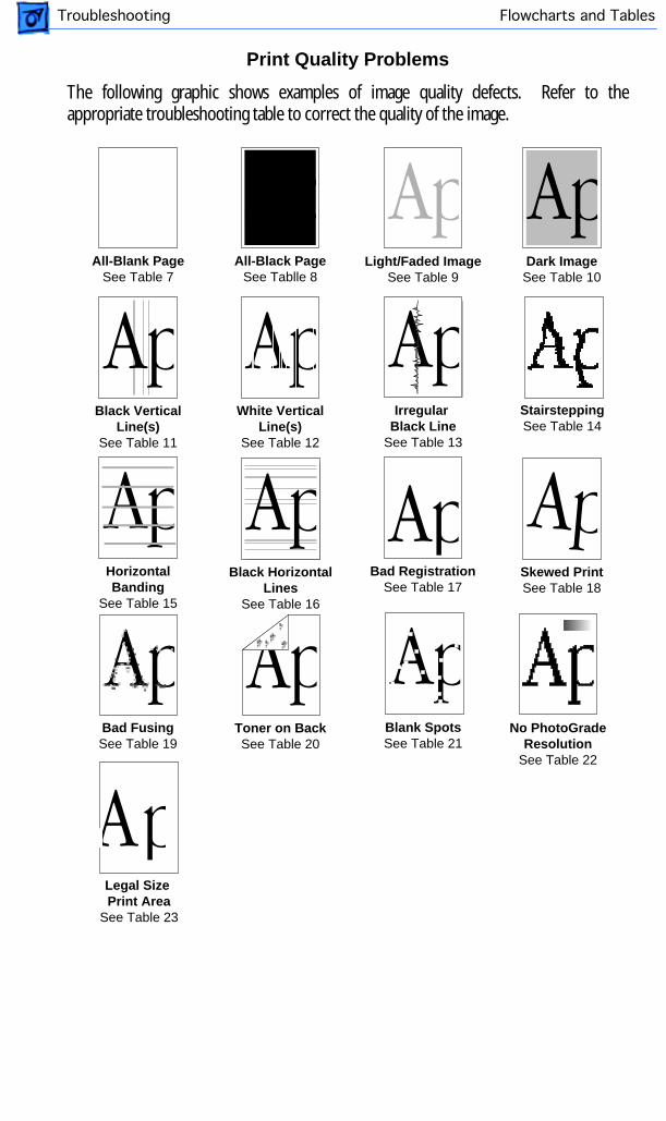
All-Blank PageSee Table 7
Light/Faded ImageSee Table 9
Black VerticalLine(s)
See Table 11
HorizontalBanding
See Table 15
Bad RegistrationSee Table 17
Bad FusingSee Table 19
Toner on BackSee Table 20
All-Black PageSee Tablle 8
Dark ImageSee Table 10
White VerticalLine(s)
See Table 12
Black HorizontalLines
See Table 16
StairsteppingSee Table 14
Blank SpotsSee Table 21
Skewed PrintSee Table 18
Irregular Black Line
See Table 13
Legal Size Print Area
See Table 23
No PhotoGradeResolution
See Table 22
Print Quality Problems
The following graphic shows examples of image quality defects. Refer to theappropriate troubleshooting table to correct the quality of the image.
Flowcharts and TablesTroubleshooting
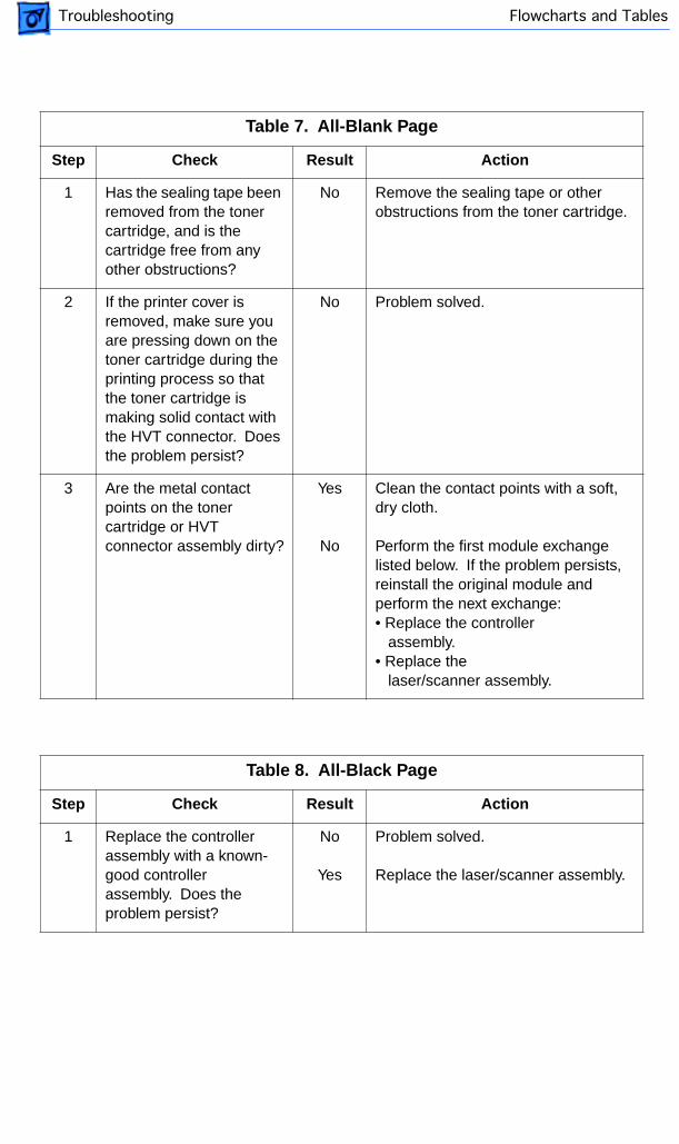
Table 7. All-Blank Page
Step Check Result Action
1 Has the sealing tape been removed from the toner cartridge, and is the cartridge free from any other obstructions?
No Remove the sealing tape or other obstructions from the toner cartridge.
2 If the printer cover is removed, make sure you are pressing down on the toner cartridge during the printing process so that the toner cartridge is making solid contact with the HVT connector. Does the problem persist?
No Problem solved.
3 Are the metal contact points on the toner cartridge or HVT connector assembly dirty?
Yes
No
Clean the contact points with a soft, dry cloth.
Perform the first module exchange listed below. If the problem persists, reinstall the original module and perform the next exchange:• Replace the controller assembly.• Replace the laser/scanner assembly.
Table 8. All-Black Page
Step Check Result Action
1 Replace the controller assembly with a known-good controller assembly. Does the problem persist?
No
Yes
Problem solved.
Replace the laser/scanner assembly.
4
Flowcharts and TablesTroubleshooting
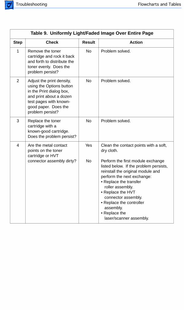
Table 9. Uniformly Light/Faded Image Over Entire Page
Step Check Result Action
1 Remove the toner cartridge and rock it back and forth to distribute the toner evenly. Does the problem persist?
No Problem solved.
2 Adjust the print density, using the Options button in the Print dialog box, and print about a dozen test pages with known-good paper. Does the problem persist?
No Problem solved.
3 Replace the toner cartridge with a known-good cartridge. Does the problem persist?
No Problem solved.
4 Are the metal contact points on the toner cartridge or HVT connector assembly dirty?
Yes
No
Clean the contact points with a soft, dry cloth.
Perform the first module exchange listed below. If the problem persists, reinstall the original module and perform the next exchange:• Replace the transfer roller assembly.• Replace the HVT connector assembly.• Replace the controller assembly.• Replace the laser/scanner assembly.
Flowcharts and TablesTroubleshooting
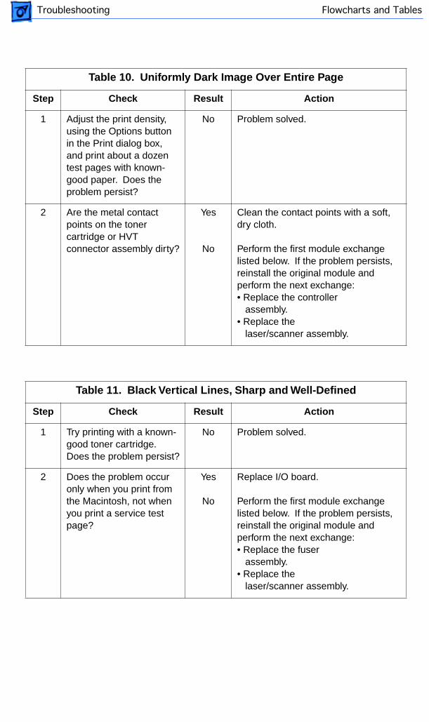
Table 10. Uniformly Dark Image Over Entire Page
Step Check Result Action
1 Adjust the print density, using the Options button in the Print dialog box, and print about a dozen test pages with known-good paper. Does the problem persist?
No Problem solved.
2 Are the metal contact points on the toner cartridge or HVT connector assembly dirty?
Yes
No
Clean the contact points with a soft, dry cloth.
Perform the first module exchange listed below. If the problem persists, reinstall the original module and perform the next exchange:• Replace the controller assembly.• Replace the laser/scanner assembly.
Table 11. Black Vertical Lines, Sharp and Well-Defined
Step Check Result Action
1 Try printing with a known-good toner cartridge. Does the problem persist?
No Problem solved.
2 Does the problem occur only when you print from the Macintosh, not when you print a service test page?
Yes
No
Replace I/O board.
Perform the first module exchange listed below. If the problem persists, reinstall the original module and perform the next exchange:• Replace the fuser assembly.• Replace the laser/scanner assembly.
4
Flowcharts and TablesTroubleshooting
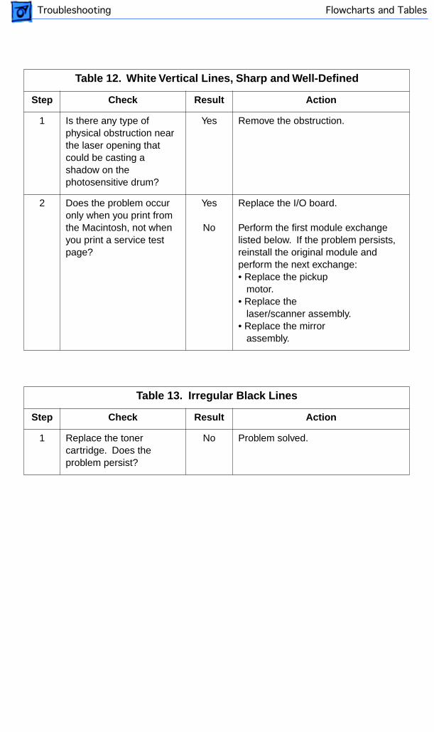
Table 12. White Vertical Lines, Sharp and Well-Defined
Step Check Result Action
1 Is there any type of physical obstruction near the laser opening that could be casting a shadow on the photosensitive drum?
Yes Remove the obstruction.
2 Does the problem occur only when you print from the Macintosh, not when you print a service test page?
Yes
No
Replace the I/O board.
Perform the first module exchange listed below. If the problem persists, reinstall the original module and perform the next exchange:• Replace the pickup motor.• Replace the laser/scanner assembly.• Replace the mirror assembly.
Table 13. Irregular Black Lines
Step Check Result Action
1 Replace the toner cartridge. Does the problem persist?
No Problem solved.
Flowcharts and TablesTroubleshooting
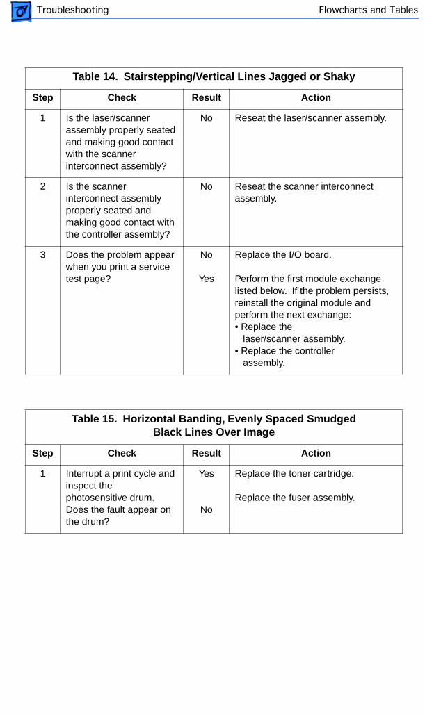
Table 14. Stairstepping/Vertical Lines Jagged or Shaky
Step Check Result Action
1 Is the laser/scanner assembly properly seated and making good contact with the scanner interconnect assembly?
No Reseat the laser/scanner assembly.
2 Is the scanner interconnect assembly properly seated and making good contact with the controller assembly?
No Reseat the scanner interconnect assembly.
3 Does the problem appear when you print a service test page?
No
Yes
Replace the I/O board.
Perform the first module exchange listed below. If the problem persists, reinstall the original module and perform the next exchange:• Replace the laser/scanner assembly.• Replace the controller assembly.
Table 15. Horizontal Banding, Evenly Spaced Smudged Black Lines Over Image
Step Check Result Action
1 Interrupt a print cycle and inspect the photosensitive drum. Does the fault appear on the drum?
Yes
No
Replace the toner cartridge.
Replace the fuser assembly.
4
Flowcharts and TablesTroubleshooting
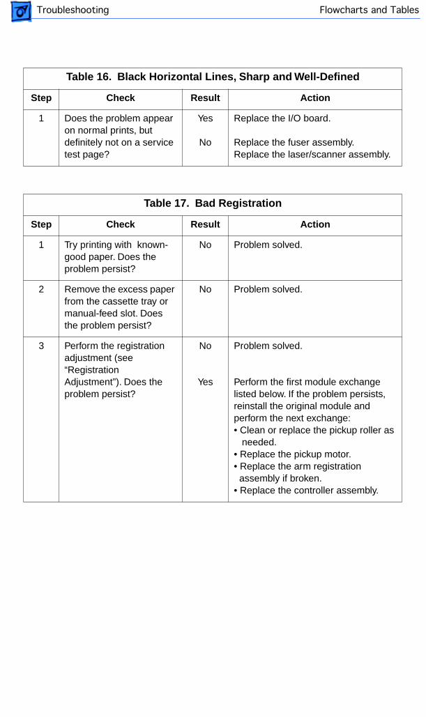
Table 16. Black Horizontal Lines, Sharp and Well-Defined
Step Check Result Action
1 Does the problem appear on normal prints, but definitely not on a service test page?
Yes
No
Replace the I/O board.
Replace the fuser assembly.Replace the laser/scanner assembly.
Table 17. Bad Registration
Step Check Result Action
1 Try printing with known-good paper. Does the problem persist?
No Problem solved.
2 Remove the excess paper from the cassette tray or manual-feed slot. Does the problem persist?
No Problem solved.
3 Perform the registration adjustment (see “Registration Adjustment”). Does the problem persist?
No
Yes
Problem solved.
Perform the first module exchange listed below. If the problem persists, reinstall the original module and perform the next exchange:• Clean or replace the pickup roller as needed.• Replace the pickup motor.• Replace the arm registration assembly if broken.• Replace the controller assembly.
Flowcharts and TablesTroubleshooting
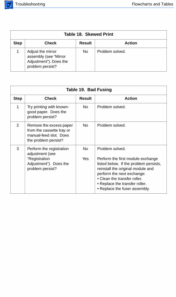
Table 18. Skewed Print
Step Check Result Action
1 Adjust the mirror assembly (see “Mirror Adjustment”). Does the problem persist?
No Problem solved.
Table 19. Bad Fusing
Step Check Result Action
1 Try printing with known-good paper. Does the problem persist?
No Problem solved.
2 Remove the excess paper from the cassette tray or manual-feed slot. Does the problem persist?
No Problem solved.
3 Perform the registration adjustment (see “Registration Adjustment”). Does the problem persist?
No
Yes
Problem solved.
Perform the first module exchange listed below. If the problem persists, reinstall the original module and perform the next exchange:• Clean the transfer roller.• Replace the transfer roller.• Replace the fuser assembly.
4
Flowcharts and TablesTroubleshooting
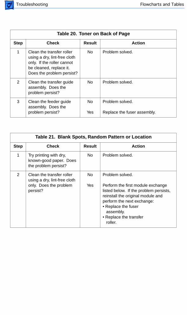
Table 20. Toner on Back of Page
Step Check Result Action
1 Clean the transfer roller using a dry, lint-free cloth only. If the roller cannot be cleaned, replace it. Does the problem persist?
No Problem solved.
2 Clean the transfer guide assembly. Does the problem persist?
No Problem solved.
3 Clean the feeder guide assembly. Does the problem persist?
No
Yes
Problem solved.
Replace the fuser assembly.
Table 21. Blank Spots, Random Pattern or Location
Step Check Result Action
1 Try printing with dry, known-good paper. Does the problem persist?
No Problem solved.
2 Clean the transfer roller using a dry, lint-free cloth only. Does the problem persist?
No
Yes
Problem solved.
Perform the first module exchange listed below. If the problem persists, reinstall the original module and perform the next exchange:• Replace the fuser assembly.• Replace the transfer roller.
Flowcharts and TablesTroubleshooting
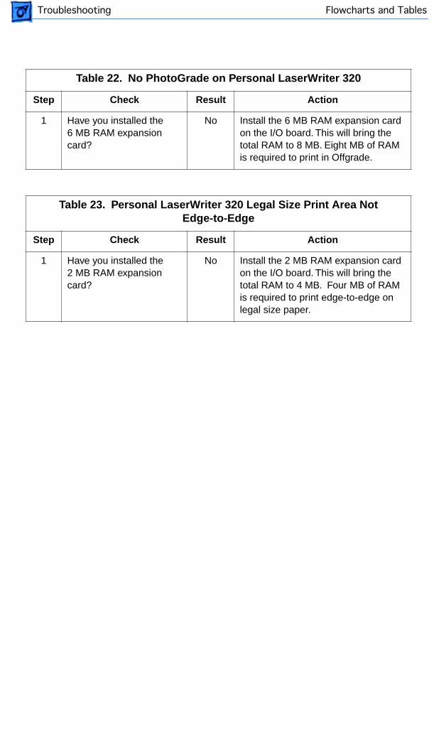
Table 22. No PhotoGrade on Personal LaserWriter 320
Step Check Result Action
1 Have you installed the 6 MB RAM expansion card?
No Install the 6 MB RAM expansion card on the I/O board. This will bring the total RAM to 8 MB. Eight MB of RAM is required to print in Offgrade.
Table 23. Personal LaserWriter 320 Legal Size Print Area Not Edge-to-Edge
Step Check Result Action
1 Have you installed the 2 MB RAM expansion card?
No Install the 2 MB RAM expansion card on the I/O board. This will bring the total RAM to 4 MB. Four MB of RAM is required to print edge-to-edge on legal size paper.
Service Source
K
Take Apart
PLW 300 & LW 4/600 PS
Take Apart Connector Covers - 1
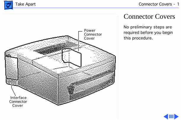
Connector Covers
No preliminary steps are required before you begin this procedure.
PowerConnectorCover
InterfaceConnector
Cover
Take Apart Connector Covers - 2
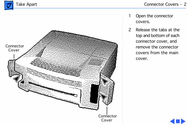
1 Open the connector covers.
2 Release the tabs at the top and bottom of each connector cover, and remove the connector covers from the main cover.
ConnectorCover
ConnectorCover
Take Apart Rear Door Assembly - 3
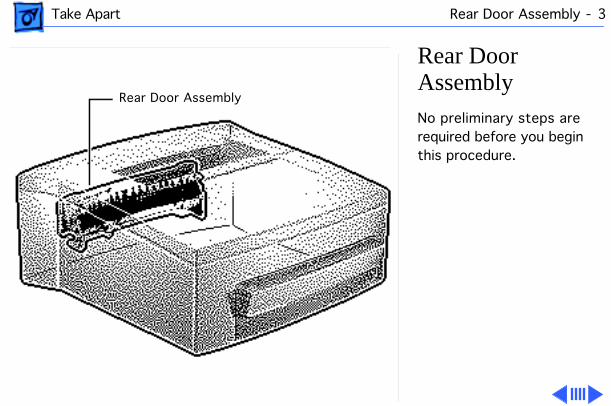
Rear Door Assembly
No preliminary steps are required before you begin this procedure.
Rear Door Assembly
Take Apart Rear Door Assembly - 4
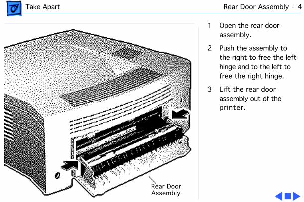
1 Open the rear door assembly.
2 Push the assembly to the right to free the left hinge and to the left to free the right hinge.
3 Lift the rear door assembly out of the printer.
Rear DoorAssembly
Take Apart Cover - 5
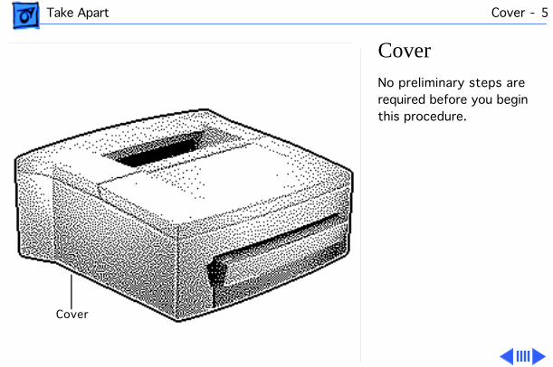
Cover
No preliminary steps are required before you begin this procedure.
Cover
Take Apart Cover - 6
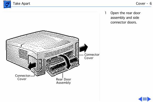
1 Open the rear door assembly and side connector doors.
ConnectorCover
Rear DoorAssembly
ConnectorCover
Take Apart Cover - 7
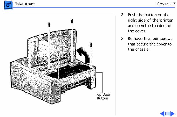
2 Push the button on the right side of the printer and open the top door of the cover.
3 Remove the four screws that secure the cover to the chassis.
Top DoorButton
Take Apart Cover - 8
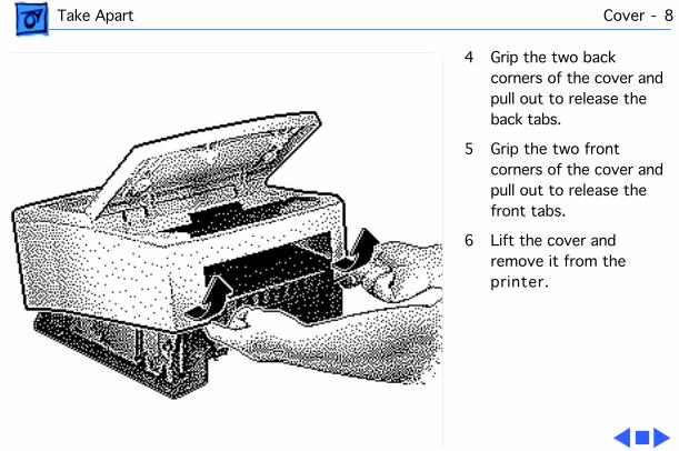
4 Grip the two back corners of the cover and pull out to release the back tabs.
5 Grip the two front corners of the cover and pull out to release the front tabs.
6 Lift the cover and remove it from the printer.

Take Apart Light Pipe - 9
Light Pipe
Before you begin, remove the cover.
Light Pipe
Take Apart Light Pipe - 10
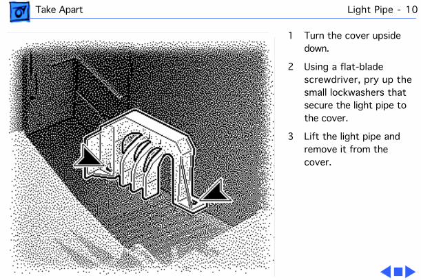
1 Turn the cover upside down.
2 Using a flat-blade screwdriver, pry up the small lockwashers that secure the light pipe to the cover.
3 Lift the light pipe and remove it from the cover.
Take Apart Top Door Assembly - 11
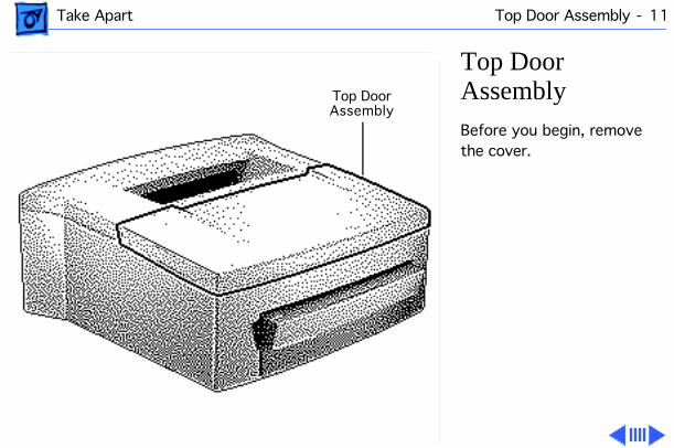
Top Door Assembly
Before you begin, remove the cover.
Top DoorAssembly
Take Apart Top Door Assembly - 12
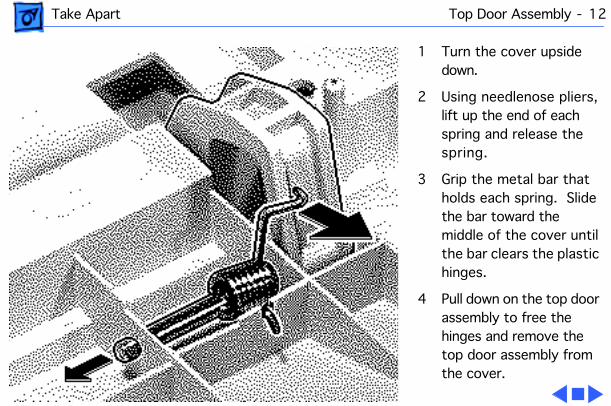
1 Turn the cover upside down.
2 Using needlenose pliers, lift up the end of each spring and release the spring.
3 Grip the metal bar that holds each spring. Slide the bar toward the middle of the cover until the bar clears the plastic hinges.
4 Pull down on the top door assembly to free the hinges and remove the top door assembly from the cover.

Take Apart Button Lock Assembly - 13
Button Lock Assembly
Before you begin, remove the cover.
ButtonLock
Assembly
Take Apart Button Lock Assembly - 14
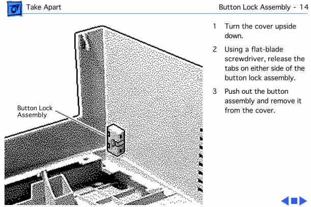
1 Turn the cover upside down.
2 Using a flat-blade screwdriver, release the tabs on either side of the button lock assembly.
3 Push out the button assembly and remove it from the cover.Button Lock
Assembly
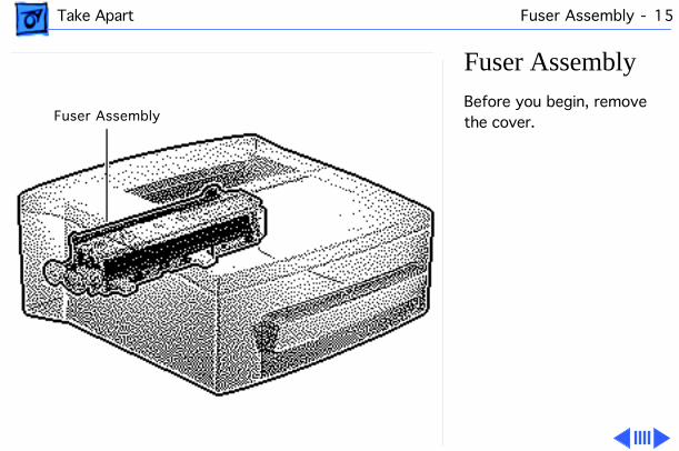
Take Apart Fuser Assembly - 15
Fuser Assembly
Before you begin, remove the cover.Fuser Assembly
Take Apart Fuser Assembly - 16
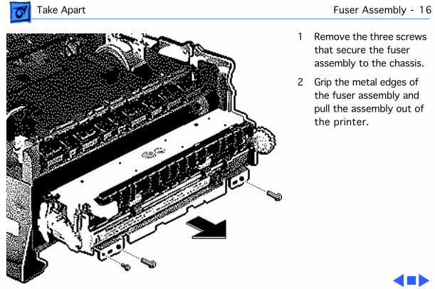
1 Remove the three screws that secure the fuser assembly to the chassis.
2 Grip the metal edges of the fuser assembly and pull the assembly out of the printer.
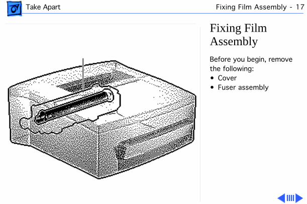
Take Apart Fixing Film Assembly - 17
Fixing Film Assembly
Before you begin, remove the following:• Cover• Fuser assembly
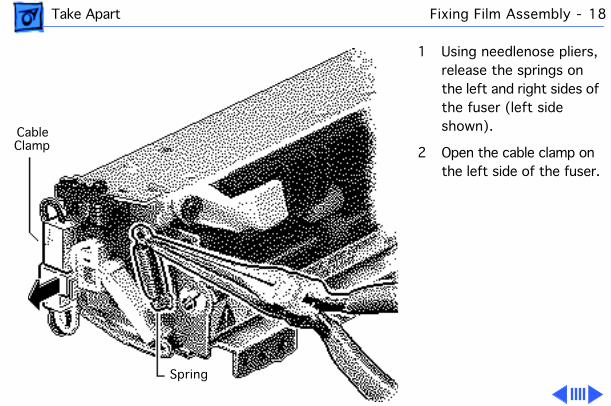
Take Apart Fixing Film Assembly - 18
1 Using needlenose pliers, release the springs on the left and right sides of the fuser (left side shown).
2 Open the cable clamp on the left side of the fuser.
Spring
CableClamp
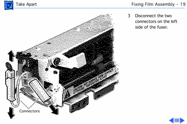
Take Apart Fixing Film Assembly - 19
3 Disconnect the two connectors on the left side of the fuser.
Connectors
Take Apart Fixing Film Assembly - 20
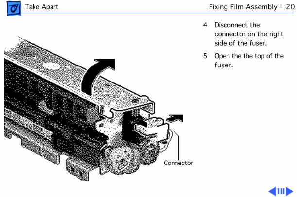
4 Disconnect the connector on the right side of the fuser.
5 Open the the top of the fuser.
Connector
Take Apart Fixing Film Assembly - 21
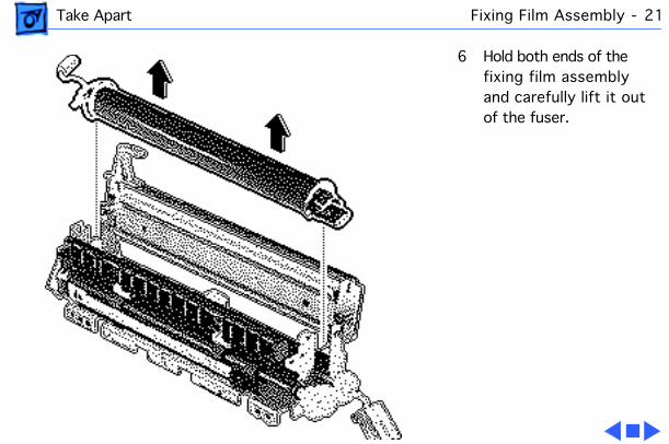
6 Hold both ends of the fixing film assembly and carefully lift it out of the fuser.

Take Apart Delivery Roller Assembly - 22
Delivery Roller Assembly
Before you begin, remove the cover.
Delivery RollerAssembly

Take Apart Delivery Roller Assembly - 23
1 Using a flat-blade screwdriver, release the white plastic tab that holds one side of the delivery roller assembly.
2 Pull up on the roller to free that side from the chassis.
3 Repeat this procedure on the other side of the roller.
4 Remove the roller assembly from the chassis.
Tab
Take Apart Passive Delivery Rollers - 24
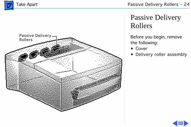
Passive Delivery Rollers
Before you begin, remove the following:• Cover• Delivery roller assembly
Passive DeliveryRollers
Take Apart Passive Delivery Rollers - 25
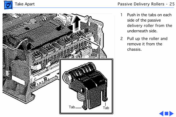
1 Push in the tabs on each side of the passive delivery roller from the underneath side.
2 Pull up the roller and remove it from the chassis.
TabTab
Take Apart Laser/Scanner Assembly - 26
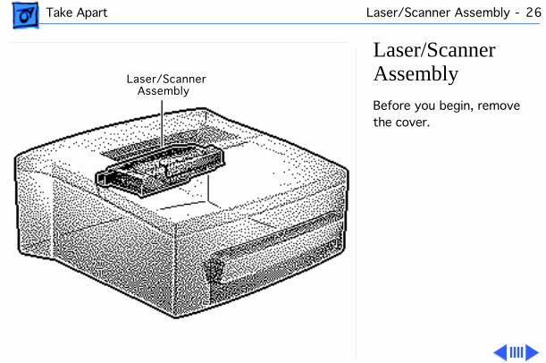
Laser/Scanner Assembly
Before you begin, remove the cover.
Laser/ScannerAssembly
Take Apart Laser/Scanner Assembly - 27
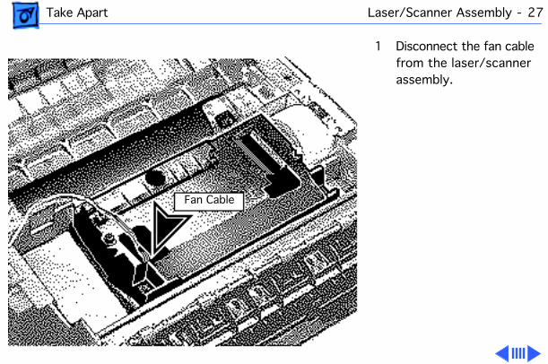
1 Disconnect the fan cable from the laser/scanner assembly.
Fan Cable
Take Apart Laser/Scanner Assembly - 28
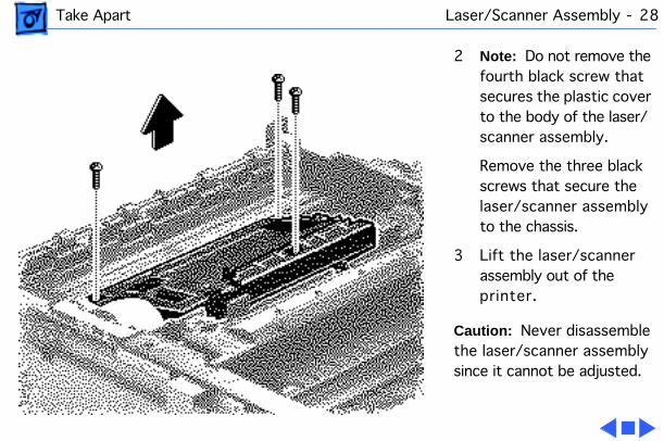
2
Note:
Do not remove the fourth black screw that secures the plastic cover to the body of the laser/scanner assembly.
Remove the three black screws that secure the laser/scanner assembly to the chassis.
3 Lift the laser/scanner assembly out of the printer.
Caution:
Never disassemble the laser/scanner assembly since it cannot be adjusted.
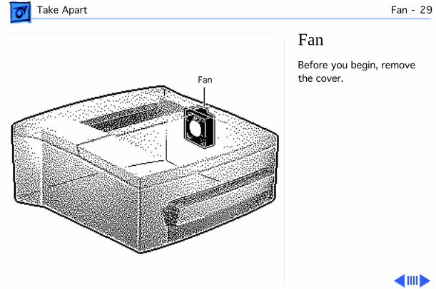
Take Apart Fan - 29
Fan
Before you begin, remove the cover.Fan
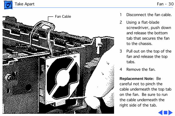
Take Apart Fan - 30
1 Disconnect the fan cable.
2 Using a flat-blade screwdriver, push down and release the bottom tab that secures the fan to the chassis.
3 Pull out on the top of the fan and release the top tabs.
4 Remove the fan.
Replacement Note:
Be careful not to pinch the cable underneath the top tab on the fan. Be sure to run the cable underneath the right side of the tab.
Fan Cable
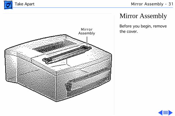
Take Apart Mirror Assembly - 31
Mirror Assembly
Before you begin, remove the cover.Mirror
Assembly
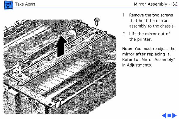
Take Apart Mirror Assembly - 32
1 Remove the two screws that hold the mirror assembly to the chassis.
2 Lift the mirror out of the printer.
Note:
You must readjust the mirror after replacing it. Refer to "Mirror Assembly" in Adjustments.
Take Apart Intake Guide - 33
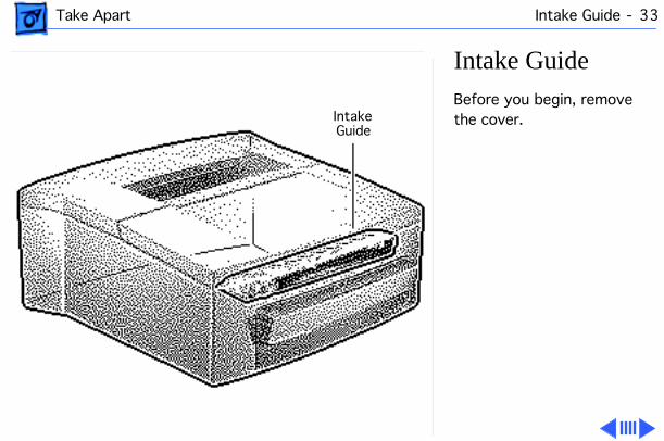
Intake Guide
Before you begin, remove the cover.Intake
Guide
Take Apart Intake Guide - 34
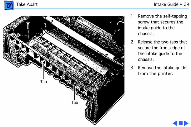
1 Remove the self-tapping screw that secures the intake guide to the chassis.
2 Release the two tabs that secure the front edge of the intake guide to the chassis.
3 Remove the intake guide from the printer.
Tab
Tab
Take Apart Lock Guide - 35
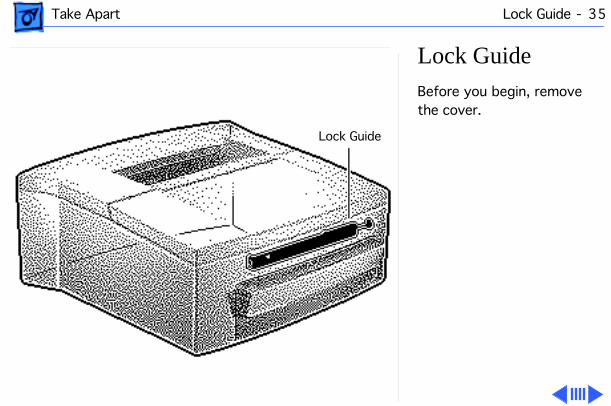
Lock Guide
Before you begin, remove the cover.
Lock Guide
Take Apart Lock Guide - 36
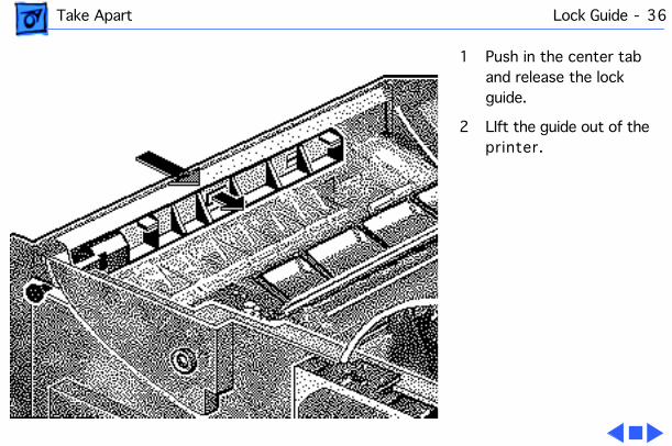
1 Push in the center tab and release the lock guide.
2 LIft the guide out of the printer.
Take Apart Transfer Roller Assembly - 37
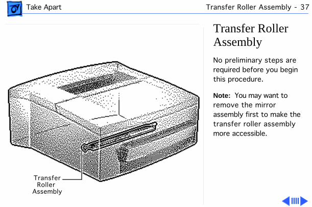
Transfer Roller Assembly
No preliminary steps are required before you begin this procedure.
Note:
You may want to remove the mirror assembly first to make the transfer roller assembly more accessible.
TransferRoller
Assembly
Take Apart Transfer Roller Assembly - 38
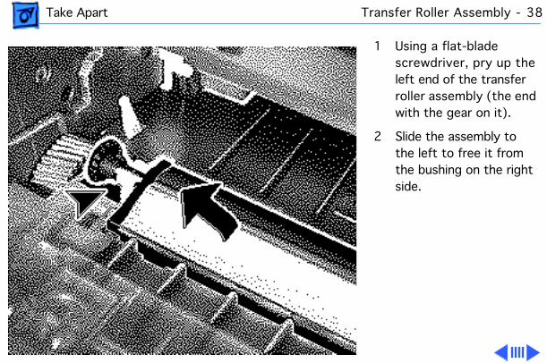
1 Using a flat-blade screwdriver, pry up the left end of the transfer roller assembly (the end with the gear on it).
2 Slide the assembly to the left to free it from the bushing on the right side.
Take Apart Transfer Roller Assembly - 39
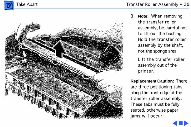
3
Note:
When removing the transfer roller assembly, be careful not to lift out the bushing. Hold the transfer roller assembly by the shaft, not the sponge area.
Lift the transfer roller assembly out of the printer.
Replacement Caution:
There are three positioning tabs along the front edge of the transfer roller assembly. These tabs must be fully seated, otherwise paper jams will occur.
Take Apart Transfer Mount Assemblies - 40
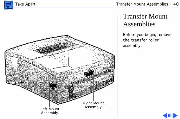
Transfer Mount Assemblies
Before you begin, remove the transfer roller assembly.
Left MountAssembly
Right MountAssembly
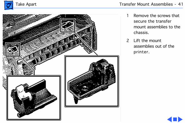
Take Apart Transfer Mount Assemblies - 41
1 Remove the screws that secure the transfer mount assemblies to the chassis.
2 Lift the mount assemblies out of the printer.
Take Apart I/O Board - 42
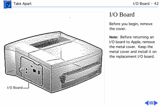
I/O Board
Before you begin, remove the cover.
Note:
Before returning an I/O board to Apple, remove the metal cover. Keep the metal cover and install it on the replacement I/O board.
I/O Board
Take Apart I/O Board - 43
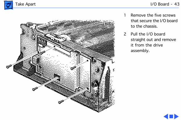
1 Remove the five screws that secure the I/O board to the chassis.
2 Pull the I/O board straight out and remove it from the drive assembly.
Take Apart Motor Assembly - 44
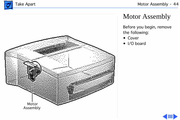
Motor Assembly
Before you begin, remove the following:• Cover• I/O board
MotorAssembly
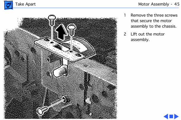
Take Apart Motor Assembly - 45
1 Remove the three screws that secure the motor assembly to the chassis.
2 LIft out the motor assembly.
Take Apart Controller Assembly - 46
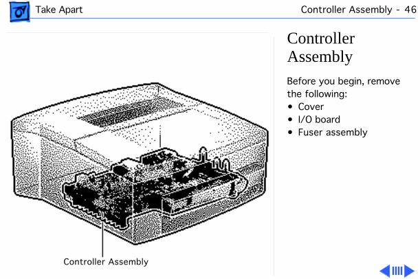
Controller Assembly
Before you begin, remove the following:• Cover• I/O board• Fuser assembly
Controller Assembly
Take Apart Controller Assembly - 47
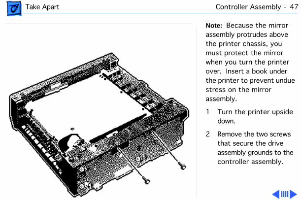
Note:
Because the mirror assembly protrudes above the printer chassis, you must protect the mirror when you turn the printer over. Insert a book under the printer to prevent undue stress on the mirror assembly.
1 Turn the printer upside down.
2 Remove the two screws that secure the drive assembly grounds to the controller assembly.
Take Apart Controller Assembly - 48
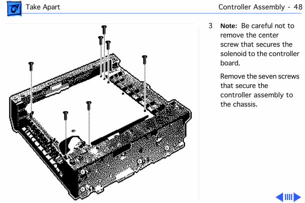
3
Note:
Be careful not to remove the center screw that secures the solenoid to the controller board.
Remove the seven screws that secure the controller assembly to the chassis.
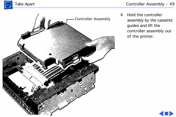
Take Apart Controller Assembly - 49
4 Hold the controller assembly by the cassette guides and lift the controller assembly out of the printer.
Controller Assembly
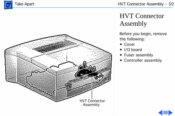
Take Apart HVT Connector Assembly - 50
HVT Connector Assembly
Before you begin, remove the following:• Cover• I/O board• Fuser assembly• Controller assembly
HVT ConnectorAssembly
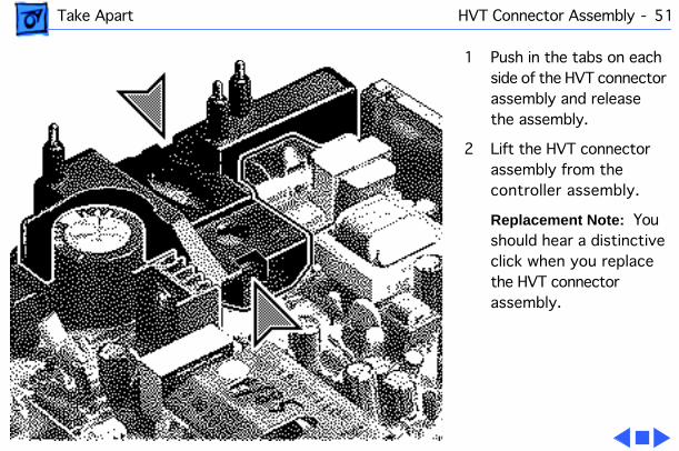
Take Apart HVT Connector Assembly - 51
1 Push in the tabs on each side of the HVT connector assembly and release the assembly.
2 Lift the HVT connector assembly from the controller assembly.
Replacement Note: You should hear a distinctive click when you replace the HVT connector assembly.
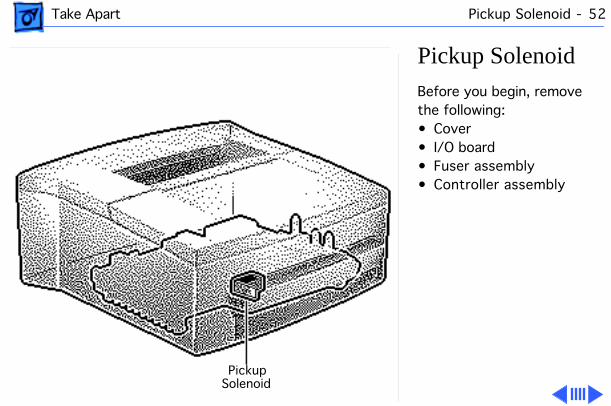
Take Apart Pickup Solenoid - 52
Pickup SolenoidBefore you begin, remove the following:• Cover• I/O board• Fuser assembly• Controller assembly
PickupSolenoid
Take Apart Pickup Solenoid - 53
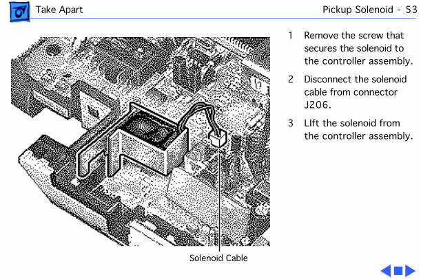
1 Remove the screw that secures the solenoid to the controller assembly.
2 Disconnect the solenoid cable from connector J206.
3 LIft the solenoid from the controller assembly.
Solenoid Cable

Take Apart Drive Assembly - 54
Drive AssemblyBefore you begin, remove the following:• Cover• I/O board
DriveAssembly
Take Apart Drive Assembly - 55
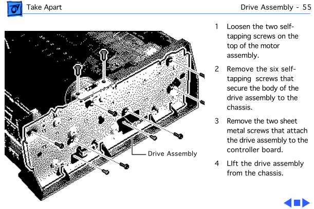
1 Loosen the two self-tapping screws on the top of the motor assembly.
2 Remove the six self-tapping screws that secure the body of the drive assembly to the chassis.
3 Remove the two sheet metal screws that attach the drive assembly to the controller board.
4 LIft the drive assembly from the chassis.
Drive Assembly
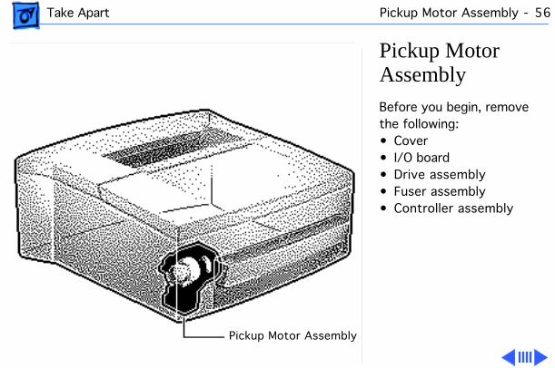
Take Apart Pickup Motor Assembly - 56
Pickup Motor AssemblyBefore you begin, remove the following:• Cover• I/O board• Drive assembly• Fuser assembly• Controller assembly
Pickup Motor Assembly
Take Apart Pickup Motor Assembly - 57
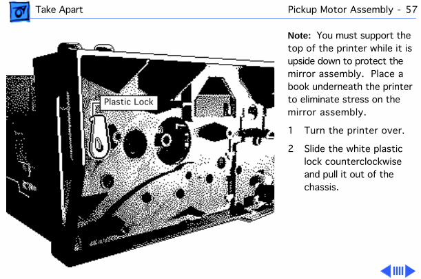
Note: You must support the top of the printer while it is upside down to protect the mirror assembly. Place a book underneath the printer to eliminate stress on the mirror assembly.
1 Turn the printer over.
2 Slide the white plastic lock counterclockwise and pull it out of the chassis.
Plastic Lock
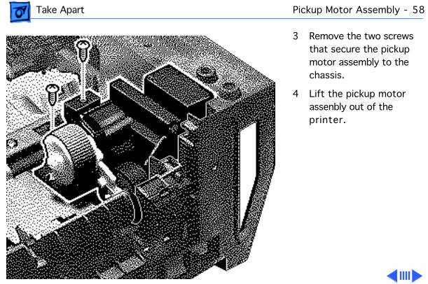
Take Apart Pickup Motor Assembly - 58
3 Remove the two screws that secure the pickup motor assembly to the chassis.
4 Lift the pickup motor assenbly out of the printer.
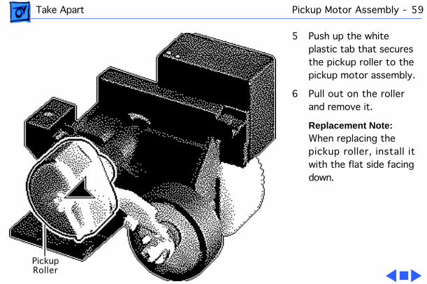
Take Apart Pickup Motor Assembly - 59
5 Push up the white plastic tab that secures the pickup roller to the pickup motor assembly.
6 Pull out on the roller and remove it.
Replacement Note: When replacing the pickup roller, install it with the flat side facing down.
PickupRoller
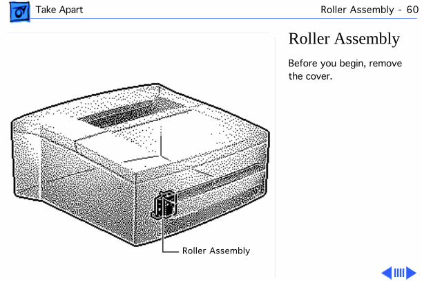
Take Apart Roller Assembly - 60
Roller Assembly Before you begin, remove the cover.
Roller Assembly
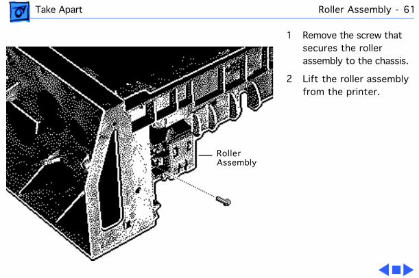
Take Apart Roller Assembly - 61
1 Remove the screw that secures the roller assembly to the chassis.
2 Lift the roller assembly from the printer.
RollerAssembly
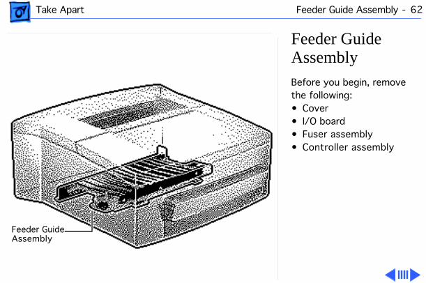
Take Apart Feeder Guide Assembly - 62
Feeder Guide AssemblyBefore you begin, remove the following:• Cover• I/O board• Fuser assembly• Controller assembly
Feeder GuideAssembly
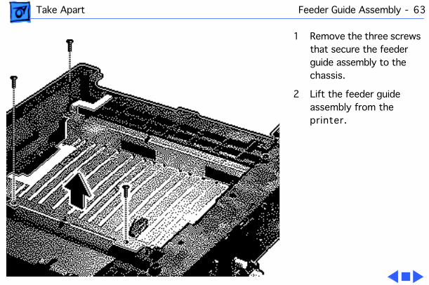
Take Apart Feeder Guide Assembly - 63
1 Remove the three screws that secure the feeder guide assembly to the chassis.
2 Lift the feeder guide assembly from the printer.
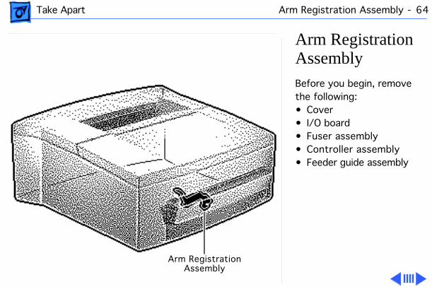
Take Apart Arm Registration Assembly - 64
Arm Registration AssemblyBefore you begin, remove the following:• Cover• I/O board• Fuser assembly• Controller assembly• Feeder guide assembly
Arm RegistrationAssembly
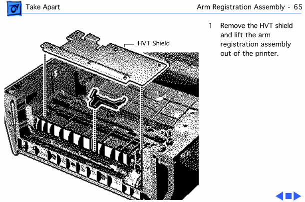
Take Apart Arm Registration Assembly - 65
1 Remove the HVT shield and lift the arm registration assembly out of the printer.
HVT Shield
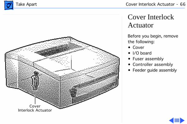
Take Apart Cover Interlock Actuator - 66
Cover Interlock ActuatorBefore you begin, remove the following:• Cover• I/O board• Fuser assembly• Controller assembly• Feeder guide assembly
CoverInterlock Actuator
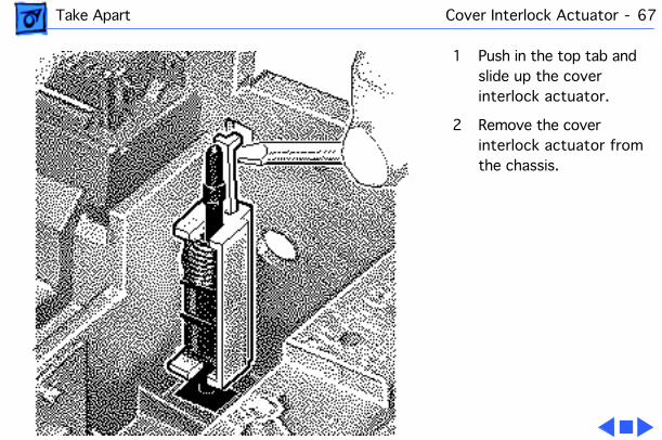
Take Apart Cover Interlock Actuator - 67
1 Push in the top tab and slide up the cover interlock actuator.
2 Remove the cover interlock actuator from the chassis.
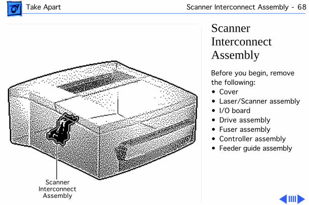
Take Apart Scanner Interconnect Assembly - 68
Scanner Interconnect AssemblyBefore you begin, remove the following:• Cover• Laser/Scanner assembly• I/O board• Drive assembly• Fuser assembly• Controller assembly• Feeder guide assembly
ScannerInterconnect
Assembly
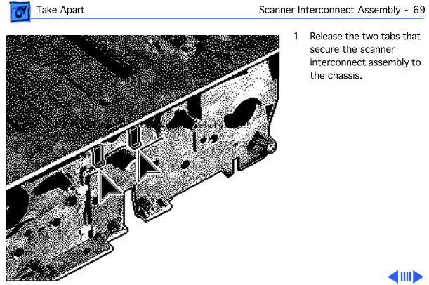
Take Apart Scanner Interconnect Assembly - 69
1 Release the two tabs that secure the scanner interconnect assembly to the chassis.
Take Apart Scanner Interconnect Assembly - 70
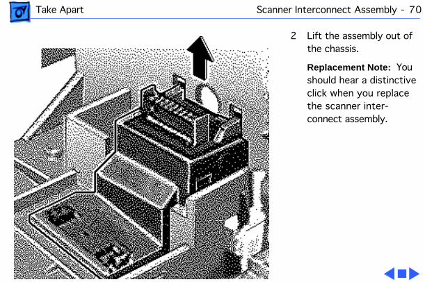
2 Lift the assembly out of the chassis.
Replacement Note: You should hear a distinctive click when you replace the scanner inter-connect assembly.
Take Apart Chassis - 71
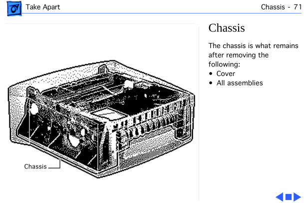
ChassisThe chassis is what remains after removing the following:• Cover• All assemblies
Chassis
Service Source
K
Upgrades
PLW 300 & LW4/600 PS
Upgrades LW 4/600 Memory Upgrade - 1
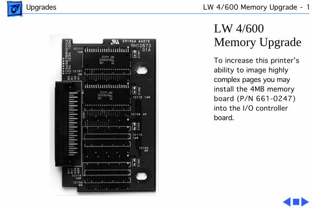
LW 4/600 Memory Upgrade
To increase this printer’s ability to image highly complex pages you may install the 4MB memory board (P/N 661-0247) into the I/O controller board.
Service Source
K
Additional Procedures
PLW 300 & LW 4/600 PS
Additional Procedures Mirror Assembly Maintenance - 1
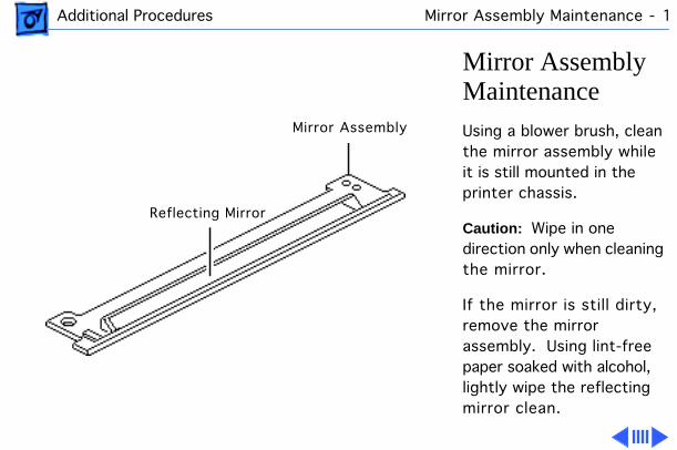
Mirror Assembly Maintenance
Using a blower brush, clean the mirror assembly while it is still mounted in the printer chassis.
Caution:
Wipe in one direction only when cleaning the mirror.
If the mirror is still dirty, remove the mirror assembly. Using lint-free paper soaked with alcohol, lightly wipe the reflecting mirror clean.
Mirror Assembly
Reflecting Mirror

Additional Procedures Mirror Assembly Maintenance - 2
Refer to the Adjustments chapter for information on how to adjust the mirror after reinstalling it.
Additional Procedures Transfer Roller Maintenance - 3
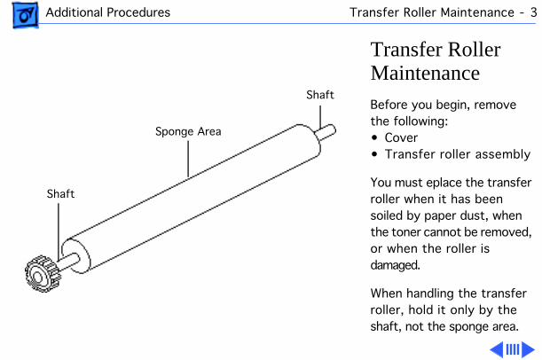
Transfer Roller Maintenance
Before you begin, remove the following:• Cover• Transfer roller assembly
You must eplace the transfer roller when it has been soiled by paper dust, when the toner cannot be removed, or when the roller is damaged.
When handling the transfer roller, hold it only by the shaft, not the sponge area.
Sponge Area
Shaft
Shaft
Additional Procedures Transfer Roller Maintenance - 4
If the transfer roller becomes dirty, clean it using dry, lint-free paper, which should produce virtually no paper dust.
Caution:
Use dry paper only to clean the transfer roller. Never use solvents.
Service Source
K
Adjustments
PLW 300 & LW 4/600 PS
Adjustments Mirror Assembly - 1
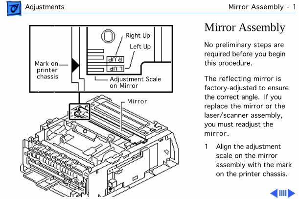
Mirror Assembly
No preliminary steps are required before you begin this procedure.
The reflecting mirror is factory-adjusted to ensure the correct angle. If you replace the mirror or the laser/scanner assembly, you must readjust the mirror.
1 Align the adjustment scale on the mirror assembly with the mark on the printer chassis.
Mark onprinterchassis
Right Up
Left Up
Adjustment Scaleon Mirror
Mirror
Adjustments Mirror Assembly - 2
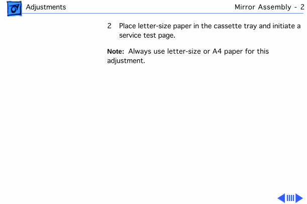
2 Place letter-size paper in the cassette tray and initiate a service test page.
Note:
Always use letter-size or A4 paper for this adjustment.
Adjustments Mirror Assembly - 3
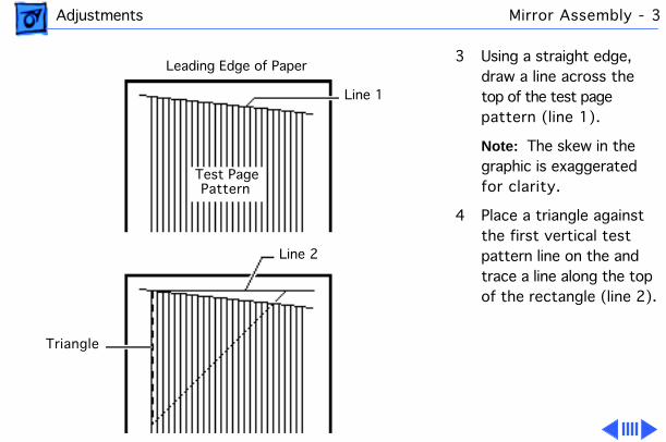
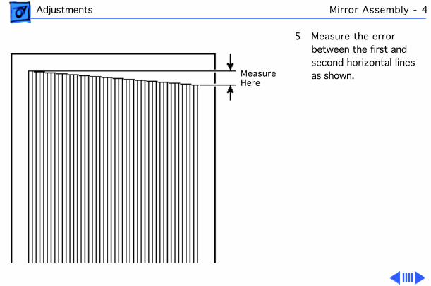
3 Using a straight edge, draw a line across the top of the test page pattern (line 1).
Note:
The skew in the graphic is exaggerated for clarity.
4 Place a triangle against the first vertical test pattern line on the and trace a line along the top of the rectangle (line 2).
Leading Edge of Paper
Line 1
Line 2
Triangle
Test PagePattern
Adjustments Mirror Assembly - 4
5 Measure the error between the first and second horizontal lines as shown. Measure
Here
Adjustments Mirror Assembly - 5
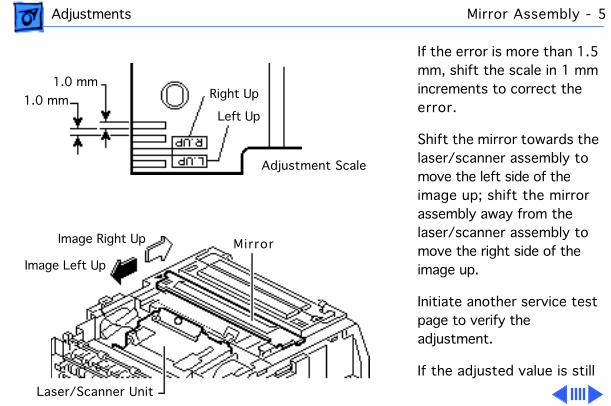
If the error is more than 1.5 mm, shift the scale in 1 mm increments to correct the error.
Shift the mirror towards the laser/scanner assembly to move the left side of the image up; shift the mirror assembly away from the laser/scanner assembly to move the right side of the image up.
Initiate another service test page to verify the adjustment.
If the adjusted value is still
Adjustment Scale
1.0 mm
1.0 mm Right Up
Left Up
MirrorImage Right Up
Image Left Up
Laser/Scanner Unit
Adjustments Mirror Assembly - 6
incorrect, repeat the adjustment procedure until the error is less than 1.5 mm.
Adjustments Registration Adjustment - 7
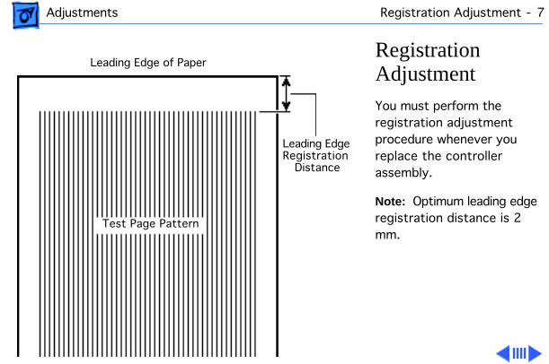
Registration Adjustment
You must perform the registration adjustment procedure whenever you replace the controller assembly.
Note:
Optimum leading edge registration distance is 2 mm.
Leading Edge
Leading Edge of Paper
Test Page Pattern
RegistrationDistance
Adjustments Registration Adjustment - 8
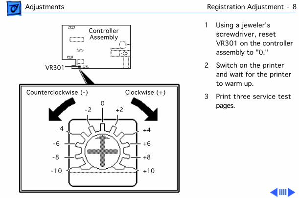
1 Using a jeweler's screwdriver, reset VR301 on the controller assembly to "0."
2 Switch on the printer and wait for the printer to warm up.
3 Print three service test pages.
ControllerAssembly
VR301
Counterclockwise (-) Clockwise (+)
0-2
-4
-6
-8
-10
+2
+4
+6
+8
+10
Adjustments Registration Adjustment - 9
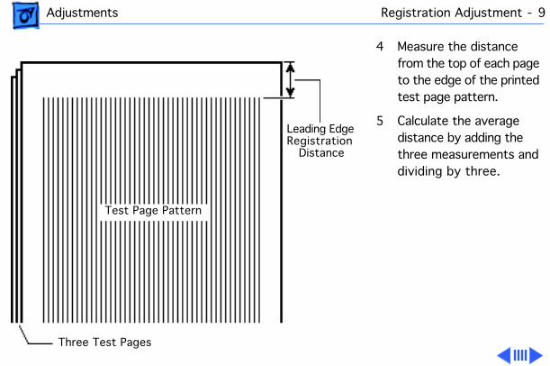
4 Measure the distance from the top of each page to the edge of the printed test page pattern.
5 Calculate the average distance by adding the three measurements and dividing by three.
Leading EdgeRegistration
Distance
Test Page Pattern
Three Test Pages
Adjustments Registration Adjustment - 10
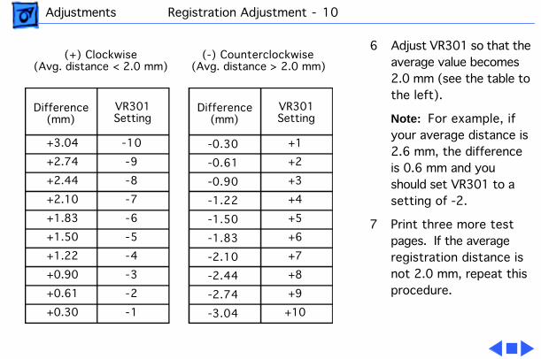
6 Adjust VR301 so that the average value becomes 2.0 mm (see the table to the left).
Note:
For example, if your average distance is 2.6 mm, the difference is 0.6 mm and you should set VR301 to a setting of -2.
7 Print three more test pages. If the average registration distance is not 2.0 mm, repeat this procedure.
(+) Clockwise(Avg. distance < 2.0 mm)
(-) Counterclockwise(Avg. distance > 2.0 mm)
Difference(mm)
+3.04
+2.74
+2.44
+2.10
+1.83
+1.50
+1.22
+0.90
+0.61
+0.30
VR301Setting
-10
-9
-8
-7
-6
-5
-4
-3
-2
-1
Difference(mm)
VR301Setting
-0.30
-0.61
-0.90
-1.22
-1.50
-1.83
-2.10
-2.44
-2.74
-3.04
+1
+2
+3
+4
+5
+6
+7
+8
+9
+10
Service Source
K
Exploded View
PLW 300 & LW 4/600 PS
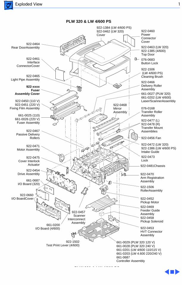
Exploded View 1
922-0464Rear DoorAssembly
922-0460PowerConnectorCover
922-0463 (LW 320)922-1385 (4/600)Top Door
076-0683Button Lock
922-1506 (LW 4/600 PS)Cleaning Brush
922-1384 (LW 4/600 PS)922-0462 (LW 320)Cover
922-0461Interface
ConnectorCover
922-0465Light Pipe Assembly
922-0450 (110 V)922-0451 (220 V)
Fixing Film Assembly
661-0027 (PLW 320)661-0202 (LW 4/600)Laser/ScannerAssembly
922-0466Delivery RollerAssembly
922-0471Motor Assembly
922-0467Passive Delivery
Rollers
922-0475Cover Interlock
Actuator
922-0454Drive Assembly
661-0687I/O Board (320)
922-0660I/O BoardCover
922-0468MirrorAssembly
076-0168Transfer RollerAssembly
922-0477 (L)922-0478 (R)Transfer MountAssemblies
922-0472 (LW 320)922-1386 (LW 4/600 PS)Intake Guide
922-0473Lock
922-0456 Fan
922-0470Arm RegistrationAssembly
922-1506 RollerAssembly
922-0452Pickup Motor
661-0029 (PLW 320 120 V)661-0028 (PLW 320 240 V)661-0201 (LW 4/600 110/115 V)661-0203 (LW 4.600 220/240 V)661-0687Controller Assembly
922-0469Feeder GuideAssembly922-0458Pickup Solenoid
922-0453HVT ConnectorAssembly
922-0457Scanner
Interconnect Assembly
922-0481Chassis
922-xxxxFuser
Assembly Cover
661-0025 (110)661-0026 (220 V)
Fuser Assembly
661-0200I/O Board (4/600)
922-1502Test Print Lever (4/600)
PLW 320 & LW 4/600 PS
PLW 320 & LW 4/600 PS