pluto gateway siemens s7 integration manual - abb … gateway siemens s7 integration manual . ......
TRANSCRIPT
English v1B 2TLC172013M0201_B
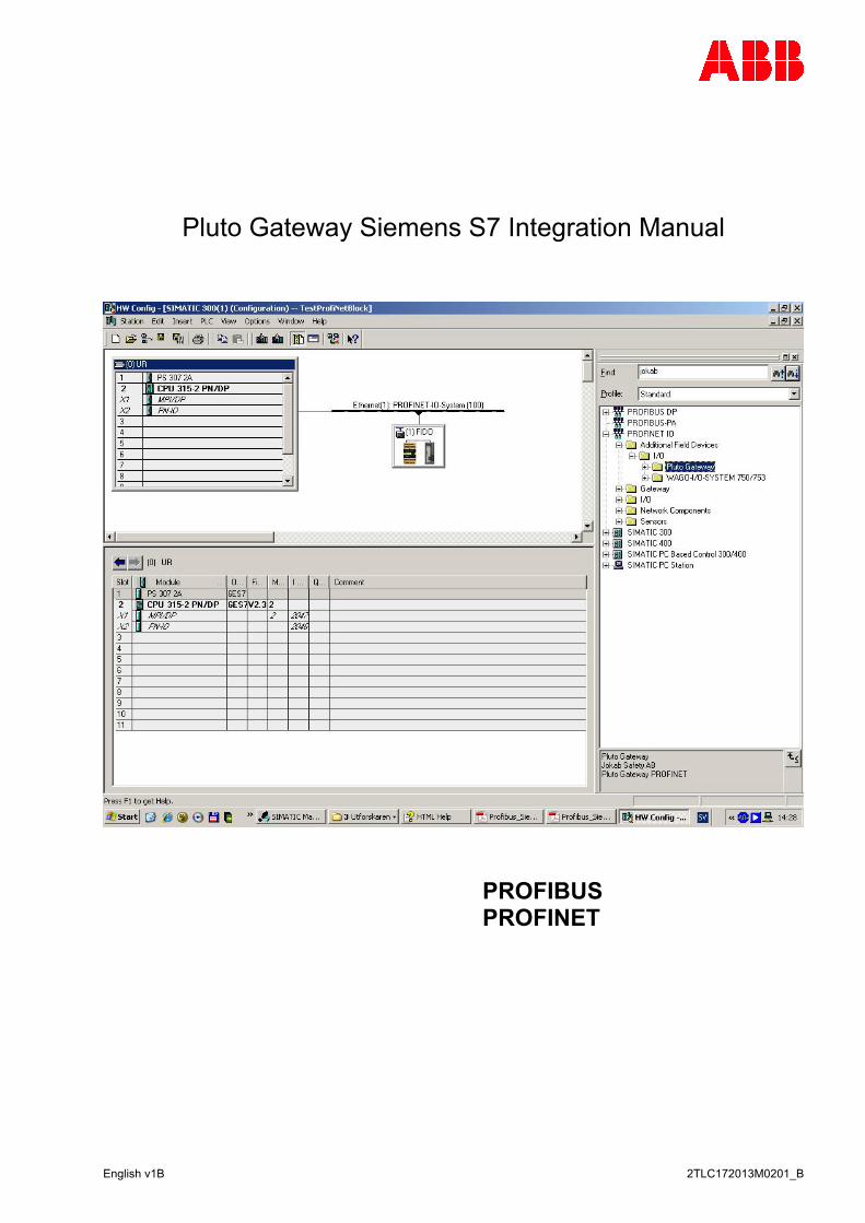
Pluto Gateway Siemens S7 Integration Manual
PROFIBUS PROFINET

2 2TLC172013M0201_B
Revision history:
Version Date Change 1A 2010-11-30 First release
Merging “Profinet_Siemens_S7_Manual” and “Profibus_Siemens_S7_Manual_v3A” into one (this) manual. Changed to ABB style
1B 2011-12-20 Changed title
Reference:
REF Document A Pluto Gateway User Manual (PlutoGatewayManual-Eng-xx)
Table of contents: 1 General..............................................................................................................................................4 2 Hardware...........................................................................................................................................5 2.1 Casing ...............................................................................................................................................5 2.2 Pluto bus ...........................................................................................................................................7 2.2.1 Connecting the Plutobus...................................................................................................................7 2.2.2 Baudrate detection ............................................................................................................................7 2.2.3 Status LED for Plutobus....................................................................................................................7 2.2.4 Gateway Address Plutobus settings .................................................................................................8 2.3 Profibus .............................................................................................................................................9 2.3.1 Connecting the Profibus....................................................................................................................9 2.3.2 Baudrate Profibus ...........................................................................................................................10 2.3.3 Status LED for Profibus...................................................................................................................10 2.3.4 Gateway Address Profibus setting..................................................................................................11 3 Setup in Pluto Manager...................................................................................................................12 3.1 Selecting the function library ...........................................................................................................12 3.2 Transmitting from Pluto to Siemens PLC........................................................................................13 3.2.1 Transmit global data from Pluto ......................................................................................................13 3.2.2 Transmit other data from the Pluto .................................................................................................14 3.3 Transmitting from the Siemens PLC to the Pluto............................................................................18 3.3.1 Setup External Communication in the PlutoManager .....................................................................18 3.3.2 Receive Data in the Pluto................................................................................................................19 4 Setup in Simatic Manager ...............................................................................................................21 4.1 Setup in the HW Config...................................................................................................................21 4.1.1 GSD-file selection and installation ..................................................................................................21 4.1.2 Gateway selection and connection .................................................................................................22 4.2 Function block library ......................................................................................................................26 4.2.1 Installation .......................................................................................................................................26 4.2.2 Use..................................................................................................................................................26 5 PROFIBUS function block description ............................................................................................27 5.1 Function block - request/respond of local data (write/read)............................................................27 5.2 Function block - Global data from Pluto (read) ...............................................................................28 5.3 Function block - Data to Pluto (write)..............................................................................................29 5.4 Function block – Additional data – USER A (read).........................................................................30 5.5 Function block – Additional data – USER B (read).........................................................................31 5.6 Function block – Additional data – USER C (read).........................................................................32 5.7 Function block – Additional data – Error code (read) .....................................................................33 5.8 Function block – Additional data – B46 I20-I47 (read)....................................................................34 5.9 Function block – Additional data – ASi 16-31 safe (read)...............................................................35
3 2TLC172013M0201_B
5.10 Function block – Additional data – ASi 1-3 non safe (read)............................................................36 5.11 Function block – Additional data – ASi 4-7 non safe (read)............................................................37 5.12 Function block – Additional data – ASi 8-11 non safe (read)..........................................................38 5.13 Function block – Additional data – ASi 12-15 non safe (read)........................................................39 5.14 Function block – Additional data – ASi 16-19 non safe (read)........................................................40 5.15 Function block – Additional data – ASi 20-23 non safe (read)........................................................41 5.16 Function block – Additional data – ASi 24-27 non safe (read)........................................................42 5.17 Function block – Additional data – ASi 28-31 non safe (read)........................................................43 6 PROFINET function block description ............................................................................................44 6.1 General............................................................................................................................................44 6.2 Function block - request/respond of local data (write/read)............................................................45 6.3 Function block - Global data from Pluto (read) ...............................................................................46 6.4 Function block - Data to Pluto (write)..............................................................................................47 6.5 Function block – Additional data – USER A bit (read) ....................................................................48 6.6 Function block – Additional Data – USER A Int (read) ...................................................................49 6.7 Function block – Additional data – USER B (read).........................................................................50 6.8 Function block – Additional data – USER C (read).........................................................................51 6.9 Function block – Additional data – Error code (read) .....................................................................52 6.10 Function block – Additional data – B46 I20-I47 (read)....................................................................53 6.11 Function block – Additional data – ASi 16-31 safe (read)...............................................................54 6.12 Function block – Additional data – ASi 1-3 non safe (read)............................................................55 6.13 Function block – Additional data – ASi 4-7 non safe (read)............................................................56 6.14 Function block – Additional data – ASi 8-11 non safe (read)..........................................................57 6.15 Function block – Additional data – ASi 12-15 non safe (read)........................................................58 6.16 Function block – Additional data – ASi 16-19 non safe (read)........................................................59 6.17 Function block – Additional data – ASi 20-23 non safe (read)........................................................60 6.18 Function block – Additional data – ASi 24-27 non safe (read)........................................................61 6.19 Function block – Additional data – ASi 28-31 non safe (read)........................................................62
4 2TLC172013M0201_B
1 General The PROFIBUS Gateway GATE-P1/P2 is a unit used to transfer data between PROFIBUS and Plutobus. The Ethernet Gateway GATE-E1/E2 is a unit used to transfer data between PROFINET and Plutobus. Communication both ways is possible. This document describes how to setup and work with the Pluto gateway Gate-P1/P2 in Pluto Manager and Siemens Step7. It also brings up how to use a number of sample function blocks for the Siemens S7 PLC family for complete communication back and forth between a Pluto unit and a Siemens PLC, through the gateway. All functions are samples and are to be used “as is”. Every instance of the Function Blocks needs to be connected to an instance data block, see the Siemens Step 7 manual.
2 Hardware
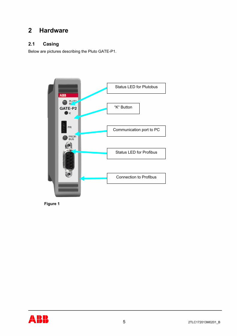
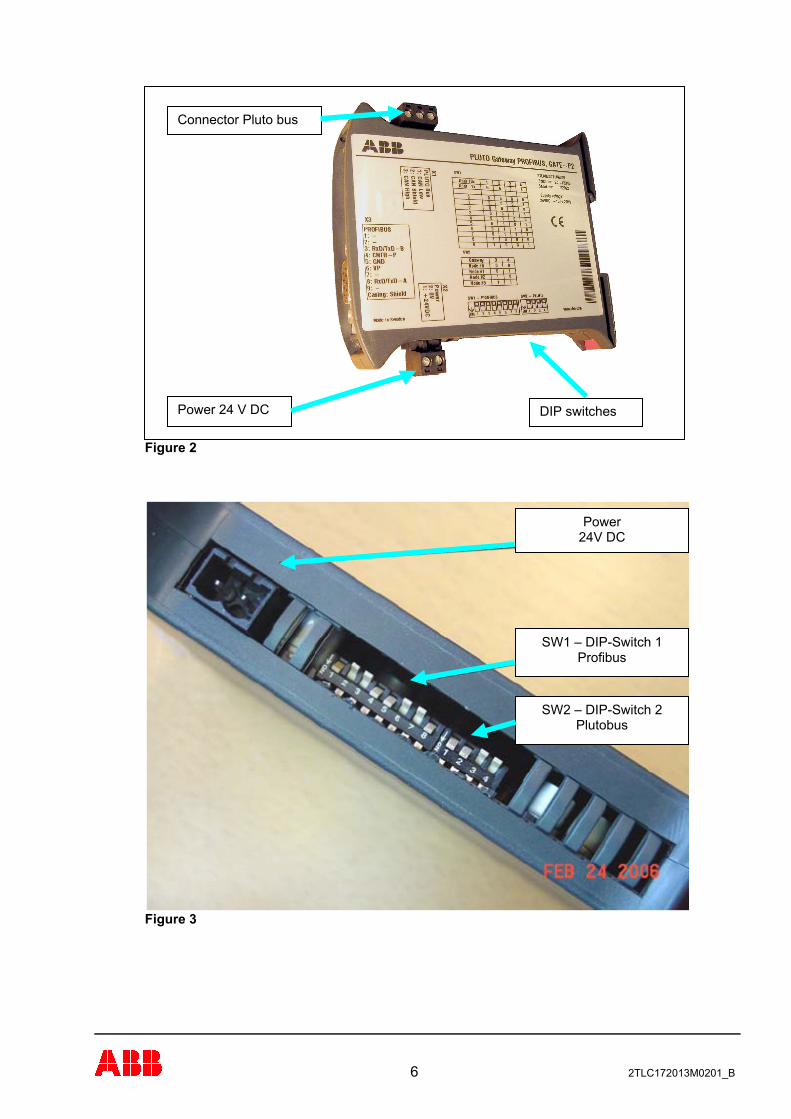
2.1 Casing Below are pictures describing the Pluto GATE-P1.
5 2TLC172013M0201_B
Figure 1
“K“ Button
Status LED for Plutobus
Communication port to PC
Status LED for Profibus
Connection to Profibus
6 2TLC172013M0201_B
Figure 2
Figure 3
Power 24V DC
SW1 – DIP-Switch 1 Profibus
SW2 – DIP-Switch 2 Plutobus
Connector Pluto bus
Power 24 V DC DIP switches
7 2TLC172013M0201_B
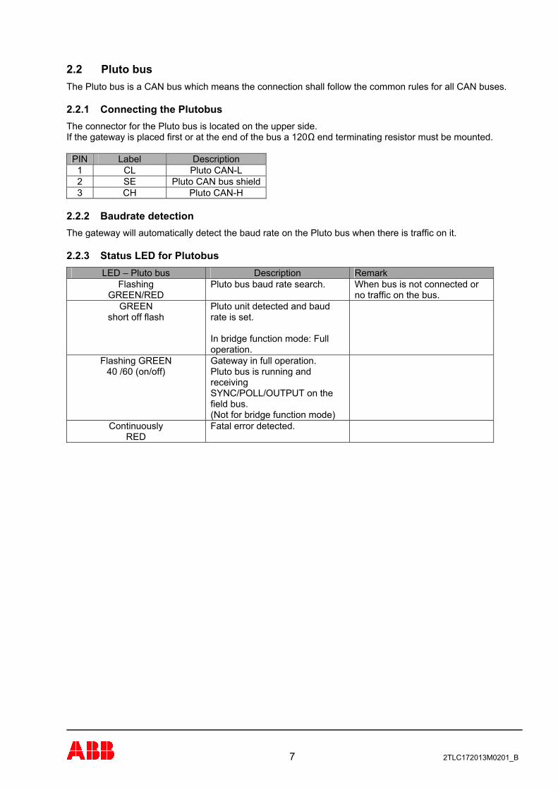
2.2 Pluto bus The Pluto bus is a CAN bus which means the connection shall follow the common rules for all CAN buses.
2.2.1 Connecting the Plutobus The connector for the Pluto bus is located on the upper side. If the gateway is placed first or at the end of the bus a 120Ω end terminating resistor must be mounted.
PIN Label Description 1 CL Pluto CAN-L 2 SE Pluto CAN bus shield 3 CH Pluto CAN-H
2.2.2 Baudrate detection The gateway will automatically detect the baud rate on the Pluto bus when there is traffic on it.
2.2.3 Status LED for Plutobus LED – Pluto bus Description Remark
Flashing GREEN/RED
Pluto bus baud rate search. When bus is not connected or no traffic on the bus.
GREEN short off flash
Pluto unit detected and baud rate is set. In bridge function mode: Full operation.
Flashing GREEN 40 /60 (on/off)
Gateway in full operation. Pluto bus is running and receiving SYNC/POLL/OUTPUT on the field bus. (Not for bridge function mode)
Continuously RED
Fatal error detected.
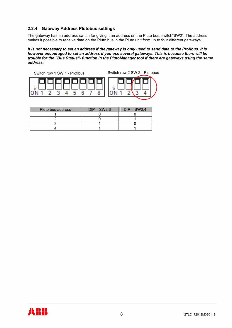
2.2.4 Gateway Address Plutobus settings The gateway has an address switch for giving it an address on the Pluto bus, switch”SW2”. The address makes it possible to receive data on the Pluto bus in the Pluto unit from up to four different gateways. It is not necessary to set an address if the gateway is only used to send data to the Profibus. It is however encouraged to set an address if you use several gateways. This is because there will be trouble for the ”Bus Status“- function in the PlutoManager tool if there are gateways using the same address.
Switch row 2 SW 2 - Plutobus Switch row 1 SW 1 - Profibus
Pluto bus address DIP – SW2.3 DIP – SW2.4 1 0 0 2 0 1 3 1 0 4 1 1
8 2TLC172013M0201_B
2.3 Profibus The Profibus is implemented in the Gateway as a DP Slave using the DP-V0 protocol. The DP-V0 protocol is fully compatible with the DPV1 and DPV2 protocols.
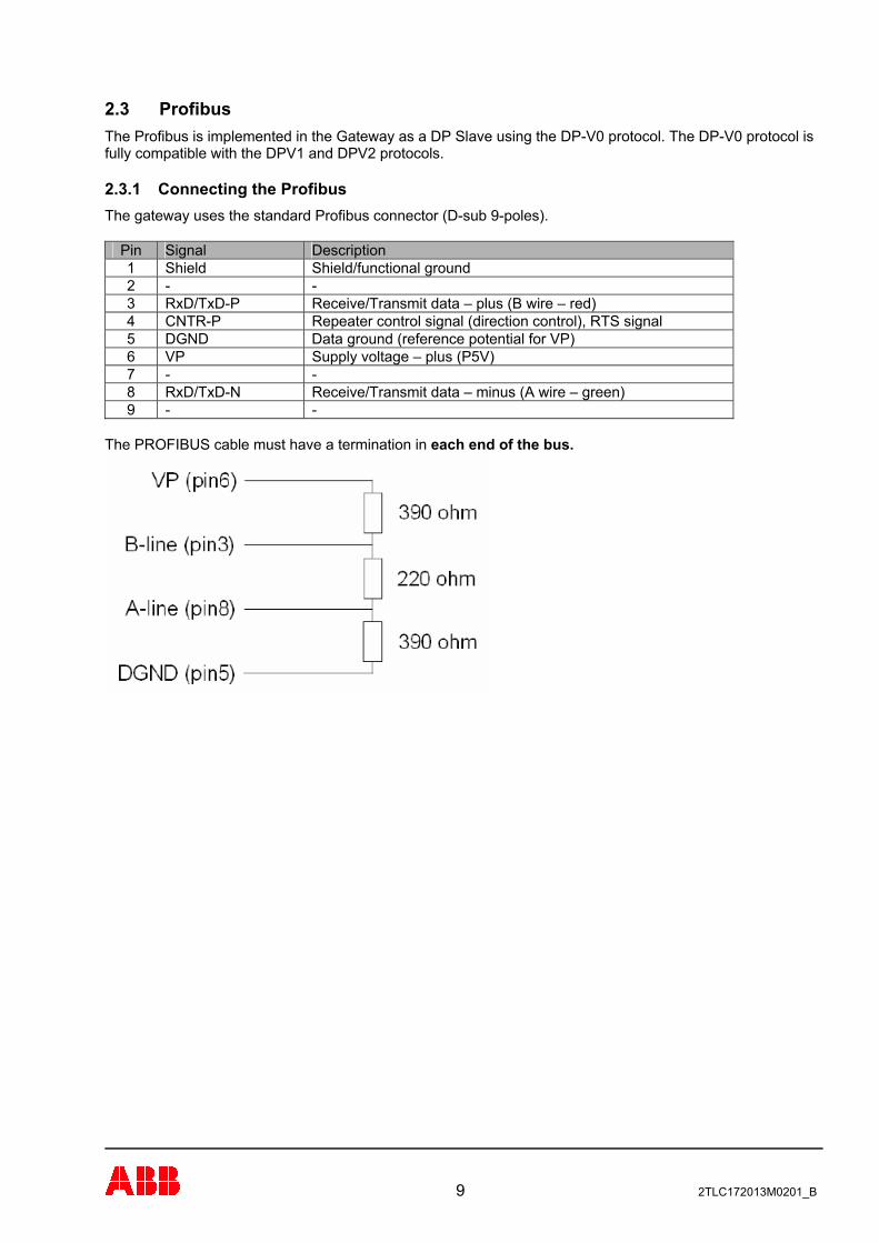
2.3.1 Connecting the Profibus The gateway uses the standard Profibus connector (D-sub 9-poles).
Pin Signal Description 1 Shield Shield/functional ground 2 - - 3 RxD/TxD-P Receive/Transmit data – plus (B wire – red) 4 CNTR-P Repeater control signal (direction control), RTS signal 5 DGND Data ground (reference potential for VP) 6 VP Supply voltage – plus (P5V) 7 - - 8 RxD/TxD-N Receive/Transmit data – minus (A wire – green) 9 - -
The PROFIBUS cable must have a termination in each end of the bus.
9 2TLC172013M0201_B
10 2TLC172013M0201_B
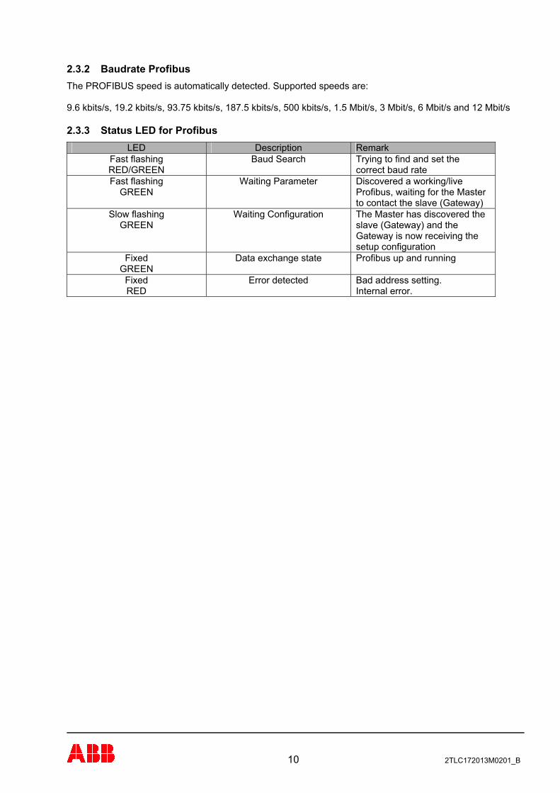
2.3.2 Baudrate Profibus The PROFIBUS speed is automatically detected. Supported speeds are: 9.6 kbits/s, 19.2 kbits/s, 93.75 kbits/s, 187.5 kbits/s, 500 kbits/s, 1.5 Mbit/s, 3 Mbit/s, 6 Mbit/s and 12 Mbit/s
2.3.3 Status LED for Profibus LED Description Remark
Fast flashing RED/GREEN
Baud Search Trying to find and set the correct baud rate
Fast flashing GREEN
Waiting Parameter Discovered a working/live Profibus, waiting for the Master to contact the slave (Gateway)
Slow flashing GREEN
Waiting Configuration The Master has discovered the slave (Gateway) and the Gateway is now receiving the setup configuration
Fixed GREEN
Data exchange state Profibus up and running
Fixed RED
Error detected Bad address setting. Internal error.
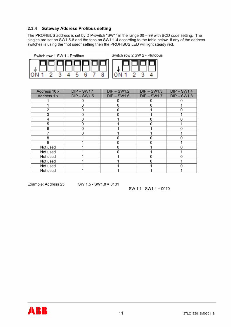
2.3.4 Gateway Address Profibus setting The PROFIBUS address is set by DIP-switch “SW1” in the range 00 – 99 with BCD code setting. The singles are set on SW1:5-8 and the tens on SW1:1-4 according to the table below. If any of the address switches is using the “not used” setting then the PROFIBUS LED will light steady red.
Switch row 2 SW 2 - Plutobus Switch row 1 SW 1 - Profibus
Address 10 x DIP – SW1.1 DIP – SW1.2 DIP – SW1.3 DIP – SW1.4 Address 1 x DIP – SW1.5 DIP – SW1.6 DIP – SW1.7 DIP – SW1.8
1 0 0 0 0 1 0 0 0 1 2 0 0 1 0 3 0 0 1 1 4 0 1 0 0 5 0 1 0 1 6 0 1 1 0 7 0 1 1 1 8 1 0 0 0 9 1 0 0 1
Not used 1 0 1 0 Not used 1 0 1 1 Not used 1 1 0 0 Not used 1 1 0 1 Not used 1 1 1 0 Not used 1 1 1 1
Example: Address 25 SW 1.5 - SW1.8 = 0101 SW 1.1 - SW1.4 = 0010
11 2TLC172013M0201_B
3 Setup in Pluto Manager All global data from the Pluto units (max. 32) connected to the Pluto bus is sent constantly, cyclically. In order to receive the global data in the Siemens PLC, no function library must be setup in Pluto Manager. In order to send data other than the global data, and to receive data from the Siemens PLC, a function library must be setup.
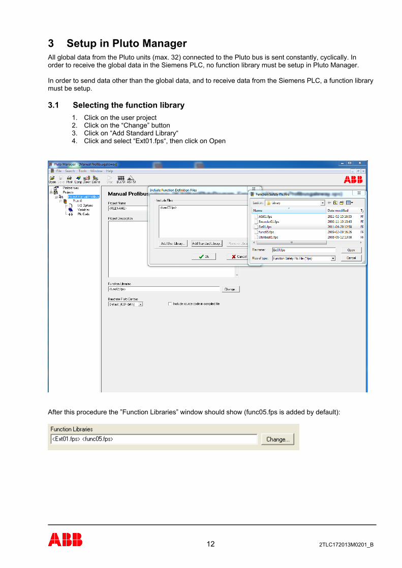
3.1 Selecting the function library 1. Click on the user project 2. Click on the “Change” button 3. Click on “Add Standard Library“ 4. Click and select “Ext01.fps“, then click on Open
After this procedure the ”Function Libraries” window should show (func05.fps is added by default):
12 2TLC172013M0201_B
13 2TLC172013M0201_B
3.2 Transmitting from Pluto to Siemens PLC This chapter describes how to transmit data on the Plutobus, through the gateway and onwards to the super ordinate system. Be careful to not cause unnecessary bus load on the Plutobus. A Pluto unit can only send four telegrams every PLC cycle. In a big network of Pluto units where every unit transmits every cycle the load on the bus will quickly become high. For examples on how to program see the “Pluto Gateway Manual”.
3.2.1 Transmit global data from Pluto The global data of each Pluto unit is constantly available on the Pluto CAN bus, with or without a connected gateway. The Pluto unit therefore does not need to be setup with any special transmission components for sending the global data. The global data consists of the following components: Global inputs: Ix.0 to Ix.7 Ix.10 to Ix.17 Global Memories: GMx.0 to GMx.11 Global outputs: Qx.0 to Qx.3 Where “x” is the number of the Pluto unit. Further setup in the PlutoManager for global data is not necessary! Note: In the Pluto B46-6 not all of the safety inputs are available as global data. The outputs Qx.4
and Qx.5 are not sent in the global data.
In order to send these extra inputs on the Pluto bus a special function (ToGateway_B46_I20_I47) from the “ext01.fps” library must be used. For Qx.4 and Qx.5 the function “ToGateway_User_B” could be used to send them as bits for example. The global data for Pluto-ASi varies from the other Pluto members. See the Pluto Gateway manual.
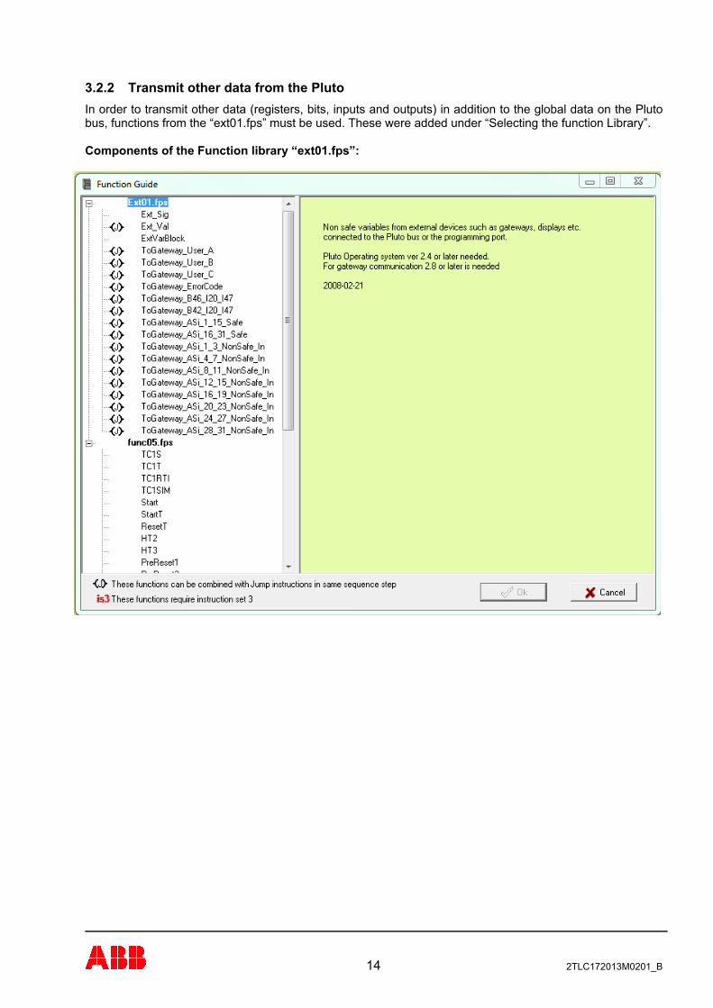
3.2.2 Transmit other data from the Pluto In order to transmit other data (registers, bits, inputs and outputs) in addition to the global data on the Pluto bus, functions from the “ext01.fps” must be used. These were added under “Selecting the function Library”. Components of the Function library “ext01.fps”:
14 2TLC172013M0201_B
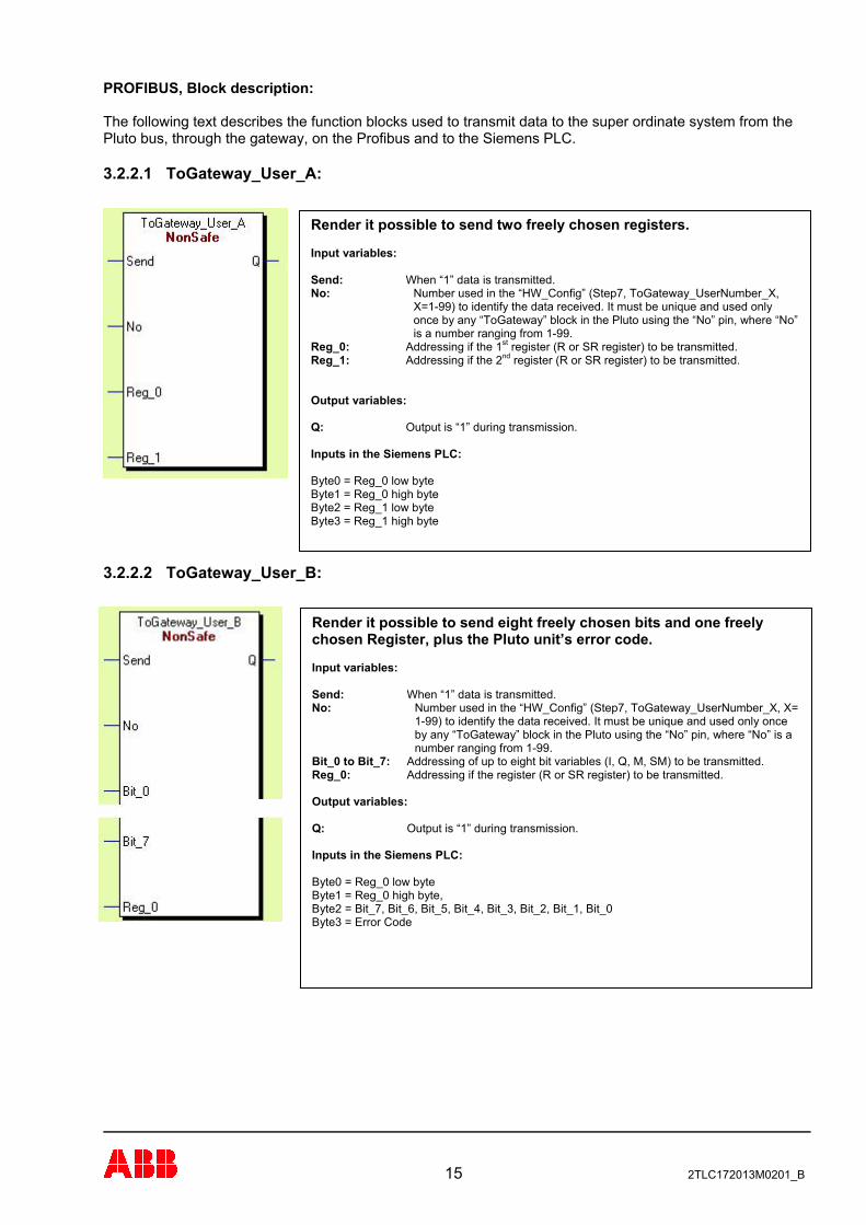
PROFIBUS, Block description: The following text describes the function blocks used to transmit data to the super ordinate system from the Pluto bus, through the gateway, on the Profibus and to the Siemens PLC.
3.2.2.1 ToGateway_User_A:
Render it possible to send two freely chosen registers.
Input variables:
Send: When “1” data is transmitted. No: Number used in the “HW_Config” (Step7, ToGateway_UserNumber_X,
X=1-99) to identify the data received. It must be unique and used only once by any “ToGateway” block in the Pluto using the “No” pin, where “No” is a number ranging from 1-99.
Reg_0: Addressing if the 1st register (R or SR register) to be transmitted. Reg_1: Addressing if the 2nd register (R or SR register) to be transmitted.
Output variables:
Q: Output is “1” during transmission.
Inputs in the Siemens PLC:
Byte0 = Reg_0 low byte Byte1 = Reg_0 high byte
Byte2 = Reg_1 low byte Byte3 = Reg_1 high byte
3.2.2.2 ToGateway_User_B:
Render it possible to send eight freely chosen bits and one freely chosen Register, plus the Pluto unit’s error code.
Input variables:
Send: When “1” data is transmitted. No: Number used in the “HW_Config” (Step7, ToGateway_UserNumber_X, X=
1-99) to identify the data received. It must be unique and used only once by any “ToGateway” block in the Pluto using the “No” pin, where “No” is a number ranging from 1-99.
Bit_0 to Bit_7: Addressing of up to eight bit variables (I, Q, M, SM) to be transmitted. Reg_0: Addressing if the register (R or SR register) to be transmitted.
Output variables:
Q: Output is “1” during transmission.
Inputs in the Siemens PLC: Byte0 = Reg_0 low byte Byte1 = Reg_0 high byte, Byte2 = Bit_7, Bit_6, Bit_5, Bit_4, Bit_3, Bit_2, Bit_1, Bit_0 Byte3 = Error Code
15 2TLC172013M0201_B
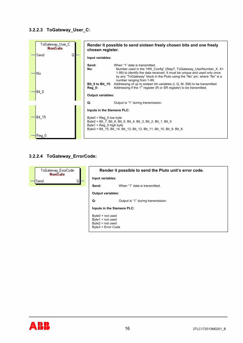
3.2.2.3 ToGateway_User_C:
Render it possible to send sixteen freely chosen bits and one freely chosen register. Input variables:
Send: When “1” data is transmitted. No: Number used in the “HW_Config” (Step7, ToGateway_UserNumber_X, X=
1-99) to identify the data received. It must be unique and used only once by any “ToGateway” block in the Pluto using the “No” pin, where “No” is a number ranging from 1-99.
Bit_0 to Bit_15: Addressing of up to sixteen bit variables (I, Q, M, SM) to be transmitted. Reg_0: Addressing if the 1st register (R or SR register) to be transmitted.
Output variables:
Q: Output is “1” during transmission.
Inputs in the Siemens PLC: Byte0 = Reg_0 low byte Byte2 = Bit_7, Bit_6, Bit_5, Bit_4, Bit_3, Bit_2, Bit_1, Bit_0 Byte1 = Reg_0 high byte Byte3 = Bit_15, Bit_14, Bit_13, Bit_12, Bit_11, Bit_10, Bit_9, Bit_8.
3.2.2.4 ToGateway_ErrorCode:
Render it possible to send the Pluto unit’s error code.
Input variables:
Send: When “1” data is transmitted. Output variables:
Q: Output is “1” during transmission.
Inputs in the Siemens PLC:
Byte0 = not used Byte1 = not used Byte2 = not used Byte3 = Error Code
16 2TLC172013M0201_B
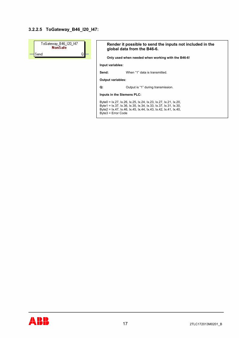
3.2.2.5 ToGateway_B46_I20_I47:
Render it possible to send the inputs not included in the global data from the B46-6. Only used when needed when working with the B46-6!
Input variables:
Send: When “1” data is transmitted. Output variables:
Q: Output is “1” during transmission.
Inputs in the Siemens PLC:
Byte0 = Ix.27, Ix.26, Ix.25, Ix.24, Ix.23, Ix.27, Ix.21, Ix.20, Byte1 = Ix.37, Ix.36, Ix.35, Ix.34, Ix.33, Ix.37, Ix.31, Ix.30, Byte2 = Ix.47, Ix.46, Ix.45, Ix.44, Ix.43, Ix.42, Ix.41, Ix.40, Byte3 = Error Code
17 2TLC172013M0201_B
3.3 Transmitting from the Siemens PLC to the Pluto
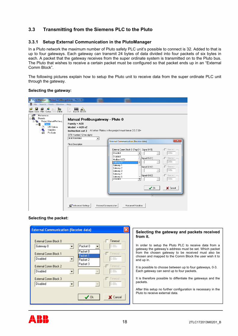
3.3.1 Setup External Communication in the PlutoManager In a Pluto network the maximum number of Pluto safety PLC unit’s possible to connect is 32. Added to that is up to four gateways. Each gateway can transmit 24 bytes of data divided into four packets of six bytes in each. A packet that the gateway receives from the super ordinate system is transmitted on to the Pluto bus. The Pluto that wishes to receive a certain packet must be configured so that packet ends up in an “External Comm Block”. The following pictures explain how to setup the Pluto unit to receive data from the super ordinate PLC unit through the gateway. Selecting the gateway:
Selecting the packet:
Selecting the gateway and packets received from it. In order to setup the Pluto PLC to receive data from a gateway the gateway’s address must be set. Which packet from the chosen gateway to be received must also be chosen and mapped to the Comm Block the user wish it to end up in. It is possible to choose between up to four gateways, 0-3. Each gateway can send up to four packets. It is therefore possible to diffentiate the gateways and the packets. After this setup no further configuration is necessary in the Pluto to receive external data.
18 2TLC172013M0201_B
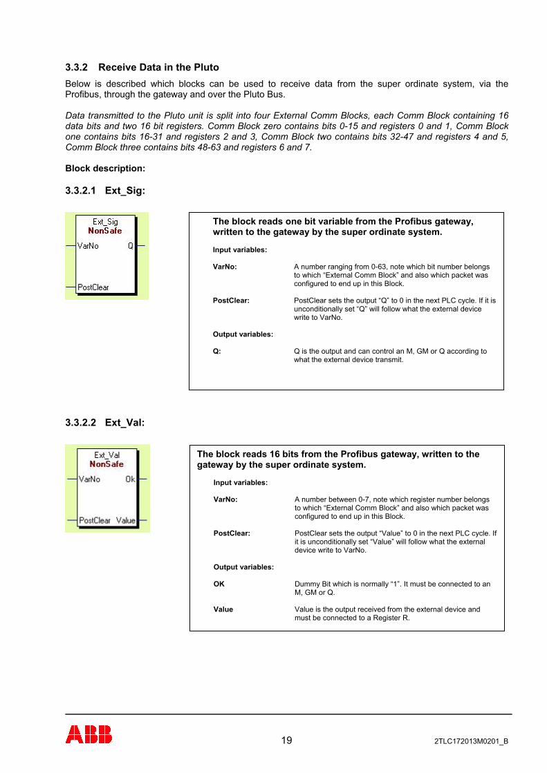
3.3.2 Receive Data in the Pluto Below is described which blocks can be used to receive data from the super ordinate system, via the Profibus, through the gateway and over the Pluto Bus. Data transmitted to the Pluto unit is split into four External Comm Blocks, each Comm Block containing 16 data bits and two 16 bit registers. Comm Block zero contains bits 0-15 and registers 0 and 1, Comm Block one contains bits 16-31 and registers 2 and 3, Comm Block two contains bits 32-47 and registers 4 and 5, Comm Block three contains bits 48-63 and registers 6 and 7. Block description:
3.3.2.1 Ext_Sig:
The block reads one bit variable from the Profibus gateway, written to the gateway by the super ordinate system. Input variables: VarNo: A number ranging from 0-63, note which bit number belongs
to which “External Comm Block” and also which packet was configured to end up in this Block.
PostClear: PostClear sets the output “Q” to 0 in the next PLC cycle. If it is
unconditionally set “Q” will follow what the external device write to VarNo.
Output variables: Q: Q is the output and can control an M, GM or Q according to
what the external device transmit.
3.3.2.2 Ext_Val:
19 2TLC172013M0201_B
The block reads 16 bits from the Profibus gateway, written to the gateway by the super ordinate system.
Input variables: VarNo: A number between 0-7, note which register number belongs
to which “External Comm Block” and also which packet was configured to end up in this Block.
PostClear: PostClear sets the output “Value” to 0 in the next PLC cycle. If
it is unconditionally set “Value” will follow what the external device write to VarNo.
Output variables: OK Dummy Bit which is normally “1”. It must be connected to an
M, GM or Q. Value Value is the output received from the external device and
must be connected to a Register R.

3.3.2.3 ExtVarBlock:
The block reads the whole packet received into an “External Comm Block” from the gateway, written to the gateway by the super ordinate system.
Input variables: BlockNo: A number between 0-3 corresponding to the External Comm
Block that is setup in PlutoManager.
Output variables: OK: Dummy Bit which is normally “1”. It must be connected to an
M, GM or Q. Bit_0 to Bit_15: The bits included in the Comm block, it must be connected to
an M, GM or Q. Reg_0: The first register included in the Comm block. It must be
written to a register R. Reg_1: The second register included in the Comm block. It must be
written to a register R.
20 2TLC172013M0201_B
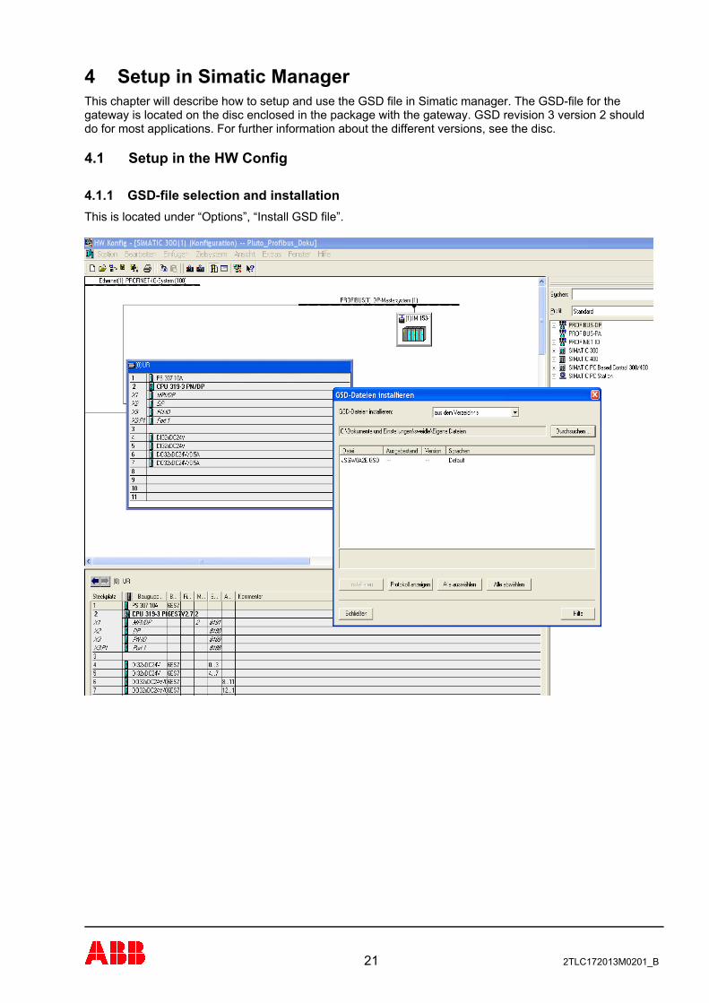
4 Setup in Simatic Manager This chapter will describe how to setup and use the GSD file in Simatic manager. The GSD-file for the gateway is located on the disc enclosed in the package with the gateway. GSD revision 3 version 2 should do for most applications. For further information about the different versions, see the disc.
4.1 Setup in the HW Config
4.1.1 GSD-file selection and installation This is located under “Options”, “Install GSD file”.
21 2TLC172013M0201_B
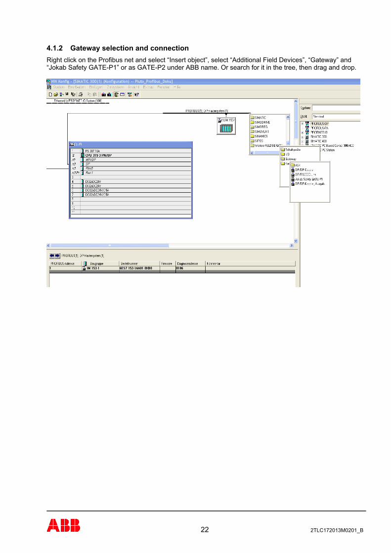
4.1.2 Gateway selection and connection Right click on the Profibus net and select “Insert object”, select “Additional Field Devices”, “Gateway” and “Jokab Safety GATE-P1” or as GATE-P2 under ABB name. Or search for it in the tree, then drag and drop.
22 2TLC172013M0201_B
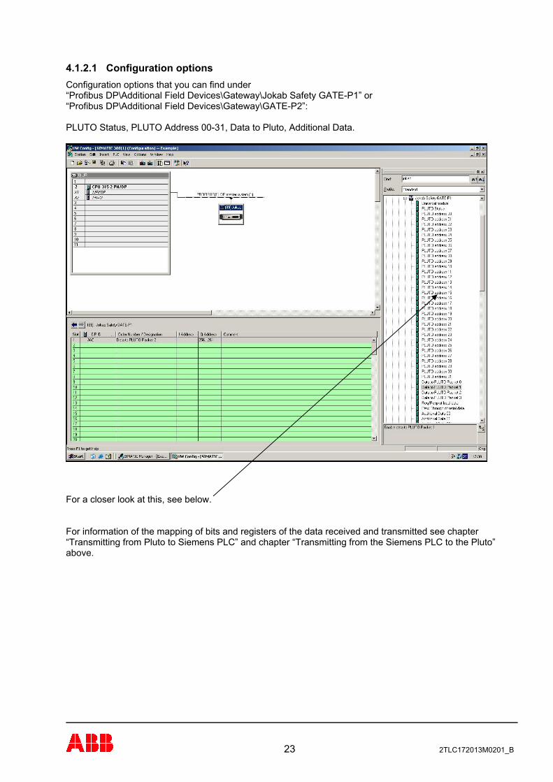
4.1.2.1 Configuration options Configuration options that you can find under “Profibus DP\Additional Field Devices\Gateway\Jokab Safety GATE-P1” or “Profibus DP\Additional Field Devices\Gateway\GATE-P2”: PLUTO Status, PLUTO Address 00-31, Data to Pluto, Additional Data.
23 2TLC172013M0201_B
For a closer look at this, see below. For information of the mapping of bits and registers of the data received and transmitted see chapter “Transmitting from Pluto to Siemens PLC” and chapter “Transmitting from the Siemens PLC to the Pluto” above.
24 2TLC172013M0201_B
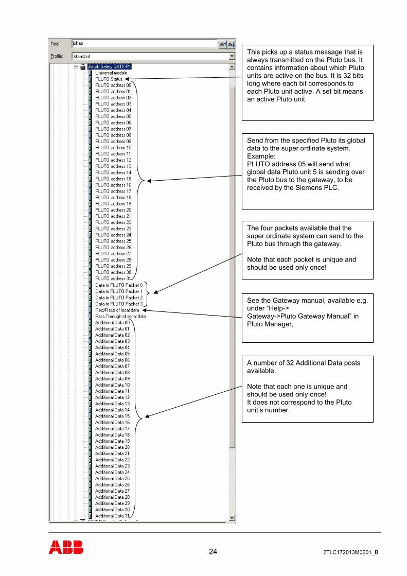
This picks up a status message that is always transmitted on the Pluto bus. It contains information about which Pluto units are active on the bus. It is 32 bits long where each bit corresponds to each Pluto unit active. A set bit means an active Pluto unit.
Send from the specified Pluto its global data to the super ordinate system. Example: PLUTO address 05 will send what global data Pluto unit 5 is sending over the Pluto bus to the gateway, to be received by the Siemens PLC.
The four packets available that the super ordinate system can send to the Pluto bus through the gateway. Note that each packet is unique and should be used only once!
See the Gateway manual, available e.g. under “Help-> Gateway->Pluto Gateway Manual” in Pluto Manager,
A number of 32 Additional Data posts available. Note that each one is unique and should be used only once! It does not correspond to the Pluto unit’s number.
4.1.2.2 Req/Resp of local data This requires a special procedure to be used described more thoroughly in the Gateway Manual.
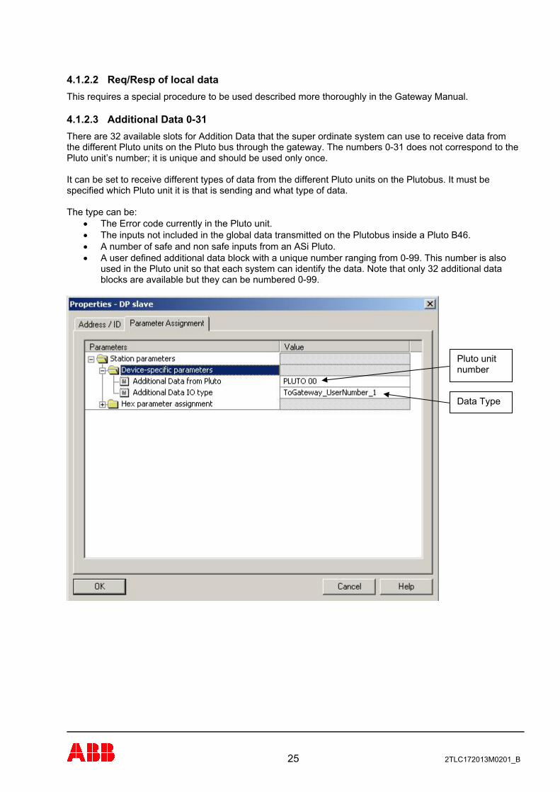
4.1.2.3 Additional Data 0-31 There are 32 available slots for Addition Data that the super ordinate system can use to receive data from the different Pluto units on the Pluto bus through the gateway. The numbers 0-31 does not correspond to the Pluto unit’s number; it is unique and should be used only once. It can be set to receive different types of data from the different Pluto units on the Plutobus. It must be specified which Pluto unit it is that is sending and what type of data. The type can be:
• The Error code currently in the Pluto unit. • The inputs not included in the global data transmitted on the Plutobus inside a Pluto B46. • A number of safe and non safe inputs from an ASi Pluto. • A user defined additional data block with a unique number ranging from 0-99. This number is also
used in the Pluto unit so that each system can identify the data. Note that only 32 additional data blocks are available but they can be numbered 0-99.
Pluto unit number
Data Type
25 2TLC172013M0201_B
4.2 Function block library Included on the disc provided with the Gateway there is a function library called “GATE-P1 S7 Block.zip”. It is open and fully modifiable and provided for free. They are to be used “as is”.
4.2.1 Installation In Simatic Manager go to the “File” menu and choose “Retrieve”. Select “GATE-P1 S7 Block.zip” when prompted to do so. Select “S7LIBS” in your Siemens Step7 install path. The library “Jokab” can now be viewed under the “File” menu when clicking “Manage”, and then clicking the “Libraries” tab.
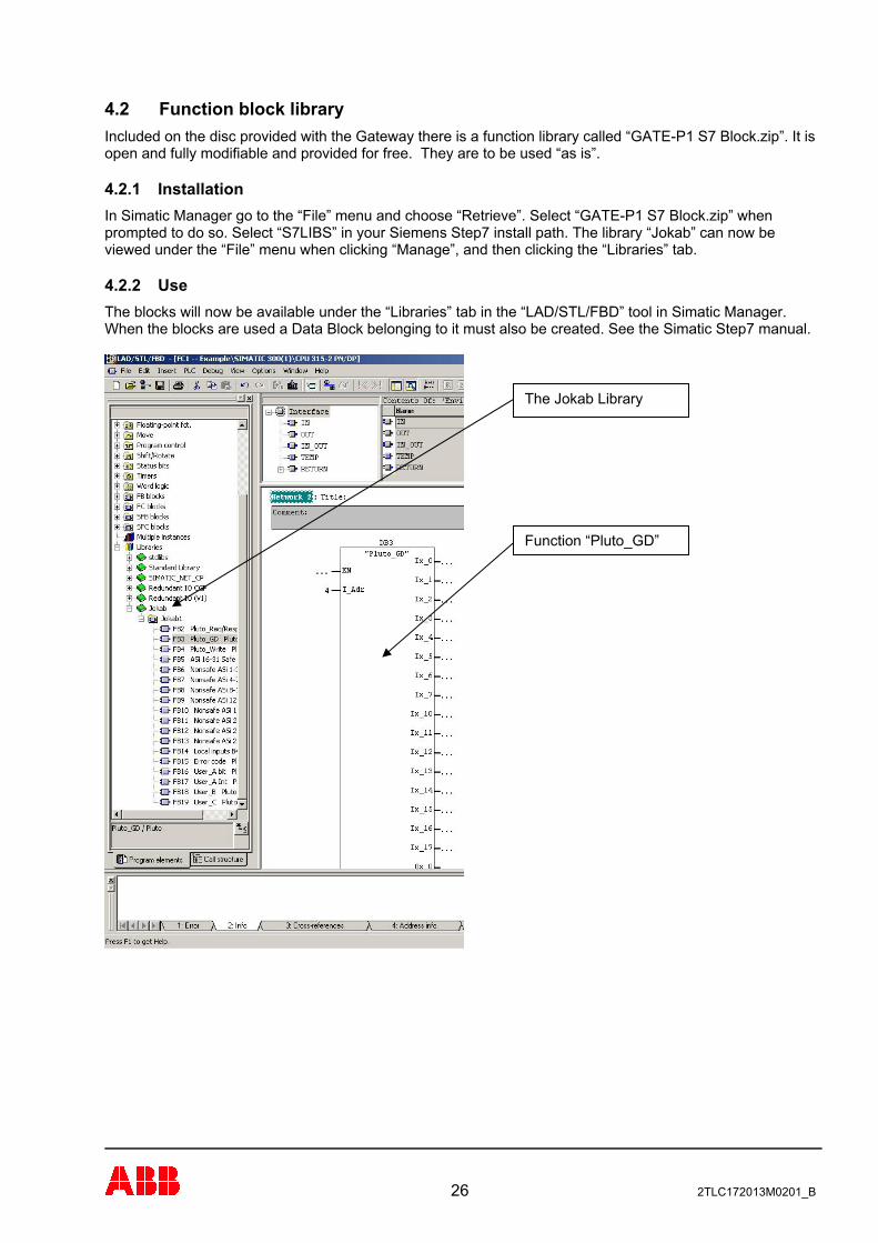
4.2.2 Use The blocks will now be available under the “Libraries” tab in the “LAD/STL/FBD” tool in Simatic Manager. When the blocks are used a Data Block belonging to it must also be created. See the Simatic Step7 manual.
The Jokab Library
Function “Pluto_GD”
26 2TLC172013M0201_B
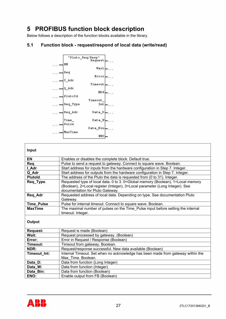
5 PROFIBUS function block description Below follows a description of the function blocks available in the library.
5.1 Function block - request/respond of local data (write/read)
Input EN Enables or disables the complete block. Default true. Req Pulse to send a request to gateway. Connect to square wave. Boolean. I_Adr Start address for inputs from the hardware configuration in Step 7. Integer. Q_Adr Start address for outputs from the hardware configuration in Step 7. Integer. PlutoId. The address of the Pluto the data is requested from (0 to 31). Integer. Req_Type. Requested type of local data. 0 to 3. 0=Global memory (Boolean), 1=Local memory
(Boolean), 2=Local register (Integer), 3=Local parameter (Long Integer). See documentation for Pluto Gateway.
Req_Adr Requested address of local data. Depending on type. See documentation Pluto Gateway.
Time_Pulse Pulse for internal timeout. Connect to square wave. Boolean. MaxTime The maximal number of pulses on the Time_Pulse input before setting the internal
timeout. Integer. Output Request: Request is made (Boolean) Wait: Request processed by gateway. (Boolean) Error: Error in Request / Response (Boolean) Timeout: Timeout from gateway. Boolean. NDR: Request/response successful. New data available (Boolean) Timeout_Int: Internal Timeout. Set when no acknowledge has been made from gateway within the
Max_Time. Boolean. Data_D: Data from function (Long Integer) Data_W: Data from function (Integer) Data_Bin: Data from function (Boolean) ENO: Enable output from FB (Boolean)
27 2TLC172013M0201_B
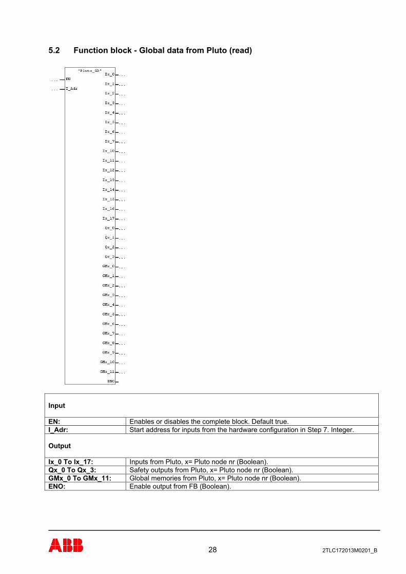
5.2 Function block - Global data from Pluto (read)
Input EN: Enables or disables the complete block. Default true. I_Adr: Start address for inputs from the hardware configuration in Step 7. Integer. Output Ix_0 To Ix_17: Inputs from Pluto, x= Pluto node nr (Boolean). Qx_0 To Qx_3: Safety outputs from Pluto, x= Pluto node nr (Boolean). GMx_0 To GMx_11: Global memories from Pluto, x= Pluto node nr (Boolean). ENO: Enable output from FB (Boolean).
28 2TLC172013M0201_B
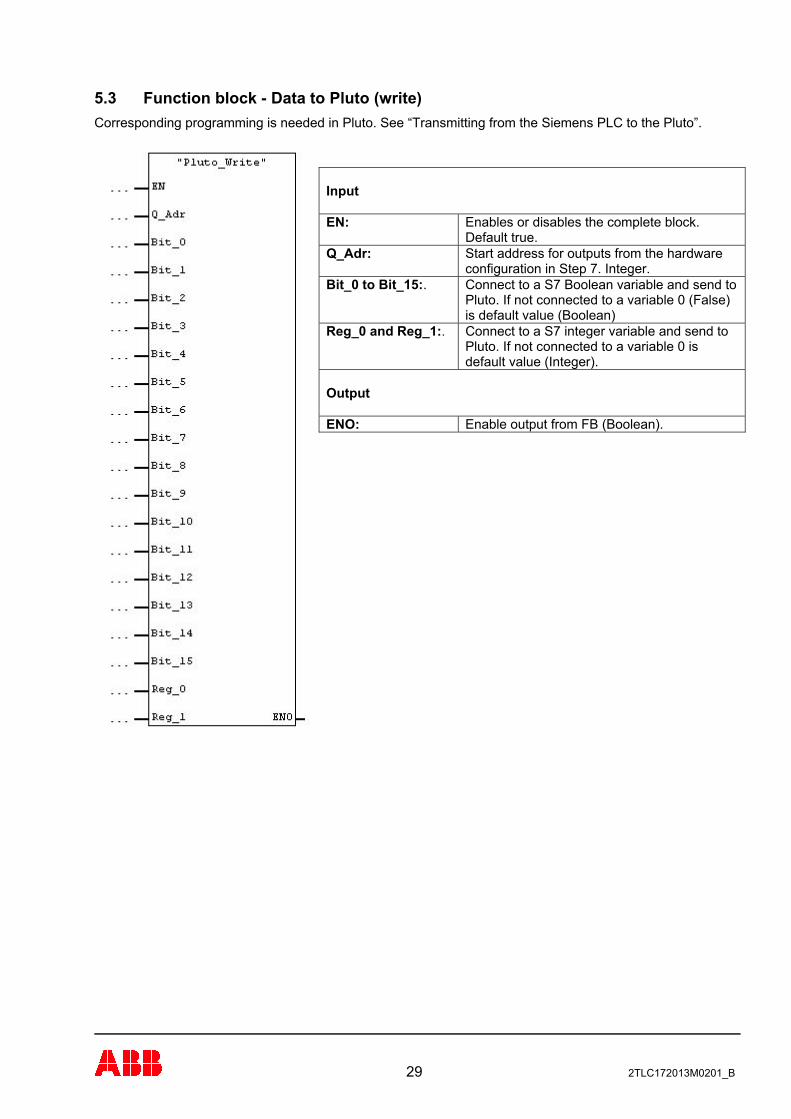
5.3 Function block - Data to Pluto (write) Corresponding programming is needed in Pluto. See “Transmitting from the Siemens PLC to the Pluto”.
Input
Enables or disables the complete block. Default true.
EN:
Start address for outputs from the hardware configuration in Step 7. Integer.
Q_Adr:
Bit_0 to Bit_15:. Connect to a S7 Boolean variable and send to Pluto. If not connected to a variable 0 (False) is default value (Boolean)
Reg_0 and Reg_1:. Connect to a S7 integer variable and send to Pluto. If not connected to a variable 0 is default value (Integer).
Output
Enable output from FB (Boolean). ENO:
29 2TLC172013M0201_B
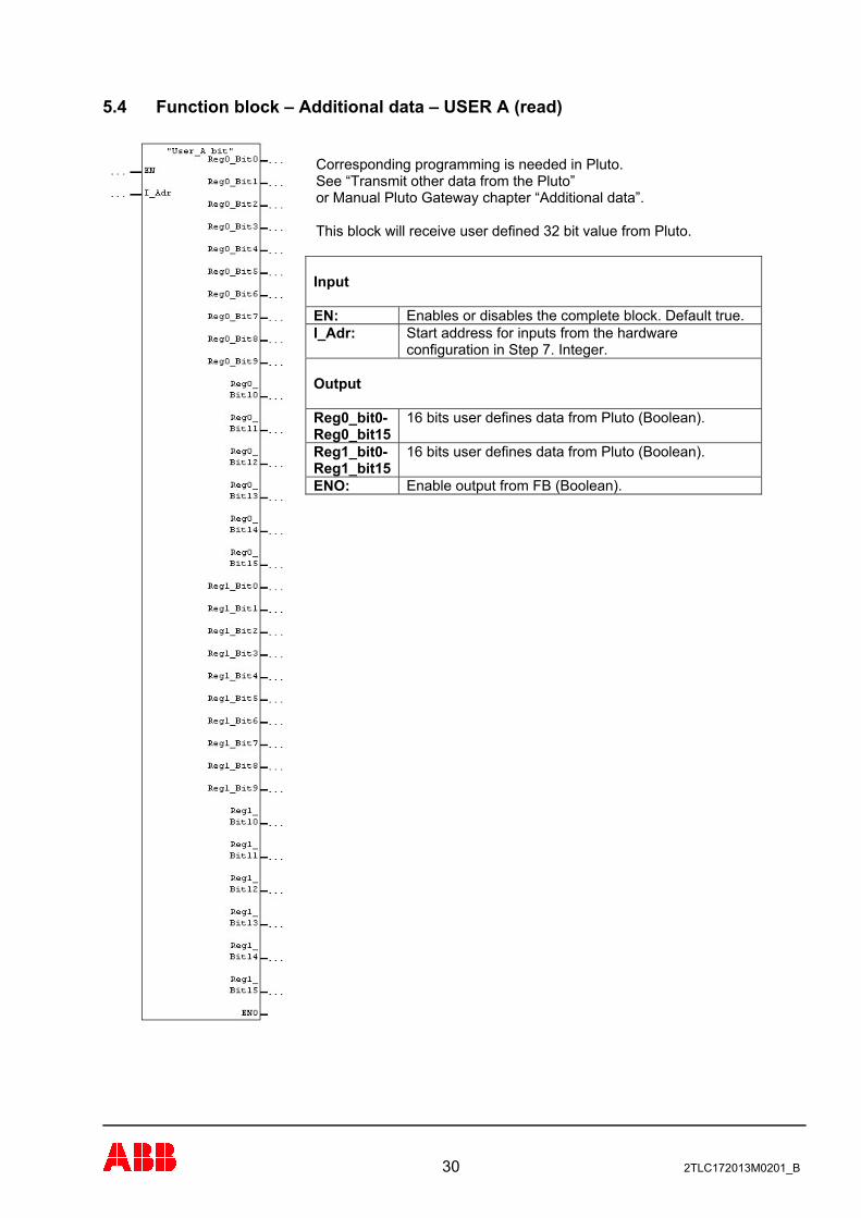
5.4 Function block – Additional data – USER A (read)
Corresponding programming is needed in Pluto. See “Transmit other data from the Pluto” or Manual Pluto Gateway chapter “Additional data”. This block will receive user defined 32 bit value from Pluto. Input
Enables or disables the complete block. Default true. EN: Start address for inputs from the hardware configuration in Step 7. Integer.
I_Adr:
Output
16 bits user defines data from Pluto (Boolean). Reg0_bit0- Reg0_bit15
16 bits user defines data from Pluto (Boolean). Reg1_bit0- Reg1_bit15
Enable output from FB (Boolean). ENO:
30 2TLC172013M0201_B
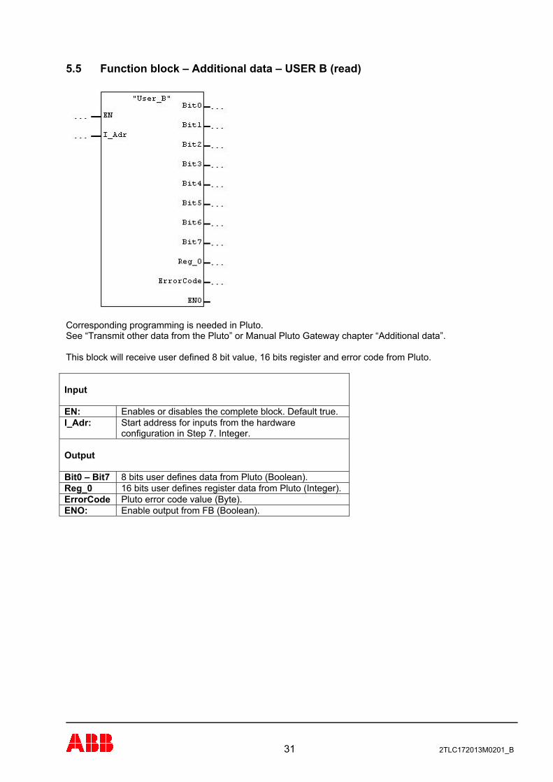
5.5 Function block – Additional data – USER B (read)
Corresponding programming is needed in Pluto. See “Transmit other data from the Pluto” or Manual Pluto Gateway chapter “Additional data”. This block will receive user defined 8 bit value, 16 bits register and error code from Pluto. Input EN: Enables or disables the complete block. Default true. I_Adr: Start address for inputs from the hardware
configuration in Step 7. Integer. Output Bit0 – Bit7 8 bits user defines data from Pluto (Boolean). Reg_0 16 bits user defines register data from Pluto (Integer). ErrorCode Pluto error code value (Byte). ENO: Enable output from FB (Boolean).
31 2TLC172013M0201_B
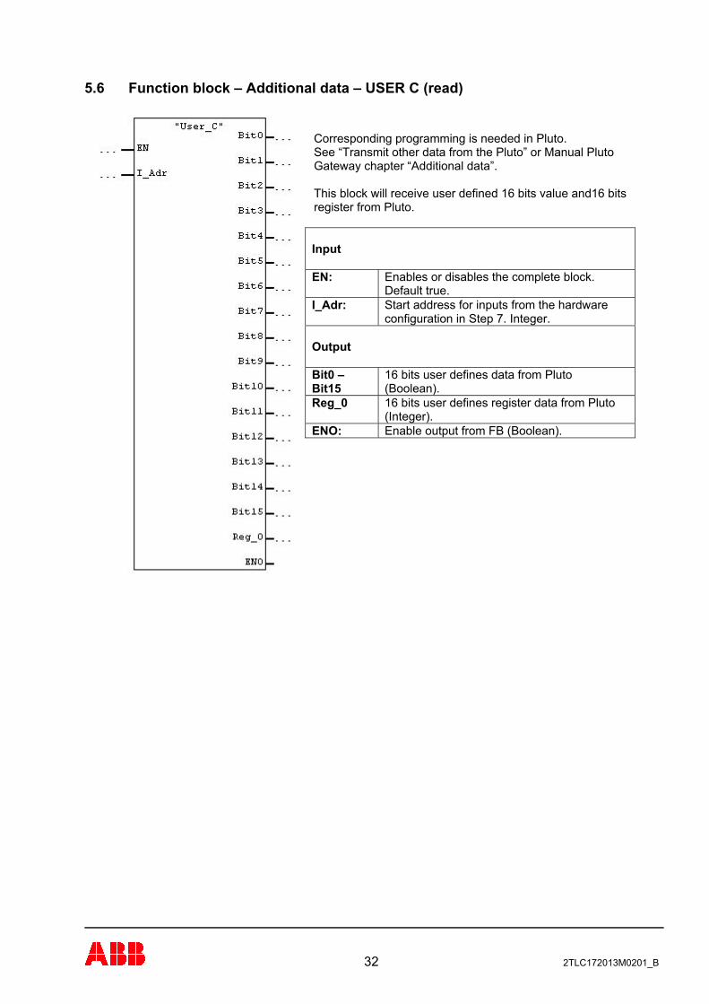
5.6 Function block – Additional data – USER C (read)
Corresponding programming is needed in Pluto. See “Transmit other data from the Pluto” or Manual Pluto Gateway chapter “Additional data”. This block will receive user defined 16 bits value and16 bits register from Pluto. Input
Enables or disables the complete block. Default true.
EN:
Start address for inputs from the hardware configuration in Step 7. Integer.
I_Adr:
Output
16 bits user defines data from Pluto (Boolean).
Bit0 – Bit15
16 bits user defines register data from Pluto (Integer).
Reg_0
Enable output from FB (Boolean). ENO:
32 2TLC172013M0201_B
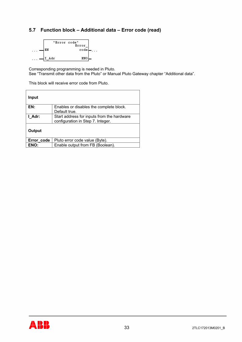
5.7 Function block – Additional data – Error code (read)
Corresponding programming is needed in Pluto. See “Transmit other data from the Pluto” or Manual Pluto Gateway chapter “Additional data”. This block will receive error code from Pluto. Input EN: Enables or disables the complete block.
Default true. I_Adr: Start address for inputs from the hardware
configuration in Step 7. Integer. Output Error_code Pluto error code value (Byte). ENO: Enable output from FB (Boolean).
33 2TLC172013M0201_B
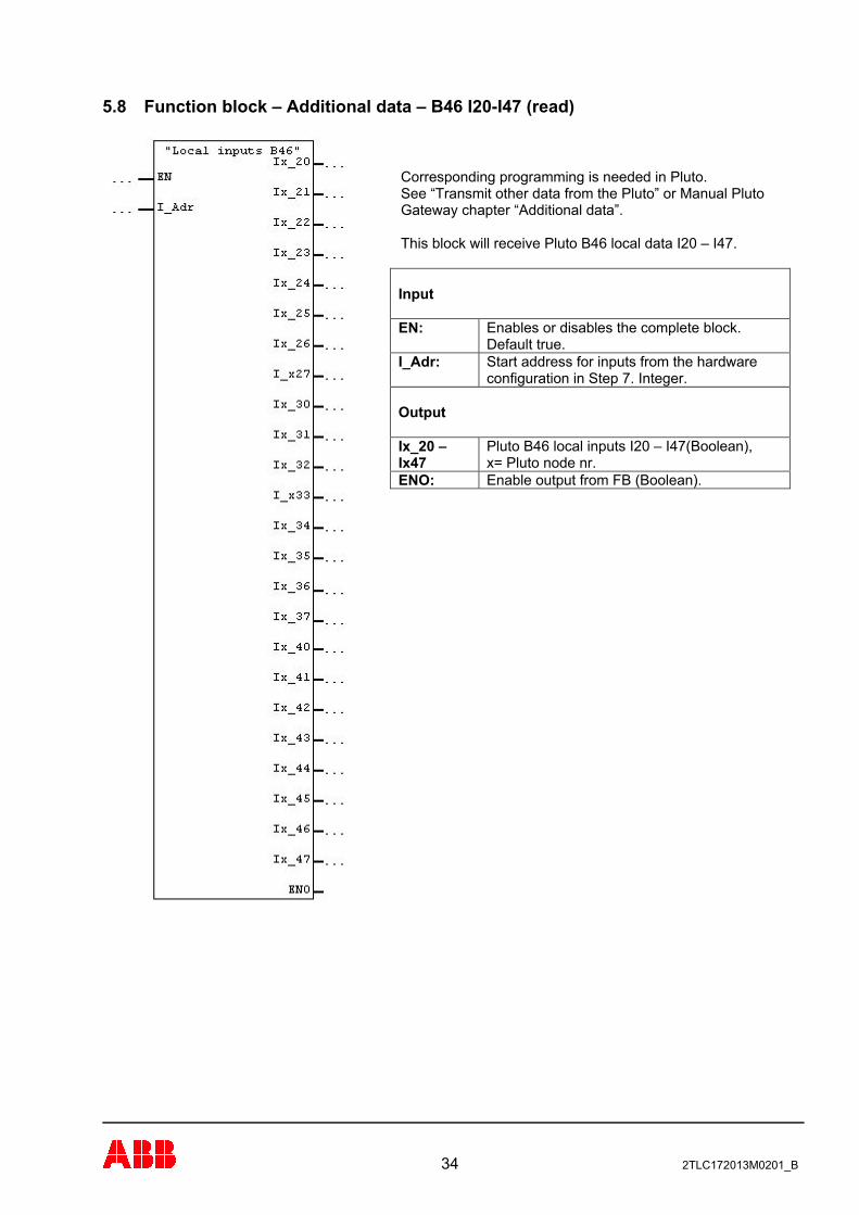
5.8 Function block – Additional data – B46 I20-I47 (read)
Corresponding programming is needed in Pluto. See “Transmit other data from the Pluto” or Manual Pluto Gateway chapter “Additional data”. This block will receive Pluto B46 local data I20 – I47. Input
Enables or disables the complete block. Default true.
EN:
Start address for inputs from the hardware configuration in Step 7. Integer.
I_Adr:
Output
Pluto B46 local inputs I20 – I47(Boolean), x= Pluto node nr.
Ix_20 – Ix47
Enable output from FB (Boolean). ENO:
34 2TLC172013M0201_B
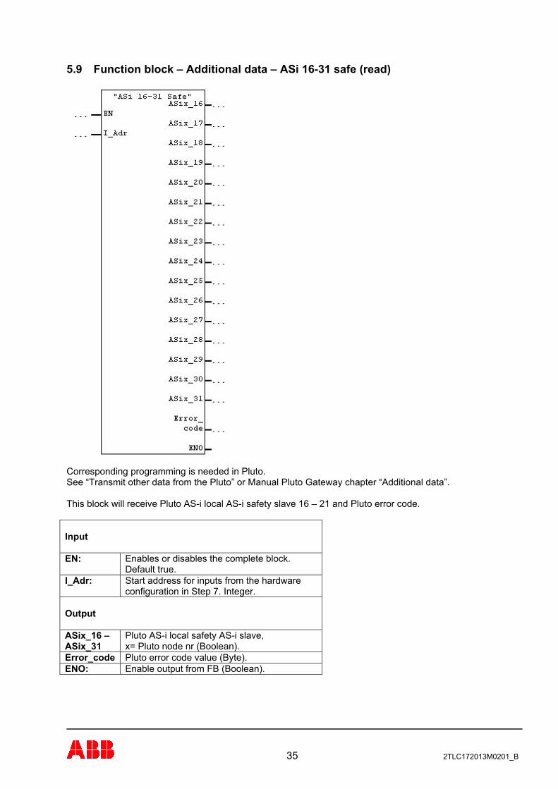
5.9 Function block – Additional data – ASi 16-31 safe (read)
Corresponding programming is needed in Pluto. See “Transmit other data from the Pluto” or Manual Pluto Gateway chapter “Additional data”. This block will receive Pluto AS-i local AS-i safety slave 16 – 21 and Pluto error code. Input EN: Enables or disables the complete block.
Default true. I_Adr: Start address for inputs from the hardware
configuration in Step 7. Integer. Output ASix_16 – ASix_31
Pluto AS-i local safety AS-i slave, x= Pluto node nr (Boolean).
Error_code Pluto error code value (Byte). ENO: Enable output from FB (Boolean).
35 2TLC172013M0201_B
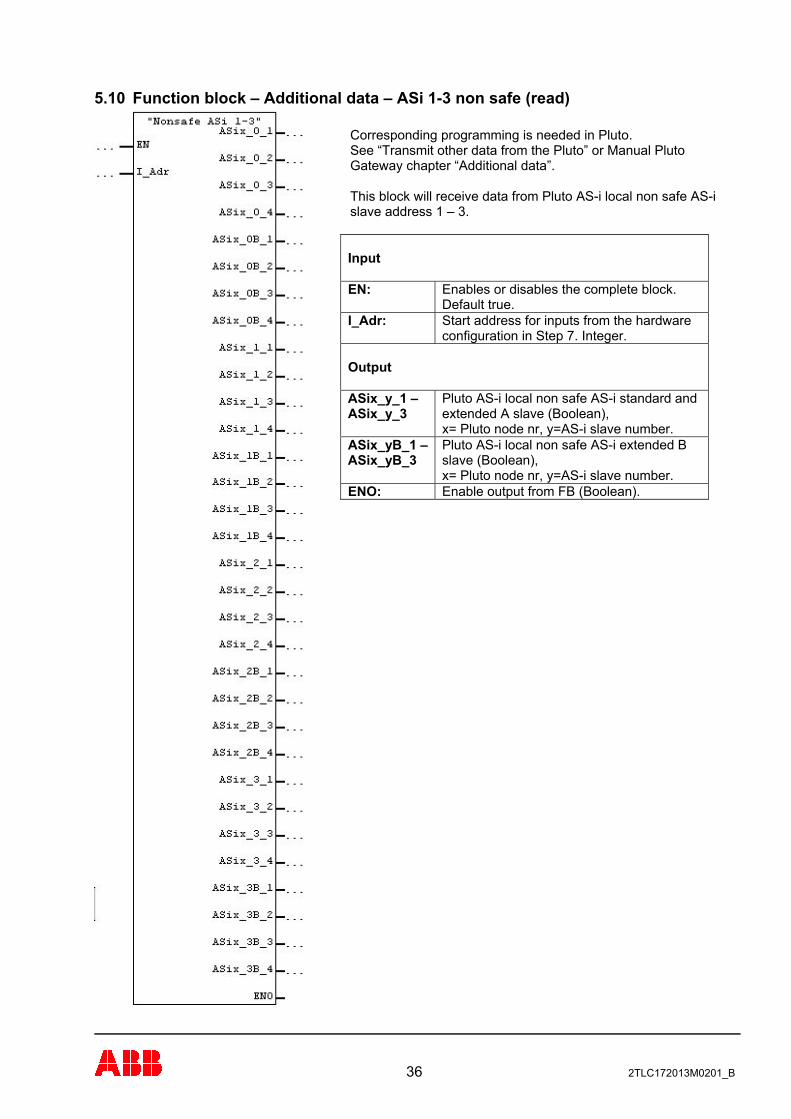
5.10 Function block – Additional data – ASi 1-3 non safe (read)
Corresponding programming is needed in Pluto. See “Transmit other data from the Pluto” or Manual Pluto Gateway chapter “Additional data”. This block will receive data from Pluto AS-i local non safe AS-i slave address 1 – 3. Input
Enables or disables the complete block. Default true.
EN:
Start address for inputs from the hardware configuration in Step 7. Integer.
I_Adr:
Output
Pluto AS-i local non safe AS-i standard and extended A slave (Boolean), x= Pluto node nr, y=AS-i slave number.
ASix_y_1 – ASix_y_3
Pluto AS-i local non safe AS-i extended B slave (Boolean), x= Pluto node nr, y=AS-i slave number.
ASix_yB_1 – ASix_yB_3
Enable output from FB (Boolean). ENO:
36 2TLC172013M0201_B
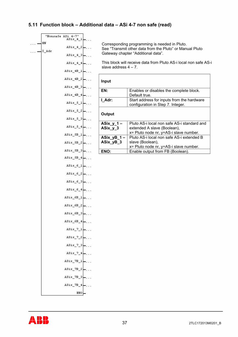
5.11 Function block – Additional data – ASi 4-7 non safe (read)
Corresponding programming is needed in Pluto. See “Transmit other data from the Pluto” or Manual Pluto Gateway chapter “Additional data”. This block will receive data from Pluto AS-i local non safe AS-i slave address 4 – 7. Input
Enables or disables the complete block. Default true.
EN:
Start address for inputs from the hardware configuration in Step 7. Integer.
I_Adr:
Output
Pluto AS-i local non safe AS-i standard and extended A slave (Boolean), x= Pluto node nr, y=AS-i slave number.
ASix_y_1 – ASix_y_3
Pluto AS-i local non safe AS-i extended B slave (Boolean), x= Pluto node nr, y=AS-i slave number.
ASix_yB_1 – ASix_yB_3
Enable output from FB (Boolean). ENO:
37 2TLC172013M0201_B
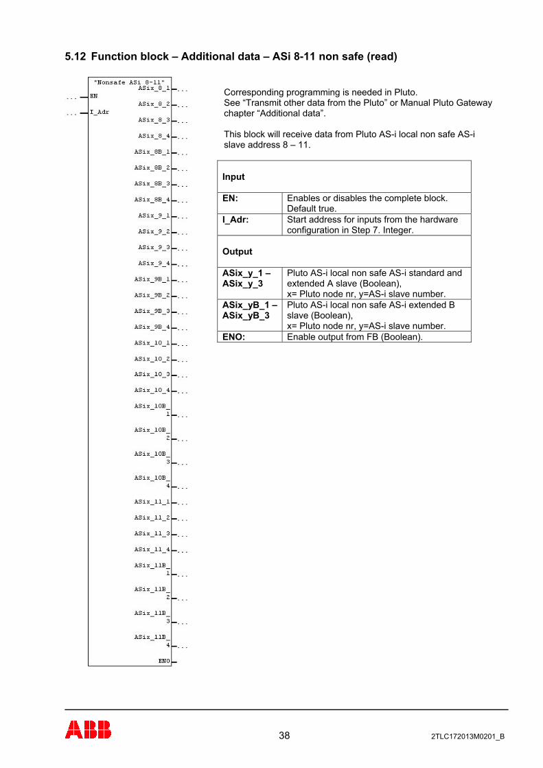
5.12 Function block – Additional data – ASi 8-11 non safe (read)
Corresponding programming is needed in Pluto. See “Transmit other data from the Pluto” or Manual Pluto Gateway chapter “Additional data”. This block will receive data from Pluto AS-i local non safe AS-i slave address 8 – 11. Input
Enables or disables the complete block. Default true.
EN:
Start address for inputs from the hardware configuration in Step 7. Integer.
I_Adr:
Output
Pluto AS-i local non safe AS-i standard and extended A slave (Boolean), x= Pluto node nr, y=AS-i slave number.
ASix_y_1 – ASix_y_3
Pluto AS-i local non safe AS-i extended B slave (Boolean), x= Pluto node nr, y=AS-i slave number.
ASix_yB_1 – ASix_yB_3
Enable output from FB (Boolean). ENO:
38 2TLC172013M0201_B
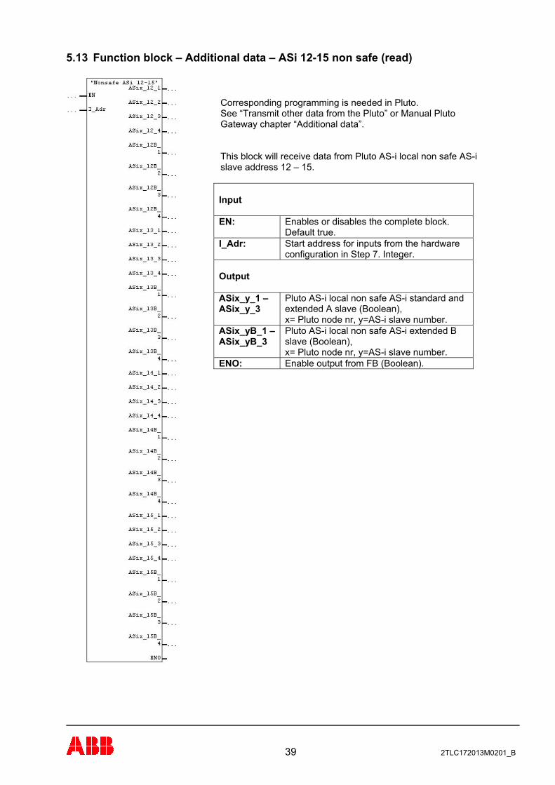
5.13 Function block – Additional data – ASi 12-15 non safe (read)
Corresponding programming is needed in Pluto. See “Transmit other data from the Pluto” or Manual Pluto Gateway chapter “Additional data”. This block will receive data from Pluto AS-i local non safe AS-i slave address 12 – 15. Input
Enables or disables the complete block. Default true.
EN:
Start address for inputs from the hardware configuration in Step 7. Integer.
I_Adr:
Output
Pluto AS-i local non safe AS-i standard and extended A slave (Boolean), x= Pluto node nr, y=AS-i slave number.
ASix_y_1 – ASix_y_3
Pluto AS-i local non safe AS-i extended B slave (Boolean), x= Pluto node nr, y=AS-i slave number.
ASix_yB_1 – ASix_yB_3
Enable output from FB (Boolean). ENO:
39 2TLC172013M0201_B
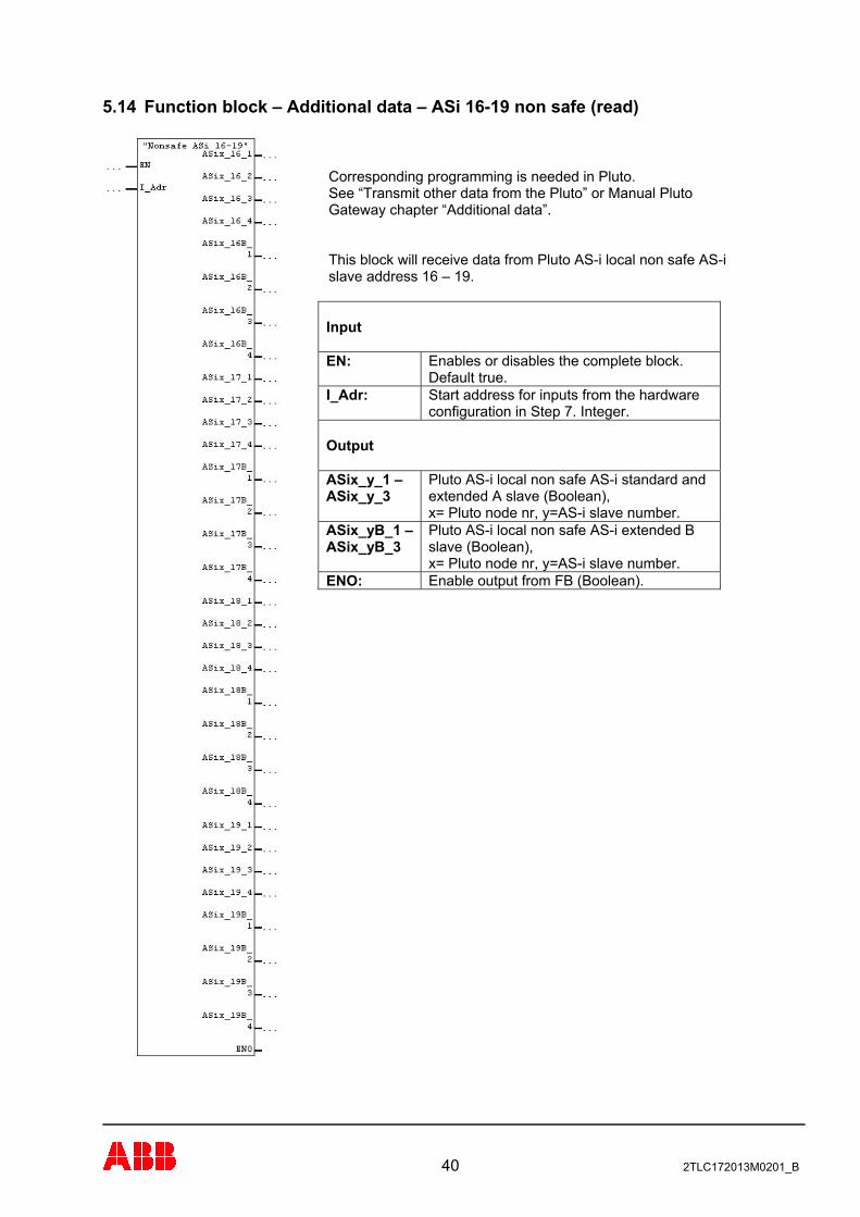
5.14 Function block – Additional data – ASi 16-19 non safe (read)
Corresponding programming is needed in Pluto. See “Transmit other data from the Pluto” or Manual Pluto Gateway chapter “Additional data”. This block will receive data from Pluto AS-i local non safe AS-i slave address 16 – 19. Input
Enables or disables the complete block. Default true.
EN:
Start address for inputs from the hardware configuration in Step 7. Integer.
I_Adr:
Output
Pluto AS-i local non safe AS-i standard and extended A slave (Boolean), x= Pluto node nr, y=AS-i slave number.
ASix_y_1 – ASix_y_3
Pluto AS-i local non safe AS-i extended B slave (Boolean), x= Pluto node nr, y=AS-i slave number.
ASix_yB_1 – ASix_yB_3
Enable output from FB (Boolean). ENO:
40 2TLC172013M0201_B
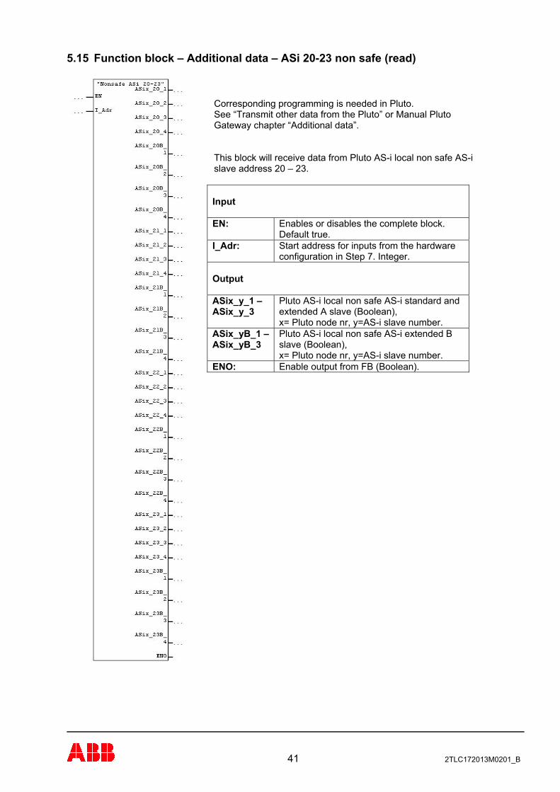
5.15 Function block – Additional data – ASi 20-23 non safe (read)
Corresponding programming is needed in Pluto. See “Transmit other data from the Pluto” or Manual Pluto Gateway chapter “Additional data”. This block will receive data from Pluto AS-i local non safe AS-i slave address 20 – 23. Input
Enables or disables the complete block. Default true.
EN:
Start address for inputs from the hardware configuration in Step 7. Integer.
I_Adr:
Output
Pluto AS-i local non safe AS-i standard and extended A slave (Boolean), x= Pluto node nr, y=AS-i slave number.
ASix_y_1 – ASix_y_3
Pluto AS-i local non safe AS-i extended B slave (Boolean), x= Pluto node nr, y=AS-i slave number.
ASix_yB_1 – ASix_yB_3
Enable output from FB (Boolean). ENO:
41 2TLC172013M0201_B
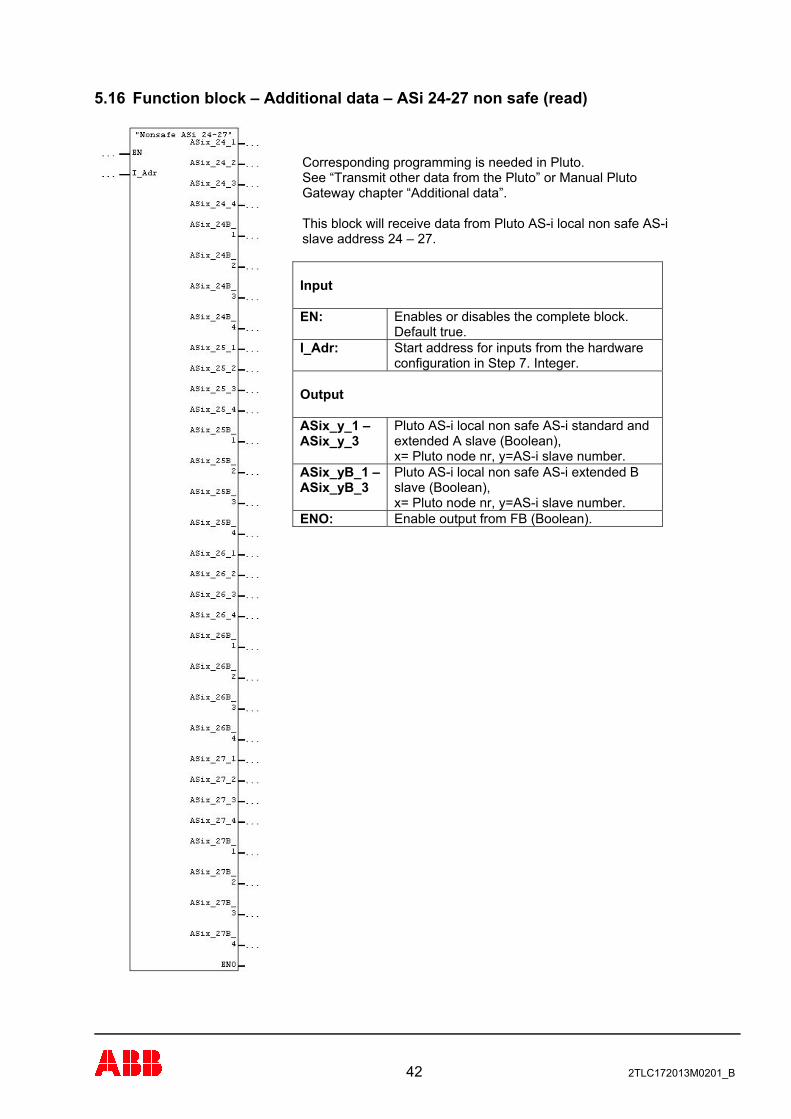
5.16 Function block – Additional data – ASi 24-27 non safe (read)
Corresponding programming is needed in Pluto. See “Transmit other data from the Pluto” or Manual Pluto Gateway chapter “Additional data”. This block will receive data from Pluto AS-i local non safe AS-i slave address 24 – 27. Input
Enables or disables the complete block. Default true.
EN:
Start address for inputs from the hardware configuration in Step 7. Integer.
I_Adr:
Output
Pluto AS-i local non safe AS-i standard and extended A slave (Boolean), x= Pluto node nr, y=AS-i slave number.
ASix_y_1 – ASix_y_3
Pluto AS-i local non safe AS-i extended B slave (Boolean), x= Pluto node nr, y=AS-i slave number.
ASix_yB_1 – ASix_yB_3
Enable output from FB (Boolean). ENO:
42 2TLC172013M0201_B
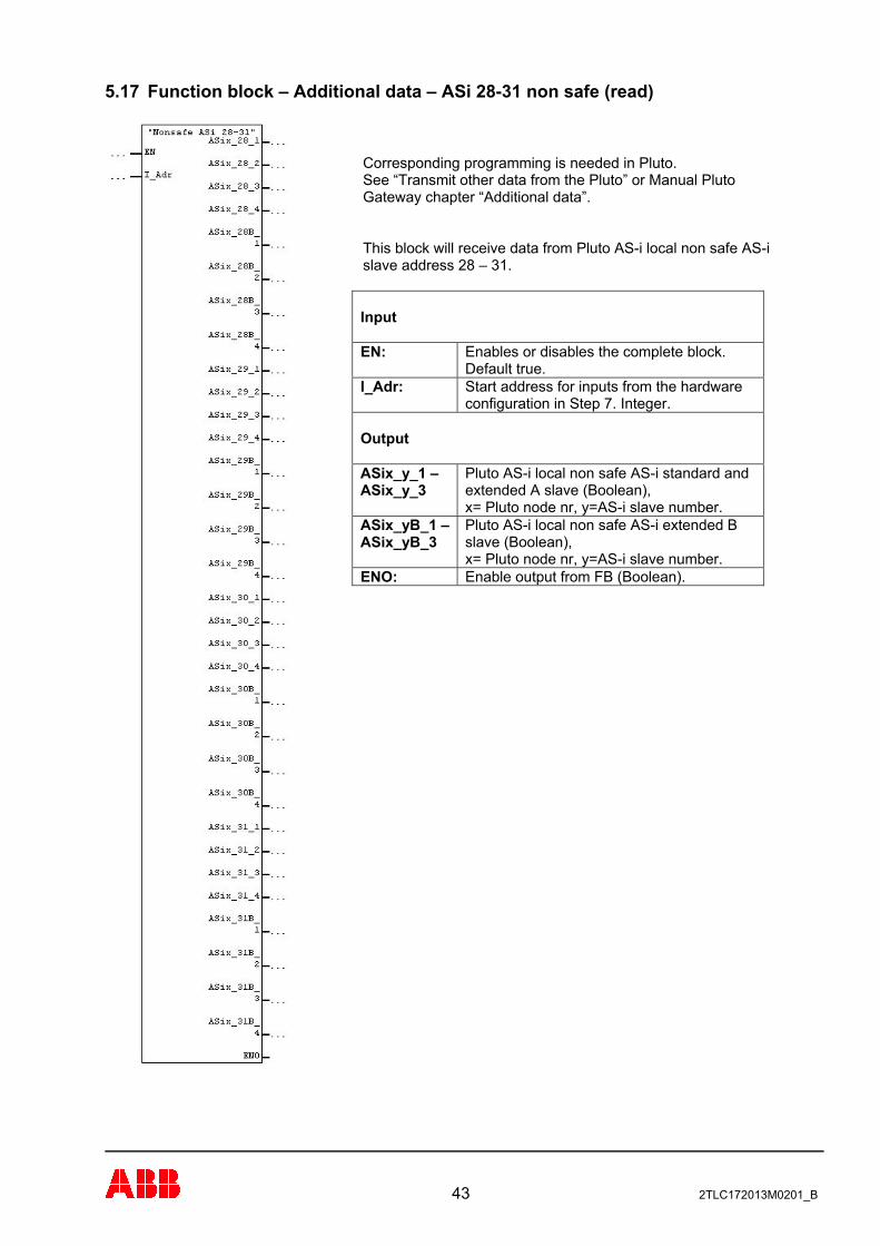
5.17 Function block – Additional data – ASi 28-31 non safe (read)
Corresponding programming is needed in Pluto. See “Transmit other data from the Pluto” or Manual Pluto Gateway chapter “Additional data”. This block will receive data from Pluto AS-i local non safe AS-i slave address 28 – 31. Input
Enables or disables the complete block. Default true.
EN:
Start address for inputs from the hardware configuration in Step 7. Integer.
I_Adr:
Output
Pluto AS-i local non safe AS-i standard and extended A slave (Boolean), x= Pluto node nr, y=AS-i slave number.
ASix_y_1 – ASix_y_3
Pluto AS-i local non safe AS-i extended B slave (Boolean), x= Pluto node nr, y=AS-i slave number.
ASix_yB_1 – ASix_yB_3
Enable output from FB (Boolean). ENO:
43 2TLC172013M0201_B

44 2TLC172013M0201_B
6 PROFINET function block description Below follows a description of the function blocks available in the library.
6.1 General This document describes sample function blocks for the Siemens S7 PLC family to communicate with Jokab Safety Pluto PLC’s via ProfiNet. All functions are samples and are to be used “as is”. Each instance of the FB’s need to be connected to an instance data block; see Step 7 manual.
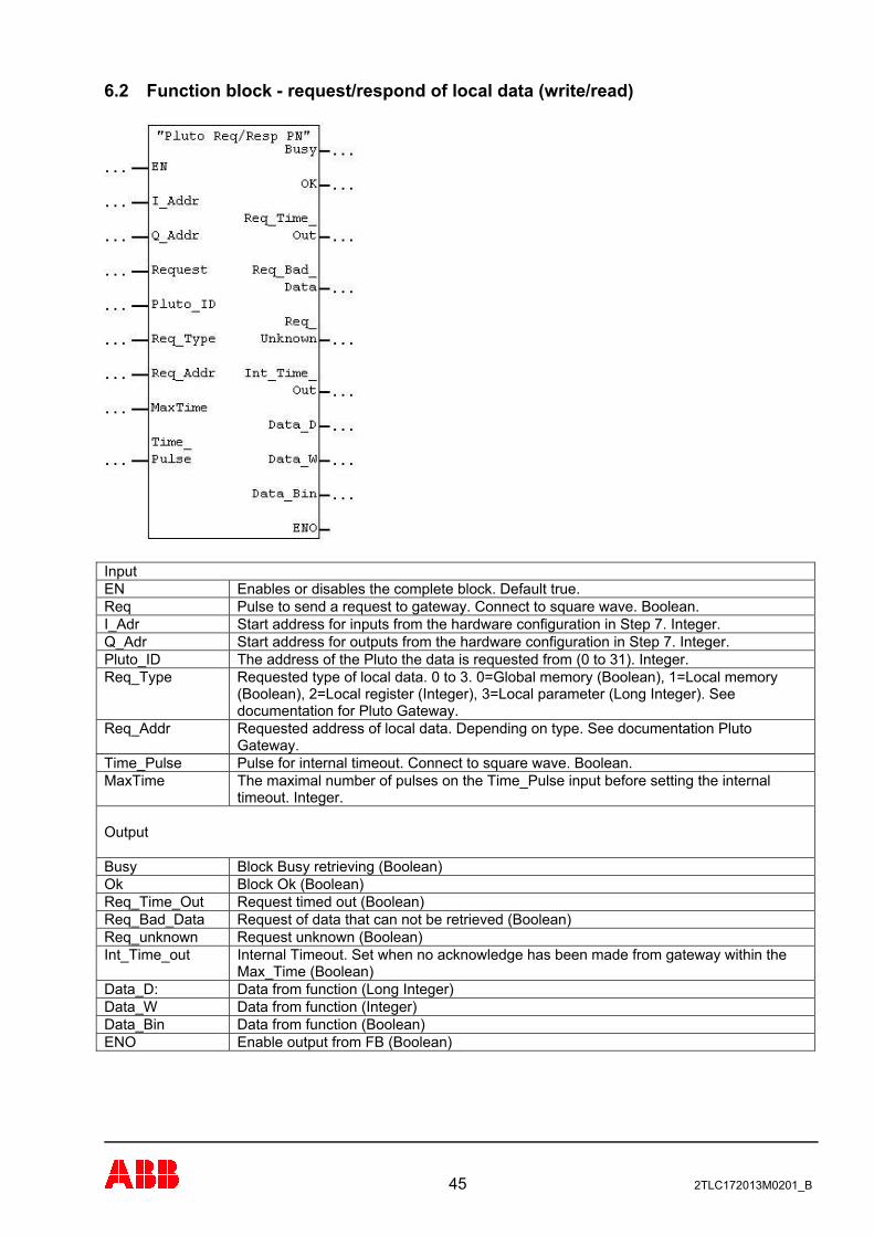
6.2 Function block - request/respond of local data (write/read)
Input EN Enables or disables the complete block. Default true. Req Pulse to send a request to gateway. Connect to square wave. Boolean. I_Adr Start address for inputs from the hardware configuration in Step 7. Integer. Q_Adr Start address for outputs from the hardware configuration in Step 7. Integer. Pluto_ID The address of the Pluto the data is requested from (0 to 31). Integer. Req_Type Requested type of local data. 0 to 3. 0=Global memory (Boolean), 1=Local memory
(Boolean), 2=Local register (Integer), 3=Local parameter (Long Integer). See documentation for Pluto Gateway.
Req_Addr Requested address of local data. Depending on type. See documentation Pluto Gateway.
Time_Pulse Pulse for internal timeout. Connect to square wave. Boolean. MaxTime The maximal number of pulses on the Time_Pulse input before setting the internal
timeout. Integer. Output Busy Block Busy retrieving (Boolean) Ok Block Ok (Boolean) Req_Time_Out Request timed out (Boolean) Req_Bad_Data Request of data that can not be retrieved (Boolean) Req_unknown Request unknown (Boolean) Int_Time_out Internal Timeout. Set when no acknowledge has been made from gateway within the
Max_Time (Boolean) Data_D: Data from function (Long Integer) Data_W Data from function (Integer) Data_Bin Data from function (Boolean) ENO Enable output from FB (Boolean)
45 2TLC172013M0201_B
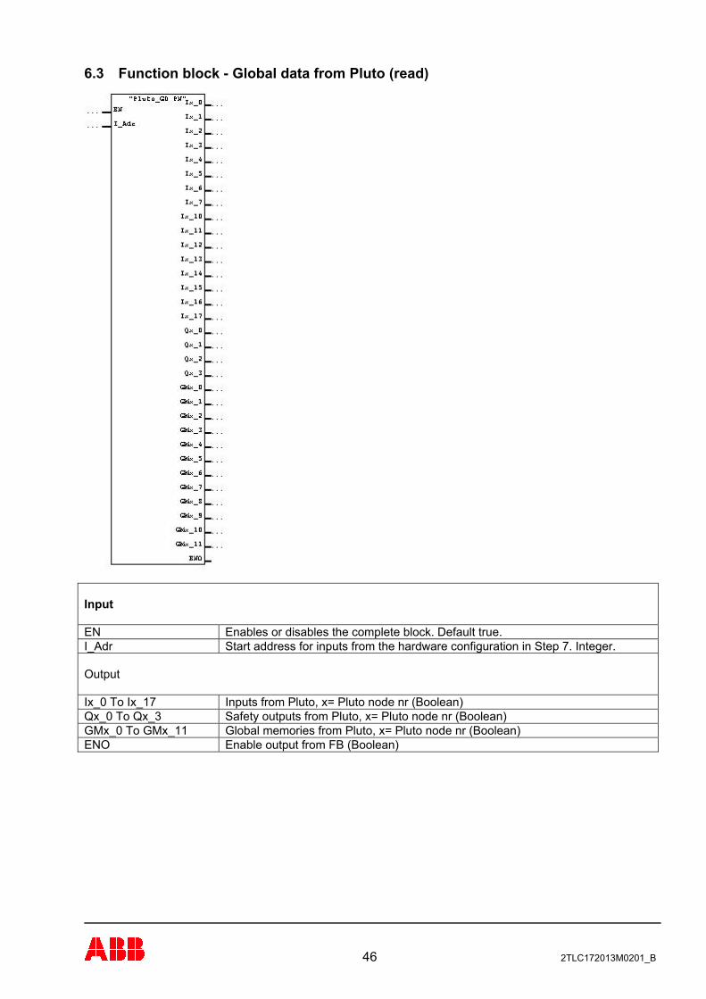
6.3 Function block - Global data from Pluto (read)
Input EN Enables or disables the complete block. Default true. I_Adr Start address for inputs from the hardware configuration in Step 7. Integer. Output Ix_0 To Ix_17 Inputs from Pluto, x= Pluto node nr (Boolean) Qx_0 To Qx_3 Safety outputs from Pluto, x= Pluto node nr (Boolean) GMx_0 To GMx_11 Global memories from Pluto, x= Pluto node nr (Boolean) ENO Enable output from FB (Boolean)
46 2TLC172013M0201_B
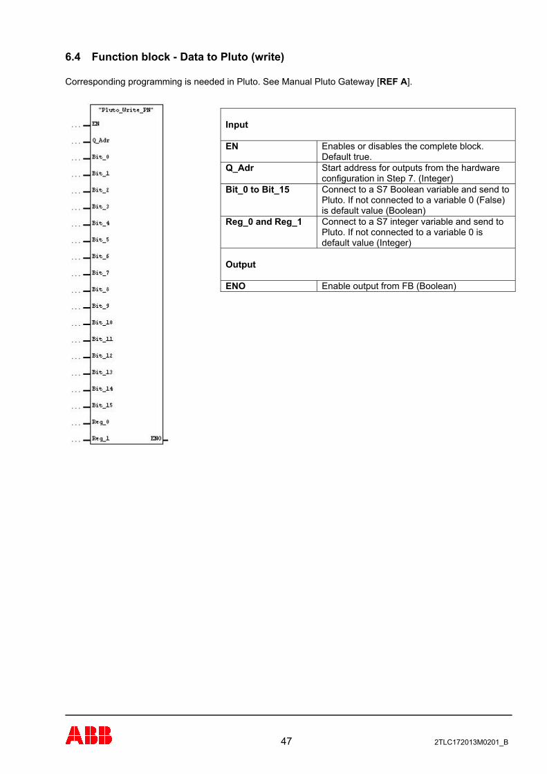
6.4 Function block - Data to Pluto (write) Corresponding programming is needed in Pluto. See Manual Pluto Gateway [REF A].
Input
Enables or disables the complete block. Default true.
EN
Start address for outputs from the hardware configuration in Step 7. (Integer)
Q_Adr
Connect to a S7 Boolean variable and send to Pluto. If not connected to a variable 0 (False) is default value (Boolean)
Bit_0 to Bit_15
Connect to a S7 integer variable and send to Pluto. If not connected to a variable 0 is default value (Integer)
Reg_0 and Reg_1
Output
Enable output from FB (Boolean) ENO
47 2TLC172013M0201_B
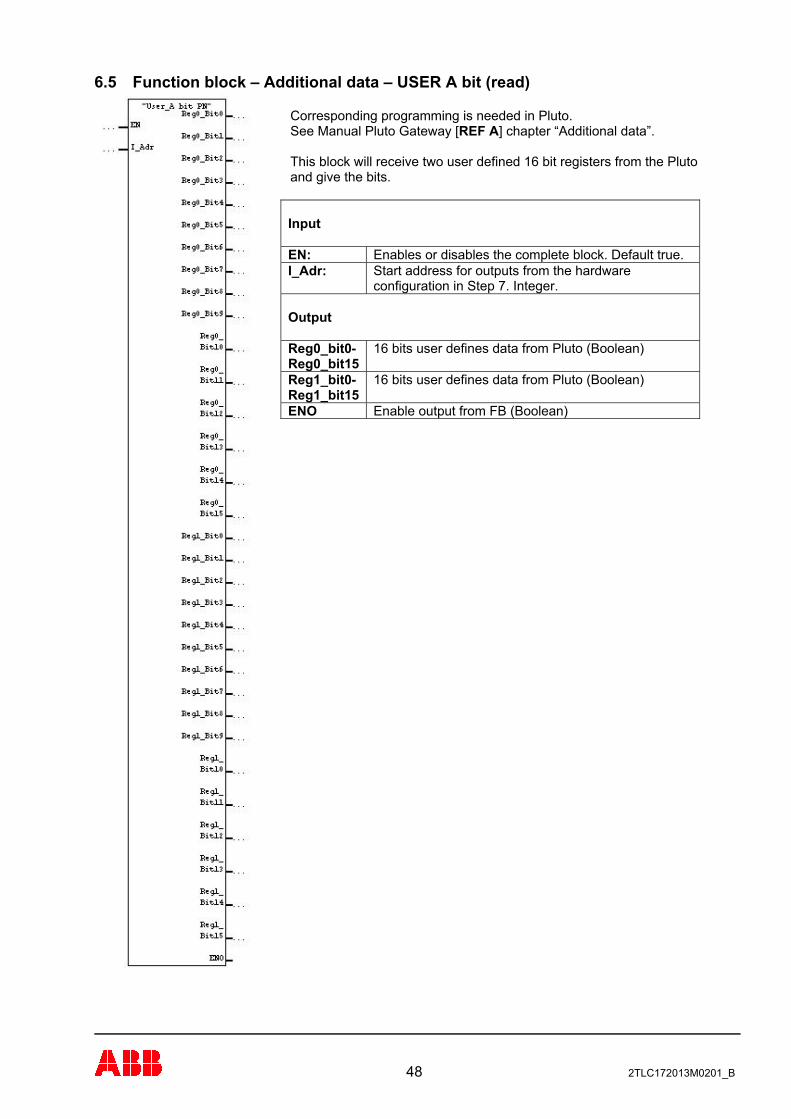
6.5 Function block – Additional data – USER A bit (read)
Corresponding programming is needed in Pluto. See Manual Pluto Gateway [REF A] chapter “Additional data”. This block will receive two user defined 16 bit registers from the Pluto and give the bits. Input
Enables or disables the complete block. Default true. EN: Start address for outputs from the hardware configuration in Step 7. Integer.
I_Adr:
Output
16 bits user defines data from Pluto (Boolean) Reg0_bit0- Reg0_bit15
16 bits user defines data from Pluto (Boolean) Reg1_bit0- Reg1_bit15
Enable output from FB (Boolean) ENO
48 2TLC172013M0201_B
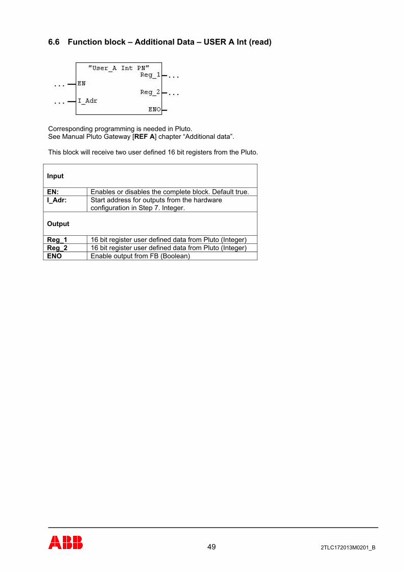
6.6 Function block – Additional Data – USER A Int (read)
Corresponding programming is needed in Pluto. See Manual Pluto Gateway [REF A] chapter “Additional data”. This block will receive two user defined 16 bit registers from the Pluto. Input EN: Enables or disables the complete block. Default true. I_Adr: Start address for outputs from the hardware
configuration in Step 7. Integer. Output Reg_1 16 bit register user defined data from Pluto (Integer) Reg_2 16 bit register user defined data from Pluto (Integer) ENO Enable output from FB (Boolean)
49 2TLC172013M0201_B
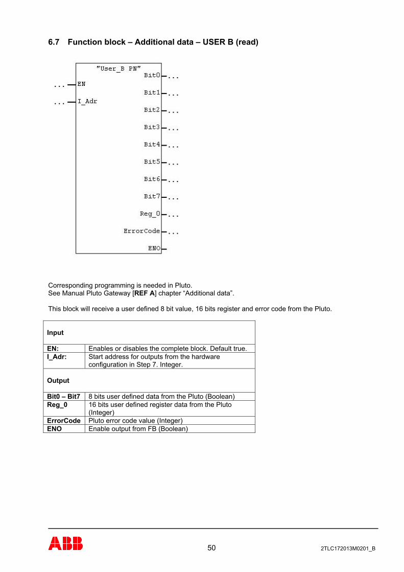
6.7 Function block – Additional data – USER B (read)
Corresponding programming is needed in Pluto. See Manual Pluto Gateway [REF A] chapter “Additional data”. This block will receive a user defined 8 bit value, 16 bits register and error code from the Pluto. Input EN: Enables or disables the complete block. Default true. I_Adr: Start address for outputs from the hardware
configuration in Step 7. Integer. Output Bit0 – Bit7 8 bits user defined data from the Pluto (Boolean) Reg_0 16 bits user defined register data from the Pluto
(Integer) ErrorCode Pluto error code value (Integer) ENO Enable output from FB (Boolean)
50 2TLC172013M0201_B
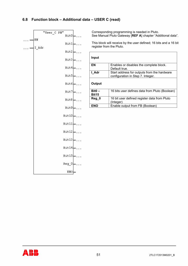
6.8 Function block – Additional data – USER C (read)
Corresponding programming is needed in Pluto. See Manual Pluto Gateway [REF A] chapter “Additional data”. This block will receive by the user defined; 16 bits and a 16 bit register from the Pluto. Input
Enables or disables the complete block. Default true.
EN
Start address for outputs from the hardware configuration in Step 7. Integer.
I_Adr
Output
16 bits user defines data from Pluto (Boolean) Bit0 – Bit15
16 bit user defined register data from Pluto (Integer)
Reg_0
Enable output from FB (Boolean) ENO
51 2TLC172013M0201_B
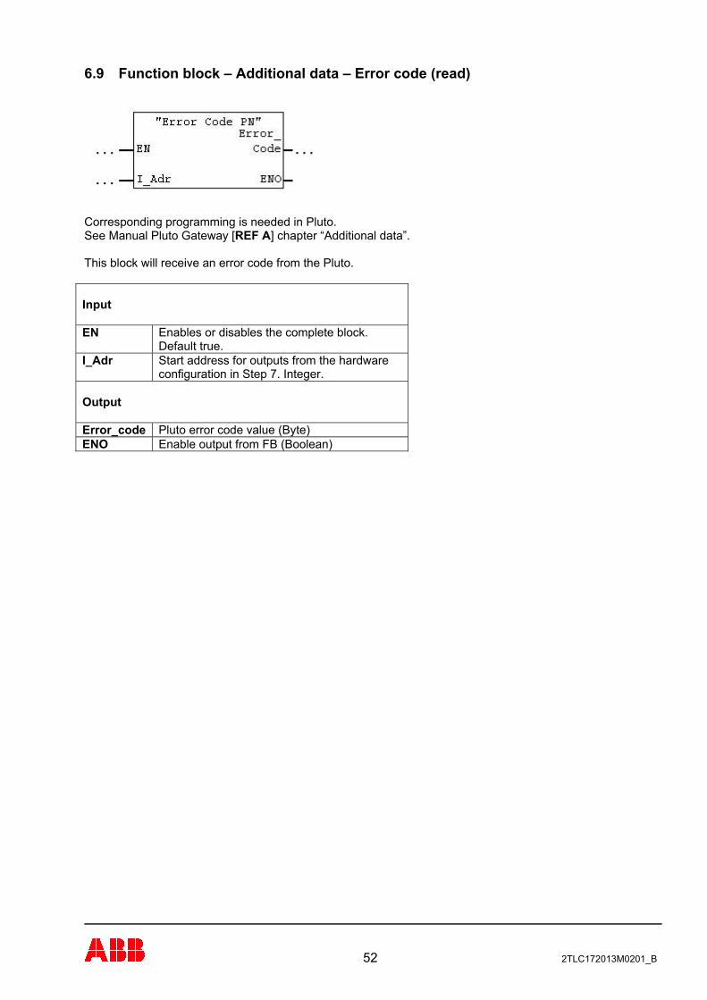
6.9 Function block – Additional data – Error code (read)
Corresponding programming is needed in Pluto. See Manual Pluto Gateway [REF A] chapter “Additional data”. This block will receive an error code from the Pluto. Input EN Enables or disables the complete block.
Default true. I_Adr Start address for outputs from the hardware
configuration in Step 7. Integer. Output Error_code Pluto error code value (Byte) ENO Enable output from FB (Boolean)
52 2TLC172013M0201_B
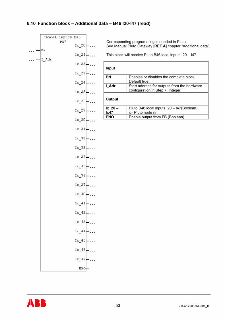
6.10 Function block – Additional data – B46 I20-I47 (read)
Corresponding programming is needed in Pluto. See Manual Pluto Gateway [REF A] chapter “Additional data”. This block will receive Pluto B46 local inputs I20 – I47. Input
Enables or disables the complete block. Default true.
EN
Start address for outputs from the hardware configuration in Step 7. Integer.
I_Adr
Output
Pluto B46 local inputs I20 – I47(Boolean), x= Pluto node nr.
Ix_20 – Ix47
Enable output from FB (Boolean) ENO
53 2TLC172013M0201_B
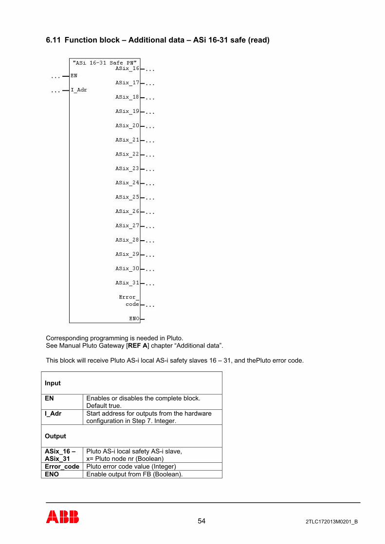
6.11 Function block – Additional data – ASi 16-31 safe (read)
Corresponding programming is needed in Pluto. See Manual Pluto Gateway [REF A] chapter “Additional data”. This block will receive Pluto AS-i local AS-i safety slaves 16 – 31, and thePluto error code. Input EN Enables or disables the complete block.
Default true. I_Adr Start address for outputs from the hardware
configuration in Step 7. Integer. Output ASix_16 – ASix_31
Pluto AS-i local safety AS-i slave, x= Pluto node nr (Boolean)
Error_code Pluto error code value (Integer) ENO Enable output from FB (Boolean).
54 2TLC172013M0201_B
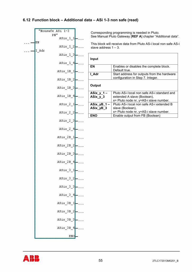
6.12 Function block – Additional data – ASi 1-3 non safe (read)
Corresponding programming is needed in Pluto. See Manual Pluto Gateway [REF A] chapter “Additional data”. This block will receive data from Pluto AS-i local non safe AS-i slave address 1 – 3. Input
Enables or disables the complete block. Default true.
EN
Start address for outputs from the hardware configuration in Step 7. Integer.
I_Adr
Output
Pluto AS-i local non safe AS-i standard and extended A slave (Boolean), x= Pluto node nr, y=AS-i slave number.
ASix_y_1 – ASix_y_3
Pluto AS-i local non safe AS-i extended B slave (Boolean), x= Pluto node nr, y=AS-i slave number.
ASix_yB_1 – ASix_yB_3
Enable output from FB (Boolean) ENO
55 2TLC172013M0201_B
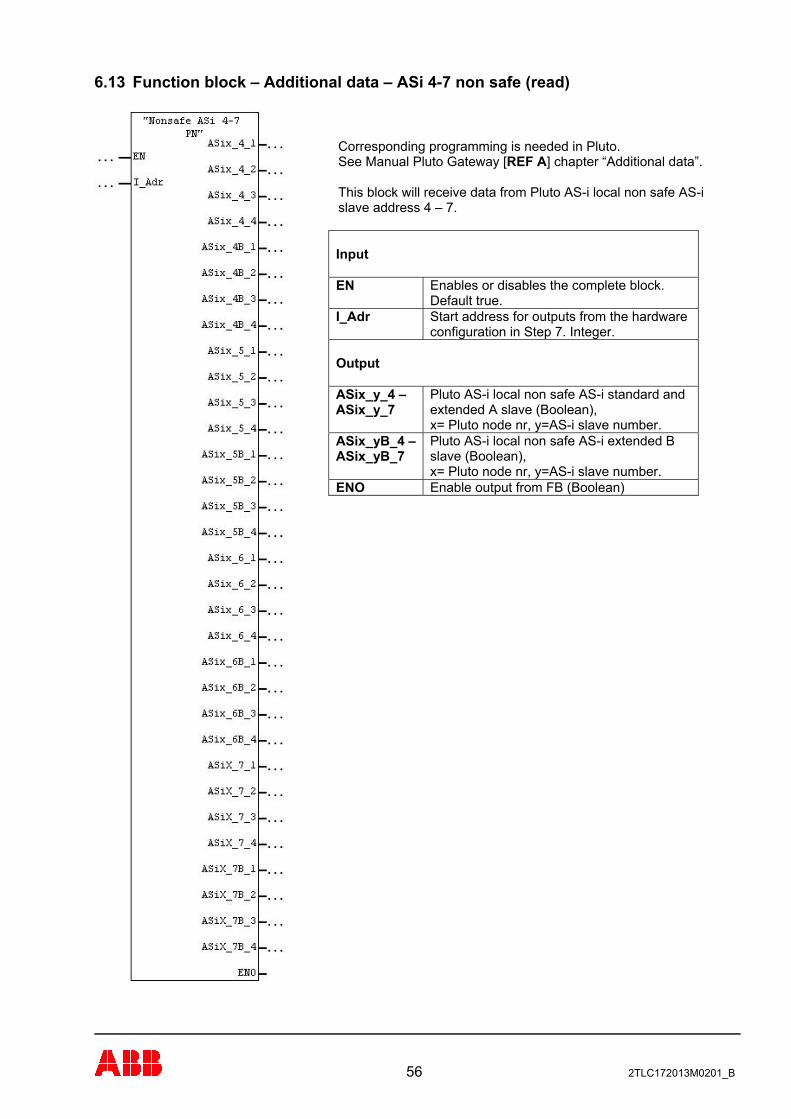
6.13 Function block – Additional data – ASi 4-7 non safe (read)
Corresponding programming is needed in Pluto. See Manual Pluto Gateway [REF A] chapter “Additional data”. This block will receive data from Pluto AS-i local non safe AS-i slave address 4 – 7. Input
Enables or disables the complete block. Default true.
EN
Start address for outputs from the hardware configuration in Step 7. Integer.
I_Adr
Output
Pluto AS-i local non safe AS-i standard and extended A slave (Boolean), x= Pluto node nr, y=AS-i slave number.
ASix_y_4 – ASix_y_7
Pluto AS-i local non safe AS-i extended B slave (Boolean), x= Pluto node nr, y=AS-i slave number.
ASix_yB_4 – ASix_yB_7
Enable output from FB (Boolean) ENO
56 2TLC172013M0201_B
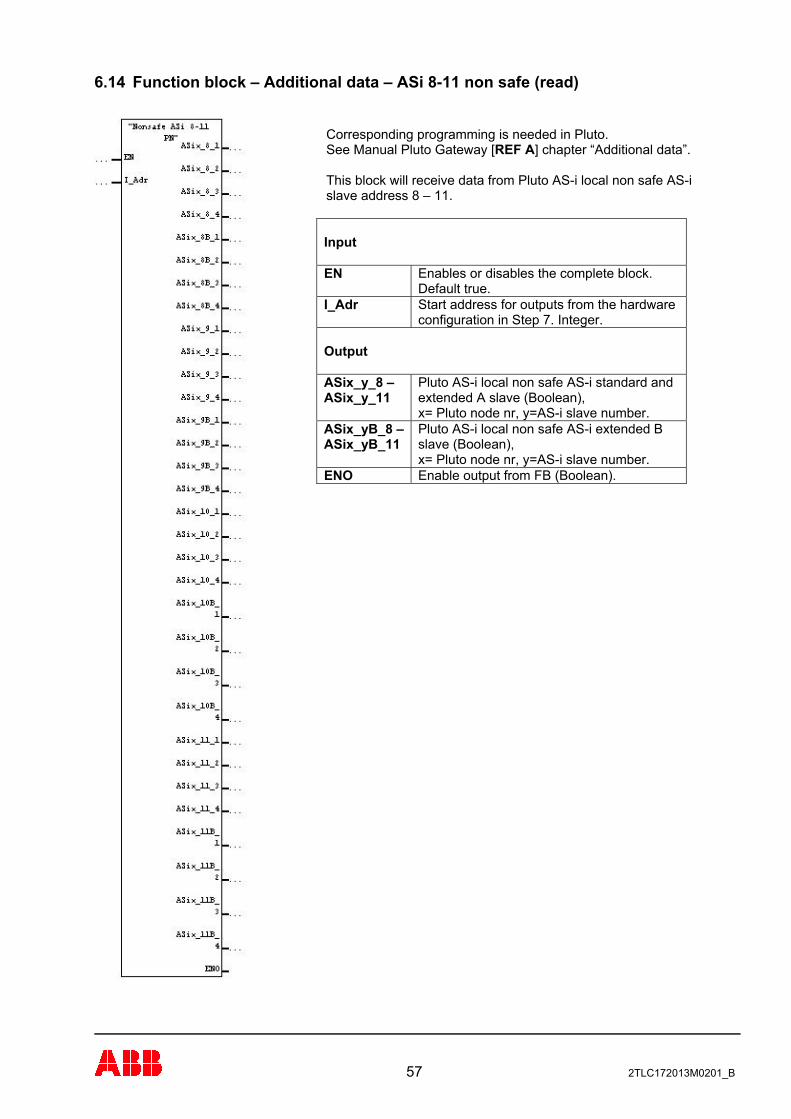
6.14 Function block – Additional data – ASi 8-11 non safe (read)
Corresponding programming is needed in Pluto. See Manual Pluto Gateway [REF A] chapter “Additional data”. This block will receive data from Pluto AS-i local non safe AS-i slave address 8 – 11. Input
Enables or disables the complete block. Default true.
EN
Start address for outputs from the hardware configuration in Step 7. Integer.
I_Adr
Output
Pluto AS-i local non safe AS-i standard and extended A slave (Boolean), x= Pluto node nr, y=AS-i slave number.
ASix_y_8 – ASix_y_11
Pluto AS-i local non safe AS-i extended B slave (Boolean), x= Pluto node nr, y=AS-i slave number.
ASix_yB_8 – ASix_yB_11
Enable output from FB (Boolean). ENO
57 2TLC172013M0201_B
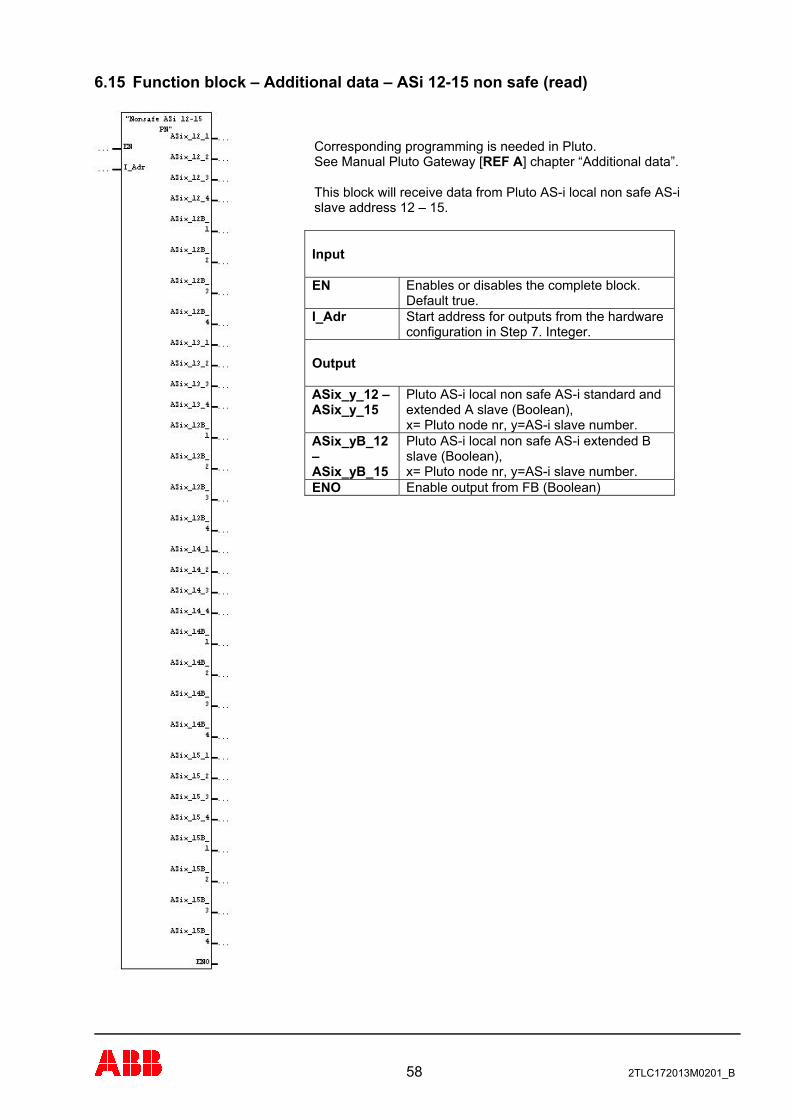
6.15 Function block – Additional data – ASi 12-15 non safe (read)
Corresponding programming is needed in Pluto. See Manual Pluto Gateway [REF A] chapter “Additional data”. This block will receive data from Pluto AS-i local non safe AS-i slave address 12 – 15. Input
Enables or disables the complete block. Default true.
EN
Start address for outputs from the hardware configuration in Step 7. Integer.
I_Adr
Output
Pluto AS-i local non safe AS-i standard and extended A slave (Boolean), x= Pluto node nr, y=AS-i slave number.
ASix_y_12 – ASix_y_15
Pluto AS-i local non safe AS-i extended B slave (Boolean), x= Pluto node nr, y=AS-i slave number.
ASix_yB_12 – ASix_yB_15
Enable output from FB (Boolean) ENO
58 2TLC172013M0201_B
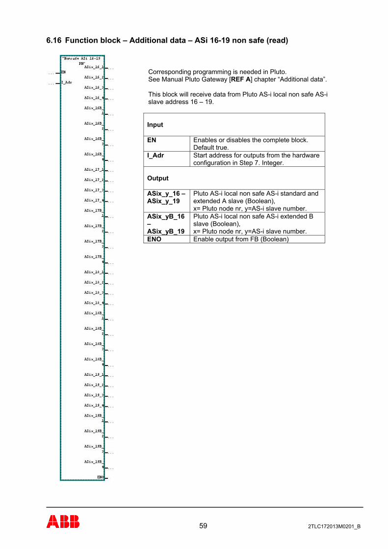
6.16 Function block – Additional data – ASi 16-19 non safe (read)
Corresponding programming is needed in Pluto. See Manual Pluto Gateway [REF A] chapter “Additional data”. This block will receive data from Pluto AS-i local non safe AS-i slave address 16 – 19. Input
Enables or disables the complete block. Default true.
EN
Start address for outputs from the hardware configuration in Step 7. Integer.
I_Adr
Output
Pluto AS-i local non safe AS-i standard and extended A slave (Boolean), x= Pluto node nr, y=AS-i slave number.
ASix_y_16 – ASix_y_19
Pluto AS-i local non safe AS-i extended B slave (Boolean), x= Pluto node nr, y=AS-i slave number.
ASix_yB_16 – ASix_yB_19
Enable output from FB (Boolean) ENO
59 2TLC172013M0201_B

6.17 Function block – Additional data – ASi 20-23 non safe (read)
Corresponding programming is needed in Pluto. See Manual Pluto Gateway [REF A] chapter “Additional data”. This block will receive data from Pluto AS-i local non safe AS-i slave address 20 – 23. Input
Enables or disables the complete block. Default true.
EN
Start address for outputs from the hardware configuration in Step 7. Integer.
I_Adr
Output
Pluto AS-i local non safe AS-i standard and extended A slave (Boolean), x= Pluto node nr, y=AS-i slave number.
ASix_y_20 – ASix_y_23
Pluto AS-i local non safe AS-i extended B slave (Boolean), x= Pluto node nr, y=AS-i slave number.
ASix_yB_20 – ASix_yB_23
Enable output from FB (Boolean) ENO
60 2TLC172013M0201_B
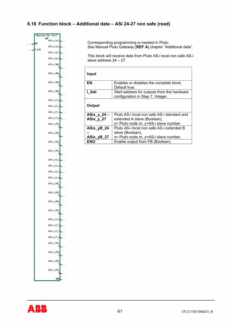
6.18 Function block – Additional data – ASi 24-27 non safe (read)
Corresponding programming is needed in Pluto. See Manual Pluto Gateway [REF A] chapter “Additional data”. This block will receive data from Pluto AS-i local non safe AS-i slave address 24 – 27. Input
Enables or disables the complete block. Default true.
EN
Start address for outputs from the hardware configuration in Step 7. Integer.
I_Adr
Output
Pluto AS-i local non safe AS-i standard and extended A slave (Boolean), x= Pluto node nr, y=AS-i slave number.
ASix_y_24 – ASix_y_27
Pluto AS-i local non safe AS-i extended B slave (Boolean), x= Pluto node nr, y=AS-i slave number.
ASix_yB_24 – ASix_yB_27
Enable output from FB (Boolean). ENO
61 2TLC172013M0201_B
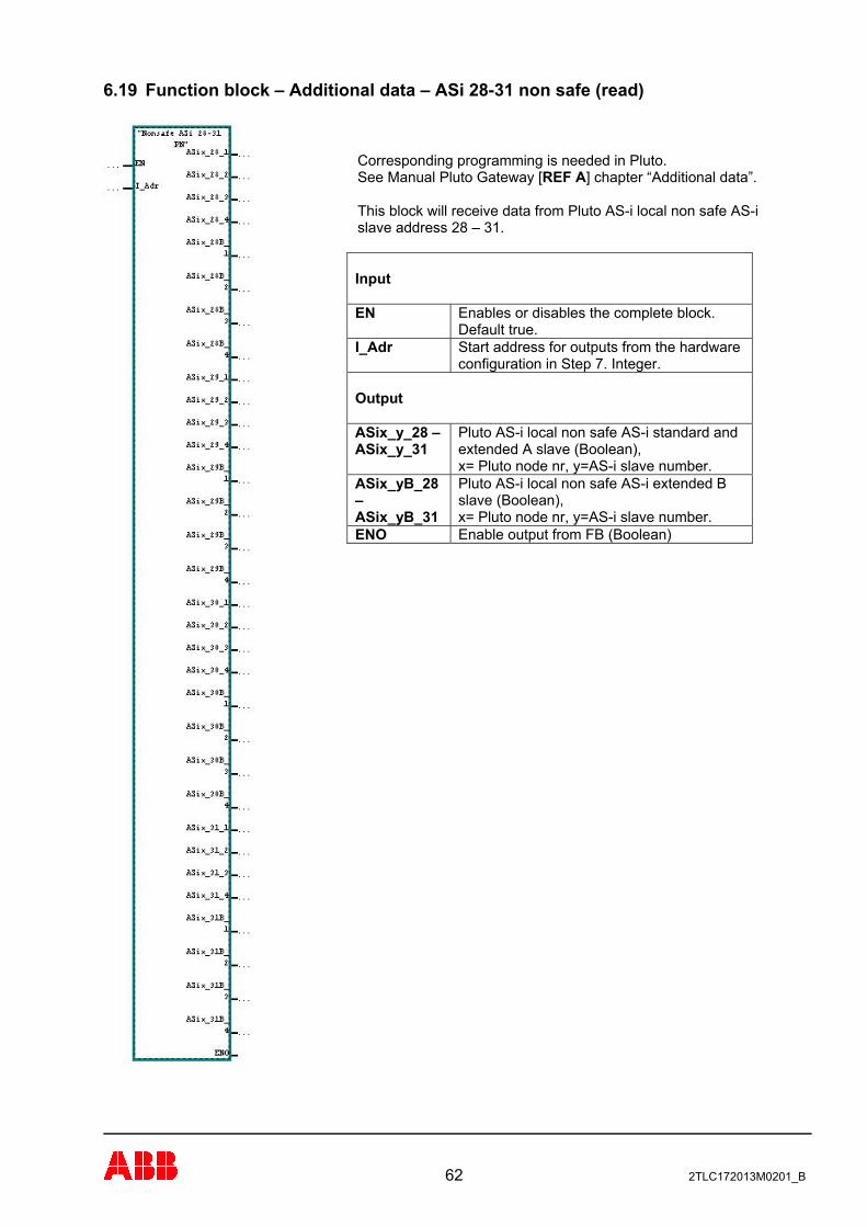
6.19 Function block – Additional data – ASi 28-31 non safe (read)
Corresponding programming is needed in Pluto. See Manual Pluto Gateway [REF A] chapter “Additional data”. This block will receive data from Pluto AS-i local non safe AS-i slave address 28 – 31. Input
Enables or disables the complete block. Default true.
EN
Start address for outputs from the hardware configuration in Step 7. Integer.
I_Adr
Output
Pluto AS-i local non safe AS-i standard and extended A slave (Boolean), x= Pluto node nr, y=AS-i slave number.
ASix_y_28 – ASix_y_31
Pluto AS-i local non safe AS-i extended B slave (Boolean), x= Pluto node nr, y=AS-i slave number.
ASix_yB_28 – ASix_yB_31
Enable output from FB (Boolean) ENO
62 2TLC172013M0201_B