plc implementation of beverage routing control …...plc implementation of beverage routing control...
TRANSCRIPT

PLC IMPLEMENTATION OF BEVERAGE ROUTING CONTROL
ALGORITHM
ANUSHA YERROJU
Bachelor of Electrical Engineering
Jawaharlal Nehru Technological University
April, 2005
submitted in partial fulfillment of requirements for the degree
MASTER OF SCIENCE IN ELECTRICAL ENGINEERING
at the
CLEVELAND STATE UNIVERSITY
August, 2007

This thesis has been approved
for the Department of Electrical and Computer Engineering
and the College of Graduate Studies by
________________________________________________
Thesis Committee Chairperson, Dr. Lili Dong
________________________________
Department/Date
________________________________________________
Dr. Pong P. Chu
________________________________
Department/Date
________________________________________________
Dr. Wenbing Zhao
________________________________
Department/Date

ACKNOWLEDGEMENT
I deeply thank and acknowledge my advisor Dr. Lili Dong who has been a
constant source of motivation and inspiration. I express my sincere gratitude for her time
and efforts.
I thank my committee members Dr. Wenbing Zhao and Dr. Pong P. Chu for their
time and guidance amidst their busy schedules, to successfully complete my thesis.
I express my sincere gratitude to my advisor and mentor Dr. Raymond J. Staron at
Rockwell Automation, whose keystone guidance and support helped me develop the
algorithm successfully. I acknowledge my program manager at Rockwell Automation,
Dan L. Carnahan for providing the great opportunity to work with them in Advanced
Technology department at Rockwell Automation as a Co-op.
I am indebted to my parents for their boundless love and sacrifice, my sister,
brother and cousin for their moral support. I thank my friends for their encouragement
and intellectual input during the complete course of thesis.

iv
PLC IMPLEMENTATION OF BEVERAGE ROUTING
CONTROL ALGORITHM
ANUSHA YERROJU
ABSTRACT
Programmable logic controllers (PLCs) are the most popular and powerful
devices used in process control applications. A PLC-based structured routing algorithm
for controlling the operation of valves so as to route the requested material between any
two points in the respective beverage plant equipment is presented. The basic route
control algorithm considers several possible, practical constraints usually imposed on
beverage routing in the plant. A good routing algorithm adaptable with changes in the
process setup and implementable with minimum engineering efforts at the beverage
manufacturing site is the focus. The developed algorithm along with the software
environment in which it is run, should provide a flexible, easy to operate, user friendly,
adopting improvements and changes with less engineering efforts.
This thesis involves translating object oriented logic for route control to structure
oriented control logic. The structured algorithm is developed using the RSLogix5000™
software, a tool that supports the IEC 61131 standards for PLC programming. The
resulting program is verified and run in the Soft-controllerTM software of Rockwell
Automation’s Logix™ family of controllers. The structured algorithm developed focuses
on beverage industry. The algorithm is programmed and implemented in already existing
controllers which will avoid any firmware modifications required to support the new
algorithm. This will lead to economic solution for both beverage industries and controller
developers. The focus of this work is on translating the objects into structures and
develop route control algorithm which can be implemented in existing PLC.

v
TABLE OF CONTENTS
Page
LIST OF TABLES........................................................................................................ VII
LIST OF FIGURES .....................................................................................................VIII
I INTRODUCTION....................................................................................................... 1
1.1 Literature Review........................................................................................ 3
1.2 Thesis Organization .................................................................................... 6
II PROBLEM FORMULATION .................................................................................. 7
2.1 Introduction to the Problem ........................................................................ 7
2.2 Problem Definition………………………………………………………...8
III INTRODUCTION TO PROGRAMMABLE LOGIC CONTROLLER ............ 16
3.1 PLC-Architecture, Operation and Programming ...................................... 18
3.2 Ladder Logic and Structured Text Languages…………………………...22
IV VALIDATION PLATFORM - SOFTLOGIX AND RSLOGIX5000… …………25
4.1 SoftLogix Controller..................................................................................25
4.2 RSLogix5000 ............................................................................................ 28
V STRUCTURES, PROGRAM FLOW AND LOGIC OF ROUTING
ALGORITHM…………………………………………………………………………..30
5.1 Translation of Objects to Structures……………………………………..30

vi
5.2 Data Structures and Data Members……………………………………...35
5.3 Introduction to Algorithm………………………………………………..37
VI SIMULATION RESULTS OF ROUTE CONTROL ALGORITHM… ……….44
6.1 Route - Valves and Constraints…………………………………………. 48
VII CONCLUSION AND FUTUREWORK ................................................................ 54
REFERENCES................................................................................................................ 58

vii
LIST OF TABLES
Table Page
TABLE I: Basic Functions in the Program flow…………………………………….43

viii
LIST OF FIGURES
Figure Page
Figure 1: Valve, Pipes and External Connections.................................................... 10
Figure 2: Multiple Valve Matrices ........................................................................... 11
Figure 3: Object Oriented Concept........................................................................... 12
Figure 4: Valve Matrix ............................................................................................ 13
Figure 5: Schematic View of the User Interface Setup in the Plant......................... 14
Figure 6: Examples of PLCs in the Market ..............................................................16
Figure 7: Architecture of PLC.................................................................................. 19
Figure 8: Operation of PLC...................................................................................... 20
Figure 9: SoftLogix Window.................................................................................... 26
Figure 10: SoftLogix Chassis Monitor ....................................................................... 27
Figure 11: Data Structure – Valve.............................................................................. 31
Figure 12: Data Structure - Path............................................................................... 302
Figure 13: Data Structure Valve Matrix................................................................... 302
Figure 14: Data Structure – Valve Proposal Record .................................................. 33
Figure 15: Data Structure – Valve Usage Record ...................................................... 34
Figure 16: Data Structures in Controller Memory (i)................................................. 35

ix
Figure 17: Data Structures in Controller Memory (ii)……………………………….36
Figure 18: Hierarchical View of Functions in Algorithm .......................................... 38
Figure 19: Different Types of Functions in Algorithm .............................................. 39
Figure 20: Program Flow of Algorithm...................................................................... 40
Figure 21: Data Structure – Path Request .................................................................. 41
Figure 22: Data Structure – toDoIterations ................................................................ 42
Figure 23: Valve Matrix ..............................................................................................45
Figure 24: ....... Data Structure – PathRequest……………………………………………46
Figure 25: Data Structure - Paths Listed .................................................................... 47
Figure 26: Routes Expected........................................................................................ 47
Figure 27: Data Structure - Path................................................................................. 49
Figure 28: One possible route for the given request...................................................50
Figure 29: Valve Proposal Records………………………………………………….51
Figure 30: Directions………………………………………………………………...52
Figure 31: Directions of the flow in sample route...................................................... 53

1
CHAPTER I
INTRODUCTION
In a beverage industry, there are several ingredients to manufacture a product. The
materials are stored at various locations in the plant. These materials are to be carefully
routed between different points of the plant equipment as a part of beverage
manufacturing process. They are required to flow through different pipes depending on
the process. All the fixed pipes in a plant for material routing have valves at the
intersection points of pipes. To set a path through these pipes for a material flow between
any two points, respective valves in the path should be operated (closed or opened) in
desired manner, depending on the kind of process employed at that point of time.
The task of controlling the operation of valves can be simple if the control is
limited to one or two paths. Manual resources would be sufficient to achieve route
control. One cannot deny the fact that the same manual resources would be of not much
help when multiple materials and multiple paths are to be controlled simultaneously.
Optimum usage of resources including labor, machinery, money, materials is critical to
any beverage industry while the main goals is to meet excellent quality standards thus to
meet the expectations of customers and market demands.

2
Automation principles are substantially developed to aid process control for
several industrial applications. Programmable logic controllers help us develop solutions
for route control problems. Several routing algorithms are popular in the market for
efficient routing in beverage industry.
This thesis is a result of successful attempts made to come up with a
commercially viable control algorithm for material routing. The algorithm developed
focuses on beverage industry. A good routing algorithm should be adaptable without
major changes in the process setup and minimum engineering efforts during
implementation at the beverage manufacturing site. It should be easily loaded into the
RAM of the controller and easily implemented in any existing controller, which avoids
any firmware modifications required to support the new algorithm. The developed
algorithm along with the software environment in which it is run should provide a
flexible, user friendly, capable of adopting improvements and changes with less
engineering efforts. This will lead to economic solution for both beverage industries and
controller developers. The subject of this thesis is developing such a control algorithm.
Some of the popular route control algorithms will be introduced to help us with some
background knowledge on this subject. The algorithm in this thesis is developed in
RSLogix5000 and the developed code is run in SoftLogix controller. The main function
of the algorithm is to generate routes when a user or operator requests. The algorithm is
implemented on PLC.

3
1.1 Literature Review
The route control solutions provided by different companies are summarized as
follows [5].
1.1.1 Competitive Offerings
1. Siemens Route Control Module: This is a very sophisticated path selection
module developed by Siemens. Route control encompasses the feature of both
project engineering and the run time system. The algorithm also provides many
interfaces to the PCS 7 basic system. Simple transport processes and large number
of complex route combinations are the advantages. This module was considered
to be the premier solution on the market but has drawbacks of being complex and
requires considerable engineering efforts to implement.
2 Proleit: The solution developed by Proleit is basically a matrix path selection
which provides both pre-configured paths and dynamic selection to some extent
based on the path parameters. The module which is called Route Equipment
Module enables fully automatic route control.
3 Rockwell Automation solutions: There are multiple solutions offered by Rockwell
services, that include many significant features in the algorithm that accounts for
recipe type, route part, design, allocate, actuate and monitor valves, selecting and
4
evaluating route part availability(allocated or free), mode(automatic or manual),
and status(dirty, ready etc).
1.1.2 Deficiencies in Current Solutions
The routing algorithms discussed have certain deficiencies in their design. The
following are the limitations of the routing algorithms.
• Solution consists of specific code for various route parts and hence lacks
the reusability feature when location of the active site in the plant is
changed. Several recipes are to be considered in preparation
simultaneously using the same plant as it requires a specialist who is
aware of recipe techniques for implementing the solution tool developed
as in the case of solution provided to customer which is major beer
producer.
• Since every path transfer is being uniquely defined as a configuration,
there can be impracticality while implementing the technique. There will
be a large number of configurations or a combination of routes which
poses difficulty at the time of implementation in case of increased number
of sources and destination containers or tanks as in the case of Rockwell
IAS-MTM.
• Solution is confined to pre-computed paths, making the routes not
reusable at most times. The system also needs route selection scheduling
well in advance as in the case of the solution, Heineken Selector.

5
Heineken Selector is also a route control solution for the beverage
company, Heineken.
• Sequencing of valve patterns in a valve matrix poses difficulty as in the
case of Rockwell IAS-VMM.
• Lack of dynamic route selection between two points of the process as in
the RS Bizware batch.
Most of the solutions have all the possible routes pre-programmed into the
controller or computer. When a route request is made by the user or operator, the
controller algorithm generates best available route. The selection of the best possible
route depends on the various constraints imposed. The constraints vary with the
variations of the type of the product being manufactured, condition of valves and the
user’s choice.
Unlike the algorithm developed in the present work, these solutions are mostly
implemented in computer based controllers which require extra maintenance due to
industry environment where they are installed. Thus we can see that route control
algorithm when implemented in a programmable logic controller rather than general
computer needs less maintenance, less memory space and has greater flexibility in
selecting the routes.
The proposed solution overcomes most of the above mentioned limitations by
dynamic computation of the route. The routing algorithm developed as part of this thesis
can be completely programmed into the memory of the programmable logic controller as
desired. The programmable logic controller can withstand severe industrial conditions

6
and is more reliable than a computer. Dynamic routing saves required memory since not
all routes are stored in the memory (RAM) but only those generated for particular path
request needs to be stored till the completion of route execution. Details regarding the
algorithm are explained in the following chapters.
1.2 Thesis Organization
The thesis is organized as follows. Chapter 2 presents the basic idea of proposed
solution to the routing problem. Chapter 3 provides sufficient information about the
programmable logic controllers, their architecture, memory specifications, and
programming languages used in developing the routing algorithm. Chapter 4 deals with
the software tools employed to program and execute the algorithm. A brief description of
program flow, algorithm and a detailed description of methodology in transferring object
oriented concept into structure oriented format are explained in chapter 5. The results are
presented in chapter 6. The scope for further improvements and other features are given
in chapter 7.

7
CHAPTER II
PROBLEM FORMULATION
This chapter introduces the routing control problem in a detail. Review of the
currently available routing solutions and their limitations is given. The desired features
for the new algorithm are defined.
2.1 Introduction to the Problem
The solutions available in the market do not support dynamic computing of
routes. They either have the route control which stores the predefined routes statically in
controller memory depending on several other path parameters or provides incomplete
dynamic computation and allocation. The main goal of this thesis is to dynamically
compute various paths and select the best path based on the length of path, recipe, least
number of valves or other user defined constraints for material flow every time a request
is put in.

8
Material flow is dependent on various parameters such as the number of available
valves available, pipes in working condition, source container, and destination container
etc. The primary requirement in achieving the solution for the defined problem is to
successfully translate object oriented concept into structured algorithm. This is the crux
of the thesis, as it depends on the software, architecture of the controller, memory
specifications, and programming language constraints etc. The object oriented algorithm
while implemented in the controller requires several firmware modifications in the
controller which is not commercially viable. Hence an algorithm has to be developed
using a language supported by already existing controller.
2.2 Problem Definition
The fundamentals of the valves and the features of the routing algorithm will be
discussed before we define the problem and the planned solution. The terms used in the
routing algorithm for the beverage industry are defined as follows.
• Route: The possible path through which the material can flow from its
source container to destination container.
• Routing: Assigning the correct path for a fluid to flow into destination
container.
• Valve: A Structure that gives access to all the valves and its positioning in
the valve matrix.

9
• Valve Matrix : Valve matrix is a collection of valves placed in rows and
columns along with source and destination points as its elements.
• Path Selector: A function that selects the best path between given source
and destination upon request.
• Valve usage Record: Valve usage record allows updating all the
information on the recently used valves with time, material flow through
the valve, the starting and the ending points.
• Valve Proposal Record: Valve proposal record provides information
about the next valve in the path to be considered, with its position
coordinates or its position identifier, along with starting and ending points.
• Current Activities : Current activities give information about the present
status of routing equipment in the form of a data table.
A matrix with all the valves as its elements is identified by a variable for the
problem analysis. The valves in the matrix are considered to be interconnected in every
row and column through mazes of pipes. Source and destination points for the flow of the
beverage are shown as square boxes in Figure 1. They are connected externally to the
valve matrix. In a beverage industry, a large number of such valve matrices are
interconnected. The valve matrices are located in the same level or different levels, near
to or far away from one another depending on the plant construction.
A single valve can be in two states depending on the direction of the flow of the
material across the valve. When a valve is in closed state, the horizontal and vertical

10
pipes are separated at the point of intersection. Different materials can flow across them
independently without interfering with one another. Path p2 shows flow across closed
valve whose source is in row 2, column 0. When the valve is said to be open, the material
flow can change direction. A sample path across an open valve is shown as p3 and p1. In
p3 the valve in row 3 and column 3 is open to participate in the path whose source is in
row 3, column 0 and destination is in row 0, column 3. Similarly in p1, valve in row 1
and column 5 is open.
Figure 1 Valve, Pipes and External Connections
In real applications there is more than a single valve matrix. Beverages need to be
routed between several matrices. These matrices will be interconnected based on the

11
plant infrastructure, type of beverages being manufactured and complexity involved in
manufacturing procedure or routing process etc. A sample view of multiple matrix
structures is shown in Figure 2.
Figure 2 Multiple Valve Matrices

12
In the Figure 2 we can see three valve matrices are connected to each other. A
user request may involve beverage routing in a single valve matrix or across two or more
valve matrices.
An object oriented algorithm was developed to dynamically compute and control
the routes. As mentioned earlier, the developed solution should be implemented in
existing controllers. The object oriented algorithm which was previously developed when
implemented in the controller demands some firmware modifications. Hence a structure
oriented algorithm has to be developed that can be implemented in the existing controller.
The five objects developed in object oriented algorithm to achieve dynamic routing are
shown in Figure 3.
Figure 3 Object Oriented Concept

13
The complete algorithm was developed using these five objects. Valve Matrix, valve
and path are the basic objects that relate to the information such as number of valves,
coordinates of valves, valves in a particular path, material to be routed, and the source
and the destination. Valve Usage Record and Valve Proposal Record are the objects
that contain the information related to state of the valve in an executing path and
proposed path respectively as can be understood by their names. This concept now
has to be translated to structures and the algorithm has to be developed using the
structures that will dynamically compute the routes between requested source and
destination. An example matrix with three external connections has been used in the
process of algorithm development. This example matrix has nine valves distributed in
3 rows and 3 columns. Our problem is translating these five major objects into
structures i.e., developing a structure oriented algorithm that will compute all possible
routes between any two given points of the three external connections.
Figure 4 Valve Matrix

14
A three by three matrix with three possible inputs/outputs is shown in Figure 4.In
Figure 4 dots represent the nine valves. Pipes are the straight lines inside the matrix. The
three straight lines shown outside the valve matrix indicate external connections. These
are the locations where beverage enters or leaves a valve matrix when routed.
At high level, the problem can be understood as shown in figure 5. The controller
is programmed and installed in the plant. There is also user interface from which the
operator can communicate to the controller in order to control the process. The controller
is also connected to sensors and actuators.
Figure 5 Schematic View of the User Interface Setup in the Plant
15
These sensors in turn feedback the valve position/condition to the controller and
actuators send signals that will operate the valves. An algorithm should be developed to
compute routes dynamically using the information of position /condition of the valves.
It should take into consideration if the valve is already in use, in repair condition,
constrained to be in a specific state for some other already executing routes etc. A user
interface tool can help the operator put request, access the possible routes on the screen,
to give command in order to execute a route, and also obtain some graphical images or
animations.
These graphical images or animations may show the operator routes presently in
execution, flow of the material, and valves in operation etc. Figure 5 gives us a better
idea of how the controller is installed and used in a beverage plant.
The limitations of programming languages used to develop the algorithm also
form one of the issues stated in problem definition. The Structured Text language
supported by RSLogix5000, the tool used in this work, does not have pointers and
consists of very simple statements to define functions and logic. Developing a route
control algorithm applicable to real world application using simple programming
language like Structured Text language is surely not an easy task. The algorithm should
accommodate many complex features.

16
CHAPTER III
INTRODUCTION TO PROGRAMMABLE LOGIC CONTROLLER
In this chapter, a brief description of Programmable Logic Controllers is
presented. To control machinery and automate industrial processes, programmable logic
controllers are the efficient electronic devices. They support multiple inputs and output
and withstand varied temperatures, industrial noise, vibration etc [8].
Figure 6 Examples of PLCs in the Market

17
The programmable logic controller was originally invented by Allen-Bradley.
The term "PLC" was trademarked by Allen-Bradley, and subsequently became
generically used by the automation and controls industry. Pictures of typical PLCs are
shown in the Figure 6.
“A plc can be defined as digitally operating electronic system, designed for use in
an industrial environment, which uses a programmable memory for the internal storage of
user-oriented instructions for implementing specific functions such as logic, sequencing,
timing, counting and arithmetic, to control, through digital or analogue inputs and
outputs, various types of machines or processes”[6]. Both the PLC and its associated
peripherals are designed so that they can be easily integrated into an industrial control
system and easily used in all their intended functions. Some of the popular PLC
companies are ABB Ltd, koyo, Honeywell, Siemens, Modicon, Omron, Allen-Bradley,
General electric and Mitsubishi [6].
The software revisions are helpful in eliminating the rewiring of hardwired
controls whenever the process is changed or new models are introduced. Relay control,
motion control, process control, networking and distributed control systems are some of
the functionalities of PLCs.
Programs with logic necessary to control the processes are downloaded into the
controller’s memory which is battery backed or non volatile. The PLC based control
system is a real time system since the outputs are responding to the inputs in bounded
time. The input and output arrangements of the PLC are connected to sensors and
actuators. PLCs connected with sensors to sense temperature, pressure, positions etc can
be efficiently used to process the data. They can operate electric motors, hydraulic

18
equipment, relays and many other electrical and mechanical devices. PLCs replace large
number of relays which were used for automation [8].
PLCs also include the logic for single-variable feedback analog control loop such
as a PID controller. The functionality of a programmable logic controller can be preferred
as well on a specific hardware and software platform as on a general purpose computer or
a personal computer with industrial environment features. PLCs, their application
programs and their associated peripherals are considered as components of a control
system.
An important component in the PLC control system is human-machine interface
(HMI) function. The HMI function has two purposes as follows.
• To provide the operator with the information necessary for monitoring the
operation of the machine/process.
• To allow the operator to interact with the PLC system and its application
program in order to make decisions and adjustments beyond their
individual user scope.
3.1 PLC –Architecture, Operation and Programming
3.1.1 Architecture
PLC mainly consists of CPU, memory areas, the circuits to receive inputs and
outputs, timers, counters, relays, and data storage locations. The PLC for machine control

19
takes inputs, give outputs signals according to the states of inputs and the outputs
generated through the software program [7]. The input circuits allow the PLC to receive
signals from outside. These signals can be feedback signals or input signals from user or
operator.
Figure 7 Architecture of PLC
It can be seen in Figure 7 CPU is the main component of the programmable logic
controller. The processor takes the input data and computes corresponding output data

20
according to the algorithm. The output circuit provides connections to display screens,
actuators etc. The program and necessary data are stored in the memory cells. Relays,
timers and counters play important role in instruction execution. Unlike relays, the inbuilt
timers and counters in a PLC make all arithmetic operations easy.
3.1.2 Operation of PLC
The algorithm running in the controller gives commands to the processor in the
controller to continually check the inputs [7]. When the expected inputs that trigger any
part of the logic are found the PLC executes the algorithm accordingly. After executing
the algorithm, the output data that is required to control the application is send to I/O
ports. The PLC updates the output status wherever required.
Figure 8 Operation of PLC

21
The operation of a PLC can be explained in the following three simple steps.
• Checks the inputs
• Executes the program
• Updates the output status
3.1.3 PLC Programming
For programming of the application, there is a set of languages defined in IEC
61131-3.
(a) Textual Languages
• Instruction List language: A textual programming language using
instructions for representing the application program for a plc-system [1].
• Structured text language: A textual programming language using
assignment, sub-program control, selection and iteration statements to
represent the application program for a plc system [1].
(b) Graphical Languages
• Function block diagram (FBD): FBD can be used to express the behavior
of functions, function blocks and programs as a set of interconnected
graphical blocks. It can also be used within the sequential function charts
to express the behavior of steps, actions and transitions [1].
• Ladder Diagram (LD): LD program enables the programmable controller
to test and modify data by means of standardized graphic symbols [1].
22
3.2 Ladder Logic and Structured Text Languages
To develop routing algorithm for beverage industry application, ladder diagram
and structured text programming languages have been used. The reasons for using these
two languages can be found in chapter 5. A brief description of these two programming
languages is given in this section.
3.2.1 Ladder Logic
Ladder Diagram has been developed by the IEC by considering the most
commonly used symbols and terminologies used in the mainstream PLCs. Ladder
diagram is based on a technique which uses relays to design logic. Ladder diagram has a
left hand vertical power rail that notionally supplies power through contacts spreading out
along horizontally connected rungs. Ladder diagram can be very effective at describing
digital logic in a form that is easy to program and understand. Ladder diagram is suitable
for expressing the behavior of parts of programs that are primarily concerned with
combinational logic [9].
Ladder logic is a graphical language used to draw electrical logic schematics.
PLCs use a language called relay ladder logic programming. In other common
programming languages such as FORTRAN or C, commands are executed in a sequential
order. The command or line of code on top is executed before the command on the
bottom until you hit the end of a loop. However, in ladder logic, every command in each
rung is executed simultaneously at the same time. Ladder logic is more like a flow chart
than a program. A PLC, like any microprocessor, executes a list of instructions in

23
sequence. Ladder logic tools abstract this. PLC can be programmed by wiring up relay
contacts and coils on-screen, and the PLC runtime software will simulate the circuit
drawn using ladder logic. Some of the relay contacts can be tied to input signals from the
real world, some of the coils can be tied to outputs. The simulated circuit in ladder logic
interacts with other devices and actually controls the flow [1].
Most manufacturers of programmable logic controllers also provide associated
ladder logic programming systems. Typically, the ladder logic languages from two
manufacturers will not be completely compatible. Ladder logic is better thought of as a
set of closely related programming languages rather than one language. Even different
models of programmable controller within the same family may have different ladder
notation such that programs cannot be seamlessly interchanged between models [2].
Ladder logic can be thought of as a rule-based language, rather than a procedural
language. A "rung" in the ladder represents a rule. When implemented with relays and
other electromechanical devices, the various rules "execute" simultaneously and
immediately. When implemented in a programmable logic controller, the rules are
typically executed sequentially by software, in a loop. By executing the loop faster,
simultaneous and immediate execution is obtained, similar to other rule-based languages
like spreadsheets and SQL. However, proper use of programmable controllers requires
understanding the limitations of the execution order of rungs [1].
3.2.2 Structured Text
Structured Text is a high level language which has a syntax that at first
appearance is similar to PASCAL. Although there are some minor similarities to

24
PASCAL, Structured Text is a distinct language that has been specifically developed for
industrial control applications [1].
The Structured Text language has a comprehensive range of constructs for
assigning values to variables, calling functions, function blocks, for creating expressions,
for conditional evaluation of selected statements and for iteration, i.e. repeating selected
sections of code. The language statements can be written in a fairly free style where tabs,
line feed characters and comments can be inserted anywhere between keywords and
identifiers, i.e. wherever a space character is required. It is a language that is easy to read
and understand, particularly when written using meaningful identifiers and well
annotated with comments [1].
Structured Text is a general purpose high-level language for expressing different
types of behavior involving a variety of different types of data. It is particularly useful for
complex arithmetic calculations. The IEC 1131-3 standard only defines Structured Text
as the language that consists of statements that can be used to assign values to variables,
for example, within function block and program bodies [1], [2].

25
CHAPTER IV
VALIDATION PLATFORM - SOFTLOGIX AND RSLOGIX5000
The routing algorithm was developed using RSLogix 5000 and run in
SoftLogix5800 of version 13. Both these software tools are products of Rockwell
Automation. To have a better understanding of the problem definition, algorithm, and
results, some very general information about RSLogix5000 and SoftLogix5800 is
included in this chapter.
4.1 SoftLogix Controller
SoftLogix5800 is a soft controller and comes from the category of programmable
automation controllers. The control functions written for the application are downloaded
into a programmable controller. The SoftLogix controller encapsulates them in software
and runs on operating system. We can develop our own custom programs in other
programming languages to integrate via external routines. The specific product used
currently is 1789-L60/A SoftLogix5860 controller. The memory size for this soft
controller is 3072KB. One can always choose the memory size that the application
requires. It also consists of a built-in I/O simulation model for easier design and
26
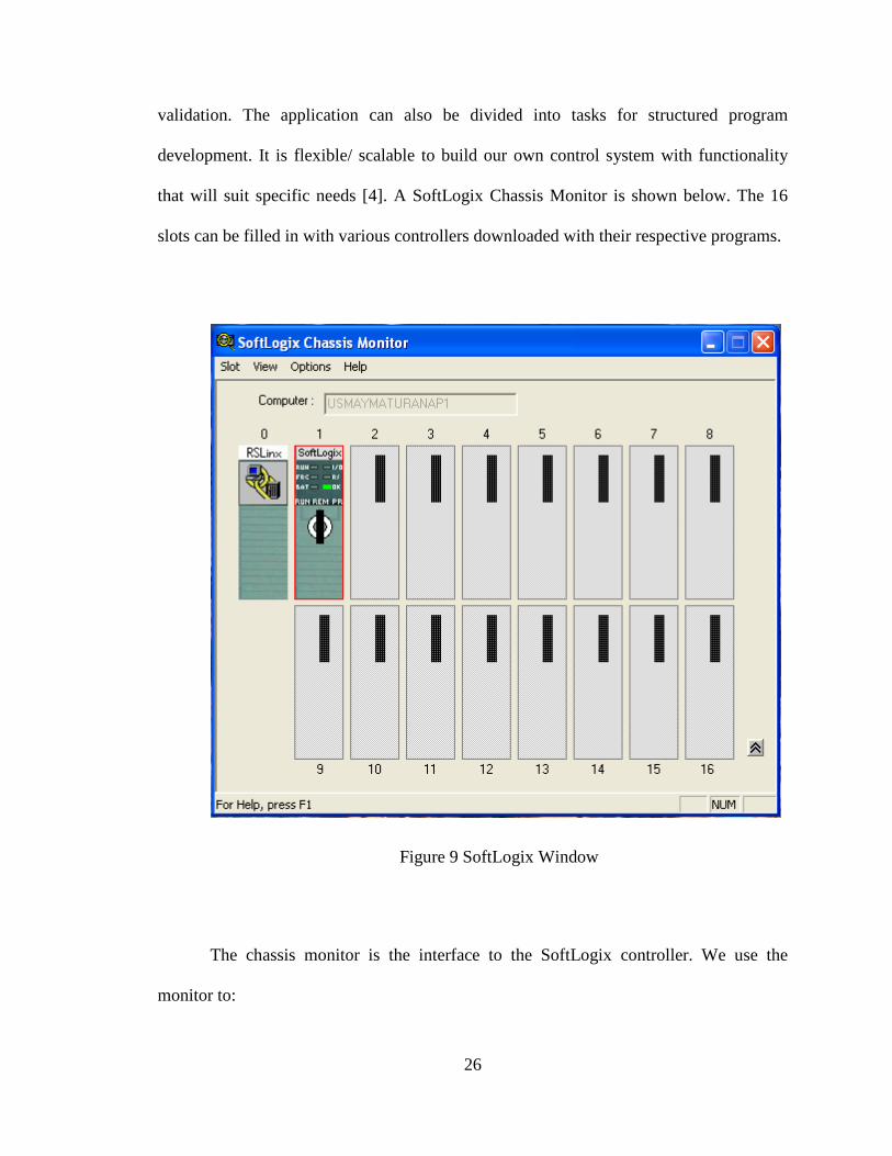
validation. The application can also be divided into tasks for structured program
development. It is flexible/ scalable to build our own control system with functionality
that will suit specific needs [4]. A SoftLogix Chassis Monitor is shown below. The 16
slots can be filled in with various controllers downloaded with their respective programs.
Figure 9 SoftLogix Window
The chassis monitor is the interface to the SoftLogix controller. We use the
monitor to:

27
• Add and configure controllers
• Add and configure communication cards
• Add and configure motion cards
• Change processor mode
• Monitor controller and associated module status
• Monitor motion performance
Based on the requirements, we can define the chassis monitor with number of
slots according to the user preference as shown in the figure below.
Figure 10 SoftLogix Chassis Monitor
A SoftLogix controller is the software that is installed inside the computer. A
computer to have SoftLogix should meet the following requirements.

28
• IBM-compatible Pentium 41.6 GHz
• 256 Kbytes of RAM
• 50 Mbytes hard disk space
4.2 RSLogix 5000
RSLogix 5000 Enterprise Series software is an IEC 61131-3 compliant software
package that offers relay ladder, structured text, function block diagram, and sequential
function chart editors for you to develop application programs [3].
• Instructions can be created by encapsulating a section of logic in any
programming language into an add-on instruction.
• RSLogix 5000 Enterprise Series software also includes axis configuration
and programming support for motion control.
• With RSLogix 5000 Enterprise Series software, only one software
package for sequential, process, drive, motion control, and safety
programming is required.
• The RSLogix 5000 Enterprise Series environment offers an easy-to-use,
IEC61131-3 compliant interface, symbolic programming with structures
and arrays, and a comprehensive instruction set that serves many types of
applications.

29
• It supports relay ladder, structured text, function block diagram, and
sequential function chart editors for you to develop application programs.
PC Hardware Requirements: The client computer must have at least:
• a 600MHz or greater Intel Pentium® II, or Pentium-compatible
microprocessor (1GHz or greater recommended)
• 256 MB of RAM (512 MB or more recommended)
• a CD-ROM drive
• 250 MB of free hard disk space (or more depending on application
requirements)
• a 3.5-inch, 1.4MB disk drive (if using RSLogix 5000 professional for
activation)
For various industrial applications, RSLogix5000 can be used to write logic to provide
automated control.
30
CHAPTER V
STRUCTURES, PROGRAM FLOW AND LOGIC OF ROUTING ALGOR ITHM
The chapter is composed of several sections containing details about the
structures developed, brief explanation of logic behind the algorithm, functions required,
architectural view of how the data and structures are stored in controller memory, and
flowchart that explains the working of the algorithm along with the high level diagram of
functions used in the algorithm.
5.1 Translation of Objects to Structures
Structures developed from Object Oriented Concept presented in chapter 2 are
described as follows.
(a) Valve: Valve is the structure which consists of main data members. The data members
include the coordinates of the valve with respect to valve matrix and two integers
representing indices to valve usage records. In the controller memory, there is an array of

31
valves whose length depends on the number of valves present in a matrix and the number
of matrices. The data structure valve as seen by the user or operator in RS Logix5000
window is shown in Figure 11. The data member, Coordinates is a user defined data type
which consists of row number and column number as its variables.
Figure 11 Data Structure – Valve
(a) Path: As shown in Figure 12, a ‘Path’ structure contains all the information about
the route selected for execution. The starting point and the ending point are the two
members in the ‘path’ structure that specify details about external connections between
which the material is routed. These points are the source and destination of a flow in the
selected path. The points are user defined data types with variables, name and self
coordinates. ‘Name’ identifies external connection and ‘self coordinates’ explain the
location of the “ExternalConnection” with respect to the valve matrix. Another variable is
the ‘coordinates’ of the valve in the matrix to which the “Externalconnection” is
connected. Other Significant member of path structure is an array of integers that
contains indices to a list of records. These records contain detailed information of the
valves participating in material flow. Other required data members are name of the

32
material to be routed through the path and two Boolean variables which specify whether
the structure is in use for the purpose of memory management and whether the path
computation is completed respectively.
(b)
Figure 12 Data Structure – Path
Figure 13 Data Structure Valve Matrix
(c) Valve Matrix: Figure 13 shows the structure ‘Valve Matrix’. ‘Valve Matrix’ is the
data structure whose members are matrix, number of rows, number of columns, number

33
of “ExternalConnections” (source and destinations for the flow across the valve matrix),
and two integers that specify the start position of its valves in the valve array and
“ExternalConnections” respectively.
(d) Valve Proposal Record: The structure identified as ‘Valve Proposal Record’ is used
while computing the path for a specific request. As seen in Figure 14 it contains ‘inuse’
bit for memory management and ‘onpath’ bit for showing whether the material flows
through the valve or the valve is just constrained in order to support the flow through the
requester the route. A proposal record carries the coordinates of the valve which is
supposed to be affected for a particular path. The direction from which the material enters
the valve if it is on path and the direction in which the material continues to flow next are
stored in form of integers (1 – north, 2-south, 3-east, and 4-west). Also there is a data
member ‘proposedstatus’ which is set 1 if the valve is supposed to be open and 0 if
closed. These structures are present in an array of required length which depends on
matrix size and number of matrices. These are accessed from an array of integers called
‘Affected valves’ that serve as indices.
Figure 14 Data Structure – Valve Proposal Record
34
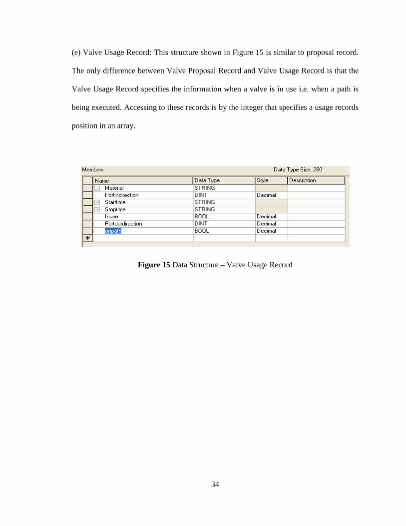
(e) Valve Usage Record: This structure shown in Figure 15 is similar to proposal record.
The only difference between Valve Proposal Record and Valve Usage Record is that the
Valve Usage Record specifies the information when a valve is in use i.e. when a path is
being executed. Accessing to these records is by the integer that specifies a usage records
position in an array.
Figure 15 Data Structure – Valve Usage Record

35
5.2 Data Structures and Data members
Figure 16 and Figure 17 give an outlook of all the structures and members stored
in controller memory as allocated.
Figure 16 Data Structures in Controller Memory (i)
36
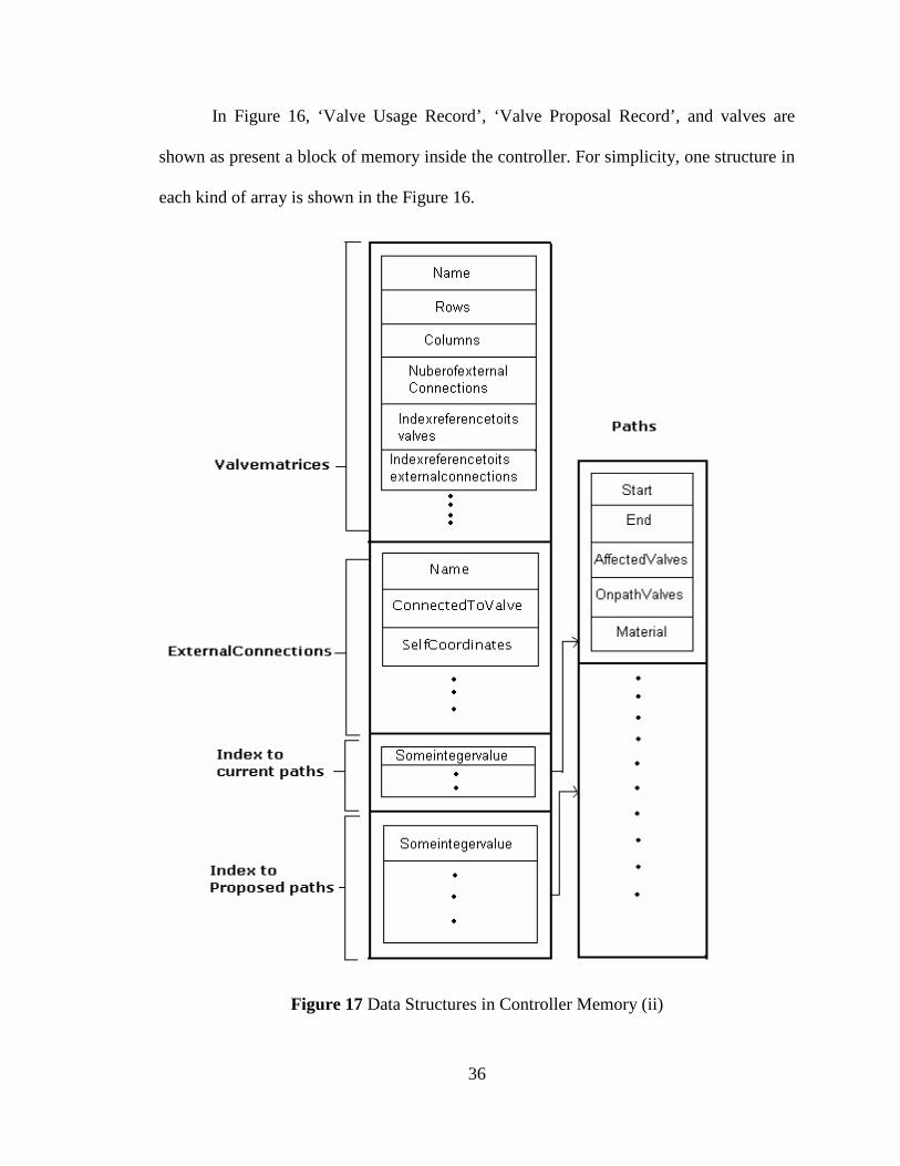
In Figure 16, ‘Valve Usage Record’, ‘Valve Proposal Record’, and valves are
shown as present a block of memory inside the controller. For simplicity, one structure in
each kind of array is shown in the Figure 16.
Figure 17 Data Structures in Controller Memory (ii)

37
The number of such structures in every kind of array depends on the application. The
length of the array is defined based on number of valves and number of matrices in the
application. Similarly, Figure 17 consists of an overview of how valve matrices,
‘External Connections’ and paths are stored as arrays inside the controller memory.
Memory is also allocated for storing the path numbers, which are in execution and
proposed for later execution.
5.3 Introduction to Algorithm
All the above structures were developed in order to write the routing algorithm for
dynamically computing all possible routes when requested. The algorithm is developed
using two programming languages. One language is the ladder logic, and the other
language is structured text. The main routine is developed using ladder logic and all the
other subroutines are developed using structured text. Main routine is the function that
takes a user request and begins the rest process which includes calls to other required
functions.
Figure 18 shows the hierarchy in which few main subroutines are called by the
main routine. The first subroutine called by main routine is ‘Initialize’. This subroutine
initializes all the tags before passing on to execution before any thing else.
Once initialized, the ‘Request’ subroutine initiates the path computation by
staring with first valve connected to the source or starting point of the path which we
have defined as external connection. ‘AddIteration’ queues up the data in a circular

38
buffer which is used for computing the path. A better explanation of data and functions in
this program flow can be found in the next section.
Figure 18 Hierarchical View of Functions in Algorithm
‘Find path’ is the main subroutine that has code required for computing a path for
given request. It executes accordingly by calling the three subroutines ‘Is Healthy’,
‘Finish Path’, and ‘Get Adjacent Valves’. The first subroutine returns Boolean value
stating whether a valve is in a position to participate in routing. ‘Finish Path’ is called
when a path computation comes to an end. The third subroutine is called when the path is
still being computed and next possible valves are to be found out in order to direct the
material flow. Apart from these subroutines, there are several other supporting
subroutines which can be categorized according to their purpose in our routing algorithm.

39
Supporting subroutines include functions for copying data between any two specified
memory locations, functions to check the Boolean status of certain data tags(variables)
and accordingly assign respective values to the data tags or obtain a tag value, finally
leading to efficient memory management. Memory management functions free up the
memory which is not in use by the algorithm at that particular instance and access free
space from the array of structures(as shown in Figure 16 and Figure 17) when requested.
Figure 19 shows all the supporting functions in their respective categorization blocks.
Figure 19 Different Types of Functions in Algorithm

40
Figure 20 Program Flow of Algorithm
A flow chart explaining the basic programming flow is shown in the Figure 20.
To understand the program flow much clearly, a brief explanation is given in this section
41
about different data tag that play important role in calling associated functions to
continue the execution of algorithm.
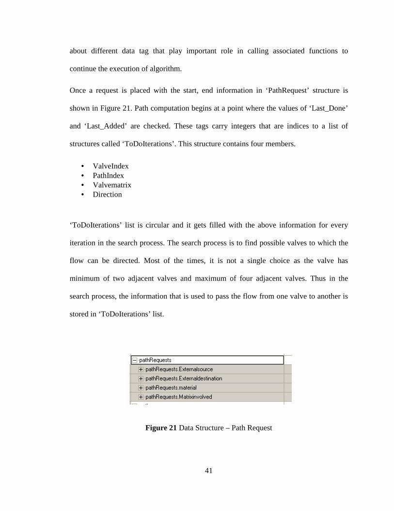
Once a request is placed with the start, end information in ‘PathRequest’ structure is
shown in Figure 21. Path computation begins at a point where the values of ‘Last_Done’
and ‘Last_Added’ are checked. These tags carry integers that are indices to a list of
structures called ‘ToDoIterations’. This structure contains four members.
• ValveIndex • PathIndex • Valvematrix • Direction
‘ToDoIterations’ list is circular and it gets filled with the above information for every
iteration in the search process. The search process is to find possible valves to which the
flow can be directed. Most of the times, it is not a single choice as the valve has
minimum of two adjacent valves and maximum of four adjacent valves. Thus in the
search process, the information that is used to pass the flow from one valve to another is
stored in ‘ToDoIterations’ list.
Figure 21 Data Structure – Path Request

42
Thus by checking the Last_Done and Last_Added values, the algorithm decides whether
the search is still to be done. If both the values are equal, it is obvious that the search tree
has been completely traversed and paths are generated. When Last_Done and
Last_Added are not equal, the ‘Mainroutine’ calls ‘FindPath’ with the updated
information. As shown in the flowchart the updated information is present in
‘ToDoIteration’ list. This can be seen in Figure 22.
Figure 22 Data Structure – toDoIterations
These five basic functions form the base for routing algorithm. ‘FindPath’ is the main
subroutine that directs the program flow. The program flow depends on the possible
surrounding valves through which the material flow can be directed. The selection of next
valve in the route depends on the valve working condition, status. The status may include
if the valve is already in use and associated with some other path or whether it is a last
valve in that particular path. This algorithm is developed for the example valve matrix of

43
nine valves. The algorithm can also be extended to matrices with more than nine valves
or multiple matrices with necessary changes.
Table 1 clearly explains the basic functions used in developing the algorithm. For
each function, other functions it calls and functions by which it is called are included in
the table. ‘Data passed’ and ‘Data Returned’ specify different parameters passed into the
specific functions. The column Explanation includes the instance in which a particular
function is called.
Table 1 Basic Functions in the Program
Flow

44
CHAPTER VI
SIMULATION RESULTS OF ROUTE CONTROL ALGORITHM
The objective of this thesis is to develop route control algorithm for beverage
industry application. The control algorithm should generate dynamically all the possible
routes through which a beverage can be routed between two different points in the
beverage industry. In this chapter, we present the simulated results obtained after running
the route control algorithm in SoftLogix controller successfully.
Figure 23 shows the valve matrix of nine valves as described in chapter 2. All the
valves are marked with their respective coordinates and index values. The numbers ‘0’,
‘1’, ‘2’ outside the matrix represent the positioning of “ExternalConnections”. Arrow
marks show that the request is put to compute the routes from point ‘2’ to point ‘1’. The
request is entered in the ‘PathRequest’ structure by the user/operator. The algorithm that
is executed and all the possible routes between the requested source and destination are
computed.

45
Figure 23 Valve Matrix
The computed paths are identified by path numbers and these path numbers are
stored in the structure ‘Pathslisted’. These numbers are the indices to the ‘Paths’
structures array as shown in the figure 17. Snap shots of ‘Path Request’ and ‘Pathslisted’
structures are shown in Figure 24 and Figure 25 respectively.

46
Figure 24 Data Structure – PathRequest
In the Figure 25, we can see five indices in the paths listed structure ‘5’, ‘2’, ‘3’,
‘4’, ‘1’. ’-1’ in the ‘pathslisted’ structure indicates that rest of the array members have not
been used. This indicates our request has resulted five possible routes between the points
‘2’ and ‘1’.
The routes computed matched perfectly with those found manually. Also the
‘path’ structure in which the information about the computed route/path is stored has
been found exactly filled in with the expected data. In Figure 26
‘pathRequests.ExternalSource’ as ‘2’ indicates that we are requesting the routes from
point ‘2’ in the ‘valve matrix’ layout. Similarly ‘pathRequests.Externaldestination’ as ‘1’
shows that we are requesting routes to the point ‘3’ connected externally to the valve
matrix. ‘pathRequests.material’ and ‘pathRequests.Matrixinvolved’ are data variables to
enter the material to be routed in the process and valve matrix through which it is routed
when multiple matrices are present. After filling this information ‘reqRoute’ bit has to be
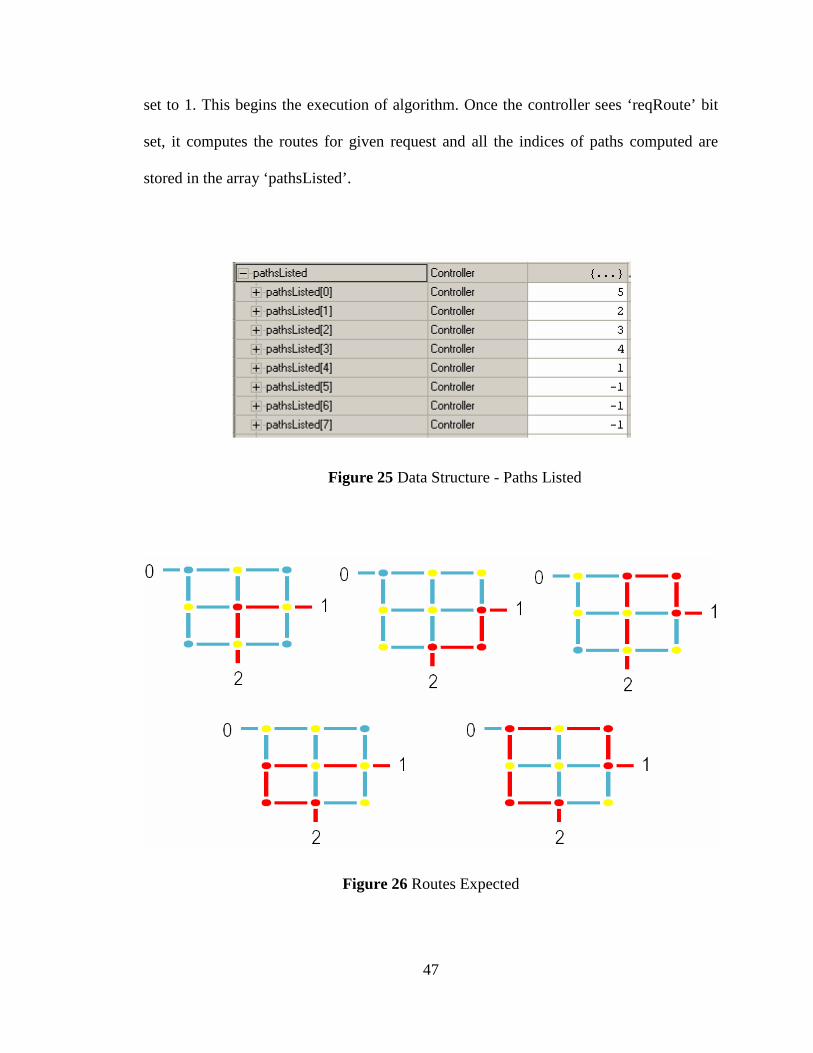
47
set to 1. This begins the execution of algorithm. Once the controller sees ‘reqRoute’ bit
set, it computes the routes for given request and all the indices of paths computed are
stored in the array ‘pathsListed’.
Figure 25 Data Structure - Paths Listed
Figure 26 Routes Expected

48
If we try to compute the possible routes between point ‘2’ and point ‘1’ as given
in the request, following five routes (as shown in the Figure 26) can be identified for our
example valve matrix with out the help of route control algorithm. In Figure 26 the five
possible routes are marked. In the next section the routes computed by the algorithm
whose indices are shown in the structure ‘PathsListed’ are explained in detail.
6.1 Route - Valves and Constraints
The ‘path’ structure as present in RS Logix5000 Screen is shown in Figure 27. To
avoid ambiguity and loads of data, a single ‘path’ structure has been expanded. As
explained in the previous chapter, all the information about the material flow through a
route is collected by the data structure ‘ValveProposalRecord’.
It contains
• Starting point name – start
• Ending point name – end
• Material to be routed in the selected path
• Array of integers which serve as indices to ‘ValveProposalRecords’
• ‘Inuse’ bit indicating that this structure is in use and avoiding the
overwriting when another request is entered.
• ‘pathCompleted’ bit which is used in the route computation process.

49
Figure 27 Data Structure - Path
The numbers in Figure 3 showing ‘Affectedvalves’ represent indices to the ‘Valve
Proposal Records’. In Figure 28, we can see the details of the computed route. The path 5
consists of three valves. The respective three valves are ‘7’, ‘4’, and‘5’.

50
Figure 28 One possible route for the given request
In Figure 28 dark colored circle numbered ‘4’ represents the valve to be in open
state for this particular route. Other valves in the route are ‘7’ and ‘5’ stay in closed state.
Valves ‘3’ and ‘1’ do not participate in the routing but are constrained to be closed
because of the open state of valve ‘4’. Remaining valves ‘0’, ‘2’, ‘6’ and ‘8’ are
unaffected valves and are not constrained with respect to this route.
Thus the user or operator expects same information as output when the algorithm
is run in SoftLogix controller. Figure 29 shows the snap shot of all the ‘valve proposal
records’ whose indices were listed in ‘path’ structure. The five ‘Valve Proposal Records’
are ‘20’, ‘21’, ‘22’, ’23 and ’24’. As we know, these records contain the information
about the valves used in route execution.
If observed carefully, the order in which indices are listed is same as the order in
which the valves are present in the selected path.

51
The ‘onpath’ bit in Figure 29 indicates whether the respective valve participates in
the path (if ‘1’) or just an affected valve (if ‘0’).
Figure 29 Valve Proposal Records
52
The ‘inuse’ bit is again for memory management. The coordinates of all the
‘onpath’ valves exactly are same as the valves highlighted in figure 5 by a right angled
box.
The valve is to be closed if its ‘proposedstatus’ bit is set to ‘0’ and open if set to
‘1’. In the Figure 28, we can see that ‘proposedstatus’ bits for valves ‘1’, ‘3’, ‘5’ and ‘8’
are set to ‘0’ indicating that they should remain close when this path is selected to route
the beverage through it. The ‘proposedstatus’ bit for the valve ‘4’ is set to ‘1’ indicating
that the valve ‘4’ should be open.
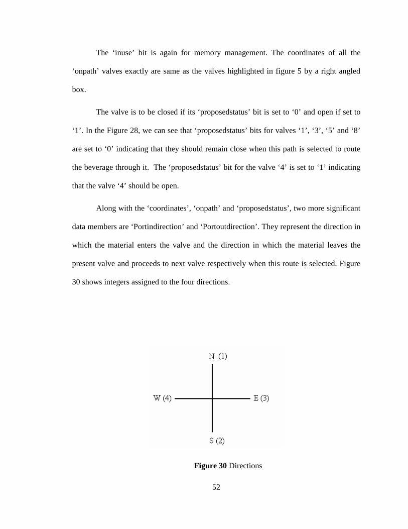
Along with the ‘coordinates’, ‘onpath’ and ‘proposedstatus’, two more significant
data members are ‘Portindirection’ and ‘Portoutdirection’. They represent the direction in
which the material enters the valve and the direction in which the material leaves the
present valve and proceeds to next valve respectively when this route is selected. Figure
30 shows integers assigned to the four directions.
Figure 30 Directions
53
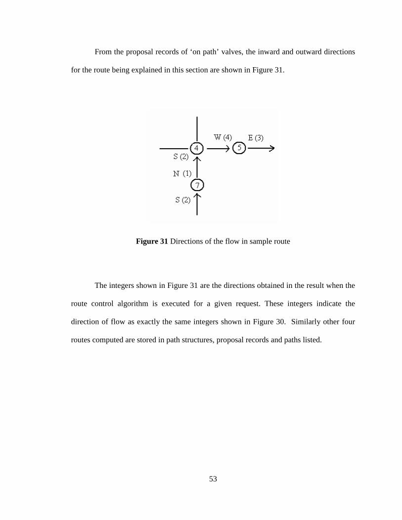
From the proposal records of ‘on path’ valves, the inward and outward directions
for the route being explained in this section are shown in Figure 31.
Figure 31 Directions of the flow in sample route
The integers shown in Figure 31 are the directions obtained in the result when the
route control algorithm is executed for a given request. These integers indicate the
direction of flow as exactly the same integers shown in Figure 30. Similarly other four
routes computed are stored in path structures, proposal records and paths listed.

54
CHAPTER VII
CONCLUSION AND FUTURE WORK
Our goal was to develop a route control algorithm which computes routes
dynamically and which can be implemented in the existing programmable logic
controller without any firmware modifications. We can see from the simulation snapshots
that the algorithm is computing the routes through a valve matrix dynamically. It can be
implemented in the existing controller. The algorithm presents all the data about the
routes and valves as output to the user or operator. By looking at the path structure an
operator or user knows completely about the route.
All the information about the affected valves and participating valves is presented.
Also the direction in which the material is flowing is given from valve to valve. When
this algorithm is downloaded into the processor of the controller, the memory used by the
algorithm is very less that adds another advantage to use this route control algorithm. The
memory is about 2000KB. The memory size changes with number of ‘ValveMatrices’
and number of ‘valves’. Another advantage to this routing control algorithm is that it only
55
adds about another 200K to the program memory requirements. This algorithm
introduces preliminary solution for the beverage route control problem.
The Route control algorithm can be extended to meet several other specifications
commonly presented by the beverage industries.
Functions can be written to assure that the routing algorithm can be applied to
multiple matrices in the same controller. The algorithm can be modified to accommodate
following features.
• Sorting the obtained paths based on different criteria – When all the paths
have been computed for a given request, user may need to sort these paths
before executing them. The sorting may be based on choosing shortest
path, which does not contain certain valves to avoid interference with
another route being executed, etc.
• Restrictions based on material – Some materials can follow other materials
in pipe while some cannot. Sorting functions can be written to support
these criteria.
• Consideration of timestamps – Pipes, valves and containers require
cleaning in order to maintain the quality of beverages being passed
through them. The algorithm can also be altered to keep track of time
when they are cleaned.

56
• Planning for multiple materials simultaneously – Logic can be developed
using the same algorithm in order to route multiple materials at the same
time.
• Volumetric/pipe diameter considerations - In the plant, there may be some
restrictions. Some materials may be more viscous and cannot be passed
through thin pipes. In such case, certain routes may not be feasible for
such materials. Algorithm can be changed to include logic for efficient
selection of routes.
• Valve out-of-service/stuck – The information about the valves that are
under maintenance and repair works can be stored in the data structures.
This will help in efficient routing.
• Routing from multiple inputs/to multiple outputs – Materials can be routed
between a single input and multiple outputs or other wise. This may be
due to various sizes of the beverage storage tanks.
• Routing through multiple matrices - In the beverage industries, beverages
need to be sent across several sections of equipment in their
manufacturing process at most time. This leads to the concept of multiple
matrices.
• Development of appropriate configuration tool – A software tool need to
be developed that allows the user to configure matrices at the time of
setting up the controller. In the Logix controller every thing has to be

57
defined statistically. This configuration helps to define the size of the
matrix, number of matrices, number of “External Connections”, etc.
• Development of operator screen(s) for monitoring and control – A user
interface has to be developed for monitoring and controlling the selection
and execution of routes. This may include operator screens showing up
status of the routes in execution, routes waiting for execution, list of routes
generated for a given request etc.

58
REFERENCES
1. R.W.Lewis. “Programming Industrial Control Systems using IEC 1131-3”.
2. NEMA IA 2.1-2005, PROGRAMMABLE LOGIC CONTROLLERS, NATIONAL ELECTRICAL MANUFACTURERS ASSOCIATION, NEMA STANDARDS PUBLICATION.
3. NEMA IA 2.1-2005, PROGRAMMING LANGUAGES FOR PLCS, NATIONAL ELECTRICAL MANUFACTURERS ASSOCIATION, NEMA STANDARDS PUBLICATION.
4. Product Instruction Manual, RSLogix5000.
5. Product Instruction Manual, SoftLogix.
6. Beverage Path Selection Functional Specification, (Confidential Material).
7. http://en.wikipedia.org/wiki/Programmable_logic_controller.
8. http://www.plcs.net/chapters/howworks4.htm.
9. http://www.plcs.net/chapters/whatis1.htm.
10. http://en.wikipedia.org/wiki/Ladder_logic
11. http://www.prismvs.com/whoweare.html
12 http://www.esri.com/software/arclogistics/about/industries/food.html