platform monitoring guide
TRANSCRIPT

HardwarePlatform Monitoring Guide
Network Appliance, Inc.495 East Java DriveSunnyvale, CA 94089 USATelephone: +1 (408) 822-6000Fax: +1 (408) 822-4501Support telephone: +1 (888) 4-NETAPPDocumentation comments: [email protected] Web: http://www.netapp.com
Part number 215-03512_A0February 2008
Copyright and trademark information
Copyright information
Copyright © 1994–2008 Network Appliance, Inc. All rights reserved. Printed in the U.S.A.
No part of this document covered by copyright may be reproduced in any form or by any means—graphic, electronic, or mechanical, including photocopying, recording, taping, or storage in an electronic retrieval system—without prior written permission of the copyright owner.
Network Appliance reserves the right to change any products described herein at any time, and without notice. Network Appliance assumes no responsibility or liability arising from the use of products described herein, except as expressly agreed to in writing by Network Appliance. The use or purchase of this product does not convey a license under any patent rights, trademark rights, or any other intellectual property rights of Network Appliance.
The product described in this manual may be protected by one or more U.S.A. patents, foreign patents, or pending applications.
RESTRICTED RIGHTS LEGEND: Use, duplication, or disclosure by the government is subject to restrictions as set forth in subparagraph (c)(1)(ii) of the Rights in Technical Data and Computer Software clause at DFARS 252.277-7103 (October 1988) and FAR 52-227-19 (June 1987).
Trademark information
NetApp, the Network Appliance logo, the bolt design, NetApp–the Network Appliance Company, DataFabric, Data ONTAP, FAServer, FilerView, FlexClone, FlexVol, Manage ONTAP, MultiStore, NearStore, NetCache, SecureShare, SnapDrive, SnapLock, SnapManager, SnapMirror, SnapMover, SnapRestore, SnapValidator, SnapVault, Spinnaker Networks, SpinCluster, SpinFS, SpinHA, SpinMove, SpinServer, SyncMirror, Topio, VFM, and WAFL are registered trademarks of Network Appliance, Inc. in the U.S.A. and/or other countries. Cryptainer, Cryptoshred, Datafort, and Decru are registered trademarks, and Lifetime Key Management and OpenKey are trademarks, of Decru, a Network Appliance, Inc. company, in the U.S.A. and/or other countries. gFiler, Network Appliance, SnapCopy, Snapshot, and The evolution of storage are trademarks of Network Appliance, Inc. in the U.S.A. and/or other countries and registered trademarks in some other countries. ApplianceWatch, BareMetal, Camera-to-Viewer, ComplianceClock, ComplianceJournal, ContentDirector, ContentFabric, EdgeFiler, FlexShare, FPolicy, HyperSAN, InfoFabric, LockVault, NOW, NOW NetApp on the Web, ONTAPI, RAID-DP, RoboCache, RoboFiler, SecureAdmin, Serving Data by Design, SharedStorage, Simplicore, Simulate ONTAP, Smart SAN, SnapCache, SnapDirector, SnapFilter, SnapMigrator, SnapSuite, SohoFiler, SpinMirror, SpinRestore, SpinShot, SpinStor, StoreVault, vFiler, Virtual File Manager, VPolicy, and Web Filer are trademarks of Network Appliance, Inc. in the United States and other countries. NetApp Availability Assurance and NetApp ProTech Expert are service marks of Network Appliance, Inc. in the U.S.A.
IBM, the IBM logo, AIX, and System Storage are trademarks and/or registered trademarks of International Business Machines Corporation.
Apple is a registered trademark and QuickTime is a trademark of Apple Computer, Inc. in the United States and/or other countries. Microsoft is a registered trademark and Windows Media is a trademark of Microsoft Corporation in the United States and/or other countries. RealAudio, RealNetworks, RealPlayer, RealSystem, RealText, and RealVideo are registered trademarks and RealMedia, RealProxy, and SureStream are trademarks of RealNetworks, Inc. in the United States and/or other countries.
All other brands or products are trademarks or registered trademarks of their respective holders and should be treated as such.
ii Copyright and trademark information

Network Appliance is a licensee of the CompactFlash and CF Logo trademarks.
Network Appliance NetCache is certified RealSystem compatible.
Copyright and trademark information iii

iv Copyright and trademark information

Table of contents
Preface . . . . . . . . . . . . . . . . . . . . . . . . . . . . . . . . . . . . . vii
Chapter 1 Finding troubleshooting information . . . . . . . . . . . . . . . . . . . . . 1
What this guide covers . . . . . . . . . . . . . . . . . . . . . . . . . . . . . . 2
Other sources for hardware troubleshooting information . . . . . . . . . . . . 3
Chapter 2 Interpreting LEDs . . . . . . . . . . . . . . . . . . . . . . . . . . . . . . . . 5
Platform-specific LED information . . . . . . . . . . . . . . . . . . . . . . . 6FAS2000 series systems . . . . . . . . . . . . . . . . . . . . . . . . . . 7FAS3000/V3000 series systems, and C2300 and C3300 NetCache applianc-es . . . . . . . . . . . . . . . . . . . . . . . . . . . . . . . . . . . . . 12FAS6000 series and V6000 series systems . . . . . . . . . . . . . . . 18C1300 NetCache appliances . . . . . . . . . . . . . . . . . . . . . . . 23
Host bus adapter LEDs . . . . . . . . . . . . . . . . . . . . . . . . . . . . . 26
GbE NIC LEDs . . . . . . . . . . . . . . . . . . . . . . . . . . . . . . . . . 33
TCP offload engine NIC LEDs . . . . . . . . . . . . . . . . . . . . . . . . . 36
NVRAM5 and NVRAM6 adapter LEDs . . . . . . . . . . . . . . . . . . . . 40
NVRAM5 and NVRAM6 media converter LEDs . . . . . . . . . . . . . . . 42
Chapter 3 Startup error messages . . . . . . . . . . . . . . . . . . . . . . . . . . . . 43
Types of startup error messages . . . . . . . . . . . . . . . . . . . . . . . . 44
POST error messages . . . . . . . . . . . . . . . . . . . . . . . . . . . . . . 47FAS3020/V3020 and FAS3050/V3050 systems, and C2300 and C3300 NetCache appliances . . . . . . . . . . . . . . . . . . . . . . . . . . . 48FAS3040/V3040 and FAS3070/V3070 systems, and FAS6000/V6000 se-ries systems. . . . . . . . . . . . . . . . . . . . . . . . . . . . . . . . 51C1300 NetCache appliances . . . . . . . . . . . . . . . . . . . . . . . 59
Boot error messages . . . . . . . . . . . . . . . . . . . . . . . . . . . . . . 68
Chapter 4 Interpreting EMS and operational error messages . . . . . . . . . . . . . 75
FAS2000 series system AutoSupport error messages . . . . . . . . . . . . . 76
EMS error messages . . . . . . . . . . . . . . . . . . . . . . . . . . . . . . 83
Table of Contents v

Environmental EMS error messages . . . . . . . . . . . . . . . . . . . . . . 98
Operational error messages . . . . . . . . . . . . . . . . . . . . . . . . . . .140
Chapter 5 Understanding Remote LAN Module messages . . . . . . . . . . . . . . .143
Chapter 6 Understanding BMC messages . . . . . . . . . . . . . . . . . . . . . . . .159
Index . . . . . . . . . . . . . . . . . . . . . . . . . . . . . . . . . . . . . .175
vi Table of Contents
Preface
About this guide This guide describes hardware platform error messages generated by storage systems and basic methods of troubleshooting hardware problems.
Audience This guide is for both end-users and Professional Service personnel.
Command conventions
You can enter storage appliance commands on the system console or from any client that can obtain access to the appliance using a Telnet session. In examples that illustrate commands executed on a UNIX® workstation, the command syntax and output might differ, depending on your version of UNIX.
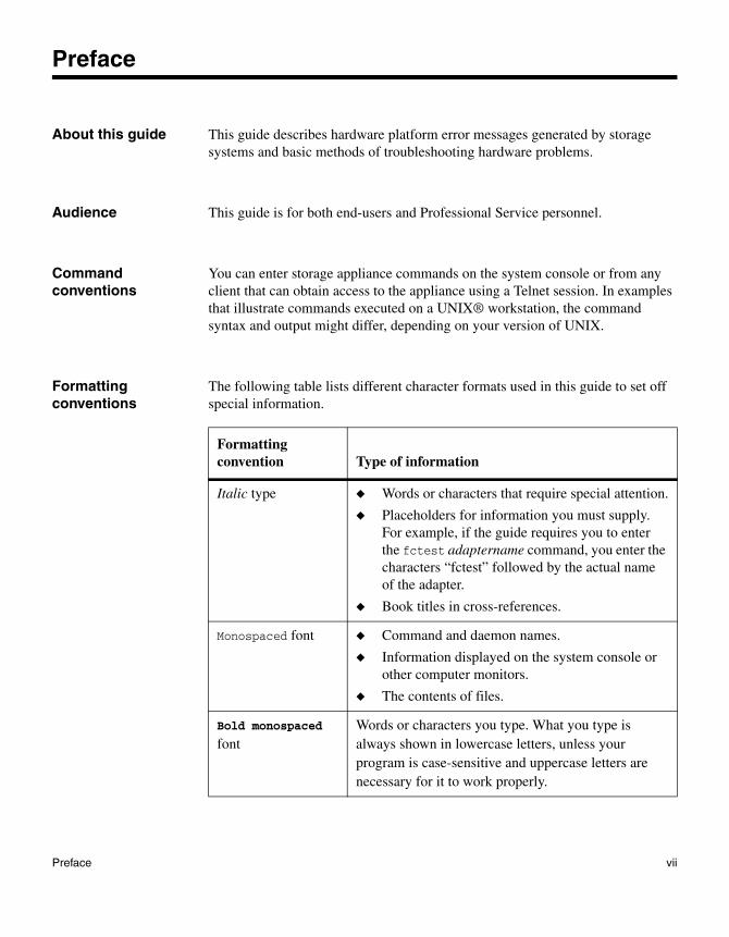
Formatting conventions
The following table lists different character formats used in this guide to set off special information.
Formatting convention Type of information
Italic type ◆ Words or characters that require special attention.
◆ Placeholders for information you must supply. For example, if the guide requires you to enter the fctest adaptername command, you enter the characters “fctest” followed by the actual name of the adapter.
◆ Book titles in cross-references.
Monospaced font ◆ Command and daemon names.
◆ Information displayed on the system console or other computer monitors.
◆ The contents of files.
Bold monospaced font
Words or characters you type. What you type is always shown in lowercase letters, unless your program is case-sensitive and uppercase letters are necessary for it to work properly.
Preface vii
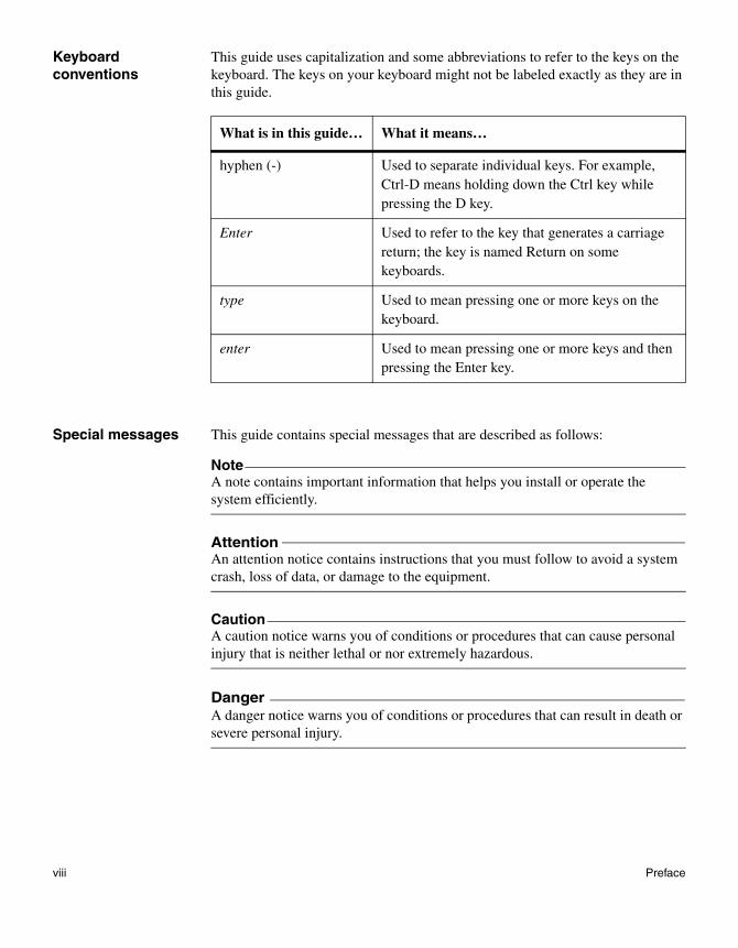
Keyboard conventions
This guide uses capitalization and some abbreviations to refer to the keys on the keyboard. The keys on your keyboard might not be labeled exactly as they are in this guide.
Special messages This guide contains special messages that are described as follows:
NoteA note contains important information that helps you install or operate the system efficiently.
AttentionAn attention notice contains instructions that you must follow to avoid a system crash, loss of data, or damage to the equipment.
CautionA caution notice warns you of conditions or procedures that can cause personal injury that is neither lethal or nor extremely hazardous.
DangerA danger notice warns you of conditions or procedures that can result in death or severe personal injury.
What is in this guide… What it means…
hyphen (-) Used to separate individual keys. For example, Ctrl-D means holding down the Ctrl key while pressing the D key.
Enter Used to refer to the key that generates a carriage return; the key is named Return on some keyboards.
type Used to mean pressing one or more keys on the keyboard.
enter Used to mean pressing one or more keys and then pressing the Enter key.
viii Preface
Chapter 1: Finding troubleshooting information
1
Finding troubleshooting informationAbout this chapter This chapter discusses the following topics:
◆ “What this guide covers” on page 2
◆ “Other sources for hardware troubleshooting information” on page 3
1
What this guide covers
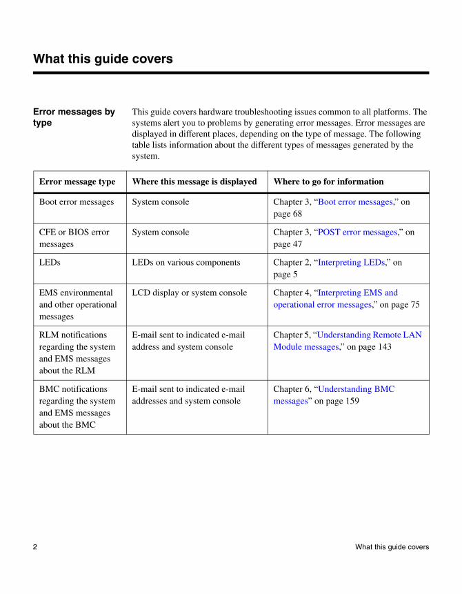
Error messages by type
This guide covers hardware troubleshooting issues common to all platforms. The systems alert you to problems by generating error messages. Error messages are displayed in different places, depending on the type of message. The following table lists information about the different types of messages generated by the system.
Error message type Where this message is displayed Where to go for information
Boot error messages System console Chapter 3, “Boot error messages,” on page 68
CFE or BIOS error messages
System console Chapter 3, “POST error messages,” on page 47
LEDs LEDs on various components Chapter 2, “Interpreting LEDs,” on page 5
EMS environmental and other operational messages
LCD display or system console Chapter 4, “Interpreting EMS and operational error messages,” on page 75
RLM notifications regarding the system and EMS messages about the RLM
E-mail sent to indicated e-mail address and system console
Chapter 5, “Understanding Remote LAN Module messages,” on page 143
BMC notifications regarding the system and EMS messages about the BMC
E-mail sent to indicated e-mail addresses and system console
Chapter 6, “Understanding BMC messages” on page 159
2 What this guide covers

Other sources for hardware troubleshooting information
Other sources If you do not find the troubleshooting information you need in this guide, use the following table to determine where you can find the information you need.
Platform type Topic Document
Filer and FAS systems
FAS6000 series
FAS3000 series
FAS2000 series
This guide
FAS900 series FAS900 Hardware Service Guide
FAS250
FAS270
FAS250/270 Hardware and Service Guide
F800 F800 Hardware Installation Guide
F87 F87 Hardware and Service Guide
F85 F85 Hardware and Service Guide
V-Series Systems
and gFiler™ gateways
V3000 series
V6000 series
This guide
V900
V270c
GF825
gFiler Hardware Maintenance Guide
Chapter 1: Finding troubleshooting information 3

Near Store® systems
R200 R200 Hardware and Service Guide
R150 R150 Hardware and Service Guide
R100 R100 Hardware and Service Guide
NetCache® appliances
C1300/C2300/C3000 This guide
C6200 C6200 Hardware and Service Guide
C6100/C3100 C6100/C3100 Hardware and Service Guide
C1200/C2100 C1200/C2100 Hardware and Service Guide
Disk shelves DS24 DS24 Hardware Guide
DS14mk2 FC DS14mk2 FC Hardware Guide
DS14mk2 AT DS14mk2 AT Hardware Guide
FC9 FC9 Hardware Guide
Third-party hardware
Switches, routers, storage subsystems, and tape backup devices
Applicable third-party hardware documentation
Platform type Topic Document
4 Other sources for hardware troubleshooting information
Chapter 2: Interpreting LEDs
2
Interpreting LEDsAbout this chapter This chapter describes the interpretation of LEDs for basic monitoring of your system.
For detailed information
For detailed information about the LEDs, see the following sections:
◆ “Platform-specific LED information” on page 6
◆ “Host bus adapter LEDs” on page 26
◆ “GbE NIC LEDs” on page 33
◆ “TCP offload engine NIC LEDs” on page 36
◆ “NVRAM5 and NVRAM6 adapter LEDs” on page 40
◆ “NVRAM5 and NVRAM6 media converter LEDs” on page 42
5

Platform-specific LED information
Types of platform-specific LEDs
Two sets of LEDs provide you with basic information about how your system is running. These sets give high-level device status at a glance, along with network activity:
◆ LEDs visible on the front of your storage system with the bezel in place
◆ LEDs visible on the back of your storage system
6 Platform-specific LED information

Platform-specific LED information
FAS2000 series systems
About this section This section provides LED information specific toFAS2020 and FAS2050 storage systems.
LEDs visible from the front
Location of the LEDs: The following illustration shows the LEDs on the front panel of a FAS2000 series storage system.
What the LEDs mean: The following table explains what the front panel subassembly LEDs mean.
Fault
Power
Controller A
Controller B!
A
B
Power
Fault
ControllerModule A
ControllerModule B
Icon LED labelStatus indicator Description
Power Green The system is receiving power.
Off The system is not receiving power.
Chapter 2: Interpreting LEDs 7
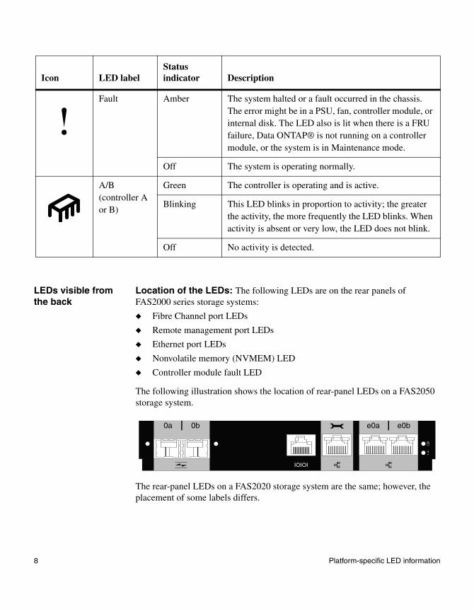
LEDs visible from the back
Location of the LEDs: The following LEDs are on the rear panels of FAS2000 series storage systems:
◆ Fibre Channel port LEDs
◆ Remote management port LEDs
◆ Ethernet port LEDs
◆ Nonvolatile memory (NVMEM) LED
◆ Controller module fault LED
The following illustration shows the location of rear-panel LEDs on a FAS2050 storage system.
The rear-panel LEDs on a FAS2020 storage system are the same; however, the placement of some labels differs.
Fault Amber The system halted or a fault occurred in the chassis. The error might be in a PSU, fan, controller module, or internal disk. The LED also is lit when there is a FRU failure, Data ONTAP® is not running on a controller module, or the system is in Maintenance mode.
Off The system is operating normally.
A/B (controller A or B)
Green The controller is operating and is active.
Blinking This LED blinks in proportion to activity; the greater the activity, the more frequently the LED blinks. When activity is absent or very low, the LED does not blink.
Off No activity is detected.
Icon LED labelStatus indicator Description
e0be0a0a 0b
8 Platform-specific LED information

What the LEDs mean: The following table explains what your system’s rear-panel LEDs mean.
Icon Port type LED typeStatus indicator Description
Fibre Channel
LNK Green Link is established and communication is happening.
Off No link is established.
Remote management
LNK
(Left)
Green A valid network connection is established.
Off There is no network connection present.
ACT
(Right)
Amber There is data activity.
Off There is no network activity present.
Ethernet LNK
(Left)
Green A valid network connection is established.
Off There is no network connection present.
ACT
(Right)
Amber There is data activity.
Off There is no network activity present.
NVMEM Battery Blinking green
NVMEM is in battery-backed standby mode.
Off(power on)
The system is running normally, and NVMEM is armed if Data ONTAP is running.
Off(power off)
The system is shut down, NVMEM is not armed, and the battery is not enabled.
Controller module fault
ACT Amber Controller is starting up, Data ONTAP is initializing, the controller is in Maintenance mode, or a controller module fault is detected.
Off Controller module is functioning properly.
Chapter 2: Interpreting LEDs 9
Admonitions about NVMEM status
Several actions should not be performed on either the FAS2020 or FAS2050 storage system if the NVMEM status LED is blinking or if NVMEM is armed (being protected).
AttentionDo not replace DIMMs or any other system hardware when the NVMEM status LED is blinking. Doing so might cause you to lose data. Always flush NVMEM contents to disk by entering a halt command at the system prompt before replacing the hardware.
If you replace DIMMs, be sure to follow the proper procedure. See Replacing DIMMs in a FAS2000 Series System on the NetApp on the Web™ (NOW) site.
AttentionTo protect critical data in NVMEM, you cannot update BIOS or BMC firmware when NVMEM is in use. Before updating firmware, ensure that NVMEM no longer contains critical data by performing a halt command to cleanly shut down Data ONTAP. When the system reboots to the LOADER> prompt, you can update your firmware.
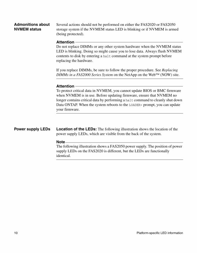
Power supply LEDs Location of the LEDs: The following illustration shows the location of the power supply LEDs, which are visible from the back of the system.
NoteThe following illustration shows a FAS2050 power supply. The position of power supply LEDs on the FAS2020 is different, but the LEDs are functionally identical.
10 Platform-specific LED information
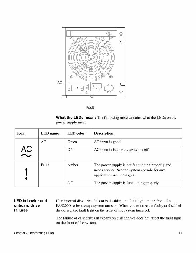
What the LEDs mean: The following table explains what the LEDs on the power supply mean.
LED behavior and onboard drive failures
If an internal disk drive fails or is disabled, the fault light on the front of a FAS2000 series storage system turns on. When you remove the faulty or disabled disk drive, the fault light on the front of the system turns off.
The failure of disk drives in expansion disk shelves does not affect the fault light on the front of the system.
2
AC
Fault
Icon LED name LED color Description
AC Green AC input is good
Off AC input is bad or the switch is off.
Fault Amber The power supply is not functioning properly and needs service. See the system console for any applicable error messages.
Off The power supply is functioning properly
AC
Chapter 2: Interpreting LEDs 11

Platform-specific LED information
FAS3000/V3000 series systems, and C2300 and C3300 NetCache appliances
About this section This section provides LED information specific to the following platforms:
◆ FAS3000 series storage systems
◆ V3000 series systems
◆ C2300 NetCache appliances
◆ C3300 NetCache appliances
Using quick reference sheets
Your system might be shipped with a model-specific quick reference sheet located at the bottom of the chassis.
Check the LEDs: Check all system LEDs to determine whether any components are not functioning properly. The following illustration shows the portion of a quick reference sheet that shows LED locations and explanations.
Match power supply LEDs
with the following possible
conditions and perform
actions from KEY section
Match fan LED with the
following possible conditions
and perform action from
KEY section
Match hard drive LEDs with the following
possible conditions and perform action
from KEY section
hard drive LED’hard drive LED power supply LED’power supply LED s fan LED
GREEN LEDAC
OK
STATUS
AMBER LED
s s
12 Platform-specific LED information

FRU Map: Use the FRU map on the reference sheet to identify field-replaceable units in your system.
LEDs visible from the front
Location of the LEDs: The following illustration shows the LEDs on the front panel subassembly.
Activity LED
Status LED
Power LED
Chapter 2: Interpreting LEDs 13

What the LEDs mean: The following table explains what the front panel subassembly LEDs mean.
LED label
Status indicator Description
Activity Green The system is operating and is active.
Blinking The system is actively processing data.
Off No activity is detected.
Status Green The system is operating normally.
Amber The system halted or a fault occurred. The fault is displayed in the LCD.
NoteThis LED remains lit during boot, while the operating system loads.
Power Green The system is receiving power.
Off The system is not receiving power.
14 Platform-specific LED information

LEDs visible from the back
Location of the LEDs: The following illustration shows the location of the following onboard port LEDs on the system backplane:
◆ Fibre Channel port LEDs
◆ GbE port LEDs
◆ RLM LEDs
What the LEDs mean: The following table explains what the LEDs for your onboard ports mean.
GbE port LEDs
Fibre Channelport LEDs
RLM LEDs
Port type
LED type
Status indicator Description
Fibre Channel
LNK Off No link with the Fibre Channel is established.
Green A link is established.
GbEandRLM
LNK On A valid network connection is established.
Off There is no network connection.
ACT On There is data activity.
Off There is no network activity present.
Chapter 2: Interpreting LEDs 15

Power supply LEDs Location of the LEDs: The following illustration shows the location of the power supply LEDs on your system backplane.
What the LEDs mean: The following table explains what the LEDs on the power supplies mean.
PSU1
PSU LEDs
PSU 2
AC OK
AC OK
LED label Status indicator Description
AC Amber No fault is indicated.
OK (or Status) Green
AC Off There is no external power; check the connections and the power source.
OK (or Status) Off
AC Amber ◆ (FAS3020, FAS3050, V3020 and V3050 systems) Common Firmware Environment (CFE) prompt.
◆ (FAS3040, FAS3070, V3040, and V3070 systems) The system displays the LOADER> prompt because it has not booted Data ONTAP.
OK (or Status) Off
16 Platform-specific LED information

AC Flashing amber There is a power supply fault; replace the power supply.
OK (or Status) Amber
LED label Status indicator Description
Chapter 2: Interpreting LEDs 17
Platform-specific LED information
FAS6000 series and V6000 series systems
About this section This section provides LED information specific to the following platforms:
◆ FAS6000 series storage systems
◆ V6000 series systems
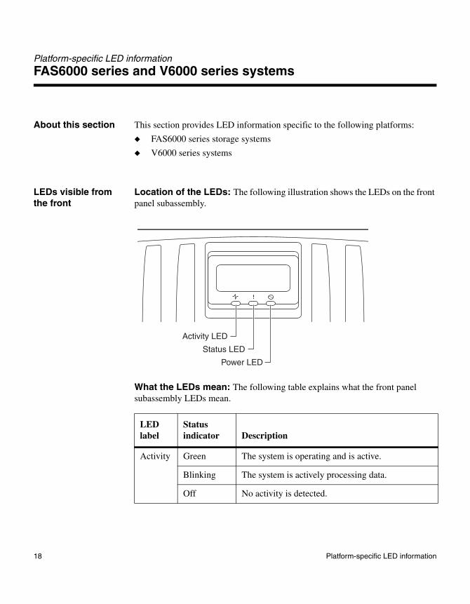
LEDs visible from the front
Location of the LEDs: The following illustration shows the LEDs on the front panel subassembly.
What the LEDs mean: The following table explains what the front panel subassembly LEDs mean.
LED label
Status indicator Description
Activity Green The system is operating and is active.
Blinking The system is actively processing data.
Off No activity is detected.
Activity LED
Status LED
Power LED
18 Platform-specific LED information

LEDs visible from the back
Location of the LEDs: The following illustration shows the location of the following onboard port LEDs on the system backplane:
◆ Fibre Channel port LEDs
◆ GBE
◆ RLM LEDs
Status Green The system is operating normally.
Amber The system halted or a fault occurred. The fault is displayed in the LCD.
AttentionThis LED remains lit during boot, while the operating system loads.
Power Green The system is receiving power.
Off The system is not receiving power.
LED label
Status indicator Description
GbE LEDs
RLM LEDs Fibre Channelport LEDs
Chapter 2: Interpreting LEDs 19

What the LEDs mean: The following table explains what the LEDs for your onboard ports mean.
Port type
LED type Status indicator Description
Fibre Channel
LNK
(Green)
Off No link with the Fibre Channel is established.
Blinking(FAS6030, FAS6070, V6030, and V6070 systems) A link is established and
communication is happening.Solid(FAS6040, FAS6080, V6040, and V6080 systems)
GbEandRLM
LNK On A valid network connection is established.
Off There is no network connection.
ACT On There is data activity.
Off There is no network activity present.
20 Platform-specific LED information
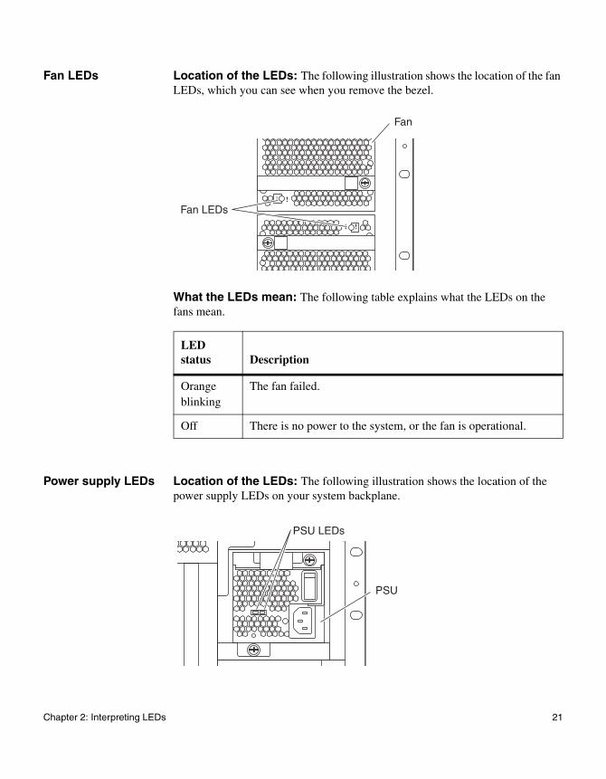
Fan LEDs Location of the LEDs: The following illustration shows the location of the fan LEDs, which you can see when you remove the bezel.
What the LEDs mean: The following table explains what the LEDs on the fans mean.
Power supply LEDs Location of the LEDs: The following illustration shows the location of the power supply LEDs on your system backplane.
LED status Description
Orange blinking
The fan failed.
Off There is no power to the system, or the fan is operational.
Fan
Fan LEDs
PSU LEDs
PSU
Chapter 2: Interpreting LEDs 21
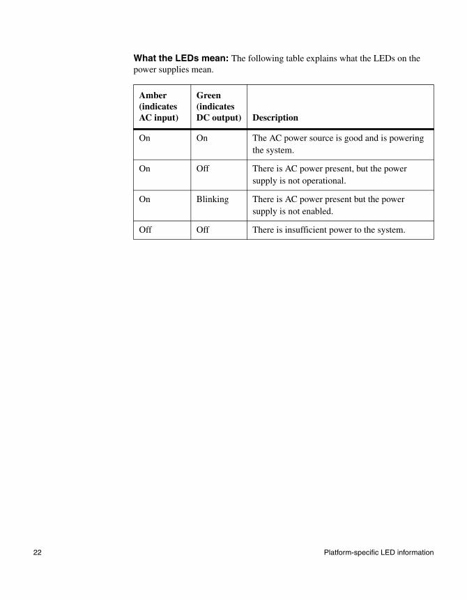
What the LEDs mean: The following table explains what the LEDs on the power supplies mean.
Amber(indicates AC input)
Green(indicates DC output) Description
On On The AC power source is good and is powering the system.
On Off There is AC power present, but the power supply is not operational.
On Blinking There is AC power present but the power supply is not enabled.
Off Off There is insufficient power to the system.
22 Platform-specific LED information
Platform-specific LED information
C1300 NetCache appliances
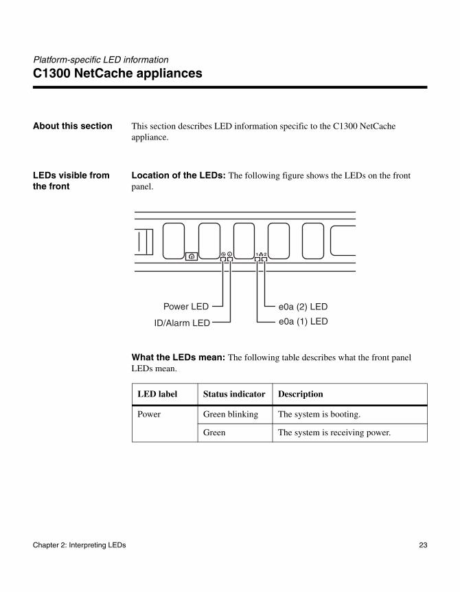
About this section This section describes LED information specific to the C1300 NetCache appliance.
LEDs visible from the front
Location of the LEDs: The following figure shows the LEDs on the front panel.
What the LEDs mean: The following table describes what the front panel LEDs mean.
LED label Status indicator Description
Power Green blinking The system is booting.
Green The system is receiving power.
Power LED
ID/Alarm LED
e0a (2) LED
e0a (1) LED
Chapter 2: Interpreting LEDs 23
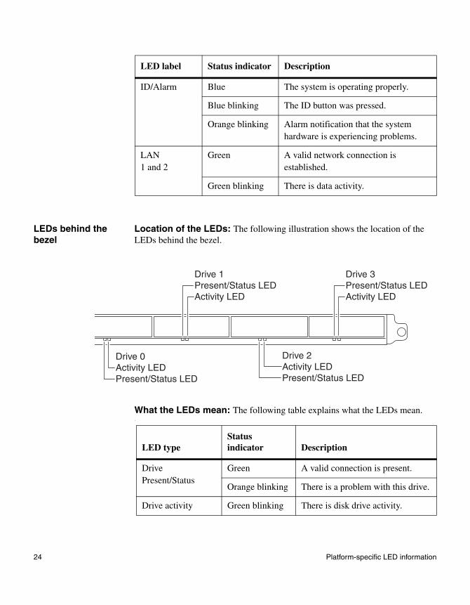
LEDs behind the bezel
Location of the LEDs: The following illustration shows the location of the LEDs behind the bezel.
What the LEDs mean: The following table explains what the LEDs mean..
ID/Alarm Blue The system is operating properly.
Blue blinking The ID button was pressed.
Orange blinking Alarm notification that the system hardware is experiencing problems.
LAN1 and 2
Green A valid network connection is established.
Green blinking There is data activity.
LED label Status indicator Description
Drive 0Activity LEDPresent/Status LED
Drive 1Present/Status LEDActivity LED
Drive 3Present/Status LEDActivity LED
Drive 2Activity LEDPresent/Status LED
LED typeStatus indicator Description
Drive Present/Status
Green A valid connection is present.
Orange blinking There is a problem with this drive.
Drive activity Green blinking There is disk drive activity.
24 Platform-specific LED information
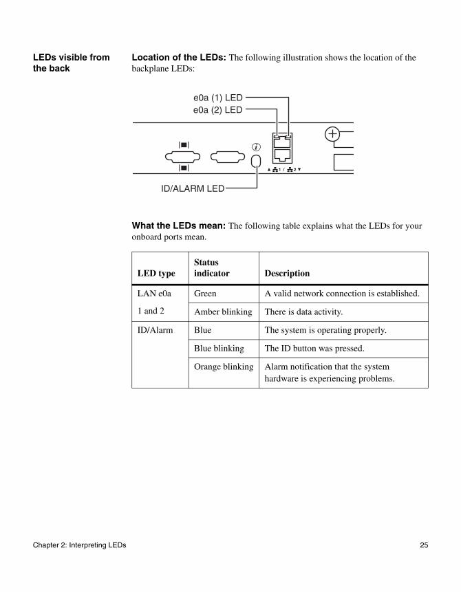
LEDs visible from the back
Location of the LEDs: The following illustration shows the location of the backplane LEDs:
What the LEDs mean: The following table explains what the LEDs for your onboard ports mean.
e0a (2) LEDe0a (1) LED
ID/ALARM LED
LED typeStatus indicator Description
LAN e0a
1 and 2
Green A valid network connection is established.
Amber blinking There is data activity.
ID/Alarm Blue The system is operating properly.
Blue blinking The ID button was pressed.
Orange blinking Alarm notification that the system hardware is experiencing problems.
Chapter 2: Interpreting LEDs 25
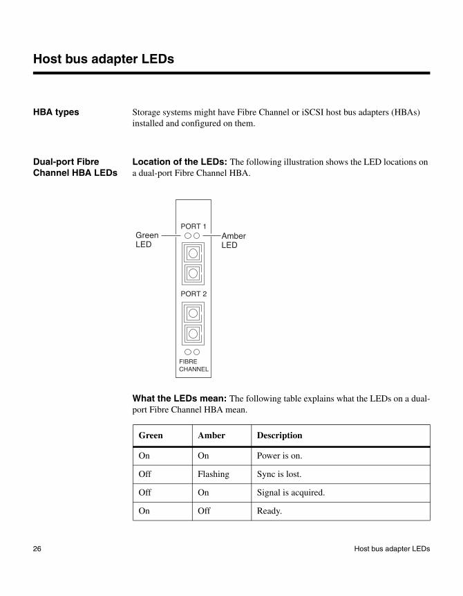
Host bus adapter LEDs
HBA types Storage systems might have Fibre Channel or iSCSI host bus adapters (HBAs) installed and configured on them.
Dual-port Fibre Channel HBA LEDs
Location of the LEDs: The following illustration shows the LED locations on a dual-port Fibre Channel HBA.
What the LEDs mean: The following table explains what the LEDs on a dual-port Fibre Channel HBA mean.
Green Amber Description
On On Power is on.
Off Flashing Sync is lost.
Off On Signal is acquired.
On Off Ready.
PORT 1
FIBRECHANNEL
PORT 2
Amber LED
GreenLED
26 Host bus adapter LEDs

Quad-port, 4-Gb, Fibre Channel HBA LEDs
There are two versions of the quad-port, 4-Gb Fibre Channel HBA. One version has four LEDs, and the other has 12 LEDs. Both HBAs function identically but provide slightly different feedback through the LEDs.
(Four-LED version) Location of the LEDs: The following illustration shows the location of LEDs on a quad-port, 4-Gb, Fibre Channel HBA.
Flashing Off 4 seconds solid followed by one flash: 1-Gb link speed.
4 seconds solid green link followed by two flashes: 2-Gb link speed.
Flashing Flashing Adapter firmware error has been detected.
Green Amber Description
Port A*
Port C*
Port D*
Port A LEDPort C LED Port D LED
Port B LED
Port B*
* Ports in this drawing are labeled as identified by Data ONTAP software.
Chapter 2: Interpreting LEDs 27
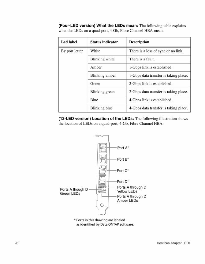
(Four-LED version) What the LEDs mean: The following table explains what the LEDs on a quad-port, 4-Gb, Fibre Channel HBA mean.
(12-LED version) Location of the LEDs: The following illustration shows the location of LEDs on a quad-port, 4-Gb, Fibre Channel HBA.
Led label Status indicator Description
By port letter White There is a loss of sync or no link.
Blinking white There is a fault.
Amber 1-Gbps link is established.
Blinking amber 1-Gbps data transfer is taking place.
Green 2-Gbps link is established.
Blinking green 2-Gbps data transfer is taking place.
Blue 4-Gbps link is established.
Blinking blue 4-Gbps data transfer is taking place.
Port B*
Port C*
Port D*
Ports A through DYellow LEDsPorts A through DAmber LEDs
Ports A though DGreen LEDs
Port A*
* Ports in this drawing are labeled as identified by Data ONTAP software.
28 Host bus adapter LEDs

(12-LED version) What the LEDs mean: The following table explains what the LEDs on a quad-port, 4-Gb, Fibre Channel HBA mean.
Cabling and support rules: The quad-port, 4-Gb, Fibre Channel HBA supports all NetApp Fibre Channel disk devices, subject to current loop mixing restrictions, as well as third-party Fibre Channel tape devices and libraries. You can mix Fibre Channel disk shelves and Fibre Channel tape devices on the same HBA. You must cable them by port pairs of A&B and C&D.
The following are not supported by the HBA or do not support this HBA:
◆ Fabric-attached MetroCluster configurations
◆ V-Series systems
◆ HBA target mode
The following table shows possible cabling combinations by port and device.
Yellow LEDs
Green LEDs
Amber LEDs Description
Off Power is off.
On Power is on (before firmware initialization).
Flashing Power is on (after firmware initialization).
All LEDs alternately flashing A firmware error is detected.
Off Off On 1-Gbps link is established.
Off Off Flashing 1-Gbps data transfer is taking place.
Off On Off 2-Gbps link is established.
Off Flashing Off 2-Gbps data transfer is taking place.
On Off Off 4-Gbps link is established.
Flashing Off Off 4-Gbps data transfer is taking place.
Ports A&B Ports C&D
Disk shelves Disk shelves
Disk shelves Tape/library devices
Tape/library devices Disk shelves
Chapter 2: Interpreting LEDs 29

Dual-port, 4-Gb, target mode, Fibre Channel HBA LEDs
Location of the LEDs: The following illustration shows the location of LEDs on a dual-port, 4-Gb, target mode Fibre Channel HBA.
What the LEDs mean: The following table explains what the LEDs on the HBA mean.
Tape/library devices Tape/library devices
Ports A&B Ports C&D
Yellow Green Amber Description
Off Off Off Power is off.
On On On Power is on, before firmware initialization.
Flashing Flashing Flashing Power is on, after firmware initialization.
LEDs flashing alternately A firmware error is detected.
Off Off On/ Flashing
1-Gbps link/I/O is established.
YGA
AGY
TXRX
TXRX
Port a
Port b
30 Host bus adapter LEDs
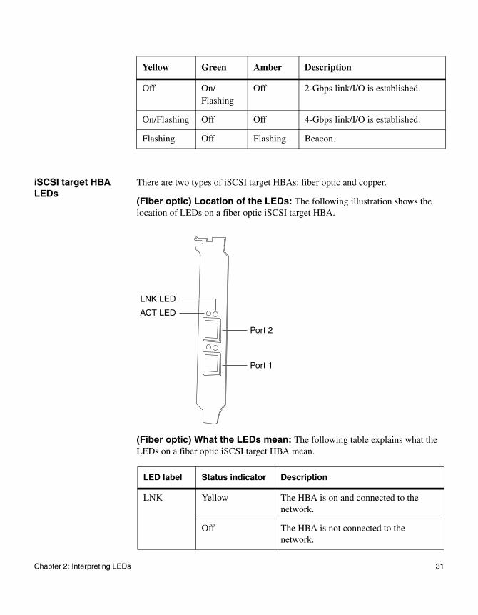
iSCSI target HBA LEDs
There are two types of iSCSI target HBAs: fiber optic and copper.
(Fiber optic) Location of the LEDs: The following illustration shows the location of LEDs on a fiber optic iSCSI target HBA.
(Fiber optic) What the LEDs mean: The following table explains what the LEDs on a fiber optic iSCSI target HBA mean.
Off On/ Flashing
Off 2-Gbps link/I/O is established.
On/Flashing Off Off 4-Gbps link/I/O is established.
Flashing Off Flashing Beacon.
Yellow Green Amber Description
LED label Status indicator Description
LNK Yellow The HBA is on and connected to the network.
Off The HBA is not connected to the network.
ACT LED
LNK LED
Port 2
Port 1
Chapter 2: Interpreting LEDs 31

(Copper) Location of the LEDs: The following illustration shows the location of LEDs on a copper iSCSI target HBA.
(Copper) What the LEDs mean: The following table explains what the LEDs on a copper iSCSI target HBA mean.
ACT Green A connection is established.
Blinking green There is data activity.
LED Label Status Indicator Description
Speed Green The HBA is running at 1 Gbps.
Off The HBA is not running at 1 Gbps.
ACT Amber A connection is established.
Blinking amber There is data activity.
LED label Status indicator Description
Speed LED
Port 2
ACT LED
Port 1
32 Host bus adapter LEDs
GbE NIC LEDs
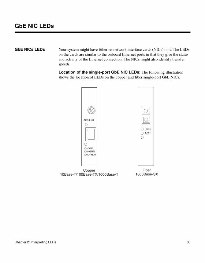
GbE NICs LEDs Your system might have Ethernet network interface cards (NICs) in it. The LEDs on the cards are similar to the onboard Ethernet ports in that they give the status and activity of the Ethernet connection. The NICs might also identify transfer speeds.
Location of the single-port GbE NIC LEDs: The following illustration shows the location of LEDs on the copper and fiber single-port GbE NICs.
LNKACT
Fiber 1000Base-SX
1000=YLW
Copper 10Base-T/100Base-TX/1000Base-T
100=GRN10=OFF
ACT/LNK
Chapter 2: Interpreting LEDs 33
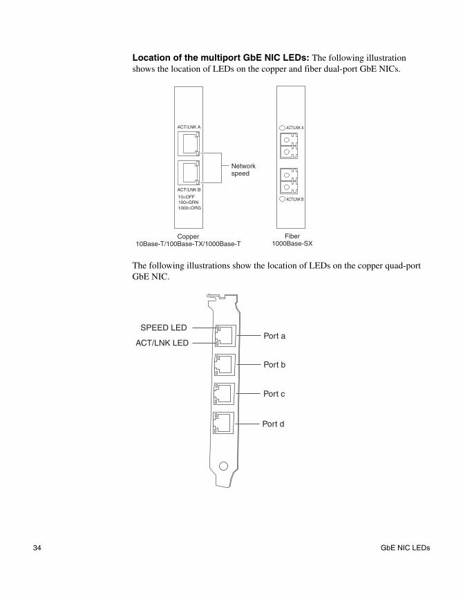
Location of the multiport GbE NIC LEDs: The following illustration shows the location of LEDs on the copper and fiber dual-port GbE NICs.
The following illustrations show the location of LEDs on the copper quad-port GbE NIC.
Fiber 1000Base-SX
Copper 10Base-T/100Base-TX/1000Base-T
Network speed
1000=ORG100=GRN10=OFF
ACT/LNK A
ACT/LNK B
ACT/LNK A
ACT/LNK B
SPEED LED
ACT/LNK LEDPort a
Port b
Port c
Port d
34 GbE NIC LEDs

What the copper GbE NIC LEDs mean: The following table explains what the LEDs on a multiport GbE NIC mean.
AttentionThe LEDs on the quad-port copper GbE NIC are the same as those on the dual-port copper GbE NIC.
What the fiber GbE NIC LEDs mean: The following table explains what the LEDs on the fiber GbE NIC mean.
LED type Status indicator Description
ACT/LNK Green A valid network connection is established.
Blinking greenor blinking amber
There is data activity.
Off There is no network connection.
10=OFF
100=GRN
1000=YLWor1000=ORG
Off Data transmits at 10 Mbps.
Green Data transmits at 100 Mbps.
Yellow(single-port)Orange(multiport)
Data transmits at 1000 Mbps.
LED typeStatus indicator Description
LNK On A valid network connection is established.
Off There is no network connection.
ACT On There is data activity.
Off There is no network activity present.
Chapter 2: Interpreting LEDs 35
TCP offload engine NIC LEDs
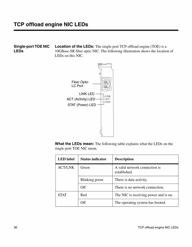
Single-port TOE NIC LEDs
Location of the LEDs: The single-port TCP offload engine (TOE) is a 10GBase-SR fiber optic NIC. The following illustration shows the location of LEDs on this NIC.
What the LEDs mean: The following table explains what the LEDs on the single-port TOE NIC mean.
Fiber Optic LC Port
LINK LED
ACT (Activity) LED
STAT (Power) LED
LINK
ACT
STAT
LED label Status indicator Description
ACT/LNK Green A valid network connection is established.
Blinking green There is data activity.
Off There is no network connection.
STAT Red The NIC is receiving power and is on.
Off The operating system has booted.
36 TCP offload engine NIC LEDs

Dual-port TOE NIC LEDs, 10GBase-SR
Location of the LEDs: This 10-Gb TOE NIC is a 10GBase-SR fiber optic NIC. The following illustration shows the location of LEDs on this NIC.
What the LEDs mean: The following table explains what the LEDs on this dual-port TOE NIC mean.
LED label Status indicator Description
LINK/ACT Green A valid network connection is established.
Blinking amber There is data activity.
Off There is no network connection present.
Fiber Optic LCPort A
Fiber Optic LCPort B
LINK/ACT LED,Port A
LINK/ACT LED,Port B
Chapter 2: Interpreting LEDs 37

Dual-port TOE NIC LEDs, 10GBase-CX4
Location of the LEDs: this 10-Gb TOE NIC is a 10GBase-CX4 NIC. The following illustration shows the location of LEDs on this NIC.
What the LEDs mean: The following table explains what the LEDs on this dual-port TOE NIC mean.
NoteThe 10GBase-CX4 dual-port TOE NIC is for use only on storage systems running Data ONTAP 10.0.3 or later.
LED label Status Indicator Description
LINK/ACT Green A valid network connection is established.
Blinking green There is data activity.
Off There is no network connection present.
Port A
CX4
LINK/ACT
Port B
LINK/ACT
LINK/ACT LED A
LINK/ACT LED B
38 TCP offload engine NIC LEDs
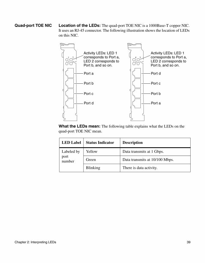
Quad-port TOE NIC Location of the LEDs: The quad-port TOE NIC is a 1000Base-T copper NIC. It uses an RJ-45 connector. The following illustration shows the location of LEDs on this NIC.
What the LEDs mean: The following table explains what the LEDs on the quad-port TOE NIC mean.
LED Label Status Indicator Description
Labeled by port number
Yellow Data transmits at 1 Gbps.
Green Data transmits at 10/100 Mbps.
Blinking There is data activity.
1 2
3 4
Port d
Port c
Port b
Port a
Activity LEDs: LED 1 corresponds to Port a,LED 2 corresponds to Port b, and so on.
4 3
2 1
Port a
Port b
Port c
Port d
Activity LEDs: LED 1 corresponds to Port a,LED 2 corresponds to Port b, and so on.
Chapter 2: Interpreting LEDs 39
NVRAM5 and NVRAM6 adapter LEDs
About NVRAM5 and NVRAM6
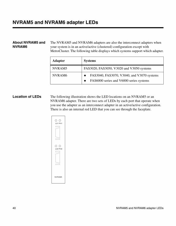
The NVRAM5 and NVRAM6 adapters are also the interconnect adapters when your system is in an active/active (clustered) configuration except with MetroCluster. The following table displays which systems support which adapter.
Location of LEDs The following illustration shows the LED locations on an NVRAM5 or an NVRAM6 adapter. There are two sets of LEDs by each port that operate when you use the adapter as an interconnect adapter in an active/active configuration. There is also an internal red LED that you can see through the faceplate.
Adapter Systems
NVRAM5 FAS3020, FAS3050, V3020 and V3050 systems
NVRAM6 ◆ FAS3040, FAS3070, V3040, and V3070 systems
◆ FAS6000 series and V6000 series systems
NVRAM5
L02 PH2
L01 PH1
40 NVRAM5 and NVRAM6 adapter LEDs

What the LEDs mean
The following table explains what the LEDs on an NVRAM5 or NVRAM6 adapter mean.
LED type Indicator Status Description
Internal Red Blinking There is valid data in the NVRAM5 or NVRAM6.
AttentionThis might occur if your system did not shut down properly, as in the case of a power failure or panic. The data is replayed when the system boots up again.
PH1 Green On The physical connection is working.
Off No physical connection exists.
LO1 Yellow On The logical connection is working.
Off No logical connection exists.
Chapter 2: Interpreting LEDs 41
NVRAM5 and NVRAM6 media converter LEDs
About the media converter
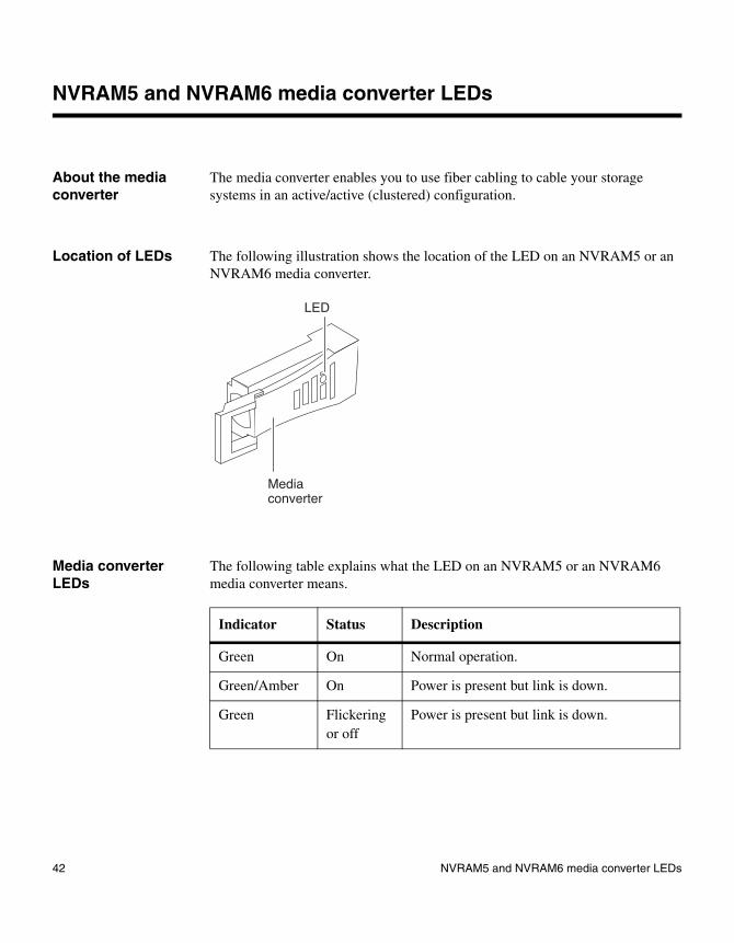
The media converter enables you to use fiber cabling to cable your storage systems in an active/active (clustered) configuration.
Location of LEDs The following illustration shows the location of the LED on an NVRAM5 or an NVRAM6 media converter.
Media converter LEDs
The following table explains what the LED on an NVRAM5 or an NVRAM6 media converter means.
Media converter
LED
Indicator Status Description
Green On Normal operation.
Green/Amber On Power is present but link is down.
Green Flickering or off
Power is present but link is down.
42 NVRAM5 and NVRAM6 media converter LEDs

Chapter 3: Startup error messages
3
Startup error messagesAbout this chapter This chapter lists error messages you might encounter during the boot process.
Topics in this chapter
This chapter discusses the following topics:
◆ “Types of startup error messages” on page 44
◆ “POST error messages” on page 47
◆ “Boot error messages” on page 68
43

Types of startup error messages
Startup sequence When you apply power to your storage system, it verifies the hardware that is in the system, loads the operating system, and displays two types of startup informational and error messages on the system console:
◆ Power-on self-test (POST) messages
◆ Boot messages
CFE and LOADER messages
CFE and LOADER messages occur when an error occurs when the CFE and LOADER run through the POST. This happens before the Data ONTAP software is loaded.
POST messages POST is a series of tests run from the motherboard PROM. These tests check the hardware on the motherboard and differ depending on your system configuration. POST messages appear on the system console.
The following series of messages are examples of POST messages displayed on the console on a system that uses CFE. LOADER displays similar messages.
Header:
CFE version 2.0.0 based on Broadcom CFE: 1.0.40
Copyright (C) 2000,2001,2002,2003 Broadcom Corporation.
Portions Copyright (c) 2002-2005 Network Appliance, Inc.
CPU type 0xF29: 2800MHz
Total memory: 0x80000000 bytes (2048MB)
Starting AUTOBOOT press any key to abort...
Loading....
Entry at...
Starting program...
Press CTRL-C for special boot menu
44 Types of startup error messages

NoteYour storage system LCD, where applicable, displays only the POST messages without the preceding header.
Boot messages After the boot is successfully completed, your storage system loads the operating system. The following message is an example of the boot message that appears on the system console of a FAS3000 storage system at first boot.
NoteThe exact boot messages that appear on your system console depend on your system configuration.
NetApp Release 7.0.1X19: Sun Apr 10 03:04:35 PDT 2005
Copyright (c) 1992-2005 Network Appliance, Inc.
Starting boot on Wed Apr 13 15:30:51 GMT 2005
NetApp Release 7.0.1: Sun Apr 10 03:04:35 PDT 2005
System ID: xxxxxxxxxx
System Serial Number: xxxxxx
System Rev: X0
NetApp Release 7.0.1X19: Sun Apr 10 03:04:35 PDT 2005
System ID: 0101165550
System Serial Number: 1045937
System Rev: B0
slot 0: System Board
Processors: 2
Memory Size: 2048 MB
Remote LAN Module Status: Online
slot 0: Dual 10/100/1000 Ethernet Controller VI
e0a MAC Address: 00:a0:98:02:44:5a (auto-1000t-fd-up)
e0b MAC Address: 00:a0:98:02:44:5b (auto-unknown-cfg_down)
e0c MAC Address: 00:a0:98:02:44:58 (auto-unknown-cfg_down)
Chapter 3: Startup error messages 45

e0d MAC Address: 00:a0:98:02:44:59 (auto-unknown-cfg_down)
slot 0: FC Host Adapter 0a
3 Disks: 204.0GB
1 shelf with LRC
slot 0: FC Host Adapter 0b
slot 0: FC Host Adapter 0c
slot 0: FC Host Adapter 0d
slot 0: SCSI Host Adapter 0e
slot 0: NetApp ATA/IDE Adapter 0f (0x000001f0)
0f.0 245MB
slot 1: NVRAM
Memory Size: 512 MB
Please enter the new hostname []:
Types of startup error messages
You might encounter two groups of startup error messages during the boot process:
◆ POST error messages
◆ Boot error messages
Both error message types are displayed on the system console, and an e-mail notification is sent out by your remote management subsystem, if it is configured to do so.
For detailed information
For a detailed list of the startup error messages, see the following sections:
◆ “POST error messages” on page 47
◆ “Boot error messages” on page 68
46 Types of startup error messages

POST error messages
POST error messages
The following section describes POST error messages specific to the following platforms:
◆ FAS6000 series storage systems and V6000 series systems
◆ FAS3040 and FAS3070 storage systems and V3040 and V3070 systems
◆ FAS3020 and FAS3050 storage systems and V3020 and V3050 systems
◆ C2300 and C3300 NetCache appliances
◆ C1300 NetCache appliances
Chapter 3: Startup error messages 47

POST error messages
FAS3020/V3020 and FAS3050/V3050 systems, and C2300 and C3300 NetCache appliances
POST error messages
The following table describes POST error messages that might appear on the system console if your storage system encounters errors while CFE initiates the hardware.
AttentionAlways power-cycle your storage system when you receive any of the following errors. If the system repeats the error message, follow the corrective action for that error message.
NoteThere is an LED next to each DIMM on the motherboard. When a DIMM fails, the LED lights help you find the failed DIMM.
Error message or code Description Corrective action
Memory init failure: Data segment does not compare at XXXX
XXXX denotes memory address. The CFE failed to initialize the system memory properly.
1. Make sure that the DIMM is supported.
2. Make sure that the DIMM is seated properly.
3. Replace the DIMM if the problem persists.
Unsupported system bus speed 0xXXXX defaulting to 1000Mhz
The CFE detects an unsupported DIMM.
1. Make sure that the DIMM is seated properly.
2. Replace the DIMM if the problem persists.
No Memory found The CFE cannot detect the system DIMMs.
1. Make sure that the DIMM is seated properly and power- cycle your storage system.
2. Replace the DIMM if the problem persists.
48 POST error messages

Abort Autoboot–POST Failure(s): MEMORY
The memory test failed. 1. Make sure that DIMMs are seated properly, then power- cycle your storage system.
2. Replace the DIMM if the problem persists.
Abort Autoboot–POST Failure(s): RTC, RTC_IO
The CFE cannot read the real-time clock (RTC_IO) or the RTC date is invalid (RTC).
1. Use the set date and the set time command to set the date and time.
2. Make sure that the RTC battery is still good.
Abort Autoboot–POST Failure(s): CPU
At least one CPU fails to start up properly.
1. Power-cycle the system to see whether the problem persists.
2. Replace the motherboard tray if the problem persists.
Abort Autoboot–POST Failure(s): UCODE
At least one CPU fails to load the microcode.
1. Power-cycle your system to see whether the problem persists.
2. Replace the motherboard tray if the problem persists.
Invalid FRU EEPROM Checksum
The system backplane or motherboard EEPROM is corrupted.
Call technical support.
Autoboot of primary image aborted
Autoboot of backup image aborted
Autoboot is stopped due to a key being pressed during the autoboot process.
Power-cycle the system and avoid pressing any keys during the autoboot process.
Error message or code Description Corrective action
Chapter 3: Startup error messages 49
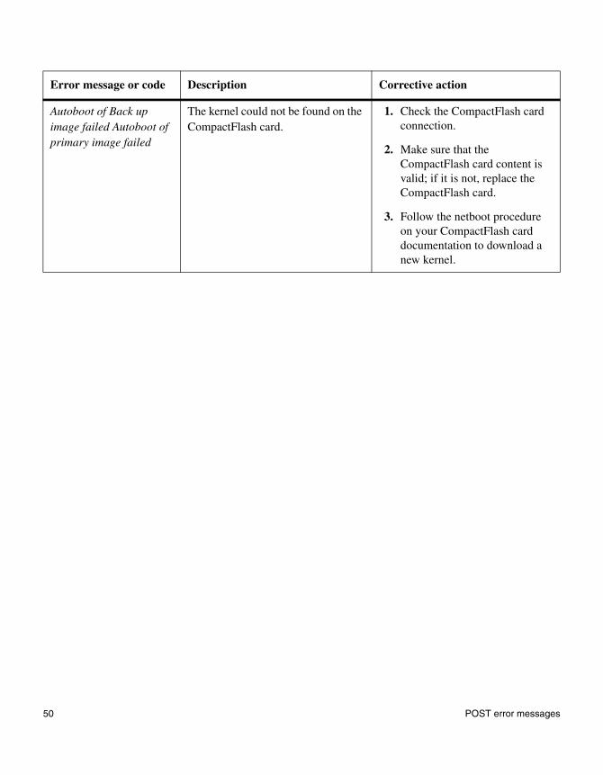
Autoboot of Back up image failed Autoboot of primary image failed
The kernel could not be found on the CompactFlash card.
1. Check the CompactFlash card connection.
2. Make sure that the CompactFlash card content is valid; if it is not, replace the CompactFlash card.
3. Follow the netboot procedure on your CompactFlash card documentation to download a new kernel.
Error message or code Description Corrective action
50 POST error messages

POST error messages
FAS3040/V3040 and FAS3070/V3070 systems, and FAS6000/V6000 series systems
POST error messages
The following table describes POST error messages that might appear on the system console if your system encounters errors while the BIOS and boot loader initiate the hardware.
AttentionAlways power-cycle your system when you receive any of the following errors. If the system repeats the error message, follow the corrective action for that error message.
Error message or code Description Corrective action
0200: Failure Fixed Disk A disk error occurred. Complete the following steps to determine whether the CompactFlash card is bad.
1. Enter the following command at the LOADER> prompt:
boot_diag
2. Select the cf-card test.
If the test shows that the CompactFlash card is bad, replace it.
If the CompactFlash card is good, replace the motherboard.
Chapter 3: Startup error messages 51
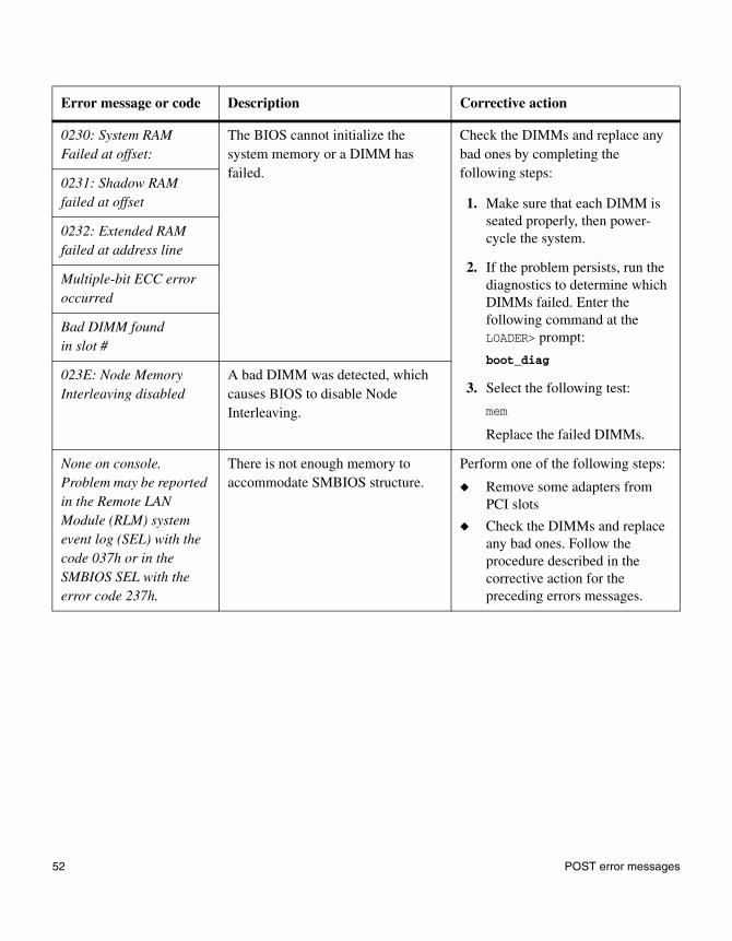
0230: System RAM Failed at offset:
The BIOS cannot initialize the system memory or a DIMM has failed.
Check the DIMMs and replace any bad ones by completing the following steps:
1. Make sure that each DIMM is seated properly, then power- cycle the system.
2. If the problem persists, run the diagnostics to determine which DIMMs failed. Enter the following command at the LOADER> prompt:
boot_diag
3. Select the following test:
mem
Replace the failed DIMMs.
0231: Shadow RAM failed at offset
0232: Extended RAM failed at address line
Multiple-bit ECC error occurred
Bad DIMM found in slot #
023E: Node Memory Interleaving disabled
A bad DIMM was detected, which causes BIOS to disable Node Interleaving.
None on console. Problem may be reported in the Remote LAN Module (RLM) system event log (SEL) with the code 037h or in the SMBIOS SEL with the error code 237h.
There is not enough memory to accommodate SMBIOS structure.
Perform one of the following steps:
◆ Remove some adapters from PCI slots
◆ Check the DIMMs and replace any bad ones. Follow the procedure described in the corrective action for the preceding errors messages.
Error message or code Description Corrective action
52 POST error messages

0241: Agent Read Timeout
Timeout occurs when BIOS tries to read or write information through System Management Bus (SMBUS) or Inter-Integrated Circuit (I2C).
Run the Agent diagnostic test.
1. Enter the following command at the LOADER> prompt:
boot_diag
2. Select and run the following tests:
agent
2
6
3. Select and run the following tests:
mb
2
8
Error message or code Description Corrective action
Chapter 3: Startup error messages 53

0242: Invalid FRU information
The information from the field-replaceable unit’s (FRU’s) Electrically Erasable Programmable Read-Only Memory (EEPROM) is invalid.
1. Enter the following command at the LOADER> prompt:
boot_diag
2. To determine the FRU involved, select the following tests:
mb
74
3. Check whether the FRU’s model name, serial number, part number, and revision are correct in one of the following ways:
❖ Visually inspect the FRU.
❖ Look for error messages indicating that the FRU information is invalid or could not be read.
4. Contact technical support if you suspect a misprogrammed FRU.
0250: System battery is dead–Replace and run SETUP
The real-time clock (RTC) battery is dead.
1. Reboot the system.
2. If the problem persists, replace the RTC battery
3. Reset the RTC.
0251: System CMOS checksum bad–Default configuration used
CMOS checksum is bad, possibly because the system was reset during BIOS boot or because of a dead real-time clock (RTC) battery.
1. Reboot the system.
2. If the problem persists, replace the RTC battery.
3. Reset the RTC.
Error message or code Description Corrective action
54 POST error messages
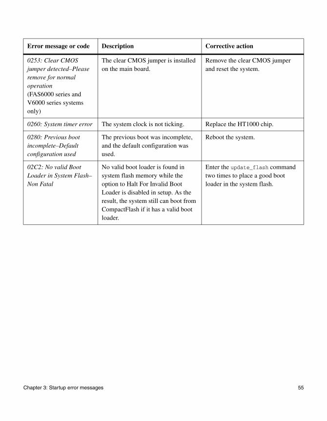
0253: Clear CMOS jumper detected–Please remove for normal operation(FAS6000 series and V6000 series systems only)
The clear CMOS jumper is installed on the main board.
Remove the clear CMOS jumper and reset the system.
0260: System timer error The system clock is not ticking. Replace the HT1000 chip.
0280: Previous boot incomplete–Default configuration used
The previous boot was incomplete, and the default configuration was used.
Reboot the system.
02C2: No valid Boot Loader in System Flash–Non Fatal
No valid boot loader is found in system flash memory while the option to Halt For Invalid Boot Loader is disabled in setup. As the result, the system still can boot from CompactFlash if it has a valid boot loader.
Enter the update_flash command two times to place a good boot loader in the system flash.
Error message or code Description Corrective action
Chapter 3: Startup error messages 55
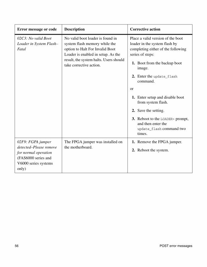
02C3: No valid Boot Loader in System Flash–Fatal
No valid boot loader is found in system flash memory while the option to Halt For Invalid Boot Loader is enabled in setup. As the result, the system halts. Users should take corrective action.
Place a valid version of the boot loader in the system flash by completing either of the following series of steps:
1. Boot from the backup boot image.
2. Enter the update_flash command.
or
1. Enter setup and disable boot from system flash.
2. Save the setting.
3. Reboot to the LOADER> prompt, and then enter the update_flash command two times.
02F9: FGPA jumper detected–Please remove for normal operation(FAS6000 series and V6000 series systems only)
The FPGA jumper was installed on the motherboard.
1. Remove the FPGA jumper.
2. Reboot the system.
Error message or code Description Corrective action
56 POST error messages

02FA: Watchdog Timer Reboot (PciInit)
The watchdog times out while BIOS is doing PCI initialization.
1. Power-cycle the system a few times or reset the system through the Remote LAN Module (RLM).
2. If the problem persists, check the PCI interface. At the LOADER> prompt, enter the following command:
boot_diags
3. Select the following tests:
mb
4
71
4. Replace the motherboard if the diagnostics show a problem.
02FB: Watchdog Timer Reboot (MemTest)(FAS6000 series and V6000 series systems only)
The watchdog times out while BIOS is testing the extended memory.
1. Power-cycle the system a few times or reset the system through the Remote LAN Module (RLM).
2. If the problem persists, check the memory interface. At the LOADER> prompt, enter the following command:
boot_diags
3. Select the following tests:
mem
1
4. Replace the DIMMs if the diagnostics show a problem.
5. Replace the motherboard if the problem persists.
Error message or code Description Corrective action
Chapter 3: Startup error messages 57
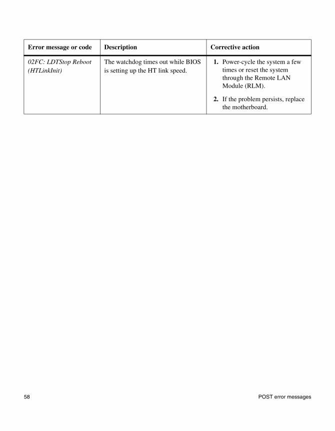
02FC: LDTStop Reboot (HTLinkInit)
The watchdog times out while BIOS is setting up the HT link speed.
1. Power-cycle the system a few times or reset the system through the Remote LAN Module (RLM).
2. If the problem persists, replace the motherboard.
Error message or code Description Corrective action
58 POST error messages
POST error messages
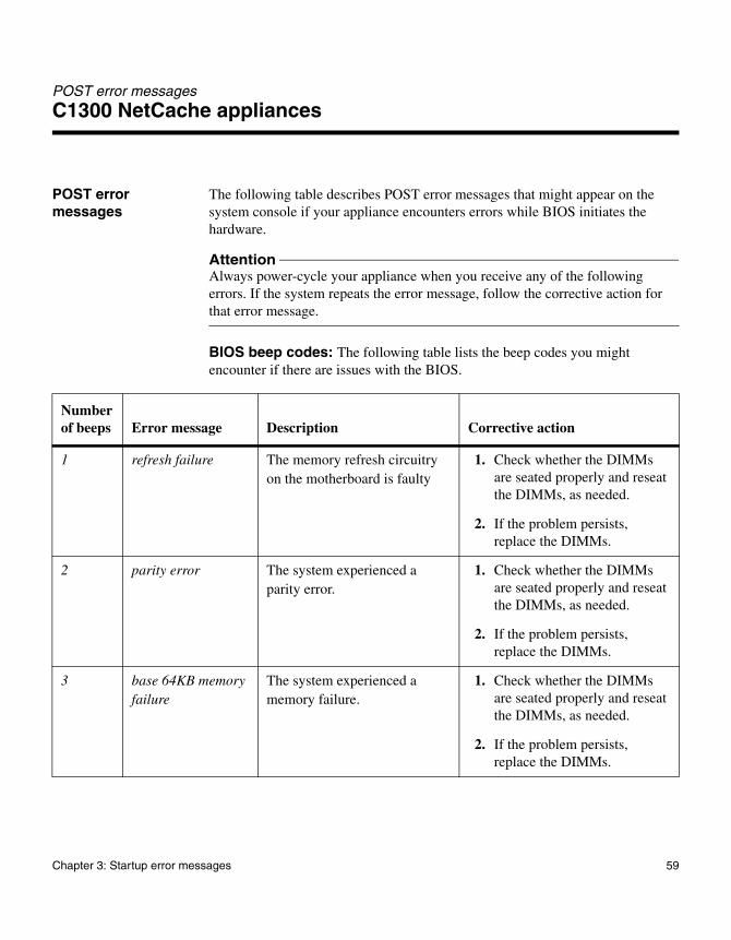
C1300 NetCache appliances
POST error messages
The following table describes POST error messages that might appear on the system console if your appliance encounters errors while BIOS initiates the hardware.
AttentionAlways power-cycle your appliance when you receive any of the following errors. If the system repeats the error message, follow the corrective action for that error message.
BIOS beep codes: The following table lists the beep codes you might encounter if there are issues with the BIOS.
Number of beeps Error message Description Corrective action
1 refresh failure The memory refresh circuitry on the motherboard is faulty
1. Check whether the DIMMs are seated properly and reseat the DIMMs, as needed.
2. If the problem persists, replace the DIMMs.
2 parity error The system experienced a parity error.
1. Check whether the DIMMs are seated properly and reseat the DIMMs, as needed.
2. If the problem persists, replace the DIMMs.
3 base 64KB memory failure
The system experienced a memory failure.
1. Check whether the DIMMs are seated properly and reseat the DIMMs, as needed.
2. If the problem persists, replace the DIMMs.
Chapter 3: Startup error messages 59
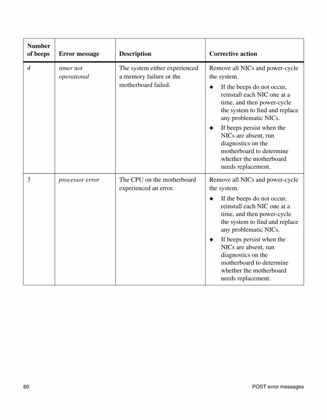
4 timer not operational
The system either experienced a memory failure or the motherboard failed.
Remove all NICs and power-cycle the system.
◆ If the beeps do not occur, reinstall each NIC one at a time, and then power-cycle the system to find and replace any problematic NICs.
◆ If beeps persist when the NICs are absent, run diagnostics on the motherboard to determine whether the motherboard needs replacement.
5 processor error The CPU on the motherboard experienced an error.
Remove all NICs and power-cycle the system.
◆ If the beeps do not occur, reinstall each NIC one at a time, and then power-cycle the system to find and replace any problematic NICs.
◆ If beeps persist when the NICs are absent, run diagnostics on the motherboard to determine whether the motherboard needs replacement.
Number of beeps Error message Description Corrective action
60 POST error messages

6 8042-gate A20 failure
The keyboard controller (8042) might be functioning incorrectly. The BIOS cannot switch to protected mode.
Remove all NICs and power-cycle the system.
◆ If the beeps do not occur, reinstall each NIC one at a time, and then power-cycle the system to find and replace any problematic NICs.
◆ If beeps persist when the NICs are absent, run diagnostics on the motherboard to determine whether the motherboard needs replacement.
7 processor exception interrupt error
The CPU generated an exception interrupt.
Remove all NICs and power-cycle the system.
◆ If the beeps do not occur, reinstall each NIC one at a time, and then power-cycle the system to find and replace any problematic NICs.
◆ If beeps persist when the NICs are absent, run diagnostics on the motherboard to determine whether the motherboard needs replacement.
Number of beeps Error message Description Corrective action
Chapter 3: Startup error messages 61

8 display memory read/write error
The system video adapter is either missing or its memory is faulty. This is not a fatal error.
Remove all NICs and power-cycle the system.
◆ If the beeps do not occur, reinstall each NIC one at a time, and then power-cycle the system to find and replace any problematic NICs.
◆ If beeps persist when the NICs are absent, run diagnostics on the motherboard to determine whether the motherboard needs replacement.
9 ROM checksum error
The ROM checksum value does not match the value encoded in the BIOS.
Remove all NICs and power-cycle the system.
◆ If the beeps do not occur, reinstall each NIC one at a time, and then power-cycle the system to find and replace any problematic NICs.
◆ If beeps persist when the NICs are absent, run diagnostics on the motherboard to determine whether the motherboard needs replacement.
Number of beeps Error message Description Corrective action
62 POST error messages

BIOS error messages: The following table lists the error messages you might encounter if there are issues with the BIOS.
10 CMOS shutdown register read/write error
The shutdown register for CMOS RAM failed.
Remove all NICs and power-cycle the system.
◆ If the beeps do not occur, reinstall each NIC one at a time, and then power-cycle the system to find and replace any problematic NICs.
◆ If beeps persist when the NICs are absent, run diagnostics on the motherboard to determine whether the motherboard needs replacement.
11 Cache error/external cache bad
The external cache is faulty. Remove all NICs and power-cycle the system.
◆ If the beeps do not occur, reinstall each NIC one at a time, and then power-cycle the system to find and replace any problematic NICs.
◆ If beeps persist when the NICs are absent, run diagnostics on the motherboard to determine whether the motherboard needs replacement.
Number of beeps Error message Description Corrective action
Chapter 3: Startup error messages 63

Error message or code Description Corrective action
Gate20 error The BIOS cannot control the gate A20 function, which controls access of memory over 1 MB.
Run diagnostics on the motherboard.
If the problem persists, replace the motherboard.
Multi-bit ECC error A multiple bit corruption of memory has occurred that cannot be corrected.
Replace the DIMMs.
Parity error A fatal parity error has occurred. The system halts after displaying this message.
1. Run diagnostics on all components.
2. If this message persists, call technical support.
Boot failure The BIOS could not boot from a particular device. This message is usually followed by other information concerning the device.
1. Wait for the message that follows, which provides more information.
2. Replace the device specified, and then power-cycle the system.
Invalid boot diskette A diskette was found in the drive, but it is not configured as a bootable diskette.
1. Power-cycle the system.
2. If the problem, persists call technical support.
Drive not ready The BIOS cannot access the drive because it was not ready for data transfer. This is often reported by drives when no media is present.
1. Power-cycle the system.
2. If the problem, persists call technical support.
A: drive failure
B: drive failure
The BIOS failed to configure the specified drive during POST.
1. Power-cycle the system.
2. Replace the specified drive.
Insert BOOT diskette in A The BIOS could not boot from the A drive.
Replace the disk drive.
64 POST error messages
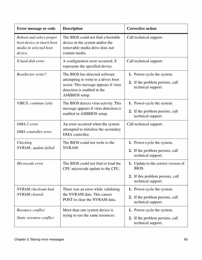
Reboot and select proper boot device or insert boot media in selected boot device.
The BIOS could not find a bootable device in the system and/or the removable media drive does not contain media.
Call technical support.
X hard disk error A configuration error occurred; X represents the specified device.
Call technical support.
BootSector write!! The BIOS has detected software attempting to write to a drives boot sector. This message appears if virus detection is enabled in the AMIBIOS setup.
1. Power-cycle the system.
2. If the problem persists, call technical support.
VIRUS: continue (y/n) The BIOS detects virus activity. This message appears if virus detection is enabled in AMIBIOS setup.
1. Power-cycle the system.
2. If the problem persists, call technical support.
DMA-2 error
DMA controller error
An error occurred when the system attempted to initialize the secondary DMA controller.
Call technical support.
Checking NVRAM...update failed
The BIOS could not write to the NVRAM.
1. Power-cycle the system.
2. If the problem persists, call technical support.
Microcode error The BIOS could not find or load the CPU microcode update to the CPU.
1. Update to the correct version of BIOS.
2. If this problem persists, call technical support.
NVRAM checksum bad, NVRAM cleared
There was an error while validating the NVRAM data. This causes POST to clear the NVRAM data.
1. Power-cycle the system.
2. If the problem persists, call technical support.
Resource conflict
Static resource conflict
More than one system device is trying to use the same resources.
1. Power-cycle the system.
2. If the problem persists, call technical support.
Error message or code Description Corrective action
Chapter 3: Startup error messages 65

NVRAM ignored
NVRAM bad
There was an error in configuring the NVRAM.
1. Power-cycle the system.
2. If the problem persists, call technical support.
PCI I/O conflict
PCI ROM conflict
PCI IRQ conflict
A PCI adapter generated an I/O resource conflict when configured by BIOS.
1. Power-cycle the system.
2. If the problem persists, call technical support.
PCI IRQ routing table error
There was an error in configuring a PCI device.
1. Power-cycle the system.
2. If the problem persists, call technical support.
Timer error There was an error with initializing the system hardware.
1. Power-cycle the system.
2. If the problem persists, call technical support.
Interrupt controller-N error
The BIOS could not initialize an interrupt controller.
1. Power-cycle the system.
2. If the problem persists, call technical support.
CMOS date/time not set The CMOS date and time are invalid.
1. Power-cycle the system.
2. If the problem persists, call technical support.
CMOS battery low The CMOS battery is low. 1. Power-cycle the system.
2. If the problem persists, call technical support.
CMOS settings wrong The CMOS settings are invalid. 1. Power-cycle the system.
2. If the problem persists, call technical support.
CMOS checksum bad The CMOS data has been changed by a program other than the BIOS.
1. Power-cycle the system.
2. If the problem persists, call technical support.
Error message or code Description Corrective action
66 POST error messages

Keyboard error
Keyboard/interface error
The keyboard controller is not responding when the BIOS attempts to initialize it.
1. Power-cycle the system.
2. If the problem persists, call technical support.
System halted The system was halted. This message appears when a fatal error occurred.
1. Power-cycle the system.
2. If the problem persists, call technical support.
Error message or code Description Corrective action
Chapter 3: Startup error messages 67

Boot error messages
When boot error messages appear
Boot error messages might appear after the hardware passes all POSTs and your storage system begins to load the operating system.
Boot error messages
The following table describes the error messages that might appear on the LCD if your storage system encounters errors while starting up.
Boot error message Explanation Corrective action
Boot device err A CompactFlash card could not be found to boot from.
Insert a valid CompactFlash card.
Cannot initialize labels
When the system tries to create a new file system, it cannot initialize the disk labels.
Usually, you do not need to create and initialize a file system; do so only after consulting technical support.
Cannot read labels When your storage system tries to initialize a new file system, it has a problem reading the disk labels it wrote to the disks.
This problem can be because the system failed to read the disk size, or the written disk labels were invalid
Usually, you do not need to create and initialize a file system; do so only after consulting technical support.
Configuration exceeds max PCI space
The memory space for mapping PCI adapters has been exhausted, because either
◆ There are too many PCI adapters in the system
◆ An adapter is demanding too many resources
Verify that all expansion adapters in your storage system are supported.
Contact technical support for help. Have a list ready of all expansion adapters installed in your storage system.
Dirty shutdown in degraded mode
The file system is inconsistent because you did not shut down the system cleanly when it was in degraded mode.
Contact technical support for instructions about repairing the file system.
68 Boot error messages

DIMM slot # has correctable ECC errors.
The specified DIMM slot has correctable ECC errors.
Run diagnostics on your DIMMs. If the problem persists, replace the specified DIMM.
Disk label processing failed
Your storage system detects that the disk is not in the correct drive bay.
Make sure that the disk is in the correct bay.
Drive %s.%d not supported
%s—The disk number; %d—The disk ID number. The system detects an unsupported disk drive.
1. Remove the drive immediately or the system drops down to the PROM monitor within 30 seconds.
2. Check the System Configuration Guide at http://now.netapp.com to verify support for your disk drive.
Error detection detected too many errors to analyze at once
This message occurs when other error messages occur at the same time.
See the other error messages and their respective corrective actions. If the problem persists, contact technical support.
FC-AL loop down, adapter %d
The system cannot detect the FC-AL loop or adapter.
1. Identify the adapter by entering the following command:
storage show adapter
2. Turn off the power on your storage system and verify that the adapter is properly seated in the expansion slot.
3. Verify that all Fibre Channel cables are connected.
Boot error message Explanation Corrective action
Chapter 3: Startup error messages 69

File system may be scrambled
One of the following errors causes the file system to be inconsistent:
◆ An unclean shutdown when your storage system is in degraded mode and when NVRAM is not working.
Contact technical support to learn how to start the system from a system boot diskette and repair the file system.
◆ The number of disks detected in the disk array is different from the number of disks recorded in the disk labels. The system cannot start when more than one disk is missing.
Make sure that all disks on the system are properly installed in the disk shelves.
◆ The system encounters a read error while reconstructing parity.
Contact technical support for help.
◆ A disk failed at the same time the system crashed.
Contact technical support to learn how to repair the file system.
Halted disk firmware too old
The disk firmware is an old version. Update the disk firmware by entering the following command:
disk_fw_update
Halted: Illegal configuration
Incorrect active/active (cluster) configuration.
1. Check the console for details.
2. Verify that all cables are correctly connected.
Invalid PCI card slot %d
%d—The expansion slot number. The system detects a adapter that is not supported.
Replace the unsupported adapter with an adapter that is included in the System Configuration Guide at http://now.netapp.com.
No disks The system cannot detect any FC-AL disks.
Verify that all disks are properly seated in the drive bays.
No disk controllers The system cannot detect any FC-AL disk controllers.
Turn off your storage system power and verify that all NICs are properly seated in the appropriate expansion slots.
Boot error message Explanation Corrective action
70 Boot error messages

No /etc/rc The /etc/rc file is corrupted. 1. At the hostname> prompt, enter setup.
2. As the system prompts for system configuration information, use the information you recorded in your storage system configuration information worksheet in the Getting Started Guide.
For more information about your storage system setup program, see the appropriate system administration guide.
No /etc/rc, running setup
The system cannot find the /etc/rc file and automatically starts setup.
As the system prompts for system configuration information, use the information you recorded in your storage system configuration information worksheet in the Getting Started Guide.
For more information about your storage system setup program, see the appropriate system administration guide.
No network interfaces The system cannot detect any network interfaces.
1. Turn off the system and verify that all NICs are seated properly in the appropriate expansion slots.
2. Run diagnostics to check the onboard Ethernet port.
If the problem persists, contact technical support.
Boot error message Explanation Corrective action
Chapter 3: Startup error messages 71

NVRAM: wrong pci slot
The system cannot detect the NVRAM adapter.
◆ For a stand-alone FAS3020, FAS3050, V3020, or V3050 system, make sure that the NVRAM adapter is in slot 1.
◆ For a FAS3020, FAS3050, V3020, or V3050 series system in active/active (clustered) configuration, make sure that the NVRAM adapter is in slot 2.
NoteC2300 and C3300 NetCache appliances do not support NVRAM5.
No NVRAM present The system cannot detect the NVRAM adapter.
Make sure that the NVRAM adapter is securely installed in the appropriate expansion slot.
NVRAM #n downrev n—The serial number of the NVRAM adapter. The NVRAM adapter is an early revision that cannot be used with the system.
Check the console for information about which revision of the NVRAM adapter is required. Replace the NVRAM adapter.
Panic: DIMM slot #n has uncorrectable ECC errors. Replace these DIMMS.
The specified DIMM has uncorrectable ECC errors.
Replace the specified DIMM.
This platform is not supported on this release. Please consult the release notes.Please downgrade to a supported release! Shutting down: EOL platform
This platform is not supported on this release. Please consult the release notes for your software.
You must downgrade your software version to a compatible release.
Verify that you have the correct URL for software download.
Boot error message Explanation Corrective action
72 Boot error messages
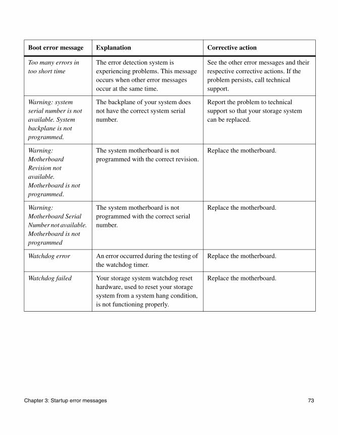
Too many errors in too short time
The error detection system is experiencing problems. This message occurs when other error messages occur at the same time.
See the other error messages and their respective corrective actions. If the problem persists, call technical support.
Warning: system serial number is not available. System backplane is not programmed.
The backplane of your system does not have the correct system serial number.
Report the problem to technical support so that your storage system can be replaced.
Warning: Motherboard Revision not available. Motherboard is not programmed.
The system motherboard is not programmed with the correct revision.
Replace the motherboard.
Warning: Motherboard Serial Number not available. Motherboard is not programmed
The system motherboard is not programmed with the correct serial number.
Replace the motherboard.
Watchdog error An error occurred during the testing of the watchdog timer.
Replace the motherboard.
Watchdog failed Your storage system watchdog reset hardware, used to reset your storage system from a system hang condition, is not functioning properly.
Replace the motherboard.
Boot error message Explanation Corrective action
Chapter 3: Startup error messages 73

74 Boot error messages

Chapter 4: Interpreting EMS and operational error messages
4
Interpreting EMS and operational error messagesAbout this chapter This chapter lists error messages you might encounter during normal operation.
Topics in this chapter
This chapter discusses the following topics:
◆ “FAS2000 series system AutoSupport error messages” on page 76
◆ “EMS error messages” on page 83
◆ “Environmental EMS error messages” on page 98
◆ “SES EMS error messages” on page 108
◆ “Operational error messages” on page 140
75

FAS2000 series system AutoSupport error messages
When AutoSupport error messages appear
The following table describes the AutoSupport error messages that might appear on the FAS2000 series storage system console.
AttentionWhen you remove a power supply on a FAS2000 series storage system, you have two minutes to replace it to prevent possible damage to the controller modules. If you do not replace the power supply within two minutes, the controller modules shut down.
AttentionAfter you remove and replace the NVMEM battery or a DIMM on a FAS2000 series storage system, you need to manually reset the date and time on the controller module after Data ONTAP finishes booting. If your system is in an active/active configuration, you need to reset the date and time on both controller modules.
If you replace a DIMM, you must follow the proper procedure. See Replacing DIMMs in a FAS2000 Series System on the NOW site.
Error message or code Description Corrective action
BATTERY LOW The NVMEM battery is low. The smart battery automatically begins charging. If the battery is not fully charged after 24 hours, the controller module will shut down.
1. Allow the battery time to charge.
2. Replace the battery.
3. If this message persists, call technical support.
BATTERY OVER TEMPERATURE
Battery is over-temperature. 1. Allow the system to cool gradually.
2. If this error persists, replace the battery pack.
76 FAS2000 series system AutoSupport error messages
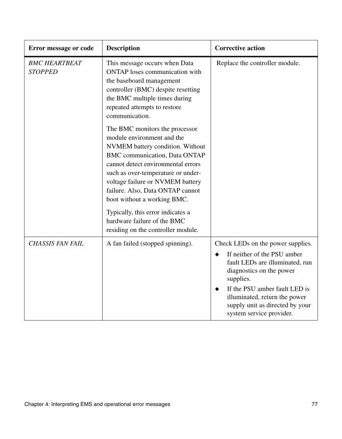
BMC HEARTBEAT STOPPED
This message occurs when Data ONTAP loses communication with the baseboard management controller (BMC) despite resetting the BMC multiple times during repeated attempts to restore communication.
The BMC monitors the processor module environment and the NVMEM battery condition. Without BMC communication, Data ONTAP cannot detect environmental errors such as over-temperature or under-voltage failure or NVMEM battery failure. Also, Data ONTAP cannot boot without a working BMC.
Typically, this error indicates a hardware failure of the BMC residing on the controller module.
Replace the controller module.
CHASSIS FAN FAIL A fan failed (stopped spinning). Check LEDs on the power supplies.
◆ If neither of the PSU amber fault LEDs are illuminated, run diagnostics on the power supplies.
◆ If the PSU amber fault LED is illuminated, return the power supply unit as directed by your system service provider.
Error message or code Description Corrective action
Chapter 4: Interpreting EMS and operational error messages 77
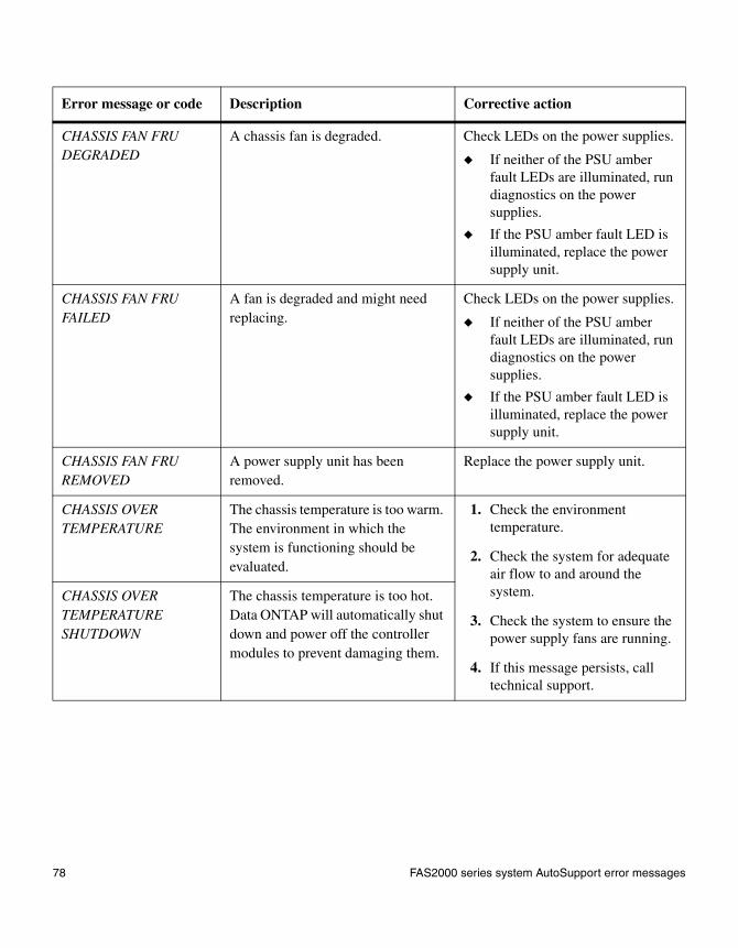
CHASSIS FAN FRU DEGRADED
A chassis fan is degraded. Check LEDs on the power supplies.
◆ If neither of the PSU amber fault LEDs are illuminated, run diagnostics on the power supplies.
◆ If the PSU amber fault LED is illuminated, replace the power supply unit.
CHASSIS FAN FRU FAILED
A fan is degraded and might need replacing.
Check LEDs on the power supplies.
◆ If neither of the PSU amber fault LEDs are illuminated, run diagnostics on the power supplies.
◆ If the PSU amber fault LED is illuminated, replace the power supply unit.
CHASSIS FAN FRU REMOVED
A power supply unit has been removed.
Replace the power supply unit.
CHASSIS OVER TEMPERATURE
The chassis temperature is too warm. The environment in which the system is functioning should be evaluated.
1. Check the environment temperature.
2. Check the system for adequate air flow to and around the system.
3. Check the system to ensure the power supply fans are running.
4. If this message persists, call technical support.
CHASSIS OVER TEMPERATURE SHUTDOWN
The chassis temperature is too hot. Data ONTAP will automatically shut down and power off the controller modules to prevent damaging them.
Error message or code Description Corrective action
78 FAS2000 series system AutoSupport error messages
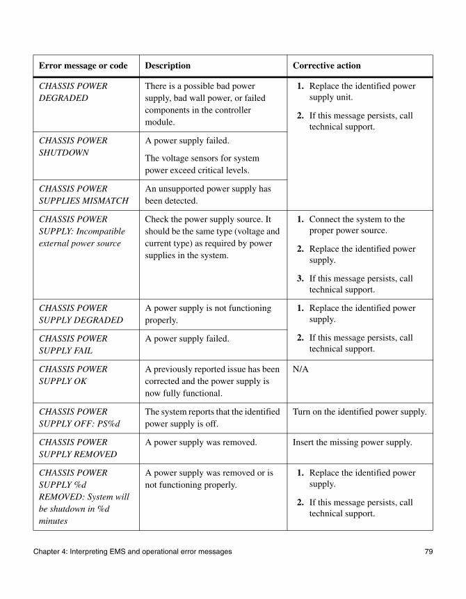
CHASSIS POWER DEGRADED
There is a possible bad power supply, bad wall power, or failed components in the controller module.
1. Replace the identified power supply unit.
2. If this message persists, call technical support.
CHASSIS POWER SHUTDOWN
A power supply failed.
The voltage sensors for system power exceed critical levels.
CHASSIS POWER SUPPLIES MISMATCH
An unsupported power supply has been detected.
CHASSIS POWER SUPPLY: Incompatible external power source
Check the power supply source. It should be the same type (voltage and current type) as required by power supplies in the system.
1. Connect the system to the proper power source.
2. Replace the identified power supply.
3. If this message persists, call technical support.
CHASSIS POWER SUPPLY DEGRADED
A power supply is not functioning properly.
1. Replace the identified power supply.
2. If this message persists, call technical support.
CHASSIS POWER SUPPLY FAIL
A power supply failed.
CHASSIS POWER SUPPLY OK
A previously reported issue has been corrected and the power supply is now fully functional.
N/A
CHASSIS POWER SUPPLY OFF: PS%d
The system reports that the identified power supply is off.
Turn on the identified power supply.
CHASSIS POWER SUPPLY REMOVED
A power supply was removed. Insert the missing power supply.
CHASSIS POWER SUPPLY %d REMOVED: System will be shutdown in %d minutes
A power supply was removed or is not functioning properly.
1. Replace the identified power supply.
2. If this message persists, call technical support.
Error message or code Description Corrective action
Chapter 4: Interpreting EMS and operational error messages 79
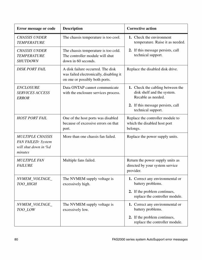
CHASSIS UNDER TEMPERATURE
The chassis temperature is too cool. 1. Check the environment temperature. Raise it as needed.
2. If this message persists, call technical support.
CHASSIS UNDER TEMPERATURE SHUTDOWN
The chassis temperature is too cold. The controller module will shut down in 60 seconds.
DISK PORT FAIL A disk failure occurred. The disk was failed electronically, disabling it on one or possibly both ports.
Replace the disabled disk drive.
ENCLOSURE SERVICES ACCESS ERROR
Data ONTAP cannot communicate with the enclosure services process.
1. Check the cabling between the disk shelf and the system. Recable as needed.
2. If this message persists, call technical support.
HOST PORT FAIL One of the host ports was disabled because of excessive errors on that port.
Replace the controller module to which the disabled host port belongs.
MULTIPLE CHASSIS FAN FAILED: System will shut down in %d minutes
More than one chassis fan failed. Replace the power supply units.
MULTIPLE FAN FAILURE
Multiple fans failed. Return the power supply units as directed by your system service provider.
NVMEM_VOLTAGE_TOO_HIGH
The NVMEM supply voltage is excessively high.
1. Correct any environmental or battery problems.
2. If the problem continues, replace the controller module.
NVMEM_VOLTAGE_TOO_LOW
The NVMEM supply voltage is excessively low.
1. Correct any environmental or battery problems.
2. If the problem continues, replace the controller module.
Error message or code Description Corrective action
80 FAS2000 series system AutoSupport error messages

POSSIBLE BAD RAM DIMMs might not be properly seated or might be faulty. The controller module hardware still automatically corrects any correctable ECC errors but does not report them.
1. Check the DIMMs and reseat them, as needed.
2. Replace one or more of the DIMMs. See Replacing DIMMs in a FAS2000 Series System on the NOW site.
3. Replace the controller module.
4. If this message persists, call technical support.
POWER_SUPPLY_FAIL A power supply failed and the system is shutting down.
1. Replace the identified power supply.
2. If this message persists, call technical support.
PS #1(2) Failed POWER_SUPPLY_DEGRADE
Partial redundant power supply (RPS) failure occurred. One of the two power supplies stopped functioning.
SHELF COOLING UNIT FAILED
A disk shelf fan failed or is failing. Check LEDs on the fans and power supply.
◆ If both fan LEDs are green, run diagnostics on the power supplies.
◆ If the fan LED is off, return the power supply unit as directed by your system service provider.
SHELF_FAULT A disk shelf error has occurred. Contact technical support.
Error message or code Description Corrective action
Chapter 4: Interpreting EMS and operational error messages 81
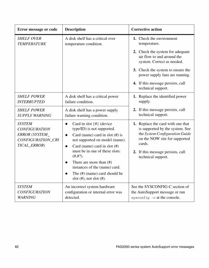
SHELF OVER TEMPERATURE
A disk shelf has a critical over temperature condition.
1. Check the environment temperature.
2. Check the system for adequate air flow to and around the system. Correct as needed.
3. Check the system to ensure the power supply fans are running.
4. If this message persists, call technical support.
SHELF POWER INTERRUPTED
A disk shelf has a critical power failure condition.
1. Replace the identified power supply.
2. If this message persists, call technical support.
SHELF POWER SUPPLY WARNING
A disk shelf has a power supply failure warning condition.
SYSTEM CONFIGURATION ERROR (SYSTEM_ CONFIGURATION_CRITICAL_ERROR)
◆ Card in slot {#} (device type/ID) is not supported.
◆ Card (name) card in slot (#) is not supported on model (name).
◆ Card (name) card in slot (#) must be in one of these slots: (#,#?).
◆ There are more than (#) instances of the (name) card.
◆ The (#) (name) card should be slot (#), not slot (#).
1. Replace the card with one that is supported by the system. See the System Configuration Guide on the NOW site for supported cards.
2. If this message persists, call technical support.
SYSTEM CONFIGURATION WARNING
An incorrect system hardware configuration or internal error was detected.
See the SYSCONFIG-C section of the AutoSupport message or run sysconfig -c at the console.
Error message or code Description Corrective action
82 FAS2000 series system AutoSupport error messages
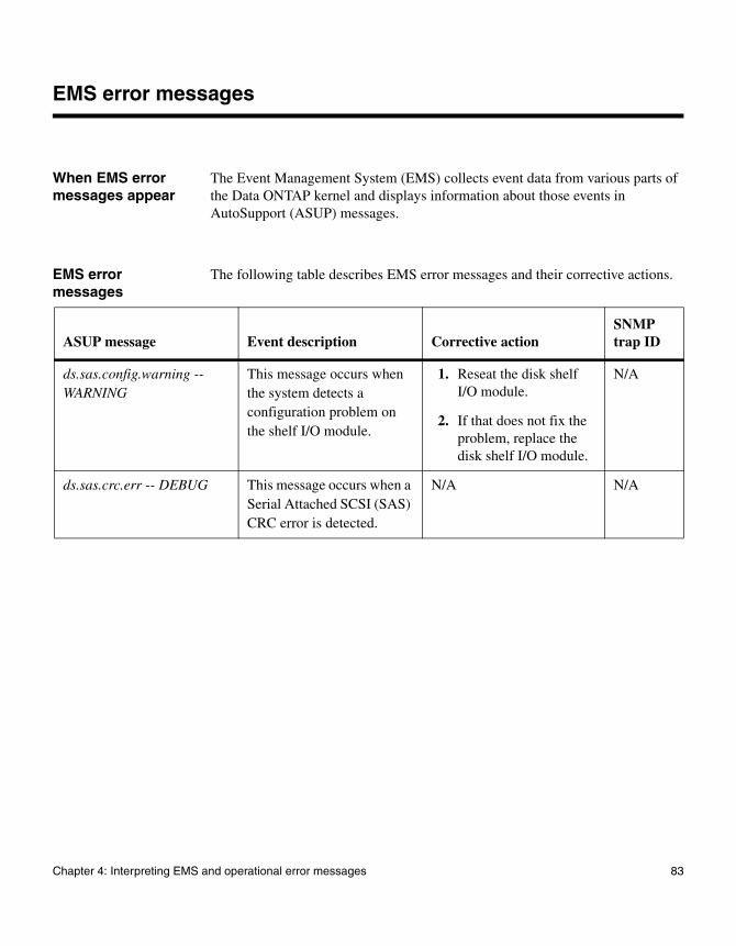
EMS error messages
When EMS error messages appear
The Event Management System (EMS) collects event data from various parts of the Data ONTAP kernel and displays information about those events in AutoSupport (ASUP) messages.
EMS error messages
The following table describes EMS error messages and their corrective actions.
ASUP message Event description Corrective actionSNMP trap ID
ds.sas.config.warning -- WARNING
This message occurs when the system detects a configuration problem on the shelf I/O module.
1. Reseat the disk shelf I/O module.
2. If that does not fix the problem, replace the disk shelf I/O module.
N/A
ds.sas.crc.err -- DEBUG This message occurs when a Serial Attached SCSI (SAS) CRC error is detected.
N/A N/A
Chapter 4: Interpreting EMS and operational error messages 83
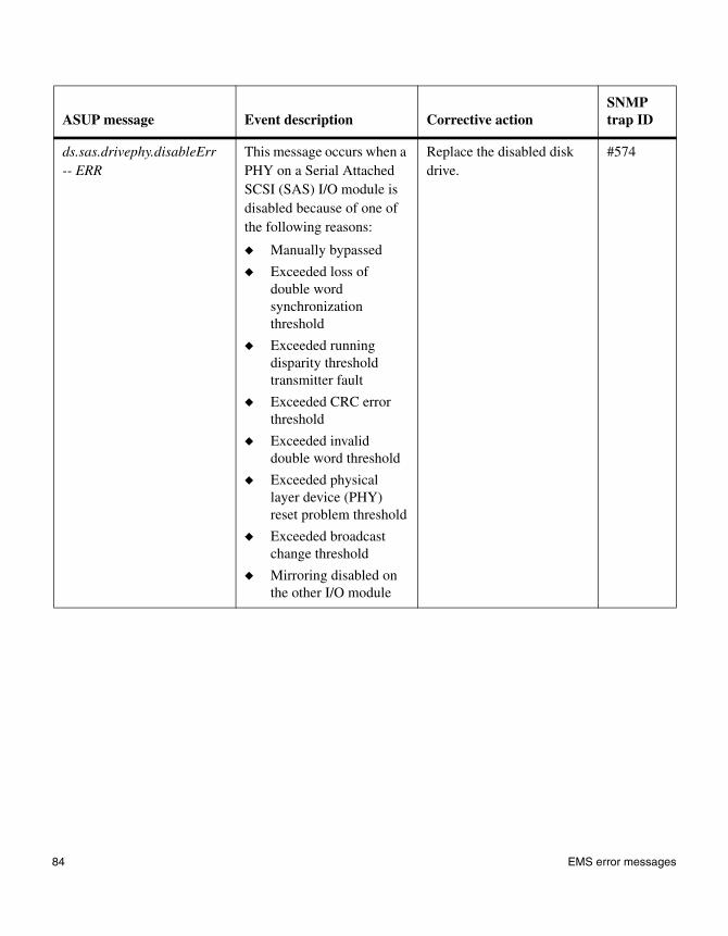
ds.sas.drivephy.disableErr -- ERR
This message occurs when a PHY on a Serial Attached SCSI (SAS) I/O module is disabled because of one of the following reasons:
◆ Manually bypassed
◆ Exceeded loss of double word synchronization threshold
◆ Exceeded running disparity threshold transmitter fault
◆ Exceeded CRC error threshold
◆ Exceeded invalid double word threshold
◆ Exceeded physical layer device (PHY) reset problem threshold
◆ Exceeded broadcast change threshold
◆ Mirroring disabled on the other I/O module
Replace the disabled disk drive.
#574
ASUP message Event description Corrective actionSNMP trap ID
84 EMS error messages
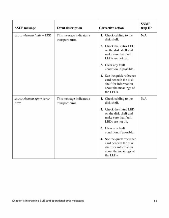
ds.sas.element.fault -- ERR This message indicates a transport error.
1. Check cabling to the disk shelf.
2. Check the status LED on the disk shelf and make sure that fault LEDs are not on.
3. Clear any fault condition, if possible.
4. See the quick reference card beneath the disk shelf for information about the meanings of the LEDs.
N/A
ds.sas.element.xport.error -- ERR
This message indicates a transport error.
1. Check cabling to the disk shelf.
2. Check the status LED on the disk shelf and make sure that fault LEDs are not on.
3. Clear any fault condition, if possible.
4. See the quick reference card beneath the disk shelf for information about the meanings of the LEDs.
N/A
ASUP message Event description Corrective actionSNMP trap ID
Chapter 4: Interpreting EMS and operational error messages 85

ds.sas.hostphy.disableErr -- ERR
This message occurs when a host physical layer device (PHY) on a Serial Attached SCSI (SAS) I/O module is disabled because of one of the following reasons:
◆ Manually bypassed
◆ Exceeded loss of double word synchronization threshold
◆ Exceeded running disparity threshold Transmitter fault
◆ Exceeded CRC error threshold
◆ Exceeded invalid double word threshold
◆ Exceeded PHY reset problem threshold
◆ Exceeded broadcast change threshold
◆ Mirroring disabled on the other I/O module
Replace the disk shelf module to which the host PHY belongs.
N/A
ds.sas.invalid.word -- DEBUG
This message occurs when a Serial Attached SCSI (SAS) word error is detected in a SAS primitive. These errors can be caused by the disk drive, the cable, the HBA, or the shelf I/O module.
The SAS specification allows for a certain bit error rate so that these errors can occur. There is nothing to be alarmed about if these individual errors show up occasionally.
N/A
ASUP message Event description Corrective actionSNMP trap ID
86 EMS error messages

ds.sas.loss.dword -- DEBUG
This message occurs when a Serial Attached SCSI (SAS) loss of double word synchronization error is detected in a SAS primitive.
N/A N/A
ds.sas.multPhys.disableErr -- ERR
This message occurs when physical layer devices (PHYs) are disabled on multiple disk drives in a Serial Attached SCSI (SAS) disk shelf.
1. Check whether the problems on the PHYs are valid.
2. If multiple physical layer devices PHYs are disabled at the same time, replace the disk shelf module.
N/A
ds.sas.phyRstProb -- DEBUG
This message occurs when a Serial Attached SCSI (SAS) physical layer device (PHY) reset error is detected in a SAS primitive.
N/A N/A
ds.sas.running.disparity -- DEBUG
This message occurs when a Serial Attached SCSI (SAS) running disparity error is detected in a SAS primitive. These errors are caused when the number of logical 1s and 0s are too much out of sync.
N/A N/A
ASUP message Event description Corrective actionSNMP trap ID
Chapter 4: Interpreting EMS and operational error messages 87

ds.sas.ses.disableErr -- NODE_ERROR
This message occurs when a virtual SCSI Enclosure Services (SES) physical layer device (PHY) on a Serial Attached SCSI (SAS) I/O module is disabled due to one of the following reasons:
◆ Manually bypassed
◆ Exceeded loss of double word synchronization threshold
◆ Exceeded running disparity threshold Transmitter fault
◆ Exceeded CRC error threshold
◆ Exceeded invalid double word threshold
◆ Exceeded PHY reset problem threshold
◆ Exceeded broadcast change threshold
Replace the shelf module to which the concerned SES PHY belongs.
N/A
ASUP message Event description Corrective actionSNMP trap ID
88 EMS error messages

ds.sas.xfer.element.fault -- ERR
This message indicates that an element had a fault during an I/O request. It might be because of a transient condition in link connectivity.
1. Check cabling to the shelf.
2. Check the status LED on the shelf, and make sure that fault LEDs are not on.
3. Clear any fault condition, if possible.
4. See the quick reference card beneath the shelf for information about the meanings of the LEDs.
N/A
ds.sas.xfer.export.error -- ERR
This message indicates a transport error during an I/O request. It might be due to a transient condition in link activity.
1. Check cabling to the shelf.
2. Check the status LED on the shelf, and make sure that the fault LEDs are not on.
3. Clear any fault condition, if possible.
4. See the quick reference card beneath the shelf for information about the meanings of the LEDs.
N/A
ASUP message Event description Corrective actionSNMP trap ID
Chapter 4: Interpreting EMS and operational error messages 89

ds.sas.xfer.not.sent -- ERR This message indicates that an I/O transfer could not be sent. It might be because of a transient condition in link connectivity.
1. Check cabling to the shelf.
2. Check the status LED on the shelf, and make sure that fault LEDs are not on.
3. Clear any fault condition, if possible.
4. See the quick reference card beneath the shelf for information about the meanings of the LEDs.
N/A
ds.sas.xfer.unknown.error -- ERR
This message indicates that an unknown error occurred during an I/O request.
N/A N/A
sas.adapter.bad -- ALERT This message occurs when the Serial Attached SCSI (SAS) adapter fails to initialize.
1. Reseat the adapter.
2. If reseating the adapter failed to help, replace the adapter.
N/A
sas.adapter.bootarg.option -- INFO
The Serial Attached SCSI (SAS) adapter driver is setting an option based on the setting of a bootarg/environment variable.
None. N/A
sas.adapter.debug -- INFO This message occurs during the Serial Attached SCSI (SAS) adapter driver debug event.
None. N/A
ASUP message Event description Corrective actionSNMP trap ID
90 EMS error messages
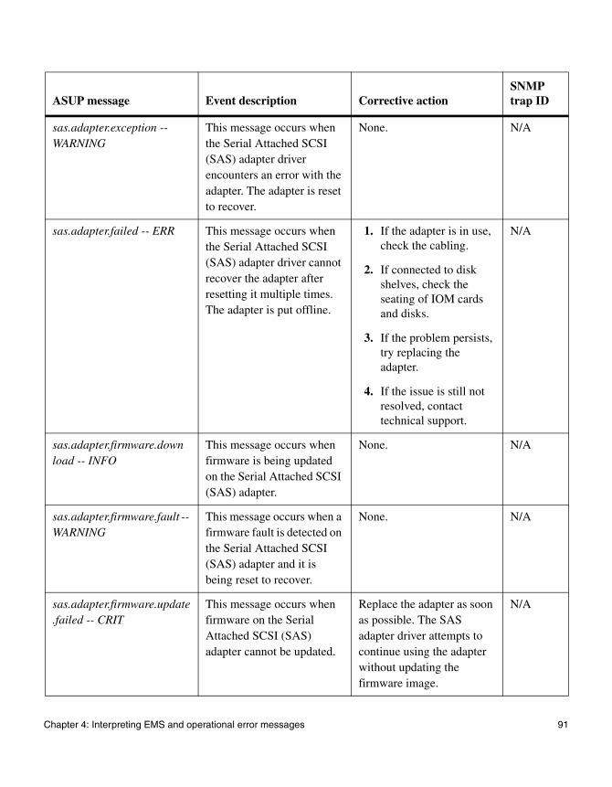
sas.adapter.exception -- WARNING
This message occurs when the Serial Attached SCSI (SAS) adapter driver encounters an error with the adapter. The adapter is reset to recover.
None. N/A
sas.adapter.failed -- ERR This message occurs when the Serial Attached SCSI (SAS) adapter driver cannot recover the adapter after resetting it multiple times. The adapter is put offline.
1. If the adapter is in use, check the cabling.
2. If connected to disk shelves, check the seating of IOM cards and disks.
3. If the problem persists, try replacing the adapter.
4. If the issue is still not resolved, contact technical support.
N/A
sas.adapter.firmware.download -- INFO
This message occurs when firmware is being updated on the Serial Attached SCSI (SAS) adapter.
None. N/A
sas.adapter.firmware.fault -- WARNING
This message occurs when a firmware fault is detected on the Serial Attached SCSI (SAS) adapter and it is being reset to recover.
None. N/A
sas.adapter.firmware.update.failed -- CRIT
This message occurs when firmware on the Serial Attached SCSI (SAS) adapter cannot be updated.
Replace the adapter as soon as possible. The SAS adapter driver attempts to continue using the adapter without updating the firmware image.
N/A
ASUP message Event description Corrective actionSNMP trap ID
Chapter 4: Interpreting EMS and operational error messages 91

sas.adapter.not.ready -- ERR
This message occurs when the Serial Attached SCSI (SAS) adapter does not become ready after being reset.
The SAS adapter driver automatically attempts to recover from this error. If the error keeps occurring, the adapter might need to be replaced.
N/A
sas.adapter.offline -- INFO This message indicates the name of the associated Serial Attached SCSI (SAS) host bus adapter (HBA).
None. N/A
sas.adapter.offlining -- INFO
This message occurs when the Serial Attached SCSI (SAS) adapter is going offline after all outstanding I/O requests have finished.
None. N/A
sas.adapter.online -- INFO This message indicates that the Serial Attached SCSI (SAS) adapter is now online.
None. N/A
sas.adapter.online.failed -- ERR
This message indicates the name of the associated Serial Attached SCSI (SAS) host bus adapter (HBA).
1. If the HBA is in use, check the cabling.
2. If the HBA is connected to disk shelves, check the seating of IOM cards.
N/A
sas.adapter.onlining -- INFO
This message indicates that the Serial Attached SCSI (SAS) adapter is in the process of going online.
None. N/A
ASUP message Event description Corrective actionSNMP trap ID
92 EMS error messages
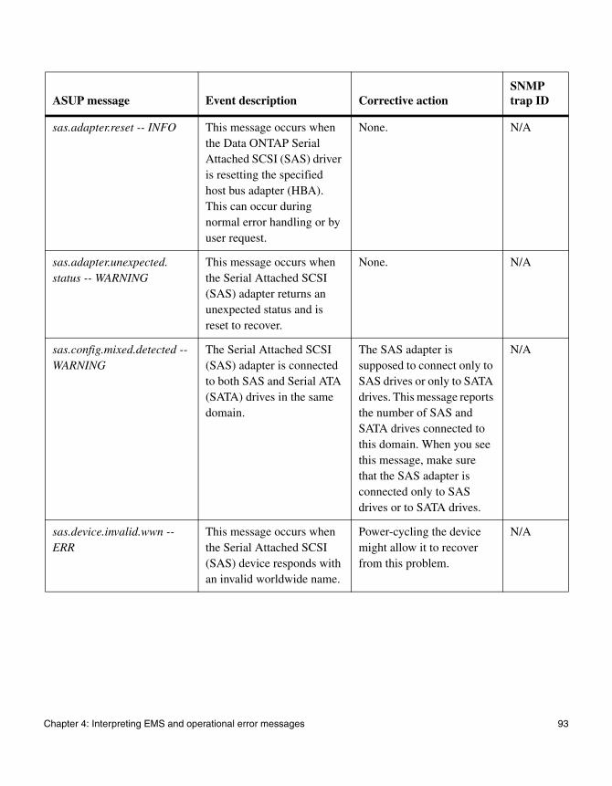
sas.adapter.reset -- INFO This message occurs when the Data ONTAP Serial Attached SCSI (SAS) driver is resetting the specified host bus adapter (HBA). This can occur during normal error handling or by user request.
None. N/A
sas.adapter.unexpected.status -- WARNING
This message occurs when the Serial Attached SCSI (SAS) adapter returns an unexpected status and is reset to recover.
None. N/A
sas.config.mixed.detected -- WARNING
The Serial Attached SCSI (SAS) adapter is connected to both SAS and Serial ATA (SATA) drives in the same domain.
The SAS adapter is supposed to connect only to SAS drives or only to SATA drives. This message reports the number of SAS and SATA drives connected to this domain. When you see this message, make sure that the SAS adapter is connected only to SAS drives or to SATA drives.
N/A
sas.device.invalid.wwn -- ERR
This message occurs when the Serial Attached SCSI (SAS) device responds with an invalid worldwide name.
Power-cycling the device might allow it to recover from this problem.
N/A
ASUP message Event description Corrective actionSNMP trap ID
Chapter 4: Interpreting EMS and operational error messages 93
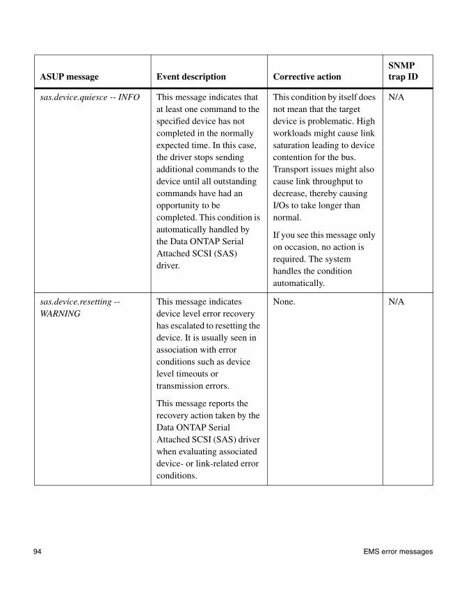
sas.device.quiesce -- INFO This message indicates that at least one command to the specified device has not completed in the normally expected time. In this case, the driver stops sending additional commands to the device until all outstanding commands have had an opportunity to be completed. This condition is automatically handled by the Data ONTAP Serial Attached SCSI (SAS) driver.
This condition by itself does not mean that the target device is problematic. High workloads might cause link saturation leading to device contention for the bus. Transport issues might also cause link throughput to decrease, thereby causing I/Os to take longer than normal.
If you see this message only on occasion, no action is required. The system handles the condition automatically.
N/A
sas.device.resetting -- WARNING
This message indicates device level error recovery has escalated to resetting the device. It is usually seen in association with error conditions such as device level timeouts or transmission errors.
This message reports the recovery action taken by the Data ONTAP Serial Attached SCSI (SAS) driver when evaluating associated device- or link-related error conditions.
None. N/A
ASUP message Event description Corrective actionSNMP trap ID
94 EMS error messages

sas.device.timeout -- ERR This message occurs when not all outstanding commands to the specified device were completed within the allotted time. As part of the standard error handling sequence managed by the Data ONTAP Serial Attached SCSI (SAS) driver, all commands to the device are aborted and reissued.
Device level timeouts are a common indication of a SAS link stability problem. In some cases, the link is operating normally and the specified device is having trouble processing I/O requests in a timely manner. In such cases, the specified device should be evaluated for possible replacement.
Quite often the problem results from the partial failure of a component involved in the SAS transport. Common things to check include the following:
◆ Complete seating of drive carriers in enclosure bays
◆ Properly secured cable connections
◆ IOM seating
◆ Crimped or otherwise damaged cables
N/A
sas.initialization.failed -- ERR
This message occurs when the Serial Attached SCSI (SAS) adapter fails to initialize the link and appears to be unattached or disconnected.
1. If the adapter is in use, check the cabling.
2. If the adapter is connected to disk shelves, check the seating of IOM cards.
N/A
ASUP message Event description Corrective actionSNMP trap ID
Chapter 4: Interpreting EMS and operational error messages 95

sas.link.error -- ERR This message occurs when the Serial Attached SCSI (SAS) adapter cannot recover the link and is going offline.
1. If the adapter is in use, check the cabling.
2. If the adapter is connected to disk shelves, check the seating of IOM cards and disks.
3. If this does not resolve the issue, contact technical support.
N/A
sasmon.adapter.phy.event -- DEBUG
This message occurs when a serial attached SCSI (SAS) transceiver (PHY) attached to a SAS host bus adapter (HBA) experiences a transient error. These errors are observed on a received double word (dword) or when resetting a PHY.
Types of these errors are disparity errors, invalid dword errors, PHY reset problem errors, loss of dword synchronization errors, and PHY change events. The SAS specification allows for a certain bit error rate so that these errors can occur under normal operating conditions.
There is no cause for concern if these individual errors show up occasionally.
None. N/A
ASUP message Event description Corrective actionSNMP trap ID
96 EMS error messages

sasmon.adapter.phy.disable -- ERR
This message occurs when a serial attached SCSI (SAS) transceiver (PHY) attached to a SAS host bus adapter (HBA) is disabled due to one of the following reasons:
◆ Exceeded loss of double word synchronization error threshold
◆ Exceeded running disparity error threshold
◆ Exceeded invalid double word error threshold
◆ Exceeded PHY reset problem threshold
◆ Exceeded broadcast change threshold
1. If the adapter is in use, check the cabling.
2. If the adapter is connected to the disk shelves, check the seating of the IOM cards.
3. If that does not fix the problem, contact technical support.
N/A
sasmon.disable.module -- INFO
This message occurs when the Data ONTAP module responsible for monitoring the serial attached SCSI (SAS) domain’s transient errors is disabled due to the environment variable disable-sasmon? being set to true.
Set the environment variable disable-sasmon? to false to enable this monitor module.
N/A
ASUP message Event description Corrective actionSNMP trap ID
Chapter 4: Interpreting EMS and operational error messages 97

Environmental EMS error messages
When environmental EMS error messages appear
Environmental EMS messages appear on the LCD display and in AutoSupport (ASUP) messages if your system encounters extremes in its operational environment.
Environmental EMS error messages
The following table describes the environmental EMS messages and their corrective actions.
LCD display
ASUP message and LED behavior Event description Corrective action
SNMP trap ID
Power supply degraded
Chassis Power degraded: PS#
FRU LED: Amber
This message occurs when there is a problem with one of the power supplies.
1. Check that the power supply is seated properly in its bay and that all power cords are connected.
2. Power-cycle your system and run diagnostics on the identified power supply.
3. If the problem persists, replace the identified power supply.
#392: Chassis power supply is degraded
98 Environmental EMS error messages

Power supply degraded
Chassis Power Supply: PS# removed system will shutdown in 2 minutes
FRU LED: Amber
This message occurs when the power supply unit is removed from the system. The system will shut down unless the power supply is replaced.
Your action depends on whether the power supply is present.
◆ If the power supply is not inserted, insert it.
◆ If the power supply is inserted, power-cycle your system and run diagnostics on the identified power supply. If the problem persists, replace the identified power supply.
#501: Chassis power supply is degraded
Power supply degraded
Chassis Power Shutdown: Chassis Power Supply Fail: PS#
This message occurs when the system is in a warning state. The system shuts down immediately.
Your action depends on whether the power supply is present.
◆ If the power supply is not inserted, insert it.
◆ If the power supply is inserted, power-cycle your system and run diagnostics on the identified power supply. If the problem persists, replace the identified power supply.
#392: Chassis power supply is degraded
LCD display
ASUP message and LED behavior Event description Corrective action
SNMP trap ID
Chapter 4: Interpreting EMS and operational error messages 99

Power supply degraded
Chassis Power Fail: PS#
This message occurs when the power supply fails.
Your action depends on whether the power supply is present.
◆ If the power supply is not inserted, insert it.
◆ If the power supply is inserted, power-cycle your system and run diagnostics on the identified power supply. If the problem persists, replace the identified power supply.
#6: Chassis power is degraded
Power supply degraded
Multiple fan failure The message occurs when multiple fans fail. The system shuts down immediately.
Your action depends on whether the power supply is present.
◆ If the power supply is not inserted, insert it.
◆ If the power supply is inserted, power-cycle your system and run diagnostics on the identified power supply. If the problem persists, replace the identified power supply.
#6: Chassis power is degraded
LCD display
ASUP message and LED behavior Event description Corrective action
SNMP trap ID
100 Environmental EMS error messages
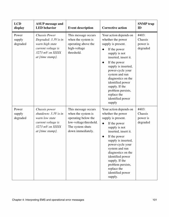
Power supply degraded
Chassis Power Degraded: 3.3V is in warn high state current voltage is 3273 mV on XXXX at [time stamp].
This message occurs when the system is operating above the high-voltage threshold.
Your action depends on whether the power supply is present.
◆ If the power supply is not inserted, insert it.
◆ If the power supply is inserted, power-cycle your system and run diagnostics on the identified power supply. If the problem persists, replace the identified power supply
#403: Chassis power is degraded
Power supply degraded
Chassis power shutdown: 3.3V is in warn low state current voltage is 3273 mV on XXXX at [time stamp].
This message occurs when the system is operating below the low-voltage threshold. The system shuts down immediately.
Your action depends on whether the power supply is present.
◆ If the power supply is not inserted, insert it.
◆ If the power supply is inserted, power-cycle your system and run diagnostics on the identified power supply. If the problem persists, replace the identified power supply.
#403: Chassis power is degraded
LCD display
ASUP message and LED behavior Event description Corrective action
SNMP trap ID
Chapter 4: Interpreting EMS and operational error messages 101
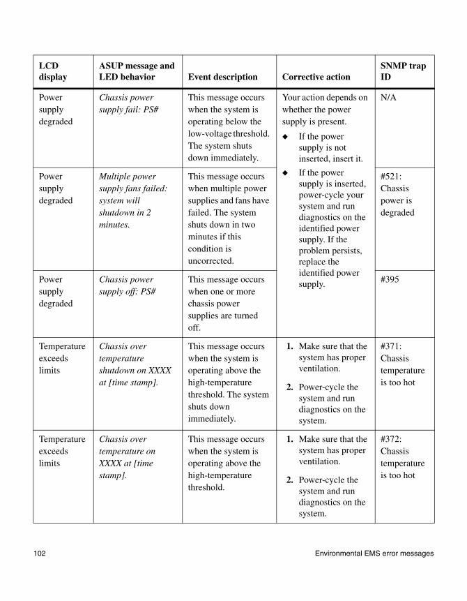
Power supply degraded
Chassis power supply fail: PS#
This message occurs when the system is operating below the low-voltage threshold. The system shuts down immediately.
Your action depends on whether the power supply is present.
◆ If the power supply is not inserted, insert it.
◆ If the power supply is inserted, power-cycle your system and run diagnostics on the identified power supply. If the problem persists, replace the identified power supply.
N/A
Power supply degraded
Multiple power supply fans failed: system will shutdown in 2 minutes.
This message occurs when multiple power supplies and fans have failed. The system shuts down in two minutes if this condition is uncorrected.
#521: Chassis power is degraded
Power supply degraded
Chassis power supply off: PS#
This message occurs when one or more chassis power supplies are turned off.
#395
Temperature exceedslimits
Chassis over temperature shutdown on XXXX at [time stamp].
This message occurs when the system is operating above the high-temperature threshold. The system shuts down immediately.
1. Make sure that the system has proper ventilation.
2. Power-cycle the system and run diagnostics on the system.
#371: Chassis temperature is too hot
Temperature exceedslimits
Chassis over temperature on XXXX at [time stamp].
This message occurs when the system is operating above the high-temperature threshold.
1. Make sure that the system has proper ventilation.
2. Power-cycle the system and run diagnostics on the system.
#372: Chassis temperature is too hot
LCD display
ASUP message and LED behavior Event description Corrective action
SNMP trap ID
102 Environmental EMS error messages
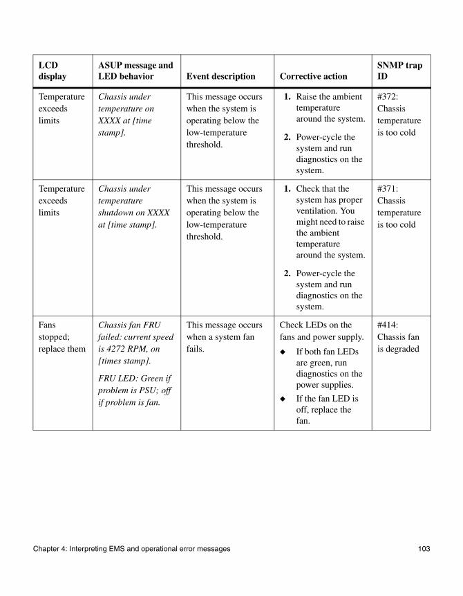
Temperature exceedslimits
Chassis under temperature on XXXX at [time stamp].
This message occurs when the system is operating below the low-temperature threshold.
1. Raise the ambient temperature around the system.
2. Power-cycle the system and run diagnostics on the system.
#372: Chassis temperature is too cold
Temperature exceedslimits
Chassis under temperature shutdown on XXXX at [time stamp].
This message occurs when the system is operating below the low-temperature threshold.
1. Check that the system has proper ventilation. You might need to raise the ambient temperature around the system.
2. Power-cycle the system and run diagnostics on the system.
#371: Chassis temperature is too cold
Fans stopped; replace them
Chassis fan FRU failed: current speed is 4272 RPM, on [times stamp].
FRU LED: Green if problem is PSU; off if problem is fan.
This message occurs when a system fan fails.
Check LEDs on the fans and power supply.
◆ If both fan LEDs are green, run diagnostics on the power supplies.
◆ If the fan LED is off, replace the fan.
#414: Chassis fan is degraded
LCD display
ASUP message and LED behavior Event description Corrective action
SNMP trap ID
Chapter 4: Interpreting EMS and operational error messages 103
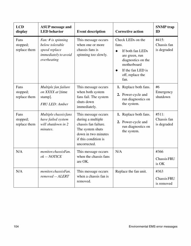
Fans stopped; replace them
Fan: # is spinning below tolerable speed replace immediately to avoid overheating
This message occurs when one or more chassis fans is spinning too slowly.
Check LEDs on the fans.
◆ If both fan LEDs are green, run diagnostics on the motherboard
◆ If the fan LED is off, replace the fan.
#415: Chassis fan is degraded
Fans stopped; replace them
Multiple fan failure on XXXX at [time stamp].
FRU LED: Amber
This message occurs when both system fans fail. The system shuts down immediately.
1. Replace both fans.
2. Power-cycle and run diagnostics on the system.
#6 Emergency shutdown
Fans stopped; replace them
Multiple chassis fans have failed system will shutdown in 2 minutes.
This message occurs during a multiple chassis fan failure. The system shuts down in two minutes if this condition is uncorrected.
1. Replace both fans.
2. Power-cycle and run diagnostics on the system.
#511: Chassis fan is degraded
N/A monitor.chassisFan.ok -- NOTICE
This message occurs when the chassis fans are OK.
N/A #366
Chassis FRU is OK
N/A monitor.chassisFan.removed -- ALERT
This message occurs when a chassis fan is removed.
Replace the fan unit. #363
Chassis FRU is removed
LCD display
ASUP message and LED behavior Event description Corrective action
SNMP trap ID
104 Environmental EMS error messages
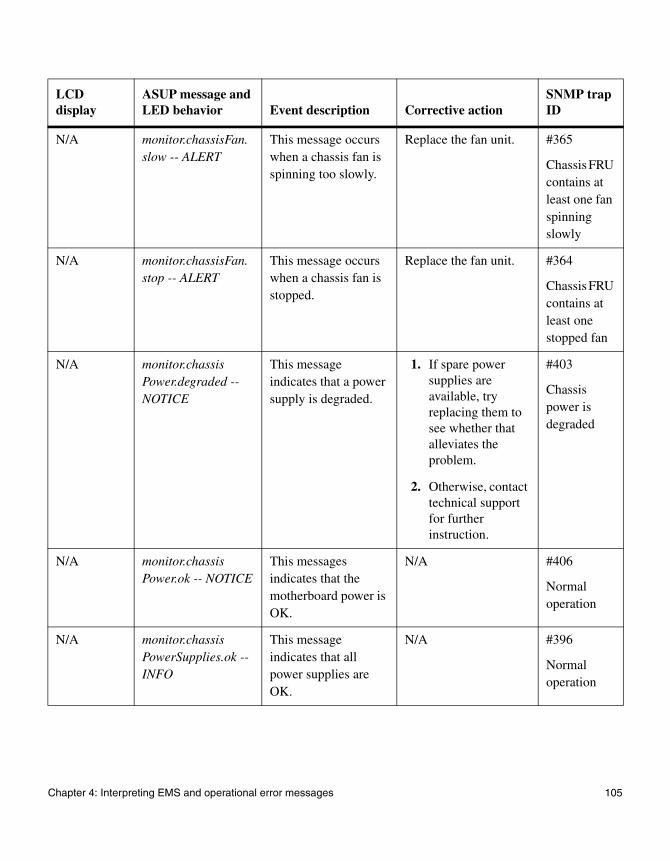
N/A monitor.chassisFan.slow -- ALERT
This message occurs when a chassis fan is spinning too slowly.
Replace the fan unit. #365
Chassis FRU contains at least one fan spinning slowly
N/A monitor.chassisFan.stop -- ALERT
This message occurs when a chassis fan is stopped.
Replace the fan unit. #364
Chassis FRU contains at least one stopped fan
N/A monitor.chassisPower.degraded -- NOTICE
This message indicates that a power supply is degraded.
1. If spare power supplies are available, try replacing them to see whether that alleviates the problem.
2. Otherwise, contact technical support for further instruction.
#403
Chassis power is degraded
N/A monitor.chassisPower.ok -- NOTICE
This messages indicates that the motherboard power is OK.
N/A #406
Normal operation
N/A monitor.chassisPowerSupplies.ok -- INFO
This message indicates that all power supplies are OK.
N/A #396
Normal operation
LCD display
ASUP message and LED behavior Event description Corrective action
SNMP trap ID
Chapter 4: Interpreting EMS and operational error messages 105

N/A monitor.chassisPowerSupply.degraded -- NOTICE
This message indicates that a power supply is degraded.
A replacement power supply might be required. Contact technical support for further instruction.
#392
Chassis power supply is degraded
N/A monitor.chassisPowerSupply.notPresent -- NOTICE
This message indicates that a power supply is not present.
Replace the power supply.
#394
Power supply not present
N/A monitor.chassisPowerSupply.off -- NOTICE
This message indicates that a power supply is turned off.
Turn on the power supply.
#395
Power supply not present
N/A monitor.chassisTemperature.cool -- ALERT
This message occurs when the chassis temperature is too cool.
Raise the temperature around the storage system.
#372
Chassis temperature is too cool
N/A monitor.chassisTemperature.ok -- NOTICE
This message occurs when the chassis temperature is normal.
N/A #376
Normal operation
N/A monitor.chassisTemperature.warm -- ALERT
This message occurs when the chassis temperature is too warm.
Check to see whether air conditioning units are needed, or whether they are functioning properly.
#372
Chassis temperature is too warm
LCD display
ASUP message and LED behavior Event description Corrective action
SNMP trap ID
106 Environmental EMS error messages
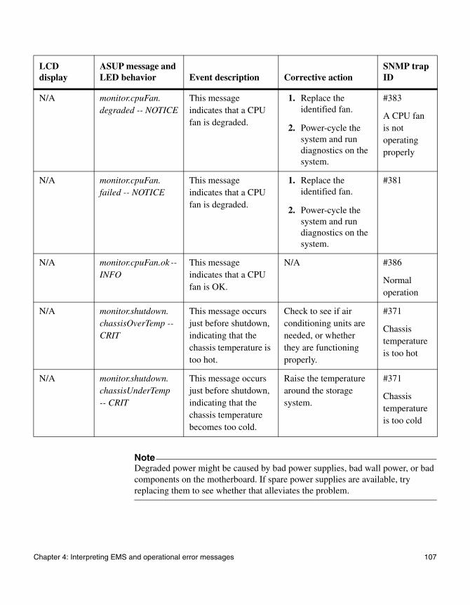
NoteDegraded power might be caused by bad power supplies, bad wall power, or bad components on the motherboard. If spare power supplies are available, try replacing them to see whether that alleviates the problem.
N/A monitor.cpuFan.degraded -- NOTICE
This message indicates that a CPU fan is degraded.
1. Replace the identified fan.
2. Power-cycle the system and run diagnostics on the system.
#383
A CPU fan is not operating properly
N/A monitor.cpuFan.failed -- NOTICE
This message indicates that a CPU fan is degraded.
1. Replace the identified fan.
2. Power-cycle the system and run diagnostics on the system.
#381
N/A monitor.cpuFan.ok -- INFO
This message indicates that a CPU fan is OK.
N/A #386
Normal operation
N/A monitor.shutdown.chassisOverTemp -- CRIT
This message occurs just before shutdown, indicating that the chassis temperature is too hot.
Check to see if air conditioning units are needed, or whether they are functioning properly.
#371
Chassis temperature is too hot
N/A monitor.shutdown.chassisUnderTemp -- CRIT
This message occurs just before shutdown, indicating that the chassis temperature becomes too cold.
Raise the temperature around the storage system.
#371
Chassis temperature is too cold
LCD display
ASUP message and LED behavior Event description Corrective action
SNMP trap ID
Chapter 4: Interpreting EMS and operational error messages 107
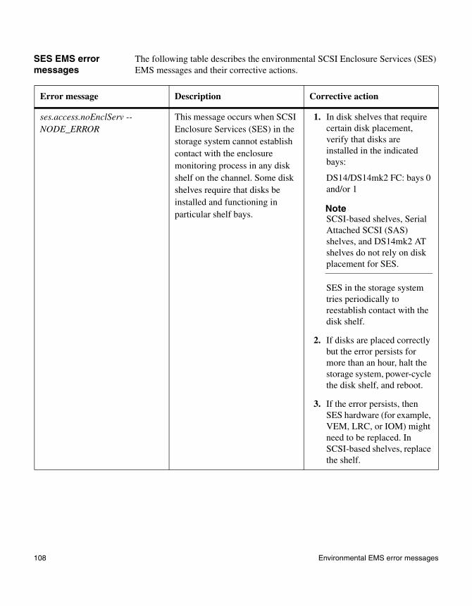
SES EMS error messages
The following table describes the environmental SCSI Enclosure Services (SES) EMS messages and their corrective actions.
Error message Description Corrective action
ses.access.noEnclServ -- NODE_ERROR
This message occurs when SCSI Enclosure Services (SES) in the storage system cannot establish contact with the enclosure monitoring process in any disk shelf on the channel. Some disk shelves require that disks be installed and functioning in particular shelf bays.
1. In disk shelves that require certain disk placement, verify that disks are installed in the indicated bays:
DS14/DS14mk2 FC: bays 0 and/or 1
NoteSCSI-based shelves, Serial Attached SCSI (SAS) shelves, and DS14mk2 AT shelves do not rely on disk placement for SES.
SES in the storage system tries periodically to reestablish contact with the disk shelf.
2. If disks are placed correctly but the error persists for more than an hour, halt the storage system, power-cycle the disk shelf, and reboot.
3. If the error persists, then SES hardware (for example, VEM, LRC, or IOM) might need to be replaced. In SCSI-based shelves, replace the shelf.
108 Environmental EMS error messages

ses.access.noMoreValidPaths -- NODE_ERROR
This message occurs when SCSI Enclosure Services (SES) in the storage system loses access to the enclosure monitoring process in the disk shelf. Some disk shelves require that disks be installed and functioning in particular shelf bays.
1. In disk shelves that require certain disk placement, verify that disks are installed in the indicated bays:
DS14/DS14mk2 FC: bays 0 and/or 1
NoteSCSI-based shelves, Serial Attached SCSI (SAS) shelves, and DS14mk2 AT shelves do not rely on disk placement for SES.
SES in the storage system tries periodically to reestablish contact with the disk shelf.
2. If disks are placed correctly, but the error persists for more than an hour, halt the storage system, power-cycle the disk shelf, and reboot.
3. If the error persists, then SES hardware (for example, VEM, LRC, or IOM) might need to be replaced. In SCSI-based shelves, replace the shelf.
Error message Description Corrective action
Chapter 4: Interpreting EMS and operational error messages 109
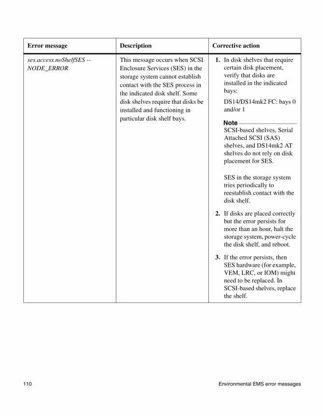
ses.access.noShelfSES -- NODE_ERROR
This message occurs when SCSI Enclosure Services (SES) in the storage system cannot establish contact with the SES process in the indicated disk shelf. Some disk shelves require that disks be installed and functioning in particular disk shelf bays.
1. In disk shelves that require certain disk placement, verify that disks are installed in the indicated bays:
DS14/DS14mk2 FC: bays 0 and/or 1
NoteSCSI-based shelves, Serial Attached SCSI (SAS) shelves, and DS14mk2 AT shelves do not rely on disk placement for SES.
SES in the storage system tries periodically to reestablish contact with the disk shelf.
2. If disks are placed correctly but the error persists for more than an hour, halt the storage system, power-cycle the disk shelf, and reboot.
3. If the error persists, then SES hardware (for example, VEM, LRC, or IOM) might need to be replaced. In SCSI-based shelves, replace the shelf.
Error message Description Corrective action
110 Environmental EMS error messages
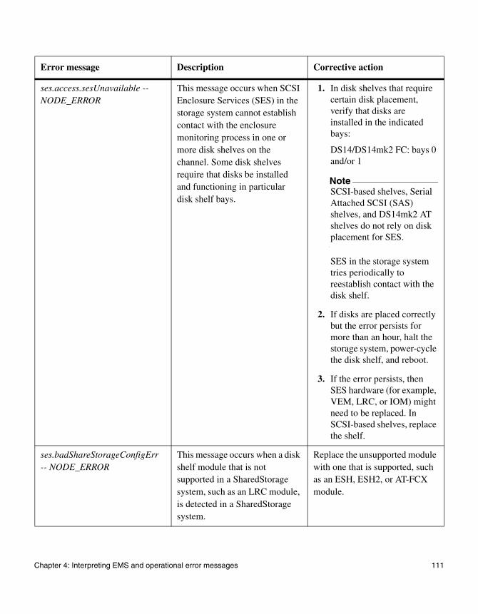
ses.access.sesUnavailable -- NODE_ERROR
This message occurs when SCSI Enclosure Services (SES) in the storage system cannot establish contact with the enclosure monitoring process in one or more disk shelves on the channel. Some disk shelves require that disks be installed and functioning in particular disk shelf bays.
1. In disk shelves that require certain disk placement, verify that disks are installed in the indicated bays:
DS14/DS14mk2 FC: bays 0 and/or 1
NoteSCSI-based shelves, Serial Attached SCSI (SAS) shelves, and DS14mk2 AT shelves do not rely on disk placement for SES.
SES in the storage system tries periodically to reestablish contact with the disk shelf.
2. If disks are placed correctly but the error persists for more than an hour, halt the storage system, power-cycle the disk shelf, and reboot.
3. If the error persists, then SES hardware (for example, VEM, LRC, or IOM) might need to be replaced. In SCSI-based shelves, replace the shelf.
ses.badShareStorageConfigErr -- NODE_ERROR
This message occurs when a disk shelf module that is not supported in a SharedStorage system, such as an LRC module, is detected in a SharedStorage system.
Replace the unsupported module with one that is supported, such as an ESH, ESH2, or AT-FCX module.
Error message Description Corrective action
Chapter 4: Interpreting EMS and operational error messages 111

ses.bridge.fw.getFailWarn -- WARNING
This message occurs when the bridge firmware revision cannot be obtained.
Check the connection to the bank of Maxtor drives.
ses.bridge.fw.mmErr -- SVC_ERROR
This message occurs when the bridge firmware revision is inconsistent.
Check the firmware revision number and make sure that they are consistent. You might have to update the firmware.
ses.channel.rescanInitiated -- INFO
This message identifies the name of the adapter port or switch port being rescanned; for example, “7a” or “myswitch:5”.
None.
ses.config.drivePopError -- WARNING
This message occurs when the channel has more disk drives on it than are allowed.
Systems using synchronous mirroring allow more disk drives per channel than other systems.
Your action depends on whether you intend to use synchronous mirroring.
◆ If you intend to use synchronous mirroring, make sure that the license is installed.
◆ If you do not intend to use synchronous mirroring, reduce the number of disk drives on the channel to no more than the maximum allowed.
ses.config.IllegalEsh270 -- NODE_ERROR
This message occurs when Data ONTAP detects one or more ESH disk shelf modules in a disk shelf that is attached to a FAS270. This is not a supported configuration.
Replace the ESH modules with ESH2 modules.
Error message Description Corrective action
112 Environmental EMS error messages
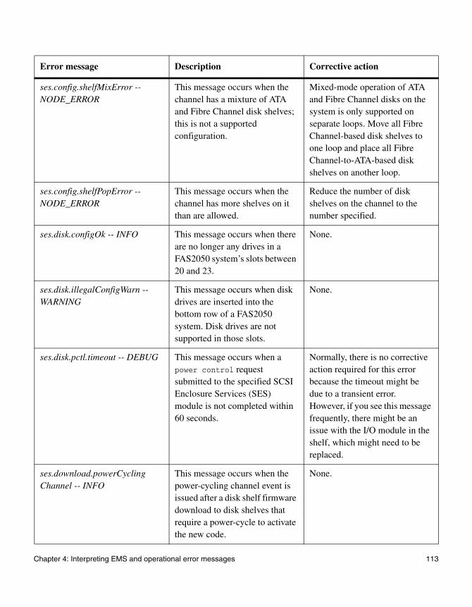
ses.config.shelfMixError -- NODE_ERROR
This message occurs when the channel has a mixture of ATA and Fibre Channel disk shelves; this is not a supported configuration.
Mixed-mode operation of ATA and Fibre Channel disks on the system is only supported on separate loops. Move all Fibre Channel-based disk shelves to one loop and place all Fibre Channel-to-ATA-based disk shelves on another loop.
ses.config.shelfPopError -- NODE_ERROR
This message occurs when the channel has more shelves on it than are allowed.
Reduce the number of disk shelves on the channel to the number specified.
ses.disk.configOk -- INFO This message occurs when there are no longer any drives in a FAS2050 system’s slots between 20 and 23.
None.
ses.disk.illegalConfigWarn -- WARNING
This message occurs when disk drives are inserted into the bottom row of a FAS2050 system. Disk drives are not supported in those slots.
None.
ses.disk.pctl.timeout -- DEBUG This message occurs when a power control request submitted to the specified SCSI Enclosure Services (SES) module is not completed within 60 seconds.
Normally, there is no corrective action required for this error because the timeout might be due to a transient error. However, if you see this message frequently, there might be an issue with the I/O module in the shelf, which might need to be replaced.
ses.download.powerCyclingChannel -- INFO
This message occurs when the power-cycling channel event is issued after a disk shelf firmware download to disk shelves that require a power-cycle to activate the new code.
None.
Error message Description Corrective action
Chapter 4: Interpreting EMS and operational error messages 113
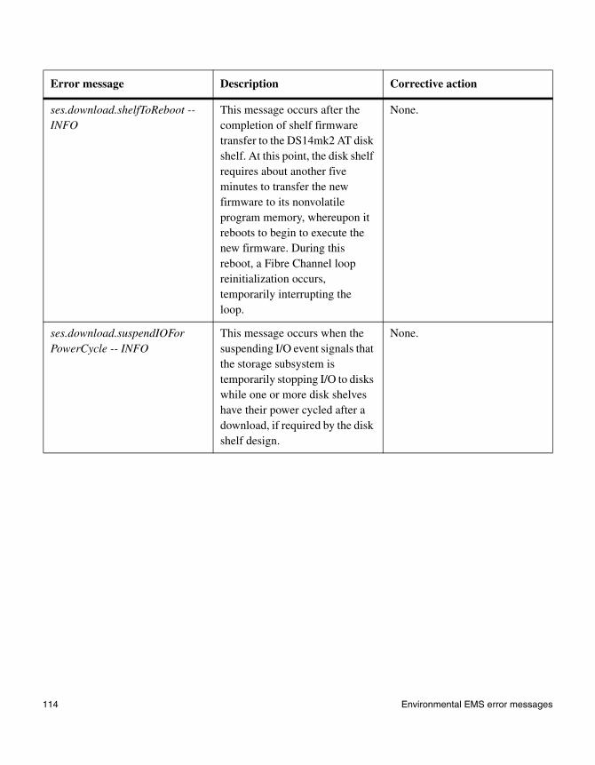
ses.download.shelfToReboot -- INFO
This message occurs after the completion of shelf firmware transfer to the DS14mk2 AT disk shelf. At this point, the disk shelf requires about another five minutes to transfer the new firmware to its nonvolatile program memory, whereupon it reboots to begin to execute the new firmware. During this reboot, a Fibre Channel loop reinitialization occurs, temporarily interrupting the loop.
None.
ses.download.suspendIOForPowerCycle -- INFO
This message occurs when the suspending I/O event signals that the storage subsystem is temporarily stopping I/O to disks while one or more disk shelves have their power cycled after a download, if required by the disk shelf design.
None.
Error message Description Corrective action
114 Environmental EMS error messages

ses.drive.PossShelfAddr -- WARNING
This message occurs in conjunction with the message ses.drive.shelfAddr.mm when there are devices that have apparently taken a wrong address; the adapter shows device addresses that SCSI Enclosure Services (SES) indicates should not exist, and vice versa.
This error is not a fatal condition. It means that SES cannot perform certain operations on the affected disk drives, such as setting failure LEDs, because it is not certain which disk shelf the affected disk drive is in.
1. If the problem is throughout the disk shelf, replace the disk shelf.
2. If the error is only one disk drive per disk shelf, the drive might have taken an incorrect address at power-on.
3. Arrange to make this disk drive a spare, and then reseat it to cause it to take its address again.
4. If the problem persists, insert a different spare disk drive into the slot. If the error then clears, replace the original disk drive.
5. If the problem persists, there is a hardware problem with the individual disk bay. Replace the disk shelf.
Error message Description Corrective action
Chapter 4: Interpreting EMS and operational error messages 115

ses.drive.shelfAddr.mm -- NODE_ERROR
This message occurs when there is a mismatch between the position of the drives detected by the disk shelf and the address of the drives detected by the Fibre Channel loop or SCSI bus.
This error indicates that a disk drive took an address other than what the disk shelf should have provided, or that SCSI Enclosure Services (SES) in a disk shelf cannot be contacted for address information, or that a disk drive unexpectedly does not participate in device discovery on the loop or bus.
If the message EMS_ses_drive_possShelfAddr
subsequently appears, follow the corrective actions in that message.
In this condition, the SES process in the system might be unable to perform certain operations on the disk, such as setting failure LEDs or detecting disk swaps.
1. If this occurs to multiple disk drives on the same loop, check the I/O modules at the back of the disk shelves on that loop for errors.
2. In disk shelves that require certain disk placement, verify that disks are installed in the indicated bays:
DS14/DS14mk2: bays 0 and/or 1
NoteSCSI-based disk shelves and DS14mk2 AT disk shelves do not rely on disk placement for SES.
Error message Description Corrective action
116 Environmental EMS error messages
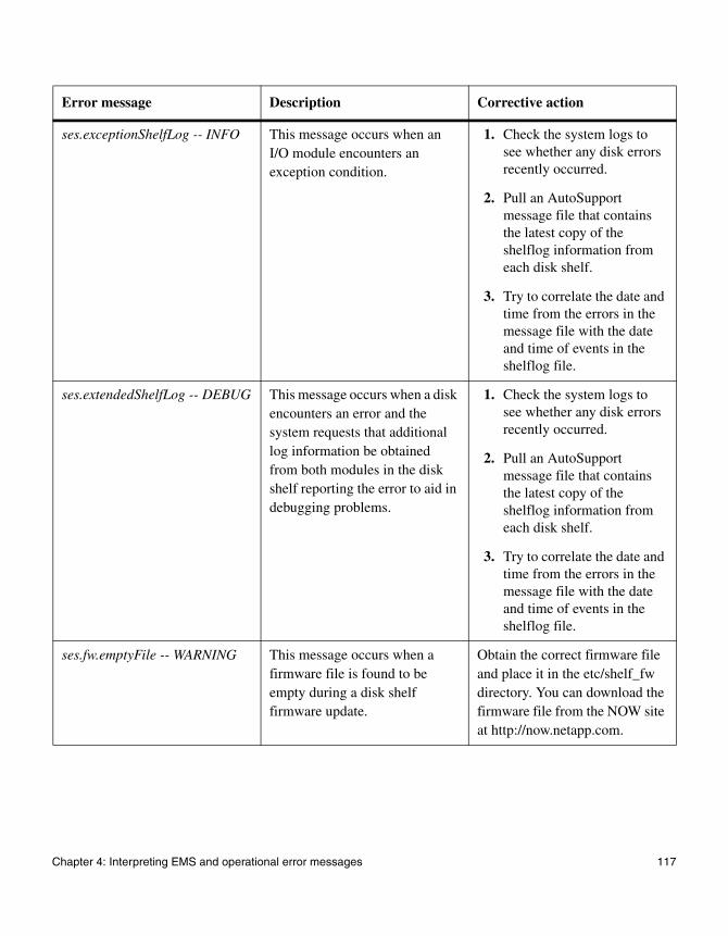
ses.exceptionShelfLog -- INFO This message occurs when an I/O module encounters an exception condition.
1. Check the system logs to see whether any disk errors recently occurred.
2. Pull an AutoSupport message file that contains the latest copy of the shelflog information from each disk shelf.
3. Try to correlate the date and time from the errors in the message file with the date and time of events in the shelflog file.
ses.extendedShelfLog -- DEBUG This message occurs when a disk encounters an error and the system requests that additional log information be obtained from both modules in the disk shelf reporting the error to aid in debugging problems.
1. Check the system logs to see whether any disk errors recently occurred.
2. Pull an AutoSupport message file that contains the latest copy of the shelflog information from each disk shelf.
3. Try to correlate the date and time from the errors in the message file with the date and time of events in the shelflog file.
ses.fw.emptyFile -- WARNING This message occurs when a firmware file is found to be empty during a disk shelf firmware update.
Obtain the correct firmware file and place it in the etc/shelf_fw directory. You can download the firmware file from the NOW site at http://now.netapp.com.
Error message Description Corrective action
Chapter 4: Interpreting EMS and operational error messages 117
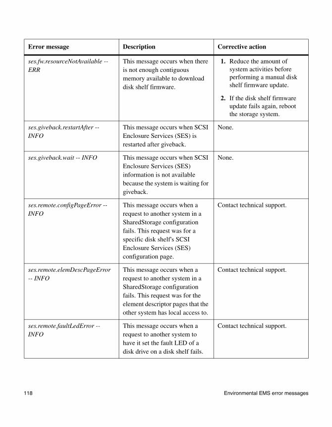
ses.fw.resourceNotAvailable -- ERR
This message occurs when there is not enough contiguous memory available to download disk shelf firmware.
1. Reduce the amount of system activities before performing a manual disk shelf firmware update.
2. If the disk shelf firmware update fails again, reboot the storage system.
ses.giveback.restartAfter -- INFO
This message occurs when SCSI Enclosure Services (SES) is restarted after giveback.
None.
ses.giveback.wait -- INFO This message occurs when SCSI Enclosure Services (SES) information is not available because the system is waiting for giveback.
None.
ses.remote.configPageError -- INFO
This message occurs when a request to another system in a SharedStorage configuration fails. This request was for a specific disk shelf's SCSI Enclosure Services (SES) configuration page.
Contact technical support.
ses.remote.elemDescPageError -- INFO
This message occurs when a request to another system in a SharedStorage configuration fails. This request was for the element descriptor pages that the other system has local access to.
Contact technical support.
ses.remote.faultLedError -- INFO
This message occurs when a request to another system to have it set the fault LED of a disk drive on a disk shelf fails.
Contact technical support.
Error message Description Corrective action
118 Environmental EMS error messages

ses.remote.flashLedError -- INFO
This message occurs when a request to another system to have it flash the LED of a disk drive on a disk shelf fails.
Contact technical support.
ses.remote.shelfListError -- INFO
This message occurs when a request to another system in a SharedStorage configuration fails. This request was for a list of the disk shelves that the other system has local access to.
Contact technical support.
ses.remote.statPageError -- INFO
This message occurs when a request to another system in a SharedStorage configuration fails. This request was for the SCSI Enclosure Services (SES) status pages that the other system has local access to.
Contact technical support.
Error message Description Corrective action
Chapter 4: Interpreting EMS and operational error messages 119
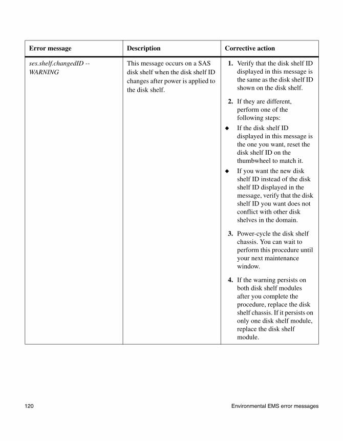
ses.shelf.changedID -- WARNING
This message occurs on a SAS disk shelf when the disk shelf ID changes after power is applied to the disk shelf.
1. Verify that the disk shelf ID displayed in this message is the same as the disk shelf ID shown on the disk shelf.
2. If they are different, perform one of the following steps:
◆ If the disk shelf ID displayed in this message is the one you want, reset the disk shelf ID on the thumbwheel to match it.
◆ If you want the new disk shelf ID instead of the disk shelf ID displayed in the message, verify that the disk shelf ID you want does not conflict with other disk shelves in the domain.
3. Power-cycle the disk shelf chassis. You can wait to perform this procedure until your next maintenance window.
4. If the warning persists on both disk shelf modules after you complete the procedure, replace the disk shelf chassis. If it persists on only one disk shelf module, replace the disk shelf module.
Error message Description Corrective action
120 Environmental EMS error messages

ses.shelf.ctrlFailErr -- SVC_ERROR
This message occurs when the adapter and loop ID of the SCSI Enclosure Services (SES) target for which the SES has control fail.
1. Check the LEDs on the disk shelf and the disk shelf modules on the back of the disk shelf to see whether there are any abnormalities. If the modules appear to be problematic, replace the applicable module.
2. If the SES target is a disk drive, check to see whether the disk drive failed. If it failed, replace the disk drive.
ses.shelf.em.ctrlFailErr -- SVC_ERROR
This message occurs when SCSI Enclosure Services (SES) control to the internal disk drives of a system fails.
Enter environment shelf to see whether that disk shelf is still being actively monitored.
If the environment shelf command indicates a failure, there is a hardware failure in the system's internal disk shelf.
Error message Description Corrective action
Chapter 4: Interpreting EMS and operational error messages 121

ses.shelf.IdBasedAddr -- WARNING
This message occurs on a SAS disk shelf when the SAS addresses of the devices are based on the disk shelf ID instead of the disk shelf backplane serial number. This indicates problems communicating with the disk shelf backplane.
1. Reseat the master disk shelf module, as indicated by the output of the environment shelf command.
2. If the problem persists, reseat the slave disk shelf module.
3. If the problem persists, find the new master disk shelf module and replace it.
4. If the problem persists, replace the other disk shelf module.
5. If the problem persists, replace the disk shelf enclosure.
ses.shelf.invalNum -- WARNING This message occurs when Data ONTAP detects that a Serial Attached SCSI shelf connected to the system has an invalid shelf number.
1. Power-cycle the shelf.
2. If the problem persists, replace the shelf modules.
3. If the problem persists, replace the shelf.
ses.shelf.mmErr -- NODE_FAULT
This message occurs when there is a disk shelf that is not supported by the platform it was booted on.
1. Check whether a newer version of Data ONTAP would solve the problem.
2. If it can’t, power off the system, remove the offending disk shelf, and then reboot.
Error message Description Corrective action
122 Environmental EMS error messages
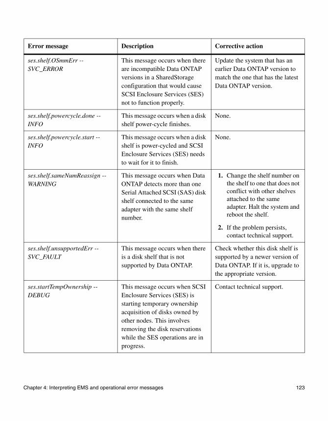
ses.shelf.OSmmErr --SVC_ERROR
This message occurs when there are incompatible Data ONTAP versions in a SharedStorage configuration that would cause SCSI Enclosure Services (SES) not to function properly.
Update the system that has an earlier Data ONTAP version to match the one that has the latest Data ONTAP version.
ses.shelf.powercycle.done -- INFO
This message occurs when a disk shelf power-cycle finishes.
None.
ses.shelf.powercycle.start -- INFO
This message occurs when a disk shelf is power-cycled and SCSI Enclosure Services (SES) needs to wait for it to finish.
None.
ses.shelf.sameNumReassign -- WARNING
This message occurs when Data ONTAP detects more than one Serial Attached SCSI (SAS) disk shelf connected to the same adapter with the same shelf number.
1. Change the shelf number on the shelf to one that does not conflict with other shelves attached to the same adapter. Halt the system and reboot the shelf.
2. If the problem persists, contact technical support.
ses.shelf.unsupportedErr -- SVC_FAULT
This message occurs when there is a disk shelf that is not supported by Data ONTAP.
Check whether this disk shelf is supported by a newer version of Data ONTAP. If it is, upgrade to the appropriate version.
ses.startTempOwnership -- DEBUG
This message occurs when SCSI Enclosure Services (SES) is starting temporary ownership acquisition of disks owned by other nodes. This involves removing the disk reservations while the SES operations are in progress.
Contact technical support.
Error message Description Corrective action
Chapter 4: Interpreting EMS and operational error messages 123

ses.status.ATFCXError -- NODE_ERROR
This message occurs when the reporting disk shelf detects an error in the indicated AT-FCX module. The module might not be able to perform I/O to disks within the disk shelf.
1. Verify that the AT-FCX module is fully seated and secured.
2. If the problem persists, replace the AT-FCX module.
ses.status.ATFCXInfo -- INFO This message occurs when a previously reported error in the AT-FCX module is corrected, or the system reports other information that does not necessarily require customer action.
None.
ses.status.currentError -- NODE_ERROR
This message occurs when a critical condition is detected in the indicated storage shelf current sensor. The shelf might be able to continue operation.
1. Verify that the power supply and the AC line are supplying power.
2. Monitor the power grid for abnormalities.
3. Replace the power supply.
4. If the problem persists, contact technical support.
ses.status.currentInfo -- INFO This message occurs when an error or warning condition previously reported by or about the disk shelf current sensor is corrected, or the system reports other information about the current in the disk shelf that does not necessarily require customer action.
None.
Error message Description Corrective action
124 Environmental EMS error messages
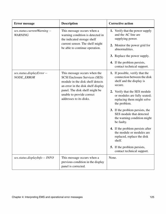
ses.status.currentWarning -- WARNING
This message occurs when a warning condition is detected in the indicated storage shelf current sensor. The shelf might be able to continue operation.
1. Verify that the power supply and the AC line are supplying power.
2. Monitor the power grid for abnormalities.
3. Replace the power supply.
4. If the problem persists, contact technical support.
ses.status.displayError -- NODE_ERROR
This message occurs when the SCSI Enclosure Services (SES) module in the disk shelf detects an error in the disk shelf display panel. The disk shelf might be unable to provide correct addresses to its disks.
1. If possible, verify that the connection between the disk shelf and the display is secure.
2. Verify that the SES module or modules are fully seated; replacing them might solve the problem.
3. If the problem persists, the SES module that detected the warning condition might be faulty.
4. If the problem persists after the module or modules are replaced, replace the disk shelf.
5. If the problem persists, contact technical support.
ses.status.displayInfo -- INFO This message occurs when a previous condition in the display panel is corrected.
None.
Error message Description Corrective action
Chapter 4: Interpreting EMS and operational error messages 125

ses.status.displayWarning -- WARNING
This message occurs when the SCSI Enclosure Services (SES) module detects a warning condition for the disk shelf display panel. The disk shelf might be unable to provide correct addresses to its disks.
1. If possible, verify that the connection between the disk shelf and the display is secure.
2. Verify that the SES module or modules are fully seated; replacing them might solve the problem.
3. If the problem persists, the SES module that detected the warning condition might be faulty.
4. If the problem persists after the module or modules are replaced, replace the disk shelf.
5. If the problem persists, contact technical support.
ses.status.driveError -- NODE_ERROR
This message occurs when a critical condition is detected for the disk drive in the shelf. The drive might fail.
1. Make sure that the drive is not running on a degraded volume. If it is, then add as many spares as necessary into the system, up to the specified level.
2. After the volume is no longer in degraded mode, replace the drive that is failing.
ses.status.driveOk -- INFO This message occurs when a disk drive that was previously experiencing problem returns to normal operation.
None.
Error message Description Corrective action
126 Environmental EMS error messages

ses.status.driveWarning -- NODE_ERROR
This message occurs when a non-critical condition is detected for the disk drive in the shelf. The drive might fail.
1. Make sure that the drive is not running on a degraded volume. If it is, then add as many spares as necessary into the system, up to the specified level.
2. After the volume is no longer in degraded mode, replace the drive that is failing.
ses.status.electronicsError -- NODE_ERROR
This message occurs when a failure has been detected in the module that provides disk SCSI Enclosure Services (SES) monitoring capability.
Replace the module. In some disk shelf types, this function is integrated into the Fibre Channel, SCSI, or Serial Attached SCSI (SAS) interface modules.
ses.status.electronicsInfo -- INFO
This message occurs when a problem previously reported about the disk shelf SCSI Enclosure Services (SES) electronics is corrected or when other information about the enclosure electronics that does not necessarily require customer action is reported.
None.
ses.status.electronicsWarn -- WARNING
This message occurs when a non-fatal condition is detected in the module that provides disk SCSI Enclosure Services (SES) monitoring capability.
Replace the module. In some disk shelf types, this function is integrated into the Fibre Channel, SCSI, or Serial Attached SCSI (SAS) interface modules.
ses.status.ESHPctlStatus -- DEBUG
This message occurs when a change in the power control status is detected in the indicated disk shelf.
None.
Error message Description Corrective action
Chapter 4: Interpreting EMS and operational error messages 127
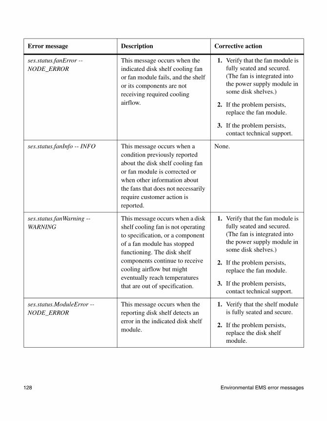
ses.status.fanError -- NODE_ERROR
This message occurs when the indicated disk shelf cooling fan or fan module fails, and the shelf or its components are not receiving required cooling airflow.
1. Verify that the fan module is fully seated and secured. (The fan is integrated into the power supply module in some disk shelves.)
2. If the problem persists, replace the fan module.
3. If the problem persists, contact technical support.
ses.status.fanInfo -- INFO This message occurs when a condition previously reported about the disk shelf cooling fan or fan module is corrected or when other information about the fans that does not necessarily require customer action is reported.
None.
ses.status.fanWarning -- WARNING
This message occurs when a disk shelf cooling fan is not operating to specification, or a component of a fan module has stopped functioning. The disk shelf components continue to receive cooling airflow but might eventually reach temperatures that are out of specification.
1. Verify that the fan module is fully seated and secured. (The fan is integrated into the power supply module in some disk shelves.)
2. If the problem persists, replace the fan module.
3. If the problem persists, contact technical support.
ses.status.ModuleError -- NODE_ERROR
This message occurs when the reporting disk shelf detects an error in the indicated disk shelf module.
1. Verify that the shelf module is fully seated and secure.
2. If the problem persists, replace the disk shelf module.
Error message Description Corrective action
128 Environmental EMS error messages

ses.status.ModuleInfo -- INFO This message occurs when a previously reported error in the shelf module is corrected or when other information that does not necessarily require customer action is reported.
None.
ses.status.ModuleWarn -- WARNING
This message occurs when the reporting disk shelf detects a warning in the indicated disk shelf module.
1. Verify that the shelf module is fully seated and secure.
2. If the problem persists, replace the disk shelf module.
ses.status.psError -- NODE_ERROR
This message occurs when a critical condition is detected in the indicated storage shelf power supply. The power supply might fail.
1. Verify that power input to the shelf is correct. If separate events of this type are reported simultaneously, the common power distribution point might be at fault.
2. If the shelf is in a cabinet, verify that the power distribution unit is ON and functioning properly. Make sure that the shelf power cords are fully inserted and secured, the supply is fully seated and secured, and the supply is switched ON.
3. Verify that power supply fans, if any, are functioning. If the problem persists, replace the power supply.
4. If the problem persists, contact technical support.
Error message Description Corrective action
Chapter 4: Interpreting EMS and operational error messages 129

ses.status.psInfo -- INFO This message occurs when a condition previously reported about the disk shelf power supply is corrected or when other information about the power supply that does not necessarily require customer action is reported.
None.
ses.status.psWarning -- WARNING
This message occurs when a warning condition is detected in the indicated storage shelf power supply. The power supply might be able to continue operation.
1. Verify that the disk shelf is receiving power. If separate events of this type are reported simultaneously, the common power distribution point might be at fault.
2. If the disk shelf is in a cabinet, verify that the power distribution unit status is ON and functioning properly. Make sure that the disk shelf power cords are fully inserted and secured, the power supply is fully seated and secured, and the power supply is switched on.
3. If the problem persists, replace the power supply.
4. If the problem persists, contact technical support.
Error message Description Corrective action
130 Environmental EMS error messages
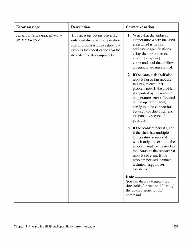
ses.status.temperatureError -- NODE ERROR
This message occurs when the indicated disk shelf temperature sensor reports a temperature that exceeds the specifications for the disk shelf or its components.
1. Verify that the ambient temperature where the shelf is installed is within equipment specifications using the environment shelf [adapter] command, and that airflow clearances are maintained.
2. If the same disk shelf also reports fan or fan module failures, correct that problem now. If the problem is reported by the ambient temperature sensor (located on the operator panel), verify that the connection between the disk shelf and the panel is secure, if possible.
3. If the problem persists, and if the shelf has multiple temperature sensors of which only one exhibits the problem, replace the module that contains the sensor that reports the error. If the problem persists, contact technical support for assistance.
NoteYou can display temperature thresholds for each shelf through the environment shelf command.
Error message Description Corrective action
Chapter 4: Interpreting EMS and operational error messages 131
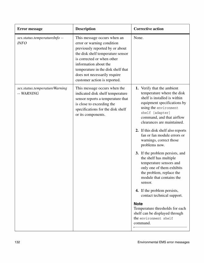
ses.status.temperatureInfo -- INFO
This message occurs when an error or warning condition previously reported by or about the disk shelf temperature sensor is corrected or when other information about the temperature in the disk shelf that does not necessarily require customer action is reported.
None.
ses.status.temperatureWarning -- WARNING
This message occurs when the indicated disk shelf temperature sensor reports a temperature that is close to exceeding the specifications for the disk shelf or its components.
1. Verify that the ambient temperature where the disk shelf is installed is within equipment specifications by using the environment shelf [adapter] command, and that airflow clearances are maintained.
2. If this disk shelf also reports fan or fan module errors or warnings, correct those problems now.
3. If the problem persists, and the shelf has multiple temperature sensors and only one of them exhibits the problem, replace the module that contains the sensor.
4. If the problem persists, contact technical support.
NoteTemperature thresholds for each shelf can be displayed through the environment shelf command.
Error message Description Corrective action
132 Environmental EMS error messages

ses.status.upsError -- NODE_ERROR
This message occurs when the disk shelf detects a failure in the uninterruptible power supply (UPS) attached to it. This might occur, for example, if power to the UPS is lost.
1. Restore power to the UPS.
2. Verify that the connection from the UPS to the disk shelf is in place and secured and that the UPS is enabled.
3. If the problem persists, contact technical support.
ses.status.upsInfo -- INFO This message occurs when a condition previously reported about the UPS attached to the disk shelf is corrected or when other information about the UPS that does not necessarily require customer action is reported.
None.
ses.status.upsWarning -- WARNING
This message occurs when the disk shelf detects a warning condition in the UPS attached to it. This might occur, for example, if power to the UPS is lost.
1. Restore power to the UPS.
2. Verify that the connection from the UPS to the disk shelf is in place and secured and that the UPS is enabled.
3. If the problem persists, contact technical support.
ses.status.volError -- NODE_ERROR
This message occurs when a critical condition is detected in the indicated disk storage shelf voltage sensor. The shelf might be able to continue operation.
1. Verify that the power supply and the AC line are supplying power.
2. Monitor the power grid for abnormalities.
3. Replace the power supply.
4. If the problem persists, contact technical support.
Error message Description Corrective action
Chapter 4: Interpreting EMS and operational error messages 133

ses.status.volInfo -- INFO This message occurs when an error or warning condition previously reported by or about the disk shelf voltage sensor is corrected, or the system reports other information about the voltage in the disk shelf that does not necessarily require customer action.
None.
ses.status.volWarning -- WARNING
This message occurs when a warning condition is detected in the indicated storage shelf voltage sensor. The shelf might be able to continue operation.
1. Verify that the power supply and the AC line are supplying power.
2. Monitor the power grid for abnormalities.
3. Replace the power supply.
4. If the problem persists, contact technical support.
ses.system.em.mmErr -- NODE_FAULT
This message occurs when Data ONTAP does not support this system with internal disk drives.
Check whether this system is currently supported. If it is, upgrade to the appropriate Data ONTAP version.
ses.tempOwnershipDone -- DEBUG
This message occurs when SCSI Enclosure Services (SES) completes temporary ownership acquisition.
Contact technical support.
sfu.adapterSuspendIO -- INFO This message occurs during a disk shelf firmware update on a disk shelf that cannot perform I/O while updating firmware. Typically, the shelves involved are bridge-based as opposed to LRC- or ESH-based.
None.
Error message Description Corrective action
134 Environmental EMS error messages

sfu.ctrllerElmntsPerShelf -- INFO
This message occurs when a disk shelf firmware download determines the number of controller elements per shelf that can be downloaded.
None.
sfu.downloadCtrllerBridge -- INFO
This message occurs when a disk shelf firmware download starts on a particular disk shelf.
None.
sfu.downloadError -- ERR This message occurs when a disk shelf firmware update fails to successfully download firmware to a disk shelf or shelves in the system.
1. Redownload the latest disk shelf firmware from the NOW site at http://now.netapp.com/NOW/download/tools/diskshelf/.
2. Attempt to download disk shelf firmware again by using the storage download shelf command.
sfu.downloadStarted -- INFO This message occurs when a disk shelf firmware update starts to download disk shelf firmware.
None.
sfu.downloadSuccess -- INFO This message occurs when disk shelf firmware is updated successfully.
None.
sfu.downloadSummary -- INFO This message occurs when a disk shelf firmware update is completed successfully.
None.
sfu.downloadSummaryErrors -- ERR
This message occurs when a disk shelf firmware update is completed without successfully downloading to all shelves it attempted.
Issue the storage download shelf command again.
Error message Description Corrective action
Chapter 4: Interpreting EMS and operational error messages 135
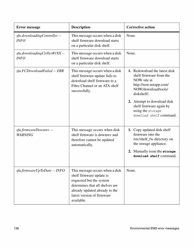
sfu.downloadingController -- INFO
This message occurs when a disk shelf firmware download starts on a particular disk shelf.
None.
sfu.downloadingCtrllerR1XX -- INFO
This message occurs when a disk shelf firmware download starts on a particular disk shelf.
None.
sfu.FCDownloadFailed -- ERR This message occurs when a disk shelf firmware update fails to download shelf firmware to a Fibre Channel or an ATA shelf successfully.
1. Redownload the latest disk shelf firmware from the NOW site at http://now.netapp.com/NOW/download/tools/diskshelf/.
2. Attempt to download disk shelf firmware again by using the storage download shelf command.
sfu.firmwareDownrev -- WARNING
This message occurs when disk shelf firmware is downrev and therefore cannot be updated automatically.
1. Copy updated disk shelf firmware into the /etc/shelf_fw directory on the storage appliance.
2. Manually issue the storage download shelf command.
sfu.firmwareUpToDate -- INFO This message occurs when a disk shelf firmware update is requested but the system determines that all shelves are already updated already to the latest version of firmware available.
None.
Error message Description Corrective action
136 Environmental EMS error messages
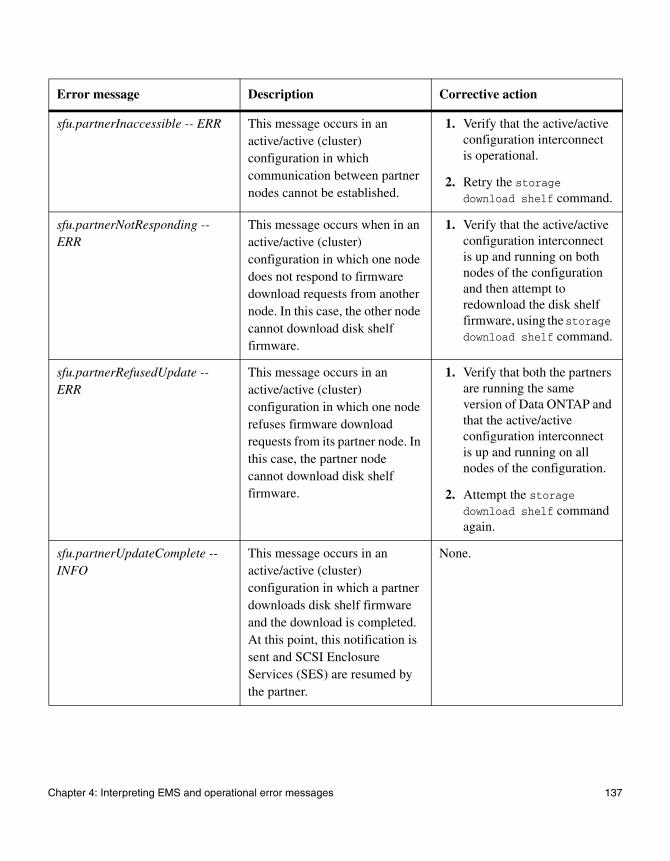
sfu.partnerInaccessible -- ERR This message occurs in an active/active (cluster) configuration in which communication between partner nodes cannot be established.
1. Verify that the active/active configuration interconnect is operational.
2. Retry the storage download shelf command.
sfu.partnerNotResponding -- ERR
This message occurs when in an active/active (cluster) configuration in which one node does not respond to firmware download requests from another node. In this case, the other node cannot download disk shelf firmware.
1. Verify that the active/active configuration interconnect is up and running on both nodes of the configuration and then attempt to redownload the disk shelf firmware, using the storage download shelf command.
sfu.partnerRefusedUpdate -- ERR
This message occurs in an active/active (cluster) configuration in which one node refuses firmware download requests from its partner node. In this case, the partner node cannot download disk shelf firmware.
1. Verify that both the partners are running the same version of Data ONTAP and that the active/active configuration interconnect is up and running on all nodes of the configuration.
2. Attempt the storage download shelf command again.
sfu.partnerUpdateComplete -- INFO
This message occurs in an active/active (cluster) configuration in which a partner downloads disk shelf firmware and the download is completed. At this point, this notification is sent and SCSI Enclosure Services (SES) are resumed by the partner.
None.
Error message Description Corrective action
Chapter 4: Interpreting EMS and operational error messages 137
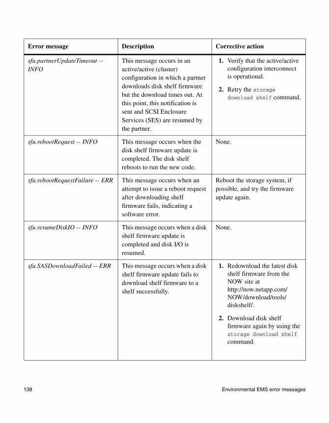
sfu.partnerUpdateTimeout -- INFO
This message occurs in an active/active (cluster) configuration in which a partner downloads disk shelf firmware but the download times out. At this point, this notification is sent and SCSI Enclosure Services (SES) are resumed by the partner.
1. Verify that the active/active configuration interconnect is operational.
2. Retry the storage download shelf command.
sfu.rebootRequest -- INFO This message occurs when the disk shelf firmware update is completed. The disk shelf reboots to run the new code.
None.
sfu.rebootRequestFailure -- ERR This message occurs when an attempt to issue a reboot request after downloading shelf firmware fails, indicating a software error.
Reboot the storage system, if possible, and try the firmware update again.
sfu.resumeDiskIO -- INFO This message occurs when a disk shelf firmware update is completed and disk I/O is resumed.
None.
sfu.SASDownloadFailed -- ERR This message occurs when a disk shelf firmware update fails to download shelf firmware to a shelf successfully.
1. Redownload the latest disk shelf firmware from the NOW site at http://now.netapp.com/NOW/download/tools/diskshelf/.
2. Download disk shelf firmware again by using the storage download shelf command.
Error message Description Corrective action
138 Environmental EMS error messages
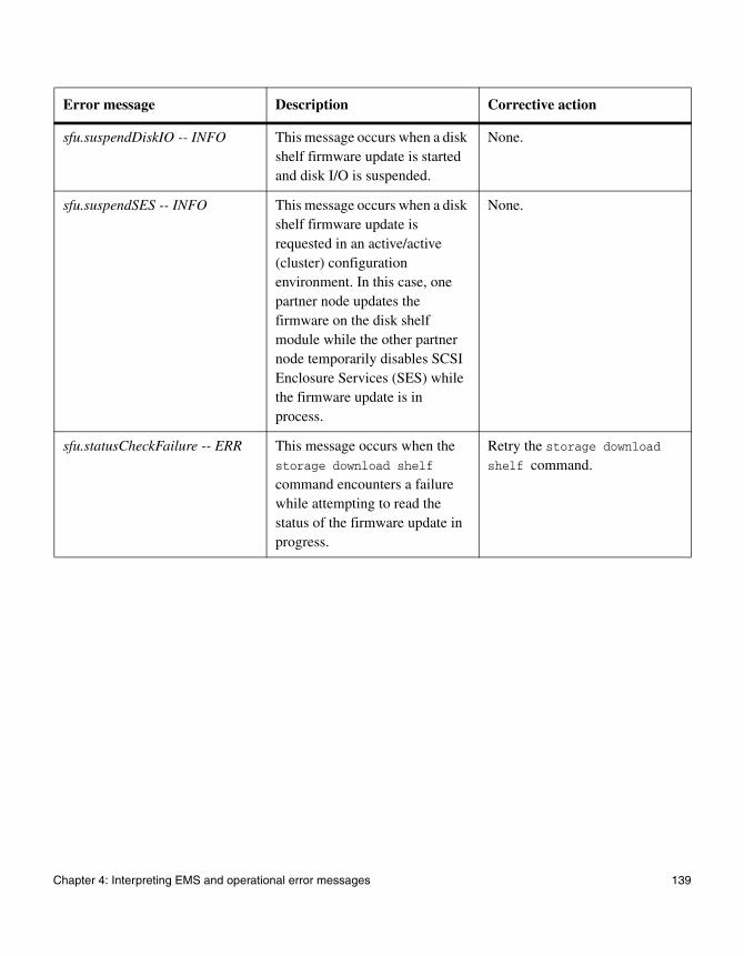
sfu.suspendDiskIO -- INFO This message occurs when a disk shelf firmware update is started and disk I/O is suspended.
None.
sfu.suspendSES -- INFO This message occurs when a disk shelf firmware update is requested in an active/active (cluster) configuration environment. In this case, one partner node updates the firmware on the disk shelf module while the other partner node temporarily disables SCSI Enclosure Services (SES) while the firmware update is in process.
None.
sfu.statusCheckFailure -- ERR This message occurs when the storage download shelf
command encounters a failure while attempting to read the status of the firmware update in progress.
Retry the storage download shelf command.
Error message Description Corrective action
Chapter 4: Interpreting EMS and operational error messages 139

Operational error messages
When operational error messages appear
These error messages might appear on the system console or LCD when the system is operating, when it is halted, or when it is restarting because of system problems.
Operational error messages
The following table describes operational error messages that might appear on the LCD if your system encounters errors while starting up or during operation.
Error message Explanation Fatal? Corrective action
Disk n is broken n—The RAID group disk number. The solution depends on whether you have a hot spare in the system.
No See the appropriate system administration guide for information about how to locate a disk based on the RAID group disk number and how to replace a faulty disk.
Dumping core The system is dumping core after a system crash.
Yes Write down the system crash message on the system console and report the problem to technical support.
Disk hung during swap A disk error occurred as you were hot-swapping a disk.
Yes 1. Disconnect the disk from the power supply by opening the latch and pulling it halfway out.
2. Wait 15 seconds to allow all disks to spin down.
3. Reinstall the disk.
4. Restart the system by entering the following command:
boot
140 Operational error messages

Error dumping core The system cannot dump core during a system crash and restarts without dumping core.
Yes Report the problem to technical support.
Panicking The system is crashing. If the system does not hang while crashing, the message Dumping core appears.
Yes Report the problem to technical support.
FC-AL LINK_FAILURE
Fibre Channel arbitrated loop has link failures.
No Report the problem to technical support.
FC-AL RECOVERABLE ERRORS
Fibre Channel arbitrated loop has been determined to be unreliable. The link errors are recoverable in the sense that the system is still up and running
No Report the problem to technical support.
RMC Alert: Boot Error RMC card sent a DOWN APPLIANCE message. Causes might be a down storage system, a boot error, or an OFN POST error.
Yes Harness script filters them and creates a case.
Contact technical support.
RMC Alert: Down Appliance
RMC card sent a DOWN APPLIANCE message. Causes might be a down storage system, a boot error, or an OFN POST error.
Yes Harness script filters them and creates a case.
Contact technical support.
RMC Alert: OFW POST Error
RMC card sent a DOWN APPLIANCE message. Causes might be a down storage system, a boot error, or an OFN POST error.
Yes Harness script filters them and creates a case.
Contact technical support.
Error message Explanation Fatal? Corrective action
Chapter 4: Interpreting EMS and operational error messages 141

142 Operational error messages
Chapter 5: Understanding Remote LAN Module messages
5
Understanding Remote LAN Module messagesWhat the RLM does The Remote LAN Module (RLM) provides remote platform management capabilities on the following platforms:
◆ FAS3000 series storage systems
◆ V3000 series systems
◆ FAS6000 series storage systems
◆ V6000 series systems
The RLM’s management capabilities include remote access, monitoring, troubleshooting, logging, and alerting features. The RLM extends AutoSupport capabilities by sending alerts or “down system” notification through an AutoSupport message when the system goes down, regardless of whether the system can send AutoSupport messages.
How and when RLM e-mail AutoSupport messages are sent
RLM e-mail notifications are sent to configured recipients designated by the AutoSupport feature. The e-mail notifications have the title “System Notification from the RLM of hostname”, followed by the message type.
Typical RLM-generated AutoSupport messages occur in the following conditions:
◆ The system reboots unexpectedly
◆ The System stops communicating with the RLM
◆ A watchdog reset occurs
◆ The system is power-cycled
◆ Firmware POST errors occur
◆ A user-initiated AutoSupport message occurs
What RLM e-mail notifications include
RLM e-mail messages include the following information:
◆ Subject line—A system notification from the RLM of the system, listing the system condition or event that caused the AutoSupport message and the log level.
◆ In the message body—The RLM configuration and version information, the system ID, serial number, model number, and host name.
◆ In the zipped attachments—The system event logs (SELs), the system sensor state as determined by the RLM, and console logs.
143

RLM-generated messages
The following table describes messages sent by the RLM and the appropriate corrective actions.
RLM message Explanation Action
RLM heartbeat stopped The system software cannot see the Remote LAN Module (RLM).
1. Connect to the RLM command-line interface (CLI) to check whether the RLM is operational.
2. Contact technical support if the problem persists.
RLM HEARTBEAT LOSS
The Remote LAN Module (RLM) detects the loss of heartbeat from Data ONTAP. The system possibly stopped serving data.
1. Connect to the RLM command-line interface (CLI) to check whether the RLM is operational.
2. Contact technical support if the problem persists.
Reboot warning The Remote LAN Module (RLM) detects an abnormal system reboot.
If this was a manually triggered or expected reboot, no action is necessary. Otherwise, complete the following steps.
1. Check the status of the storage system and determine the cause of the reboot.
2. Contact technical support if the storage system fails to reboot.
Heartbeat loss warning The Remote LAN Module (RLM) detects the system is offline, possibly because the system stopped serving data.
If this system shutdown was manually triggered, no action is necessary. Otherwise, complete the following steps.
1. Check the status of your system and verify that the storage system and disk shelves are operational.
2. Contact technical support if the problem persists.
Reboot (power loss) critical
The Remote LAN Module (RLM) detects that the storage system lost AC power.
If you switched off the storage system before you received the notification, no action is necessary. Otherwise, complete the following step.
Restore power to the storage system.
144 Understanding Remote LAN Module messages
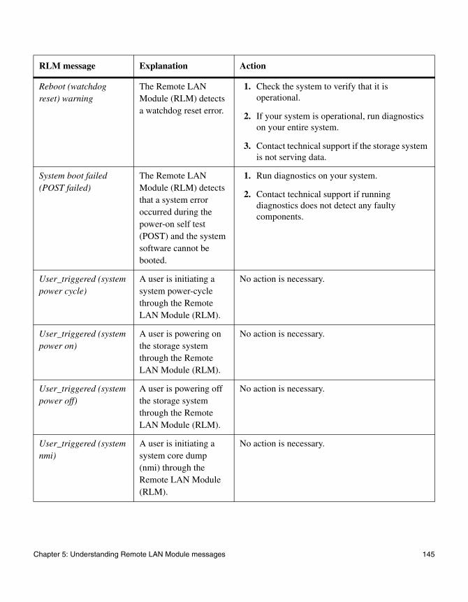
Reboot (watchdog reset) warning
The Remote LAN Module (RLM) detects a watchdog reset error.
1. Check the system to verify that it is operational.
2. If your system is operational, run diagnostics on your entire system.
3. Contact technical support if the storage system is not serving data.
System boot failed (POST failed)
The Remote LAN Module (RLM) detects that a system error occurred during the power-on self test (POST) and the system software cannot be booted.
1. Run diagnostics on your system.
2. Contact technical support if running diagnostics does not detect any faulty components.
User_triggered (system power cycle)
A user is initiating a system power-cycle through the Remote LAN Module (RLM).
No action is necessary.
User_triggered (system power on)
A user is powering on the storage system through the Remote LAN Module (RLM).
No action is necessary.
User_triggered (system power off)
A user is powering off the storage system through the Remote LAN Module (RLM).
No action is necessary.
User_triggered (system nmi)
A user is initiating a system core dump (nmi) through the Remote LAN Module (RLM).
No action is necessary.
RLM message Explanation Action
Chapter 5: Understanding Remote LAN Module messages 145
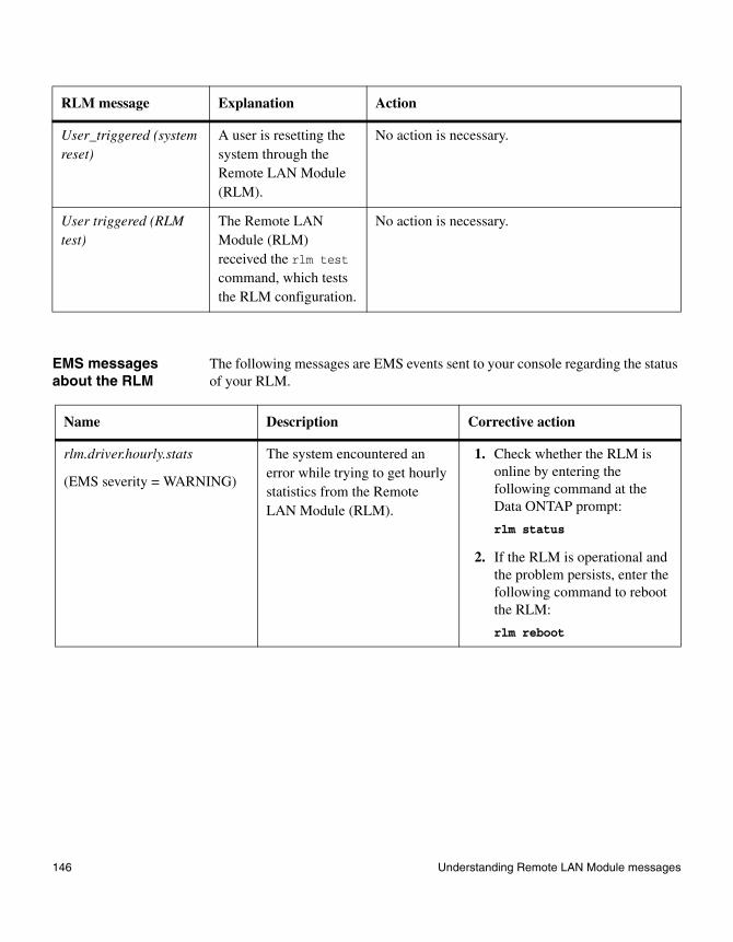
EMS messages about the RLM
The following messages are EMS events sent to your console regarding the status of your RLM.
User_triggered (system reset)
A user is resetting the system through the Remote LAN Module (RLM).
No action is necessary.
User triggered (RLM test)
The Remote LAN Module (RLM) received the rlm test command, which tests the RLM configuration.
No action is necessary.
RLM message Explanation Action
Name Description Corrective action
rlm.driver.hourly.stats
(EMS severity = WARNING)
The system encountered an error while trying to get hourly statistics from the Remote LAN Module (RLM).
1. Check whether the RLM is online by entering the following command at the Data ONTAP prompt:
rlm status
2. If the RLM is operational and the problem persists, enter the following command to reboot the RLM:
rlm reboot
146 Understanding Remote LAN Module messages
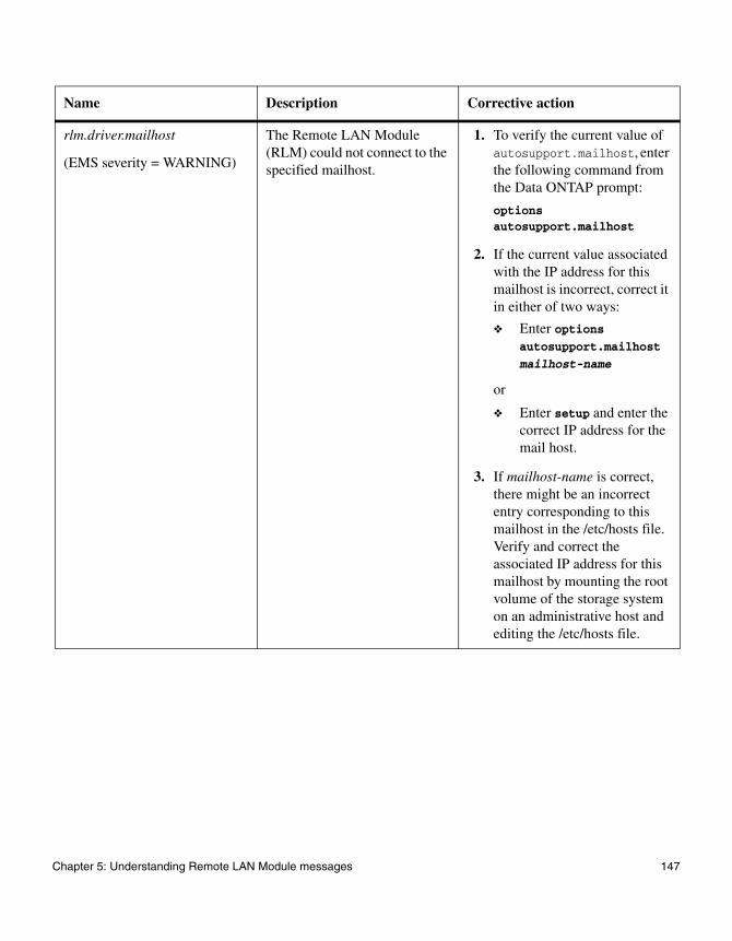
rlm.driver.mailhost
(EMS severity = WARNING)
The Remote LAN Module (RLM) could not connect to the specified mailhost.
1. To verify the current value of autosupport.mailhost, enter the following command from the Data ONTAP prompt:
options autosupport.mailhost
2. If the current value associated with the IP address for this mailhost is incorrect, correct it in either of two ways:
❖ Enter options autosupport.mailhost
mailhost-name
or
❖ Enter setup and enter the correct IP address for the mail host.
3. If mailhost-name is correct, there might be an incorrect entry corresponding to this mailhost in the /etc/hosts file. Verify and correct the associated IP address for this mailhost by mounting the root volume of the storage system on an administrative host and editing the /etc/hosts file.
Name Description Corrective action
Chapter 5: Understanding Remote LAN Module messages 147

rlm.driver.network.failure
(EMS severity = WARNING)
A failure occurred during the network configuration of the Remote LAN Module (RLM). The system could not assign the RLM a Dynamic Host Configuration Protocol (DHCP) or fixed IP address.
1. Check that a network cable is correctly plugged into the RLM network port.
2. Check the link status LED on the RLM.
3. The RLM supports a 10/100 Ethernet network in autonegotiation mode. The network that the RLM is connected to needs to support autonegotiation to 10/100 speed or be running at one of those speeds for the RLM network connectivity to work.
rlm.driver.timeout
(EMS severity = WARNING)
A failure occurred during communication with the Remote LAN Module (RLM).
1. Check whether the RLM is online by entering the following command at the Data ONTAP prompt:
rlm status
2. If the RLM is operational and the problem persists, enter the following command to reboot the RLM:
rlm reboot
Name Description Corrective action
148 Understanding Remote LAN Module messages
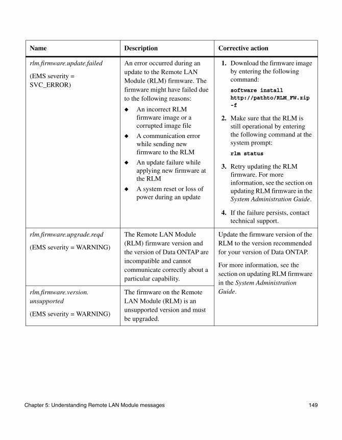
rlm.firmware.update.failed
(EMS severity = SVC_ERROR)
An error occurred during an update to the Remote LAN Module (RLM) firmware. The firmware might have failed due to the following reasons:
◆ An incorrect RLM firmware image or a corrupted image file
◆ A communication error while sending new firmware to the RLM
◆ An update failure while applying new firmware at the RLM
◆ A system reset or loss of power during an update
1. Download the firmware image by entering the following command:
software install http://pathto/RLM_FW.zip -f
2. Make sure that the RLM is still operational by entering the following command at the system prompt:
rlm status
3. Retry updating the RLM firmware. For more information, see the section on updating RLM firmware in the System Administration Guide.
4. If the failure persists, contact technical support.
rlm.firmware.upgrade.reqd
(EMS severity = WARNING)
The Remote LAN Module (RLM) firmware version and the version of Data ONTAP are incompatible and cannot communicate correctly about a particular capability.
Update the firmware version of the RLM to the version recommended for your version of Data ONTAP.
For more information, see the section on updating RLM firmware in the System Administration Guide.rlm.firmware.version.
unsupported
(EMS severity = WARNING)
The firmware on the Remote LAN Module (RLM) is an unsupported version and must be upgraded.
Name Description Corrective action
Chapter 5: Understanding Remote LAN Module messages 149

rlm.heartbeat.bootFromBackup
(EMS severity = WARNING)
The system rebooted the Remote LAN Module (RLM) from its backup firmware to restore RLM availability. The RLM is considered unavailable when the system stops receiving heartbeat notifications from the RLM. To restore availability, the system tries to reboot the RLM from the RLM’s primary firmware. If that fails, the system tries to reboot the RLM from the RLM’s backup firmware. This message is generated if the reboot from backup firmware restores availability.
Update the firmware version of the RLM to the version recommended for your version of Data ONTAP.
For more information, see the section on updating RLM firmware in the System Administration Guide.
rlm.heartbeat.resumed
(EMS severity = INFO)
The storage system detected the resumption of Remote LAN Module (RLM) heartbeat notifications, indicating that the RLM is now available. The earlier issue indicated by the rlm.heartbeat.stopped message was resolved.
None needed.
Name Description Corrective action
150 Understanding Remote LAN Module messages
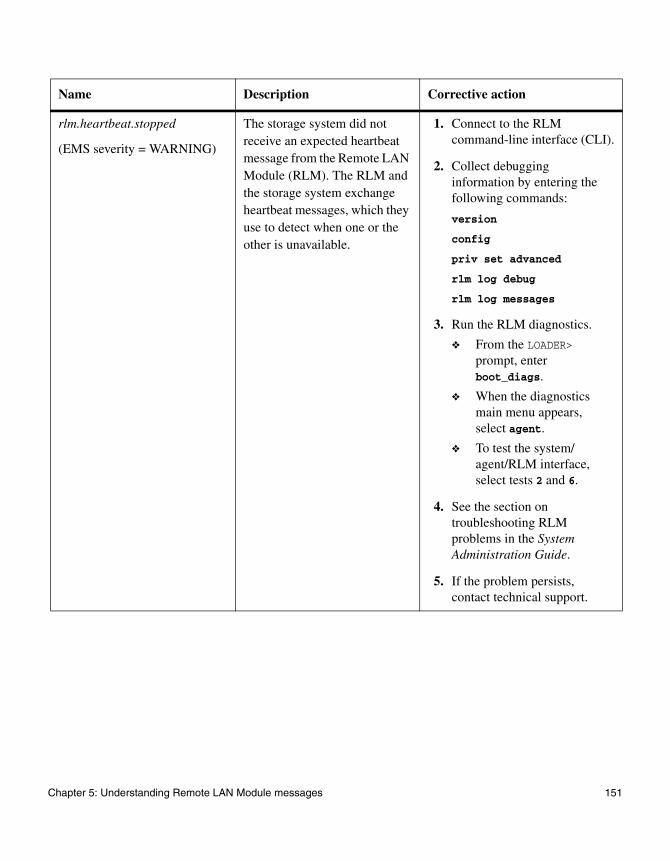
rlm.heartbeat.stopped
(EMS severity = WARNING)
The storage system did not receive an expected heartbeat message from the Remote LAN Module (RLM). The RLM and the storage system exchange heartbeat messages, which they use to detect when one or the other is unavailable.
1. Connect to the RLM command-line interface (CLI).
2. Collect debugging information by entering the following commands:
version
config
priv set advanced
rlm log debug
rlm log messages
3. Run the RLM diagnostics.
❖ From the LOADER> prompt, enter boot_diags.
❖ When the diagnostics main menu appears, select agent.
❖ To test the system/ agent/RLM interface, select tests 2 and 6.
4. See the section on troubleshooting RLM problems in the System Administration Guide.
5. If the problem persists, contact technical support.
Name Description Corrective action
Chapter 5: Understanding Remote LAN Module messages 151
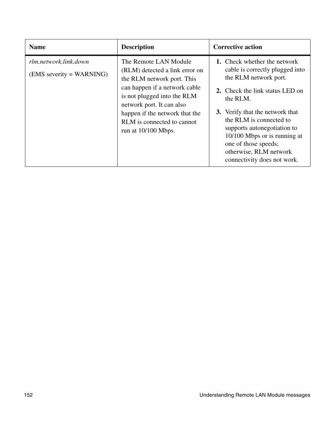
rlm.network.link.down
(EMS severity = WARNING)
The Remote LAN Module (RLM) detected a link error on the RLM network port. This can happen if a network cable is not plugged into the RLM network port. It can also happen if the network that the RLM is connected to cannot run at 10/100 Mbps.
1. Check whether the network cable is correctly plugged into the RLM network port.
2. Check the link status LED on the RLM.
3. Verify that the network that the RLM is connected to supports autonegotiation to 10/100 Mbps or is running at one of those speeds; otherwise, RLM network connectivity does not work.
Name Description Corrective action
152 Understanding Remote LAN Module messages
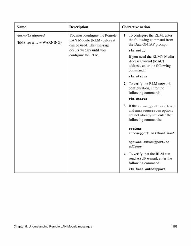
rlm.notConfigured
(EMS severity = WARNING)
You must configure the Remote LAN Module (RLM) before it can be used. This message occurs weekly until you configure the RLM.
1. To configure the RLM, enter the following command from the Data ONTAP prompt:
rlm setup
If you need the RLM’s Media Access Control (MAC) address, enter the following command:
rlm status
2. To verify the RLM network configuration, enter the following command:
rlm status
3. If the autosupport.mailhost and autosupport.to options are not already set, enter the following commands:
options autosupport.mailhost host
options autosupport.to address
4. To verify that the RLM can send ASUP e-mail, enter the following command:
rlm test autosupport
Name Description Corrective action
Chapter 5: Understanding Remote LAN Module messages 153
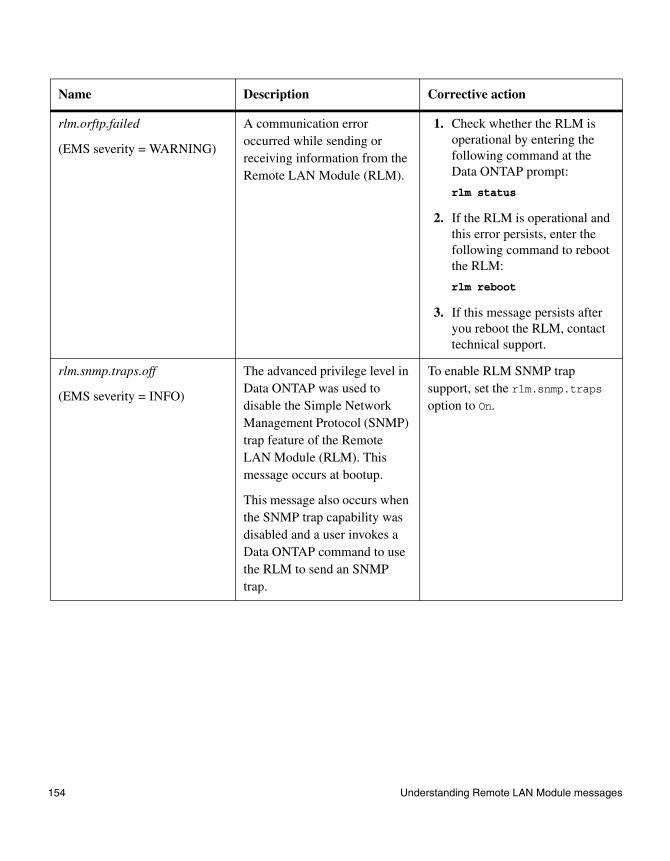
rlm.orftp.failed
(EMS severity = WARNING)
A communication error occurred while sending or receiving information from the Remote LAN Module (RLM).
1. Check whether the RLM is operational by entering the following command at the Data ONTAP prompt:
rlm status
2. If the RLM is operational and this error persists, enter the following command to reboot the RLM:
rlm reboot
3. If this message persists after you reboot the RLM, contact technical support.
rlm.snmp.traps.off
(EMS severity = INFO)
The advanced privilege level in Data ONTAP was used to disable the Simple Network Management Protocol (SNMP) trap feature of the Remote LAN Module (RLM). This message occurs at bootup.
This message also occurs when the SNMP trap capability was disabled and a user invokes a Data ONTAP command to use the RLM to send an SNMP trap.
To enable RLM SNMP trap support, set the rlm.snmp.traps option to On.
Name Description Corrective action
154 Understanding Remote LAN Module messages
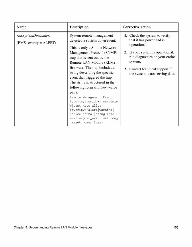
rlm.systemDown.alert
(EMS severity = ALERT)
System remote management detected a system down event.
This is only a Simple Network Management Protocol (SNMP) trap that is sent out by the Remote LAN Module (RLM) firmware. The trap includes a string describing the specific event that triggered the trap. The string is structured in the following form with key=value pairs: Remote Management Event: type={system_down|system_up|test|keep_alive}, severity={alert|warning|notice|normal|debug|info}, event={post_error|watchdog_reset|power_loss}
1. Check the system to verify that it has power and is operational.
2. If your system is operational, run diagnostics on your entire system.
3. Contact technical support if the system is not serving data.
Name Description Corrective action
Chapter 5: Understanding Remote LAN Module messages 155

rlm.systemDown.notice
(EMS severity = NOTICE)
System remote management detected a system down event.
This is only a Simple Network Management Protocol (SNMP) trap that is sent out by the Remote LAN Module (RLM) firmware. The trap includes a string describing the specific event that triggered the trap. The string is structured in the following form with key=value pairs: Remote Management Event: type={system_down|system_up|test|keep_alive}, severity={alert|warning|notice|normal|debug|info}, event={power_off_via_rlm|power_cycle_via_rlm|reset_via_rlm}
1. Check the system to verify that it has power and is operational.
2. If your system is operational, run diagnostics on your entire system.
3. Consult technical support if the system is not serving data.
rlm.systemDown.warning
(EMS severity = WARNING)
System remote management detected a system down event.
This is only a Simple Network Management Protocol (SNMP) trap that is sent out by the Remote LAN Module (RLM) firmware. The trap includes a string describing the specific event that triggered the trap. The string is structured in the following form with key=value pairs: Remote Management Event: type={system_down|system_up|test|keep_alive}, severity={alert|warning|notice|normal|debug|info}, event={loss_of_heartbeat}
1. Check the system to verify that it has power and is operational.
2. If your system is operational, run diagnostics on your entire system.
3. Consult technical support if the system is not serving data.
Name Description Corrective action
156 Understanding Remote LAN Module messages

rlm.systemPeriodic.keepAlive
(EMS severity = INFO)
System remote management sent a periodic keep-alive event.
This is only a Simple Network Management Protocol (SNMP) trap that is sent out by the Remote LAN Module (RLM) firmware. The trap includes a string describing the specific event that triggered the trap. The string is structured in the following form with key=value pairs: Remote Management Event: type={system_down|system_up|test|keep_alive}, severity={alert|warning|notice|normal|debug|info}, event={periodic_message}
None needed.
rlm.systemTest.notice
(EMS severity = NOTICE)
System remote management detected a test event.
This is only a Simple Network Management Protocol (SNMP) trap that is sent out by the Remote LAN Module (RLM) firmware. The trap includes a string describing the specific event that triggered the trap. The string is structured in the following form with key=value pairs: Remote Management Event: type={system_down|system_up|test|keep_alive}, severity={alert|warning|notice|normal|debug|info}, event={test}
None needed.
Name Description Corrective action
Chapter 5: Understanding Remote LAN Module messages 157

rlm.userlist.update.failed
(EMS severity = WARNING)
There was an error while updating user information for the RLM. When user information is updated on Data ONTAP, the RLM is also updated with the new changes. This enables users to log in to the RLM.
1. Check whether the RLM is operational by entering the following command at the Data ONTAP prompt:
rlm status
2. If the RLM is operational and this error persists, reboot the RLM by entering the following command:
rlm reboot
3. Retry the operation that caused the error message.
4. If this message persists after you reboot the RLM, contact technical support.
Name Description Corrective action
158 Understanding Remote LAN Module messages
Chapter 6: Understanding BMC messages
6
Understanding BMC messagesWhat the BMC does The Baseboard Management Controller (BMC) provides remote platform management capabilities on FAS2000 series storage systems. These include remote access, monitoring, troubleshooting, logging, and alerting features.
The BMC sends AutoSupport messages through its independent management interface, regardless of the state of the system.
How and when BMC AutoSupport e-mail notifications are sent
BMC e-mail notifications are sent to configured recipients designated by the AutoSupport feature. The e-mail notifications have the title “System Alert from BMC of filer serial number”, followed by the message type. The serial number is that of the controller with which the BMC is associated.
Typical BMC-generated AutoSupport messages occur under the following conditions:
◆ The system reboots unexpectedly
◆ A system reboot fails
◆ A user-issued action triggers an AutoSupport message
What BMC e-mail notifications include
BMC e-mail notifications include the following information:
◆ Subject line—A system notification from the BMC of the system, listing the system condition or event that cause the AutoSupport message and the log level.
◆ Message body—The IP address, netmask, and other information about the system.
◆ Attachments—System configuration and sensor information.
159

BMC-generated messages
The following table describes messages sent by the BMC and the appropriate corrective actions.
BMC message Explanation Corrective Action
BMC_ASUP_UNKNOWN Unknown Baseboard Management Controller (BMC) error.
Report the problem to technical support.
REBOOT (abnormal) An abnormal reboot occurred.
Verify that the system has returned to operation.
REBOOT (power loss) A power failure was detected, and the system restarted. This occurs when the system is power-cycled by the external switches or in a true power loss.
Verify that the system has returned to operation.
REBOOT (watchdog reset) The system stopped responding and was rebooted by the Baseboard Management Controller (BMC). This occurs when the BMC watchdog is triggered.
Verify that the system has returned to operation.
SYSTEM_BOOT_FAILED (POST failed)
The system failed to pass the BIOS POST. This occurs when the BIOS status sensor is in a failed or hung state.
1. Issue a system reset backup command from the Baseboard Management Controller (BMC) console, and if the system can come up to the boot loader, issue the flash command to update the primary BIOS firmware.
2. If the system is still nonresponsive, contact technical support.
160 Understanding BMC messages
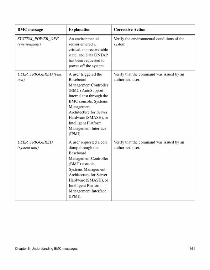
SYSTEM_POWER_OFF (environment)
An environmental sensor entered a critical, nonrecoverable state, and Data ONTAP has been requested to power off the system.
Verify the environmental conditions of the system.
USER_TRIGGERED (bmc test)
A user triggered the Baseboard Management Controller (BMC) AutoSupport internal test through the BMC console, Systems Management Architecture for Server Hardware (SMASH), or Intelligent Platform Management Interface (IPMI).
Verify that the command was issued by an authorized user.
USER_TRIGGERED (system nmi)
A user requested a core dump through the Baseboard Management Controller (BMC) console, Systems Management Architecture for Server Hardware (SMASH), or Intelligent Platform Management Interface (IPMI).
Verify that the command was issued by an authorized user.
BMC message Explanation Corrective Action
Chapter 6: Understanding BMC messages 161

USER_TRIGGERED (system power cycle)
A user issued a power-cycle command through the Baseboard Management Controller (BMC) console, Systems Management Architecture for Server Hardware (SMASH), or Intelligent Platform Management Interface (IPMI).
Verify that the command was issued by an authorized user.
USER_TRIGGERED (system power off)
A user issued a power off command through the Baseboard Management Controller (BMC) console, Systems Management Architecture for Server Hardware (SMASH), or Intelligent Platform Management Interface (IPMI).
Verify that the command was issued by an authorized user.
USER_TRIGGERED (system power soft-off)
A user issued a power soft-off command through the Baseboard Management Controller (BMC) console, Systems Management Architecture for Server Hardware (SMASH), or Intelligent Platform Management Interface (IPMI).
Verify that the command was issued by an authorized user.
BMC message Explanation Corrective Action
162 Understanding BMC messages
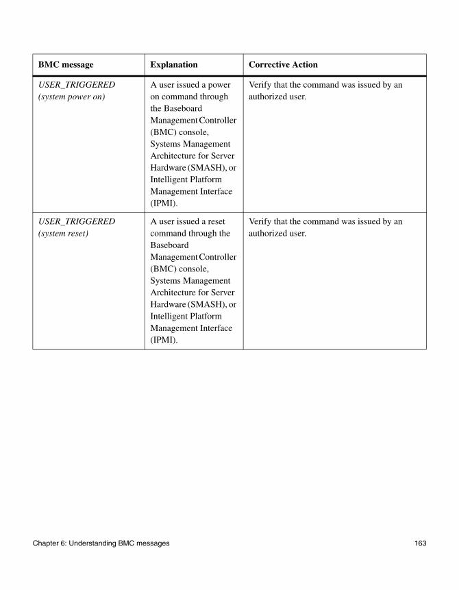
USER_TRIGGERED (system power on)
A user issued a power on command through the Baseboard Management Controller (BMC) console, Systems Management Architecture for Server Hardware (SMASH), or Intelligent Platform Management Interface (IPMI).
Verify that the command was issued by an authorized user.
USER_TRIGGERED (system reset)
A user issued a reset command through the Baseboard Management Controller (BMC) console, Systems Management Architecture for Server Hardware (SMASH), or Intelligent Platform Management Interface (IPMI).
Verify that the command was issued by an authorized user.
BMC message Explanation Corrective Action
Chapter 6: Understanding BMC messages 163
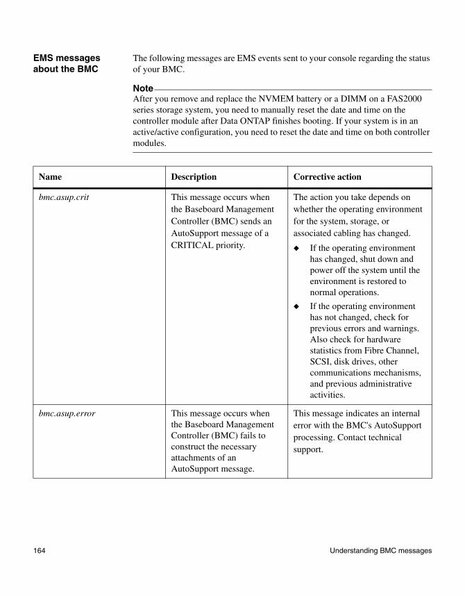
EMS messages about the BMC
The following messages are EMS events sent to your console regarding the status of your BMC.
NoteAfter you remove and replace the NVMEM battery or a DIMM on a FAS2000 series storage system, you need to manually reset the date and time on the controller module after Data ONTAP finishes booting. If your system is in an active/active configuration, you need to reset the date and time on both controller modules.
Name Description Corrective action
bmc.asup.crit This message occurs when the Baseboard Management Controller (BMC) sends an AutoSupport message of a CRITICAL priority.
The action you take depends on whether the operating environment for the system, storage, or associated cabling has changed.
◆ If the operating environment has changed, shut down and power off the system until the environment is restored to normal operations.
◆ If the operating environment has not changed, check for previous errors and warnings. Also check for hardware statistics from Fibre Channel, SCSI, disk drives, other communications mechanisms, and previous administrative activities.
bmc.asup.error This message occurs when the Baseboard Management Controller (BMC) fails to construct the necessary attachments of an AutoSupport message.
This message indicates an internal error with the BMC's AutoSupport processing. Contact technical support.
164 Understanding BMC messages

bmc.asup.init This message occurs when the Baseboard Management Controller (BMC) fails to initialize its AutoSupport subsystem due to a lack of resources.
This message indicates an internal error with the BMC's AutoSupport processing. Contact technical support.
bmc.asup.queue This message occurs when the Baseboard Management Controller (BMC) has too many outstanding AutoSupport messages and no longer has enough resources to service them.
This message might indicate an issue with your AutoSupport configuration.
1. Ensure that your system is configured to use the correct AutoSupport Simple Mail Transfer Protocol (SMTP) mail host, and that the mail host is properly configured to handle AutoSupport messages originating from the BMC.
2. For additional help, contact technical support.
bmc.asup.send This message occurs when the Baseboard Management Controller (BMC) sends an AutoSupport message.
1. Follow the corrective action recommended for the AutoSupport message that was sent.
2. For additional help, contact technical support.
Name Description Corrective action
Chapter 6: Understanding BMC messages 165

bmc.asup.smtp This message occurs when the Baseboard Management Controller (BMC) fails to contact the mailhost when attempting to send an AutoSupport message.
This message indicates an issue with your AutoSupport configuration.
1. Ensure that your system is configured to use the correct AutoSupport Simple Mail Transfer Protocol (SMTP) mail host and that the mail host is properly configured to handle AutoSupport messages originating from the BMC.
2. For additional help, contact technical support.
bmc.batt.id This message occurs when the Baseboard Management Controller (BMC) cannot read the part number information stored in the battery configuration firmware.
Contact technical support for the current procedure to determine whether the battery failed.
bmc.batt.invalid This message occurs when the Baseboard Management Controller (BMC) determines that the battery installed is not the correct model for your system.
Contact technical support to request the appropriate replacement battery for your model of system.
bmc.batt.mfg This message occurs when the Baseboard Management Controller (BMC) cannot read the manufacturer information stored in the battery configuration firmware.
Contact technical support for the current procedure to determine whether the battery failed.
Name Description Corrective action
166 Understanding BMC messages

bmc.batt.rev This message occurs when the Baseboard Management Controller (BMC) cannot read the revision code stored in the battery configuration firmware.
Contact technical support for the current procedure to determine whether the battery failed.
bmc.batt.seal This message occurs when the Baseboard Management Controller (BMC) cannot seal the battery's configuration information after a battery upgrade.
Contact technical support for the current procedure to determine whether the battery failed.
bmc.batt.unknown This message occurs when the Baseboard Management Controller (BMC) determines that the installed battery is not a recognized part that is approved for use in your system.
Contact technical support to request the appropriate replacement battery for your model of system.
bmc.batt.unseal This message occurs when the Baseboard Management Controller (BMC) cannot unseal the battery's configuration information to determine whether the battery firmware requires an upgrade.
Contact technical support for the current procedure to determine whether the battery failed.
bmc.batt.upgrade.busy This message occurs when the Baseboard Management Controller (BMC) determines that the battery configuration firmware requires an upgrade, but that the BMC is too busy to perform the upgrade.
It is normal to get this message one time after a BMC upgrade. However, if this message is issued more than once, it indicates a problem with your system. Contact technical support for the current procedure to determine whether your system needs to be replaced.
Name Description Corrective action
Chapter 6: Understanding BMC messages 167
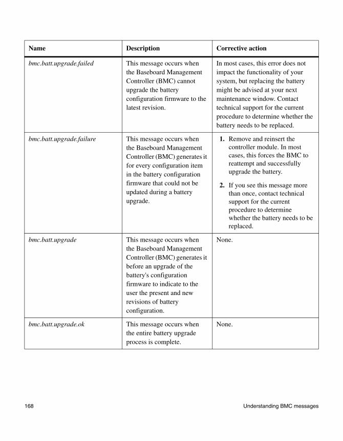
bmc.batt.upgrade.failed This message occurs when the Baseboard Management Controller (BMC) cannot upgrade the battery configuration firmware to the latest revision.
In most cases, this error does not impact the functionality of your system, but replacing the battery might be advised at your next maintenance window. Contact technical support for the current procedure to determine whether the battery needs to be replaced.
bmc.batt.upgrade.failure This message occurs when the Baseboard Management Controller (BMC) generates it for every configuration item in the battery configuration firmware that could not be updated during a battery upgrade.
1. Remove and reinsert the controller module. In most cases, this forces the BMC to reattempt and successfully upgrade the battery.
2. If you see this message more than once, contact technical support for the current procedure to determine whether the battery needs to be replaced.
bmc.batt.upgrade This message occurs when the Baseboard Management Controller (BMC) generates it before an upgrade of the battery's configuration firmware to indicate to the user the present and new revisions of battery configuration.
None.
bmc.batt.upgrade.ok This message occurs when the entire battery upgrade process is complete.
None.
Name Description Corrective action
168 Understanding BMC messages

bmc.batt.upgrade.power-off This message occurs in the rare event where the Baseboard Management Controller (BMC) cannot turn on system power, and the battery has not been checked to determine whether it requires a configuration upgrade.
1. Remove and reinsert the controller module.
2. If you continue to see this message, contact technical support for the current procedure to determine whether the controller module needs to be replaced.
bmc.batt.upgrade.voltagelow This message occurs when the Baseboard Management Controller (BMC) generates it because the battery is discharged to below 6.0V and the battery requires a configuration firmware update.
This message is printed every 10 minutes until the battery is recharged. If you continue to see this message after one hour, contact technical support for the current procedure to determine whether the battery needs to be replaced.
bmc.batt.voltage This message occurs in the rare event where the Baseboard Management Controller (BMC) determines that the battery configuration firmware requires an update and the battery is successfully prepared for the update, but the BMC cannot read the battery voltage sensor.
Contact technical support for the current procedure to determine whether the battery needs to be replaced.
Name Description Corrective action
Chapter 6: Understanding BMC messages 169

bmc.config.asup.off This message occurs in the rare event that the Baseboard Management Controller (BMC) detects corruption in the BMC's internal cached copy of the AutoSupport mail host and/or configured destinations. AutoSupport messages from the BMC are disabled until the system boots.
Boot the system to ensure that the BMC's cache of the AutoSupport configuration is correct.
bmc.config.corrupted This message occurs in the rare event that the Baseboard Management Controller (BMC) internal configuration is corrupted and is being reset to defaults. Notably, the Secure Shell (SSH) service on the BMC LAN interface is disabled until the system boots.
1. Boot the system. Upon boot, the SSH host keys for the BMC are regenerated. The previous host keys for the BMC are no longer valid and cannot be used for logins.
2. Contact technical support to determine whether your system needs maintenance.
bmc.config.default This message occurs in the rare event that the Baseboard Management Controller (BMC) internal configuration is corrupted and is being reset to defaults. Notably, the Secure Shell (SSH) service on the BMC LAN interface is disabled until the system boots.
1. Boot the system. Upon boot, the SSH host keys for the BMC are regenerated. The previous host keys for the BMC are no longer valid and cannot be used for logins.
2. Contact technical support to determine whether your system needs maintenance.
Name Description Corrective action
170 Understanding BMC messages

bmc.config.default.pef.filter This message occurs in the rare event that the Baseboard Management Controller (BMC) internal configuration is corrupted and is being reset to defaults. Notably, the BMC's Platform Event Filter (PEF) tables are being cleared to factory defaults.
Most users need to take no action. However, if you want to use custom Intelligent Platform Management Interface (IPMI) PEF tables, you need to reenable the BMC IPMI LAN interface, and reload any custom PEF tables that might be defined for your site.
bmc.config.default.pef.policy This message occurs in the rare event that the Baseboard Management Controller (BMC) internal configuration is corrupted and is being reset to defaults. Notably, the BMC's Platform Event Filter (PEF) tables are being cleared to factory defaults.
Most users need to take no action. However, if you want to use custom Intelligent Platform Management Interface (IPMI) PEF tables, you need to reenable the BMC IPMI LAN interface, and reload any custom PEF tables that might be defined for your site.
bmc.config.fru.systemserial This message occurs when the Baseboard Management Controller (BMC) detects an invalid System Serial Number field in the system’s Field-Replaceable Unit (FRU) configuration area.
Contact technical support to determine the maintenance procedure for your system.
bmc.config.mac.error This message occurs when the Baseboard Management Controller (BMC) Ethernet MAC identifier is invalid.
Contact technical support to determine the corrective procedure for your system.
bmc.config.net.error This message occurs when the Baseboard Management Controller (BMC) cannot start networking support on the BMC LAN interface.
Contact technical support to determine the corrective procedure for your system.
Name Description Corrective action
Chapter 6: Understanding BMC messages 171
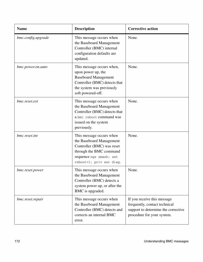
bmc.config.upgrade This message occurs when the Baseboard Management Controller (BMC) internal configuration defaults are updated.
None.
bmc.power.on.auto This message occurs when, upon power up, the Baseboard Management Controller (BMC) detects that the system was previously soft powered-off.
None.
bmc.reset.ext This message occurs when the Baseboard Management Controller (BMC) detects that a bmc reboot command was issued on the system previously.
None.
bmc.reset.int This message occurs when the Baseboard Management Controller (BMC) was reset through the BMC command sequence ngs smash; set reboot=1; priv set diag.
None.
bmc.reset.power This message occurs when the Baseboard Management Controller (BMC) detects a system power up, or after the BMC is upgraded.
None.
bmc.reset.repair This message occurs when the Baseboard Management Controller (BMC) detects and corrects an internal BMC error.
If you receive this message frequently, contact technical support to determine the corrective procedure for your system.
Name Description Corrective action
172 Understanding BMC messages

bmc.reset.unknown This message occurs when the Baseboard Management Controller (BMC) cannot determine why it was reset.
This message usually indicates a BMC internal error. Contact technical support to determine the corrective procedure for your system.
bmc.sensor.batt.charger.off This message occurs when the Baseboard Management Controller (BMC) detects that the battery charger cannot be disabled for the hourly battery load test.
Contact technical support to determine the corrective procedure for your system.
bmc.sensor.batt.charger.on This message occurs when the Baseboard Management Controller (BMC) cannot reenable the battery charger after the hourly battery load test.
Contact technical support to determine the corrective procedure for your system.
bmc.sensor.batt.time.run.invalid This message occurs when the Baseboard Management Controller (BMC) detects that the battery's calculated run time differs substantially from the battery's run-time sensor.
None.
bmc.ssh.key.missing This message occurs when the Baseboard Management Controller (BMC) detects that the Secure Shell (SSH) host keys for the BMC are corrupted or missing.
Reboot the system. The boot sequence regenerates the host key and makes the BMC SSH service available again.
Name Description Corrective action
Chapter 6: Understanding BMC messages 173

174 Understanding BMC messages
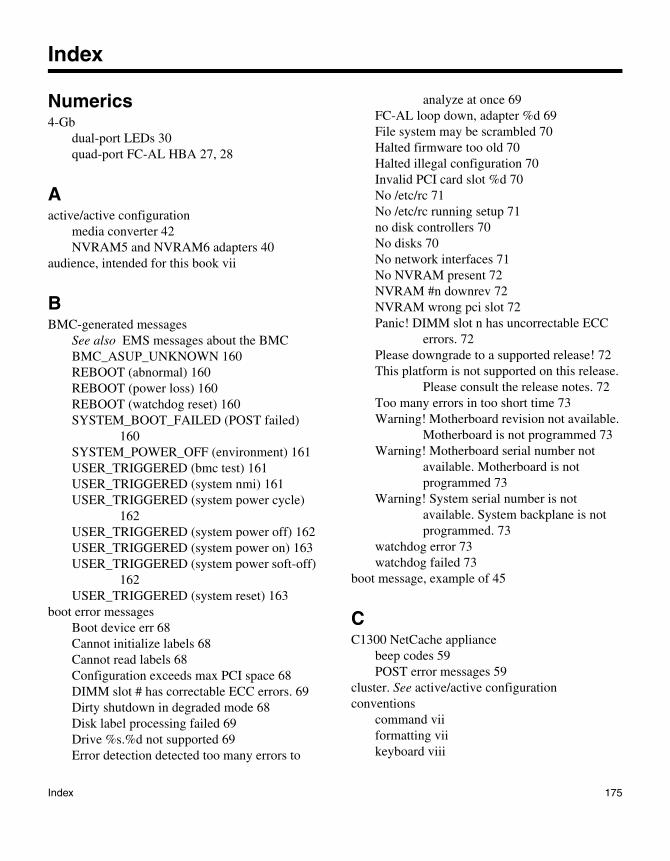
Index
Numerics4-Gb
dual-port LEDs 30quad-port FC-AL HBA 27, 28
Aactive/active configuration
media converter 42NVRAM5 and NVRAM6 adapters 40
audience, intended for this book vii
BBMC-generated messages
See also EMS messages about the BMCBMC_ASUP_UNKNOWN 160REBOOT (abnormal) 160REBOOT (power loss) 160REBOOT (watchdog reset) 160SYSTEM_BOOT_FAILED (POST failed)
160SYSTEM_POWER_OFF (environment) 161USER_TRIGGERED (bmc test) 161USER_TRIGGERED (system nmi) 161USER_TRIGGERED (system power cycle)
162USER_TRIGGERED (system power off) 162USER_TRIGGERED (system power on) 163USER_TRIGGERED (system power soft-off)
162USER_TRIGGERED (system reset) 163
boot error messagesBoot device err 68Cannot initialize labels 68Cannot read labels 68Configuration exceeds max PCI space 68DIMM slot # has correctable ECC errors. 69Dirty shutdown in degraded mode 68Disk label processing failed 69Drive %s.%d not supported 69Error detection detected too many errors to
analyze at once 69FC-AL loop down, adapter %d 69File system may be scrambled 70Halted firmware too old 70Halted illegal configuration 70Invalid PCI card slot %d 70No /etc/rc 71No /etc/rc running setup 71no disk controllers 70No disks 70No network interfaces 71No NVRAM present 72NVRAM #n downrev 72NVRAM wrong pci slot 72Panic! DIMM slot n has uncorrectable ECC
errors. 72Please downgrade to a supported release! 72This platform is not supported on this release.
Please consult the release notes. 72Too many errors in too short time 73Warning! Motherboard revision not available.
Motherboard is not programmed 73Warning! Motherboard serial number not
available. Motherboard is not programmed 73
Warning! System serial number is not available. System backplane is not programmed. 73
watchdog error 73watchdog failed 73
boot message, example of 45
CC1300 NetCache appliance
beep codes 59POST error messages 59
cluster. See active/active configurationconventions
command viiformatting viikeyboard viii
Index 175

Ddegraded power, possible cause and remedy 107dual-port, 4-GbFC-AL HBA LEDs 30
EEMS error messages
See also EMS messages about the BMC, EMS messages about the RLM, environmental EMS error messages, and SES EMS error messages
ds.sas.config.warning 83ds.sas.crc.err 83ds.sas.drivephy.disableErr 84ds.sas.element.fault 85ds.sas.element.xport.error 85ds.sas.hostphy.disableErr 86ds.sas.invalid.word 86ds.sas.loss.dword 87ds.sas.multPhys.disableErr 87ds.sas.phyRstProb 87ds.sas.running.disparity 87ds.sas.ses.disableErr 88ds.sas.xfer.export.error 89ds.sas.xfer.not.sent 90ds.sas.xfer.unknown.error 90ds.sas.xfer.xfer.element.fault 89sas.adapter.bad 90sas.adapter.bootarg.option 90sas.adapter.debug 90sas.adapter.exception 91sas.adapter.failed 91sas.adapter.firmware.download 91sas.adapter.firmware.fault 91sas.adapter.firmware.update.failed 91sas.adapter.not.ready 92sas.adapter.offline 92sas.adapter.offlining 92sas.adapter.online 92sas.adapter.online.failed 92sas.adapter.onlining 92sas.adapter.reset 93sas.adapter.unexpected.status 93sas.config.mixed.tetected 93sas.device.invalid.wwn 93
sas.device.quiesce 94sas.device.resetting 94sas.device.timeout 95sas.initialization.failed 95sas.link.error 96sasmon.adapter.phy.disable 97sasmon.adapter.phy.event 96sasmon.disable.module 97
EMS messages about the BMCbmc.asup.crit 164bmc.asup.error 164bmc.asup.init 165bmc.asup.queue 165bmc.asup.send 165bmc.asup.smtp 166bmc.batt.id 166bmc.batt.invalid 166bmc.batt.mfg 166bmc.batt.rev 167bmc.batt.seal 167bmc.batt.unknown 167bmc.batt.unseal 167bmc.batt.upgrade 168bmc.batt.upgrade.busy 167bmc.batt.upgrade.failed 168bmc.batt.upgrade.failure 168bmc.batt.upgrade.ok 168bmc.batt.upgrade.power-off 169bmc.batt.upgrade.voltagelow 169bmc.batt.voltage 169bmc.config.asup.off 170bmc.config.corrupted 170bmc.config.default 170bmc.config.default.pef.filter 171bmc.config.default.pef.policy 171bmc.config.fru.systemserial 171bmc.config.mac.error 171bmc.config.net.error 171bmc.config.upgrade 172bmc.power.on.auto 172bmc.reset.ext 172bmc.reset.int 172bmc.reset.power 172bmc.reset.repair 172bmc.reset.unknown 173
176 Index

bmc.sensor.batt.charger.off 173bmc.sensor.batt.charger.on 173bmc.sensor.batt.time.run.invalid 173bmc.ssh.key.missing 173
EMS messages about the RLMrlm.driver.hourly.stats 146rlm.driver.mailhost 147rlm.driver.network.failure 148rlm.driver.timeout 148rlm.firmware.update.failed 149rlm.firmware.upgrade.reqd 149rlm.firmware.version.unsupported 149rlm.heartbeat.bootFromBackup 150rlm.heartbeat.resumed 150rlm.heartbeat.stopped 151rlm.network.link.down 152rlm.notConfigured 153rlm.orftp.failed 154rlm.snmp.traps.off 154rlm.systemDown.alert 155rlm.systemDown.notice 156rlm.systemDown.waiting 156rlm.systemPeriodic.keepAlive 157rlm.systemTest.notice 157rlm.userlist.update.failed 158
environmental EMS error messagesfans stopped; replace them 103monitor.chassisFan.ok 104monitor.chassisFan.removed 104monitor.chassisFan.slow 105monitor.chassisFan.stop 105monitor.chassisPower.degraded 105monitor.chassisPower.ok 105monitor.chassisPowerSupplies.ok 105monitor.chassisPowerSupply.degraded 106monitor.chassisPowerSupply.notPresent(ps_n
umber: INT) 106monitor.chassisPowerSupply.off(ps_number:
INT) 106monitor.chassisTemperature.cool 106monitor.chassisTemperature.ok 106monitor.chassisTemperature.warm 106monitor.cpuFan.degraded(cpu_number: INT)
107monitor.cpuFan.failed(cpu_number: INT) 107
monitor.cpuFan.ok(cpu_number: INT) 107monitor.shutdown.chassisOverTemp 107monitor.shutdown.chassisUnderTemp 107power supply degraded 98, 99, 101temperature exceeds limits 102
error messagesSee boot error messages 68See EMS error messages 83See environmental EMS error messages 98See FAS2000 AutoSupport error messages 76See operational error messages 140See POST error messages 48, 51
FFAS2000 series AutoSupport error messages
BATTERY LOW 76BATTERY OVER TEMPERATURE 76BMC HEARTBEAT STOPPED 77CHASSIS FAN FAIL 77CHASSIS FAN FRU DEGRADED 78CHASSIS FAN FRU FAILED 78CHASSIS FAN FRU REMOVED 78CHASSIS OVER TEMPERATURE 78CHASSIS OVER TEMPERATURE
SHUTDOWN 78CHASSIS POWER DEGRADED 79CHASSIS POWER SHUTDOWN 79CHASSIS POWER SUPPLIES MISMATCH
79CHASSIS POWER SUPPLY %d
REMOVED: System will be shutdown in %d minutes 79
CHASSIS POWER SUPPLY DEGRADED 79CHASSIS POWER SUPPLY FAIL 79CHASSIS POWER SUPPLY OFF
PS%d 79CHASSIS POWER SUPPLY OK 79CHASSIS POWER SUPPLY REMOVED 79CHASSIS POWER SUPPLY: Incompatible
external power source 79CHASSIS UNDER TEMPERATURE 80CHASSIS UNDER TEMPERATURE
SHUTDOWN 80DISK PORT FAIL 80
Index 177

ENCLOSURE SERVICES ACCESS ERROR 80
HOST PORT FAIL 80MULTIPLE CHASSIS FAN FAILED
System will shut down in %d minutes 80MULTIPLE FAN FAILURE 80NVMEM_VOLTAGE_ TOO_HIGH 80NVMEM_VOLTAGE_ TOO_LOW 80POSSIBLE BAD RAM 81POWER_SUPPLY_FAIL 81PS #1(2) Failed
POWER_SUPPLY_DEGRADED 81SHELF COOLING UNIT FAILED 81SHELF OVER TEMPERATURE 82SHELF POWER INTERRUPTED 82SHELF POWER SUPPLY WARNING 82SHELF_FAULT 81SYSTEM CONFIGURATION ERROR
(SYSTEM_ CONFIGURATION_ CRITICAL_ERROR) 82
SYSTEM CONFIGURATION WARNING 82FAS2000 series date resetting 76, 164FAS2000 series DIMM replacement 76, 164FAS2000 series NVMEM battery replacement 76, 164Fibre Channel HBA LEDs 26Fibre Channel port LEDs
FAS3000 series systems 15FAS6000 series systems 19
GGbE network
GbE NICs LEDs 35GbE NIC
LEDs 33GbE port LEDs
FAS3000 series 15FAS6000 series 19
HHBAs
LEDs 26types 26
Iinstallation
startup error messages 44iSCSI HBA
LEDs 26
LLEDs
behavior and onboard drive failures, FAS2000 systems 11
C3300 NetCache appliance LEDs visible from the front
FAS3000 series LEDs visible from the front 13
dual-port Fibre Channel HBA 26dual-port TOE NICs, 10GBase-CX4 38dual-port TOE NICs, 10GBase-SR 37dual-port, 4-Gb FC-AL HBA 30dual-port, 4-Gb, target mode, Fibre Channel
HBA 30FAS2000 series LEDs visible from the back 8FAS2000 series LEDs visible from the front 7FAS3000 series LEDs visible from the back 15FAS3000 series onboard Fibre Channel ports
15FAS3000 series onboard GbE ports 15FAS3000 series RLM 15FAS6000 onboard Fibre Channel ports 19FAS6000 series appliance LEDs visible from
the front 18FAS6000 series LEDs visible from the back 19FAS6000 series onboard GbE ports 19FAS6000 series RLM 19Fibre Channel HBA 26GbE NIC 33, 35iSCSI HBA 26iSCSI target HBA 31multiport NIC 34NVRAM5 adapter 40NVRAM5 cluster interconnect adapter 40NVRAM5 media converter 42NVRAM6 adapter 40NVRAM6 media converter 42power supply 10
178 Index
quad-port TOE NIC 39quad-port, 4-Gb FC-AL HBA 27, 28quad-port, 4-Gb, Fibre Channel HBA (12 LED
version) 28quad-port, 4-Gb, Fibre Channel HBA (four
LED version) 27single-port TOE NIC 36
Mmessages
See boot error messages 68See EMS error messages 83See environmental EMS error messages 98See operational error messages 140See POST error messages 48, 51
multiport NICLEDs 34
NNVMEM
status LED, what not to do when blinking 10what not to do when armed 10
NVRAM5 adapterLEDs on NVRAM5 adapter 40media converter LEDs 42which systems support the 40
NVRAM5 cluster interconnect adapterLEDs on NVRAM5 cluster interconnect
adapter 40NVRAM6 adapter
LEDs on NVRAM6 adapter 40media converter LEDs 42which systems support the 40
Ooperational error messages
Disk hung during swap 140Disk n is broken 140Dumping core 140Error dumping core 141FC-AL LINK_FAILURE 141FC-AL RECOVERABLE ERRORS 141Panicking 141
RMC AlertBoot Error 141Down Appliance 141OFW POST Error 141
PPOST error messages
0200: Failure Fixed Disk 510230: System RAM Failed at offset: 520231: Shadow RAM failed at offset 520232: Extended RAM failed at address line 52023E: Node Memory Interleaving disabled 520241: Agent Read Timeout 530242: Invalid FRU information 540250: System battery is dead--Replace and run
SETUP 540251: System CMOS checksum bad--Default
configuration used 540253: Clear CMOS jumper detected--Please
remove for normal operation 550260: System timer error 550280: Previous boot incomplete–Default
configuration used 5502C2: No valid Boot Loader in System Flash--
Non Fatal 5502C3: No valid Boot Loader in System Flash--
Fatal 5602F9: FGPA jumper detected--Please remove
for normal operation 5602FA: Watchdog Timer Reboot ‹PciInit› 5702FB: Watchdog Timer Reboot ‹MemTest› 5702Fb: Watchdog Timer Reboot ‹MemTest› 5702FC: LDTStop Reboot ‹HTLinkInit› 58Abort Autoboot--POST Failure(s) CPU 49Abort Autoboot--POST Failure(s) MEMORY
49Abort Autoboot--POST Failure(s) RTC,
RTC_IO 49Abort Autoboot--POST Failure(s) UCODE 49Autoboot of Back up image failed Autoboot of
primary image failed 50Autoboot of backup image aborted 49Autoboot of primary image aborted 49Bad DIMM found in slot # 52
Index 179

Boot failure 64C1300 NetCache appliance 59CMOS battery low 66CMOS checksum bad 66CMOS date/time not set 66CMOS settings wrong 66drive failure 64Drive not ready 64Gate20 error 64Insert BOOT diskette in A 64Interrupt controller-N error 66Invalid boot diskette 64Invalid FRU EEPROM Checksum 49Keyboard error 67Keyboard/interface error 67Memory init failure Data segment does not
compare at XXXX 48Multi-bit ECC erro 64Multiple-bit ECC error occurred 52No Memory found 48NVRAM bad 66NVRAM ignored 66Parity error 64PCI I/O conflict 66PCI IRQ conflict 66PCI IRQ routing table error 66PCI ROM conflict 66Resource conflict 65Static resource conflict 65System halted 67Timer error 66Unsupported system bus speed 0xXXXX
defaulting to 1000Mhz 48POST messages
about 44POST messages, example of 44
Qquad-port, 4-Gb FC-AL HBA LEDs 27, 28
RRLM LEDs
FAS3000 series 15FAS6000 series 19
RLM-generated messagesSee also EMS messages about the RLMheartbeat loss warning 144reboot (power loss) critical 144reboot (watchdog reset) warning 145reboot warning 144RLM HEARTBEAT LOSS 144RLM heartbeat stopped 144system boot failed (POST failed) 145user_triggered (RLM test) 146user_triggered (system nmi) 145user_triggered (system power cycle) 145user_triggered (system power off) 145user_triggered (system power on) 145user_triggered (system reset) 146
SSES EMS error messages 108
ses.access.noEnclServ 108ses.access.noMoreValidPaths 109ses.access.noShelfSES 110ses.access.sesUnavailable 111ses.badShareStorageConfigErr 111ses.bridge.fw.getFailWarn 112ses.bridge.fw.mmErr 112ses.channel.rescanInitiated 112ses.config.drivePopError 112ses.config.IllegalEsh270 112ses.config.shelfMixError 113ses.config.shelfPopError 113ses.disk.configOk 113ses.disk.illegalConfigWarn 113ses.disk.pctl.timeout 113ses.download.powerCyclingChannel 113ses.download.shelfToReboot 114ses.download.suspendIOForPowerCycle 114ses.drive.PossShelfAddr 115ses.drive.shelfAddr.mm 116ses.exceptionShelfLog 117ses.extendedShelfLog 117ses.fw.emptyFile 117ses.fw.resourceNotAvailable 118ses.giveback.restartAfter 118ses.giveback.wait 118
180 Index
ses.remote.configPageError 118ses.remote.elemDescPageError 118ses.remote.faultLedError 118ses.remote.flashLedError 119ses.remote.shelfListError 119ses.remote.statPageError 119ses.shelf.changedID 120ses.shelf.ctrlFailErr 121ses.shelf.em.ctrlFailErr 121ses.shelf.IdBasedAddr 122ses.shelf.invalNum 122ses.shelf.mmErr 122ses.shelf.OSmmErr 123ses.shelf.powercycle.done 123ses.shelf.powercycle.start 123ses.shelf.sameNumReassign 123ses.shelf.unsupportedErr 123ses.startTempOwnership 123ses.status.ATFCXError 124ses.status.ATFCXInfo 124ses.status.current 125ses.status.currentError 124ses.status.currentInfo 124ses.status.displayError 125ses.status.displayInfo 125ses.status.displayWarning 126ses.status.driveError 126ses.status.driveOk 126ses.status.driveWarning 127ses.status.electronicsError 127ses.status.electronicsInfo 127ses.status.electronicsWarn 127ses.status.ESHPctlStatus 127ses.status.fanError 128ses.status.fanInfo 128ses.status.fanWarning 128ses.status.ModuleError 128ses.status.ModuleInfo 129ses.status.ModuleWarn 129ses.status.psError 129
ses.status.psInfo 130ses.status.psWarning 130ses.status.temperatureError 131ses.status.temperatureInfo 132ses.status.temperatureWarning 132ses.status.upsError 133ses.status.upsInfo 133ses.status.upsWarning 133ses.status.volError 133ses.status.volInfo 134ses.status.volWarning 134ses.system.em.mmErr 134ses.tempOwnershipDone 134sfu.adapterSuspendIO 134sfu.ctrllerElmntsPerShelf 135sfu.downloadCtrllerBridge 135sfu.downloadError 135sfu.downloadingController 136sfu.downloadingCtrllerR1XX 136sfu.downloadStarted 135sfu.downloadSuccess 135sfu.downloadSummary 135sfu.downloadSummaryErrors 135sfu.FCDownloadFailed 136sfu.firmwareDownrev 136sfu.firmwareUpToDate 136sfu.partnerInaccessible 137sfu.partnerNotResponding 137sfu.partnerRefusedUpdate 137sfu.partnerUpdateComplete 137sfu.partnerUpdateTimeout 138sfu.rebootRequest 138sfu.rebootRequestFailure 138sfu.resumeDiskIO 138sfu.SASDownloadFailed 138sfu.statusCheckFailure 139sfu.suspendDiskIO 139sfu.suspendSES 139
special messages viii
Index 181

182 Index