plate joiner fraiseuse lamelles ensambladora de placas
TRANSCRIPT

Instruction manualManuel d'instructionsManual de instrucciones
557
Part No. N113677 04-07-11 Rev. 00 Copyright © 2007, 2008, 2009, 2011 Porter-Cable
PLATE JOINER
Fraiseuse à lamelles
Ensambladora de placas
www.deltaportercable.com
INSTRUCTIVO DE OPERACIÓN, CENTROS DE SERVICIO Y PÓLIZA DE GARANTÍA.
LÉASE ESTE INSTRUCTIVO ANTES DE USAR EL PRODUCTO.
Français (19) Español (36)
Downloaded from www.Manualslib.com manuals search engine
2
TABLE OF CONTENTS
ADDITIONAL SPECIFIC SAFETY RULES. . . . . . . . . . . . . . . . . . . . . . . . . . . . . . 4CARTON CONTENTS. . . . . . . . . . . . . . . . . . . . . . . . . . . . . . . . . . . . . . . . . . . . . 6FUNCTIONAL DESCRIPTION . . . . . . . . . . . . . . . . . . . . . . . . . . . . . . . . . . . . . . 6ASSEMBLY. . . . . . . . . . . . . . . . . . . . . . . . . . . . . . . . . . . . . . . . . . . . . . . . . . . . . 6OPERATION . . . . . . . . . . . . . . . . . . . . . . . . . . . . . . . . . . . . . . . . . . . . . . . . . . . . 7TROUBLESHOOTING . . . . . . . . . . . . . . . . . . . . . . . . . . . . . . . . . . . . . . . . . . . 16
MAINTENANCE . . . . . . . . . . . . . . . . . . . . . . . . . . . . . . . . . . . . . . . . . . . . . . . . 16SERVICE. . . . . . . . . . . . . . . . . . . . . . . . . . . . . . . . . . . . . . . . . . . . . . . . . . . . . . 17ACCESSORIES . . . . . . . . . . . . . . . . . . . . . . . . . . . . . . . . . . . . . . . . . . . . . . . . 17THREE YEAR LIMITED WARRANTY . . . . . . . . . . . . . . . . . . . . . . . . . . . . . . . . 18WARNING LABEL REPLACEMENT . . . . . . . . . . . . . . . . . . . . . . . . . . . . . . . . . 18FRANÇAIS . . . . . . . . . . . . . . . . . . . . . . . . . . . . . . . . . . . . . . . . . . . . . . . . . . . . 19ESPAÑOL . . . . . . . . . . . . . . . . . . . . . . . . . . . . . . . . . . . . . . . . . . . . . . . . . . . . . 37
DEFINITIONS - SAFETY GUIDELINES
indicates an imminently hazardous situation which, if not avoid-ed, will result in death or serious injury.
indicates a potentially hazardous situation which, if not avoided, could result in death or serious injury.
indicates a potentially haz ard ous situation which, if not avoided, may result in minor or mod er ate injury.
used without the safety alert symbol indicates potentially hazard-ous situation which, if not avoided, may result in property damage.
To reduce the risk of injury, read the instruction manual.
GENERAL POWER TOOL SAFETY WARNINGS
Read all safety warnings and instructions. Failure to follow the warnings and instructions may result in electric shock, fire and/or serious injury.
SAVE ALL WARNINGS AND INSTRUCTIONS
FOR FUTURE REFERENCE
The term “power tool” in the warnings refers to your mains-operated (corded) power tool or battery-operated (cordless) power tool.
1) WORK AREA SAFETYa) Keep work area clean and well lit. Cluttered or dark areas invite accidents.b) Do not operate power tools in explosive atmospheres, such as in the pres-
ence of flammable liquids, gases or dust. Power tools create sparks which may ignite the dust or fumes.
c) Keep children and bystanders away while operating a power tool. Distractions can cause you to lose control.
Downloaded from www.Manualslib.com manuals search engine

3
2) ELECTRICAL SAFETYa) Power tool plugs must match the outlet. Never modify the plug in any
way. Do not use any adapter plugs with earthed (grounded) power tools. Unmodified plugs and matching outlets will reduce risk of electric shock.
b) Avoid body contact with earthed or grounded surfaces such as pipes, radia-tors, ranges and refrigerators. There is an increased risk of electric shock if your body is earthed or grounded.
c) Do not expose power tools to rain or wet conditions. Water entering a power tool will increase the risk of electric shock.
d) Do not abuse the cord. Never use the cord for carrying, pulling or unplugging the power tool. Keep cord away from heat, oil, sharp edges or moving parts. Damaged or entangled cords increase the risk of electric shock.
e) When operating a power tool outdoors, use an extension cord suitable for outdoor use. Use of a cord suitable for outdoor use reduces the risk of electric shock.
f) If operating a power tool in a damp location is unavoidable, use a ground fault circuit interrupter (GFCI) protected supply. Use of a GFCI reduces the risk of electric shock.
3) PERSONAL SAFETYa) Stay alert, watch what you are doing and use common sense when operating
a power tool. Do not use a power tool while you are tired or under the influ-ence of drugs, alcohol or medication. A moment of inattention while operating power tools may result in serious personal injury.
b) Use personal protective equipment. Always wear eye protection. Protective equipment such as dust mask, non-skid safety shoes, hard hat, or hearing protec-tion used for appropriate conditions will reduce personal injuries.
c) Prevent unintentional starting. Ensure the switch is in the off position before connecting to power source and/or battery pack, picking up or carrying the tool. Carrying power tools with your finger on the switch or energising power tools that have the switch on invites accidents.
d) Remove any adjusting key or wrench before turning the power tool on. A wrench or a key left attached to a rotating part of the power tool may result in personal injury.
e) Do not overreach. Keep proper footing and balance at all times. This enables better control of the power tool in unexpected situations.
f) Dress properly. Do not wear loose clothing or jewlery. Keep your hair, cloth-ing and gloves away from moving parts. Loose clothes, jewellery or long hair can be caught in moving parts.
g) If devices are provided for the connection of dust extraction and collection facilities, ensure these are connected and properly used. Use of dust collec-tion can reduce dust-related hazards.
4) POWER TOOL USE AND CAREa) Do not force the power tool. Use the correct power tool for your application.
The correct power tool will do the job better and safer at the rate for which it was designed.
b) Do not use the power tool if the switch does not turn it on and off. Any power tool that cannot be controlled with the switch is dangerous and must be repaired.
c) Disconnect the plug from the power source and/or the battery pack from the power tool before making any adjustments, changing accessories, or stor-ing power tools. Such preventive safety measures reduce the risk of starting the power tool accidentally.
d) Store idle power tools out of the reach of children and do not allow persons unfamiliar with the power tool or these instructions to operate the power tool. Power tools are dangerous in the hands of untrained users.
e) Maintain power tools. Check for misalignment or binding of moving parts, breakage of parts and any other condition that may affect the power tool’s operation. If damaged, have the power tool repaired before use. Many acci-dents are caused by poorly maintained power tools.
f) Keep cutting tools sharp and clean. Properly maintained cutting tools with
Downloaded from www.Manualslib.com manuals search engine
4
sharp cutting edges are less likely to bind and are easier to control.g) Use the power tool, accessories and tool bits etc., in accordance with these
instructions taking into account the working conditions and the work to be performed. Use of the power tool for operations different from those intended could result in a hazardous situation.
5) SERVICEa) Have your power tool serviced by a qualified repair person using only identi-
cal replacement parts. This will ensure that the safety of the power tool is main-tained.
ADDITIONAL SPECIFIC SAFETY RULES
• Keep hands away from cutting area. Keep hands away from blade. Do not reach underneath work while blade is rotating.
• If tool is dropped, guard may distort restricting operation. Keep slide mechanism free of wood chips. Occasionally lubricate with light tool oil. DO NOT OVER LUBRICATE as this creates excessive sawdust buildup.
• Hold power tools by insulated gripping surfaces when performing an operation where the cutting tool may contact hidden wiring or its own cord. Contact with a "live" wire will make exposed metal parts of the tool "live" and shock the operator.
• Wait for the cutter to stop before setting the tool down. An exposed cutter may engage the surface leading to possible loss of control and serious injury.
• Use clamps or other practical way to secure and support the workpiece to a stable platform. Holding the work by hand or against your body is unstable and may lead to loss of control.
• Keep blades sharp. Sharp blades will do the job better and safer.• When you have finished a cut be careful not to come into contact with the
blade. Turn off the motor immediately.• Never hold work in or with your hand, lap, or against other parts of your body.• Keep guards in working order. Check operation before each use. Do not use if
guard does not close briskly over blade.• Avoid cutting nails and knots. Inspect for and remove all nails from lumber
before cutting. Try to layout cuts between knots.• Plate joiner blades must be rated for at least the speed recommended on
the tool. Blades running over the rated speed can fly apart and cause injury.• Always use the guard. The guard protects the operator from broken plate joiner
blade fragments and unintentional contact with the blade.• Laceration hazard. Never remove the return springs. If the springs are
removed the tool cannot be operated safely because the blade will not retract following a cut.
EXTENSION CORDAn extension cord must have adequate wire size (AWG or American Wire Gauge) for safety. The smaller the gauge number of the wire, the greater the capacity of the cable, that is 16 gauge has more capacity than 18 gauge. An undersized cord will cause a drop in line voltage resulting in loss of power and overheating. When using more than one extension to make up the total length, be sure each individual extension contains at least the minimum wire size. The following table shows the correct size to use depend-ing on cord length and nameplate ampere rating. If in doubt, use the next heavier gauge. The smaller the gauge number, the heavier the cord.
Downloaded from www.Manualslib.com manuals search engine

5
Minimum Gauge for Cord Sets
Ampere Rating
Volts Total Length of Cord in Feet (meters)
120V 25 (7.6) 50 (15.2) 100 (30.5) 150 (45.7)240V 50 (15.2) 100 (30.5) 200 (61.0) 300 (91.4)
More
Than
Not More Than
AWG
0 6 18 16 16 146 10 18 16 14 1210 12 16 16 14 1212 16 14 12 Not Recommended
Some dust created by power sanding, sawing, grinding, drilling, and other construction activities contains chemicals known to the State of California to cause cancer, birth defects or other reproductive harm. Some examples of these chemicals are: • lead from lead-based paint. • crystalline silica from bricks and cement and other masonry products. • arsenic and chromium from chemically-treated lumber (CCA).Your risk from exposure to these chemicals varies, depending on how often you do this type of work. To reduce your exposure to these chemicals: work in a well ventilated area with approved safety equipment, such as dust masks that are specially designed to filter out microscopic particles.
Avoid prolonged contact with dust from power sanding, sawing, grinding, drilling, and other construction activities. Wear protective clothing and wash exposed areas with soap and water. Allowing dust to get into your mouth, eyes, or lay on the skin may promote absorption of harmful chemicals.
Use of this tool can generate and/or disburse dust, which may cause serious and permanent respiratory damage or other injury. Always use NIOSH/OSHA/MSHA approved respiratory protection appropriate for the dust exposure. Direct par-ticles away from face and body.
ALWAYS wear proper personal hearing protection that conforms to ANSI S12.6 (S3.19) during use. Under some conditions and duration of use, noise from this product may contribute to hearing loss.
ALWAYS USE SAFETY GLASSES. (ANSI Z87.1) and (CAN/CSA Z94.3) Everyday eyeglasses are NOT safety glasses. Also use face or dust mask if cutting operation is dusty. ALWAYS WEAR CERTIFIED SAFETY EQUIPMENT: • ANSI Z87.1 eye protection (CAN/CSA Z94.3) • ANSI S12.6 (S3.19) hearing protection • NIOSH/OSHA/MSHA respiratory protection
SYMBOLSThe label on your tool may include the following symbols. The symbols and their definitions are as follows:
V ....................... volts A ................. amperesHz .................... hertz W ................ wattsmin ................... minutes .............. alternating current
................ direct current .............. alternating or ......................... ................... direct current
..................... Class I Construction no ............... no load speed ......................... (grounded) ............... earthing terminal
.................... Class II Construction ............... safety alert symbol ......................... (double insulated) BPM ........... beats per minute…/min .............. per minute RPM ........... revolutions per minuteOPM ................ orbits per minute
SAVE THESE INSTRUCTIONS
Downloaded from www.Manualslib.com manuals search engine

6
ASSEMBLY
FUNCTIONAL DESCRIPTION
CARTON CONTENTS
1) Plate Joiner2) Dust Bag3) Carrying Case
FOREWORD
Model 557 is designed to cut the grooves required for Porter-Cable biscuit sizes "FF", "0", "10", and "20". Adjustments are also provided which allow the tool to cut grooves for the following plate joiner accessories sold by other manufacturers: #6 biscuits, Duplex accessories, and Simplex accessories.
4) Instruction Manual5) Combination Package
NOTE: This tool is shipped completely assembled. No assembly time or tools are required.
SELECTING THE BISCUITBiscuits are 5/32" thick. They are available from Porter-Cable in four sizes. Choose the largest biscuit that will accommodate the type of joint being made.
BISCUITS Shown Actual Size
#0#FF
#10 #20
MOTORBe sure your power supply agrees with nameplate marking. 120 Volts AC means your tool will operate on alternating or direct current. As little as 10% lower voltage can cause loss of power and can result in overheating. All Porter Cable tools are factory-tested; if this tool does not operate, check the power supply.
Accessories must be rated for at least the speed recommended on the tool warning label. Accessories running over rated speed can fly apart and cause injury. Accessory ratings must always be above tool speed as shown on tool nameplate.
To reduce the risk of injury, turn unit off and disconnect it from power source before installing and removing accessories, before adjusting or when making repairs. An accidental start-up can cause injury.
Downloaded from www.Manualslib.com manuals search engine
7
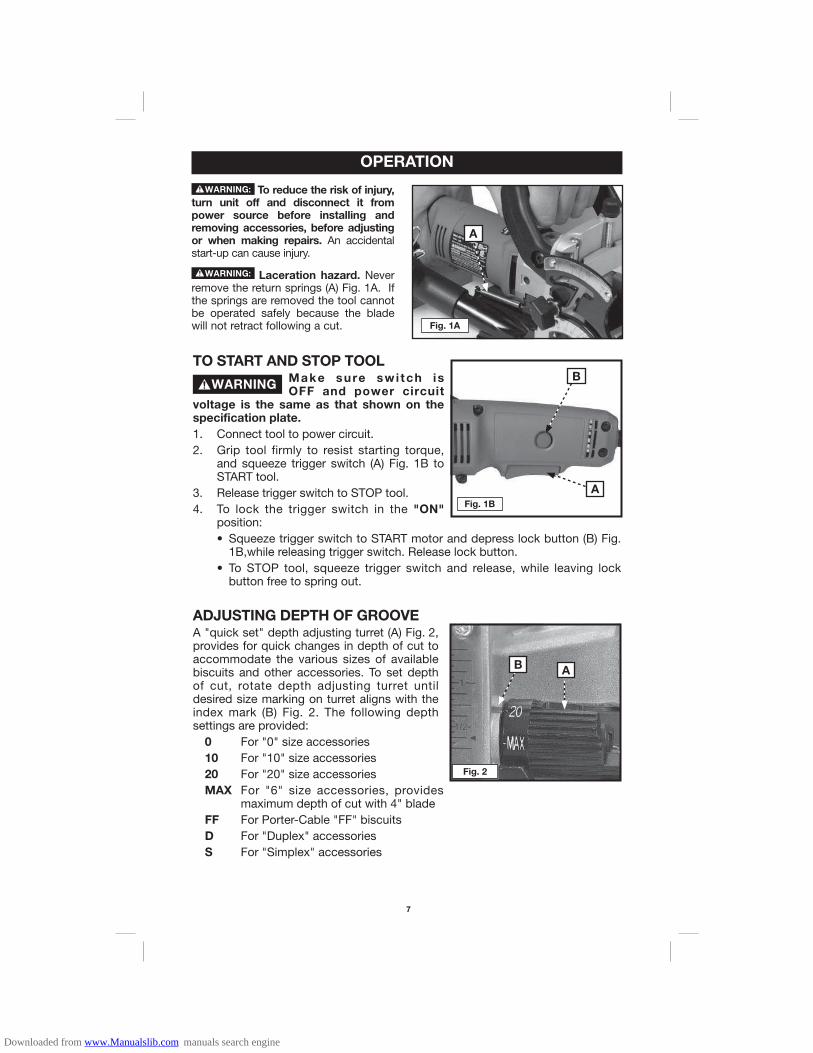
TO START AND STOP TOOLMake sure swi tch is OFF and power circuit
voltage is the same as that shown on the specification plate.
1. Connect tool to power circuit.2. Grip tool firmly to resist starting torque,
and squeeze trigger switch (A) Fig. 1B to START tool.
3. Release trigger switch to STOP tool.4. To lock the trigger switch in the "ON"
position:• Squeeze trigger switch to START motor and depress lock button (B) Fig.
1B,while releasing trigger switch. Release lock button.• To STOP tool, squeeze trigger switch and release, while leaving lock
button free to spring out.
ADJUSTING DEPTH OF GROOVEA "quick set" depth adjusting turret (A) Fig. 2, provides for quick changes in depth of cut to accommodate the various sizes of available biscuits and other accessories. To set depth of cut, rotate depth adjusting turret until desired size marking on turret aligns with the index mark (B) Fig. 2. The following depth settings are provided: 0 For "0" size accessories 10 For "10" size accessories 20 For "20" size accessories MAX For "6" size accessories, provides
maximum depth of cut with 4" blade FF For Porter-Cable "FF" biscuits D For "Duplex" accessories S For "Simplex" accessories
OPERATION
B
A
AB
Fig. 2
To reduce the risk of injury, turn unit off and disconnect it from power source before installing and removing accessories, before adjusting or when making repairs. An accidental start-up can cause injury.
Laceration hazard. Never remove the return springs (A) Fig. 1A. If the springs are removed the tool cannot be operated safely because the blade will not retract following a cut.
Fig. 1B
Fig. 1A
A
Downloaded from www.Manualslib.com manuals search engine

8
FINE ADJUSTMENTThe "quick set" depth adjustment is adjusted at the factory to produce joints with nominal clearance (biscuit to groove). A fine adjustment is provided allowing you to reduce or increase the clearance as desired. To adjust:1. Use an 7/16" wrench to loosen lock-nut
(A) Fig. 3.2. Rotate fine adjustment knob (B) Fig. 3, to
desired position (rotate knob clockwise to reduce depth of cut, rotate knob counter-clockwise to increase depth of cut).
3. While holding adjustment knob in desired position, tighten lock-nut firmly.
ADJUSTABLE FENCE
Model 557 is equipped with an integral, adjustable fence which:• provides micro-height adjustment. The distance scale includes indexes
to top of cut, to center of cut, and to bottom of cut.• tilts 0° through 135°, with an adjustable stop at 90°.• does not have to be removed to make "flush" cuts.
Height Adjustment (see Figs. 4 & 5)1. Loosen locking knob (A), and rotate knob (B) to position the fence as
desired, (rotate knob clockwise to raise fence, rotate knob counterclockwise to lower fence).
2. The depth scale (C), indicates the distance from the top edge of the workpiece to the blade: NOTE: The bottom line on scale (C) begins at 1/4" and all lines are in 1/16" increments.• The line across the center of the index block (D) indicates the distance to
the center of the blade.• The top edge of the index block (D) indicates the distance to the bottom
of the blade. • The bottom edge of the index block (D) indicates the distance to the top
of the blade.• The width of the index block (D) is equal to the thickness of the blade.
3. Once fence is in desired position, tighten knob (A).
AB
Fig. 3
A
B
Fig. 4 Fig. 5D
C
Downloaded from www.Manualslib.com manuals search engine

9
Angle Adjustment (see Figs. 6, 7, 8 & 9)1. Loosen locking knob (A).2. For angles between 0° and 90° - swing fence downward until desired angle
on lower scale (B), aligns with lower index mark (E). Tighten knob (A), to secure in place.
3. For angles between 90° and 135° - swing fence downward until the "gate" between the upper scale (D), and lower scale (B), aligns with locking knob. Swing scale arm down to align knob with upper scale. Move fence until desired angle on upper scale (D), aligns with upper index mark (C). Tighten knob (A), to secure in place.
0 degrees 60 degrees
FINE ADJUSTMENT (90° Position)
The adjustable 90° stop is factory adjusted for 90° and should not require additional adjustment. If "fine tuning" of the stop position is required: use a 5/64" hex wrench (not furnished), to rotate set-screw (F) Fig. 6. Rotate the set-screw clockwise to reduce the angle of the fence, rotate the set-screw counter-clockwise to increase the angle of the fence.
Fig. 6 Fig. 7
A
B
E
C
F
A
B
E
Fig. 8
90 degrees
D C
E
A
135 degrees
Fig. 9
DC
A
E
Downloaded from www.Manualslib.com manuals search engine

10
BLADES (2" and 4")
Model 557 is shipped with a 4" diameter blade installed. This blade is used for all operations except for the "FF" biscuit. To install the 2" blade for the "FF" biscuit:
Handle blades carefully. They are extremely sharp.
To reduce the risk of injury, turn unit off and disconnect it from power source before installing and removing accessories, before adjusting or when making repairs. An accidental start-up can cause injury.
1. Loosen four blade cover retaining screws (A) Fig. 10, and remove blade cover.
2. Depress and hold spindle lock button (B) Fig. 11 while rotating blade by hand until spindle lock engages.
3. Continue to hold spindle lock button while using the 5/32" hex wrench (furnished with tool), to remove blade retaining bolt and flange, (by rotating counter-clockwise).
4. Remove blade and store for future use.5. Place 2" diameter blade onto blade
mounting flange. Orient with teeth facing in same direction as directional arrow cast in housing (Fig. 14).
6. Position blade retaining flange (flat side out) to spindle, insert blade bolt, and rotate clockwise until hand-tight.
7. Depress and hold spindle lock button (B) Fig. 11, while rotating blade by hand until spindle lock engages.
8. Continue to hold spindle lock button while using the hex wrench (furnished with tool), to tighten blade retaining bolt securely, (by rotating clockwise).
9. Rotate the "quick set" depth adjusting turret (A) Fig. 12, to the "FF" position.
A
Fig. 13
A
Fig. 14
A
Fig. 12
Fig. 10
AB
Fig. 11
Downloaded from www.Manualslib.com manuals search engine
11
10. Lift safety lever (A) Fig. 13, fully retract the plunge mechanism, and reposition the safety lever as shown in Fig. 14. Slowly release pressure on plunge mechanism.
11. Reposition blade cover plate to tool, and secure in place with the four retaining screws (removed in step 1).
Do not operate tool without blade cover installed.
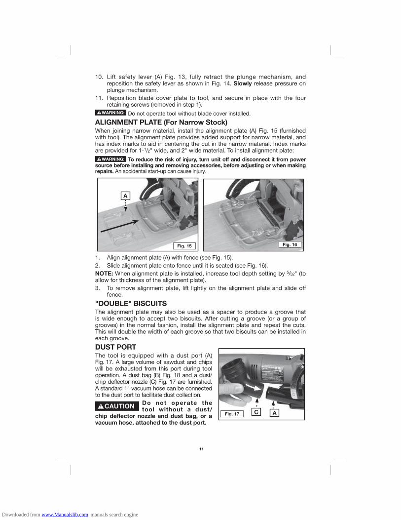
ALIGNMENT PLATE (For Narrow Stock)When joining narrow material, install the alignment plate (A) Fig. 15 (furnished with tool). The alignment plate provides added support for narrow material, and has index marks to aid in centering the cut in the narrow material. Index marks are provided for 1-1/2" wide, and 2" wide material. To install alignment plate:
To reduce the risk of injury, turn unit off and disconnect it from power source before installing and removing accessories, before adjusting or when making repairs. An accidental start-up can cause injury.
Fig. 16Fig. 15
A
1. Align alignment plate (A) with fence (see Fig. 15).2. Slide alignment plate onto fence until it is seated (see Fig. 16).NOTE: When alignment plate is installed, increase tool depth setting by 5/32" (to allow for thickness of the alignment plate).3. To remove alignment plate, lift lightly on the alignment plate and slide off
fence.
"DOUBLE" BISCUITSThe alignment plate may also be used as a spacer to produce a groove that is wide enough to accept two biscuits. After cutting a groove (or a group of grooves) in the normal fashion, install the alignment plate and repeat the cuts. This will double the width of each groove so that two biscuits can be installed in each groove.
DUST PORTThe tool is equipped with a dust port (A) Fig. 17. A large volume of sawdust and chips will be exhausted from this port during tool operation. A dust bag (B) Fig. 18 and a dust/chip deflector nozzle (C) Fig. 17 are furnished. A standard 1" vacuum hose can be connected to the dust port to facilitate dust collection.
Do not operate the tool without a dust/
chip deflector nozzle and dust bag, or a vacuum hose, attached to the dust port.
Fig. 17 C A
Downloaded from www.Manualslib.com manuals search engine
12
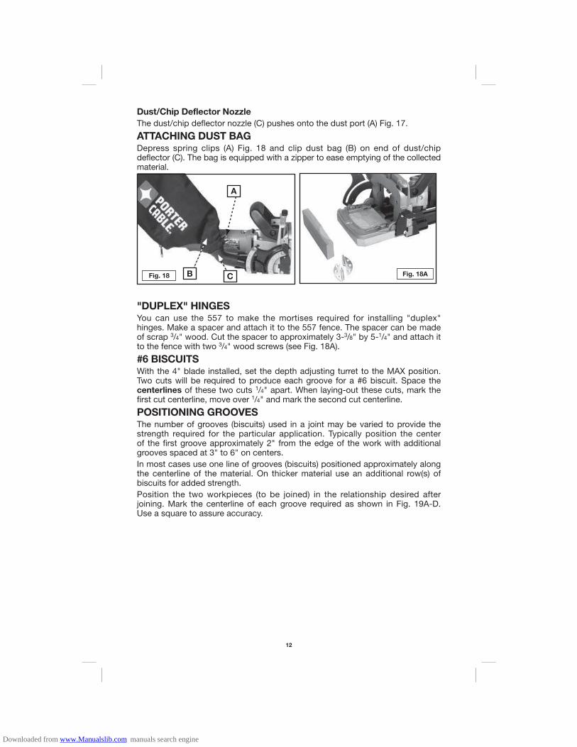
Dust/Chip Deflector Nozzle
The dust/chip deflector nozzle (C) pushes onto the dust port (A) Fig. 17.
ATTACHING DUST BAGDepress spring clips (A) Fig. 18 and clip dust bag (B) on end of dust/chip deflector (C). The bag is equipped with a zipper to ease emptying of the collected material.
Fig. 18
A
B C Fig. 18A
"DUPLEX" HINGESYou can use the 557 to make the mortises required for installing "duplex" hinges. Make a spacer and attach it to the 557 fence. The spacer can be made of scrap 3/4" wood. Cut the spacer to approximately 3-3/8" by 5-1/4" and attach it to the fence with two 3/4" wood screws (see Fig. 18A).
#6 BISCUITSWith the 4" blade installed, set the depth adjusting turret to the MAX position. Two cuts will be required to produce each groove for a #6 biscuit. Space the centerlines of these two cuts 1/4" apart. When laying-out these cuts, mark the first cut centerline, move over 1/4" and mark the second cut centerline.
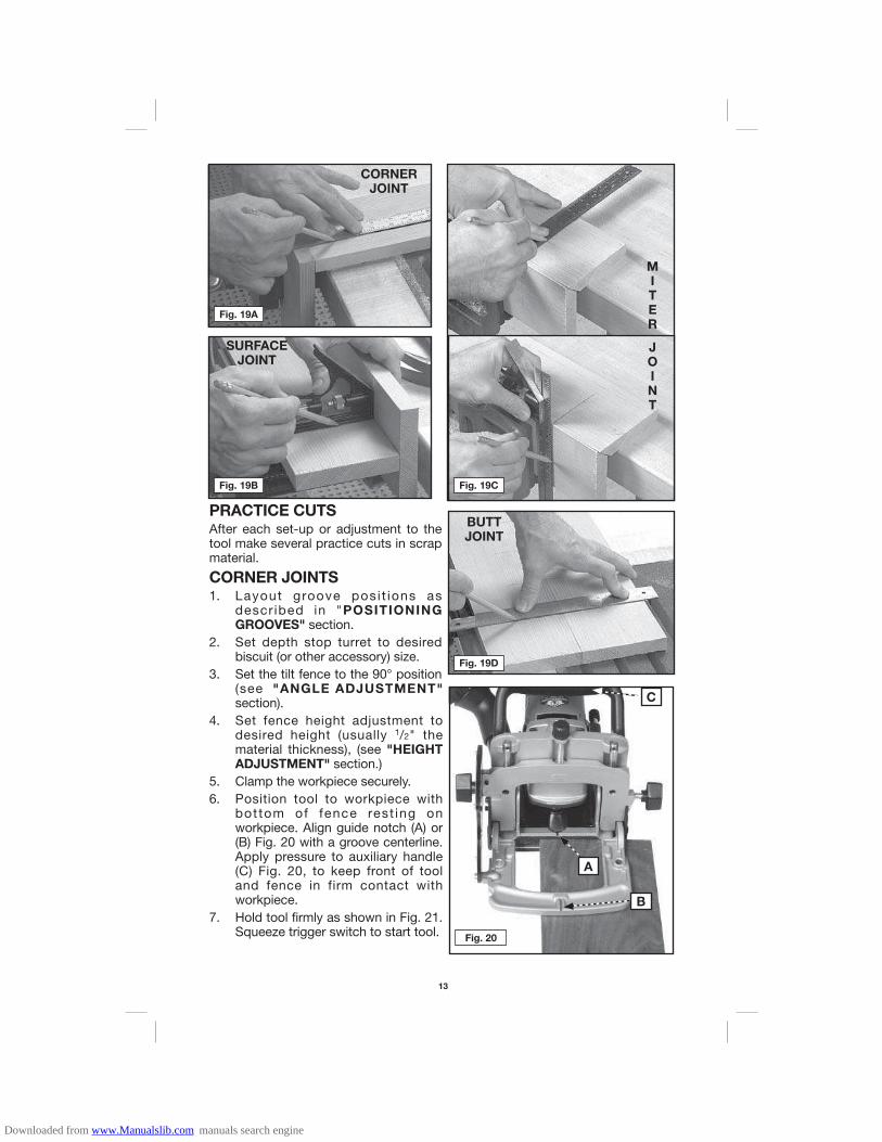
POSITIONING GROOVESThe number of grooves (biscuits) used in a joint may be varied to provide the strength required for the particular application. Typically position the center of the first groove approximately 2" from the edge of the work with additional grooves spaced at 3" to 6" on centers.In most cases use one line of grooves (biscuits) positioned approximately along the centerline of the material. On thicker material use an additional row(s) of biscuits for added strength.Position the two workpieces (to be joined) in the relationship desired after joining. Mark the centerline of each groove required as shown in Fig. 19A-D. Use a square to assure accuracy.
Downloaded from www.Manualslib.com manuals search engine
13
PRACTICE CUTSAfter each set-up or adjustment to the tool make several practice cuts in scrap material.
CORNER JOINTS1. Layout groove posi t ions as
descr ibed in "POSITIONING GROOVES" section.
2. Set depth stop turret to desired biscuit (or other accessory) size.
3. Set the tilt fence to the 90° position (see "ANGLE ADJUSTMENT" section).
4. Set fence height adjustment to desired height (usually 1/2" the material thickness), (see "HEIGHT ADJUSTMENT" section.)
5. Clamp the workpiece securely.6. Position tool to workpiece with
bottom of fence rest ing on workpiece. Align guide notch (A) or (B) Fig. 20 with a groove centerline. Apply pressure to auxiliary handle (C) Fig. 20, to keep front of tool and fence in firm contact with workpiece.
7. Hold tool firmly as shown in Fig. 21. Squeeze trigger switch to start tool.
MITER
JOINT
BUTTJOINT
Fig. 19D
CORNERJOINT
Fig. 19A
SURFACEJOINT
Fig. 19B Fig. 19C
Fig. 20
C
A
B
Downloaded from www.Manualslib.com manuals search engine

14
8. At a slow, steady pace, push tool forward in base as far as depth stop allows.
9. Release trigger switch to stop tool and remove tool from work.
10. Repeat steps 6 through 9 until all the grooves for this joint are completed.
NOTE: Assemble all joints and verify alignments before applying glue (see Fig. 22).
SURFACE ("T") JOINTS1. Layout groove positions as described in "POSITIONING GROOVES" section.2. Set depth stop turret to desired biscuit (or other accessory), size.3. Mark centerline of joint on workpiece (A) (see Fig. 23).
4. Clamp a straight edge guide to the workpiece 3/8" back from the joint centerline (as marked in Step 2). Clamp workpiece securely (see Fig. 24).
5. Set tilt fence to 0° position (see "ANGLE ADJUSTMENT SECTION" section).6. Position tool to workpiece with bottom of base against straight edge and
guide notch (C) Fig. 25, aligned with a groove centerline. Apply pressure to auxiliary handle (D) Fig. 25 to hold tool firmly in place.
7. Hold tool firmly as shown in Fig. 21. Squeeze trigger switch to start tool.8. At a slow, steady pace, push tool forward in base as far as depth stop allows.9. Release trigger switch to stop tool and remove tool from work.10. Repeat steps 5 through 8 until all the grooves in workpiece (A) are completed.11. Follow steps 3 through 10 of "CORNER JOINTS" section to complete
required grooves in workpiece (B) Fig. 23.
Fig. 23
A
B
Fig. 22
Fig. 24
3/8"
Fig. 21
Downloaded from www.Manualslib.com manuals search engine

15
NOTE: Assemble all joints and verify alignments before applying glue (see Fig. 26).
BUTT JOINTSTool adjustment and operation for producing butt joints (see Fig. 19) are the same as for "CORNER JOINTS".
MITER JOINTS1. Layout groove posit ions as
described in "POSITIONING GROOVES" section.
2. Set depth stop turret to desired biscuit (or other accessory) size.
3. Set the tilt fence to desired angle (see "ANGLE ADJUSTMENT" section).
4. Set fence height adjustment to desired height (see "HEIGHT ADJUSTMENT" section).
5. Clamp workpiece securely.6. Position tool to workpiece utilizing
either guide notch (A) or (B) Fig. 27, to align tool with a groove centerline. Apply pressure to auxiliary handle (C) Fig. 27, to hold tool firmly in place.
7. Hold tool firmly as shown in Fig. 28, and squeeze trigger switch to start tool.8. At a slow, steady pace, push tool forward in base as far as depth stop allows.9. Release trigger switch to stop tool and remove tool from work.10. Repeat Steps 6 through 8 until all the grooves for this joint are completed.NOTE: Assemble all joints and verify alignments before applying glue (see Fig. 29).
Fig. 25
D
C
Fig. 26
Fig. 28 Fig. 29
Fig. 27
C
A
B
Downloaded from www.Manualslib.com manuals search engine

16
For assistance with your tool, visit our website at www.deltaportercable.com for a list of service centers, or call the Porter-Cable Customer Care Center at (888) 848-5175.
TROUBLESHOOTING
To reduce the risk of injury, turn unit off and disconnect it from power source before installing and removing accessories, before adjusting or when making repairs. An accidental start-up can cause injury.
ALWAYS USE SAFETY GLASSES. Everyday eyeglasses are NOT safety glasses. Also use face or dust mask if cutting operation is dusty. ALWAYS wear certified safety equipment:
• ANSI Z87.1 eye protection (CAN/CSA Z94.3) • ANSI S12.6 (S3.19) hearing protection • NIOSH/OSHA/MSHA respiratory protection.
REPAIRSFor assistance with your tool, visit our website at www.deltaportercable.com for a list of service centers, or call the Porter-Cable Customer Care Center at (888) 848-5175.
CLEANING
Periodically blowing dust and chips out of the motor housing using clean, dry compressed air is a suggested maintenance procedure. To reduce the risk of serious per-sonal injury, ALWAYS wear ANSI Z87.1 safety glasses while using compressed air.
When cleaning, use only mild soap and a damp cloth on plastic parts. Many household cleaners contain chemicals which could seriously damage plastic. Also, do not use gasoline, turpentine, lacquer, paint thinner, dry cleaning fluids or similar products which may seriously damage plastic parts. NEVER let any liquid get inside the tool; NEVER immerse any part of the tool into a liquid.
FAILURE TO STARTShould your tool fail to start, check to make sure the prongs on the cord plug are making good contact in the outlet. Also, check for blown fuses or open circuit breakers in the line.
LUBRICATIONThis tool has been lubricated with a sufficient amount of high grade lubricant for the life of the unit under normal operating conditions. No further lubrication is necessary.
BRUSH INSPECTION
For your continued safety and electrical protection, brush inspection and replacement on this tool should ONLY be performed by a PORTER-CABLE FACTORY SERVICE CENTER OR PORTER-CABLE AUTHORIZED WARRANTY SERVICE CENTER.At approximately 100 hours of use, take or send your tool to your nearest Porter-Cable Factory Service center or Porter-Cable Authorized Warranty Service Center to be thoroughly cleaned and inspected. Have worn parts replaced and lubricated with fresh lubricant. Have new brushes installed, and test the tool for performance.Any loss of power before the above maintenance check may indicate the need for imme-diate servicing of your tool. DO NOT CONTINUE TO OPERATE TOOL UNDER THIS CONDITION. If proper operating voltage is present, return your tool to the service station for immediate service.
MAINTENANCE
Downloaded from www.Manualslib.com manuals search engine

17
Since accessories, other than those offered by Porter-Cable, have not been tested with this product, use of such accessories with this tool could be hazardous. To reduce the risk of injury, only Porter-Cable recommended accessories should be used with this product.
A complete line of accessories is available from your Porter-Cable Factory Service Center or a Porter-Cable Authorized Warranty Service Center. Please visit our Web Site www.delta-portercable.com for a catalog or for the name of your nearest supplier.
ACCESSORIES
REPLACEMENT PARTSUse only identical replacement parts. For a parts list or to order parts, visit our service website at www.deltaportercableservicenet.com. You can also order parts from your nearest Porter-Cable Factory Service Center or Porter-Cable Authorized Warranty Service Center. Or, you can call our Customer Care Center at (888) 848-5175.
SERVICE AND REPAIRSAll quality tools will eventually require servicing and/or replacement of parts. For information about Porter-Cable, its factory service centers or authorized warranty service centers, visit our website at www.deltaportercable.com or call our Customer Care Center at (888) 848-5175. All repairs made by our service centers are fully guaranteed against defective material and workmanship. We cannot guarantee repairs made or attempted by others.You can also write to us for information at PORTER-CABLE, 4825 Highway 45 North, Jackson, Tennessee 38305 - Attention: Product Service. Be sure to include all of the infor-mation shown on the nameplate of your tool (model number, type, serial number, etc.).
SERVICE
THREE YEAR LIMITED WARRANTY
PORTER-CABLE will repair, without charge, any defects due to faulty materials or work-manship for three years from the date of purchase. This warranty does not cover part failure due to normal wear or tool abuse. For further detail of warranty coverage and warranty repair information, visit www.deltaportercable.com or call (888) 848-5175. This warranty does not apply to accessories or damage caused where repairs have been made or attempted by others. This warranty gives you specific legal rights and you may have other rights which vary in certain states or provinces.In addition to the warranty, PORTER-CABLE tools are covered by our:1 YEAR FREE SERVICE: PORTER-CABLE will maintain the tool and replace worn parts caused by normal use, for free, any time during the first year after purchase.90 DAY MONEY BACK GUARANTEE: If you are not completely satisfied with the perfor-mance of your PORTER-CABLE Power Tool, Laser, or Nailer for any reason, you can return it within 90 days from the date of purchase with a receipt for a full refund – no questions asked.LATIN AMERICA: This warranty does not apply to products sold in Latin America. For products sold in Latin America, see country specific warranty information contained in the packaging, call the local company or see website for warranty information.To register your tool for warranty service visit our website at www.deltaportercable.com.
Downloaded from www.Manualslib.com manuals search engine

18
WARNING LABEL REPLACEMENTIf your warning labels become illegible or are missing, call (888) 848-5175 for a free replace-ment.
PATENT NOTIFICATIONManufactured under one or more of the following U.S. patents:6,896,0166,422,2756,612,3496,006,802Other patents pending.
Downloaded from www.Manualslib.com manuals search engine