plate-fin heat exchangers guide to their specification and use (1).pdf
DESCRIPTION
Brazed plate fin HETRANSCRIPT

PLATE-FIN HEAT EXCHANGERS
GUIDE TO THEIR SPECIFICATION AND USE
1st Edition 1987 Amended - October 1990
Editor: M.A. Taylor Process Engineering Consultant
58, Longfield Drive Amersham, Bucks. HP6 5HE
England
Published by HTFS ®, (Harwell Laboratory, Oxon OX11 ORA, United Kingdom) for the Plate-Fin Study Group ®HTFS is a registered trademark

FOREWORD
This Guide was produced by the PFHE Guide Committee of the Plate-Fin Study Group associated with the Heat Transfer and Fluid Flow Service (HTFS). The Plate-Fin Study Group members currently are: Air Products Ltd Hersham Place Molesey Road Walton on Thames Surrey KT12 4RZ
Shell (UK) Exploration & Production Shell Mex House Strand London WC2R ODX
BP International Ltd Britannic House Moor Lane London EC2Y 9BU
Shell Internationale Petroleum Maatschappij Carel van Bylandtlaan 23 Postbus 162 2501 AN Den Haag Netherlands
British Gas plc 326 High Holborn London WC1B 7PT
Statoil Klaebuveien 194 7000 Trondheim Norway
Norsk Hydro Veritasveien 1 N. 1322 Hovik Norway
- i -

ACKNOWLEDGEMENTS
The PFHE Guide Committee wish to record their thanks to the following Companies and Organisations for their help in the preparation of this Plate-Fin Heat Exchanger Guide. Air Products Limited Hersham Place Molesey Road Walton on Thames Surrey KT12 4RX UK 0932 249200
Mike Taylor Process Engineering Consultant 58 Longfield Drive Amersham Bucks HP6 5HE UK 04947 26299
BOC Cryoplants Limited Engineering Centre 30 Priestley Road Guildford Surrey GU2 9BU UK 0483 300900
Marston Palmer Limited Wobaston Road Fordhouses Wolverhampton WV10 6QJ UK 0902 783361
BP International Limited Britannic House Moor Lane London EC2Y 9BU UK 01 920 8000
Stone and Webster Engineering Limited Stone and Webster House 500 Elder Gate Central Milton Keynes MK9 1BA UK 0908 668844
British Gas plc 326 High Holborn London WC1B 7PT UK 01 242 0789
Shell (UK) Exploration and Production Shell Mex House Strand London WC2R 0DX UK 01 257 4000
Costain Petrocarbon Limited MIOC Styal Road Wythenshawe Manchester M22 5WB UK 061 436 8000
Sulzer (UK) Limited Blackwater Way Aldershot Hampshire GU12 4DR UK 0252331351
Heat Transfer and Fluid Flow Service Building 392.7 Harwell Laboratory Oxon OX11 ORA UK 0235 24141
The PFHE Guide Committee also acknowledges the help and advice received from many colleagues in industry.
- ii -

- iii -
COMMITTEE MEMBERSHIP
Mr R. Allam Air Products Limited
Mr P. Brice BP International Limited
Dr S. Bruzzi Sulzer (UK) Limited
Mr P. Clarke Sulzer (UK) Limited
Mr R. Clarke HTFS, Harwell
Mr M. Collyer Air Products Limited
Mr P. Drew Shell (UK) Exploration and Production
Mr D. Edge Stone and Webster Engineering Limited
Ms H. Edwards British Gas plc
Mr G. Elmore Air Products Limited
Mr J. Felton Marston Palmer Limited
Mr E. Gregory Marston Palmer Limited
Mr D. Limb Costain Petrocarbon Limited
Mr R. McFarlane BP International Limited
Mr W. Meinardi BOC Cryoplants Limited
Mr J.M. Robertson HTFS, Harwell
Mr M.A. Taylor (Editor) Consultant

PREFACE
This Guide describes the Plate-Fin Heat Exchanger (PFHE), its applications, design, manufacture, testing, installation, operation and maintenance.
The methods and practices defined by this Guide may form the basis of an agreement
between Purchaser and Manufacturer, at their discretion. Based on this Guide, the Plate-Fin Heat Exchanger Guide Committee intends to develop a
Code of Practice for the Specification, Manufacture and Use of Plate-Fin Heat Exchangers at a later date.
WARRANTY
The procedures and advice herein are recommended by the Plate-Fin Exchanger Guide Committee, to assist users, engineers and designers who specify, design, manufacture, install and use plate-fin heat exchangers. The Guide is based on the best available research and field experience in the design, manufacture, installation and use of plate-fin heat exchangers.
This Guide may be subject to revision as further investigation or experience shows necessary
or desirable. Nothing herein shall constitute a warranty of any kind, expressed or implied, and warranty responsibility of any kind is expressly denied.
COPYRIGHT
The copyright of this document is vested in Harwell on behalf of the Plate-Fin Study Group of the Heat Transfer and Fluid Flow Service (HTFS) of Harwell. Reproduction without permission is expressly forbidden.
®Copyright 1987 HTFS
Harwell Laboratory Oxon
OX11 0RA
- 4 -

- 5 -
GUIDE LAYOUT AND HOW TO USE
The Guide is set out in the order that “things are done”. For example, before a plate-fin heat exchanger can be designed, the Purchaser must supply the Manufacturer with a process specification. Similarly the hardware cannot be fabricated until the process and mechanical designs are both complete.
The Guide is broken into five parts:
I. Introduction
II. Description
III. Process Design
IV. Mechanical Design
V. Hardware
Each part is further divided into sub-sections. Thus, for example, once familiar with the plate-fin heat exchanger in general, the experienced process designer need only refer to Part III “Process Design”.
It is the intention of the Plate-Fin Study Group that further editions of the Guide will be published as significant new developments take place in PFHE technology. The PFHE Guide Committee would therefore welcome any comments or corrections from readers for incorporation into such future editions.

PART I INTRODUCTION AND CONTRACTURAL
MATTERS

1.0 THE PLATE-FIN HEAT EXCHANGER
1.1 ESSENTIAL FEATURES Plate-fin heat exchangers (PFHEs) are a form of compact heat exchanger consisting of a stack of alternate flat plates called “parting sheets” and corrugations, brazed together as a block. Streams exchange heat by flowing along the passages made by the corrugations between the parting sheets. The corrugations serve both as secondary heat transfer surface and mechanical support for the internal pressures between layers. Construction details are given in Section 4.0.
1.2 APPLICATIONS PFHEs are used principally for their advantages over other forms of heat exchanger which are as follows:
• very close temperature approaches and high thermal effectiveness,
• large heat transfer surface per unit volume (1000 m2/m3 typical),
• low weight per unit heat transfer,
• possibility of heat exchange between many process streams.
The PFHE can achieve temperature approaches as low as 1°C between single phase streams and 3°C between multi-phase streams. Typically, overall mean temperature differences of 3 to 6°C are employed in aluminium PFHE applications. Up to ten process streams can be combined into a single PFHE.
Provided the streams are reasonably clean, PFHEs can be used to exchange heat in most processes, for a wide range of stream compositions and pressure/temperature envelopes.
Current areas of application include:
• cryogenics
• petro-chemical production
• syngas production
• aero-space
• land transport (automotive, locomotive)
• oil and gas processing.
PFHEs are used in all modes of heat duty; including:
• heat exchange between gases, liquids or both
• condensing, including partial and reflux condensing
• boiling
• sublimation (“reversing” heat exchangers)
• heat or cold storage
Fluids handled to date include:
air, nitrogen, oxygen, argon, helium, carbon dioxide, carbon monoxide, natural gas, hydrogen, methane, ethane, propane, butane, ethylene, propylene, xylene, acetone, uranium hexafluoride, steam, water, refrigerants, fuel gas, refinery off-gas, aviation oils and fuels.
- 1.1 -

Provided correct materials are selected, the PFHE can be specified for temperatures ranging from near absolute zero to more than 800 °C and for pressures up to at least 90 bar.
1.3 ECONOMICS The PFHE is not necessarily cheaper for a given duty than other forms of heat transfer equipment because the method used for constructing PFHEs is complex. The PFHE is also limited in application to relatively clean streams because of its small flow passages; blockage may arise from solids carried by the process stream or by precipitation or scaling within the block. Upstream strainers should be employed where there is any doubt about solids in the feed. Freezing can also take place, but this is a problem common to all heat exchangers in such service.
Compared with a conventional shell and tube heat exchanger made in carbon steel, an aluminium PFHE designed for typically 70 bar pressure would show the following advantages:
• about 1000m2 heat transfer surface per cubic metre volume compared with around 300 m2/m3,
• one third the equipment weight for a given volume,
• significantly better heat transfer per surface. These advantages in combination give the PFHE about 25 times more surface per equipment weight than the shell and tube heat exchanger.
Further benefits occur with "long" thermal duties, where the overall mean temperature difference is small compared with the temperature range of the streams. The PFHE can operate in true counter-flow, unlike the shell and tube heat exchanger whose shellside flow is usually a mixture of cross-flow and counter-flow, and which therefore has to employ additional surface or further shells in series to overcome this non-ideality.
Additional benefits result from the reduction in plot area, foundations, support and insulation required.
1.4 MATERIALS Plate-fin heat exchangers can be made in a variety of materials. Aluminium is preferred for cryogenic duties, on account of its relatively high conductivity, strength at low temperatures and low cost. Volume production for cryogenic duties has allowed manufacturers to invest in large aluminium brazing furnaces.
Above ambient temperature, most aluminium alloys rapidly lose their strength. Stainless steels, nickel alloys and copper alloys are used for temperatures up to 500°C but, to date, the higher temperature applications have been limited to small units. Some Manufacturers are able to supply PFHEs outside these ranges for special orders, e.g. in stainless steel.
1.5 SIZE Maximum size is limited not only by the brazing furnace dimensions but also by the furnace lifting capacity. The higher pressure PFHEs having thicker fins and parting sheets are heavier; there is therefore a correlation between design pressure and maximum block size. The heating characteristics of denser blocks also impose limitations on the maximum size which can be brazed.
Manufacturers each have their own size limits, but typical maximum dimensions for low pressure aluminium PFHEs are 1.2 m x 1.2 m in cross-section x 6.2m along the direction of flow, and 1.0 m x 1.0 m x 1.5 m respectively for non-aluminium; higher pressure units being
- 1.2 -

heavier per volume, make both handling and brazing more difficult, thus reducing the economic maximum size. For a design pressure of 50 bar, the maximum block size in aluminium would be typically 0.9 m x 1.0 m x 6.2 m.
Dimensions greater than these can sometimes be accommodated by arrangement with the Manufacturer, but more often duties which call for larger units are met by welding together several blocks, or by manifolding pipework.
2.0 RESPONSIBILITIES OF PURCHASER AND MANUFACTURER A purchase contract for a PFHE must at the outset define the responsibilities of both the Purchaser and the Manufacturer. The following is a typical example which could be used by agreement between the parties before the contract was signed.
2.1 PURCHASER The Purchaser is responsible for providing the Manufacturer with a specification which details the performance required of the PFHE, including any special requirements. The Purchaser is also responsible for supplying the Manufacturer with all the process stream and operating data required to enable the Manufacturer to guarantee the performance and integrity of the PFHE. See Section 3.0.
Purchasers with sufficient thermal rating experience may choose to carry out the thermal design of the PFHE. It is then only necessary for the Purchaser to supply sufficient data to enable the Manufacturer to guarantee the integrity of the mechanical design of the PFHE.
2.2 MANUFACTURER The Manufacturer guarantees that the exchanger will perform in accordance with the Purchaser's specification, when it is operated in accordance with the conditions specified by the Purchaser.
The Manufacturer is responsible for the mechanical design and for the thermal design where this latter is not specified by the Purchaser.
Inspection and approval by the Independent Inspection Authority or any other body does not relieve the Manufacturer of the responsibility for the quality of construction of the PFHE.
When this Guide forms part of the purchase agreement the Manufacturer is required to supply the following information for the Purchaser's approval:
(a) a completed plate-fin heat exchanger specification sheet,
(b) fully dimensioned general arrangement and detail drawings of the exchanger,
(c) a list of the allowable forces and moments which may be imposed on the exchanger nozzles,
(d) a list of materials used in the construction of the exchanger, together with material certificates,
(e) the welding procedures, specifications and qualifications, and welders' qualifications,
(f) records of any repairs carried out on the exchanger during manufacture,
(g) records of any non-destructive tests carried out,
(h) all reports of hydrostatic, leak detection, flow and pressure drop tests carried out on the exchanger,
- 1.3 -

(i) a Manufacturer's Data Report if PFHE designed to ASME, or equivalent Data Report if not.
The Purchaser will require delivery of the plate-fin heat exchanger, packaged for shipping, stubs or flanges blanked, and pressure-sealed with dry nitrogen.
2.3 USE OF GUIDE IN PROCUREMENT The Guide is not a mandatory document and as such does not use the imperative, except as an example. The Guide, or parts of it, can, by agreement between Purchaser and Manufacturer, be used as a mandatory document. The following definitions of third person verb use might then be helpful:
(a) 'Will' describes actions, facts, etc, and is non-mandatory.
(b) 'May' is used where alternatives are equally preferable.
(c) 'Should' is used where a provision is preferred.
(d) 'Shall' is used where a provision is mandatory.
(e) 'Must' is used only where a provision is a statutory requirement.
3.0 PFHE DATA SHEETS The Design Data Sheet and Process Data Sheet shown overleaf are used to transmit information between Purchaser and Manufacturer/Designer and also serve as a record summary for both parties.
The Purchaser should complete items 1 through 20 on the top part of the Design Data Sheet, (except the number of blocks in series or in parallel per train which will be completed by the Manufacturer/Designer). Note that each stream can have an independent design pressure and temperature. The Manufacturer/Designer will return the Design Data Sheet with the remaining particulars completed.
The Purchaser must specify all applicable phase properties. One Process Data Sheet is used for each stream.
The Purchaser must also supply a heat release curve for any stream that does not exhibit linear temperature/heat release; this can be done on the Process Data Sheet, or with a computer output sheet.
If any alternative design cases have to be met by the PFHE, for example turndown conditions, off-design conditions, pressure or thermal cycling or any other special operating conditions, the Purchaser must specify sufficient details for these to be included in the Manufacturer's performance guarantee.
If known, the Purchaser should specify sizes, type and orientation of connections and define any specific exchanger support and packing requirements.
The boundary between Purchaser's and Manufacturer's data is not precise and depends on the Purchaser's level of knowledge of PFHEs. In many cases the Purchaser will have specialist knowledge of PFHE design and performance, based on extensive experience and may then specify the PFHE in detail. In such cases, where the standard specification sheets are inadequate, the Purchaser should include additional data sheets, for example to show the layer stacking order, the individual layer arrangements, the overall exchanger configuration, etc.
- 1.4 -

- 1.5 -

- 1.6 - - 1.6 -

PART II
DESCRIPTION

4.0 DESCRIPTION OF THE PFHE COMPONENTS
4.1 INTRODUCTION This Section uses terminology commonly accepted in the UK PFHE manufacturing industry. Equivalent terminology used elsewhere is defined in the Glossary, Appendix A.
A PFHE consists of a block (“matrix” or “core”) of alternating layers of corrugated fins and flat separators known as parting sheets. See Figure 4.1.
Each corrugated layer forms a flow channel between the parting sheets. The edges of each layer are sealed by edge-bars. Corrugations and edge-bars are brazed to the parting sheets on either side to form a rigid pressure-containing void. The first and last sheets, called cap sheets, are usually of thicker material than the parting sheets to give protection against physical damage.
Each stream enters the block from its own header, via ports in the edge-bars of selected layers, and leaves in a similar fashion. The header tanks are welded to the edge-bars and parting sheets across the full stack of layers.
Brazing must be carried out in the absence of oxides or impurities; two methods are in common use.
Salt bath brazing uses molten salt to remove the tenacious aluminium oxide layer and grease, etc, which would otherwise weaken the braze. Brazing takes place in the same bath when the temperature is raised above the melting point of the brazing alloy. The brazed block has to be cleansed of the residual solidified salt from the bath, and then thoroughly dried.
Brazing in a vacuum furnace produces a clean, dry product, but requires a far greater degree of cleanliness of the work before brazing starts.
Many metals besides aluminium can be vacuum brazed, but salt bath brazing is restricted to aluminium only.
The dimensions of the heat exchanger are normally given in the following order (see Figure 4.1):
Width (W) x Stack Height (H) x Length (L).
Note that the terms “width”, “height” and “length” refer to the PFHEs orientation when it is brazed. In operation it is likely that the PFHE will be mounted so that the streams flow up or down the “length”. The “width” and “height” of the block always define the plane of the flow cross-section irrespective of the orientation of the PFHE.
The number of layers, fin types, layer stacking arrangements and process stream circuitry are optimised to suit one of several variables, which in turn depend on the application. For example, the aircraft industry would minimise weight and space, the process industry might minimise capital cost, or heat transfer for a given pumping power.
- 2.1 -

Figure 4.1: General View of One End of a 3-Stream Plate-Fin Heat Exchanger (courtesy HTFS)
4.2 CONSTRUCTION Figure 4.1 illustrates a PFHE designed for three streams. Process stream (1) enters through a nozzle and header tank at the base of the block (not shown). The stream passes through gaps in the edge-bars into selected layers of the block, 2, 5, 8, etc, in this case. The process stream leaves the block through gaps in the edge-bars and then through the outlet header tank and nozzle on the top of the block as shown in Figure 4.1.
Process stream (2) enters and leaves in a similar way to process stream (1) but in reverse direction through layers 1, 4, 7, etc.
Process stream (3) flows in the same direction as process stream (1) through layers 3, 6, 9, etc, but its header tanks are mounted on the sides of the block rather than the ends.
Internal distributors composed of sloping finned passages (Figure 4.1) conduct the streams from the narrow entry ports across the full width of the heat transfer finning, and similarly back into the exit ports.
The header tanks are fabricated from half cylinders with welded end closures. For high pressure duties the end closures are specially formed, often into a “petal” shape. Nozzles are welded into profiled holes cut in the cylindrical section.
Parting sheet thicknesses are defined by mechanical requirements and range typically from 0.5 to 2.0 mm; vacuum brazing tends to require thicker sheets than salt bath brazing to permit
- 2.2 -

good heat diffusion. Cap sheets (the outermost sheets) are used chiefly for protection and are therefore thicker than parting sheets, typically 6 mm. Edge-bars typically vary in width from 3 to 25 mm; their thickness is the same as the fin height.
Standard fin heights come in two ranges: 3.81, 5.1, 6.35, 8.89, and 11.8 mm, or 5.1, 7.1 and 9.53 mm. Many Manufacturers can supply both ranges and also non-standard dimensions.
4.3 FLOW ARRANGEMENTS Counter-flow, Figures 4.3 and 4.4 (b), is the most thermally effective. If high effectiveness is not required, or if either or both streams are nearly isothermal (as in single component condensing or boiling), the cheaper cross-flow arrangement, Figures 4.2 and 4.4 (a), may be preferred. Cross-counter-flow, Figure 4.4 (c), approaches true counter-flow whilst avoiding the more expensive distributor arrangements necessary for counter-flow; a small degree of temperature cross can be tolerated, i.e. the outlet temperature of the hot stream or streams may be a few degrees lower than the outlet temperature of the cold stream or streams.
Table 4/1 summarises the features of each arrangement.
Figure 4.2: Cross-Flow (courtesy Marston Palmer Ltd)
Figure 4.3: Counter-Flow (courtesy Marston Palmer Ltd)
- 2.3 -
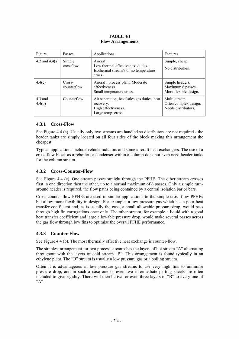
TABLE 4/1 Flow Arrangements
Figure Passes Applications Features
4.2 and 4.4(a) Simple crossflow
Aircraft. Low thermal effectiveness duties. Isothermal stream/s or no temperature cross.
Simple, cheap.
No distributors.
4.4(c) Cross-counterflow
Aircraft, process plant. Moderate effectiveness. Small temperature cross.
Simple headers. Maximum 6 passes. More flexible design.
4.3 and 4.4(b)
Counterflow Air separation, feed/sales gas duties, heat recovery. High effectiveness. Large temp. cross.
Multi-stream. Often complex design. Needs distributors.
4.3.1 Cross-Flow See Figure 4.4 (a). Usually only two streams are handled so distributors are not required - the header tanks are simply located on all four sides of the block making this arrangement the cheapest.
Typical applications include vehicle radiators and some aircraft heat exchangers. The use of a cross-flow block as a reboiler or condenser within a column does not even need header tanks for the column stream.
4.3.2 Cross-Counter-Flow See Figure 4.4 (c). One stream passes straight through the PFHE. The other stream crosses first in one direction then the other, up to a normal maximum of 6 passes. Only a simple turn-around header is required, the flow paths being contained by a central isolation bar or bars.
Cross-counter-flow PFHEs are used in similar applications to the simple cross-flow PFHEs but allow more flexibility in design. For example, a low pressure gas which has a poor heat transfer coefficient and, as is usually the case, a small allowable pressure drop, would pass through high fin corrugations once only. The other stream, for example a liquid with a good heat transfer coefficient and large allowable pressure drop, would make several passes across the gas flow through low fins to optimise the overall PFHE performance.
4.3.3 Counter-Flow See Figure 4.4 (b). The most thermally effective heat exchange is counter-flow.
The simplest arrangement for two process streams has the layers of hot stream “A” alternating throughout with the layers of cold stream “B”. This arrangement is found typically in an ethylene plant. The “B” stream is usually a low pressure gas or a boiling stream.
Often it is advantageous in low pressure gas streams to use very high fins to minimise pressure drop, and in such a case one or even two intermediate parting sheets are often included to give rigidity. There will then be two or even three layers of “B” to every one of “A”.
- 2.4 -
(a) Cross Flow
(b) Counter-Flow
(c) Cross-Counter-Flow
Figure 4.4: Various Flow Arrangements
- 2.5 -

4.3.4 Counter-Flow with more than Two Streams Figure 4.5 shows an arrangement for 3 streams. Two streams enter layers “A” and “C” from header tanks on the left and right sides respectively, passing into the thermal zone through diagonal distributors, and leave on right and left respectively. A third stream enters and leaves layer “B” centrally from header tanks covering the full layer width, W.
A typical use for this arrangement is in nitrogen liquefaction. Layer “A” would carry the high pressure nitrogen refrigerant which would return in layers “B” after expansion to low pressure. Layer “C” carries the process stream to be liquefied.
The layer stacking arrangement might be one layer of “A” to ten of “B” to four of “C”:
/BCBBCBBABBCBBCB/
/BCBBCBBABBCBBCB/ repeated.
For counter-flow units with four or more streams, see Section 4.7 on distributor arrangement.
Sections 5 and 6 discuss how to select the layer stacking arrangement and how to calculate its effect on fin efficiency.
Figure 4.5:Counter-flow with 3-Streams (courtesy Marston Palmer Ltd)
4.4 FIN CORRUGATIONS Fin corrugations are made by pressing thin sheets (typically 0.2 to 0.7 mm thick) with a specially shaped tool. There are usually from 150 to 1200 fins per metre.
Because the fin corrugations act both as secondary heat transfer surface and tension members for the parting sheets to resist internal pressures, it is important that the brazing between corrugations and parting sheets should be sound.
Ideal fin profiles are trapezoidal, but often degenerate to sinusoidal for fins thicker than about 0.4 mm. Sinusoidal profiles make less efficient brazed joints than trapezoidal, because they exert greater moments on the parting sheets. The fin-forming process also causes the fin to thin slightly at the bends.
The allowable design pressure for fins is initially determined by burst tests on a test specimen with a typical layer stacking arrangement. From the results it is possible to calculate the maximum allowable pressure for subsequent units of similar geometry, but in such cases due
- 2.6 -

allowance must be made for any detrimental tolerances. A “braze factor” may also be included to allow for the non-ideal fin profile.
The many different types of fin and fin profile that are available make it possible to optimise the design of PHFEs for any desired criterion - eg thermal effectiveness, cost, weight, space, pressure drop. Table 4/2 summarises the main differences between common fin profiles.
TABLE 4/2 Fin Corrugations
Corrugation Figure Description Application Features
Plain 4.6a Straight Condensing. Simple and cheap. Low heat transfer coefficient and ΔP.
Plain-perforated
4.6b Straight with small holes.
Boiling – better stability less deposits, lower concentration build-ups. Distribution – flow crosses corrugations the “hardway”.
H.t.c. better than plain @ low % holes, but worse for larger % holes due to less heat transfer surface. Hardway ~ 25% holes.
Serrated 4.6c and 4.7
Straight, offset half a pitch – usually about every 3mm.
To reduce L/D effect in laminar and transition regions. Frequently used for single-phase duties. Low pressure gas streams in air separation plants.
H.t.c. increases 5-fold over plain, but ΔP much higher. Fluid interchange possible between channels. Predictable performance at low Re.
Herringbone or wavy
4.6d Smooth but in waves of about 10mm pitch.
Reduces L/D effect for all Re. Mitigates fouling. Good for high pressure. Hydrocarbon plants.
H.t.c. intermediate between plain and serrated. Friction factor always falls as Re increases.
PFHEs differ significantly from conventional heat exchangers such as shell and tubes, because several streams can exchange heat simultaneously and each stream can have a different number of layers, fin corrugation profile and fin dimensions. For these reasons the total heat transfer surface of the PFHE for all streams is quoted rather than that appropriate to one stream alone.
Figures 4.6 and 4.7 show some common fin forms. Generally, heat transfer is better but pressure drops higher for the more convoluted and rougher passages. The economic justification for using a particular fin type is unique to each application and is highly dependent on the cost of pumping power relative to other costs.
4.4.1 Plain Fin (Figure 4.6a) Plain corrugation is the simplest type of finning and has pressure drop and heat transfer characteristics similar to flow through small bore tubes, i.e. relatively low pressure drop and heat transfer, but high ratio of heat transfer to pressure drop. It is made by pressing corrugations from a flat sheet with a straight bladed tool. All combinations of standard sheet thickness and standard fin density (i.e. fins/metre) are possible.
4.4.2 Plain-Perforated Fin (Figure 4.6b) Metal strip is first perforated then corrugated. Originally this type of fin was used to permit access to awkward corners during dip-bath brazing and to permit washing and draining afterwards.
- 2.7 -

Perforated areas vary from about 5 to 25% of the sheet area. When the corrugations are laid across the flow, the stream is forced to pass the “hardway” through the small holes. This may improve the distribution because the hardway pressure drop is large in comparison with any other along the stream path.
Perforated fin is important in boiling applications to maintain a wetted surface and minimise depositions/concentrations. The holes promote turbulence which increases the local heat transfer coefficient compared with that for plain fins, but as the percentage of holes increases the loss of heat transfer surface ultimately destroys this advantage.
All combinations of standard sheet thickness and fin density are possible.
Figure 4.6: Fin Types
4.4.3 Serrated Fin (Figure 4.6c) Serrated (or “lanced”, “interrupted” or “multi-entry”) corrugations are pressed from sheet using a tool blade with 3.2 mm long serrations alternately offset half a pitch. The pitch offsets tear the fin material during the pressing operation so that each corrugation has a serrated appearance which interrupts the flow. Aluminium fins can be made in a single operation, but harder materials such as stainless steel require a series of operations.
The heat transfer performance of serrated fins is increased by a factor of about 5 over plain fins of similar geometry, but at the expense of higher pressure drop. Fluid interchange between channels is possible.
Fin thickness is limited by the ability of the tool to tear the sheet metal smoothly in the pressing operation. Typically for 3.2 mm long serrations the fin thickness is limited to 0.4 mm.
Other geometries are available, notably one cut every 12.5 mm instead of 3.2 mm which is sometimes preferred for high pressure applications. The longer the straight sections before an offset, the nearer is the performance to plain fins.
- 2.8 -

An undesirable characteristic of all serrated profiles is that at high Reynolds numbers the friction factor remains constant because of the high form drag, whilst the j factor (a measure of heat transfer performance) decreases. Therefore serrated fins are used less frequently for very high Reynolds number applications.
The serrated fin is commonly used in air separation plants where high thermal effectiveness at low mass velocities is required.
The performance of serrated fin at Reynolds numbers below 500 is no better than many other fin types, but they are nonetheless used at low Re for applications calling for accurate performance predictions, such as some aerospace duties; other fin performance data are not so repeatable.
4.4.4 Herringbone or Wavy Fin (Figure 4.6d) Not all manufacturers make this fin. The fin is smooth, but displaced in a wavy fashion every 9.5 mm. The heat transfer and pressure drop characteristics lie between those of plain and serrated fins, but the friction factor continues to fall with increasing Reynolds numbers. Wavy fins have non-interrupted walls in each flow channel, and are therefore less likely to catch particulates and foul than serrated fins.
Figure 4.7: Serrated Fins
(courtesy Marston Palmer Ltd)
Variations of geometry, such as changing the offset angle, are possible but rare. Wavy fins are used in the hydrocarbon industry where high mass velocities commonly occur at moderate thermal duties. Unlike serrated fins, the thickness of wavy fins is not limited at high fin densities; wavy fins are therefore often used at high pressure on streams which have poor heat transfer coefficients.
4.5 FIN CORRUGATED CODE There is no worldwide code, but a commonly encountered system is exemplified by:
(a) 350S1808 (b) 250R1512/5
The first three digits give the fin height in thousandths of an inch:
(a) 350 ≡ 0.35 inches (b) 250 ≡ 0.25 inches
The letter gives the type of corrugation:
S ≡ serrated R ≡ perforated
P ≡ plain H ≡ herringbone
The next two digits give the fins per inch:
- 2.9 -

(a) 18 ≡ 18 fpi (b) 15 ≡ 15 fpi
The following two digits give the fin thickness in thousandths of an inch:
(a) 08 ≡ 0.008 inches: (b) 12 ≡ 0.012 inches
The figure following the oblique stroke is used only for perforated fin and is the porosity:
(b) 5 ≡ 5% porous. Any deviations from the norm are noted after the corrugation code. For instance, the corrugation code assumes that serrated fin is cut at ⅛ inch (3.2 mm) intervals, but if otherwise, for example, “12.5 mm cut” is written.
4.6 CORRUGATION SELECTION
4.6.1 Pressure Corrugations, edge-bars and parting sheets are chosen primarily to contain the appropriate pressure. Each layer must withstand the full pressure difference between the process stream and atmospheric – the design cannot be restricted to the differential pressure between streams.
4.6.2 Manufacture Some balance between the heavy corrugations used for high pressure and the lighter corrugations used for low pressure in the same block must be maintained for manufacturing reasons, for instance, to prevent the lighter corrugations being over-compressed by the jig during brazing.
4.6.3 Performance Generally for low pressure streams, typically found in air separation plant, the serrated fin is the most suitable. The stream Reynolds number in such cases is low and the small length/diameter ratio of each channel disrupts the development of laminar flow by reintroducing turbulent conditions.
As the pressure increases, the mass velocity increases and the Reynolds number increases. The serrated fin is then of less value because the flow regime moves fully into the turbulent region and the serrations then act as a surface with a high drag coefficient; the friction factor remaining nearly constant as the Reynolds number increases.
Wavy fins are often a better choice at the higher Reynolds numbers typical of the hydrocarbon industry: the smooth surface allows the friction factor to fall with increasing Reynolds number. The heat transfer is better than for plain fin because the length/diameter ratio of the straight sections is smaller and so prevents the development of laminar flow.
The pitch of serrations or of waves can be adjusted to optimise performance, and this is sometimes done in the aerospace industry where long product runs on a single design make the manufacture of special tools worthwhile. Such specialisation in the process industry is seldom warranted by the volume of production, so standard fin dirnensions are normally used.
Boiling streams normally use perforated corrugations to permit inter-channel fluid migration which evens out surges and vibration, and to avoid localised concentrations or deposits.
Condensing duties require minimal pressure drop or else the heat release curve can significantly alter and the overall duty may not be met. Heat transfer rates in condensation are usually high so plain fins are normally specified.
Manufacturing practices, particularly salt-bath brazing, cannot tolerate very large differences between fin types or fin dimensions within the same block, especially at high pressures.
- 2.10 -

Therefore the selection of the ideal fin type and dimensions for the stream with the poorest heat transfer coefficient may lead to a non-ideal selection for some of the other streams.
4.6.4 Velocity limits PFHEs have similar limits to other exchanger types regarding erosion. Otherwise there is no limit other than choked flow for maximum velocity.
4.6.5 Fouling PFHEs are not suitable for dirty services. A certain amount of particulate fouling can be allowed, provided the particle size and consistency is satisfactory. If there is a risk of fouling use wavy fins and avoid serrated fins. Cleaning techniques are discussed under “Operational Constraints”.
4.7 DISTRIBUTORS In cross-flow PFHEs with only two streams, the streams enter directly from the header tanks across the full width of the heat transfer finned layers. In all other cases the entrance space into the block must be shared with other streams. The distributor takes the stream from the port inlet and distributes it uniformly across the thermal section. Similarly at the outlet the distributor collects the stream. Good distribution is especially important in exchangers with a high thermal effectiveness - i.e. with significant temperature crosses and very small approach temperatures.
In multi-stream exchangers several header tanks may be placed across the end of the block (as in Figure 4.1), each with its own set of distributors.
Distribution is accomplished by specially designed finned sections, such as those shown in Figures 4.8 to 4.11. Note that each layer has its own internal distribution. By using a combination of a central end-entry (Figure 4.11) with left and right handed side-entries (Figure 4.8 or 4.9) and left and right handed end-entries (Figure 4.10), it is possible to exchange heat among 5 streams simultaneously. Sixth and seventh stream arrangements are possible, but are not standard, being dependent on relative flowrates, etc.
Figure 4.8: Mitred Side-entry Distributor
Figure 4.9: Diagonal Side-Entry Distributor
- 2.11 -

Figure 4.10: End-Entry (Left or Right) Distributor
Figure 4.11: End-Entry (Central) Distributor
An air separation plant main exchanger is typical of a four or five stream heat exchanger. The reversing heat exchanger is usually five streams at the cold end and four streams at the warm end, the recycle streams having been removed part way along the exchanger as described in Section 4.7.4, “Re-entrant Distributors”.
The height of the distributor fin must always be the same as the heat transfer fins. It is important for mechanical integrity that the distributor finning leaves no part of the parting sheets unsupported, so finning must occupy all the space, even where it is not needed for stream flow. In some types of distributor, for example the diagonal distributor shown in Figure 4.9, there will be a dead area where fluid can stagnate. Molten salt in salt bath brazing would be unable to penetrate such dead areas unless the finning is perforated; this problem does not arise with vacuum brazing.
The flow cross-section in a distributor is necessarily smaller than that in the thermal section. So to keep the pressure loss minimal the distributor fins should be plain or plain perforated, since it is not required to transfer heat in this region.
Parting sheets in pressure cycling service should not be unsupported for a width of more than 3 mm to avoid risk of fatigue failure. Unsupported gaps can occur between fins and edge-bars and between distributor and thermal finning. If one end of the distributor is made slightly longer than the other, then by alternating the distributor ends in successive layers the unsupported gap between distributor and the thermal section is effectively avoided throughout the exchanger.
- 2.12 -

4.7.1 Side-Entry Distributor Designs Figure 4.8 shows a side-entry mitred distributor. Fins are cut at an angle so that the stream enters in the first corrugation, turns the corner and flows down the heat transfer finning, eventually turning into the outlet distributor. This type of distributor exhibits less pressure
of its higher manufacturing cost.
is cheaper to manufacture than the mitred ugation is serrated, because serrated corrugations
orrugation distributes the stream across the full width of the . The pressure loss through an side-entry designs because the
o change phase through the
-entry/end-exit distributors, the flow, whether or not it changes phase within finning by proper dimensioning of both ks can then be positioned anywhere on
e feed stream “A” is cooled by returning cold streams of hydrogen, further cooled by
erious consequences of any leak, which would be impossible to repair. The space between the bars is isolated and the second bar becomes the seal between the streams. The isolated space must be well vented to the layer from which the leak occurred or to a safe location.
loss than the alternative side-entry diagonal distributor shown in Figure 4.9 because the cross-sectional flow area is greater. A compound mitre design saves even more pressure drop but it is not always justified because
The diagonal distributor shown in Figure 4.9 distributor. It is preferred when the main corrare difficult to mitre cleanly.
4.7.2 End-Entry Distributor Design Figure 4.10 shows an end-entry distributor. A triangle of corrugation leads the stream into the exchanger. A second section of cthermal section of the block. The exit is a reversal of the entryend-entry distributor is usually less than that through any of thepassage width is less restricted.
4.7.3 Good Distribution Across all Fin Corrugations As far as possible the flow length of each corrugation channel from inlet to outlet is made the same across the layer to avoid maldistribution.
When using the side-entry/side-exit distributors, the inlets and outlets should, if possible, be installed on opposite sides of the block as shown in Figures 4.8 and 4.9, in order to maintain nearly equal pressure loss and uniform flow distribution across all corrugation channels. Additional compensation would be required if the stream were tblock, because of the significant change in pressure gradient between the single and two-phase states. Some compensation can be achieved by making the cross sectional dimensions of the liquid distributor smaller than those of the gas distributor.
If it is required that both inlet and outlet should be on the same side of the block, for simplicity of pipework for example, then the total length of the stream path will not be independent of the point of entry and some maldistribution may result
When using endthe block, can be balanced across the heat transfer inlet and outlet distributors; the entry/exit header tanthe block ends.
4.7.4 Re-Entrant Distributors (Figure 4.12) This arrangement permits the layers in one part of a block to be occupied by stream “A” and the same layers in the other part to be occupied by stream “B”. It is used, for instance, in an ethylene plant where thmethane and ethylene. The feed stream “A” is cooled, leaves the unit to berefrigerant, and returns as stream “B” to be cooled yet further against the hydrogen, methane and ethylene streams.
This system can be extended to 3 or 4 re-entrant streams in the same layer.
Note the presence of the three bars across the block between stream “A” and stream “B” to avoid the s
- 2.13 -

Variations of the re-entrant distributor are found, whereby part of the stream is removed from the block and the remainder carries on, or, in the case of the reversing exchanger, all the recycle stream is removed from the block and is replaced by part of a pure stream already in other layers of the block.
Figure 4.12: Re-Entrant Distributors
4.7.5 Two-Phase Distributors If a two-phase process stream is supplied to the PFHE, the distribution of each phase is likely to be very uneven, with the liquid passing preferentially through some channels and the vapour preferentially through others. A serious loss of performance would then result if a high thermal effectiveness were required of the exchanger.
A separator is therefore commonly placed up-stream of the PFHE, especially in cryogenic services. The liquid and vapour are then introduced through separate distributors mounted at the corner of the block as shown in Figure 4.13. The two phases re-mix on entry into the thermal section and a single distributor removes the product.
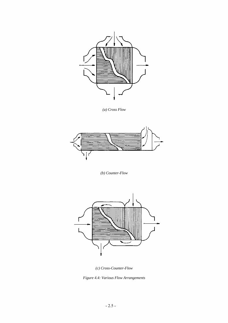
Typical devices for re-mixing the two phases within the PFHE are shown in Figures 4.14 through 4.18. Perforated “hardway” fins, used in the distribution section may improve the distribution. Sparge tubes are also common.
- 2.14 -

Figure 4.13: General Layout for Separating the Phases of a Two-Phase Fluid Entry to a Plate-Fin Heat Exchanger
Figure 4.14: Sprinkler Re-Mixer
- 2.15 -

Figure 4.15: Bubbler Re-Mixer
- 2.16 -
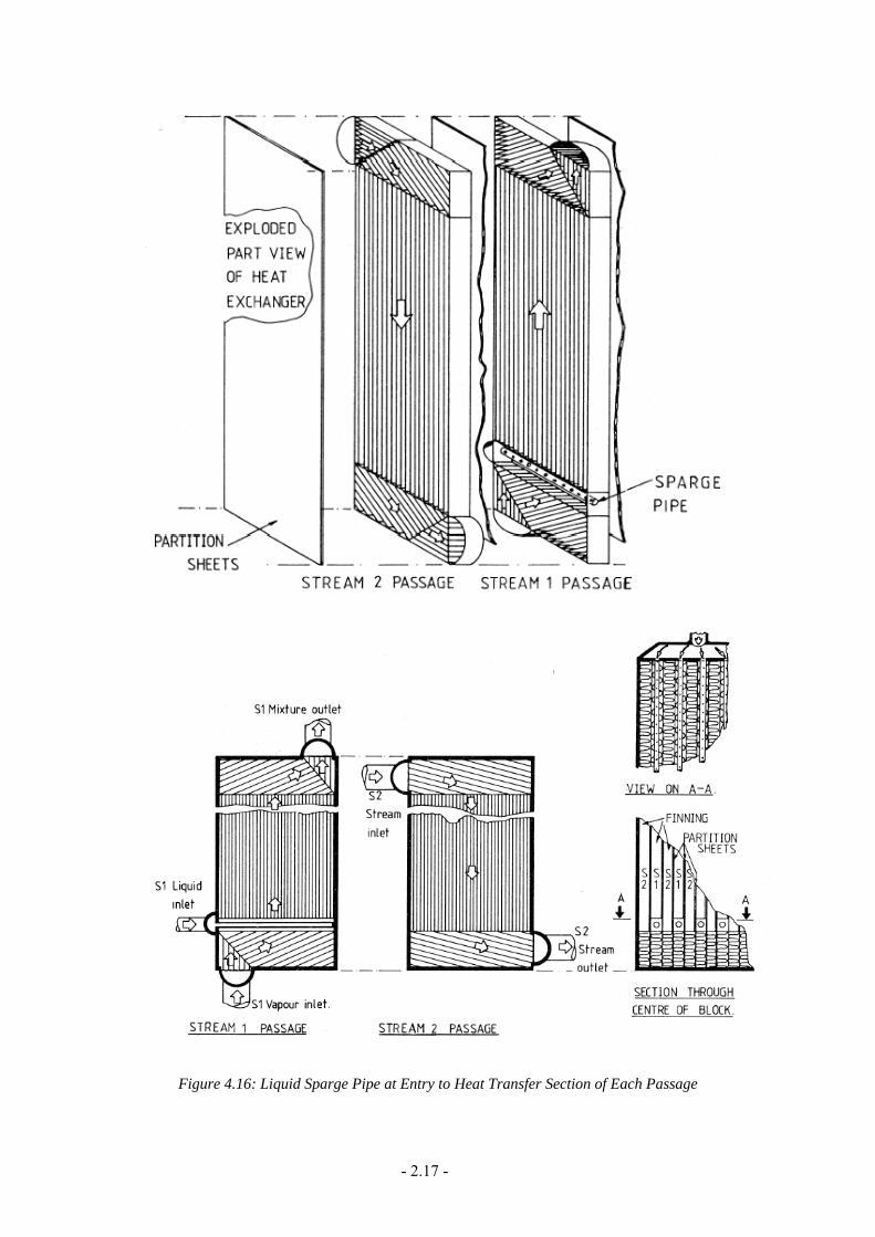
Figure 4.16: Liquid Sparge Pipe at Entry to Heat Transfer Section of Each Passage
- 2.17 -
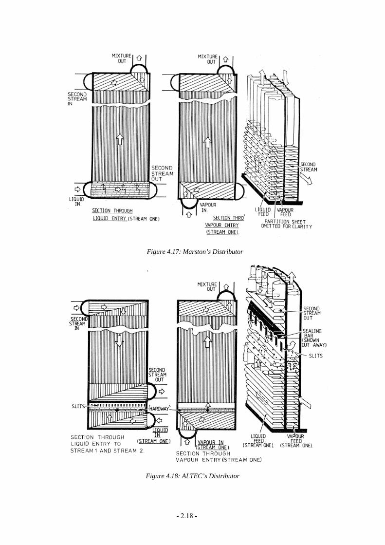
Figure 4.17: Marston’s Distributor
Figure 4.18: ALTEC’s Distributor
- 2.18 -

- 2.19 -
4.8 DESCRIPTION REFERENCES 4-1 Gregory, E.J., “Heat Exchangers”, Chapter 8 of “Cryogenics Engineering”, Academic
Press, 1986. 4-2 ALTEC Inc., “Plate-Fin Exchangers (Brazed Aluminium)”, Section 9, Engineering
Data Book, 10th Edition, Gas Processors Suppliers Association, Tulsa, Ok., USA, 1987.
4-3 “Technical Features of Sumalex”, Sumitomo Precision Products Co, Ltd, Amagasaki, Japan, 1984.

PART IV MECHANICAL DESIGN

10.0 MATERIALS
10.1 GENERAL PFHEs are designed and constructed to comply with the ASME Boiler and Pressure Vessel Code” Section VIII, Division I, or to other applicable codes. Material specifications should comply with the appropriate section of the ASME or other applicable code.
PFHEs can be, and have been, made in a variety of materials to suit a wide range of process stream compositions, temperatures and pressures. Brazing furnace dimensions for construction of PFHEs in aluminium are large compared with dimensions for other materials, because of the demand for large PFHEs by the cryogenic industry, where aluminium is the most suitable material, and because of aluminium's relatively high thermal conductivity.
10.2 ALUMINIUM Aluminium maintains excellent strength and ductility to temperatures as low as 4.3K. Aluminium and its alloys rapidly lose strength at temperatures above 100°C; and aluminium does not resist fire as well as other materials. Except for specialised aero-space and some defence applications, aluminium is not generally used for PFHEs at process temperatures above 150°C, particularly in high pressure service. Aluminium is susceptible to damage by rough handling, excessive vibration and localised unrelieved stresses. Nonetheless, the material's advantages in terms of weight and thermal conductivity over the alternatives make it the first choice for PFHE manufactures where process fluid composition, pressure and temperature permit its use. Note, however, that the thermal conductivity of pure aluminium should not be used because it is significantly higher than the alloys of aluminium commonly used for PFHEs. Also note that the value of thermal conductivity for all aluminium alloys varies significantly with temperature.
Mercury and caustic soda are both extremely corrosive to aluminium; 100% methanol is also corrosive over a period. Wet ammonia is also not suitable for aluminium. However, as neither anhydrous hydrogen sulphide nor carbon dioxide corrode aluminium in any concentration, aluminium is therefore a suitable material for many sour natural gas streams, provided they are dry.
Aluminium and its alloys are readily attacked by hydrochloric acid. Halogenated hydrocarbon solvents, such as methylene chloride, trichloroethylene, etc, are often used as degreasing agents. These compounds are readily hydrolysed by traces of water to form hydrochloric acid unless an appropriate inhibitor has been added.
Aluminium and its alloys in electrical contact with more noble metals, such as copper, will rapidly corrode. Electrical insulation should therefore be provided between aluminium or its alloys and any other metals used in the system.
For cryogenic service, aluminium alloy 3003 is generally used for the parting sheets, corrugated fins and edge-bars which form the rectangular PFHE block.
These parts are metallurgically bonded by the brazing process at temperatures about 600°C. The brazing alloy depends on the method of brazing. In salt bath brazing it is an aluminium silicon metal, alloy 4343 or 4047, and is provided on, or with, the parting sheets.
In vacuum furnace brazing the brazing alloy contains small quantities of magnesium and is used between every joint, usually by rolling it directly on to the initial plate surface. When the temperature reaches the melting point of the brazing alloy the aluminium oxide layer sublimes. The temperature is then raised some 10°C further to braze the under-lying aluminium alloy.
- 4.1 -

Headers and nozzles are made from aluminium alloys 3003, 5154, 5083, 5086, or 5454. Extended service of alloys containing 3.0% or more of magnesium at temperatures above 65°C can result in grain boundary precipitation of MgAl inter-metallic compounds which may render the material susceptible to stress corrosion. Alloys of this type should not be used at temperatures above 65°C unless tests or service experience have demonstrated that they are suitable for the specific duty. If in doubt, only alloys containing less than 3% magnesium should be used - e.g. 3003 and 5454. Consideration must be given to the external as well as internal environment.
The design stresses should be based on the fully-annealed (i.e. “O”) condition for all aluminium subjected to brazing or welding processes. For service above 60°C, all materials should be in the fully annealed condition.
Burst test procedures are demanded by a few Codes - e.g. the Japanese and Dutch, but most will permit the use of design stresses taken from the Code for the annealed condition.
Aluminium alloy 3003 begins to lose strength above 90°C. Brief excesses of temperature up to 150°C are permissible (for example, to de-frost), typically for a period of 8 hours at half the working pressure or for 24 hours at atmospheric pressure. At design temperatures above 100°C the stress-to-rupture criteria may limit the allowable stress value.
The aero-space industry uses PFHEs to temperatures around 200°C with similar alloys, but makes allowance for their reduction in strength. Some design codes do not give allowable stresses above 65°C for some aluminium alloys, e.g. alloy 5083. For design temperatures above 65°C only alloys whose allowable stresses are known should be used.
Higher temperature differences are likely between streams in hot duties compared with those in cryogenic service, and these will result in higher thermal stresses. Some manufacturers limit the temperature differences between streams to 70°C maximum, but others have satisfactory operating experience with differences up to 210°C. Flow fluctuations can themselves incur thermal differences which may impair the unit's fatigue life. Where the flow in one or both streams is intermittent, the temperature difference should not exceed 50°C in a two stream unit.
Piping is generally of the same quality metal as the header tanks, but other alloys are also used. Alloy 5083 is preferred for high pressure duty. Flanges are usually forged alloy 5454, but 5083 and others can be used.
The units are fully brazed/welded with nozzle terminations being either flanged or prepared for butt welding.
A complete list of all aluminium alloys is given in ASME VIII. BS 1470 to 1477 standards are equivalent. BS 5500 also lists aluminium alloys in the section on aluminium.
10.3 NON-ALUMINIUM Stainless steels, and most nickel alloys are used for PFHEs, particularly in high temperature service. Stainless steels have poor conductivity, but their strength allows thinner parting plates than in aluminium which offsets some of the reduction in heat transfer. The fins however are usually also made thinner in the stronger lower conductivity material, both factors combining adversely to lower fin efficiency when compared with aluminium.
Stainless steel is easier to vacuum braze than aluminium; steel has a less tenacious oxide film which more readily vaporises under vacuum.
Because of the brazing temperature, sensitization resistant grades of stainless steel, typically 321 or 316L, may be used for corrosive environments.
- 4.2 -

Copper and copper alloys have also been used for PFHEs. Titanium has been proposed, but brazing requires noble metals such as gold and is expensive - diffusion bonding is an alternative but is not yet fully developed for PFHE fabrication.
The use of the above materials in the chemical industry can be limited by the brazing process; for example, copper, nickel or nickel-chrome-phosphorus alloy is used as the braze material with stainless steel components, and so the resistance of the braze material differs from that of the components.
- 4.3 -

11.0 MECHANICAL DESIGN
11.1 INTRODUCTION The PFHE is a pressure vessel. It is required to be designed and constructed in accordance with a recognised Pressure Vessel Code.
The mechanical design of a PFHE can be divided into the conventional pressure vessel area of header tanks, nozzle compensations, pipe loads, etc., and the less familiar area of the block itself.
The design of the headers is reasonably comparable with conventional pressure vessel design handled by most pressure vessel codes. In the following areas the reference given is to ASME VIII, but other PV codes have similar procedures:
• cylinder thickness Division l para UG-27
• branch compensation Division 1 para UG-36
• end-cap thickness Division 1 para UG-34
• discontinuity stresses Division 2 Appendix 4.
The only acceptable external forces which may be applied to a PFHE are the reaction at the supports and the nozzle loads. The PFHE manufacturer will specify acceptable nozzle loads, but the associated piping systems must be designed to minimise such loads, particularly when the PFHE is constructed in aluminium. Piping loads must be assessed for all operating conditions, notably at cool-down or warm-up, especially at high or low temperatures. Such assessment is particularly important in applications calling for parallel units coupled across common headers, where any residual temperature imbalance, or temporary temperature imbalance due to upset conditions, will exert piping loads.
When the ratio of nozzle diameter to header tank diameter is suitable, the pipe load stresses can be estimated using, typically, the Welding Research Council Bulletin 107 or BS 5500 Appendix G. The stresses are usually assessed against ASME VIII or BS 5500 Appendix A.
The mechanical design of the PFHE block is closely linked to the thermal design and, ideally, the two should be carried out in parallel. This is illustrated by the fins providing secondary heat transfer surface and acting as tension members.
Pressures up to approximately 100 bar can be accommodated in PFHEs under steady state conditions, but with reversing stream pressures the maximum operating pressure may require to be lower; the limiting value will depend on the exchanger size as well as the amplitude and frequency of the pressure swing. Operation at high temperature will reduce the allowable pressure limits. Manufacturers should be consulted to determine available PFHE sizes with respect to pressure. A typical relationship for non-reversing aluminium alloy exchangers is given in Table 11/1.
It is important to note that the pressure loading on a particular channel is dependent entirely on the pressure in that channel above atmospheric pressure, i.e. no compensation can be made for pressures above atmospheric in adjacent channels. The body of the plate-fin heat exchanger can thus be seen as a stack of pressurised channels acting independently of each other, and, together, forming a pressure vessel.
- 4.4 -

The header tanks, which have no internal tension members, are an important feature of the mechanical design. Since they are attached (welded) to the body of the exchanger around their perimeter, they impose line-loads on it. There is a relationship between allowable header size, pressure, parting sheet thickness and edge-bar width. At high pressures there will be a limit to the maximum header radius, and then multiple headers may be required to maintain acceptable flow velocities.
Seismic and vibration forces will also impose additional loading, particularly at supports.
It is common practice to undertake the mechanical design and stressing of a PFHE on a routine basis. For this purpose each company has its own standard methods where calculated stresses are compared with maximum stresses permitted from the appropriate pressure vessel code. For extreme cases, or to check hand methods, companies will undertake special tests to examine various features, for example, pressure cycling, stresses at fin roots and stresses at the joins of cap sheets to edge-bars, etc.
TABLE 11/1
Typical Maximum Block Dimensions for Aluminium Alloy PFHEs
Design
pressure
bar
Block
width
mm
Block
height
mm
Block
length
mm
25 1200 1200 6200
30 1050 1050 6200
50 900 1000 6200
70 750 900 6200
90 600 900 6200
11.2 DESIGN PRESSURE
11.2.1 Derivation
The maximum allowable design pressure for the corrugation is determined by either burst testing or calculation. The procedure is applicable to PFHEs in any material:
• Burst test
A representative sample of matrix is brazed and pressure-tested to destruction. ASME VIII, Division 1, Paragraph U.G. 101 gives a typical procedure wherein a safety factor, approximately five, is applied to the burst pressure to arrive at the maximum allowable design pressure for the fin corrugation. Other code procedures use slightly different safety factors.
The maximum allowable design pressure derived in this manner is based on the assumption that all tolerances are favourable - i.e. the burst test sample is of maximum possible robustness. In practice the manufacturer must further reduce the maximum allowable design pressure by the ratio of least to most favourable tolerance.
Where a large number of samples of a known geometry have been tested and shown to fail predictably, manufacturers can obtain Code Authority agreement to divide the burst test pressure by a smaller factor; typically for ASME VIII, Div 1, this may be about 4 instead of 5.
• Calculations
- 4.5 -

The calculation method must be approved by the appropriate Pressure Vessel Approval Authority. A braze factor may be applied to the calculated value to take account of imperfections in fin shape, etc. Once the calculation method is approved it should be possible to use normal code safety factors on the fin mechanical properties, thus achieving a higher design pressure than the burst test method.
Where Code design procedures apply to PFHEs, the allowable stresses are derived by dividing the ultimate tensile stress by 4, or the 0.2% proof stress by 1.5, whichever is the smaller.
11.2.2 Effects of Cyclic Duties
Composite blocks are not normally recommended for any form of cyclic duty. Composite blocks are blocks welded together in parallel to increase the overall flow cross-section when such is limited by the method of manufacture.
Parting sheet failure alongside edge-bars can occur in cyclic service where passages are badly distributed between warming and cooling streams.
• Pressure Cycling
The ability of an exchanger to withstand reversing pressures is frequently proven by accelerated cycle testing of a representative exchanger, i.e. a full cross section with full-size header tanks.
The design life is determined using paragraph 6-170 of ASME VIII, Division 2, or equivalent.
• Thermal Cycling
Pressure cycling is a well understood and predictable phenomenon, but thermal cycling data is much more scattered. The aircraft industry imposes cycling tests on the manufacturers, but most process industry clients do not. A thermal cycling rate of 1°C per minute is generally considered acceptable, and a 2 or 3°C per minute cycle rate has been satisfactorily achieved.
It is most important where there is any degree of cyclic duty that the layers be arranged in the stack to give a uniform temperature profile across the metal of the exchanger. This is specially important if composite blocks have to be used.
11.3 TEMPERATURE The overall maximum temperature difference between streams can be typically 50°C. Ethylene heaters have been successfully operated with temperature differences of up to 100°C.
Where it is important to minimise thermal stress, it will be necessary to calculate the passage-to-passage heat transfer and determine the temperature profiles for different operating conditions. The passage arrangements should then be optimized to give the lowest possible temperature differentials.
If blocks are joined by welding, the passage distribution must be chosen to minimise temperature discontinuities across the joint during operation otherwise weld failures may occur.
Operation at high temperature will reduce the allowable pressure limits.
- 4.6 -

11.4 MATRIX (BLOCK) DESIGN
11.4.1 Fins
A simple one-dimensional model approach for the fins treats them as tension members restraining the two attached parting sheets, mainly in the direction of the plane of the fins, see Figure 5.1. The tensile stresses in the fin limbs, treated as straight members, can be arranged to be less than a given allowable stress for the chosen material at the desired temperature by providing sufficient fins with adequate cross-sectional area. The bending stress near the curved root of a real fin is dealt with by Reference 11-2.
Where exchangers are installed inside another vessel, e.g. internal reboilers, the fins in any closed dummy passages, such as are used for external strengthening, must be strong enough in compression to withstand the external pressure.
In some cases where it is important to avoid any form of blockage, e.g. oxygen reboilers, a small gap should be provided between the individual fin pads. Prior to brazing, the gap is maintained by the insertion of permanent spacer pieces which will not restrict the flow. This gap eliminates any local restriction where the fin pads meet.
11.4.2 Parting Sheets
The parting sheet acts as a flat plate with shear loads applied along the edges due to pressure on the edge-bars. See Figure 11.1. Additional loads are applied where the header tanks are attached.
In severe applications the additional stress on the parting sheet arising from the effects of pipe loads on the nozzles should be considered.
11.4.3 Cap Sheets
The cap sheets are usually thicker than the parting sheets to give protection to the block against physical damage. Discontinuity stresses occur in the cap sheets where they meet the edge-bars. These discontinuity stresses arise because of the dissimilar rigidity of the edge-bars and the fins. See Figure 11.1. The stresses in the edge-bars can be obtained by estimating the shear forces in the join between the edge-bars and the parting sheets.
Figure 11.1: Deformation of Core Subjected to Internal Pressure
- 4.7 -

11.4.4 Headers
Headers are very difficult to analyse accurately. They can be treated as semi-cylindrical pressure vessels to obtain a rough approximation of the tensile stress within the chosen radius. Thick cylinder design may be required for small headers with a small radius-to-thickness ratio. The ends of the headers will be sealed by plates called “end-caps” and these will add discontinuity stresses at the joins. Further discontinuity stresses will arise at the penetration of the nozzles into the headers. In practice the header tank thickness and nozzle compensation requirements are determined using appropriate pressure vessel design code formulae for cylinders and nozzles.
It has been shown that end-caps of ‘orange peel’ or ‘petal’ profiles provide header tanks with greater protection against fatigue failure than flat end-caps. Petal end-caps should be used for all header tanks in reversing services.
11.4.5 Supports
Of the many ways of supporting PFHEs the most common are:
• brackets on cap sheets
• brackets on edge-bar face
• shear plates welded to cap sheets with angle supports
• foot support welded to cap sheet at the end of the exchanger.
Supports must be provided with oversize or slotted holes to accommodate the change in block dimensions, or its position, at operating or upset temperature.
The foot-type support is sometimes given sufficient length to allow for expansion and contraction of the block.
Where there is thermal cycling a low friction material, e.g. PTFE, should be provided under the supports.
Angle supports welded to the edge-bar face should not extend for the full width of a composite exchanger.
Some manufacturers will supply a continuous angle between the shear plates. It is recommended that the centre portion of this angle be removed on installation; this is essential if there is a thermal cycle. See Figure 11.2.
Figure 11.2: Shear Plate Support Angle (courtesy Air Products Ltd.)
- 4.8 -

11.4.6 Vents and Drains
See Figures 11.3 A and B, and Figure 11.4.
Dead areas in layers, e.g. below free draining diagonal bars and below dividing bars in two-tier side tanks, should be freely vented. This can be achieved by venting the space to another operating layer or to a separate header tank. The former option is only used where a leak between the two streams concerned would be of no consequence.
PFHE layers should be arranged so that there are no major undrained areas. For example, where there are two side tanks, one above the other, as shown in Figure 11.3B an internal horizontal dividing bar is included at the bottom of the upper port opening as in Figure 11.3A. Manufacturers have various methods of satisfying this requirement.
Layers in which water may condense during operation or shutdown, should be designed so that they drain freely into the header tanks. This is normally achieved by an internal diagonal bar or a sloping bottom bar. See Figure 11.4.
Figure 11.3: Venting and Draining (courtesy Air Products Ltd.)
- 4.9 -

Figure 11.4: Dead Space Draining (courtesy Air Products Ltd.)
11.4.7 Submerged Exchangers
Any exchanger which will be submerged in a cryogenic liquid, e.g. an internal reboiler, should be free of any enclosed spaces in which liquid could enter and become trapped, e.g. through a porous weld. All attachments, e.g. support brackets, should be stitch welded.
11.5 CALCULATION METHODS At the thermal rating stage it is important that the thermal designer has some means for calculating fin and parting sheet thicknesses. Normally, where the manufacturer carries out both thermal and mechanical design, or where an experienced user carries out the thermal rating, correct thicknesses will be available to the designer by in-house application of the appropriate pressure vessel code, or from records of pressure ratings for the various fin characteristics. In other situations where the thermal rating is carried out for budgetting purposes or in feasibility studies, the rating engineer must know at least the approximate minimum thicknesses for fins, sheets and bars.
The following equations are taken from the Japanese “High Pressure Gas Control Law” and, used in isolation, represent an idealised situation; they do not take into account many of the restrictions mentioned in the previous section. For example, the header tank size and pressure have a significant affect on the required parting sheet thickness, and any method which does not take this into account could be misleading, particularly for higher pressures. In practice, the Japanese Code requires confirmation of the calculated thicknesses by an hydraulic test on a representative sample PFHE to four times the design pressure. Without such confirmation these equations must only be used for first approximations and are not a substitute for proper mechanical design.
11.5.1 Fin Minimum Thickness
t = ffn
Pσ
x )( holeh
h
dpp−
(m) [11.1]
where
P = relevant stream design pressure (Pa)
nf = number of fins per metre (m-1)
- 4.10 -
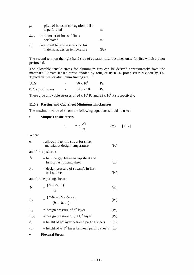
ph = pitch of holes in corrugation if fin is perforated m
dhole = diameter of holes if fin is perforated m
σf = allowable tensile stress for fin material at design temperature (Pa)
The second term on the right hand side of equation 11.1 becomes unity for fins which are not perforated.
The allowable tensile stress for aluminium fins can be derived approximately from the material's ultimate tensile stress divided by four, or its 0.2% proof stress divided by 1.5. Typical values for aluminium finning are:
UTS = 96 x 106 Pa.
0.2% proof stress = 34.5 x 10⁶ Pa.
These give allowable stresses of 24 x 106 Pa and 23 x 106 Pa respectively.
11.5.2 Parting and Cap Sheet Minimum Thicknesses
The maximum value of t from the following equations should be used:
• Simple Tensile Stress
t1 = s
mPbσ
' (m) [11.2]
Where
σs = allowable tensile stress for sheet material at design temperature (Pa)
and for cap sheets:
'b = half the gap between cap sheet and first or last parting sheet (m)
Pm = design pressure of stream/s in first or last layers (Pa)
and for the parting sheets:
'b = 2
)( 1++ nn bb (m)
Pm = )(
)(1
11
+
++
++
nn
nnnn
bbbPbP
(Pa)
Pn = design pressure of nth layer (Pa)
Pn+1 = design pressure of (n+1)th layer (Pa)
bn = height of nth layer between parting sheets (m)
bn+1 = height of n+1th layer between parting sheets (m)
• Flexural Stress
- 4.11 -

t2 =
5.0
2 )2( ⎟⎟⎠
⎞⎜⎜⎝
⎛
sf
m
nPσ
(m) [11.3]
nf = 5.01 )( +fnfn nn
• Shear Stress
t3 = )2( sfn
Pmτ
(m) [11.4]
where
sτ = allowable shear stress for sheet material at design temperature (Pa)
11.5.3 Edge-Bar Minimum Thickness
tb = 5.0
25.1⎟⎟⎠
⎞⎜⎜⎝
⎛
bb
Pbσ
(m) [11.5]
where
bb = gap between sheets (m) σb = allowable tensile stress for bar material at
design temperature (Pa) P = the relevant stream design pressure (Pa)
11.6 LITERATURE REVIEW • 11-1 “Three-Dimensional Structural Analysis of the Plate-Fin Heat Exchanger”, N.
Akagawa et al, 84 PVP 7, ASME.
This work deals with internal pressure loading only. The analytical method uses a finite element static analysis to examine levels of stresses. A two-dimensional analysis shows that an anisotropic model of the fin/parting sheet structure can be used to predict stresses in the x plane i.e. edge-bar to edge-bar and not close to headers, which will agree well with stresses measured on the inside and outside of the PFHE near the edge-bars of a full-scale model. Figure 11.1 shows the deformation pattern of the core under internal pressure.
A three-dimensional analysis deals with the stress systems around the nozzle and header of an end centre-entry arrangement. The end of the block in the vicinity of the header end-cap has been found to be the most sensitive region for stressing. Figure 11.5 shows the deformation pattern here.
- 4.12 -

Figure 11.5: Deformation of the Core in the Vicinity of End Cap
• 11-2 “Fatigue Strength of Corrugated Fin type Heat Exchangers”, Mizoguchi, T., et al, 82 PVP 29, ASME, (1982).
In this paper the authors examine the structural analysis of the core using finite element methods and model the corrugated finning by an equivalent, anisotropic material. They deduce the fatigue curve for the brazed section of the corrugated fin and parting sheet junction for a cyclic loading of one stream. They then estimate the fatigue life in terms of the known fatigue strength of the material.
This paper is closely linked to the previous one.
The finite element analysis considers also the fin root -i.e. the curved portion of the fin in the proximity of its attachment to the parting sheet. At this section, the highest bending moments, coupled with the highest tensile stresses (particularly under fatigue loading) exist. Experimental results from small scale units have been compared with the predicted methods with reasonable success.
11.7 CONCLUSIONS Current methods of stress analysis of complicated three-dimensional structures such as plate-fin heat exchangers are now available and are being applied to these exchangers. These methods can be used to predict stresses, particularly in complicated regions or at discontinuities. These stresses may be used to validate the normal stress analysis methods used for production exchangers. These stresses can also be compared with allowable stresses from codes such as ASME, etc. In this manner it is possible to produce confidence that an exchanger can be built to withstand pressures either under static, cyclic or shock loadings. At this time little information is available about the results of thermal stressing with either static or repeated cycling.
- 4.13 -

12.0 DESIGN AND APPROVAL REQUIREMENTS
12.1 INTRODUCTION Usually the relevant Pressure Vessel Code is that of the country where the PFHE is to operate -the “user country”. Approval that the vessel design meets the relevant Pressure Vessel Code should be obtained before the vessel is manufactured. Approval is authorised by the “Code Authority”, which is usually the National Pressure Vessel Code Authority of the user country, but, in the case of the USA is an ASME approved inspection authority. Some Code Authorities will approve designs themselves but some may delegate design approval to other authorities.
In countries where there are no specific code or approval requirements, the ASME code is generally used, with inspection by the Purchaser or an organisation nominated by the Purchaser. In these cases the code marking (“U” stamp) is generally not applied.
Inspection and ultimate approval of a coded PFHE construction may be delegated by the Code Authority or the Purchaser to an Independent Inspection Authority usually from the country of origin, independent of both Purchaser and Manufacturer. A list of authorized foreign inspection organisations is maintained by the Approval Authority of the user country. Any modification to the design or the material used should be confirmed with the user country's Approval Authority rather than the Independent Inspection Authority.
Reference 12-1 lists the Pressure Vessel Codes and Code Authorities applicable to stationary pressure vessels in 98 countries. English translations of all the major foreign design codes are available from British Standards Institution. The ASME Code is also available from BSI.
12.2 SELECTION OF COMMON NATIONAL CODES
• France
Syndicat National de la Chaudronnerie de la Tolerie et de la Tuyauterie Industrielle (SNCTT).
French code for the construction of Unfired Pressure Vessels (CODAP 85).
• Germany (Federal Republic) Technische Regeln für Dampfkessel (TRD). TRD - Technical Regulations for Steam Boilers. Arbeitsgemeinschaft Druckbehalter Merkblätter (AD -Merkblätter). AD - Data Sheets. Technische Regeln Druckbehalter (TRB). TRB - Technical Regulations for Pressure Vessels.
Technische Regeln Druckgase (TRG). TRG Technical Regulations for Pressurized Gases.
• Italy
Insituto Suiperiore per la Prevenzione e la Sicurezza del Lavora. ANCC Code - Technical Specifications for the Design, Construction and Operating Requirements for Pressure Vessels and Steam Generators.
• Netherlands
Regel voor Toestellen Onder Druck. Rules for Pressure Vessels.
- 4.14 -

- 4.15 -
• Sweden
Tryckkarlsnormer (1973) Hallfastnetsberakning av Tryckkärl. Pressure Vessel Code (1973) -Stress Calculations for Pressure Vessels.
• United Kingdom
British Standards. BS 5500
• United States America
American Society Mechanical Engineers -Boiler and Pressure Vessel Code. The ASME Code is accepted in many countries.
12.3 REFERENCES 12-1 “Boilers and Pressure Vessels - an International Survey of Design and Approval Requirements”, Technical Help to Exporters, British Standards Institution, Milton Keynes, U.K., 4th Edition (1987).

APPENDIX A GLOSSARY OF TERMS

GLOSSARY The following terms are used in this Guide. In many cases there will be other alternatives in common use in the industry. It is not intended that this glossary should be definitive; it is only intended as a guide to the reader of this document. ASME American Society of Mechanical Engineers.
Block Assembly of parting plates, corrugations and edge seals, dip-brazed as a unit. Also known as a “core” or a “matrix”.
Brazing The joining of two metals by melting a lower melting-point alloy between them.
Bubbler Device to reintroduce vapour to liquid in two-phase PFHE operation.
Calandria Part-submerged boiler device within a column.
Cap sheets Outermost plates, usually thicker than parting sheets to withstand mechanical damage. Also known as “outside sheets”, “outer cover plates” or “end plates”.
Certification Quality control procedure - e.g. to ensure that the specified material is used in the construction.
Chugging A form of flow instability.
Co-current Hot and cold streams flow in same direction.
Cold-box Metallic enclosure containing the PFHE/s and associated equipment.
Convective boiling Evaporation from a liquid film without the growth of bubbles.
Core Same as “block”.
Corrugations Set of fins between plates.
Counter-current Hot and cold streams flow in opposite directions.
Cross-current Hot stream flows at right angles to cold stream.
Cross-counter-current Multipass cross-current hot (cold) side with pass sequence counterflow to single-pass cold (hot) side.
Cryogenic Traditionally taken as any temperature below 100K, now more generally taken as any temperature below ambient.
Density wave oscillations
A form of instability caused by feed-back of pressure drop perturbations.
Dip-brazing The method of brazing corrugated sheets to parting, cap sheets and edge-bars in a molten salt bath.
Distributors Device to direct streams appropriate passageway.
Double-banking Two adjacent passages for cooling (heating) streams.
Dry-out Loss of liquid film on heating surface.
Dummy passages Passages within the block not intended for stream flow that arises from special construction features, such as welding together blocks or the provision of a passage beneath cap sheets for welding purposes.
Edge-bars Solid bars brazed around edges of each parting sheet with gap on opposite sides to form enclosed passage.
Effectiveness (thermal)
Fraction of total theoretical heat exchange actually accomplished.
Efficiency (fin)
Measure of the loss of heat transfer driving force in secondary surface caused by metal thermal resistance.
End-cap The closing plate at the end of a header tank.
-A1 -

End-entry Stream enters in line with thermal section corrugations -i.e. at the end of the block.
Fin One of several metal strips joining adjacent flat plates.
Fin efficiency See “Efficiency”.
Fin height The distance between adjacent parting sheets.
Fin root Base of fin where brazed to parting sheet
Fins - hardway Perforated or serrated fins with the corrugations set at right angles to the flow.
Fins -herringbone Wavy corrugations to increase turbulence.
Fins -lanced Also known as “multi-entry” or “serrated”.
Fins -perforated Uses sheet which is pre-punched before pressing the corrugations
Fins -plain Straight, smooth corrugations.
Fins -serrated Offset short lengths of fin which promote turbulence.
Fins -wavy Same as “herring-bone”.
Flux Chemical which cleans and promotes surface tension between metals to allow ingress of molten brazing alloy.
Hardway (finning) The use of perforated with the flow across the fins (i.e. through the perforations).
Header tank Half-cylinder welded across all layers which directs stream through ports into selected distributors. Also known as a “header”.
Heat release curve The temperature of a stream plotted against its enthalpy -also known as “heat curve”, “temperature-enthalpy curve” or “T-ΔH diagram”.
Instability Flow surge.
Interrupted fin Same as serrated fin.
Jig A framework into which the assembled stack of plates and fins is mechanically restrained prior to brazing.
Layer stacking arrangement
Order in which layers of plates and fins for different streams are stacked - usually arranged to maximise thermal effectiveness of PFHE, also known as “stacking pattern”, “layer order”, or “layer sequence”.
Ledinegg instability A form of flow instability caused by the possibility of more than one mass flow rate for a given pressure drop across a channel.
Maldistribution Uneven spread of one or other phase across parallel flow passages, such as exist within a layer, between layers or between blocks.
Mass velocity Mass flowrate per flow cross-sectional area –also known as “mass flux”.
MIG Manganese inert gas welding.
MTD Mean temperature difference.
Multi-stream More than one stream heating or cooling.
NTU Number of transfer units -a measure of the difficulty of a given heat transfer operation.
Nucleate boiling Bubble growth and subsequent vaporisation.
Outer cover plate Same as cap sheet.
Parting sheets Flat plates, typically 0.5 to 1 mm thick, separating passages joined by corrugated fins -also known as “separating plates” or “partition plates or sheets”.
Perlite Granular insulation.
PFHE Plate-fin heat exchanger.
Plate-fin Corrugated fin brazed to plate.
Quality Mass fraction of flow which is vapour.
-A2 -

-A3 -
Saturation At the boiling point of a pure fluid.
Scuff plate Expendable plate, often made of aluminium, used to protect the edges of a PFHE whilst lifting.
Sealant Chemical used instead of welding to block leaks.
Sealing bars Same as edge-bars.
Separator Unit used to separate the gas and liquid upstream of a PFHE.
Side-entry Stream enters at right angles to thermal section corrugations -i.e. on the side of the block.
Single-banking All adjacent layers contain streams of opposite temperature gradient -e.g. hot-cold-hot, etc.
Sparge pipe Device to reintroduce gas into liquid in two-phase PFHE operation.
Sprinkler Device to reintroduce liquid droplets into gas in two-phase PFHE operation.
Stratification Flow separation into liquid and vapour layers.
Subcooled Below the bubble point.
Superheated Above the dew point.
Surface area Total area available for heat transfer.
Temperature cross Where the exit temperature of the hot fluid is below the exit temperature of the cold fluid.
TIG Tungsten inert gas welding.
Thermal cycling Repetition of temperature cycle which can induce fatigue, especially in aluminium.
Thermal effectiveness Measure of thermodynamic efficiency. See “effectiveness” -also known as thermal efficiency.
Thermal oscillations A form of instability.
Vacuum brazing The method of brazing corrugated sheets to parting sheets, cap sheets and edge-bars in a vacuum furnace.

PART V
HARDWARE

13.0 MANUFACTURING
13.1 GENERAL The principles of PFHE manufacture are the same for all sizes and all materials. The parting sheets, corrugations, edge-bars and cap sheets are held together in a jig under a predetermined load, placed in a furnace and brazed to form the PFHE block. The header tanks and nozzles are then welded to the block.
Differences arise in the manner in which the brazing process is carried out. Most metals, such as stainless steel, copper and nickel alloys, can be brazed satisfactorily in a vacuum furnace, where the high temperature and low pressure easily removes any oxide layers. Aluminium, however, has a tenacious oxide layer that requires either a molten salt bath to dissolve off the oxide as well as supplying the brazing heat, or else a higher vacuum and special braze metal.
The maximum block size that can be brazed in either a salt bath or vacuum furnace is defined by furnace dimensions, furnace lifting capacity and heat input rate. Higher design pressures increase the block weight and also the heat capacity, and hence the heat soak time. The increased soaking time may be uneconomic, and, in the case of aluminium, may upset the brazing chemistry; in such cases it may be more satisfactory to braze two separate smaller blocks for use in parallel.
13.2 MANUFACTURE OF ALUMINIUM PFHEs The sales value of aluminium PFHEs at present is greater than that of PFHEs in all other materials. After initial development in the aero-industry, where their light weight and compactness was an asset, the cryogenics industry adapted the PFHE to low temperature duties, where aluminium is an ideal material. The manufacturing techniques have been improved over the past 40 years.
The production methods do not differ greatly among manufacturers. The principal stages are shown in Figure 13.1 for salt bath brazing and Figure 13.2 for vacuum brazing.
Most of the components in a PFHE are of relatively thin material, even for quite high pressure duties, so much of the raw material is delivered to the manufacturer in rolls. It is then cut to the correct dimensions for the parting sheets and cap sheets. It is at this stage that care is needed to ensure the correct material is always used, since, unlike steel plates for shell and tube heat exchangers, the individual sheets must not be stamped with any classification, to avoid problems with the brazing operation.
The particular fin corrugation is made by running the roll through a press carrying a profiled die. Individual finned sections are cut to the correct width and length to match the parting and cap sheets, allowing for the addition of distributor sections at both ends if applicable. Distributor finning, which is often of a different profile but always the same height as the heat transfer finning in the same passage, is similarly cut to the correct size.
A great many alternative corrugation forms are available as well as many different fin thicknesses, heights and spacings. It is important that the tolerances allowed in the PFHE design are maintained in manufacturing the fins, particularly fin thickness and correct profile. Flatness is also important to ensure an even stacking load is exerted on every sheet before brazing.
Edge-bars are cut from stock. Before assembly, all components are degreased using solvent, acid-etched, detergent-washed, rinsed and oven-dried. The clean components are assembled to form the required number of layers and the stack is assembled into a binding jig, to form the internal matrix of the PFHE. Figure 13.3 shows the components of a single layer. Figure 4.3 shows five such elements stacked in a counter-flow arrangement.
- 5.1 -

The jigs are loaded in a manner which will allow the block first to expand as it heats up, then to collapse back to pre-set stops when the brazing metal melts. The loading is calculated to take up the corrugation height variations across each layer to ensure good contact between the fins and sheets and brazing metal.
The normal material for aluminium PFHE manufacture is alloy 3003 for the sheets, corrugations and edge-bars. Between the sheets on one side and the edge-bars and corrugations on the other, is placed a thin foil of a similar alloy plus about 7% silicon, which metals about 50°C lower than the other components. Normally the sheet is purchased with the Si/Al alloy already rolled on to both sides.
In the salt bath process, the stacked assembly is preheated in a furnace to about 550°C and then dipped into a bath of a fused salt mainly composed of fluorides or chlorides of alkaline metals. Heating of the block is largely achieved by convection through the molten salt. Larger blocks are therefore dipped more than once to ensure that salt does not congeal in the cooler centre of the block thereby restricting heat transfer for good brazing.
The molten salt is both flux and heating agent; it maintains the furnace at a uniform temperature. In addition, the density of the molten salt is close to that of aluminium, reducing the risk of gravity deforming the assembly which, being close to melting, is of low strength. The preheat furnace ensures that the temperature of the assembly is uniform and a few degrees below melting point of the braze metal. Then on entry into the salt bath, the braze metals melts and flows by surface tension along the junctions between the sheets, corrugations and edge-bars.
The salt bath temperature must be carefully controlled. The braze material melts between 577 and 615 °C. The melting point of the parent metal is about 660°C. Thermocouples set into the unit indicate when the brazing temperature has been achieved. The braze metal filler and the parent metal diffuse into one another, forming an integral bond, both mechanically and chemically.
After salt-bath brazing the block contains a residue of the salt, which is deliquescent and corrosive. The block is cooled, then washed for several hours in successively cleaner water. Then follows a wash in 7% nitric acid solution. Finally the block is thoroughly washed in demineralised water, taking periodic readings of salinity to ensure no salt remains. The block must then be dried
Some distributor designs, diagonal for example, contain blocked passages which would not be wetted by the molten salt nor by the wash liquids. In such cases the finning is perforated to allow perforated to allow complete penetration.
- 5.2 -

Figure 13.1: Manufacturing Procedure of Dip Brazing with Flux (courtesy Linde)
- 5.3 -

Figure 13.2: Manufacturing Procedure of Flux-Free Brazing in a Vacuum
(courtesy Linde)
- 5.4 -

Figure 13.3: Single Layer Assembly of Parting Sheets, Corrugations and Edge-Bars (courtesy Marston Palmer Ltd.)
In the vacuum furnace process, the oxides of aluminium are sublimed in the solid state by trace quantities of magnesium in the braze metal at 590°C under high vacuum. No flux other than the braze metal itself is required. No separate pre-heating furnace is required. The assembled block is heated to brazing temperature by electric radiation to the exposed surfaces and by conduction from there into the interior of the block. The absence of oxygen in the brazing furnace is ensured by application of a vacuum, followed by filling with inert gas, and re-evacuating the furnace as many times as experience dictates. No washing and drying of the brazed block is required.
Heating by radiation in a vacuum is less easily controlled than by convection in a salt bath. Vacuum furnaces therefore employ zones of radiant panels, each separately controlled. Thermocouples are inserted into the block to indicate local temperatures, which guide the operator or computer to the correct setting for each heating zone. The complete process can be programmed; it is, however, more usual for the first run of a batch to be controlled manually, with the computer repeating the same sequence of zonal heating on subsequent runs on identical blocks.
Disadvantages of the salt bath compared with the vacuum technique include the extra stages of pre-heating, subsequent cooling, washing and drying; the need to dip the assembly repeatedly into the salt bath with consequent risk of displacement of the elements; the disposal of contaminated wash water; the risk of flux residue in the block with subsequent risk of blockage, uneven distribution, product contamination and corrosion; the additional energy required to keep the salt molten even when no brazing is being carried out; the larger size of a salt bath compared with vacuum furnace.
- 5.5 -

Disadvantages of the vacuum technique include the need for very close temperature control in the absence of a large salt bath heat capacity, since there is a very small margin between the melting point of the braze metal cladding and the parent aluminium alloy sheet or finning. Heat input to the centre of the block has to be by conduction, which controls the minimum partition sheet thickness in large blocks. Although the vacuum process produces a clean product, it is less tolerant to contamination than the salt bath process and demands a higher standard of cleanliness of the initial assembly.
From either the salt bath or vacuum process the next stage is to weld on the header tanks and nozzles. The welding process may be TIG or MIG, carried out by qualified welders and in accordance with qualified welding procedures.
The PFHE is then tested to satisfy the Pressure Vessel Code and Purchaser requirements. Such tests will include overall hydraulic or pneumatic design pressure tests on each stream, and may include leak, flow and pressure drop tests on individual streams. Where several blocks are to be assembled in parallel, the pressure drop test enables an optimum selection to be made as to where each block is to be located.
If required, the PFHE or PFHEs are assembled into a cold box - that is, an enclosure containing the exchangers, pipework and insulation. After final inspection, the finished product is packaged and shipped. To ensure complete dryness, the packaged product has all nozzles closed by temporary weld caps or blank flanges, and the internals are filled with an inert gas such as nitrogen with a dew point significantly below the minimum temperature to which the PFHE is likely to be exposed in transit to site or in storage.
13.3 NON-ALUMINIUM PFHEs Salt bath brazing is not necessary for metals other than aluminium that are currently used for PFHEs. Vacuum furnaces are used but at a lower vacuum and higher temperatures, with somewhat less stringent temperature controls. The braze metal for stainless steel is usually a nickel-chrome-phosphorus alloy. Otherwise the manufacturing process is similar to that for aluminium PFHEs.
For a given pressure rating, stainless steel fins can be thinner than the weaker aluminium, which, combined with stainless steel's lower thermal conductivity, usually produces optimum heights for stainless steel fins that are lower than for aluminium fins. The toughness of stainless steel also tends to restrict the range of serrated finning which can be formed.
13.4 MANUFACTURING REFERENCES
13-1 Dr Wolfgang Diery, “The Manufacture of Plate-Fin Exchangers at Linde” Reports Science & Technology, Linde, No. 37, 1984.
14.0 QUALITY ASSURANCE The Manufacturer is required to establish and exercise suitable Quality Assurance Procedures for all the manufacturing and testing operations, to ensure that the manufactured equipment conforms to the applicable Design Codes and to any specifications given by the Purchaser.
The principles described in this PFHE Guide, particularly those in Section 15.0 on Inspection, should form a useful guide to the Quality Assurance Procedures necessary to ensure a quality product.
In any case, the Quality Assurance Procedures to be used must be agreed with the Purchaser prior to start of manufacture.
- 5.6 -

15.0 INSPECTION AND WORKS TESTS
15.1 GENERAL
15.1.1 Scope
The purpose of inspection is to ensure that the plate-fin heat exchanger (PFHE) meets the requirements of the relevant Pressure Vessel Code, this Guide and any special Purchaser's requirements. The scope and requirement for inspection shall, as a minimum, ensure that the requirements of the relevant Pressure Vessel Code are met.
Inspection procedures for PFHEs are not covered by the Pressure Vessel Codes. The inspection procedures stated here are those commonly required by experienced Users and Purchasers of PFHEs. Either the Independent Inspection Authority or the Purchaser's nominated Inspection Authority may require some of these procedures to be modified for special circumstances, and in such cases the modified procedures shall take precedence.
Pressure Vessel Code inspections shall be carried out by the Independent Inspection Authority. Non-Code items, normally carried out by the Purchaser's Inspector, may be delegated to the Independent Inspection Authority by the Purchaser. From hereon in the text “nominated” will be used to cover both the code and non-code inspection authority.
15.1.2 Access and Information Supply
The Manufacturer shall allow the Purchaser's Inspector or the Nominated Inspection Authority reasonable access to the works at all times during which the work is in progress. The Manufacturer shall supply to the Purchaser or the Nominated Inspection Authority all necessary certification of materials, shop test data, etc, to verify that the requirements of the Pressure Vessel Code, this PFHE Guide and any Purchaser's requirements have been met.
15.2 DRAWING APPROVAL Fabrication should not start until all relevant Manufacturer's drawings have received an approval stamp from the Code Authority or the Nominated Inspection Authority, and approval has been confirmed by the Purchaser.
15.3 WELDING PROCEDURES AND WELDERS QUALIFICATIONS Before fabrication, the Nominated Inspection Authority shall confirm that the Manufacturer's Welding Procedure Specifications and Procedure Qualifications are fully in accordance with the design, the Pressure Vessel Code, and the Code Authority requirements. The Nominated Inspection Authority shall also ensure that all Welders Qualifications are current and related to the Procedure Specification. Where procedures or operators are not suitably qualified, the Nominated Inspection Authority shall witness such qualifying tests and endorse qualification documentation accordingly or issue separate certificates.
15.4 MATERIAL CERTIFICATION Certification of materials used in the construction of PFHEs differs from more common pressure vessels in that much of the pressure holding material is purchased in rolls, not plates, and identification of cut lengths can be difficult if close quality control is not exercised.
The Nominated Inspection Authority shall identify all pressure retaining materials in accordance with the particular Pressure Vessel Code requirements by the procedures 1,2 and 3 below as appropriate, or by such procedures as are agreed with the Code Authority.
1. Correlate the batch number marked on materials with material certificates for the same.
- 5.7 -

2. Correlate materials against material certificates and witness the transfer of markings from plate to components.
3. As 2. plus witnessing of mechanical tests to Pressure Vessel Code requirements on selected test pieces.
Note that the Nominated Inspection Authority is required to select the procedure appropriate to the requirements of the Code Authority or that agreed between the Purchaser and Code Authority specifically for the contract.
The type of material certificate shall be as defined in the design Code or by the Code Authority.
15.5 CORRECT ASSEMBLY The Nominated Inspection Authority shall be satisfied that components are correctly assembled in accordance with the approved drawings. Correct assembly shall be taken to include correct dimensional fit-up and tolerances, freedom from any visible defects in the parting sheets and correct orientation of streams and nozzles.
15.6 BRAZING After brazing, but before attachment of the header tanks, the Nominated Inspection Authority shall inspect passage openings in the block to ensure these are all clear of obstructions and clean to the required standard.
For salt bath brazed PFHEs the Nominated Inspection Authority shall, at this stage, check for cleanliness of the work by confirming that all the passages for all process streams have been rinsed with demineralised water and have been tested with silver nitrate solution to ensure they contain no brazing salt residues.
15.7 WELD PREPARATIONS AND ALIGNMENT The Nominated Inspection Authority shall inspect the weld preparation and alignment of each header tank to the block and ensure that the header tank attachment does not obstruct the ports into the block.
The weld preparations and fit-up of all nozzles, pipes, manifolds, brackets, etc. shall also be checked and alignments between them inspected.
15.8 WELD INSPECTION Details of the Manufacturer's proposed non-destructive weld inspection procedures shall be submitted for approval to the Nominated Inspection Authority and the Purchaser before starting inspection.
Additional non-destructive tests beyond the requirements of the Pressure Vessel Code shall be carried out if called for by the Purchaser.
The Nominated Inspection Authority shall inspect all welds after completion and scrutinise all radiographs or other non-destructive test evidence as specified by the Code Authority.
Rejected welds shall be cut out and repaired in accordance with the relevant repair welding procedure.
15.9 HYDRAULIC PRESSURE TESTS The Nominated Inspection Authority shall witness each individual circuit pressure test in accordance with the Pressure Vessel Code requirement. Clean, potable or demineralised water should be used for hydraulic tests. On multi-process stream blocks, each process stream is to
- 5.8 -

be tested independently with zero gauge pressure in adjacent process streams. A suitably sensitive pressure measuring device should be connected to all unpressurised streams.
If a fall off in the rate of pressure rise occurs when increasing the pressure, this indicates an increase in circuit volume caused by deformation of one of the passages or leakage. The stream into which the deformation occurs or into which the leakage occurs, can be identified by its pressure rise above atmospheric as indicated by its manometer or equivalent.
For individual PFHEs the test is passed if no visible leakage nor fall off in pressure is noted over a 15 minute period. A shorter test period may be acceptable for pressures under 20 bar, but should not be less than ten minutes.
For a “cold-box” package, in which the PFHEs are supplied with associated piping and vessels, contained within a support structure, an additional pressure test shall be carried out on the complete system in accordance with the piping design code. All process streams shall be leak tested with dry nitrogen together at the design pressure for a period of 12 hours to allow for settlement. Over the next 24 hours the pressure in each stream shall be monitored and no discernible leakage shall be permitted.
For PFHEs that have been brazed in a salt bath, the Nominated Inspection Authority shall confirm at this stage that a further check for residual salt in the hydrotest water used for each process stream has been made using silver nitrate solution. After washing is complete and the unit is dry, a test shall be carried out for aluminium hydroxide formation.
To avoid the lengthy operation of drying the PFHE after the hydraulic tests, it is possible to replace the hydraulic test with a pneumatic test carried out in a safe compound. The test pressure, which differs for the different test fluids is defined by the relevant code. The tests required are the same as for the hydraulic test. It must be noted that irreparable damage may be sustained by the exchanger if there is a significant defect present during pneumatic testing.
Tests should be carried out at constant temperature, especially when the pneumatic test alternative is used. A variation in temperature during testing may otherwise give spurious results.
15.10 LEAKAGE TESTS TO ATMOSPHERE AND BETWEEN PROCESS STREAMS The Purchaser's Inspector shall witness external and inter-stream leak testing unless otherwise agreed. Pneumatic leak tests should be carried out at design pressure using dry, oil free, air or nitrogen, with a dew point below -35°C. With all process streams pressurised the PFHE should be immersed in a water-bath. No bubbles or other visible evidence of any leakage should be observed. If the water-bath is not large enough, the PFHE should be coated with a soap solution and no trace of bubbles, foam or other visible evidence of leakage should be observed.
Helium leak testing using a mass spectrometer may be carried out, in addition to the water-bath tests when requested by the Purchaser, or, as an alternative to the water-bath test when agreed by both the Purchaser and the Nominated Inspection Authority. The maximum acceptable test value is usually specified as 1 X 10⁻³ torr litre/second. A more stringent leakage criterion may be specified by the Purchaser, in particular for units operating with searching gases such as hydrogen or helium, or toxic gases such as carbon monoxide or uranium hexafluoride. Helium inter-stream leak testing shall also be carried out when specified by the Purchaser.
R-12 leak testing may be carried out as an alternative to using helium, if acceptable to the Manufacturer and agreeable to the Purchaser and the Nominated Inspection Authority.
If the helium or R-12 test is not used, then immediately following the pneumatic test and removal of the PFHE from the water-bath, the PFHE should be allowed to stand for sufficient time to stabilise the temperature of the gas-filled PFHE with ambient temperature.
- 5.9 -

Once the temperatures are stabilised and constant, the process stream with the lowest pressure, or, if pressures are the same, the process stream of smallest volume, should be vented. After venting is complete, a manometer or pressure transducer should be connected to this process stream and no visible rise in pressure observed over a 15 minute period. The same procedure should be repeated for all but the last process stream, and if no leaks are found this last process stream may be vented.
Instead of a manometer a hose may be connected and vented under water. The hose outlet should not be immersed more than 3 mm, and there should be sufficient head difference to prevent water siphoning back into the vented process stream. No bubbles should issue from the hose during the test period.
The temperature should remain constant throughout the leak tests to avoid spurious results.
15.11 LEAK RECTIFICATION The Nominated Inspection Authority shall examine all leaks and ensure that they are rectified in accordance with procedures agreed between the Manufacturer, the Purchaser and the Nominated Inspection Authority. The methods used must be qualified by tests on a representative test block. The rectified work is to be inspected and supervised by the Nominated Inspection Authority, and full records of the work are to be maintained. The Inspection Authority is to be notified prior to the start of the rectification in order to witness all stages of the work.
Passages shall not be blanked off without the consent of the Purchaser. When requesting such approval the Manufacturer shall provide the passage-by-passage temperature profile which will result from the blanking off, and also a report on the cause of the original fault together with the evidence on which fault analysis was made.
If, after an unsuccessful hydraulic or pneumatic test, any header tanks have to be removed to provide access to the block for rectification work, the preparation for re-welding shall be subject to inspection as described in Section 15.7 and 15.8, and the rectified work shall undergo repeat tests as under Sections 15.9 and 15.10 as appropriate.
15.12 FLOW TESTS The Purchaser's Inspector must ensure that the results of the following tests when specified meet with the Purchaser's approval, before issuing a final release certificate. Before starting these tests the procedure to be used and the method for interpreting the results should be agreed between the Manufacturer and the Purchaser.
15.12.1 Pressure Drop
The pressure drop test checks that the pressure drop through the PFHE for a given is within the tolerance specified by the Purchaser.
For single, non-reversing, exchangers a measured single-phase pressure drop within ±10% of calculated pressure drop is usually considered acceptable for most process duties.
It is not feasible to test for two-phase pressure drop. Use of a two-phase test medium is impracticable. PFHEs which are to be used in two-phase service are usually tested with air. Air will pass preferentially through the larger passages of the liquid distributor, and will give little indication of the actual flows which will occur with two phases.
15.12.2 Flow Distribution
A significant reduction in PFHE performance may result if the distribution between blocks, between layers in each block, or between channels in each layer, is non-uniform. The effect of maldistribution will be greatest when the temperature approach between the process streams
- 5.10 -

is very small. The flow distribution test checks that the flow variation between supposedly identical PFHE blocks used in parallel is within the tolerance specified by the Purchaser. For most non-cryogenic duties, if the distribution between the blocks is satisfactory, and the pressure drop test is passed by each block, no further testing should be necessary.
The layer-to-layer distribution test is not often carried out because it is prolonged and costly, but it can be important for close temperature approach duties typical of cryogenic application. Seal all but one of the layers in a pass, usually by painting the exit ports in turn with a suitable sealant. The flow and pressure drop characteristics of the remaining layer are then measured. This procedure is repeated for each layer in the block and all results are compared for uniformity.
Distribution between the channels within a layer is very difficult to measure and is not generally attempted.
15.13 DRYING Immediately after hydraulically testing the PFHE and before carrying out the leak tests, the Manufacturer shall dry the PFHE to a level appropriate to its intended use, as agreed with the Purchaser, and shall maintain such dryness until delivery to the Purchaser.
Drying should take place in an environment that does not cause problems of stress corrosion in certain materials, e.g. aluminium alloy 5083.
15.14 SAMPLE BLOCKS The Nominated Inspection Authority shall witness the manufacture of sample blocks in accordance with Section 15.5, 15.6 and 15.7, and the execution of the subsequent burst test or cycle tests when these tests are required by the Pressure Vessel Code or by the Purchaser to certify a particular block configuration.
Note that in some instances the burst test may also have to be witnessed by the National Pressure Vessel Authority of the country of operation.
15.15 FINAL DIMENSIONAL CHECK The Purchaser's Inspector shall make a thorough examination and dimensional check of the completed work, including the supports and nozzle positions, against the final issue of the approved and stamped drawings.
15.16 CLEANLINESS The Purchaser's Inspector shall check for cleanliness of the work as follows:
1. As set out in Sections 15.6 and 15.9, confirm that no salt remains in the PFHE after salt bath brazing.
2. Before shipment, ensure that there is no contamination or loose particulate matter in the headers after the nozzle test blanks have been removed and before the shipping blanks have been welded on.
3. All process stream surfaces and outer surfaces where applicable shall be clean to the standard set by the Purchaser
15.17 DUMMY PASSAGES The Manufacturer shall demonstrate that a dewpoint measurement on all dummy passages has been completed before shipment. The actual dewpoint achieved must be lower than that to which the PFHE may be exposed during storage, or at least -5°C in each dummy layer.
- 5.11 -

All dummy passages must be vented from their highest point and drained at their lowest point.
15.18 MAKERS NAMEPLATE The Nominated Inspection Authority shall brand the Code Authority's symbol on to the Manufacturer's nameplate of coded vessels only if satisfied that all the inspection requirements have been met.
15.19 PREPARATION FOR SHIPMENT Before shipment the Purchaser's Inspector should ensure the following: 1. All nozzles are blanked off and sealed by welded plates. One nozzle plate on each
process stream is fitted with a plugged ¼”valve. 2. All streams are pressurised to between 0.35 and 1.0 bar g using dry oil free air or
nitrogen. Labels are attached to each PFHE stating the pressure to which each stream is pressurised.
3. All dummy passages have mechanical seals fitted to prevent the ingress of moisture.
4. All blanking plate welds, valve connections, etc, have been satisfactorily checked for leaks using soap solution.
5. Where pressure blanks have been replaced by shipping blanks, the Manufacturer should attach a warning label stating “WARNING! NOZZLE BLANKS NOT SUITABLE FOR PRESSURE TESTS” in capital letters.
15.20 PACKING The Purchaser's Inspector must be satisfied that the type of packing is suitable for the method of shipment to be employed, and that the construction of the packing is adequate to prevent damage to the PFHE during shipment and handling.
Internal reboiler/condensers are to have their open passages sealed and the complete unit sealed in polythene to maintain the external cleanliness.
15.21 CERTIFICATES OF CONSTRUCTION AND TESTING The Nominated Inspection Authority is responsible for stamping and signing the certificates of construction and testing. These certificates must be incorporated into the Purchaser's Vessel Dossier. The Purchaser's Inspector must confirm that the Vessel Dossier is complete before the PFHE is finally released from the Manufacturer's works.
15.22 SUPERVISION WAIVER The Nominated Inspection Authority shall always supervise fully the stages described under Sections 15.8, 15.9 and 15.10. Other stages may be permitted to proceed without the Nominated Inspection Authority's full supervision, subject to prior agreement between the Manufacturer, Purchaser and the Nominated Inspection Authority.
- 5.12 -

16.0 INSTALLATION
16.1 INTRODUCTION This section is written generally for two possibilities:
• The plate-fin heat exchangers are assembled within a cold box before being shipped to site. The cold box comprises PFHEs with inter-connecting piping, vessels and instrument connections, all enclosed within a carbon steel box.
• The PFHEs are installed individually at site.
All personnel involved with cold box installation, maintenance or inspection should be made well aware of the dangers of suffocation in nitrogen filled containers.
During the installation of PFHEs care should be taken with welding equipment and flame cutting tools not to damage the material of construction, especially if this is an aluminium alloy.
16.2 PACKING, SUPPORTS AND BRACES
16.2.1 Cold Box
A cold box may be transported to site without insulation.
The PFHEs will be supported inside the box by permanent supports. Temporary supports, coloured yellow (say), will be needed to provide support while the box is lifted and turned from the horizontal to the vertical.
A positive pressure of nitrogen, say 1 bar gauge, must be maintained in all passages in the PFHE blocks. This is done by either spading off the companion flange (if supplied, see 16.6) or by supplying blanking flanges with schrader valves so that pressure gauges may be fitted to each stream.
16.2.2 Single Plate-fin Heat Exchangers
Single blocks are generally transported to site in a wooden crate. Figure 16.1 shows a typical arrangement. A nitrogen purge as in 16.2.1 is used.
16.2.3 Manifolded Plate-fin Heat Exchangers
Manifolded PFHEs are normally transported in a “transport frame”.
Nitrogen pressure must be maintained as in 16.2.1.
16.3 LIFTING AND MOVING The Manufacturer should advise on all lifting and moving operations. Purchaser and Manufacturer should agree on procedures and ensure that all operations (such as lifting from horizontal to vertical position) are catered for by the restraints and bracing mentioned in 16.2.1.
An example is shown in Figure 16.1. Here the crated PFHE can be towed or lifted with a forklift, or lifted with a crane using slings. When using slings to lift the unit use a spreader bar as shown. When using a tow motor, locate the chain as directed by the Manufacturer's instructions. Do not jerk. When lifting with forklift truck/s, have the forks horizontal; take care not to ram the crate.
- 5.13 -

Should it be necessary to handle un-crated PFHEs in the absence of any instructions from the Manufacturer, use nylon slings or wire mesh belts with scuff angles to protect the exterior of the PFHE, as shown in Figure 16.2. Do not use cables directly on the PFHE. Scuff angles are 90” aluminium angles placed on the corner of the PFHE under the sling or belt. Lift directly from the PFHE block. Do not lift from any header, nozzle, or manifolds.
Figure 16.1: Lifting and Moving Methods (Crated Exchanger) (courtesy Altec International Inc)
- 5.14 -

Figure 16.2: Lifting and Moving Methods (Uncrated Exchanger) (courtesy Altec International Inc)
A manifolded block assembly must be removed from its transport frame and lifted unsupported to its position. Lifting lugs should always be used. A better method may be to construct the transport frame so as to form an integral part of the plant structure. The transport frame must then comply with the structural specification for the job.
Slings and spreader bars may be purchased from the PFHE Manufacturer.
16.4 MOUNTING PFHEs are normally installed so that the process streams flow vertically. With two-phase flow applications it is particularly important that the PFHE is mounted accurately in the vertical plane to ensure proper distribution between the phases.
Support is usually by means of support angles or a pedestal base, both in a material compatible with that of the PFHE.
Other orientations and other support systems are possible to meet special design conditions.
- 5.15 -

External loads on the PFHE can be 'imposed through the connecting piping, due to mechanical or thermal loading, or both. All support systems should be designed to minimise these loads and their effect on the PFHE. This is done by ensuring there is sufficient pipe flexibility and by allowing for movement at the PFHE support member by using, slotted bolt holes with bolts smaller in diameter than the bolt holes with nuts that are only finger tight.
The support surface should extend as close as possible to the body of the PFHE to minimise any bending moments. When the total external piping loads will produce reaction forces at the main support members which exceed the weight of the PFHE, the use of a sway brace at the lower end should be considered. A close fit between the sway brace and scuff plates mounted around the cold end of the PFHE is essential, but at all times the PFHE must be free to expand and contract in the vertical plane.
Once the unit is installed and bolted down, temporary restraints, etc., should be removed. Extreme care should be taken to keep all steel working torches and flame cutting tools at a proper distance from the PFHEs. Heat from this equipment can severely damage the brazed joints within the block, especially if it is constructed in aluminium.
A cold box should then be inspected for any water lying on the base of the box. Any water must be removed and box certified weatherproof.
16.5 VENTS Venting of inactive or non-operational zones of the exchanger may be required by the Manufacturer. Examples of such zones include the space between blocks when they have been welded side-by-side, the space between re-entrant distributor bars, the dead space in some designs of vacuum brazed diagonal distributors, the dummy passages at the top and bottom of some PFHEs such as reversing exchangers.
If so required, such inactive zones should be provided with venting connections complete with vent valve. The vent valve will be closed during shipping and the inactive zone pressurised to 1 bar gauge with a dry gas such as nitrogen.
Following installation and prior to any pressure testing and operation, this valve must be opened wide and a vent line extension provided.
If the space is vented outside of a cold box, a check valve should be fitted to prevent the ingress of moisture during cooldown.
16.6 PIPE CONNECTIONS
16.6.1 Mechanical Pipe Loads
Shipping blanks on the exchanger nozzles should be removed just before connecting the pipework, to avoid the possible ingress of moisture.
It is necessary to minimise forces and moments on the PFHE headers during the pipe fitting operation. Manufacturers should supply a table for each PFHE indicating the maximum allowable pipe axial loads and bending moments applicable to the PFHE. The Purchaser must provide sufficient piping flexibility or anchor points in his piping to ensure these loads and moments are not exceeded.
Piping should be properly supported and braced to prevent any vibration being transmitted by piping to the PFHE. The pipe should normally be guided to reduce reactions at the nozzle resulting from wind loadings. This applies particularly to exposed piping on elevated installations.
- 5.16 -

16.6.2 Welded Connections
Welded blanked connections fitted for shipping do not always have design pressure ratings compatible with the design pressure rating of the PFHE. Before a field pressure test is carried out with the welded blanks still in place, confirm with the Manufacturer that it is safe to do so.
Take care to cut off the welded blank ends at the proper cut-off location. Scarfing and welding procedures appropriate to the Pressure Vessel Code or Code Authority should be followed. Before making the final connections, ensure that any saw chips, torch slag or any other foreign material is removed from the nozzle and header area to avoid the PFHE getting blocked.
16.6.3 Flanged Connections
Flanged connections may be supplied with blanks for shipping and storage. Before a field pressure test is carried out with the blank flanges still in place, confirm with the Manufacturer that it is safe to do so. Flanged connections should be avoided in cryogenic cold boxes.
The machined faces of all flanges should be protected against scratches, dents, etc., that would reduce the effectiveness of the gasketted joint.
The two mating surfaces should be parallel with each other prior to connection. Figure 16.3 shows ideal pipework assembly tolerances. Flange faces should be aligned to better than measured across the diameter of the flange mating face, and the flange bolt holes should be aligned to within 3 mm maximum offset. Tolerances of this order are best achieved with a facing machine on site. Normal manufacturing practices give wider tolerances which may be accepted by agreement with the Purchaser.
- 5.17 -

Figure 16.3: Pipework Assembly Tolerances (courtesy Stone Webster Engineering Ltd)
In cryogenic service the usual materials for flanged connections are stainless steel on the piping side and aluminium on the PFHE side. In such cases there will be a temperature lag between the flanges and the bolts (when operating at cold temperature or even more so when cooling from ambient to operating temperature). Three typical methods to overcome this problem are:
(i) The flanged connection is designed with a compensating device.
(ii) A proprietary aluminium/stainless steel transition joint is used. (iii) Aluminium studs with stainless steel nuts are normally used for aluminium to
stainless steel flanges in cryogenic service, and this method is also applicable to other services.
- 5.18 -

In principle the same considerations apply to other combinations of materials and to other non-ambient operations.
Bolts should be tightened in the sequence shown in Figure 16.4. Bolts and gaskets used for blank flanges should not be re-used for making final connections, unless the Purchaser is certain they are suited to the design application. Stainless steel washers should be used under bolt heads or nuts on aluminium flanges. A device such as an extensometer should be used to measure bolt elongation.
Figure 16.4: Bolt Tensioning Sequences
16.7 INSULATION
16.7.1 Plate-fin Heat Exchangers in a Cold Box
PFHEs installed in a cold box are usually insulted by filling the cold box with expanded mineral materials, such as rock wool or perlite granules, which are heat resistant and fireproof.
Dryness is maintained by purging with a dry inert gas such as nitrogen, having a dewpoint lower than the lowest operating temperature.
Provision must be made for emptying the cold box. Purchaser and Manufacturer should agree on the method. A single 150 mm (say) pipe complete with a butterfly valve and blind flange should suit where perlite is used.
Caution: severe erosion can be caused by perlite impingement created by a leak in the cold box. Possible sources of leakage should be avoided or the equipment given local protection.
Poor quality rock or mineral wool insulation, in combination with poor purge conditions can installed in a cold box are usually insulated produce alkali attack of aluminium and its alloys if by filling the cold box with expanded mineral moisture is present.
- 5.19 -
16.7.2 Plate-fin Heat Exchangers not in a Cold Box
PFHEs which are not assembled into a cold box are normally insulated at site with rigid poly-urethane foam or similar, to the thickness specified by the designer.
Insulation on cold equipment is often of a type badly affected by fire. Fire protection, if specified, must be brought over the top of the insulation and should not damage the vapour seal on the cold insulation.
16.7.3 Insulation Between Supports (Heat Breaks)
Where there is a substantial difference between the PFHE operating temperature and ambient, such as in cryogenic service, a “heat break” is required between the heat exchanger support and the Purchaser's support to avoid leakage of heat, and the formation of frost spots.
16.8 FIRE PROTECTION This Section applies to flammable process fluids.
PFHEs installed in a cold box which is at grade will not normally require fire protection. Some protection of any aluminium flanges and any short lengths of aluminium piping outside the cold box could be considered.
A cold box installed in an elevated position may require fire protection on the supporting structural steelwork.
PFHEs not in a cold box may require fire protection covering the equipment itself.
Note: Flammable materials should be avoided in the construction of a cold box. For example:
• wood blocks should not be used for heat breaks,
• consideration should be given to the risk of fire damage to cold box seals around pipe penetrations and the possible consequences.
16.9 EARTHING AND BONDING Normal industry practice regarding earthing and bonding should be followed. It is important in a cold box to ensure an electrically continuous path through the unit, bearing in mind there are usually two thermally insulated heat breaks between each PFHE and the outside structure.
16.10 INSTALLATION REFERENCES 16-1 BS 5908:1980 - Fire Precautions in Chemical Plant.
16-2 I.P. Electrical Safety Code, Part 1:1965 reprinted 1982.
16-3 ALTEC International Inc., “Installation, Operation and Maintenance Instructions for Brazed Aluminium Heat Exchangers”, Users Manual, BRAL-IOM 1, 1981.
- 5.20 -

17.0 COMMISSIONING Plate-fin heat exchangers are Beak and tested (and in certain cases, flow-tested) in the assembly shop before being built into the plant.
During commissioning of the plant, it is therefore only necessary to consider the following:
• dryness of the plant including heat exchangers, to prevent ice formation during cool-down if in low temperature service,
• interstream leak tightness to ensure purity of the products,
• pressure drop to ensure there are no blockages, and to ensure that the allowable pressure drop across the equipment is not exceeded,
• temperature differences to ensure proper thermal operation of the plate-fin heat exchangers,
• correct assembly of supports to ensure that:
• no cold patches occur on supports in cryogenic service,
• the supports will not become loose during operation of the plant which could lead to damage to the piping system,
• loads and moments in excess of the manufacturer's limits are not imposed on the nozzles nor on the PFHE blocks.
After erection, the pipe circuit, including the heat exchangers, will be pressure-tested with dry nitrogen and checked for soundness of construction of the complete plant and for any external leakages. Where the PFHE internals are not likely to fall below 0°C during start-up, operation or shut-down, and where the process. fluid is compatible with water, such a circuit may be pressure-tested with demineralised water.
18.0 OPERATIONAL CONSTRAINTS When properly designed and installed, the PFHE is a robust piece of equipment. There are however some constraints on the manner of its operation, whether during commissioning, at the start-up, shut-down, during plant upsets, or in normal operation.
18.1 TEMPERATURE DIFFERENCE Thermal stressing arises whenever the temperature on one side of a parting sheet differs significantly from that on the other side. This situation is most to occur at start-up and sometimes at shut-down; it can also arise during plant upsets, during reversing operations.
Ethylene heaters operate with temperature differences up to 160°C and PFHEs can be designed for temperature differences of up to but that does not mean that every PFHE has been so designed. The maximum temperature difference allowable will be stated for-the PFHE by the Manufacturer, and will depend on the materials of construction and the duty.
The normal operating temperature range of aluminium PFHEs is -196°C to ±65°C outside this range aluminium PFHEs are usually de-rated.
18.2 RATE OF TEMPERATURE CHANGE The rate at which heat enters the metal of a PFHE is important, as too high a thermal stress across the metal surface can lead to failure. Generally a limit of 1°C per minute is set by the Manufacturer, but up to per minute has been achieved without undue thermal stress in works
- 5.21 -

tests. If a rate greater than 1°C per minute is required, the rate should be specified at the outset for the Manufacturer to carry out the necessary stress calculations.
The rate of temperature change within a stream is likely to exceed the above limit at start-up, shut-down or during plant upsets, unless special precautions have been taken in the design or operation of the plant. The PFHE is better suited to steady duties than to cyclic duties, although in services such as aero-space, cycling will occur; in such instances the Purchaser will usually require the Manufacturer to undertake works cycle tests.
18.3 FOULING AND CLEANING Only clean fluids which are non-corrosive to the materials of construction of a PFHE should be used. The presence of particulates in the fluid resulting from start-up or mal-operation may not only block the PFHE but may also cause erosion in the high velocity areas of the PFHE. The presence of fouling can restrict thermal performance, both by the additional thermal resistance and by the mal-distribution that can also occur.
Fouling can be caused by particulate deposits, crystallisation, biological growth, chemical reaction products, corrosion products, or any combination.
18.3.1 Particulate Fouling
The boundary between distributors and the thermal finning is the most likely place for particles to settle out of the stream and eventually block the PFHE. The gap between fin pads in the thermal section is another potential site for deposition. The use of cross-flow with no distributors largely overcomes the former problem.
It is a sensible precaution to install a strainer upstream of a PFHE, even if theoretically the process stream is clean; the relative cost of an in-line pipe strainer is small in comparison with that of a PFHE.
It is advisable to install an upstream strainer before commissioning starts, because particulates left in the pipework and upstream equipment during construction will otherwise be swept into the PFHE which will act as a filter. An 80 or 90 Tyler mesh “witches hat” in-line strainer will usually take out any millscale, rust, electrode stubs, etc. It is sometimes advisable to use two such strainers in parallel so that one can be cleaned off-line whilst the other maintains the flow.
In normal service the upstream strainer will be selected for the process conditions expected. For example, a fairly tight specification, say 98% smaller than 10 micron, would be required downstream of a mole sieve to remove the fine dust particles resulting from attrition of the sieve material.
Upstream strainers should be robust enough to withstand the differential pressure exerted across the screen when clogged as material from collapsed screens can cause maldistribution by fouling the inlet headers.
Should a PFHE become fouled with particulates, a common cleaning practice is to back-flow the particulates to a safe location. Alternatively where this method is ineffectual, a method known as “puffing” may be used. A bursting disc, set below the PFHE design pressure, is installed on the inlet nozzle of the process stream that has fouled. The process stream is pressurised one or more times with a dry inert gas such as nitrogen until the bursting, disc bursts. The accompanying shock wave through the PFHE will dislodge most of the dust and flush it out to atmosphere. Care should be taken during the operation to ensure than personnel and equipment are protected from flying debris.
- 5.22 -

18.3.2 Crystallisation
Crystallisation involving one or more of the process stream components can occur as temperatures fall. For example, gas can form gas hydrates in the presence of water well above the freezing point of water, oil condensates can form waxy deposits, water can form frost. Crystallisation can also occur as temperatures rise in the presence of inverse solubility salts such as water scale. It is usually more economic to remove the offending component upstream than to attempt to live with the results of crystallisation.
Dehydration of gas streams will avoid both hydrate and ice formation, and good water treatment will avoid scaling. However in the case of hydrates, it is often required to simultaneously de-hydrate and achieve a hydrocarbon dewpoint in the same PFHE; this can be achieved by the use of methanol or glycol injection into the PFHE; methanol can be used to prevent hydrates forming or can be used to remove any hydrate already formed provided the methanol can be brought into contact with the hydrate, whereas glycol will only prevent hydrates forming. However, glycols have very low vapour pressures and can be recovered and regenerated, but methanol is volatile and cannot normally be recovered.
Where fouling occurs because of process fluids freezing, it may be necessary to warm up the PFHE to melt them out. During this process care should be taken to ensure that the rate of temperature change limits discussed above are not exceeded. Alternatively, or as well, solvents such as tri-chloro-ethane, toluene, propylene or proprietary solvents can be used if the solids are soluble, but see the warning note in Section 10.2 about the need to inhibit halogenated solvents when used in aluminium equipment.
Certain PFHE designs, such as reversing heat exchangers, are designed to freeze out impurities in the feed stream. When the pressure drop across the PFHE exceeds a pre-set limit the feed stream is switched with a scavenging stream to sublime the impurity out of the PFHE.
18.3.3 Biological Fouling
Biological fouling is only likely to occur in the 0-90°C range, and usually involves water. It is relatively easy to control, especially if the stream is a closed circuit, but the biocides and the PFHE material must be compatible. Chlorine, for example, should not be used with aluminium.
18.3.4 Chemical Reaction Fouling
Chemical reaction fouling such as carbonisation or polymerisation is more likely in high temperature applications than low. Usually such reactions take place because of a local temperature hot-spot. The PFHE design is nearly ideal at avoiding hot-spots, as, unlike the shell and tube heat exchanger, there are no dead spots which can overheat.
18.3.5 Corrosion Fouling
Corrosion when it occurs on its own indicates lack compatibility between fluids and materials, and the best solution is to change one or the other. Corrosion can sometimes occur as a secondary process to fouling, usually because of a local hot spot forming underneath a fouling layer. Removal of the fouling will also remove this type of problem.
Corrosion fouling not only impares thermal and hydraulic performance, but also decreases the mechanical strength of the block, and may promote other forms of fouling.
18.3.6 Anti-Foulants
In some processes it may be advisable to consider anti-foulants. Some of these have already been discussed. Biocides, such as ozone, will prevent organic growths. Sequestrators, such as EDTA, will physically surround and isolate particles. Threshold chemicals, such as
- 5.23 -

polyphosphates, prevent precipitation by stunting the growth of nuclei. Crystal lattice distorters, such as the poly-carboxylic acids, will prevent smaller crystals joining up to form large crystal lattices. Dispersants, such as carboxy-methyl-cellulose, will hold solids in suspension are particularly useful for out debris. Depressants, such as glycols and alcohols, lower the freezing point of potential solids.
18.3.7 Chemical Cleaning
Most fouling deposits are susceptible to chemical cleaning. Sometimes, however, it will take a combination of chemicals, often hot, to remove all the different components the fouling layer. The relative few compounds which are not usually possible to remove chemically include glasses, hard carbon, ceramics, inert polymers, vulcanised rubber and rubber latex.
Advice from metallurgists and corrosion chemists should be obtained before embarking on any chemical cleaning operation, especially with PFHEs made in aluminium. Non-aluminium PFHEs should be relatively easy to chemically clean, particularly as their stream distribution is likely to be better than conventional shell and tube heat exchangers which are often chemically cleaned.
The PFHE and its associated pipework should be at the outset for chemical cleaning operations if there is any risk of deposits forming. Materials need to be compatible with the likely cleaning agents and adequate drains and injection points need to be provided.
The success of chemical cleaning depends on regular application.
18.4 FREEZING Mechanical damage can be caused by the freezing of residual water left in the PFHE at shutdown or after hydraulic testing. The risk can be minimised by using sloping bottom edge bars which allow the water to drain out of the exchanger by gravity.
Mal-operation of reversing PFHEs can result in freeze damage of the warm ends. Proper design of plant operation can reduce this risk.
Blanked-off passages resulting from repairs can trap water through leaks which then freezes.
Start-up with a cold heat exchanger can result in freeze damage if the feed stream contains water vapour.
18.5 CORROSION Corrosion can occur if any of the feed streams becomes -for example, the air entering an air separation plant can be contaminated by industrial pollutants such as chlorine or sulphur dioxide. Upstream washing is an effective expedient, for example the use of direct contact after-coolers for air separation plant with reversing exchangers. Molecular sieve front-end clean-up systems remove water, the essential part of the mechanism.
Inter-granular corrosion is most damaging because it weakens the fin strength and will accelerate fatigue failure in any cyclic duty. Pitting corrosion in aluminium caused by metallic particles or acidic condensates can sometimes perforate partition sheets, in which case it may be possible to blank off the affected flow passages provided the damage is not too widespread. Residual fluxing salt can cause corrosion but should be avoided by good cleaning practice by the Manufacturer.
Corrosion is likely to on the PFHE exterior if the equipment is hosed down with sea water. Such practice should be avoided, particularly with aluminium PFHEs.
- 5.24 -
18.6 UNEVEN FLOW DISTRIBUTION In duties requiring a close temperature approach it is very important to ensure uniform distribution of all the process streams. Maldistribution will cause some passages to be starved-of fluid whilst others have too much. Heat transfer is then less thermally effective, because the temperature difference is not the same for all layers of the same stream.
Maldistribution can be caused in many ways, some of which have been:
• poor design -e.g. too small header or badly designed distributors
• inlet or exit port blockage -usually by braze metal or salt bath debris
• fouling deposits or freezing
• mechanical damage -e.g. overpressure by one or more streams
• bad two-phase flow distribution
• poor glycol injection
19.0 FIELD TESTS, FAILURES AND FIELD REPAIRS
19.1 FIELD TESTS The test or as specified on the manufacturer's nameplate should not be exceeded during testing or operation. Where overpressure is a possibility, a suitably rated pressure relief valve shall be installed in the test circuit before testing.
Inspection and tests to assess the need for repair and the likely life of the block are described below.
19.1.1 Visual Inspection
Internal leaks in are generally detected by contamination of one stream by another. External leaks can be detected, and possibly located on accessible parts, by any one of sight, smell, noise, gas monitoring, or, in cryogenic duties, by localised cold spots on, or leaks of powder insulant the external insulation.
External leaks within a cold box are sometimes revealed by excessive venting through the cold box breather valves. Further confirmation can then be made by air-soap tests or by detecting the leakage of pressurised tracer gas.
Note that in some plants cold boxes may be pressurised with nitrogen. Such gas can be distinguished from stream leaks by analysis or by shutting off the nitrogen at source.
19.1.2 Analysis
Most plants analyse individual gas streams for product purity, which gives an indication of cross-contamination. At the design stage it is useful to incorporate sufficient analysis points to be able to identify every stream passing through each PFHE block to enable a check to be made for inter-passage leakage.
19.1.3 Strain Gauging
Strain gauges and micro-deflection gauges have been on cap sheets to detect excessive associated with failure in the ends at port opening to the fins. Strain gauges can also be used to record cyclic deflections in plants with cyclic pressure duty. Blocks with weak or faulty brazing will develop a characteristic deflection bulge around the area of the faults, which can be observed if occurring on the layers and will allow timely repairs if the extent of damage is limited.
- 5.25 -

19.1.4 Corrosion Probes
The PFHE materials construction will normally have been carefully selected to withstand the aggression of the various process streams, but unexpected corrosion can sometimes arise if any of the feedstocks are changed, or process conditions altered. For example, unexpected corrosion in air separation plant may be caused by unsuspected atmospheric pollutants drawn into the PFHE, or by cooling water chemicals entering the PFHE via leaks in the air compressor coolers. Prior warning given by corrosion probes can forestall the serious trouble that may otherwise result.
Probes some 5mm diameter by 100 mm long are inserted into the block during manufacture through holes in the edge-bars and can be unscrewed occasionally for metallographic examination. Internal corrosion can thereby be quickly identified.
Even where probes have not been installed at the outset, examination of the condition of the fins can be observed by drilling carefully through the edge-bars and into the corrugations using a hollow drill bit. The extracted fin “core” can then be examined for evidence of corrosion.
19.1.5 Leak Tests
Where observation has indicated the possibility of a leak, a specific leak test is indicated. It is extremely difficult to dry adequately in the field, so only a clean, dry gas should be used leak testing.
Causes of failures should always be ascertained and remedied before re-starting the plant. Causes can include liquid freeze-ups, over-pressure, explosion, mechanical damage, thermal stressing, etc.
Common test procedures include the following:
• Air-Soap
Air-soap tests are usually effective in finding external leaks. The suspected stream passage is pressurised with air, and the external surface is painted with a soap-water Development of foaming or bubbling pin-points the leak site, in a similar way punctures in tyres are located. Air pressure not exceed 3 bar gauge or the manufacturer’s nameplate rating, whichever is the lesser.
• Nitrogen/R-12 refrigerant
The suspected stream is pressurised to 0.3 bar gauge with R-12 refrigerant. The same stream is then pressurised to 3 bar gauge with nitrogen, or to the allowed nameplate pressure, whichever is the lower. A halogen leak detector is used to locate the leak of nitrogen/R-12 refrigerant mixture. If not found externally the leak must be internal. Each of the nozzles of the other streams is then tested, and the presence of R-12 refrigerant indicates an internal, cross pass, leak between the two streams involved. To find the leaking layer/s, the pressure is maintained by nitrogen or air on the one stream whilst an air-soap test is carried out over every port of the other stream. This procedure requires the removal of the header tanks. If required, the Manufacturer's guidance should be sought.
19.2 FAILURES
19.2.1 General
Failures in PFHEs are rare. The great majority of recorded failures, occurred in early designs of reversing heat exchangers, before guidelines for good design, manufacture and operation of these units had been developed.
- 5.26 -

Failures discussed below originated mainly in aluminium PFHEs used in service service. Experiences with other metallurgy and PFHEs in other services (e.g. aircraft) follow similar patterns and have similar causes.
19.2.2 Types of Failure
Although PFHE failures arise from similar causes to those experienced by conventional exchangers, the PFHE configuration makes it especially vulnerable to certain types of failure. Typical failures include:
• insufficient flexibility in supports or block-to-block connections,
• fractures caused by ice formed within passages,
• corrosion,
• faults in manufacture,
• pressure or thermal cycling fatigue.
19.2.3 Support Failure
Failure is caused when the structural member supporting the block or joining adjacent blocks has insufficient flexibility to withstand the differential expansion and contraction between it and the block. Differential expansion is caused by differential temperatures occurring during operation and particularly at start-up and shut-down. The load is often sufficient to rupture the block at the joint between the face to which the structural member is connected, and the internal layers of the block, thereby creating internal leakage.
19.2.4 Ice Formation
If water freezes in the block it can cause the block to bulge, and if the cycle is repeated the elastic limit of the block material may be exceeded, which will cause internal cracking. Water may have entered during operation on “wet” gases if there is no upstream water guard in operation or, if it had not been properly protected, it may have entered during transport to site or subsequent storage.
19.2.5 Corrosion
Corrosion can occur at any time the process fluids become aggressive to the PFHE materials of construction. Such can occur with a change of process or feedstock. Pitting corrosion in the parting sheets can occur in the case of salt-bath brazed aluminium PFHEs if there remains any salt within the block, especially in the presence of moisture, which emphasises the importance of removing salt during cleaning.
Sulphur dioxide and chlorides in the air fed to separation plants can cause severe inter-granular corrosion and hence loss of strength in the fins and ultimately failure of the block.
19.2.6 Manufacturing Faults
Failures caused directly by manufacturing faults are rare, provided the inspection and test procedures have been correctly followed throughout all the manufacturing stages. Failures caused by incorrect passage assembly have been recorded.
19.2.7 Pressure or Thermal Cycling Fatigue
If faults are detected during initial leak and strength testing, the defects are remedied before the PFHE leaves the manufacturer's works. But the leak and strength tests do not always expose faults which can lead to failure in fatigue during temperature or pressure cycling. Fatigue capability is normally demonstrated by accelerated cycle tests on representative
- 5.27 -

blocks by the manufacturers, but failures have occurred during cycle tests and in service in individual blocks which have passed the leak and strength tests. These failures have been caused by:
• gaps too large between fin-pads or between fins and edge-bars,
• fins deformed by excessive loads during brazing,
• insufficient or no brazing between fins and parting sheets,
• unsuitable design of header tank or header tank ends,
• support loads superimposed on to the block,
• distortion of parting sheets caused by poor quality welding to header tanks.
19.3 FIELD REPAIRS
19.3.1 Procedures
Repairs may be carried out in the field either as a permanent repair or as a short-term remedy before starting a major repair or replacement.
If the User does not have adequate experience the Manufacturer should be asked for his assistance before starting any repairs; both the user and manufacturer should agree on the procedures, skills and tools required before starting work. Repairs made during the warranty period may otherwise invalidate the manufacturer’s warranty. Field repairs are carried out in less than perfect conditions so the standard of workmanship and of supervision must be of the highest to maximize the likelihood of success.
Before discussing the repair procedures to be followed with the Manufacturer or other qualified repair specialists, it is useful to obtain or define the following:
• problem description –location and extent of damage or leaks,
• serial number of PFHE,
• Pressure Vessel Code applicable to the PFHE,
• operating history – repairs, operating upsets, etc.
• access for repairs,
• availability of site power and welding equipment,
• any local regulations in addition to PV Codes which might govern repairs,
• acceptable shut-down period,
• Company approval of terms and conditions offered by the Manufacturer or repair specialist.
The extent and cause of leaks should be established to ensure that the leaks are remedied and repetition is avoided.
Unsatisfactory welding or brazing procedures on the block can damage its internals. The preparation and extent of welding should also be minimized to avoid damage to adjacent passages by cutting or weld distortion. The block sometimes consists of clad alloys and in such cases it may be necessary to first develop the correct weld procedures on a sample of the same material in a mock-up of the repair.
Local surface defects such as cracks or pinholes in brazed joints or weld can be repaired by gouging out the defective area to provide a vee-type weld preparation prior to welding.
- 5.28 -

- 5.29 -
Internal leaks inaccessible to welding require to be permanent repair or as a short-term remedy before sealed by welding over the port openings of the starting a major repair or replacement. layers concerned through access holes cut in the header tanks. To avoid impairing the thermal and hydraulic performance of the PFHE, there is a limit to the number of layers that can be blanked off in this way. The exact number can be evaluated by process calculations, but in most cases 5 to 10% is regarded as the limit.
If it proves necessary to blank off 10% or more of the layers, consideration should be given to ordering a new PFHE as soon as possible. Blocks with high thermal effectiveness, mainstream PFHEs in air separation plants for example, require that if a number of hot streams are blanked off then a comparable number of cold streams may also have to be blanked off to maintain the correct thermal profiles. The enclosed spaces of all blanked off passages must be vented safely.
All repairs must be approved by the National Pressure Vessel Authority of the country where the PFHE is to operate. Repairs, their supervision, reporting, etc, should follow the appropriate Quality Assurance Policy agreed between the Purchaser and the Manufacturer.
19.3.2 Use of Sealants
Sealants to stop leaks are now available and enable quick repairs to be made. Good results have been achieved, both with the application and the subsequent operation of the PFHEs.
Short term temporary repairs enable production to continue whilst awaiting spares or replacements, to await a more suitable time for a full shut-down for repair or replacement.
Long term permanent repairs are possible where, say, damage has been caused by an isolated fault such as localized freezing, when the remainder of the PFHE is adequate.
To provide the maximum confidence with a sealant repair it is important to be sure the sealant is applied at the correct fault location. The cause of the fault should be identified to ensure that a secondary failure does not occur.
The following points need to be fulfilled when using sealant for long-term application:
• the precise location of the leak must be identified,
• the application techniques must suit the seal required,
• the sealant should not adversely affect the product purity,
• in pressure cycling duties the sealant should not break down,
• the sealant should resist temperature shock without breaking down,
• the -sealant should withstand the extremes of temperatures likely when cleaning or de-frosting the PFHE, or when operating under upset conditions (one stream not flowing for example),
• the sealant should resist the stream products and any possible stream impurities,
• the sealant must be compatible with the streams it is likely to contact. Oxygen streams need special care,
• the thermal expansion coefficient of the sealant should be close to that of the exchanger material.
19.4 FIELD USE REFERENCES 19-1 “On-site and Factory Repair Services for Brazed Aluminium Plate-Fin Heat Exchangers”, ALTEC International Inc., La Crosse, Wisconsin, USA.