plastic injection mould open - akademiabaru.com · journal of advanced research design volume 40,...
TRANSCRIPT
Journal of Advanced Research Design 40, Issue 1 (2018) 1-8
1
Journal of Advanced Research Design
Journal homepage: www.akademiabaru.com/ard.html
ISSN: 2289-7984
Application of CAD/CAE Tools in the Design and Analysis of
Plastic Injection Mould
Nuhu Adam Sulaiman1,∗
, Zhang Deqiang2, Mustapha Mukhtar Usman
1, Abdulrahaman S. Ahmad
3
1 Department of Mechanical Engineering Technology, Kano State Polytechnic, Kano, Nigeria
Department of Mechanical Engineering and Automation, Liaoning University of Technology, Jinzhou 121001, China
Department of Mechanical Engineering, Kano University of Science and Technology, Wudil, Nigeria
ARTICLE INFO ABSTRACT
Article history:
Received 8 August 2017
Received in revised form 11 January 2018
Accepted 28 January 2018
Available online 4 February 2018
Application of CAD/CAE tools in the process of design and analysis of plastic injection
mould reduce lead time of the product development and enhance the quality of the
product. This paper describes a knowledge-based oriented, parametric, modular and
feature-based integrated computer-aided design/computer-aided engineering
(CAD/CAE) system for mould design and analysis. The analysis of mould cavity was
carried out on different conditions and parameters and the results were tabulated,
the results showed that CAD/CAE tools were an excellent approach for analyzing
mould defects. With optimum utilization of integrated 3D CAD/CAE system, the
injection moulding industries can greatly improve on their process capabilities,
predict possible defects before the manufacturing tryout, identify the causes of
defects and achieve high quality components at low cost, in a shorter time and
greatly enhance the competitiveness of the industry.
Keywords:
CAD/CAE, solidWorks, ANSYS, aluminum
alloy, modeling, injection mould, 3D CAD
model Copyright © 2018 PENERBIT AKADEMIA BARU - All rights reserved
1. Introduction
Injection moulding is a manufacturing process that produces parts from thermoplastic and
thermosetting plastic. Once a product is designed mould makers prepare mould from metals like
steel, aluminium. Material is fed into a heated barrel, mixed & forced into the cavity of a mould
then cools and solidifies to takes shape of the cavity [1]. Injection moulding is one of the most
important manufacturing processes for making plastic parts available in plastic manufacturing
industries. More than one third of thermoplastic materials are processed by injection moulding.
With the broader use of plastics parts for consumer products, the injection moulding process (IMP)
has been renowned as the most widely used for mass manufacturing process. The technology has
always inspired to develop a kind of mould that can produce complicated part more accurately and
precisely. Typical moulds are constructed from hardened steel, pre-hardened steel, aluminium,
∗
Corresponding author.
E-mail address: Nuhu Adam Sulaiman ([email protected])
Penerbit
Akademia Baru
Open
Access

Journal of Advanced Research Design
Volume 40, Issue 1 (2018) 1-8
2
Penerbit
Akademia Baru
and/or beryllium-copper alloy which consists of two primary components, the injection mould (A
plate) and the ejector mould (B plate) that are attached to the injection moulding machine [2-4].
CAD/CAE is enabling the creative energies of plastic part and mould designers to be spent in
producing better designs in a shorter time period rather than in doing repetitive mould design tasks
[5].
The applications of advanced technologies (CAD/CAE) currently become the inevitable trend of
industry development. In the manufacturing field, the traditional manufacturing design and
production fault to meet the demands of the competitive market conditions [6]. With the rapid
development of computer technology and manufacturing technology, there are increasing concerns
on how to shorten mould design time and machining production period and to enhance
manufacturing quality. Mould technology is also migrating gradually from manual design, relying on
manual experience and standard machine processing technology to mould CAD/CAE/CAM
(computer-aided design, aided engineering and aided manufacturing) technology. The US has
pioneered implementing computer technology on mould industry, realizing mould CAD/CAE/CAM
integrated system and achieving purposes of enhancing mould design effectiveness, manufacture
quality, and boosting production period [7].
Computer aided Design (CAD) refers to the use of computer technology to assist in the creation,
modification, analysis, or optimization of a design. Computer aided Engineering (CAE) is the use of
computer software to simulate performance in order to improve product designs or assist in the
resolution of engineering problems for a wide range of industries [8]. The CAD/CAE/CAM
technology allows product designers and mould makers to work collectively and efficiently. Mould
tooling is made quickly by a manufacturing system sharing similar data from a design system in
which the product is represented. More importantly, the concurrent approach can be taken for the
complete design and manufacturing cycle of a moulding process. This would mean that tooling
operations could commence prior to the completion of the design process. In doing so, the lead-
time for new product development is shortened, product and development cost reduced, and
product quality increased [9].Thermal-structural analyses as well as simulation are carried out on
the mould to ensure that the design will not fail under heat effect, fatigue stress, buckling, etc. and
to satisfy mechanical properties. Analysis and simulation tools provide support for the design
process. They aid designers by providing information about functional behaviour, cost and other
concerns pertinent to the design process [10].
The integration of Computer Aided Design (CAD), Computer Aided Engineering (CAE) and
Computer Aided Manufacturing (CAM) is now rapidly implemented in mould making technology
through the use of computer simulation to analyze the most active areas of the mould design and
predict stress - strain, temperature distribution, fatigue damage, defects and possible failure
modes, this is to optimize process parameters and die structure provides a very powerful tool, to
ensure high quality, reduce material consumption, reduce mould product development cycle and
reduce mould manufacturing cost [11-12]. The integrated CAD/CAE system can be used by design
engineers to simultaneously check the process and its implementation. The manufacturability,
testability, and maintainability can be evaluated, so that the concurrent engineering approach may
foresee production problems before putting the design into production [13]. Plastic injection
moulding design includes plastic product design, mould design, and injection moulding process
design, all of which contribute to the quality of the moulded product as well as production
efficiency [14-15]. The rapid advances in computer Software drive manufacturing engineering
designers and new technology pursuers to follow these advances and try to benefit as possible
from them in the process of manufacturing in order to increase productivity, reduce time and cost,
and enhance quality and efficiency [16-17].
Journal of Advanced Research Design
Volume 40, Issue 1 (2018) 1-8
3
Penerbit
Akademia Baru
2. Methodology
The stages for the design and analysis of plastic injection mould using CAD/CAE tools are:
I. 3D modelling of the part
II. Mould design and Modelling
III. Mould Analysis
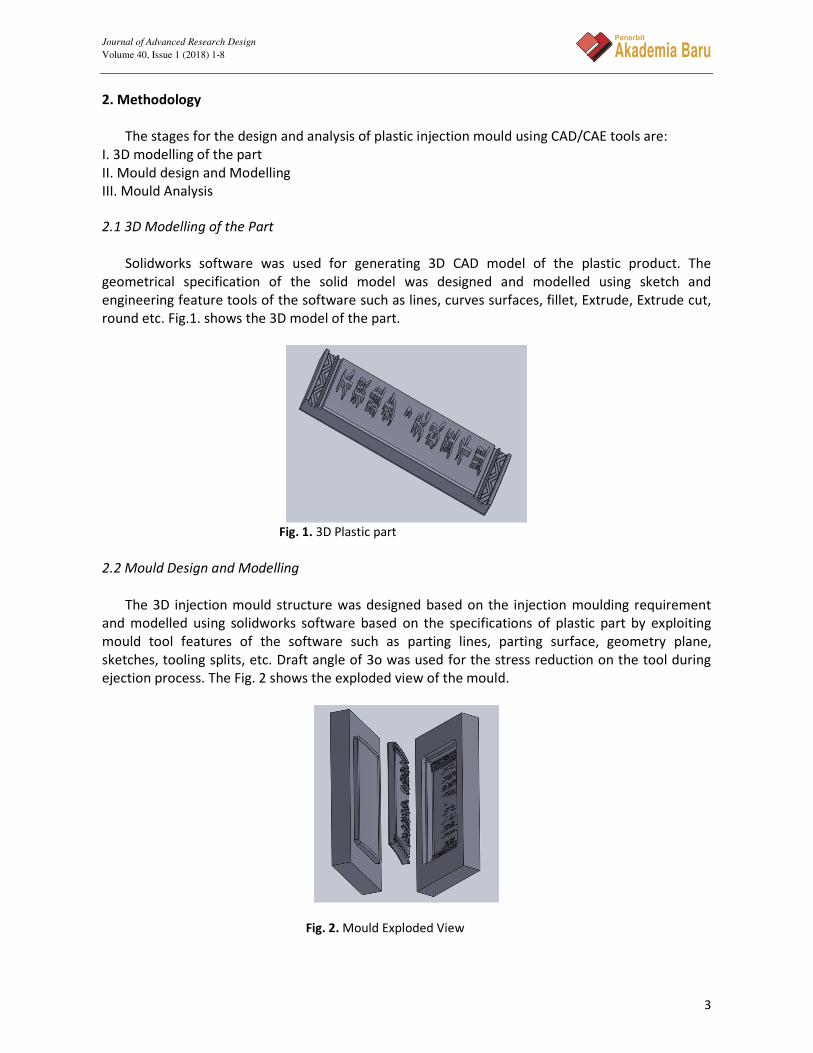
2.1 3D Modelling of the Part
Solidworks software was used for generating 3D CAD model of the plastic product. The
geometrical specification of the solid model was designed and modelled using sketch and
engineering feature tools of the software such as lines, curves surfaces, fillet, Extrude, Extrude cut,
round etc. Fig.1. shows the 3D model of the part.
Fig. 1. 3D Plastic part
2.2 Mould Design and Modelling
The 3D injection mould structure was designed based on the injection moulding requirement
and modelled using solidworks software based on the specifications of plastic part by exploiting
mould tool features of the software such as parting lines, parting surface, geometry plane,
sketches, tooling splits, etc. Draft angle of 3o was used for the stress reduction on the tool during
ejection process. The Fig. 2 shows the exploded view of the mould.
Fig. 2. Mould Exploded View

Journal of Advanced Research Design
Volume 40, Issue 1 (2018) 1-8
4
Penerbit
Akademia Baru
2.3 Mould Analysis
The data file of the 3D Mould cavity was transferred as parasolid file format to the CAE module
for analysis. The mould cavity was subjected to thermal analysis for analyzing the amount of heat
induced in the mould during the injection process and structural analysis for analyzing the stresses
induced in the mould using ANSYS software.
2.3.1 Mould meshing
The injection mould was meshed in to a finite number of elements and nodes as shown in Fig.3.
Fig. 3. Mould meshing
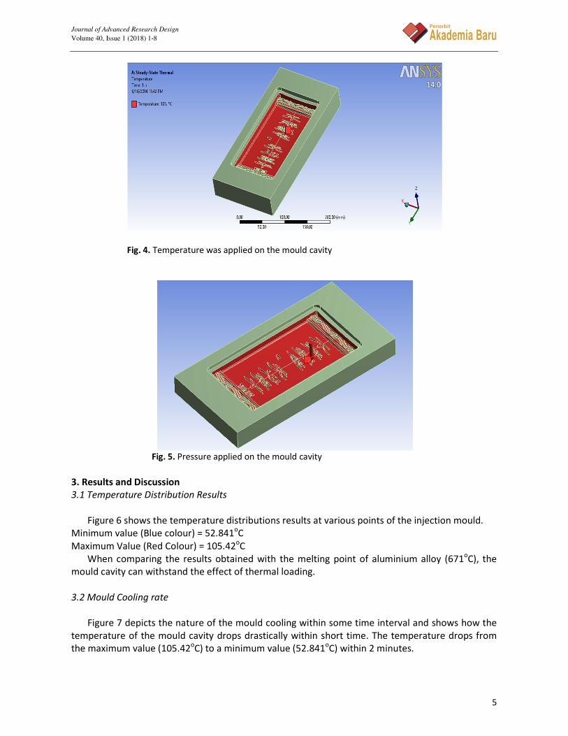
2.3.2 Thermal analysis
The mould cavity was subjected to a designated thermal loading at a temperature of 105oC
which is the temperature of molten plastics for determining the heat distributions in the mould.
Fig.4 shows how the temperature was applied on the mould cavity
Steps; Model > Steady-State Thermal > Loads >Temperature
2.3.3 Structural analysis
In structural analysis, the temperature distribution results were coupled with structural loading
of the mould cavity which was rigidly fixed at the designated edges and analyzed to determine
deformation, strain and stress due to thermal expansion. The working injection pressure is between
6.9 to 13.8MPa (1000 to 2000psi). A fixed support was applied at the bottom of the mould and
pressure of 13.8MPa was applied normal to the surface of the injection mould’s cavity as shown in
Fig.5.
Steps; Model > Static Structural > Load >Pressure
Journal of Advanced Research Design
Volume 40, Issue 1 (2018) 1-8
5
Penerbit
Akademia Baru
Fig. 4. Temperature was applied on the mould cavity
Fig. 5. Pressure applied on the mould cavity
3. Results and Discussion
3.1 Temperature Distribution Results
Figure 6 shows the temperature distributions results at various points of the injection mould.
Minimum value (Blue colour) = 52.841oC
Maximum Value (Red Colour) = 105.42oC
When comparing the results obtained with the melting point of aluminium alloy (671oC), the
mould cavity can withstand the effect of thermal loading.
3.2 Mould Cooling rate
Figure 7 depicts the nature of the mould cooling within some time interval and shows how the
temperature of the mould cavity drops drastically within short time. The temperature drops from
the maximum value (105.42oC) to a minimum value (52.841
oC) within 2 minutes.

Journal of Advanced Research Design
Volume 40, Issue 1 (2018) 1-8
6
Penerbit
Akademia Baru
Fig. 6. Temperature distribution of the mould cavity
Fig. 7. Temperature (oC) against time (s)
3.2 Deformation Results
The deformation results were obtained and showed in Fig. 8.
Minimum value (Blue colour) = 0mm
Maximum Value (Red Colour) = 0.012282 mm
Fig. 8. The deformation of mould cavity

Journal of Advanced Research Design
Volume 40, Issue 1 (2018) 1-8
7
Penerbit
Akademia Baru
When comparing the results with the mould dimensions (300x150x40mm), the value of the
maximum deformation (0.012282mm) is too small for about 0.03% of the mould dimension.
Therefore the effect of deformation can be neglected and the cavity has sufficient stiffness and
intensity to bear pressure of high-temperature melt there by increasing the accuracy of the plastic
product.
3.3 Von-Misses Elastic Strain Results
Figure 9 shows equivalent elastic strain results.
Minimum value (Blue colour) = 6.5735e-007
Maximum Value (Red Colour) = 8.8966e-004
Comparing the results obtained with the dimensions of the injection mould (300x150x40mm),
the results are far less than the mould dimensions (i.e. about 0.002% of the mould dimension),
therefore the effect of strain can be neglected and the mould has sufficient strength to withstand
the effect of thermal and structural loading during the injection process.
Fig. 9. The equivalent elastic strain of cavity
3.4 Elastic Stress Results
Figure 10 shows elastic stress results.
Minimum value (Blue colour) = 3.1394e-002MPa
Maximum Value (Red Colour) = 61.26MPa
For a safe and reliable design, the values obtained have to be tested using factor of safety. The
factor of safety describes the structural capacity of a system beyond the expected loads or actual
loads and must be greater than one (i.e. k>1) for a reliable design.
Therefore, the ultimate tensile strength of Aluminium alloy=310MPa
The result obtained for the maximum von-mises elastic stress=61.26MPa
Hence, Factor of Safety (k) = 5.
From the calculated result, the factor of Safety was found to be approximately five which
showed that the mould cavity has sufficient strength to withstand the effect of thermal and
structural loading.

Journal of Advanced Research Design
Volume 40, Issue 1 (2018) 1-8
8
Penerbit
Akademia Baru
Fig. 10. The equivalent elastic stress of cavity
The Thermal-Structural Analysis results are summarized in Table 1.
Table 1
Analysis Results
S/N Thermal-structural Analysis Minimum Value Maximum Value
1 Temperature distribution (oC) 52.841 105.42
2 Total deformation (mm) 0.00000 0.012282
3 Equivalent elastic strain (mm/mm) 6.5735e-007 8.8966e-004
4 Equivalent von-mises stress (MPa) 0.031394 61.26
4. Conclusion
In this paper, process design and analysis of plastic injection mould by means of CAD/CAE
softwares were presented. The results showed that integrated CAD/CAE system was an excellent
approach for designing and analyzing mould defects which proves to be a confident software tools.
Also the results showed that, with optimum utilization of CAD/CAE integrated technology can
improve quality of design, manufacture and Process capabilities of the injection moulding
industries. The period of product development and material consumption were also shortened.
References [1] Parag G., Chavhan."Injection Mold Development Using Unigraphics as CAD Software for Mass Scale Production of
a Plastic Container." International Journal of Latest Trends in Engineering and Technology (IJLTET) Vol. 5 Issue 2
March 2015.
[2] Saifullah, A. B. M., S. H. Masood, and I. Sbarski. "Thermal–structural analysis of bi-metallic conformal cooling for
injection moulds." The International Journal of Advanced Manufacturing Technology 62, no. 1-4 (2012): 123-133.
[3] Adhikari, Mukunda. "Natural fibre composites for injection moulding." (2012).
[4] Matin, I., M. Hadžistevic, J. Hodolič, Dj Vukelić, and B. Tadić. "Development of CAD/CAE System for Mold
Design." Journal of Production Engineering 13, no. 1 (2010): 61-64.
[5] Wong, C. T., Shamsuddin Sulaiman, Napsiah Ismail, and A. M. S. Hamouda. "Design and Simulation of Plastic
Injection Moulding Process." Pertanika J. Sci. & Technol. Supplement12, no. 2 (2004): 85-99.
[6] Wang Tianming and Jin Ye. "Rapid prototyping technology overview and current research focus [J]."Aeronautical
Manufacturing Technology, 2005, (6): 61.
[7] Lain. "CAD/CAM and Advanced Molding Industry." National Engineering Research center of die and mold CAD,
China, 2013.
[8] Saleh Amaitik "Computer integrated manufacturing (CIM)."ATILIM UNIVERSITY, 2006.
Journal of Advanced Research Design
Volume 40, Issue 1 (2018) 1-8
9
Penerbit
Akademia Baru
[9] Xu, X. W., and Q. Shi. "Plastics forming processes and the applications of CAD/CAM technology." Transactions of
the Institution of Professional Engineers New Zealand: Electrical/Mechanical/Chemical Engineering Section 26,
no. 1 (1999): 33.
[10] Pratt, Michael J. "Virtual prototypes and product models in mechanical engineering." In Virtual Prototyping, pp.
113-128. Springer, Boston, MA, 1995.
[11] Li Qun and Xiaoxiang Zhi. "Die CAD/CAE/CAM overview of the development and trends [J]." Mold Industry, 2005,
(07): 58.
[12] Mustapha M.U, Abdulrahaman S.A and Nuhu A.S. "Application of CAD/CAM Tools in the Production of
investment Casting Part." IOSR Journal of Mechanical and Civil Engineering (IOSR-JMCE) Volume 13, Issue 1 (Jan.
- Feb. 2016), PP 38-40.
[13] Zhou, Jian, and Tao Jing. "Integration of CAD/CAE system for casting process design." Tsinghua Science and
Technology 8, no. 1 (2003): 117-120.
[14] Zhou, Huamin, Songxin Shi, and Bin Ma. "A virtual injection molding system based on numerical simulation." The
International Journal of Advanced Manufacturing Technology40, no. 3-4 (2009): 297-306.
[15] Matin, Ivan, Miodrag Hadzistevic, Janko Hodolic, Djordje Vukelic, and Dejan Lukic. "A CAD/CAE-integrated
injection mold design system for plastic products." The International Journal of Advanced Manufacturing
Technology 63, no. 5-8 (2012): 595-607
[16] Hesham Ahmed, Faieza Binti, Rosaliza Hasan. " Review of Augmented Reality Applications in Manufacturing
Engineering.” Journal of Advanced Research in Computing and Applications 5, no. 1 (2016): 11-16.
[17] M.N. Rashidi, R. Ara Begum, M. Mokhtar and J.J Pereira. " Pelaksanaan Analisis Kandungan Sebagai Metodologi
Kajian bagi Mengenalpasti Kriteria Pembinaan Lestari .” Journal of Advanced Research Design 1, no. 1 (2014): 18-
27.