plasma-enhanced copolymerization of amino acid and...
TRANSCRIPT

Plasma-Enhanced Copolymerization of Amino Acid and SyntheticMonomersKyle D. Anderson,† Seth L. Young,† Hao Jiang,‡ Rachel Jakubiak,‡ Timothy J. Bunning,‡ Rajesh R. Naik,‡
and Vladimir V. Tsukruk*,†
†School of Materials Science and Engineering, Georgia Institute of Technology, Atlanta, Georgia 30332, United States‡Materials and Manufacturing Directorate, Air Force Research Laboratory, Wright-Patterson Air Force Base, Dayton, Ohio45433-7702, United States
ABSTRACT: In this paper we report the use of plasma-enhanced chemical vapor deposition(PECVD) for the simultaneous deposition and copolymerization of an amino acid with otherorganic and inorganic monomers. We investigate the fundamental effects of plasma-enhanced copolymerization on different material chemistries in stable ultrathin coatings ofmixed composition with an amino acid component. This study serves to determine thefeasibility of a direct, facile method for integrating biocompatible/active materials into robustpolymerized coatings with the ability to plasma copolymerize a biological molecule (L-tyrosine) with different synthetic materials in a dry, one-step process to form ultrathincoatings of mixed composition. This process may lead to a method of interfacing biologicsystems with synthetic materials as a way to enhance the biomaterial−tissue interface andpreserve biological activity within composite films.
■ INTRODUCTIONChemical vapor deposition (CVD) methods have been widelyused to polymerize materials directly on a variety of surfaces.1−4
CVD processes have been designed to allow organic monomersto undergo in situ polymerization during the depositionprocess, resulting in a stable film of polymerized material onthe surface. Polymerization is initiated by a range of differentstimuli, including radio frequency (rf) plasma radicalization,oxidation, and injection of an initiator into the reactionchamber.5−12 Each deposition method has the effect of creatinga polymerized film on a target substrate with different variationsin the cross-linking density and morphology depending on theCVD method used and the reaction mechanisms.13 This leadsto films with a wide range of unique surface properties that canbe tailored for many specialized applications.Plasma-enhanced chemical vapor deposition (PECVD) is a
specific form of CVD which has been adapted from its commonuse to deposit dielectrics to successfully deposit a wide range ofmonomers covering many traditional polymers, ranging fromstyrene, acrylonitrile, and benzene to responsive materials suchas poly(2-vinylpyridine) and poly(N-isopropylacrylamide) tofunctional amino acids.14−22 PECVD represents a versatile“dry” chemistry fabrication method which is capable of utilizingprecursors in solid, liquid, or gas form for facile, rapid, andsolvent-free fabrication of ultrathin coatings for use in manysystems.23−26 There is a growing interest in the deposition ofbiological molecules via PECVD, which can potentially be usedto enhance surface functionalities and structures for cellviability and can also help to bridge the interface betweeninorganic and biologic components of integrated systems andbiomedical applications.3,27−31
Biological monomers of interest are oftentimes in the form ofa powdery solid, presenting a unique set of challenges forplasma depositions of these monomers. Some solid monomerscan be deposited through various sublimation methodswhereby the monomers are preheated in the plasma chamberwhile under vacuum and vaporized into a gas phase.32−36 Thereaction proceeds akin to any gas-phase monomer. It has beendemonstrated that sublimation PECVD is compatible with arange of materials, from organometallics to amino acids,providing robust and stable films.18,19,32,33 The utilization ofsublimation allows solid materials which are not easilyvaporized to be plasma deposited, opening a new range ofsolid material precursors for study.Amino acids might be deposited via sublimation PECVD and
are excellent candidates for further investigation on the basis oftheir unique functionalities and fundamental biologic character-istics.18,19,37,38 In a recent study, Lee and Frank demonstratedvapor deposition of a wide range of amino acids which werefirmly grafted to a substrate and preserved their compositionand functionalities.30 PECVD lends itself well to copolymeriza-tions of two or more chemical species to facilitate complex andstable functionalized mixed coatings. However, this adds a layerof complexity to the deposition process given the differentreactivities of the precursors used. For instance, copolymeriza-tion has been previously reported using benzene andoctafluorocyclobutane (liquid and gaseous) monomers which
Received: November 9, 2011Revised: December 11, 2011Published: December 16, 2011
Article
pubs.acs.org/Langmuir
© 2011 American Chemical Society 1833 dx.doi.org/10.1021/la204416h | Langmuir 2012, 28, 1833−1845
are copolymerized in the plasma simultaneously to fabricatefilms with controllable refractive indices.39
One challenge with this fabrication process though isdetermining the appropriate deposition conditions whichallow a controlled reaction of different organic materialssimultaneously. This challenge is magnified when using onemonomer which is solid and must be sublimed into the plasmastream since flow rates are not as easily controlled as they arewith conventional liquid- and gas-phase monomers. In thisregard the deposition rates of each material must be matchedon the basis of the desired end ratio of the final filmcomposition. As the monomers are mixed in the plasma stream,they form highly randomized structures which when depositedexhibit characteristics of both components.39,40 Despite theutility of the sublimation PECVD procedure of biologicalmolecules, examples of robust and uniform binary plasma-polymerized films utilizing them are very rare. Developing thecapability of simultaneous depositions with different mono-mers, including bioactive compounds, of any important materialhighlights the versatility offered to the composition of theresulting plasma-polymerized films.In this study, we demonstrate the PECVD copolymerization
of the sublimed amino acid (L-tyrosine) with vaporized liquidmonomers, which results in stable and uniform ultrathincoatings with unique surface morphologies and characteristics.PECVD copolymerization of L-tyrosine (Tyr) was carried outwith several different monomers such as acrylonitrile, (ACN),2-hydroxyethyl methacrylate (HEMA), and titanium tetraiso-propoxide (TTIP). The organic and inorganic functionalmonomers used were chosen to demonstrate the feasibility ofthe integration of an amino acid with other synthetic materialswhich have been extensively studied to date. The amino acid L-tyrosine was chosen for this study due to important bioactivefunction in peptides, the expected compatibility withsublimation PECVD, and the well-understood plasma deposi-tion parameters.18,37 It is hoped that L-tyrosine provides insightinto the copolymerization of biologic molecules with othermaterials for many biointerfacial applications.3 A single aminoacid is used in this study with the intention of further expandingthe forthcoming study to other amino acids and eventuallylonger sequence peptide chains.ACN was utilized due to its compatibility with our plasma
deposition process. Many previous studies have evaluated thispolymer and its deposition characteristics.9,41,42 This factallowed the focus of this deposition to be centered oncontrolling the tyrosine deposition rate for proper materialmixing in the plasma. HEMA is an example of a material whichhas been previously characterized and demonstrated asbiologically compatible with its use in implants.43,44 Previousstudies have further characterized CVD HEMA as a swellablematerial.16,17,45,46 Any future integration of biological materialsto form composite films must include a second componentwhich has been well characterized and is understood to bebiologically compatible, such as HEMA.47
In this study HEMA serves as a biocompatible material forcopolymerization as it has been previously combined withtyrosine through radicalization via peroxide and UV polymer-ization.48 Finally, titanium tetraisopropoxide was used since itprovides a facile method of introducing an inorganiccomponent to the amino acid films. Creating such an interfaceon the nano- to microscale in this manner makes it a potentiallyuseful interface, which more easily allows the integration ofimplants with biological systems. The different materials
selected here were simultaneously reacted during the plasmadeposition to (a) determine their ability to form ultrathinstable, robust, uniform coatings with chemically mixedcomposition and (b) determine the copolymerization charac-teristics of biologic molecules with organic and inorganicmaterials for fabrication of bioactive plasma-polymerizedcoatings.
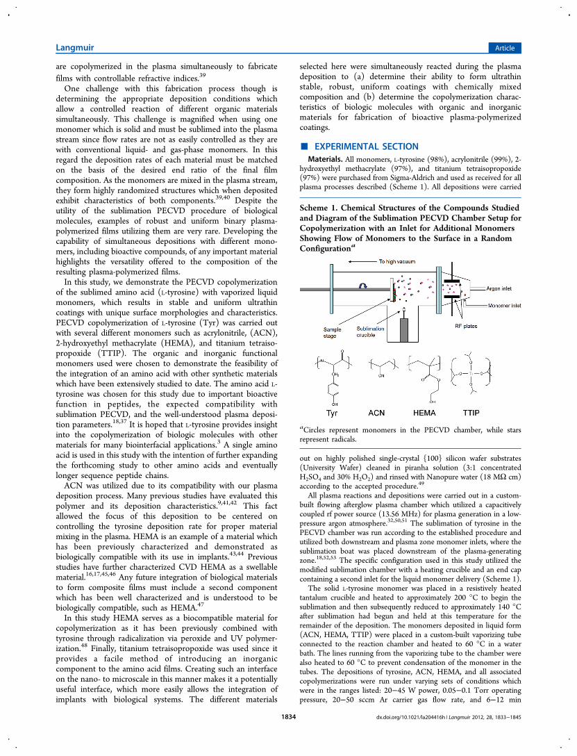
■ EXPERIMENTAL SECTIONMaterials. All monomers, L-tyrosine (98%), acrylonitrile (99%), 2-
hydroxyethyl methacrylate (97%), and titanium tetraisopropoxide(97%) were purchased from Sigma-Aldrich and used as received for allplasma processes described (Scheme 1). All depositions were carried
out on highly polished single-crystal {100} silicon wafer substrates(University Wafer) cleaned in piranha solution (3:1 concentratedH2SO4 and 30% H2O2) and rinsed with Nanopure water (18 MΩ cm)according to the accepted procedure.49
All plasma reactions and depositions were carried out in a custom-built flowing afterglow plasma chamber which utilized a capacitivelycoupled rf power source (13.56 MHz) for plasma generation in a low-pressure argon atmosphere.32,50,51 The sublimation of tyrosine in thePECVD chamber was run according to the established procedure andutilized both downstream and plasma zone monomer inlets, where thesublimation boat was placed downstream of the plasma-generatingzone.18,52,53 The specific configuration used in this study utilized themodified sublimation chamber with a heating crucible and an end capcontaining a second inlet for the liquid monomer delivery (Scheme 1).
The solid L-tyrosine monomer was placed in a resistively heatedtantalum crucible and heated to approximately 200 °C to begin thesublimation and then subsequently reduced to approximately 140 °Cafter sublimation had begun and held at this temperature for theremainder of the deposition. The monomers deposited in liquid form(ACN, HEMA, TTIP) were placed in a custom-built vaporizing tubeconnected to the reaction chamber and heated to 60 °C in a waterbath. The lines running from the vaporizing tube to the chamber werealso heated to 60 °C to prevent condensation of the monomer in thetubes. The depositions of tyrosine, ACN, HEMA, and all associatedcopolymerizations were run under varying sets of conditions whichwere in the ranges listed: 20−45 W power, 0.05−0.1 Torr operatingpressure, 20−50 sccm Ar carrier gas flow rate, and 6−12 min
Scheme 1. Chemical Structures of the Compounds Studiedand Diagram of the Sublimation PECVD Chamber Setup forCopolymerization with an Inlet for Additional MonomersShowing Flow of Monomers to the Surface in a RandomConfigurationa
aCircles represent monomers in the PECVD chamber, while starsrepresent radicals.
Langmuir Article
dx.doi.org/10.1021/la204416h | Langmuir 2012, 28, 1833−18451834

deposition time. The variation in conditions allowed for control of thecross-linking density of the film.54 The TTIP depositions were rununder identical conditions with the addition of an oxygen carrier gas at20−50 sccm instead of argon. This was used for both the pure PP-TTIP and PP-Tyr/TTIP films. After the plasma-enhanced deposition,the films were removed from the chamber and allowed to rest for aminimum of 48 h before further modification or analysis to allow allinternal stresses to equilibrate.Characterization. Atomic force microscopy (AFM) images were
collected using an Icon AFM microscope with a Nanoscope Vcontroller (Bruker) under the quantitative nanomechanical mapping(QNM) regime in air.55 Triangle ScanAsyst-Air cantilevers (Bruker)with a nominal spring constant of 0.4 N m−1 were used for allmeasurements. Scan sizes from 20 μm to 500 nm were collected at anoptimized scan rate of 1 Hz. The surface distribution of relativemechanical properties was collected in the peak-force mode, and theDerjaguin−Muller−Toropov (DMT) model was used to calculate theelastic modulus.56,57 All surface (rms) microroughness measurementswere conducted over six 1 × 1 μm2 area and averaged over severalsurface locations.Surface compositions were obtained with X-ray photoelectron
spectroscopy (XPS) using a Thermo K-Alpha XPS system with an AlKα source and utilizing charge neutralization. The initial spectra werecollected over the range of 0−1300 at 1 eV steps with a spot size of300 μm averaged over two scans. High-resolution scans wereperformed in the range of relevance for specific elements at 0.1 eVsteps and averaged over five scans. Energy-dispersive spectroscopy(EDS) was performed with an Oxford system on a Hitachi S-3400scanning electron microscope.Fourier transform infrared (FTIR) spectroscopy measurements
were conducted using a Bruker FTIR spectrometer (Vertex 70)equipped with a narrow-band mercury cadmium telluride detector inreflection mode.58 Spectra were collected from 4000 to 500 cm−1 at 1cm−1 resolution, and 16 scans were averaged. All thickness and opticalmeasurements were performed using an M-2000U variable-anglespectroscopic ellipsometer (Woollam Co.) with measurements at 65°,70°, and 75° and a spectral range from 350 to 1000 nm. All modelingof ellipsometric data was done using a Cauchy model in accordancewith the usual practice.59 Contact angle measurements were collectedusing a KSV CAM 100 system and placing a 2 μL drop on the surface.
■ RESULTS AND DISCUSSIONSingle-Material Depositions. Prior to beginning copoly-
merization PECVD experiments, each monomer was depositedand characterized independently to evaluate the quality of theultrathin films formed. All monomers were deposited on cleansilicon substrates and characterized by AFM to determine themorphology of the PECVD films and the mechanical stabilityof each coating. All films were deposited to a thickness ofbetween 200 and 300 nm as measured by spectroscopicellipsometry and were characterized with FTIR and XPS todetermine the composition in addition to AFM. Significantdifferences were noted in the morphology among the fourmaterials evaluated here.AFM imaging shows the resulting depositions of all materials
on clean silicon surfaces (Figures 1 and 2). The dry L-tyrosine(PP-Tyr) powder was sublimed for deposition (Figures 1A and2A). The liquid acrylonitrile (PP-ACN) monomer wasdeposited by the standard vaporization method (Figures 1Band 2B), and the liquid HEMA (PP-HEMA) monomer washeated to 60 °C and deposited as a standard vapor deposition(Figures 1C and 2C). Large-scale AFM images show veryuniform surface morphology of all films, indicating highlyhomogeneous composition with low surface microroughness,which is indicative of uniform cross-linking and wetting of thedeposits of all components. These films are free of pinholedefects as well. This observation is in good agreement with
previous studies of tyrosine and published literature regardingHEMA.16,18 The surface microroughness of each sample wasmeasured to be 0.6, 0.3, and 0.4 nm for PP-Tyr, PP-ACN, andPP-HEMA, respectively, which correspond to values usuallyreported for PECVD films in the literature for differentmaterials.60 These values correlate well with our previous datafor microroughness for the various polymer and amino acidfilms obtained via PECVD.18,41
Corresponding high-magnification AFM images show thedifferences in the fine morphologies of the plasma-polymerizedfilms of each coating (Figure 2). The PP-Tyr film shows adistinctive morphology composed of many small, distinctneedle-like domain structures (∼50−100 nm in length anddiameter below 10 nm) which differs from the more uniformtexture features of PP-ACN and PP-HEMA films where thedimensions of isolated round grains are within 20−50 nm. ThePP-Tyr structure becomes clearly evident under the highestresolution scanning (300 nm × 300 nm), where it is observedthat the domains are in fact individual tubular structures inrandom orientations on the surface (Figure 2A, right image).Three organic films show significant differences in morphology,structure, and roughness when compared to the much rougher
Figure 1. AFM images of (A) PP-Tyr, (B) PP-ACN, (C) PP-HEMA,and (D) PP-TTIP coatings. The left images show the topography(z(A,B,C) = 4 nm, z(D) = 24 nm), and the right images show therelative surface stiffness (arbitrary z scales).
Langmuir Article
dx.doi.org/10.1021/la204416h | Langmuir 2012, 28, 1833−18451835

PP-TTIP inorganic coating. These distinctions in filmmorphology are important to note, as they govern propertiessuch as microroughness and show that each material willdeposit in a unique manner, even under similar depositionconditions.The PP-TTIP film was deposited in an oxygen-rich
atmosphere as a homogeneous film on a larger scale andshowed a characteristically coarse grainy surface with a highporosity composed of aggregated and coarser features with
cluster dimensions above 40 nm which are composed of 10−20nm round grains (Figure 2D). Such morphology results fromthe plasma deposition in the presence of oxygen as previouslyreported.61,62 According to previous studies, the resultingporous surface is a product of the deposition in an oxygen-richenvironment in which the titanium atom of the TTIP willcompletely radicalize to a Ti4+ state. This is in contrast to thepartial radicalization (Ti3+) which occurs in a pure argonenvironment and is resistant to complete oxidation uponremoval from the vacuum.36,63,64 The surface microroughnessof the pure titania film was measured at 3.6 nm, which is muchlarger than that measured for the organic and biological plasma-deposited films and larger than that of a PP-TTIP filmdeposited under an argon atmosphere. The oxygen-richdeposition was used as a method to promote the highestpossible valence state of the titanium atom, allowing for anincreased number of bonding sites for oxygen, which createstitania molecules with a 2:1 oxygen:titanium stoichiometry. Insome instances, the introduction of oxygen may provide anonideal deposition regime for the second material as oxidationcan occur. However, it was observed that the resultingcopolymerized films were stable when deposited with oxygenpresent in the chamber and were not significantly affected bythis change in the atmosphere.The AFM images of each of these materials show the
topography and the relative surface stiffness distribution (inrelative units) obtained from peak-force mode scanning(Figures 1 and 2).65 In addition to a smooth topography, allcoatings exhibit a uniform surface stiffness across the surfacewith very modest variation, indicating that there are no localsurface regions of dramatically different mechanical properties,and thus, a uniform distribution in cross-linking density of theplasma-deposited films can be suggested. When compared tothe traditional spin-cast films of the same materials (bothmonomer and polymer coatings), the plasma-deposited filmswere seen to be much more stable, have greater adhesion tosubstrates and were much more uniform, albeit ultrathincoatings.
Chemical Composition of Single-Material Films: FTIRStudies. The chemical composition of plasma-polymerizedfilms was evaluated from FTIR spectra with several character-istic peaks detectable for each monomer (Scheme 1, Table 1,Figure 3). The PP-Tyr film shows key absorption peaks around3200 cm−1, which corresponds to the O−H stretch, and around
Figure 2. High-resolution AFM images of (A) PP-Tyr, (B) PP-ACN,(C) PP-HEMA, and (D) PP-TTIP coatings: (left) topography(z(A,B,C) = 4 nm, z(D) = 24 nm), (center) relative surface stiffness(arbitrary z scales), (right) high-resolution topography (z = 4 nm (A),6 nm (B), 3 nm (C), and 24 nm (D)).
Table 1. Polymerized Films with the FTIR Peak Assignment
PP-TYR PP-ACN PP-HEMA PP-TTIP PP-TYR/ACN PP-TYR/HEMA PP-TYR/TTIP
NH stretch 3270 3263OH stretch 3208 3283 3256 3204 3200amine peak 3025 3024CH2 asymmetric stretch 2940 2970 2962 2935CH3 symmetric stretch 2873 2875CN stretch (cyano) 2215 2220CO stretch 1723 1725C−C stretch 1610 1675 1640 1628 1611 1611 1612C−C/C−H (ring) 1514 1515 1516 1515CH2 in-plane bending 1450 1459 1452 1456 1447C−C stretch 1332 1344 1331 1330 1330ring OH vibration 1257 1244 1247 1250NH2 backbone bending 829 840 839 857Ti−O 696 697
Langmuir Article
dx.doi.org/10.1021/la204416h | Langmuir 2012, 28, 1833−18451836

3000 cm−1, representing an amine peak (Figure 3A).66 Thepreservation of the ring structure during plasma-assistedpolymerization is confirmed by the presence of peaks at1610, 1514, and 1332 cm−1 which correspond to the intactaromatic ring C−C double and single bond vibrations.67 Thepeak seen at 1257 cm−1 confirms the presence of O−H groupsattached to the aromatic ring. The NH2 bending vibration peakoccurring at 829 cm−1 in the PP-Tyr film has been previouslyobserved to be a marker present in polytyrosine which shiftsduring cross-linking from an original position of 876 cm−1.18
This band is a key indicator of the cross-linking that isoccurring in the film as it is deposited.The FTIR spectrum for the PP-ACN film shows several
intense peaks indicative of a high degree of cross-linking (Table1, Figure 3B). The first is seen as a large, broad peak around3270 cm−1 present from the N−H stretching, and the second isthe CN stretching mode seen around 1675 cm−1 along withthe peak at 1092 cm−1 from C−N which results from the cyanogroup dissociation and cross-linking.41 The observed peaks ofCH2 stretching at 2940 cm
−1 and C−C stretching at 1450 cm−1
are also indicators of the preservation of backbones. The CNstretch seen around 2215 cm−1 is characteristic of the cyanogroup, indicating its presence in the plasma-deposited film.The PP-HEMA spectra exhibit several characteristic peaks,
including a broad O−H stretch around 3283 cm−1 and a COstretch at 1723 cm−1 (Figure 3C).45 Both of these groups areseen in the side structure, and their presence indicates that they
remained intact during the plasma deposition. Additional sidechain peaks also seen are a CH2 asymmetric stretch at 2970cm−1, a CH3 symmetric stretching at 2873 cm−1, CH2 in-planebending at 1459 cm−1, and C−O−C asymmetric and symmetricstretching vibrations at 1079 and 1037 cm−1. As indicated byPfluger et al., the absence of a peak in the range of 3060−3010cm−1 and at 1600 cm−1 indicates that no HCC structure ispresent in the PECVD film, indicating no residual monomer, asthis double bond structure is not expected in a polymerizedHEMA film. Also, the OH peak around 3300 cm−1 is expectedto be minimized with higher cross-linking, which is the case inthe sample measured, indicating that significant cross-linking isoccurring in the PP-HEMA film.46 This agreement of themeasured PP-HEMA films with established literature valuesprovides strong evidence of efficient polymerization occurringunder given plasma deposition conditions.16,68
Finally, the PP-TTIP film exhibited a characteristic Ti−Opeak near 700 cm−1 (Figure 3D). The peak seen is expected tocontain minimal contributions from the silicon substrate asthese peaks were carefully accounted for during the measure-ments and result primarily from the convolution of the Ti−Oand residual carbon peaks, indicating polymerization reactionsin accordance with known mechanisms.69 In this case additionalcarbon peaks are seen at 1628 and 1344 cm−1 that correspondto the CC and CH3 bending vibrations, respectively.63 TheO−H stretching peak at 3256 cm−1 is also consistent with thepredicted reaction products as well as a result of the silicon
Figure 3. ATR-FITR (ATR = attenuated total reflection) spectra from coatings: (A) PP-Tyr, (B) PP-ACN, (C) PP-HEMA, (D) PP-TTIP.
Langmuir Article
dx.doi.org/10.1021/la204416h | Langmuir 2012, 28, 1833−18451837

substrate used where surface hydroxylation occurs during thecleaning process. This spectrum confirms the presence of thetitania as well as expected byproduct from the dissociation ofthe TTIP monomer during the plasma deposition.Overall, the FTIR results discussed above confirm that the
PECVD coatings contain key chemical features intact and arenot structurally compromised. The data also indicate that chainformation and cross-linking are occurring among themonomers as they are deposited.Chemical Composition of Single-Material Films: XPS
Analysis. XPS analysis of the plasma-polymerized coatingsconfirms the expected compositions corresponding to theiroriginal chemical structures (Scheme 1, Table 2). PP-Tyr andPP-ACN showed the expected carbon, nitrogen, and oxygenpeaks, whereas PP-HEMA shows only the carbon and oxygenpeaks (Figure 4A−C, Table 2). The PP-TTIP film shows a
strong Ti peak as well as significant oxygen with some residualcarbon content in the film (Figure 4D). The residual carbon inthe PP-TTIP film results from the number of methyl groupsattached to the oxygen atoms which react to form a separatecarbon system that is deposited on the surface as detailedelsewhere.63
The measured compositions generally correspond well totheoretically calculated ones on the basis of the chemicalstructures of the monomers (Table 2). This correlationindicates that the plasma-deposited films are maintainingroughly the same atomic composition of the monomers, exceptfor a few cases, notably PP-HEMA, which shows an excess ofcarbon, likely resulting from surface carbon contaminationupon exposure to air. Both the PP-TTIP films show less carbonand more oxygen than expected, which is likely due to the lossof carbon as a byproduct of the deposition, which is aimed at
Table 2. Atomic Percentages of Key Elements from XPS Data
theoretical composition experimental results
compound/composition C O N Ti C1s O1s N1s Ti2p
Tyr 59.6 26.5 7.7 0.0 68.5 21.8 9.7 0.0ACN 67.8 0.0 26.4 0.0 71.0 13.5 12.8 0.0HEMA 55.3 36.9 0.0 0.0 77.6 22.4 0.0 0.0TTIP 50.7 22.5 0.0 16.9 34.1 48.2 2.0 15.9composite films
Tyr/ACN 61.5 20.5 12.0 0.0 69.6 21.2 7.5 0.0Tyr/HEMA 57.8 30.8 4.5 0.0 75.4 21.6 3.0 0.0Tyr/TTIP 54.1 24.1 3.0 10.3 69.2 22.9 6.8 0.0
Figure 4. XPS plots for (A) PP-Tyr, (B) PP-ACN, (C) PP-HEMA, and (D) PP-TTIP coatings.
Langmuir Article
dx.doi.org/10.1021/la204416h | Langmuir 2012, 28, 1833−18451838

capturing the titanium and oxygen on the surface. Since thisdeposition was done in an oxygen-rich plasma, contributions tothe oxygen content of the film could also be present from thissource as well as absorption from the atmosphere, as is likelythe case with PP-ACN.64
Copolymerizations of Different Compounds. The firstcopolymerization of L-tyrosine and ACN was carried out withsimultaneous use of the sublimation apparatus and vaporbubbler to introduce both materials to the plasma reactor. Carewas taken to match the deposition rates of the two materials tominimize nonuniformity of the mixed films deposited.Matching the deposition rates was done by first depositingPP-Tyr on a clean silicon wafer and measuring the thickness,giving a deposition rate calibration for a particular set ofconditions. These conditions were then verified for compati-bility with the second monomer, and an appropriate monomerflow rate for the second monomer was then calibrated so thatthe two monomers could be simultaneously deposited.At a large scale, the resulting composite films from two
different monomers are relatively smooth and defect free,showing relatively few features (Figure 5). There was an
increase seen in the surface microroughness compared to thatof the two single-material depositions. The microroughness wasmeasured at 1.4 nm, which represents a 3-fold increase overthat of the single-monomer films. Apparently, mixing twomonomers results in the cross-linked network having regionalvariations and a grainy morphology, which increases the overallroughness of the film. The typical surface feature size rangesfrom 5 to 10 nm in height and from approximately 10 to 50 nmlaterally, depending on the film composition. Overall the
surface stiffness remains relatively uniform on a large scale,confirming the absence of microscopic dewetting andaggregation.Next L-tyrosine and HEMA monomers were deposited onto
the silicon surface simultaneously while under an argonatmosphere. The deposition rates of L-tyrosine and HEMAwere matched so that the deposition occurred with a depositionrate of approximately 20 nm/min. Heating of the L-tyrosinemonomer was begun prior to engagement of the plasma so thatthe material would be subliming as soon as the plasma wasactivated and HEMA introduced into the system. Both theACN and the HEMA monomers deposited similarly to the L-tyrosine but produced dissimilar features in the final film.An interesting and distinct microstructure was observed in
the composite film that is not seen in either of the monomerfilms under high-resolution AFM imaging (Figure 6). The
surface stiffness distribution shows some inhomogeneitieswhich are also seen in the topography. These variations oftopographical features are measured to be less than 4 nm inheight and are only clear at the highest magnifications.Moreover, the PP-Tyr/ACN film shows tubular-like structuresvery similar to those observed for the PP-Tyr film but in amuch more diluted version. A distinctive morphology also seenin the PP-Tyr/HEMA film is reminiscent of the appearance of amicrophase-separated system at the nanoscale. There is adistinct lack of tubular-like PP-Tyr morphological structures inthe PP-Tyr/HEMA film that are seen in both PP-Tyr/TTIPand high-resolution PP-Tyr/ACN. A more uniform weaklyphase separated surface is seen in PP-Tyr/HEMA. Thecopolymerized PP-Tyr/HEMA film was seen to be defectfree with a measured surface microroughness of 0.8 nm, a smallincrease over that of the pure PP-HEMA film.
Figure 5. AFM images of copolymerized films: (A) PP-Tyr/ACN, (B)PP-Tyr/HEMA, (C) PP-Tyr/TTIP, (left) topographies A (z = 14nm), B (z = 8 nm), and C (z = 24 nm), (right) surface stiffness(arbitrary z scales).
Figure 6. High-resolution AFM images of composite films: (A) PP-Tyr/ACN, (B) PP-Tyr/HEMA, (C) PP-Tyr/TTIP, (left) top-ographies A (z = 14 nm), B (z = 8 nm), and C (z = 24 nm),(center) surface stiffness (arbitrary z scales), (right) high-resolutiontopography (z = 8 nm (A), 8 nm (B), and 16 nm (C)).
Langmuir Article
dx.doi.org/10.1021/la204416h | Langmuir 2012, 28, 1833−18451839

The final copolymerization study utilizing a liquid inorganiccomponent, titanium isopropoxide, and solid L-tyrosine wasconducted with the two monomers being vaporized andexposed to the plasma simultaneously. Titanium isopropoxidewas heated in a liquid state to facilitate vaporization, while L-tyrosine was sublimed in the same manner used for the single-monomer depositions. The combination of these two materialsshowed a highly unique microstructure consisting of largeneedle-like structures embedded in a uniform matrix, which hasnot been observed in any of our previous plasma depositionstudies (Figures 5C and 6C). These needle-like structures areprominently visible in the adhesion variation and are typicallymeasured to be 200−600 nm in length and 20−25 nm in height
as can be concluded from AFM cross-section images (Figure7). We suggest that these needle-like structures are composedof PP-Tyr structures which have grown to larger sizes ascompared to the nanoscale features seen on the PP-Tyr filmand reported in the literature.70,71 These studies suggest theformation of tubular structures based upon tyrosine is possibleunder vacuum deposition conditions and a similar phenomen-on may be occurring in our plasma deposition process.72 Thesestructures are likely seen on the surface of the film assublimation will continue for a short time after the heatingcrucible and plasma are switched off while the crucible cools.Tubular structures from amino acids are well documentedunder this type of physical vapor deposition and will cover the
Figure 7. AFM image showing (A) relative adhesion of the PP-Tyr/TTIP needle structures and (B) the topography cross-section (along the whiteline in (A)) detailing the height and width (nm) of the needles.
Figure 8. ATR-FTIR spectra of composite coatings: (A) PP-Tyr/ACN, (B) PP-Tyr/HEMA, (C) PP-Tyr/TTIP.
Langmuir Article
dx.doi.org/10.1021/la204416h | Langmuir 2012, 28, 1833−18451840

surface with pure tyrosine, masking the titanium signal whenevaluated via XPS. Any large-scale or repeated microphaseseparation in the system is unlikely due to the rapid step growthmechanisms of film formation in PECVD. When radicalizedspecies react, they will tend to do so randomly. Localinhomogeneities may well exist in the film as the plasmadeposition process is subject to a degree of monomer mixingand randomness during the deposition and a truly homoge-neous film would require perfect distribution of the vaporizedmonomers. Additionally, some radicals go unreacted and areheld in place through the cross-linked network which is formedand do not permeate from the film. This would imply that anyphase separation occurring after the deposition is unlikely.
In fact, these needle-like structures are dramatically differentin comparison to the reported titania structures depositedunder oxygen at 298 K.61 Previous studies have shown titaniastructures with the round and pitted features seen on our filmsby AFM (Figure 2 D). No needle-like, lateral features across thetop of the film were reported; only vertical features runningthough the depth of the deposited layer were of prominence. Inaddition, the surface stiffness map shows little to no relativechange in the mechanical properties of the features (Figure6C). This is an indication that while features are forming in thefilm during the deposition, they are of a homogenizedcomposition, and no stiffness contrast is observed as wouldbe expected for titania-based structures. Also, needle-like
Figure 9. XPS of composite coatings: (A) PP-Tyr/TTIP (inset, EDS spectrum). High-resolution XPS scan of the carbon region: (B) PP-Tyr andPP-ACN, (C) PP-Tyr and PP-HEMA, (D) PP-Tyr and PP-TTIP. (E) Representative plot showing peak deconvolutions of the PP-Tyr film.
Langmuir Article
dx.doi.org/10.1021/la204416h | Langmuir 2012, 28, 1833−18451841

structures show low adhesion when compared to the rest of thesurface, which should be expected for the crystal surface incomparison with the disorganized surrounding surface (Figure7A). Finally, the absence of a clear titanium signal in the XPSscan sensitive to the topmost 10 nm indicates that the uppersurface structures cannot be composed of TTIP monomers(see below).Chemical Composition of Composite Films: FTIR, XPS,
and Spectroscopic Ellipsometry. Common characteristicpeaks on FTIR spectra are seen for the composite films and thesingle material films (Table 1, Figure 8). PP-Tyr/ACN showedmajor absorption peaks from each monomer, including the CN stretch of the cyano group seen near 2220 cm−1 and thebroad O−H peak of tyrosine centered near 3200 cm−1
combined with broad amine peaks and C−H peaks near3000 and 2960 cm−1.41,66 Additional peaks correspond wellwith the remaining PP-Tyr peaks seen in the single-materialfilm, especially those of the aromatic ring at 1611 and 1515cm−1. The CN stretch seen in the PP-ACN film is stillpresent near 1675 cm−1, but is convoluted with the aromaticring peak of PP-Tyr and not readily visible. The PP-Tyr/HEMA composite film shows all of the characteristic FTIRpeaks of the PP-Tyr film in addition to the CO stretch seenin PP-HEMA at 1725 cm−1, which not seen in the PP-Tyr film.Peaks were also seen near 1160 cm−1 indicating C−O
bonding and 1079 and 1037 cm−1 for C−O−C asymmetric andsymmetric vibrations as well as near 1247 cm−1 for character-istic amide bonding. Previous studies of tyrosine/HEMAconjugations have reported radicalization of the −OH groupon the tyrosine via peroxide exposure, which served as anattachment site for HEMA, and show bonding characteristicssimilar to those observed here.48 This study was carried out ontyrosine exposed on a collagen surface and directly modifiedthrough peroxide exposure and surface radicalization to bond tofree HEMA monomer. The PP-Tyr/TTIP film is seen to retainthe Ti−O peak at 697 cm−1, indicating the presence of titania ifthe total thickness of the film is probed. This peak is shifted andsomewhat obscured from Si−C bonding occurring as thedeposited material bonds to the surface.All of the copolymerized films show peaks that are consistent
with both the tyrosine ring structure remaining intact and theselected marker peaks from the second component, indicatingthat copolymerization is occurring and resulting in a highlycross-linked film with a binary composition. This shift from theL-tyrosine position of 876 cm−1 is seen in all the compositefilms at 840, 839, and 857 cm−1 for PP-Tyr/ACN, PP-Tyr/HEMA, and PP-Tyr/TTIP, respectively. The PP-Tyr/TTIPpeak at 857 cm−1 is determined through deconvolution of asingle larger peak seen and represents our best estimate. All thepeak shifts of this NH2 peak in the copolymerized films are lessthan that of L-tyrosine to PP-Tyr, which indicates that themonomers are forming bonds near this position in themolecular structures. The shift shows that this is occurringbetween the two monomers and they are not solelypolymerizing as isolated monomers. It is noted that this NH2peak does not appear in the PP-ACN film and is a characteristicpeak of tyrosine. These results indicate the presence of tyrosine,and the consistent shift seen in the copolymerized films likelyresults from NH2 acting as a bonding site, leading to theconclusion that true copolymerization of the monomers isoccurring during the plasma deposition.XPS of the copolymerized films shows the expected
characteristic peaks of PP-Tyr/ACN, PP-Tyr/HEMA, and
PP-Tyr/TTIP with strong peaks of carbon, nitrogen, andoxygen as demonstrated in a representative observational XPSplot (Figure 9A). The atomic percentage distributions show theexpected elemental presence in the films and generallycorrespond with the theoretical predictions of the composition(Table 2). The theoretical atomic percentages were estimatedassuming a 1:1 ratio of the mixed monomers. While PP-Tyr/ACN and PP-Tyr/TTIP have values that are in generalagreement with the expected values for a 1:1 mixture, PP-Tyr/HEMA shows an increased carbon (and thus decreasedoxygen) content in the copolymerized film similar to that inthe homogeneous PP-HEMA film. The expected nitrogensignal from tyrosine is present in the PP-Tyr/HEMA film butnot in the PP-HEMA film, which indicates the presence of bothmonomers in the PP-Tyr/HEMA film. The excess carbon islikely carbon contamination which commonly occurs on asurface of active plasma-polymerized films.High-resolution XPS spectra of the carbon content in the PP-
Tyr/ACN and the PP-Tyr/HEMA films show a shift of thecarbon peaks consistent with combining the two monomers(Figure 9B,C). The primary peaks corresponding to C−C andC−H bonds are present in all single-material films.Deconvolution of all carbon peaks was performed to determinethe exact position of all peaks (see the example in Figure 9 E).The PP-Tyr/ACN film shows CO bonds (289.1 eV) notpresent in the PP-ACN film and a diluted presence of C−N(286.3 eV) with the addition of the C−C (284.5 eV) bondsfrom tyrosine.73 The same CO shoulder is seen in the PP-HEMA films (289.6 eV) as well and is expected on the basis ofits chemical structure. The PP-Tyr/TTIP XPS spectrum showsclear C−C, C−H (285.6 eV), and C−O (289.0 eV) peaks witha broadening of the primary peak from the addition of C−N(287.1 eV) containing tyrosine (Figure 9D). These resultsindicate that the original molecular carbon architecture remainsmainly intact during the plasma polymerization.The PP-Tyr/TTIP XPS scan shows the carbon, oxygen, and
nitrogen peaks as expected, but does not show a clear signatureof titanium. We suggest that this result indicates that the titaniais buried in the film and is not present at the surface. As known,a common XPS probing depth is around 10 nm for carbon-based materials.74 A titanium signal is clearly seen, however, ataround 4.5 keV in the EDS spectrum (Figure 9A, inset).Additional evidence of the presence of titanium is seen in bothFTIR and ellipsometry data. While the amount of titanium seenvia EDS is relatively small (∼2 atom %), it confirms thepresence of this element in the film, an indication that thecopolymerizations are occurring as described and corroboratingthe FTIR and ellipsometry assertions that titanium is present inthe films. The fact that a titanium presence is visible with EDSand FTIR is due to the fact that these techniques probe thecomposition of the entire film.As observed, the refractive indices of mixed films fall between
the two indices for the individual components as usuallyobserved for mixed films without significant heterogeneities(Figure 10).39,75 This refractive index can be adjusteddepending on the composition of the films by controlling thefeed rates of the monomers into the plasma, although this issomewhat more of a challenge to control with a sublimationprocess. The possibility of the refractive index changing ishighlighted in three different examples for the PP-Tyr/HEMAcomposite film, which shows a lower refractive index after theHEMA supply is increased (Figure 10B). The PP-Tyr/TTIPfilm clearly shows a higher refractive index than the PP-Tyr
Langmuir Article
dx.doi.org/10.1021/la204416h | Langmuir 2012, 28, 1833−18451842

film, but lower than that of the PP-TTIP film (Figure 10C).The change in refractive index to a higher value is a strongindication of the presence of titania and its role as an opticalmodifier of the films. It is worth noting that refractive indexvariation is an important feature which can be adapted to manyother plasma-deposited systems as well. Finally, all compositefilms exhibited a low absorption (k) value of less than 0.04 overthe visible spectra, indicating a relatively low light absorption,important for optical coatings.
While these data offer glimpses into the composition andstructure of the films, they are not the basis for a finalconclusion of the film structure. Further detailed chemicalanalysis to precisely determine the structure of the plasma-polymerized film could be done via techniques such as NMRand mass spectrometryy. This approach, however, has provendifficult for any polymerized ultrathin coatings (e.g., brushes)due to the insolubility of these coatings.
■ CONCLUSIONSWe have demonstrated that a selected amino acid, L-tyrosine, isable to be copolymerized with other synthetic organic andinorganic monomers via PECVD to form a stable and robustpartially cross-linked composite coating with fine morphologyformed by microphase-separated individual components whichto great extent preserve their individual chemical compositionand morphological features. Copolymerization of materials viasublimation PECVD demonstrates the ability to combinebiologic and nonbiologic molecules into a single uniformcoating of several hundred nanometers thickness in a rapid,facile, solventless, one-step procedure. This copolymerizationmethod can be used to form biologically active andbiofunctionalized robust coatings by adding amino acids andshort peptides for organic and inorganic matrixes. We believethat the amino acid used in this study can serve as a proxy forother biological molecules (such as short-chain peptides) whichcan potentially be copolymerized in a similar fashion with otherpolymers and inorganic materials to produce robust films withdesired compositions and enhanced surface functionality andcompatibility. Since the plasma polymerization fabricationapproach can be widely applied to many different surfaces,this technique has the potential to be applicable for designingenhanced biological interfaces.
■ AUTHOR INFORMATIONCorresponding Author*E-mail: [email protected].
■ ACKNOWLEDGMENTSThis work was supported by the Department of Defense(DoD) through the National Defense Science & EngineeringGraduate Fellowship (NDSEG) program. This research is alsosupported by the Air Force Office of Scientific Research(Grants FA9550-08-1-0446 and FA9550-09-1-0162), as well asthe Air Force Research Laboratory. We also thank R. BlakeWeber for technical assistance.
■ REFERENCES(1) Sreenivasan, R.; Gleason, K. K. Chem. Vap. Deposition 2009, 15,77−90.(2) Alf, M. E.; Asatekin, A.; Barr, M. C.; Baxamusa, S. H.; Chelawat,H.; Ozaydin-Ince, G.; Petruczok, C. D.; Sreenivasan, R.; Tenhaeff, W.E.; Trujillo, N. J.; Vaddiraju, S.; Xu, J.; Gleason, K. K. Adv. Mater.2010, 22, 1993−2027.(3) Forch, R.; Chifen, A. N.; Bousquet, A.; Khor, H. L.; Jungblut, M.;Chu, L.-Q.; Zhang, Z.; Osey-Mensah, I.; Sinner, E.-K.; Knoll, W. Chem.Vap. Deposition 2007, 13, 280−294.(4) Biederman, H. D. In Plasma Polymer Films; Biederman, H., Ed.;Imperial College Press: London, 2004; p 13.(5) Kuzuya, M.; Noguchi, A.; Ito, H.; Kondo, S.-I.; Noda, N. J. Polym.Sci., Part A: Polym. Chem. 1991, 29, 1−7.(6) Hess, D. W. J. Vac. Sci. Technol., A 1990, 8, 1677−1684.(7) Tenhaeff, W. E.; Gleason, K. K. Adv. Funct. Mater. 2008, 18,979−992.
Figure 10. Refractive index of (A) PP-Tyr/ACN, (B) PP-Tyr/HEMA,and (C) PP-Tyr/TTIP coatings.
Langmuir Article
dx.doi.org/10.1021/la204416h | Langmuir 2012, 28, 1833−18451843

(8) Friedrich, J.; Kuhn, G.; Mix, R. In Plasma Processes and Polymers;d’Agostino, R., Favia, P., Oehr, C., Wertheimer, M. R., Eds.; Wiley-VCH Verlag GmbH & Co. KGaA: Weinheim, Germany, 2005; p 10.(9) Yasuda, H. Plasma Polymerization; Academic Press Inc.: NewYork, 1985; p 6.(10) Im, S. G.; Gleason, K. K. AIChE J. 2011, 57, 276−285.(11) Lau, K. K. S.; Mao, Y.; Lewis, H. G. P.; Murthy, S. K.; Olsen, B.D.; Loo, L. S.; Gleason, K. K. Thin Solid Films 2006, 501, 211−215.(12) Karaman, M.; Kooi, S. E.; Gleason, K. K. Chem. Mater. 2008, 20,2262−2267.(13) Choukourov, A.; Biederman, H.; Slavinska, D.; Hanley, L.;Grinevich, A.; Boldyryeva, H.; Mackova, A. J. Phys. Chem. B 2005, 109,23086−23095.(14) Tamirisa, P. A.; Koskinen, J.; Hess, D. W. Thin Solid Films 2006,515, 2618−2624.(15) Tamirisa, P. T.; Hess, D. W. Macromolecules 2006, 39, 7092−9097.(16) Chan, K.; Gleason, K. K. Langmuir 2005, 21, 8930−8939.(17) Lopez, G. P.; Ratner, B. D. J. Polym. Sci., Part A: Polym. Chem.1992, 30, 2415−2425.(18) Anderson, K. D.; Slocik, J. M.; McConney, M. E.; Enlow, J. O.;Jakubiak, R.; Bunning, T. J.; Naik, R. R.; Tsukruk, V. V. Small 2009, 5,741−749.(19) Anderson, K. D.; Marczewski, K.; Singamaneni, S.; Slocik, J. M.;Naik, R. R.; Bunning, T. J.; Tsukruk, V. V. Appl. Mater. Int. 2010, 2,2269−2281.(20) Anderson, K. D.; Luo, M.; Jakubiak, R.; Naik, R. R.; Bunning, T.J.; Tsukruk, V. V. Chem. Mater. 2010, 22, 3259−3264.(21) Khan, H. U.; Roberts, M. E.; Johnson, O.; Forch, R.; Knoll, W.;Bao, Z. Adv. Mater. 2010, 22, 4452−4456.(22) Singamaneni, S.; McConney, M. E.; Tsukruk, V. V. Adv. Mater.2010, 22, 1263−1268.(23) LeMieux, M. C.; McConney, M. E.; Lin, Y.-H.; Singamaneni, S.;Jiang, H.; Bunning, T. J.; Tsukruk, V. V. Nano Lett. 2006, 6, 730−734.(24) Singamaneni, S.; LeMieux, M. C.; Lang, H. P.; Gerber, C.; Lam,Y.; Zauscher, S.; Datskos, P. G.; Lavrik, N. V.; Jiang, H.; Naik, R. R.;Bunning, T. J.; Tsukruk, V. V. Adv. Mater. 2008, 20, 653−680.(25) Pan, Y. V.; Wesley, R. A.; Luginbuhl, R.; Denton, D. D.; Ratner,B. D. Biomacromolecules 2001, 2, 32−36.(26) Johnson, E. M.; Clarson, S. J.; Jiang, H.; Su, W.; Grant, J. T.;Bunning, T. J. Polymer 2001, 42, 7215−7219.(27) Lahann, J. Polym. Int. 2006, 55, 1361−1370.(28) Chen, H.-Y.; Lahann, J. Langmuir 2011, 27, 34−48.(29) Slocik, J. M.; Beckel, E. R.; Jiang, H.; Enlow, J. O.; Zabinski, J. S.Jr.; Bunning, T. J.; Naik, R. R. Adv. Mater. 2006, 18, 2095−2100.(30) Lee, N. H.; Frank, C. W. Langmuir 2003, 19, 1295−1303.(31) Mari-Buye, N.; O’shaughnessy, S.; Colominas, C.; Semino, C.E.; Gleason, K. K.; Borros, S. Adv. Funct. Mater. 2009, 19, 1276−1286.(32) Enlow, J. O.; Jiang, H.; Grant, J. T.; Eyink, K.; Su, W.; Bunning,T. J. Polymer 2008, 49, 4042−4045.(33) Aparicio, F. J.; Holgado, M.; Borras, A.; Blaszczyk-Lezak, I.;Griol, A.; Barrios, C. A.; Casquel, R.; Sanza, F. J.; Sohlstrom, H.;Antelius, M.; Gonzalez-Elipe, A. R.; Barranco, A. Adv. Mater. 2011, 23,761−765.(34) Aparicio, F. J.; Borras, A.; Blaszczyk-Lezak, I.; Groning, P.;Alvarez-Herrero, A.; Fernandez-Rodríguez, M.; Gonzalez-Elipe, A. R.;Barranco, A. Plasma Processes Polym. 2009, 6, 17−26.(35) Blaszczyk-Lezak, I.; Aparicio, F. J.; Borras, A.; Barranco, A.;Alvarez-Herrero, A.; Fernandez-Rodríguez, M.; Gonzalez-Elipe, A. R. J.Phys. Chem. C 2009, 113, 431−438.(36) Barranco, A.; Groening, P. Langmuir 2006, 22, 6719−6722.(37) Singamaneni, S.; Kharlampieva, E.; Jang, J. H.; McConney, M.E.; Jiang, H.; Bunning, T. J.; Thomas, E. L.; Tsukruk, V. V. Adv. Mater.2010, 22, 1369−1373.(38) Dickerson, M. B.; Sandhage, K. H.; Naik, R. R. Chem. Rev. 2008,108, 4935−4978.(39) Jiang, H.; O’Neill, K.; Grant, J. T.; Tullis, S.; Eyink, K.; Johnson,W. E.; Fleitz, P.; Bunning, T. J. Chem. Mater. 2004, 16, 1292−1297.
(40) Jiang, H.; Eyink, K.; Grant, J. T.; Enlow, J.; Tullis, S.; Bunning,T. J. Chem. Vap. Deposition 2008, 14, 286−291.(41) Singamaneni, S.; LeMieux, M. C.; Jiang, H.; Bunning, T. J.;Tsukruk, V. V. Chem. Mater. 2007, 19, 129−131.(42) Singamaneni, S.; McConney, M. E.; LeMieux, M. C.; Jian, H.;Enlow, J. O.; Bunning, T. J.; Naik, R. R.; Tsukruk, V. V. Adv. Mater.2007, 19, 4248−4255.(43) Wichterle, O.; Lim, D. Nature 1960, 165, 117−118.(44) Jeyanthi, R.; Rao, K. P. Biomaterials 1990, 11, 238−243.(45) Pfluger, C. A.; Carrier, R. L.; Sun, B.; Ziemer, K. S.; Burkey, D.D. Macromol. Rapid Commun. 2009, 30, 126−132.(46) Bose, R. K.; Lau, K. K. S. Biomacromolecules 2010, 11, 2116−2122.(47) Quinn, C. P.; Pathak, C. P.; Heller, A.; Hubbell, J. A.Biomaterials 1995, 16, 389−396.(48) Wang, D.; Williams, C. G.; Yang, F.; Elisseeff, J. H. Adv. Funct.Mater. 2004, 14, 1152−1159.(49) Tsukruk, V. V.; Bliznyuk, V. N. Langmuir 1998, 14, 446−455.(50) Haaland, P.; Targove, J. Appl. Phys. Lett. 1992, 61, 34−36.(51) Jiang, H.; Johnson, W. E.; Grant, J. T.; Eyink, K.; Johnson, E. M;Tomlin, D. W.; Bunning, T. J. Chem. Mater. 2003, 15, 340−347.(52) Jiang, H.; Hong, L.; Venkatasubramanian, N.; Grant, J. T.;Eyink, K.; Wiacek, K.; Fries-Carr, S.; Enlow, J.; Bunning, T. J. ThinSolid Films 2007, 515, 3513−3520.(53) Jiang, H.; Grant, J. T.; Eyink, K.; Tullis, S.; Enlow, J.; Bunning,T. J. Polymer 2005, 46, 8178−8184.(54) Peri, S. R.; Habersberger, B.; Akgun, B.; Jiang, H.; Enlow, J.;Bunning, T. J.; Majkrzak, C. F.; Foster, M. D. Polymer 2010, 51, 4390−4397.(55) McConney, M. E.; Singamaneni, S.; Tsukruk, V. V. Polym. Rev.2010, 50, 235−286.(56) Pashley, M. D. Colloids Surf. 1984, 12, 69−77.(57) Pietrement, O.; Troyon, M. J. Colloid Interface Sci. 2000, 226,166−171.(58) Kharlampieva, E.; Slocik, J. M.; Singamaneni, S.; Poulsen, N.;Kroger, N.; Naik, R. R.; Tsukruk, V. V. Adv. Funct. Mater. 2009, 19,2303−2311.(59) Choi, I.; Suntivich, R.; Plamper, F. A.; Synatschke, C. V.; Muller,A. H. E.; Tsukruk, V. V. J. Am. Chem. Soc. 2011, 133, 9592−9606.(60) Peri, S. R.; Kim, H.; Akgun, B.; Enlow, J.; Jiang, H.; Bunning, T.J.; Li, X.; Foster, M. D. Polymer 2010, 51, 3971−3977.(61) Borras, A.; Cotrino, J.; Gonzalez-Elipe, A. R. J. Electrochem. Soc.2007, 154, 152−157.(62) Alvarez, R.; Romero-Gomez, P.; Gil-Rostra, J.; Cotrino, J.;Yubero, F.; Palmero, A.; Gonzalez-Elipe, A. R J. Appl. Phys. 2010, 108,064316.(63) Ahn, K.-H.; Park, Y.-B.; Park, D.-W. Surf. Coat. Technol. 2003,171, 198−204.(64) Jiang, H.; Grant, J. T.; Enlow, J.; Su, W.; Bunning, T. J. J. Mater.Chem. 2009, 19, 2234−2239.(65) Sweers, K.; van der Werf, K.; Bennink, M.; Subramaniam, V.Nanoscale Res. Lett. 2011, 6, 270.(66) Grace, L. I.; Cohen, R.; Dunn, T. M.; Lubman, D. M.; de Vries,M. S. J. Mol. Spectrosc. 2002, 215, 204−219.(67) Hernandez-Perez, M. A.; Garapon, C.; Champeaux, C.;Orlianges, J. C. J. Phys: Conf. Ser. 2007, 59, 724−727.(68) Tarducci, C.; Schofield, W. C. E.; Badyal, J. P. S; Brewer, S. A.;Willis, C. Chem. Mater. 2002, 14, 2541−2545.(69) Fictorie, C. P.; Evans, J. F.; Gladfelter, W. L. J. Vac. Sci. Technol.,A 1994, 12, 1108−1113.(70) Spear, R. L.; Tamayev, R.; Fath, K. R.; Banerjee, I. A. ColloidsSurf., B 2007, 60, 158−166.(71) Reches, M.; Gazit, E. Nat. Nanotechnol. 2006, 1, 195−200.(72) Adler-Abramovich, L.; Aronov, D.; Beker, P.; Yevnin, M.;Stempler, S.; Buzhansky, L.; Rosenman, G.; Gazit, E. Nat. Nanotechnol.2009, 4, 849−854.(73) Tsukruk, V. V.; Luzinov, I.; Julthongpiput, D. Langmuir 1999,15, 3029−3032.
Langmuir Article
dx.doi.org/10.1021/la204416h | Langmuir 2012, 28, 1833−18451844

(74) Luzinov, I.; Julthongpiput, D.; Liebmann-Vinson, A.; Cregger,T.; Foster, M. D.; Tsukruk, V. V. Langmuir 2000, 16, 504−516.(75) Grant, J. T.; Jiang, H.; Tullis, S.; Johnson, W. E.; Eyink, K.;Fleitz, P.; Bunning, T. J. Vacuum 2005, 80, 12−19.
Langmuir Article
dx.doi.org/10.1021/la204416h | Langmuir 2012, 28, 1833−18451845