plasma assisted combustion dynamics and chemistry
TRANSCRIPT
7/21/2019 Plasma Assisted Combustion Dynamics and Chemistry
http://slidepdf.com/reader/full/plasma-assisted-combustion-dynamics-and-chemistry 1/63
Review
Plasma assisted combustion: Dynamics and chemistry
Yiguang Ju a ,* , Wenting Sun b
a Department of Mechanical and Aerospace Engineering, Princeton University, NJ 08544, USAb School of Aerospace Engineering, Georgia Institute of Technology, GA 30332, USA
a r t i c l e i n f o
Article history:Received 14 July 2014Accepted 4 December 2014Available online
Keywords:Plasma assisted combustionCombustion enhancementChemistryDynamicsDiagnosticsNon-equilibrium plasmaKinetic model
a b s t r a c t
Plasma assisted combustion is a promising technology to improve engine performance, increase lean
burn
ame stability, reduce emissions, and enhance low temperature fuel oxidation and processing. Overthe last decade, signi cant progress has been made towards the applications of plasma in engines andthe understanding of the fundamental chemistry and dynamic processes in plasma assisted combustionvia the synergetic efforts in advanced diagnostics, combustion chemistry, ame theory, and kineticmodeling. New observations of plasma assisted ignition enhancement, ultra-lean combustion, cool
ames, ameless combustion, and controllability of plasma discharge have been reported. Advances aremade in the understanding of non-thermal and thermal enhancement effects, kinetic pathways of atomicO production, diagnostics of electronically and vibrationally excited species, plasma assisted combustionkinetics of sub-explosion limit ignition, plasma assisted low temperature combustion, ame regimetransition of the classical ignition S -curve, dynamics of the minimum ignition energy, and the transporteffect by non-equilibrium plasma discharge. These ndings and advances have provided new opportu-nities in the development of ef cient plasma discharges for practical applications and predictive, vali-dated kinetic models and modeling tools for plasma assisted combustion at low temperature and highpressure conditions. This article is to provide a comprehensive overview of the progress and the gap inthe knowledge of plasma assisted combustion in applications, chemistry, ignition and ame dynamics,experimental methods, diagnostics, kinetic modeling, and discharge control.
© 2014 Elsevier Ltd. All rights reserved.
Contents
1. Introduction . . . . . . . . . . . . . . . . . . . . . . . . . . . . . . . . . . . . . . . . . . . . . . . . . . . . . . . . . . . . . . . . . . . . . . . . . . . . . . . . . . . . . . . . . . . . . . . . . . . . . . . . . . . . . . . . . 1.1. Needs of combustion and emission control in extreme conditions . . . . . . . . . . . . . . . . . . . . . . . . . . . . . . . . . . . . . . . . . . . . . . . . . . . . . . . . . . . . . . . . . . . 11.2. Plasma assisted combustion: a new way to control combustion, emissions, and fuel reforming . . . . . . . . . . . . . . . . . . . . . . . . . . . . . . . . . . . . . . . . . . 21.3. Non-equilibrium plasma and the impact of plasma on combustion . . . . . . . . . . . . . . . . . . . . . . . . . . . . . . . . . . . . . . . . . . . . . . . . . . . . . . . . . . . . . . . . . . . 31.4. Progress and challenges in fundamental studies of plasma assisted combustion . . . . . . . . . . . . . . . . . . . . . . . . . . . . . . . . . . . . . . . . . . . . . . . . . . . . . . . . 41.5. Focus of this review . . . . . . . . . . . . . . . . . . . . . . . . . . . . . . . . . . . . . . . . . . . . . . . . . . . . . . . . . . . . . . . . . . . . . . . . . . . . . . . . . . . . . . . . . . . . . . . . . . . . .
2. Plasma assisted combustion: applications and technological development . . . . . . . . . . . . . . . . . . . . . . . . . . . . . . . . . . . . . . . . . . . . . . . . . . . . . . . . . . . . . . . . . 72.1. Plasma assisted combustion for supersonic propulsion and scramjet engines . . . . . . . . . . . . . . . . . . . . . . . . . . . . . . . . . . . . . . . . . . . . . . . . . . . . . . . . . . 72.2. Ignition enhancement by plasma in internal combustion engines . . . . . . . . . . . . . . . . . . . . . . . . . . . . . . . . . . . . . . . . . . . . . . . . . . . . . . . . . . . . . . . . . . . 102.3. Plasma assisted combustion for pulse detonation engines . . . . . . . . . . . . . . . . . . . . . . . . . . . . . . . . . . . . . . . . . . . . . . . . . . . . . . . . . . . . . . . . . . . . . . . . . 142.4. Plasma assisted combustion for flame stabilization in gas turbine engines . . . . . . . . . . . . . . . . . . . . . . . . . . . . . . . . . . . . . . . . . . . . . . . . . . . . . . . . . . . 142.5. Emission control and fuel reforming by plasma . . . . . . . . . . . . . . . . . . . . . . . . . . . . . . . . . . . . . . . . . . . . . . . . . . . . . . . . . . . . . . . . . . . . . . . . . . . . . . . . . .
3. Flame dynamics and chemistry in plasma assisted combustion . . . . . . . . . . . . . . . . . . . . . . . . . . . . . . . . . . . . . . . . . . . . . . . . . . . . . . . . . . . . . . . . . . . . . . . . . . 183.1. Dynamics and chemistry of plasma assisted ignition . . . . . . . . . . . . . . . . . . . . . . . . . . . . . . . . . . . . . . . . . . . . . . . . . . . . . . . . . . . . . . . . . . . . . . . . . . . . . 13.2. Dynamics, chemistry, and transport of plasma assisted flame propagation . . . . . . . . . . . . . . . . . . . . . . . . . . . . . . . .. . . . . . . . . . . . . . . . . . . . . . . . . . . . 203.3. Dynamics, chemistry, and transport of flame initiation and minimum ignition energy and the role of plasma discharge . . . . . . . . . . . . . . . . . . 223.4. Plasma assisted ignition by creating a large discharge volume . . . . . . . . . . . . . . . . . . . . . . . . . . . . . . . . . . . . . . . . . . . . . . . . . . . . . . . . . . . . . . . . . . . . . 23
* Corresponding author. Tel.: þ 1 609 258 5644; fax: þ 1 609 258 6233.E-mail address: [email protected] (Y. Ju).
Contents lists available at ScienceDirect
Progress in Energy and Combustion Science
j ou rna l homepage : www.e l sev i e r. com/ loca t e /pecs
http://dx.doi.org/10.1016/j.pecs.2014.12.002
0360-1285/©
2014 Elsevier Ltd. All rights reserved.
Progress in Energy and Combustion Science 48 (2015) 21 e 83
7/21/2019 Plasma Assisted Combustion Dynamics and Chemistry
http://slidepdf.com/reader/full/plasma-assisted-combustion-dynamics-and-chemistry 2/63
4. Kinetic studies of plasma assisted combustion using idealized experiments . . . . . . . . . . . . . . . . . . . . . . . . . . . . . . . . . . . . . . . . . . . . . . . . . . . . . . . . . . . . . . . 244.1. Kinetic process in plasma discharge . . . . . . . . . . . . . . . . . . . . . . . . . . . . . . . . . . . . . . . . . . . . . . . . . . . . . . . . . . . . . . . . . . . . . . . . . . . . . . . . . . . . . . . . . . . .4.2. Effects of plasma on ignition . . . . . . . . . . . . . . . . . . . . . . . . . . . . . . . . . . . . . . . . . . . . . . . . . . . . . . . . . . . . . . . . . . . . . . . . . . . . . . . . . . . . . . . . . . . . . . . . . 4.3. The thermal and kinetic effects of plasma on flame extinction . . . . . . . . . . . . . . . . . . . . . . . . . . . . . . . . . . . . . . . . . . . . . . . . . . . . . . . . . . . . . . . . . . . . . 284.4. Effects of plasma on flames: the role of O 3 and O 2(a
1Dg) . . . . . . . . . . . . . . . . . . . . . . . . . . . . . . . . . . . . . . . . . . . . . . . . . . . . . . . . . . . . . . . . . . . . . . . . . . 5. Advanced diagnostics for plasma assisted combustion . . . . . . . . . . . . . . . . . . . . . . . . . . . . . . . . . . . . . . . . . . . . . . . . . . . . . . . . . . . . . . . . . . . . . . . . . . . . . . . . . . 32
5.1. Measurements of plasma properties . . . . . . . . . . . . . . . . . . . . . . . . . . . . . . . . . . . . . . . . . . . . . . . . . . . . . . . . . . . . . . . . . . . . . . . . . . . . . . . . . . . . . . . . . . . . . 5.1.1. Thomson scattering for electron density and electron temperature measurement . . . . . . . . . . . . . . . . . . . . . . . . . . . . . . . . . . . . . . . . . . . . . 325.1.2. Electric field measurement . . . . . . . . . . . . . . . . . . . . . . . . . . . . . . . . . . . . . . . . . . . . . . . . . . . . . . . . . . . . . . . . . . . . . . . . . . . . . . . . . . . . . . . . . . . .
5.2. Measurements of plasma generated excited species . . . . . . . . . . . . . . . . . . . . . . . . . . . . . . . . . . . . . . . . . . . . . . . . . . . . . . . . . . . . . . . . . . . . . . . . . . . . . . . 335.2.1. Measurement of ozone . . . . . . . . . . . . . . . . . . . . . . . . . . . . . . . . . . . . . . . . . . . . . . . . . . . . . . . . . . . . . . . . . . . . . . . . . . . . . . . . . . . . . . . . . . . . . . . 5.2.2. Measurement of singlet delta oxygen, O 2(a
1Dg) . . . . . . . . . . . . . . . . . . . . . . . . . . . . . . . . . . . . . . . . . . . . . . . . . . . . . . . . . . . . . . . . . . . . . . . . . . 5.2.3. Measurement of electronically and vibrationally excited nitrogen . . . . . . . . . . . . . . . . . . . . . . . . . . . . . . . .. . . . . . . . . . . . . . . . . . . . . . . . . . . . 34
5.3. Measurements of active radicals by laser induced fluorescence method . . . . . . . . . . . . . . . . . . . . . . . . . . . . . . . . . . . . . . . . . . . . . . . . . . . . . . . . . . . . . 345.3.1. OH measurement by OH PLIF method . . . . . . . . . . . . . . . . . . . . . . . . . . . . . . . . . . . . . . . . . . . . .. . . . . . . . . . . . . . . . . . . . . . . . . . . . . . . . . . . . . . . 5.3.2. Atomic O and H measurement by TALIF method . . . . . . . . . . . . . . . . . . . . . . . . . . . . . . . . . . . . . . . . . . . . . . . . . . . . . . . . . . . . . . . . . . . . . . . . . . 35
5.4. Temperature measurements . . . . . . . . . . . . . . . . . . . . . . . . . . . . . . . . . . . . . . . . . . . . . . . . . . . . . . . . . . . . . . . . . . . . . . . . . . . . . . . . . . . . . . . . . . . . . . . . . . . 5.4.1. Planar Rayleigh scattering thermometry . . . . . . . . . . . . . . . . . . . . . . . . . . . . . . . . . . . . . . . . . . . . . . . . . . . . . . . . . . . . . . . . . . . . . . . . . . . . . . . . . . 355.4.2. Coherent anti-Stokes Raman scattering (CARS) thermometry . . . . . . . . . . . . . . . . . . . . . . . . . . . . . . . . . . . . . . . . . . . . . . . . . . . . . . . . . . . . . . 365.4.3. NO laser induced fluorescence (LIF) thermometry . . . . . . . . . . . . . . . . . . . . . . . . . . . . . . . . . . . . . . . . . . . . . . . . . . . . . . . . . . . . . . . . . . . . . . . . . 36
5.5. Measurement of intermediate species . . . . . . . . . . . . . . . . . . . . . . . . . . . . . . . . . . . . . . . . . . . . . . . . . . . . . . . . . . . . . . . . . . . . . . . . . . . . . . . . . . . . . . . . . . 35.5.1. CH2O measurement by CH 2O PLIF method . . . . . . . . . . . . . . . . . . . . . . . . . . . . . . . . . . . . . . . . . . . . . . . . . . . . . . . . . . . . . . . . . . . . . . . . . . . . . . . 5.5.2. Measurement of H 2O, CH4, CH2O and C2H2 by mid-IR absorption method . . . . . . . . . . . . . . . . . . . . . . . . . . . . . . . . . . . . . . . . . . . . . . . . . . . . 37
5.5.3. Faraday rotation spectroscopy for HO 2 measurement . . . . . . . . . . . . . . . . . . . . . . . . . . . . . . . . . . . . . . . . . . . . . . . . . . . . . . . . . . . . . . . . . . . . . . . 36. Development of kinetic mechanisms and methods for plasma combustion modeling . . . . . . . . . . . . . . . . . . . . . . . . . . . . . . . . . . . . . . . . . . . . . . . . . . . . . . . 376.1. Coupling plasma mechanisms with combustion mechanisms . . . . . . . . . . . . . . . . . . . . . . . . . . . . . . . . . . . . . . . . . . . . . . . . . . . . . . . . . . . . . . . . . . . . . . 386.2. Recent developments of plasma mechanisms . . . . . . . . . . . . . . . . . . . . . . . . . . . . . . . . . . . . . . . . . . . . . . . . . . . . . . . . . . . . . . . . . . . . . . . . . . . . . . . . . . . . 386.3. Plasma assisted combustion modeling . . . . . . . . . . . . . . . . . . . . . . . . . . . . . . . . . . . . . . . . . . . . . . . . . . . . . . . . . . . . . . . . . . . . . . . . . . . . . . . . . . . . . . . . . . . 3
7. Technical challenges and future research . . . . . . . . . . . . . . . . . . . . . . . . . . . . . . . . . . . . . . . . . . . . . . . . . . . . . . . . . . . . . . . . . . . . . . . . . . . . . . . . . . . . . . . . . . . . . . 38. Conclusion . . . . . . . . . . . . . . . . . . . . . . . . . . . . . . . . . . . . . . . . . . . . . . . . . . . . . . . . . . . . . . . . . . . . . . . . . . . . . . . . . . . . . . . . . . . . . . . . . . . . . . . . . . . . . . . . . . . .
Acknowledgment . . . . . . . . . . . . . . . . . . . . . . . . . . . . . . . . . . . . . . . . . . . . . . . . . . . . . . . . . . . . . . . . . . . . . . . . . . . . . . . . . . . . . . . . . . . . . . . . . . . . . . . . . . . . . . .References . . . . . . . . . . . . . . . . . . . . . . . . . . . . . . . . . . . . . . . . . . . . . . . . . . . . . . . . . . . . . . . . . . . . . . . . . . . . . . . . . . . . . . . . . . . . . . . . . . . . . . . . . . . . . . . . . . . .
1. Introduction
1.1. Needs of combustion and emission control in extremeconditions
More than 80% of world energy today is converted by combus-tion. In air transportation, combustion has been playing a dominantrole because of the high energy density of liquid fuels and theadvantage in fast refueling. However, the energy conversion ef -ciency of existing combustion engines is still low, and the com-bustion of fossil fuels has become a major concern due to itsin uence on climate change and air pollution [1] .
For ground transportation, various new combustion enginetechnologies such as the Homogeneous Charge Compression Igni-tion (HCCI) engines [2 e 4] , Partially Premixed Compression Ignitionengines (PPCI) [5], and the Reactivity Controlled Compression
Ignition (RCCI) engines [6] have been developed. These engines usea higher compression ratio and lower combustion temperature toincrease engine ef ciency and reduce emissions and heat losses.However, at a high compression ratio and engine load, control of ignition timing at low and intermediate temperature conditionsnear the negative temperature coef cient (NTC) [7] region becomesextremely dif cult. Failure to accurately control ignition timing andheat release rate may lead to either excessive unburned hydrocar-bon emissions or engine knock. Although fuel strati cation and duelfuel combustion technologies have been demonstrated to be able tocontrol ignition, the use of multiple fuel pumping systems andmulti-pulse fuel injectors increases the complexity of ignition con-trol over a broad engine loads. Therefore, there is a great need todevelop an alternative method with rapid control of engine ignition.
Forair transportation, in order to increase the fuel ef ciency andmeet the stringent emission standards of the Committee on Avia-
tion Environmental Protection (CAEP-6) and NASA (N þ 3), new leanburn aircraft combustor concepts such as the twin annular pre-mixing swirled (TAPS) lean-burn burners [8,9] , lean direct injection(LDI) burners [10] , trapped vortex combustion (TVC) lean burners[11] , and pressure gain combustors [12] have been developed. Oneof the biggest challenges in the development of lean burn engines is
ame instability. Therefore, it is important to develop a novel amestabilization method to achieve stable ultra-lean combustion. Onthe other hand, the recent interest in supersonic propulsion, suchas for the X-51, has highlighted the increased challenge of ignitioncontrol and ame stabilization under these conditions [13 e 15] . Forexample, near ight Mach number 5, the ow residence time is soshort that the ignition and ame Damk
€
ohlernumbers (respectively,the ratio of ow residence time to ignition delay time and fuel
consumption time) are less than unity. As a result, there is notenough time for the fuel to auto-ignite and to be oxidizedcompletely. Therefore, it is also necessary to develop new tech-nologies to enhance ignition, stabilize ame, and to completecombustion for scramjet engines.
For ground power generation and industrial burners, CO 2 cap-ture and NO x emission reduction are the primary drivers to thedevelopment of ultra-lean high hydrogen content (HHC) gas tur-bines [16,17] , ameless combustion [18,19] , and oxyfuel combus-tion [20] . In the development of ultra-lean HHC gas turbinecombustion, combustion instability and ame ashback are amongthe greatest challenges. Another challenge is the broad distributionof syngas energy density (5 e 80 MJ/kg) [21] that further increasesthe problem of ame instability. For conventional ameless
Y. Ju, W. Sun / Progress in Energy and Combustion Science 48 (2015) 21 e 8322
7/21/2019 Plasma Assisted Combustion Dynamics and Chemistry
http://slidepdf.com/reader/full/plasma-assisted-combustion-dynamics-and-chemistry 3/63
combustion, the oxidizer temperature needs to be preheated to1300 e 1400 K to achieve auto-ignition. As a result, the amelesscombustion technique is dif cult to use in high pressure combus-tors such as gas turbines due to material failure. The question iswhether we can develop a new ignition enhancement technique sothat the temperature of ameless combustion can be signi cantlyreduced. In oxyfuel combustion, excessive exhaust gas recirculation(EGR) of CO2 is used to reduce NO x emissions from trace nitrogen.Therefore, a reliable lean burn technology is needed for oxyfuelcombustion.
Furthermore, recent development of alternative and bio-derivedfuels to address energy sustainability and CO 2 emissions furthercomplicates the combustion and emission control [1,22 e 24] . InEurope, biogasproducedfrom bio-wastesattracts greatattention asa renewable energy source for power generation. The EU Sustain-able Bio-Fuel Jet Mandate targets 80% biofuel for aviation by 2050.In the US, about 49 billion liters of corn ethanol and 4.1 billion litersof biodiesel were produced in 2012. At the same time, unconven-tional shale gas production reached one-third of the total US nat-ural gas production. Oil production from tar sands, high hydrogensyngas production from coal and biomass, synthetic aviation fuelproduction from natural gas, coal and ethanol, and bio-oils fromplant oil and lignocellulosic biomass are also increasing [25 e 27] .These alternative fuels have completely different molecular struc-tures and ignition properties from traditional transportation fuels[28 e 32] . Moreover, biogas consists of trace amounts of hazardousmaterials such as sulfur volatile organic compounds (VOCs), sili-cone, and sulfur compounds [33] . Therefore, ignition and emissioncontrol using biofuels and alternative fuels can be very challenging.Moreover, the existing technology for fuel reforming and hydrogen(H2) production from large hydrocarbon fuels using steamreforming is very energy intensive and requires expensive noblemetal catalysts [34] . As such, an alternative method for fuelreforming and hydrogen production is needed.
These new regulations and requirements have posed unprece-dented challenges for combustion researchers to develop new en-
gine and fuel technologies to drastically increase the engineef ciency, reduce emissions, and achieve extended ight envelopesof high speed propulsion at extreme conditions [28,35] .
1.2. Plasma assisted combustion: a new way to control combustion,emissions, and fuel reforming
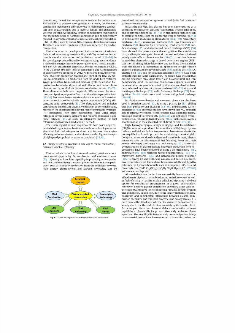
Plasma, which is the fourth state of matter, provides an un-precedented opportunity for combustion and emission control(Fig. 1.1) owing to its unique capability in producing active speciesand heat and modifying transport processes. New reaction path-ways, such as atomic O production from the collisions betweenhigh energy electrons/ions and oxygen molecules, can be
introduced into combustion systems to modify the fuel oxidationpathways considerably.
In last the two decades, plasma has been demonstrated as apromising technique to enhance combustion, reduce emissions,and improve fuel reforming [36 e 43] . In high speed propulsion suchas scramjet engines, since the pioneering work of Kimura et al. [44]in 1980s, recent studies using plasma torch [41,45 e 50] , lamentarydischarge [42,51] , microwave discharge [52] , low frequency arcdischarge [53] , streamer high frequency (HF) discharge [54] , sur-face discharge [55] , and nanosecond pulsed discharge (NSD) [56]have showed that plasma can enhance ignition, ame stabiliza-tion, and fuel/air mixing via chemical, thermal, and plasma inducedaerodynamic effects. Recent studies [57 e 62] have also demon-strated that plasma discharge in pulsed detonation engines (PDE)can shorten the ignition delay time, and facilitate the transitionfrom de agration to detonation. In applications for gas turbineengines, pulsed and steady plasma jets [63] , gliding arc [64] , DCelectric eld [65] , and HF streamer discharge [66,67] have beentested to increase ame stabilization. The results have showed thatplasma discharge can extend lower lean blowout limit and lean
ammability limit. For internal combustion engines, successfuldemonstrations of plasma assisted ignition and combustion havebeen achieved by using microwave discharge [68 e 71] , single andmulti-spark discharges [72] , radio frequency discharge [73] , laserignition [74 e 78] , and corona and nanosecond pulsed discharge[79 e 81] .
In addition to combustion enhancement, plasma has also beenused in emission control [82] . By using a plasma jet [83] , glidingarcs [82] , pulsed corona discharge [84 e 86] , and dielectric barrierdischarge [87,88] , extensive studies have shown that NO x emissioncan be effectively reduced. Recent studies have extended plasmaemission control to remove SO x [82,89,90] and unburned hydro-carbons (e.g., toluene and naphthalene) [91,92] in uegasas wellassoot formation in the exhausted gas of diesel engines [93 e 96] .
High hydrogen syngas, acetylene (C 2H2), and formaldehyde(CH2O) can also be produced from methane (CH 4), large hydro-
carbons, and biofuels by low temperature plasma to accelerate thenon-equilibrium kinetic process for maximizing chemical yield.Compared to conventional catalysts and steam reformers, plasmareformers have the advantages of fuel exibility, lower cost, highenergy ef ciency, and being fast and compact [97] . Successfuldemonstrations of plasma assisted hydrogen production from hy-drocarbons have been conducted by using a thermal plasma [98] ,gliding arcs [99 e 102] , dielectric barrier discharge (DBD) [103,104] ,microwave discharge [105] , and nanosecond pulsed discharge[106] . Recently, by using DBD and nanosecond pulsed discharge,low temperature cool ames have been successfully stabilized toreform large hydrocarbon fuels such as n-heptane (nC 7H16) anddimethyl ether (DME, CH 3OCH3) t o C 2H4, CH2O, H2 and CO [107,108]without carbon deposit.
Although the above studies have successfully demonstrated theeffectiveness of plasma in combustion and emission control as wellas fuel reforming, it remains unclear what kind of plasma is the bestoption for combustion enhancement in a given environment.Moreover, detailed plasma-combustion chemistry is not well un-derstood. Quantitative kinetic modeling remains dif cult even inone-dimension. In addition, due to the large variation of plasmaproperties and complicated interactions between plasma, com-bustion chemistry, and transport processes and aerodynamics, it iseven more dif cult to know whether the observed enhancement issimply due to the thermal effect or favorably by the kinetic effect.For example, there has been a debate on whether a non-equilibrium plasma discharge can kinetically enhance amespeed and ammability limit or can only promote ignition. Many
controversial results have been reported. It is not clear what theFig. 1.1. Schematic of plasma assisted combustion and applications.
Y. Ju, W. Sun / Progress in Energy and Combustion Science 48 (2015) 21 e 83 23
7/21/2019 Plasma Assisted Combustion Dynamics and Chemistry
http://slidepdf.com/reader/full/plasma-assisted-combustion-dynamics-and-chemistry 4/63
important kinetic pathways, radicals, and excited intermediatespecies are in plasma assisted combustion. There are many unan-swered fundamental questions behind the plasma “ magic ” . Forexample, how is the kinetic pathway of plasmaassistedcombustiondependent on plasma properties, temperature, and fuels? What isthe role of plasma if a fuel has low temperature chemistry? Howdoes plasma chemistry affect combustion chemistry and propertiesand so on? As such, fundamental understanding of plasma prop-erties and plasma assisted combustion chemistry in well-de nedphysical and chemical conditions is necessary to answer thesequestions.
1.3. Non-equilibrium plasma and the impact of plasma oncombustion
Plasma is a collection of neutral and charged particles which areelectrically neutral on average and exhibit collective effects. Thereare two types of plasmas, one is the equilibrium plasma in whichthe electron temperature, rotational and vibrational temperaturesof particles are in equilibrium and the neutral gas temperature andelectron number density are very high. The above mentionedplasma torch and spark plugs belong to this category. The other isthe non-equilibrium plasma in which the electronic, vibrational,and rotational temperatures are very different and the neutral gastemperature and electron number density are relatively low.Plasmas such as microwave discharge, DBD, gliding arc, streamerdischarge, and glow discharge belong to this category. Compared toequilibrium plasma, non-equilibrium plasma has higher electrontemperature (1 e 100 eV) and is more kinetically active due to the
rapid production of active radicals and excited species via electronimpact dissociation, excitation, and subsequent energy relaxation
[109,110] . Many of these electron impact processes are stronglyelectron energy dependent. Therefore, the extent of combustionenhancement by non-equilibrium plasma strongly depends onplasma properties, i.e., the electron temperature and electronnumber density.
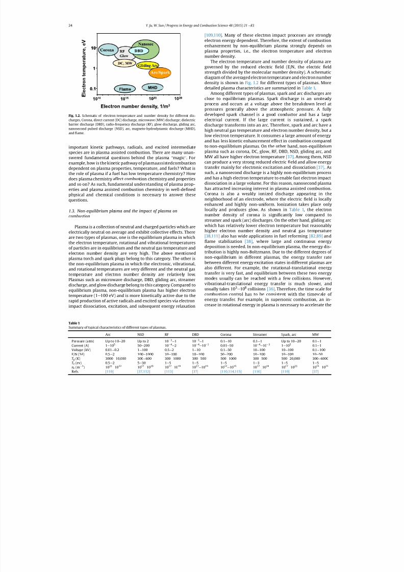
The electron temperature and number density of plasma aregoverned by the reduced electric eld (E/N, the electric eldstrength divided by the molecular number density). A schematicdiagram of the averaged electron temperature and electron numberdensity is shown in Fig. 1.2 for different types of plasmas. Moredetailed plasma characteristics are summarized in Table 1 .
Among different types of plasmas, spark and arc discharges areclose to equilibrium plasmas. Spark discharge is an unsteadyprocess and occurs at a voltage above the breakdown level atpressures generally above the atmospheric pressure. A fullydeveloped spark channel is a good conductor and has a largeelectrical current. If the large current is sustained, a sparkdischarge transforms into an arc. Therefore, spark and arc have ahigh neutral gas temperature and electron number density, but alow electron temperature. It consumes a large amount of energyand has less kinetic enhancement effect in combustion comparedto non-equilibrium plasmas. On the other hand, non-equilibriumplasma such as corona, DC, glow, RF, DBD, NSD, gliding arc, andMW all have higher electron temperature [37] . Among them, NSDcan produce a very strong reduced electric eld and allow energytransfer mainly for electronic excitation and dissociation [37] . Assuch, a nanosecond discharge is a highly non-equilibrium processand has a high electron temperature to enable fast electron impactdissociation in a large volume. For this reason, nanosecond plasmahas attracted increasing interest in plasma assisted combustion.Corona is also a weakly ionized discharge appearing in theneighborhood of an electrode, where the electric eld is locallyenhanced and highly non-uniform. Ionization takes place onlylocally and produces glow. As shown in Table 1 , the electronnumber density of corona is signi cantly low compared tostreamer and spark (arc) discharges. On the other hand, gliding arc
which has relatively lower electron temperature but reasonablyhigher electron number density and neutral gas temperature[38,111] also has wide applications in fuel reforming [82,89] and
ame stabilization [38] , where large and continuous energydeposition is needed. In non-equilibrium plasma, the energy dis-tribution is highly non-Boltzmann. Due to the different degrees of non-equilibrium in different plasmas, the energy transfer ratebetween different energy excitation states in different plasmas arealso different. For example, the rotational-translational energytransfer is very fast, and equilibrium between these two energymodes usually can be reached with a few collisions. However,vibrational-translational energy transfer is much slower, andusually takes 10 3
e 10 8 collisions [36] . Therefore, the time scale forcombustion control has to be consistent with the timescale of
energy transfer. For example, in supersonic combustion, an in-crease in rotational energy in plasma is necessary to accelerate the
Fig. 1.2. Schematic of electron temperature and number density for different dis-charges, Corona, direct current (DC) discharge, microwave (MW) discharge; dielectricbarrier discharge (DBD), radio-frequency discharge (RF), glow discharge, gliding arc,nanosecond pulsed discharge (NSD), arc, magneto-hydrodynamic discharge (MHD),and ame.
Table 1Summary of typical characteristics of different types of plasmas.
Arc NSD RF DBD Corona Streamer Spark, arc MW
Pressure (a tm) Up to 10 e 20 Up to 2 10 3e 1 10 3
e 1 0.1 e 10 0.1 e 1 Up to 10 e 20 0.1 e 1Current (A) 1 e 10 5 50 e 200 10 4
e 2 10 4e 10 3 0.01 e 50 10 4
e 10 3 1 e 10 5 0.1 e 1Voltage (kV) 0.01 e 0.2 1 e 100 0.5 e 2 1 e 10 0.1 e 50 10 e 100 10 e 100 0.1 e 100E/N (Td) 0.5 e 2 100 e 1000 10 e 100 10 e 100 50 e 200 10 e 100 10 e 100 10 e 50T g (K) 3000 e 10,000 300 e 600 300 e 1000 300 e 500 500 e 1000 300 e 500 500 e 20,000 300 e 6000T e (ev) 0.5 e 2 5 e 30 1 e 5 1 e 5 1 e 5 1 e 3 1 e 5 1 e 5ne (m 3) 10 21
e 10 22 10 17e 10 19 10 17
e 10 19 10 17e 10 19 10 12
e 10 15 10 17e 10 18 10 17
e 10 23 10 15e 10 23
Refs. [110] [37,112] [113] [37] [110,114,115] [110] [110] [37]
Y. Ju, W. Sun / Progress in Energy and Combustion Science 48 (2015) 21 e 8324
7/21/2019 Plasma Assisted Combustion Dynamics and Chemistry
http://slidepdf.com/reader/full/plasma-assisted-combustion-dynamics-and-chemistry 5/63
energy transfer to enhance ignition. Therefore, plasma assistedcombustion is also application dependent. To optimize plasmaassisted combustion, it is necessary to understand whichelementary process or what properties of plasma can generate thegreatest merits for combustion enhancement in each practicalapplication.
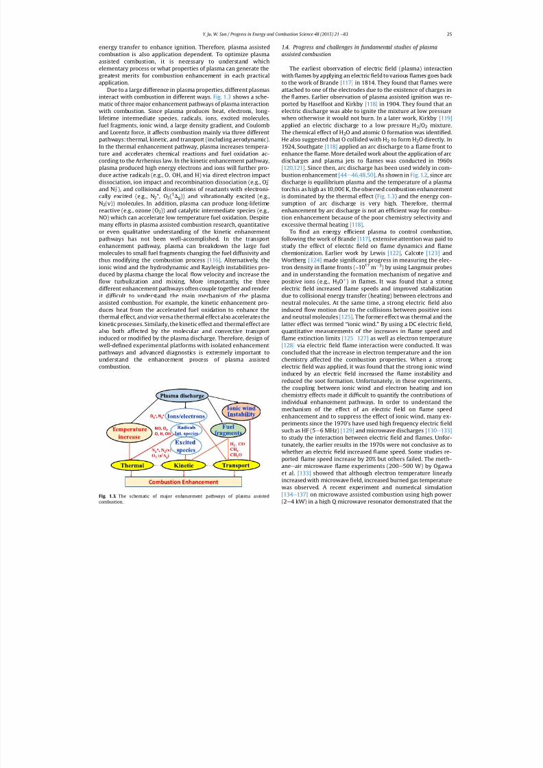
Due to a large difference in plasma properties, different plasmasinteract with combustion in different ways. Fig. 1.3 shows a sche-matic of three major enhancement pathways of plasma interactionwith combustion. Since plasma produces heat, electrons, long-lifetime intermediate species, radicals, ions, excited molecules,fuel fragments, ionic wind, a large density gradient, and Coulomband Lorentz force, it affects combustion mainly via three differentpathways: thermal, kinetic, and transport (including aerodynamic).In the thermal enhancement pathway, plasma increases tempera-ture and accelerates chemical reactions and fuel oxidation ac-cording to the Arrhenius law. In the kinetic enhancement pathway,plasma produced high energy electrons and ions will further pro-duce active radicals (e.g., O, OH, and H) via direct electron impactdissociation, ion impact and recombination dissociation (e.g., O 2
þ
and N 2þ ), and collisional dissociations of reactants with electroni-
cally excited (e.g., N 2*, O2(1Dg)) and vibrationally excited (e.g.,N2(v)) molecules. In addition, plasma can produce long-lifetimereactive (e.g., ozone (O 3)) and catalytic intermediate species (e.g.,NO) which can accelerate low temperature fuel oxidation. Despitemany efforts in plasma assisted combustion research, quantitativeor even qualitative understanding of the kinetic enhancementpathways has not been well-accomplished. In the transportenhancement pathway, plasma can breakdown the large fuelmolecules to small fuel fragments changing the fuel diffusivity andthus modifying the combustion process [116] . Alternatively, theionic wind and the hydrodynamic and Rayleigh instabilities pro-duced by plasma change the local ow velocity and increase the
ow turbulization and mixing. More importantly, the threedifferent enhancement pathways often couple together and renderit dif cult to understand the main mechanism of the plasma
assisted combustion. For example, the kinetic enhancement pro-duces heat from the accelerated fuel oxidation to enhance thethermal effect, and vice versa the thermal effect also accelerates thekinetic processes. Similarly, the kinetic effect and thermal effect arealso both affected by the molecular and convective transportinduced or modi ed by the plasma discharge. Therefore, design of well-de ned experimental platforms with isolated enhancementpathways and advanced diagnostics is extremely important tounderstand the enhancement process of plasma assistedcombustion.
1.4. Progress and challenges in fundamental studies of plasmaassisted combustion
The earliest observation of electric eld (plasma) interactionwith ames by applying an electric eld to various ames goes backto the work of Brande [117] in 1814. They found that ames wereattached to one of the electrodes due to the existence of charges inthe ames. Earlier observation of plasma assisted ignition was re-ported by Haselfoot and Kirkby [118] in 1904. They found that anelectric discharge was able to ignite the mixture at low pressurewhen otherwise it would not burn. In a later work, Kirkby [119]applied an electric discharge to a low pressure H 2/O2 mixture.The chemical effect of H 2O and atomic O formation was identi ed.He also suggested that O collided with H 2 to form H 2O directly. In1924, Southgate [118] applied an arc discharge to a ame front toenhance the ame. More detailed work about the application of arcdischarges and plasma jets to ames was conducted in 1960s[120,121] . Since then, arc discharge has been used widely in com-bustion enhancement [44 e 46,48,50] . As shown in Fig. 1.2 , since arcdischarge is equilibrium plasma and the temperature of a plasmatorchis as high as 10,000 K, the observed combustion enhancementis dominated by the thermal effect ( Fig. 1.3 ) and the energy con-sumption of arc discharge is very high. Therefore, thermalenhancement by arc discharge is not an ef cient way for combus-tion enhancement because of the poor chemistry selectivity andexcessive thermal heating [118] .
To nd an energy ef cient plasma to control combustion,following the work of Brande [117] , extensive attention was paid tostudy the effect of electric eld on ame dynamics and amechemionization. Earlier work by Lewis [122] , Calcote [123] andWortberg [124] made signi cant progress in measuring the elec-tron density in ame fronts (~10 17 m 3) by using Langmuir probesand in understanding the formation mechanism of negative andpositive ions (e.g., H 3Oþ ) in ames. It was found that a strongelectric eld increased ame speeds and improved stabilizationdue to collisional energy transfer (heating) between electrons and
neutral molecules. At the same time, a strong electric eld alsoinduced ow motion due to the collisions between positive ionsand neutral molecules [125] . The former effect was thermal and thelatter effect was termed “ ionic wind. ” By using a DC electric eld,quantitative measurements of the increases in ame speed and
ame extinction limits [125 e 127] as well as electron temperature[128] via electric eld ame interaction were conducted. It wasconcluded that the increase in electron temperature and the ionchemistry affected the combustion properties. When a strongelectric eld was applied, it was found that the strong ionic windinduced by an electric eld increased the ame instability andreduced the soot formation. Unfortunately, in these experiments,the coupling between ionic wind and electron heating and ionchemistry effects made it dif cult to quantify the contributions of
individual enhancement pathways. In order to understand themechanism of the effect of an electric eld on ame speedenhancement and to suppress the effect of ionic wind, many ex-periments since the 1970's have used high frequency electric eldsuch as HF (5 e 6 MHz) [129] and microwave discharges [130 e 133]to study the interaction between electric eld and ames. Unfor-tunately, the earlier results in the 1970s were not conclusive as towhether an electric eld increased ame speed. Some studies re-ported ame speed increase by 20% but others failed. The meth-ane e air microwave ame experiments (200 e 500 W) by Ogawaet al. [133] showed that although electron temperature linearlyincreased with microwave eld, increased burned gas temperaturewas observed. A recent experiment and numerical simulation[134 e 137] on microwave assisted combustion using high power
(2e
4 kW) in a high Q microwave resonator demonstrated that the
Fig. 1.3. The schematic of major enhancement pathways of plasma assisted
combustion.
Y. Ju, W. Sun / Progress in Energy and Combustion Science 48 (2015) 21 e 83 25
7/21/2019 Plasma Assisted Combustion Dynamics and Chemistry
http://slidepdf.com/reader/full/plasma-assisted-combustion-dynamics-and-chemistry 6/63
ame speed of lean methane e air mixture increased by approxi-mately 20%. Both the numerical modeling [134] and laser di-agnostics [137] showed that microwave absorption by the electronsin the ame zoneledto a ame temperature rise of about 200 K andthus accelerated ame propagation. Unfortunately, to avoidmicrowave- ame front interaction, the intensity of the electric eldused had to be lower than the breakdown voltage. Therefore, boththe energy and density of electrons in microwave discharge werelow and a large portion of the microwave energy was absorbed inthe burned gas, leading to a very inef cient energy coupling be-tween the ames and the electric eld.
Toincrease the electric eld and the electron numberdensity forthe effectiveness of plasma assisted ame stabilization, gliding arcswere tested in a counter ow diffusion ame to study extinction andignition of plasma assisted ame [38,138 e 140] by isolating thecomplexity of ow eld from plasma-combustion chemistry. Theresults from this idealized platform showed that a gliding arc with amoderate discharge power extended the ame extinction limit by afactor of three. However, by quantitatively measuring the temper-ature and OH distributions, it was found that almost all theenhancement was contributed by the thermal effect ( Fig. 1.3 ). Thisresult raised a question of whether and at what conditions plasmacan have a kinetic effect on combustion enhancement. The authorsthen extended their studies by comparing the ignition temperatureof hydrogen and methane with and without plasma [138,139] . Itwas found that gliding arc discharge in air reduced hydrogen andmethane ignition temperature kinetically by more than 100 K viathe catalytic NO x reaction pathways.
Subsequent quantitative measurements of radicals formation of nanosecond plasma discharge in counter ow diffusion amesdemonstrated that [43,106] , although far less than the effect onignition, plasma still extended slightly the extinction limit via ki-netic effect. These results prompted many questions on themechanism of plasma assisted combustion. First, why did glidingarc have only primarily thermal effect for ames but have a largekinetic effect on ignition? Does plasma really increase the ame
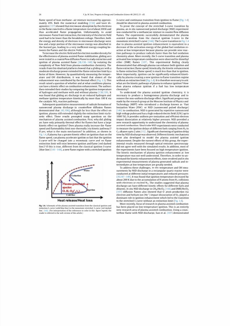
speed and ammability limit non-thermally (via kinetic pathway)?If yes, what is the main mechanism? In addition, as shown inFig.1.4 , if plasma has a greater kinetic effect on ignition than on the
ame speed, can plasma accelerate ignition so fast that the ignitionS -curve will be changed into a monotonic curve and no ameextinction limit will exist between ignition and ame (red dashedline)? If this is true, different from the classical ignition S -curve(blue line) [141 e 144] , a new ame regime with a stretched ignition
S -curve and continuous transition from ignition to ame ( Fig. 1.4 )should be observed in plasma assisted combustion.
To prove the concept of the stretched S -curve transition byplasma, an in situ nanosecond pulsed discharge (NSD) experimentwas conducted for a methane/air mixture in counter ow diffusion
ames. The experiments successfully demonstrated the plasmaassisted transition from the classical ignition S -curve to themonotonic stretched S -curve [144] . The S -curve transition in Fig.1.4due to plasma assisted ignition enhancement is equivalent to adecrease of the activation energy of the global fuel oxidation re-action at low temperature because plasma can provide new reac-tion pathways to produce radicals faster than the fuel oxidationchemistry alone. More recently, the S -curve transition and plasmaactivated low temperature combustion were observed for dimethylether (DME) ames [107] . This experimental nding clearlydemonstrated that although plasma can enhance both ignition and
ame extinction ( ame speed) kinetically, the kinetic enhancementto ame extinction ( ame speed) is much less than that to ignition.More importantly, ignition can be signi cantly enhanced kineti-cally by plasma creating a new ignition to ame transition regimewithout an extinction limit ( Fig.1.4 ). It is therefore necessary to ask:what are the kinetic pathways of plasma to enhance ignition? Howdoes plasma enhance ignition if a fuel has low temperaturechemistry?
To understand the plasma assisted ignition chemistry, it isnecessary to produce a homogeneous plasma discharge and toremove the non-uniform discharge effect. Signi cant progress wasmade by the research group at the Moscow Institute of Physics andTechnology (MIPT) who introduced a discharge known as “ FastIonization Wave (FIW) ” or NSD (nanosecond pulsed discharge)[146] to combustion. NSD is generated by repetitive nanosecondhigh voltage pulsesand has a high reduced electric eld (E/N) (up to1000 Td). It provides uniform pre-ionization and ef cient electronimpact dissociation at relatively higher pressure. NSD provided anew research opportunity to understand the chemistry of plasmaassisted combustion. Shock tube NSD experiments were conducted
to measure the ignition delays of different fuels ranging from H 2 toC5 alkanes upto 2 atm [112] . Signi cant shortening of ignition delaytime by NSD discharge was observed. Different kinetic mechanismswere also developed to model the plasma assisted ignitionenhancement. Despite the earnest efforts of this group, the exper-imental results measured through optical emission spectroscopydid not agree well with the simulated results. In addition, most of the experiments have been focused on high temperature ignition.The kinetic mechanism of plasma ignition enhancement at lowtemperature was not well understood. Therefore, in order to un-derstand the kinetic enhancement effects, time-resolved and in situexperimental measurements of plasma generated radicals and in-termediates at low temperature are greatly needed.
To address these challenges, in situ temperature and OH mea-
surements by NSD discharge in a rectangular quartz reactor wereconducted at different initial temperatures and reduced pressures[39,147 e 149] . It was found that ignition temperature decreased byabout 200 K due to the accumulation of H atoms from H 2 collisionswith electrons or excited N 2. The studies suggested that plasmadischarge can have different kinetic effects for different fuels anddiluents. In situ NSD discharge in CH 4/He/O 2 [144] and DME/He/O 2[107] diffusion ames also showed that O atom production viaelectron and helium ion (He þ ) impact dissociation of O 2 played adominant role in ignition enhancement which led to the transitionto the stretched S -curve without an extinction limit ( Fig. 1.4 ).
More recently, focus of research in plasma assisted combustionhas been placed on low temperature ignition. This is an entirelynew research area of plasma assisted combustion. Using a coun-
ter ow
ame with NSD discharge, Sun et al. [107] demonstrated
Fig. 1.4. Schematic of the plasma assisted transition from the classical ignition andextinction S -curve (solid blue line) to the monotonic stretched S -curve (red dashedline) [145] . (For interpretation of the references to color in this gure legend, the
reader is referred to the web version of this article.)
Y. Ju, W. Sun / Progress in Energy and Combustion Science 48 (2015) 21 e 8326
7/21/2019 Plasma Assisted Combustion Dynamics and Chemistry
http://slidepdf.com/reader/full/plasma-assisted-combustion-dynamics-and-chemistry 7/63
that plasma can activate low temperature multi-stage ignition evenat reduced pressure. Starikovskiy et al. [150] conducted NSDdischarge in a Rapid Compression Machine (RCM) to study theignition kinetics at elevated pressures up to 40 bar and low tem-perature regions (600 K-800 K). Two-orders of magnitude of igni-tion delay reduction was reported due to the streamerdevelopment. Similar work of ignition enhancement by nano-second pulsed surface dielectric barrier discharge in RCM wasconducted by Stepanyan et al. [151] Signi cant decrease of ignitiondelays for methane and n-butane mixtures in the pressure range of 7.5 e 15 atm was observed. A transient streamer plasma discharge inmethane and ethylene (C 2H4) [152] ignition was also conducted.Ignition enhancement was reported. Unfortunately, in the aboveexperiments, due to spatial non-uniformity of discharge, the kineticpathways of ignition enhancement were not well understood. Assuch, quantitative studies of the kinetic effect on combustionenhancement by plasma generated radicals and intermediate spe-cies on combustion in well-de ned experimental platforms areneeded.
As shown in Fig. 1.3, plasma generated intermediate species,radicals, and excited molecules can kinetically enhance combus-tion. Singlet delta oxygen (O 2(a
1Dg)) is a long-lifetime electronicallyexcited molecule. Its reaction with H atom (H þ O2(a 1Dg) ¼ OH þ O)is much faster than the most important H þ O2 ] OH þ O chainbranching reaction. Unfortunately, despite many numerical simu-lations of combustion enhancement by O 2(a
1Dg) [153,154] , fewexperimental studies on O 2(a
1Dg) combustion enhancement havebeen carried out. Smirnov et al. [155] performed experimentsaimed at isolating the effect of O 2(a
1Dg) on the ignition of H 2/O2mixtures at very low pressures (1 e 3 kPa). The results showeddecreased induction time, but O 2(a
1Dg) concentration was onlyqualitatively estimatedfrom the plasma emission. Due to the lack of quantitative diagnostics and the co-existence of ozone (O 3), atomicO and other radicals, it was not certain whether O 2(a 1Dg) was theonly species causing the enhancement. The isolated effect of O2(a
1Dg) on the propagation of C 2H4 lifted ames was studied
quantitatively for the rst time by Ombrello et al. [156] by isolatingthe effectof O 3 and atomic O via NO quenching. The results showedthat O 2(a
1Dg) only slightly increased the ame speed. Using thesame method, the kinetic enhancement effect of O 3 on ame speedwas reported [157] . The O3 enhancement of ame speed was alsoobserved in a ux burner [158,159] . More recently, it has beendiscovered that O 3 can enable stabilization of a self-sustained cool
ame for n-heptane (C 7H16) [108] . These experimental results,contrary to the previous results, have clearly indicated that O 3 cankinetically activate cool ame chemistry by releasing atomic O at alow temperature. However, large discrepancies between the modelprediction and experiments have been found.
Since atomic O formation in plasma has a signi cant impact oncombustion, another major achievement in the fundamental study
of plasma assisted combustion has been the success of quantitativediagnostics of atomic O. Uddi et al. measured the absolute atomic Oconcentration in NSD discharges using the Two Photon LaserInduced Fluorescence (TALIF) technique [160] . They found that Owas formed primarily from N 2( A) collision with O 2 and that atomicO decayed much faster in fuel/air mixtures than that in pure air.This indicated that atomic O production and its consumption byhydrocarbon fuels and radicals are one of the primary pathways forplasma assisted combustion. To further understand the formationpathways of atomic O production by excited N 2* (e.g., N2( A), N2(B)and N 2(C )) at a higher pressure, the absolute number densities of N2( A, B, C ) were measured by Cavity Ring Down Spectroscopy(CRDS) and Optical Emission Spectroscopy in a NSD discharge atatmospheric pressure in air [161] . Slightly different from the low
pressure results of [160] , the results showed that O 2 collisions with
N2(B) and N 2(C ) were the major reaction pathways to productatomic O (probably due to the difference in pressure). Thesequantitative measurements signi cantly advanced the under-standing of plasma assisted combustion. Measurements of atomic Oproduction and consumption of NSD in a helium (He) dilutedoxidizer stream of counter ow diffusion ames was also measuredby Sun et al. [106] using TALIF. It was also found that NSD dischargeproduced signi cant amount of atomic O via electron and heliumion impact dissociation of oxygen. These ndings support theobservation of improved ame stabilization of NSD discharge in aturbulent ow [40,67,162,163] .
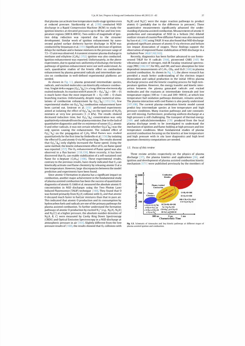
Recently, diagnostics has been further advanced to use femto-second TALIF for H radicals [164] , picosecond CARS [165] forvibrational states of nitrogen, mid-IR Faraday rotational spectros-copy (FRS) [166,167] for HO 2 and OH, and laser absorption for timedependent measurements of C 2H2, CH4, and H 2O [168] in plasmaassisted combustion. As shown in Fig. 1.5 , the above research hasprovided a much better understanding of the electron impactdissociation and radical production in the initial 100 ns plasmadischarge process and the kinetic coupling process for high tem-perature ignition. However, the energy transfer and kinetic inter-action between the plasma generated radicals and excitedmolecules and the reactants at intermediate timescale and lowtemperature region (100 ns e 1 ms and 300 e 900 K), at which lowtemperature fuel oxidation pathways dominate, remains unclear.The plasma interaction with cool ames is also poorly understood[107,108] . The current plasma-combustion kinetic model cannotpredict key intermediate species at low temperature and highpressure conditions. Many reaction pathways and rate constantsare still missing. Furthermore, producing uniform discharge at ahigh pressure is still challenging. The transport of thermal energy[169] and radicals/intermediates [170] produced from the localplasma discharge needs to be investigated to understand themechanism of ignition and ame-holding at high pressure and lowtemperature conditions. More fundamental studies of plasmaassisted combustion focusing on the kinetics at low temperature
and high pressure with in situ laser diagnostics and high levelquantum chemistry computations are needed.
1.5. Focus of this review
Three review articles respectively on the physics of plasmadischarge [37] , the plasma kinetics and applications [36] , andignition and development of plasma assisted combustion kineticmechanism [171] were published previously by the members of
Fig. 1.5. Schematic of timescales and key kinetic pathways at different stages of
plasma assisted ignition and combustion.
Y. Ju, W. Sun / Progress in Energy and Combustion Science 48 (2015) 21 e 83 27
7/21/2019 Plasma Assisted Combustion Dynamics and Chemistry
http://slidepdf.com/reader/full/plasma-assisted-combustion-dynamics-and-chemistry 8/63
former MIPT group. The rst review emphasized on experimentaland theoretical analyses of various non-equilibrium plasmas andtheir applications on ignition and combustion. The second reviewpaper expanded the rst review by including applications in lowand high speed propulsion as well as discharge kinetics. The thirdreviewcovered the results obtained from 2006 to 2014 with a focuson ignition study and developing a particular kinetic mechanismfor plasma assisted combustion. Although all reviews providedexcellent overviews of plasma assisted combustion from the viewpoint of plasma physics and kinetics, the underlying physics of combustion dynamics and chemistry as well as advanced di-agnostics were not emphasized. For example, questions such ashow and whether plasma can extend lean burn limit and changeminimum ignition energy were not answered. Moreover, thequestion of how different the kinetic pathways and combustionchemistry are for low and high temperature fuel oxidation inplasma assisted combustion was not addressed. Furthermore, sig-ni cant progress in advanced laser diagnostics and combustionkinetic mechanism development has been made. As such, this re-view intends to discuss and summarize the progress and challengesof plasma assisted combustion using the most recent experimentalresults from combustion theory, ame dynamics, chemistry, andadvanced diagnostics. The goals of this review are to: 1) discussdifferent enhancement pathways of plasma assisted combustionand bridge the gap between combustion dynamics and chemistryin plasma assisted combustion, especially for ignition, ame initi-ation, propagation and ammability limit; 2) present the importantkinetic pathways in low, intermediate, and high temperaturecombustion and use them to explain the physics and chemistry forplasma combustion enhancement in practical applications andlaboratory experiments; 3) provide a broad overview of funda-mental phenomena and kinetic processes in plasma assisted com-bustion experiments with well-de ned boundary and dischargeconditions; 4) present the recent progress and ndings made byadvanced laser diagnostic techniques and combustion theory; and5) discuss the recent ndings of plasma assisted low temperature
combustion and cool ames; and nally 6) discuss the challengesand needs of future research in plasma assisted combustion.
2. Plasma assisted combustion: applications andtechnological development
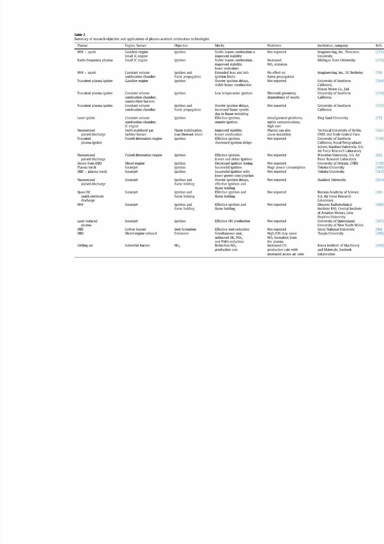
In the last two decades, many different plasmas includingplasma torch, dielectric barrier discharge (DBD), gliding arc, corona,nanosecond pulsed plasma discharge, microwave, and lasers havebeen widely tested and applied in high speed propulsion systems,internal combustion engines, industrial burners, and reactors tocontrol ignition, ame holding, ame stability, lean burn, emis-sions, and fuel reforming. Table 2 below lists the types of plasmaand combustors, merits of combustion enhancement, technical
dif culties and challenges, references, and the names of in-stitutions. In the sections below, the details of major research ef-forts, results and progress, challenges, and future directions will bereviewed and discussed for high speed propulsion, internal com-bustion engines, emission control, and fuel reforming.
2.1. Plasma assisted combustion for supersonic propulsion andscramjet engines
The major challenges in supersonic ramjet engines for hyper-sonic propulsion are fuel/air mixing, ignition, ame stabilization,and cooling [13,190] . At a high Mach number, the ow residencetime in the engine ( t ow ~ 0.5 ms) is even shorter than the typicalauto-ignition time of jet fuels ( t ig ~1 e 2 ms) at 900 K [191] . More-
over, even when the fuel is ignited, the ow residence time maystill
be shorter than the time for the fuel to be completely combusted(t c). Therefore, both the ignition and combustion Damk
€
ohlernumbers are less than unity.
Da ig ¼t flow
t ig < 1 and Dac ¼
t flow
t c < 1 (2.1)
In addition, if the combustion heat release is too fast, the rapidheat release rate may cause thermal choking of the ow and lead toan engine unstart. Therefore, it is necessary to control both ignitionand combustion heat release rate. Plasma torch or plasma jet hasbeen extensively studied as an effective method to ignite and sta-bilize ame at supersonic conditions [36,41,44 e 51] . Plasma torch isan equilibrium arc discharge and is considered to enhance ignitiondue to the thermal effect and abundant active radicals. Theextremely high temperature (up to 10,000 K) of the plasma torchmakes the thermal effect overwhelm the kinetic effect.
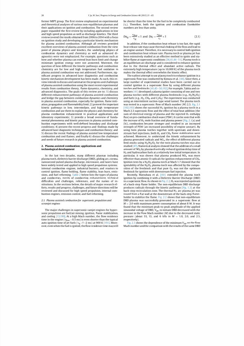
The earliest attempt to use plasma torch to enhance ignition in asupersonic ow was conducted by Kimura et al. [44] . Since then, alarge number of experimental studies have been carried out tocontrol ignition in a supersonic ow by using different plasmatorches and feedstocks [41,45 e 50,192] . For example, Takita and co-workers [41] developed a plasma igniter consisting of one and twoplasma torches with different plasma feedstocks (e.g., H 2/N2/O2)and fuels (e.g., H 2, CH4, and C 2H4). The experiment was conductedusing an intermittent suction-type wind tunnel. The plasma torchwas tested in a supersonic ow of Mach number ( M ) 2.3. Fig. 2.1[192,193] shows the successful H 2 ignition by a plasma torch in aMach 2.3 supersonic ow and the effect of total heat addition (thesum of electrical energy of plasma and the injected H 2 enthalpy
ux) on pre-combustion shock wave (PSW). It can be seen that withthe increase of H 2 mole fraction and plasma power ( Fig. 2.1 (a) and(b)), combustion became stronger and resulted in an increasedstrength of PSW (an increased possibility of engine unstart). Byusing twin plasma torches together with upstream and down-stream fuel injections, both H 2 and CH 4 ame stabilization were
achieved. Moreover, to understand the kinetic enhancement byplasma generated radicals and NO x, the effect of different plasmafeed-stocks using H 2/N 2/O2 for the twin plasma torches was alsostudied [47] . Numerical analysis showed that the addition of a smallamount of NO x by plasma drastically reduced ignition delay time of H2 and hydrocarbon fuels at a relatively low initial temperature. Inparticular, it was shown that plasma produced NO x was moreeffective than atomic O radicals for ignition enhancement of CH 4.Ignition tests by a N 2/O2 plasma torch at Mach 1.7 showed that theignitability of the N 2/O2 plasma torch was affected by the compo-sition of the feedstock and that pure O 2 was not the optimumfeedstock for ignition with downstream fuel injection.
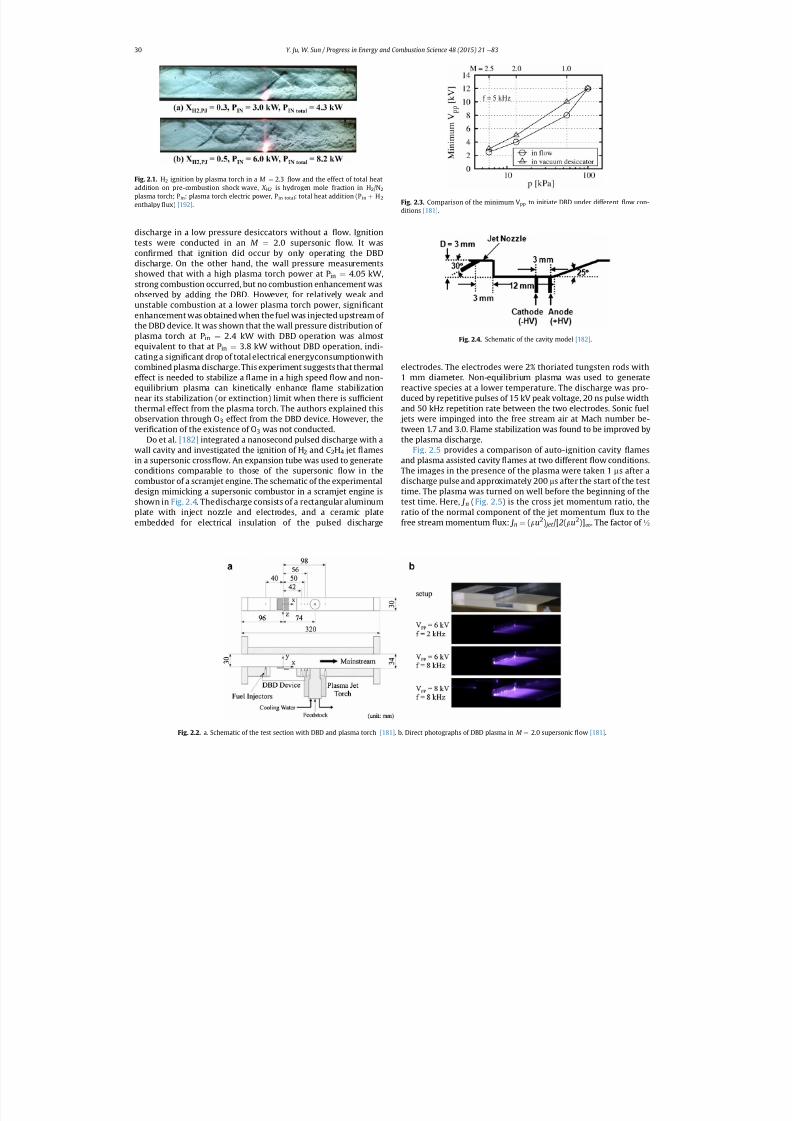
Recently, Matsubara et al. [181] extended the plasma torchignition by combining it with a Dielectric Barrier Discharge (DBD)
in a supersonic ow. As shown in Fig. 2.2 , H2 was injected upstreamof a back-step ame holder. The non-equilibrium DBD dischargeproduces radicals through the kinetic pathways ( Fig. 1.3 ) at theback-step recirculation zone. The thermal N 2 arc plasma jet wasissued from a at wall at the downstream of the back-step ame-holder to stabilize the ame. Fig. 2.2 shows that non-equilibriumDBD plasma was successfully generated in a supersonic ow atM ¼ 2.0 with maximum power consumption of about 8 W. It wasfound that the minimum peak-to-peak amplitude of the appliedsinusoidal voltage of DBD, V pp , to initiate DBD decreased with theincrease in the ow Mach number ( M ) due to the decreased staticpressure (about 55, 13, and 6 kPa in M ¼ 1.0, 2.0, and 2.5,respectively).
Fig. 2.3 shows the dependence of the minimum V pp on the ow
Mach number andthe comparison with the results of the same DBD
Y. Ju, W. Sun / Progress in Energy and Combustion Science 48 (2015) 21 e 8328
7/21/2019 Plasma Assisted Combustion Dynamics and Chemistry
http://slidepdf.com/reader/full/plasma-assisted-combustion-dynamics-and-chemistry 9/63
7/21/2019 Plasma Assisted Combustion Dynamics and Chemistry
http://slidepdf.com/reader/full/plasma-assisted-combustion-dynamics-and-chemistry 10/63
discharge in a low pressure desiccators without a ow. Ignitiontests were conducted in an M ¼ 2.0 supersonic ow. It wascon rmed that ignition did occur by only operating the DBDdischarge. On the other hand, the wall pressure measurementsshowed that with a high plasma torch power at P in ¼ 4.05 kW,strong combustion occurred, but no combustion enhancement was
observed by adding the DBD. However, for relatively weak andunstable combustion at a lower plasma torch power, signi cantenhancement was obtained when the fuel was injected upstream of the DBD device. It was shown that the wall pressure distribution of plasma torch at P in ¼ 2.4 kW with DBD operation was almostequivalent to that at P in ¼ 3.8 kW without DBD operation, indi-cating a signi cant drop of total electrical energyconsumptionwithcombined plasma discharge. This experiment suggests that thermaleffect is needed to stabilize a ame in a high speed ow and non-equilibrium plasma can kinetically enhance ame stabilizationnear its stabilization (or extinction) limit when there is suf cientthermal effect from the plasma torch. The authors explained thisobservation through O 3 effect from the DBD device. However, theveri cation of the existence of O 3 was not conducted.
Do et al. [182] integrated a nanosecond pulsed discharge with awall cavity and investigated the ignition of H 2 and C 2H4 jet amesin a supersonic cross ow. An expansion tube was used to generateconditions comparable to those of the supersonic ow in thecombustor of a scramjet engine. The schematic of the experimentaldesign mimicking a supersonic combustor in a scramjet engine isshown in Fig. 2.4. The discharge consists of a rectangular aluminumplate with inject nozzle and electrodes, and a ceramic plateembedded for electrical insulation of the pulsed discharge
electrodes. The electrodes were 2% thoriated tungsten rods with1 mm diameter. Non-equilibrium plasma was used to generatereactive species at a lower temperature. The discharge was pro-duced by repetitive pulses of 15 kV peak voltage, 20 ns pulse widthand 50 kHz repetition rate between the two electrodes. Sonic fuel jets were impinged into the free stream air at Mach number be-tween 1.7 and 3.0. Flame stabilization was found to be improved by
the plasma discharge.Fig. 2.5 provides a comparison of auto-ignition cavity amesand plasma assisted cavity ames at two different ow conditions.The images in the presence of the plasma were taken 1 ms after adischarge pulse and approximately 200 ms after the start of the testtime. The plasma was turned on well before the beginning of thetest time. Here, J n (Fig. 2.5 ) is the cross jet momentum ratio, theratio of the normal component of the jet momentum ux to thefree stream momentum ux: J n ¼ (r u2) jet /[ 2(r u2)] ∞ . The factor of ½
Fig. 2.2. a. Schematic of the test section with DBD and plasma torch [181] . b. Direct photographs of DBD plasma in M ¼
2.0 supersonic
ow [181] .
Fig. 2.1. H2 ignition by plasma torch in a M ¼ 2.3 ow and the effect of total heataddition on pre-combustion shock wave, X H2 is hydrogen mole fraction in H 2/N2
plasma torch; P in : plasma torch electric power, P in total : total heat addition (P in þ H2
enthalpy ux) [192] . Fig. 2.3. Comparison of the minimum V pp to initiate DBD under different ow con-ditions [181] .
Fig. 2.4. Schematic of the cavity model [182] .
Y. Ju, W. Sun / Progress in Energy and Combustion Science 48 (2015) 21 e 8330

7/21/2019 Plasma Assisted Combustion Dynamics and Chemistry
http://slidepdf.com/reader/full/plasma-assisted-combustion-dynamics-and-chemistry 11/63
comes from the 30 injection relative to the free stream ow di-rection. The plasma enhanced cavity ames seen in Fig. 2.5(b) and(d) clearly appeared to extend into the free stream ow on theleeward side of the fuel jet. The results showed that the pulsedplasma in the cavity served as a source of both heat and radicals,shortening the ignition delay time of the well mixed ammablemixture. In a marginal case with M ¼ 2.0 and stagnation enthalpy~2.0 MJ/kg, H 2 jet auto-ignition was observed within the test timewhich is about 500 ms only with plasma enhancement. A simplemodel was also employed to simulate the experiments. The au-thors concluded that the reduction of the ignition delays was dueto H and atomic O through electron impact dissociation of H 2
and O 2 .To reduce the pressure loss and eliminate the coupling between
cavity and plasma discharge, Do et al. [182] further conducted theame-holding experiments with plasma discharge in a supersonic
cross ow without a cavity. Subsonic (upstream) and sonic (down-stream) fuel (H 2 and C 2H4) jets were injected into a pure oxygenfree stream of M ¼ 1.7 e 2.4. The con guration of duel fuel jet in- jection with plasma in between can couple the plasma energy intothe activation of the upstream subsonic fuel/oxidizer mixture thatserved as a pilot ame that subsequently anchored the ignition of the main supersonic ame downstream. Radical production by thispilot ame can be several orders of magnitude more than that bythe discharge alone. The observed ame stabilization enhancementis shown schematically in Fig. 1.3, indicating that both thermal ef-
fect (cavity or pilot
ame) and kinetic effect are needed for
ameholding in a supersonic ow. However, in both experiments it wasnot discussed at what temperature range and ow residence timethis kinetic enhancement is most effective. It was not clear whetherthe observed enhancement is due to the ignition shortening or dueto the ame speed increase.
Leonov et al. [184] developed an experimental platform of plasma assisted supersonic combustion by integrating multi-electrode quasi DC discharge (similar to gliding arc) behind aback-step cavity in H 2 and C 2H4 with air mixtures ( Fig. 2.6 ). Thedischarge dynamics in ow behind the back-step and in the cavitywas explored. It was found that the discharge effect on the owstructure in the cavity and behind the back-step lied in that anintensive turbulization of gas in the interaction area and simulta-neously slight increase of the separation zone volume. The direct
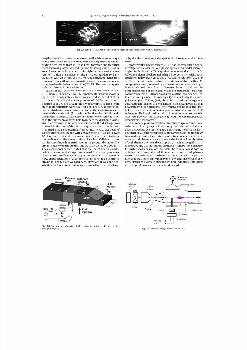
photographs of the multi-electrode discharge and associatedcombustion are shown in Fig. 2.7. With H 2 injection, the combus-tion took place in the cavity as well as in the shear layer. For C 2H4,combustion was only detected in the cavity. The authors proposedthree mechanisms for high-speed combustion control: plasma-induced ignition, plasma-intensi ed mixing, and ame-holdingby plasma generation.
Leonov et al. [183,185] further conducted experiments onplasma-induced H 2 and C 2H4 ignition and ame holding by meansof near-surface electrical discharges in M ¼ 2 ow. The modi edexperimental setup is shown in Fig. 2.8. The fuel injectors werelocated downstream of the plasma generator on a distance that was
less than the plasma lament length. The injectors were arrangedat the same position as the electrodes for the most intensive air-plasma interaction with the fuel jet. Fuel injection was startedprior to the discharge initiation and was switched off aftercompletion of the discharge. The discharge appeared in the form of oscillating plasma laments. The individual laments were blowndown due to the main ow at a velocity that was a bit less than thecore value. It was found that the ame could only exist in thepresence of the plasma. The authors proposed a two zone model of plasma induced ignition to explain the experimental data. In zone 1,the cold combustion took place accompanied by plasma inducedfuel conversion and relatively small heat release. In zone 2, com-bustion was completed or almost completed with high energyrelease. The plasma launched the cold combustion inside zone 1
owing to the generation of high amounts of active species. The
Fig. 2.5. OH PLIF images of a cavity ame in supersonic ows of two different enthalpies: (a) without the plasma and (b) with plasma at M ¼ 2.9, J n ~ 4 of H2 jet, and (c) withoutplasma and (d) with plasma at M ¼ 2.6 J n ~ 3.5 of H2 jet [182] .
Fig. 2.6. Schematic of experimental setup and electrodes arrangement [184] .
Y. Ju, W. Sun / Progress in Energy and Combustion Science 48 (2015) 21 e 83 31
7/21/2019 Plasma Assisted Combustion Dynamics and Chemistry
http://slidepdf.com/reader/full/plasma-assisted-combustion-dynamics-and-chemistry 12/63
lengths of zone 1 in the tests were measuredby Schlierentechniquein the range from 50 to 150 mm, which corresponded to the in-duction time range from 0.1 to 0.3 ms. However, the transitionmechanism of plasma assisted ignition to strong combustion inzone 2 was not well understood. It might be the classical auto-ignition to ame transition or the stretched ignition to ametransition without extinction limit. More quantitative diagnostics isnecessary. The authors are conducting species measurements byusing tunable diode-laser absorption (TDLAS). The results may givea clearer picture of the mechanism.
Esakov et al. [186] studied microwave assisted combustion of C3H8/air in a supersonic ow. The experimental setup is shown inFig. 2.9 . The steady state airstream was formed at the outlet of thenozzle with M ¼ 2 and a static pressure of 100 Torr, static tem-perature of 150 K, and stream velocity of 490 m/s. The free streamstagnation conditions were 550 Torr and 300 K. A deeply undercritical discharge was created by an incident electromagneticbeam with electric eld ( E ) much smaller than the critical break-down eld. In order to create a local electric eld which was largerthan the critical breakdown eld to initiate the discharge, a pas-sive electrodynamic vibrator was used and the discharge wasinitiated in the base of the electromagnetic vibrator, which wasimmersed in cold supersonic air ow. A linearly polarized beam of electro-magnetic radiation with a wavelength of 12.5 cm, power1.5 kW and a typical transverse size 9 cm was introducedperpendicular to the screen surface. A C 3H8 or C3H8/air mixturewas injected through internal tubes in the pylon and vibrator. Thestream velocity on the stream axis was approximately 200 m/s.The experiments demonstrated that the use of a deeply undercritical microwave discharge can be used to effectively increasethe combustion ef ciency of C 3H8/air mixture in cold supersonic
ow. Stable operation of a hot combustion torch in a supersonicstream in steady state was achieved. However, it was not clearwhether the ame stabilization was enhanced by the arc discharge
or by the electron energy absorption of microwave at the amefront.
More recently, Brieschenk et al. [187] has reported experimentalinvestigation on laser induced plasma ignition in a model scramjetengine for the rst time. The experiments were conducted in the T-ADFA free piston shock tunnel using a ow condition with a totalspeci c enthalpy of 2.7 MJ/kg and a free stream velocity of 2075 m/s. The scramjet model features a rectangular duct with a 9compression ramp, followed by a constant-area combustor. H 2 isinjected through four 2 mm diameter holes located on the
compression ramp of the model, which are distributed across thecompression ramp, 120 mm downstream of the leading edge. Thelaser induced plasma is formed by a Q-switched ruby laser withpulse energies of 750 mJ (only about 54% of the laser energy wasabsorbed). The location of the plasma is in the shear layers 1.7 mmdownstream of the injectors. The temporal evolution of the laserinduced plasma ignition region was monitored using OH PLIFtechnique. Hydroxyl radical (OH) formation was successfullyobserved. However, the subsequent ignition and ame propagationevents were not reported.
In summary, plasma activation can enhance ignition and amestabilization in a high speed ow through both thermal and kineticeffects. However, due to strong turbulent mixing (heat/radical loss)and short ow residence time (requiring a very short ignition delaytime and fast heat release rate), combustion enhancement usingnon-thermal plasma alone is extremely challenging. A combinationof both thermal and non-thermal plasmas such as the gliding arc/microwave and plasma jet/DBD discharge might be more effectivefor high speed applications. As such, the kinetic mechanism tooptimize the combination of thermal and non-thermal plasmasneeds to be understood. Furthermore, the introduction of plasmadischarge may signi cantly modify the ow eld. The effect of owperturbation by plasma in affecting ignition and ame stabilizationin high speed ow also needs to be addressed.
Fig. 2.8. Experimental schematic of the combustor bottom wall and the test
arrangement [185] . Fig. 2.9. Schematic of experimental setup [186] .
Fig. 2.7. Left: discharge without fuel injection. Right: discharge interaction with H 2 injection [184] .
Y. Ju, W. Sun / Progress in Energy and Combustion Science 48 (2015) 21 e 8332
7/21/2019 Plasma Assisted Combustion Dynamics and Chemistry
http://slidepdf.com/reader/full/plasma-assisted-combustion-dynamics-and-chemistry 13/63
2.2. Ignition enhancement by plasma in internal combustionengines
Over the last decade, plasma assisted combustion has attractedincreasing attention for applications in internal combustion en-gines such as gasoline and diesel engines [68 e 81] , gas turbineengines [63,64] , pulsed detonation engines [36,37,58 e 62] , and leanburn combustion systems [37,45,51 e 56,66,67,194,195] . In sparkignition (SI) engines, the development of the initial spark ignitionkernel size strongly in uences the lean burn limit and emissioncharacteristics. A larger ignition kernel size can extend the leanburn limit forlarge hydrocarbon fuels [196] . In order to improve theignition of SI engines, different plasmas such as microwave [68,69] ,
NSD [81] , and gliding arc [197] have been used to replace or inte-grate with a conventional spark plug. A schematic of the integrationof different plasmas with a conventional spark plug and a com-parison of spark sizes are shown in Figs. 2.10 and 2.11 , respectively.Fig. 2.11 shows that using a gliding arc and microwave discharge atthe same pressure of 1 MPa the ignition kernel sizes are muchgreater than that of the conventional spark plug.
Ikeda and collaborators developed and tested a microwave in-tegrated spark igniter [68,69] that can be applied to existing enginesystems without any engine modi cation. As shown in Fig. 2.10 ,microwave discharge at a frequency of 2.45 GHz was generated by acommercial magnetron into a non-resistor spark plug which hasthe same geometry as that of a conventional spark plug. The twoelectrodes of the spark plug also acted as a microwave antenna. Themicrowave system operated in burst mode, in which a series of pulses of 2.45 GHz microwave energy were delivered to the sparkplug starting before and ending after the standard spark. The mi-crowave energy was then absorbed by the electrons formed by thespark between the two electrodes that raised the electrons to ahigher temperature. These electrons collided with the gas mole-cules and raised the gas temperature and created excited speciesand active radicals. In an earlier work [198] , the rotational tem-perature and N 2 density were measured by rotational Ramanscattering in the region of the microwave discharge. It was shownthat at a microwave power less than the ignition energy of a sparkplug, the rotational temperature raised to a maximum of 1500 K ina nitrogen/helium mixture by microwave.
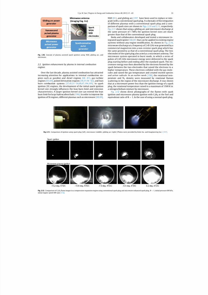
Fig. 2.12 shows direct photographs of the ames with sparkignition and microwave plasma ignition with C 3H8 at the fuel andequivalence ratio of F ¼ 1. In the case of using a normal spark plug,
Fig. 2.12. Comparison of C 3H8 ame images in a compression-expansion engine using conventional spark plug and microwave enhanced spark plug, F ¼ 1, initial pressure 600 kPa,
initial engine speed 600 rpm [172] .
Fig. 2.11. Comparison of ignition using spark plug (left), microwave (middle), gliding arc (right) (Photos were provided by Knite Inc. and Imagineering Inc.) [197] .
Fig. 2.10. Concept of plasma assisted spark ignition using NSD, gliding arc, andmicrowave.
Y. Ju, W. Sun / Progress in Energy and Combustion Science 48 (2015) 21 e 83 33
7/21/2019 Plasma Assisted Combustion Dynamics and Chemistry
http://slidepdf.com/reader/full/plasma-assisted-combustion-dynamics-and-chemistry 14/63
spark discharge was observed at 14.2 after top dead center(ATDC). The ame kernel was formed at 7.0 ATDC, and then the
ame propagated at 0.2 ATDC. With the microwave enhancedspark plug, intense light from the plasmawas observed shortly afterspark ignition. Then, a large ame kernel was formed by the mi-crowave energy addition at 0.2 ATDC.
The microwave enhanced spark plug was further tested using a499.6 cc, four-stroke- single cylinder gasoline research engine at aconstant indicated mean effective pressure (IMEP) of 275 kPa and2000 rpm. Theeffects of the microwave enhanced spark plug on thelean limit, fuel consumption, and exhaust emissions were evalu-ated. The results are shown in Fig. 2.13 . With a spark plug igniter, atair/fuel mass ratio (A/F) of 17, the cyclic variation coef cient of IMEP(COV IMEP) increased dramatically, indicating close to the lean limitof the engine. In contrast, with the microwave enhanced spark plug,the COV remained essentially constant until A/F ¼ 22. Moreover,MW also reduced the fuel consumption (FC) and CO emissions for
A/F greater than 18.Wolk et al. [70] further investigated the performance of the
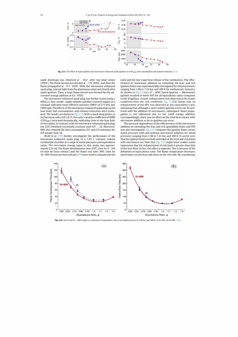
microwave enhanced spark plug in a 1.45 L constant volumecombustion chamber at a range of initial pressures and equivalenceratios. The microwave energy input in this study was approxi-mately 225 mJ. The ame development time (FDT, time for 0 e 10%of total net heat release) and the ame rise time (FRT, time for10 e 90% of total net heat release) [70] were used to characterize the
early and the late stage heat release of the combustion. The effec-tiveness of microwave addition on extending the lean and richignition limits was experimentally investigated for initial pressuresranging from 1.08 to 7.22 bar and 300 K for methane/air mixtures.As shown in Fig. 2.14 (a), SI þ MW (Spark Ignition þ Microwave)ignition resulted in lower FDT for all equivalence ratios comparedto the SI ignition. Greater enhancement was observed at the leanerconditions than the rich conditions. Fig. 2.14 (b) shows that noenhancement of the FRT was observed at any equivalence ratio,indicating that although a more robust ignition event can be ach-ieved with the addition of microwaves, subsequent ame propa-gation is not in uenced due to the small energy addition.Correspondingly, there was no effect on the total heat release withmicrowave addition as far as ignition can occur.
The pressure dependence of the effectiveness of the microwaveaddition on extending the lean and rich ignitability limits and FDTwas also investigated. Fig. 2.15 compares the ignition limits versus
initial pressure with and without microwave addition for initialpressures ranging from 1.08 to 7.22 bar and 300 K. It can be seenthat the ignition limits are both extended at the lean and rich limitswith microwave use. Note that Fig. 2.15 might leave readers someimpression that the enhancement of rich limit is greater than thatof the lean limit. In fact, the effect is opposite. This is because of thede nition of equivalence ratio. The ame temperature decreasesmuch faster on the lean side than on the rich side. By considering
Fig. 2.13. The effect of spark ignition and microwave enhanced spark ignition on COV IMEP, fuel consumption and exhaust emission [172] .
Fig. 2.14. the SI and SI þ
MW modes as a function of equivalence ratio at an initial pressure of 1.08 bar and 300 K (a) for FDT, (b) for FRT [70] .
Y. Ju, W. Sun / Progress in Energy and Combustion Science 48 (2015) 21 e 8334
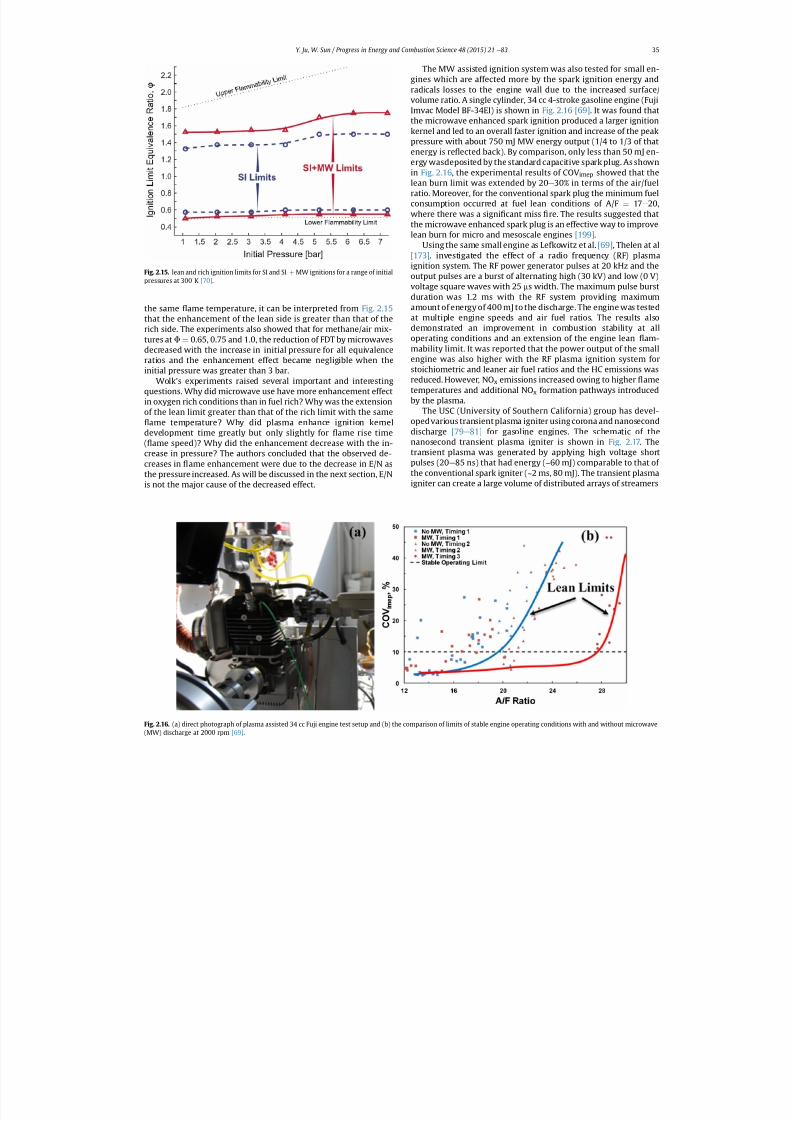
7/21/2019 Plasma Assisted Combustion Dynamics and Chemistry
http://slidepdf.com/reader/full/plasma-assisted-combustion-dynamics-and-chemistry 15/63
the same ame temperature, it can be interpreted from Fig. 2.15that the enhancement of the lean side is greater than that of therich side. The experiments also showed that for methane/air mix-tures at F ¼ 0.65, 0.75 and 1.0, the reduction of FDT by microwavesdecreased with the increase in initial pressure for all equivalenceratios and the enhancement effect became negligible when theinitial pressure was greater than 3 bar.
Wolk's experiments raised several important and interestingquestions. Why did microwave use have more enhancement effectin oxygen rich conditions than in fuel rich? Why was the extensionof the lean limit greater than that of the rich limit with the same
ame temperature? Why did plasma enhance ignition kerneldevelopment time greatly but only slightly for ame rise time( ame speed)? Why did the enhancement decrease with the in-crease in pressure? The authors concluded that the observed de-creases in ame enhancement were due to the decrease in E/N asthe pressure increased. As will be discussed in the next section, E/Nis not the major cause of the decreased effect.
The MW assisted ignition system was also tested for small en-gines which are affected more by the spark ignition energy andradicals losses to the engine wall due to the increased surface/volume ratio. A single cylinder, 34 cc 4-stroke gasoline engine (FujiImvac Model BF-34EI) is shown in Fig. 2.16 [69] . It was found thatthe microwave enhanced spark ignition produced a larger ignitionkernel and led to an overall faster ignition and increase of the peakpressure with about 750 mJ MW energy output (1/4 to 1/3 of thatenergy is re ected back). By comparison, only less than 50 mJ en-ergy wasdeposited by the standard capacitive spark plug. As shownin Fig. 2.16 , the experimental results of COV imep showed that thelean burn limit was extended by 20 e 30% in terms of the air/fuelratio. Moreover, for the conventional spark plug the minimum fuelconsumption occurred at fuel lean conditions of A/F ¼ 17 e 20,where there was a signi cant miss re. The results suggested thatthe microwave enhanced spark plug is an effective way to improvelean burn for micro and mesoscale engines [199] .
Using the same small engine as Lefkowitz et al. [69] , Thelen at al[173] . investigated the effect of a radio frequency (RF) plasmaignition system. The RF power generator pulses at 20 kHz and theoutput pulses are a burst of alternating high (30 kV) and low (0 V)voltage square waves with 25 ms width. The maximum pulse burstduration was 1.2 ms with the RF system providing maximumamount of energy of 400 mJ to the discharge. The engine was testedat multiple engine speeds and air fuel ratios. The results alsodemonstrated an improvement in combustion stability at alloperating conditions and an extension of the engine lean am-mability limit. It was reported that the power output of the smallengine was also higher with the RF plasma ignition system forstoichiometric and leaner air fuel ratios and the HC emissions wasreduced. However, NO x emissions increased owing to higher ametemperatures and additional NO x formation pathways introducedby the plasma.
The USC (University of Southern California) group has devel-opedvarious transient plasma igniter using corona and nanoseconddischarge [79 e 81] for gasoline engines. The schematic of the
nanosecond transient plasma igniter is shown in Fig. 2.17. Thetransient plasma was generated by applying high voltage shortpulses (20 e 85 ns) that had energy (~60 mJ) comparable to that of the conventional spark igniter (~2 ms, 80 mJ). The transient plasmaigniter can create a large volume of distributed arrays of streamers
Fig. 2.16. (a) direct photograph of plasma assisted 34 cc Fuji engine test setup and (b) the comparison of limits of stable engine operating conditions with and without microwave
(MW) discharge at 2000 rpm [69] .
Fig. 2.15. lean and rich ignition limits for SI and SI þ MW ignitions for a range of initialpressures at 300 K [70] .
Y. Ju, W. Sun / Progress in Energy and Combustion Science 48 (2015) 21 e 83 35
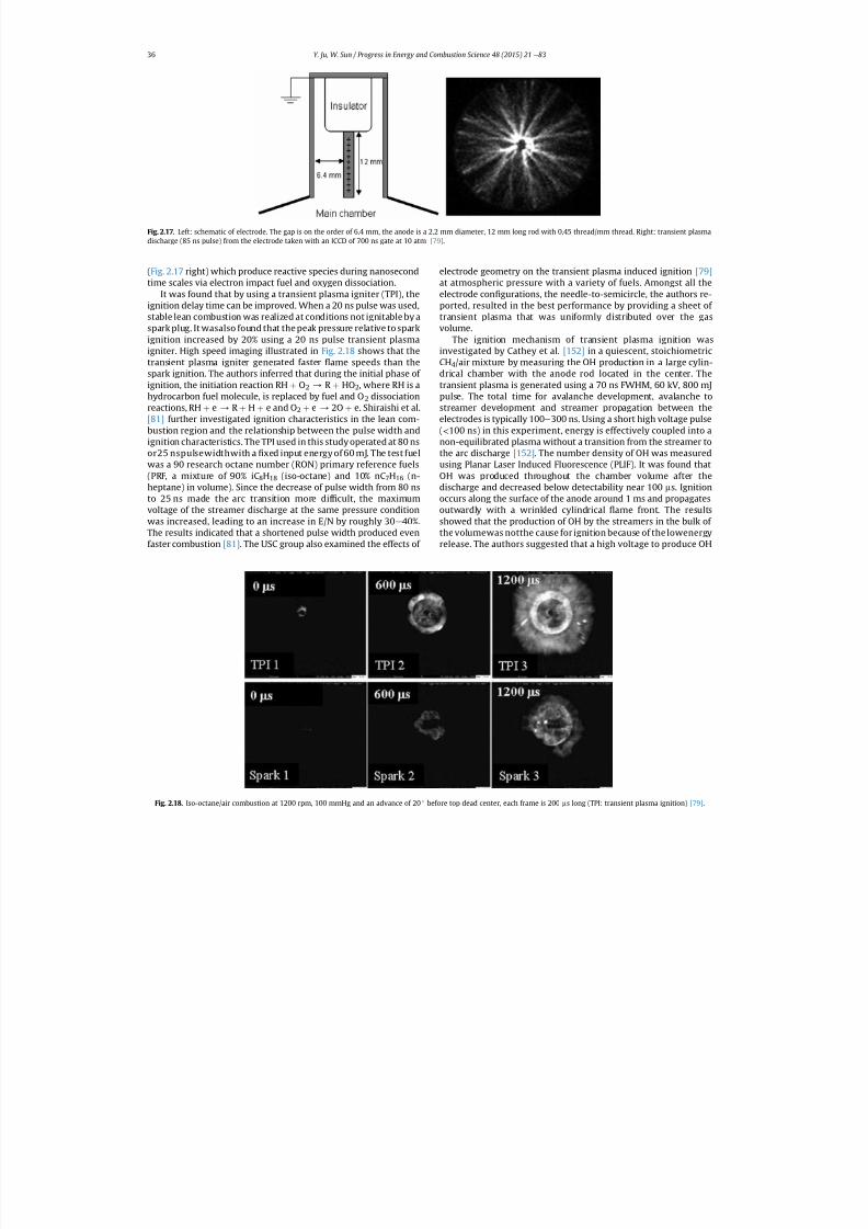
7/21/2019 Plasma Assisted Combustion Dynamics and Chemistry
http://slidepdf.com/reader/full/plasma-assisted-combustion-dynamics-and-chemistry 16/63
(Fig. 2.17 right) which produce reactive species during nanosecondtime scales via electron impact fuel and oxygen dissociation.
It was found that by using a transient plasma igniter (TPI), theignition delay time can be improved. When a 20 ns pulse was used,stable lean combustion was realized at conditions not ignitable by aspark plug. It wasalso found that the peak pressure relative to sparkignition increased by 20% using a 20 ns pulse transient plasmaigniter. High speed imaging illustrated in Fig. 2.18 shows that thetransient plasma igniter generated faster ame speeds than thespark ignition. The authors inferred that during the initial phase of ignition, the initiation reaction RH þ O2 / R þ HO2, where RH is ahydrocarbon fuel molecule, is replaced by fuel and O 2 dissociationreactions, RH þ e / R þ H þ e and O 2 þ e / 2O þ e. Shiraishi et al.[81] further investigated ignition characteristics in the lean com-bustion region and the relationship between the pulse width andignition characteristics. The TPI used in this study operated at 80 nsor25 nspulsewidthwith a xed input energy of 60 mJ. The test fuelwas a 90 research octane number (RON) primary reference fuels(PRF, a mixture of 90% iC 8H18 (iso-octane) and 10% nC 7H16 (n-heptane) in volume). Since the decrease of pulse width from 80 nsto 25 ns made the arc transition more dif cult, the maximumvoltage of the streamer discharge at the same pressure conditionwas increased, leading to an increase in E/N by roughly 30 e 40%.The results indicated that a shortened pulse width produced evenfaster combustion [81] . The USC group also examined the effects of
electrode geometry on the transient plasma induced ignition [79]at atmospheric pressure with a variety of fuels. Amongst all theelectrode con gurations, the needle-to-semicircle, the authors re-ported, resulted in the best performance by providing a sheet of transient plasma that was uniformly distributed over the gasvolume.
The ignition mechanism of transient plasma ignition wasinvestigated by Cathey et al. [152] in a quiescent, stoichiometricCH4/air mixture by measuring the OH production in a large cylin-drical chamber with the anode rod located in the center. Thetransient plasma is generated using a 70 ns FWHM, 60 kV, 800 mJpulse. The total time for avalanche development, avalanche tostreamer development and streamer propagation between theelectrodes is typically 100 e 300 ns. Using a short high voltage pulse(< 100 ns) in this experiment, energy is effectively coupled into anon-equilibrated plasma without a transition from the streamer tothe arc discharge [152] . The number density of OH was measuredusing Planar Laser Induced Fluorescence (PLIF). It was found thatOH was produced throughout the chamber volume after thedischarge and decreased below detectability near 100 ms. Ignitionoccurs along the surface of the anode around 1 ms and propagatesoutwardly with a wrinkled cylindrical ame front. The resultsshowed that the production of OH by the streamers in the bulk of the volumewas notthe cause for ignition because of the lowenergyrelease. The authors suggested that a high voltage to produce OH
Fig. 2.17. Left: schematic of electrode. The gap is on the order of 6.4 mm, the anode is a 2.2 mm diameter, 12 mm long rod with 0.45 thread/mm thread. Right: transient plasmadischarge (85 ns pulse) from the electrode taken with an ICCD of 700 ns gate at 10 atm [79] .
Fig. 2.18. Iso-octane/air combustion at 1200 rpm, 100 mmHg and an advance of 20 before top dead center, each frame is 200 ms long (TPI: transient plasma ignition) [79] .
Y. Ju, W. Sun / Progress in Energy and Combustion Science 48 (2015) 21 e 8336
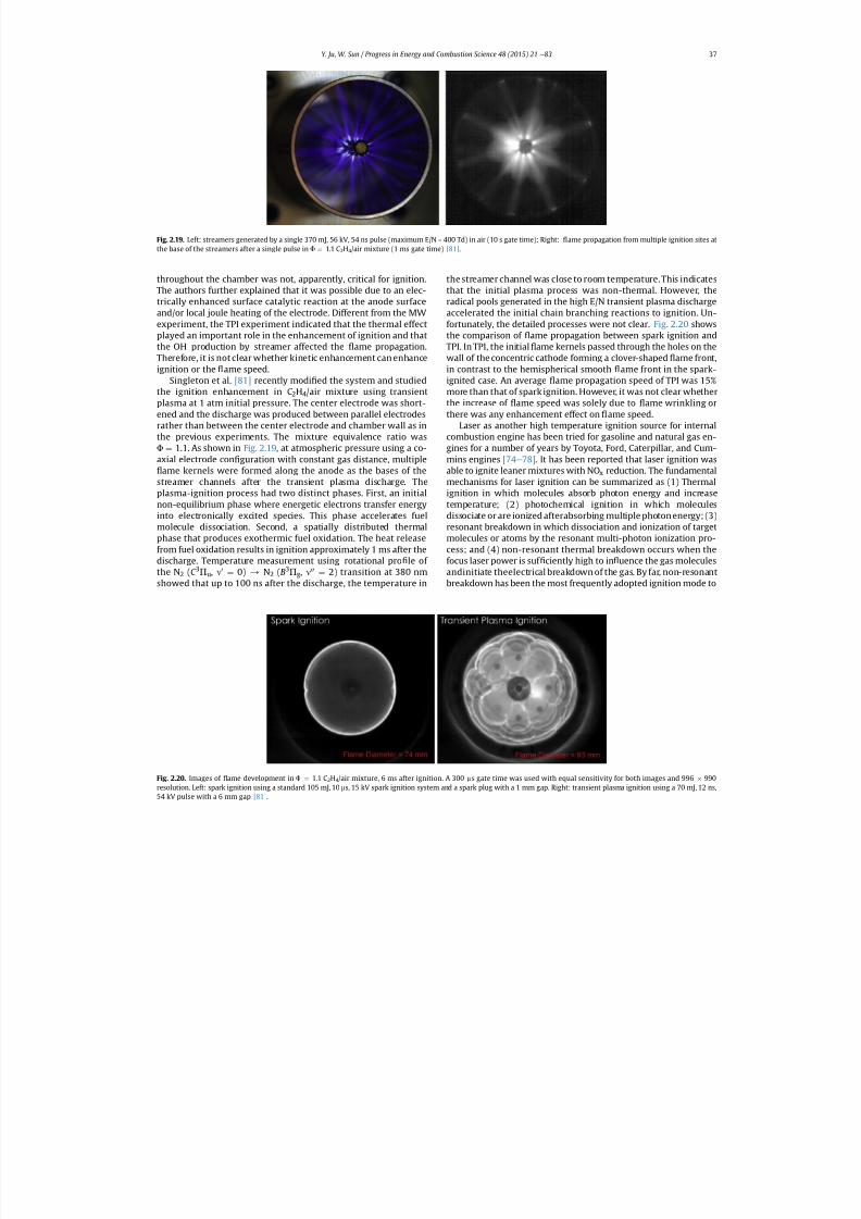
7/21/2019 Plasma Assisted Combustion Dynamics and Chemistry
http://slidepdf.com/reader/full/plasma-assisted-combustion-dynamics-and-chemistry 17/63
throughout the chamber was not, apparently, critical for ignition.The authors further explained that it was possible due to an elec-trically enhanced surface catalytic reaction at the anode surfaceand/or local joule heating of the electrode. Different from the MWexperiment, the TPI experiment indicated that the thermal effectplayed an important role in the enhancement of ignition and thatthe OH production by streamer affected the ame propagation.Therefore, it is not clear whether kinetic enhancement can enhanceignition or the ame speed.
Singleton et al. [81] recently modi ed the system and studiedthe ignition enhancement in C 2H4/air mixture using transientplasma at 1 atm initial pressure. The center electrode was short-ened and the discharge was produced between parallel electrodesrather than between the center electrode and chamber wall as inthe previous experiments. The mixture equivalence ratio wasF ¼ 1.1. As shown in Fig. 2.19 , at atmospheric pressure using a co-axial electrode con guration with constant gas distance, multiple
ame kernels were formed along the anode as the bases of thestreamer channels after the transient plasma discharge. Theplasma-ignition process had two distinct phases. First, an initialnon-equilibrium phase where energetic electrons transfer energyinto electronically excited species. This phase accelerates fuelmolecule dissociation. Second, a spatially distributed thermalphase that produces exothermic fuel oxidation. The heat releasefrom fuel oxidation results in ignition approximately 1 ms after thedischarge. Temperature measurement using rotational pro le of the N 2 (C 3P u , n0 ¼ 0) / N2 (B3P g, n00 ¼ 2) transition at 380 nmshowed that up to 100 ns after the discharge, the temperature in
the streamer channel was close to room temperature. This indicatesthat the initial plasma process was non-thermal. However, theradical pools generated in the high E/N transient plasma dischargeaccelerated the initial chain branching reactions to ignition. Un-fortunately, the detailed processes were not clear. Fig. 2.20 showsthe comparison of ame propagation between spark ignition andTPI. In TPI, the initial ame kernels passed through the holes on thewall of the concentric cathode forming a clover-shaped ame front,in contrast to the hemispherical smooth ame front in the spark-ignited case. An average ame propagation speed of TPI was 15%more than that of spark ignition. However, it was not clear whetherthe increase of ame speed was solely due to ame wrinkling orthere was any enhancement effect on ame speed.
Laser as another high temperature ignition source for internalcombustion engine has been tried for gasoline and natural gas en-gines for a number of years by Toyota, Ford, Caterpillar, and Cum-mins engines [74 e 78] . It has been reported that laser ignition wasable to ignite leaner mixtures with NO x reduction. The fundamentalmechanisms for laser ignition can be summarized as (1) Thermalignition in which molecules absorb photon energy and increasetemperature; (2) photochemical ignition in which moleculesdissociate or are ionized afterabsorbing multiple photon energy; (3)resonant breakdown in which dissociation and ionization of targetmolecules or atoms by the resonant multi-photon ionization pro-cess; and (4) non-resonant thermal breakdown occurs when thefocus laser power is suf ciently high to in uence the gas moleculesandinitiate theelectrical breakdown of the gas. By far, non-resonantbreakdown has been the most frequently adopted ignition mode to
Fig. 2.20. Images of ame development in F ¼ 1.1 C2H4/air mixture, 6 ms after ignition. A 300 ms gate time was used with equal sensitivity for both images and 996 990resolution. Left: spark ignition using a standard 105 mJ, 10 ms, 15 kV spark ignition system and a spark plug with a 1 mm gap. Right: transient plasma ignition using a 70 mJ, 12 ns,
54 kV pulse with a 6 mm gap [81] .
Fig. 2.19. Left: streamers generated by a single 370 mJ, 56 kV, 54 ns pulse (maximum E/N ~ 400 Td) in air (10 s gate time); Right: ame propagation from multiple ignition sites atthe base of the streamers after a single pulse in F ¼ 1.1 C2H4/air mixture (1 ms gate time) [81] .
Y. Ju, W. Sun / Progress in Energy and Combustion Science 48 (2015) 21 e 83 37
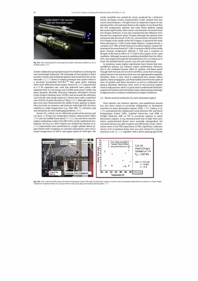
7/21/2019 Plasma Assisted Combustion Dynamics and Chemistry
http://slidepdf.com/reader/full/plasma-assisted-combustion-dynamics-and-chemistry 18/63
initiate combustion primarily because of its freedom in selecting thelaser wavelength andpower. The advantage of laser ignition is that itprovides remote and multipoint ignition and avoids heat loss to theelectrode. Fig. 2.21 shows a compact prototype laser igniter which isa passively Q-switched Nd:YAG/ Cr4þ :YAG giant pulse emittingmicro-laser with three beam output. Pavel et al. [200] reported thatat a 5 Hz repetition rate, each line delivered laser pulses withapproximately 2.4 mJ energy and 2.8 MW peak power within thepulse duration. Recently, Princeton Optronics developed VerticalCavity Surface Emitting Laser (VCSEL) and increased the ef ciency(up to 63.4%) and energy output to 7 mJ per pulse with a repetitionrate of 20 Hz at pulse duration of 100 ms [201] . Although many en-gine tests have demonstrated the ability of laser ignition to igniteultra-lean fuel-air mixtures and mixtures with high EGR, the laserstability at a high temperature (e.g., 200 e 400 C), vibration, and
soot formation are still challenging problems [201] .Ozone (O 3), which can be ef ciently produced by plasma and
can have a strong low temperature kinetic enhancement effect[108] and can modify ame speed [157,202] , has also been used forengine combustion control. The effect of O 3 on the combustion of n-heptane (nC 7H16) in a HCCI engine was studied by Foucher et al.[179] . Experiments were performed in a single cylinder diesel en-gine fueled with n-heptane at constant equivalence ratio of 0.3,intake temperature of 300 K, and engine speed of 1500 rpm. The
intake manifold was seeded by ozone produced by a dielectricbarrier discharge reactor. Experimental results showed that lowozone concentrations ( < 50 ppm) have an important impact on thephasing of the cool and main ame in the engine. It was found thatthe low temperature ignition and main ame ignition timingdecreased signi cantly when ozone concentration increased from0 to 20 ppm. However, it was also reported that the in uence of O 3became less important above 20 ppm although the ignition timemonotonically decreased. If the O 3 concentration increased from0 to 54 ppm at the intake of the HCCI engine, it advanced the main
ame phasing by 7 CAD (Crank Angle Degree). Comparatively, avariation of 0 e 60% of EGR (Exhaust Gas Recirculation) retards thephasing of the main ame by7 CAD.A variation of60 K oftheintakegases mixture temperature affected 3 CAD and a variation of 49 ppm of NO had an effect of 1.5 CAD in this engine at the samecondition. Although numerical modeling identi ed that the effectof O 3 was majorly through the decomposition of O 3 to release an Oatom, the detailed kinetic process was not well understood.
In summary, many engine experiments have shown that non-equilibrium plasma can enhance engine performance. However,due to the combined plasma effect on ignition and ame speedthrough both thermal and non-thermaleffects, some observed large-enhancement in the leanburn limit wasnot appropriatelyexplained.Therefore, there is clear need to understand how plasma affectsignition, ame propagation, and ammability limit from the point of view of ignition and ame dynamics as well as combustion andplasma chemistry. Moreover, since most of the practical engineswork at high pressure, there is a great need to understand thekineticpropertiesof plasma andto developa large volumeplasma dischargeat high pressure to enhance combustion at engine conditions.
2.3. Plasma assisted combustion for pulse detonation engines
Since plasma can enhance ignition, non-equilibrium plasmahas also been tested to accelerate de agration to detonationtransition in pulse detonation engines (PDE) [203] . Cathey et al.
[178] summarized the collaborative work between USC and NavalPostgraduate School (NPS), Stanford University, and AFRL atWright e Patterson AFB on TPI to accelerate ignition in pulsedetonation engines. It was demonstrated that at high ow rateswhere spark-initiated ames were normally extinguished, thetransient plasma was able to ignite and effectively create a deto-nation wave in the PDE experiment at NPS. Signi cant reduction(factor of 4) in ignition delay time was also shown for C 2H4/airmixtures as in Fig. 2.22 together with a direct photograph of the
Fig. 2.22. Left: a valve less PDE setup at the Naval Postgraduate School. This type of architecture requires a booster and its anticipated applications are missiles or rockets. Right:
comparison of ignition delays for C 2H4/air mixture using spark plug and transient plasma igniter [178] .
Fig. 2.21. Direct photograph of a prototype laser igniter showing breakdown in air atmultiple points [200] .
Y. Ju, W. Sun / Progress in Energy and Combustion Science 48 (2015) 21 e 8338
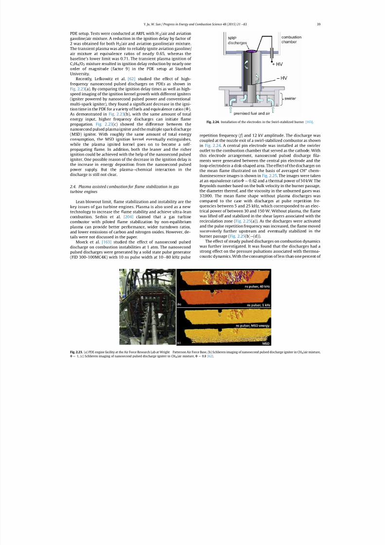
7/21/2019 Plasma Assisted Combustion Dynamics and Chemistry
http://slidepdf.com/reader/full/plasma-assisted-combustion-dynamics-and-chemistry 19/63
PDE setup. Tests were conducted at ARFL with H 2/air and aviationgasoline/air mixture. A reduction in the ignition delay by factor of 2 was obtained for both H 2/air and aviation gasoline/air mixture.The transient plasma was able to reliably ignite aviation gasoline/air mixture at equivalence ratios of nearly 0.65, whereas thebaseline's lower limit was 0.71. The transient plasma ignition of C2H4/O2 mixture resulted in ignition delay reduction by nearly oneorder of magnitude (factor 9) in the PDE setup at StanfordUniversity.
Recently, Lefkowitz et al. [62] studied the effect of high-frequency nanosecond pulsed discharges on PDEs as shown inFig. 2.23 (a). By comparing the ignition delay times as well as high-speed imaging of the ignition kernel growth with different igniters(igniter powered by nanosecond pulsed power and conventionalmulti-spark igniter), they found a signi cant decrease in the igni-tion time in the PDE for a variety of fuels and equivalence ratios ( F ).As demonstrated in Fig. 2.23 (b), with the same amount of totalenergy input, higher frequency discharges can initiate amepropagation. Fig. 2.23 (c) showed the difference between thenanosecond pulsed plasma igniter and the multiple spark discharge(MSD) igniter. With roughly the same amount of total energyconsumption, the MSD ignition kernel eventually extinguishes,while the plasma ignited kernel goes on to become a self-propagating ame. In addition, both the leaner and the richerignition could be achieved with the help of the nanosecond pulsedigniter. One possible reason of the decrease in the ignition delay isthe increase in energy deposition from the nanosecond pulsedpower supply. But the plasma e chemical interaction in thedischarge is still not clear.
2.4. Plasma assisted combustion for ame stabilization in gasturbine engines
Lean blowout limit, ame stabilization and instability are thekey issues of gas turbine engines. Plasma is also used as a newtechnology to increase the ame stability and achieve ultra-leancombustion. Serbin et al. [204] claimed that a gas turbinecombustor with piloted ame stabilization by non-equilibriumplasma can provide better performance, wider turndown ratios,and lower emissions of carbon and nitrogen oxides. However, de-tails were not discussed in the paper.
Moeck et al. [163] studied the effect of nanosecond pulseddischarge on combustion instabilities at 1 atm. The nanosecondpulsed discharges were generated by a solid state pulse generator(FID 300-100MC4K) with 10 ns pulse width at 10 e 80 kHz pulse
repetition frequency ( f ) and 12 kV amplitude. The discharge wascoupled at the nozzle exit of a swirl-stabilized combustor as shownin Fig. 2.24 . A central pin electrode was installed at the swirleroutlet to the combustion chamber that served as the cathode. Withthis electrode arrangement, nanosecond pulsed discharge la-ments were generated between the central pin electrode and theloop-electrodein a disk-shaped area. The effect of the discharges onthe mean ame illustrated on the basis of averaged CH* chem-iluminescence images is shown in Fig. 2.25 . The images were takenat an equivalence ratio F ¼ 0.62 and a thermal power of 50 kW. TheReynolds number based on the bulk velocity in the burner passage,the diameter thereof, and the viscosity in the unburned gases was37,000. The mean ame shape without plasma discharges wascompared to the case with discharges at pulse repetition fre-quencies between 5 and 25 kHz, which corresponded to an elec-trical power of between 30 and 150 W. Without plasma, the amewas lifted off and stabilized in the shear layers associated with therecirculation zone ( Fig. 2.25 (a)). As the discharges were activatedand the pulse repetition frequency was increased, the ame movedsuccessively further upstream and eventually stabilized in theburner passage ( Fig. 2.25 (b) e (d)).
The effect of steady pulsed discharges on combustion dynamicswas further investigated. It was found that the discharges had astrong effect on the pressure pulsations associated with thermoa-coustic dynamics. With the consumption of less than one percent of
Fig. 2.23. (a) PDE engine facility at the Air Force Research Lab at Wright e Patterson Air Force Base, (b) Schlieren imaging of nanosecond pulsed discharge igniter in CH 4/air mixture,
F ¼
1, (c) Schlieren imaging of nanosecond pulsed discharge igniter in CH 4/air mixture, F ¼
0.8 [62] .
Fig. 2.24. Installation of the electrodes in the Swirl-stabilized burner [163] .
Y. Ju, W. Sun / Progress in Energy and Combustion Science 48 (2015) 21 e 83 39
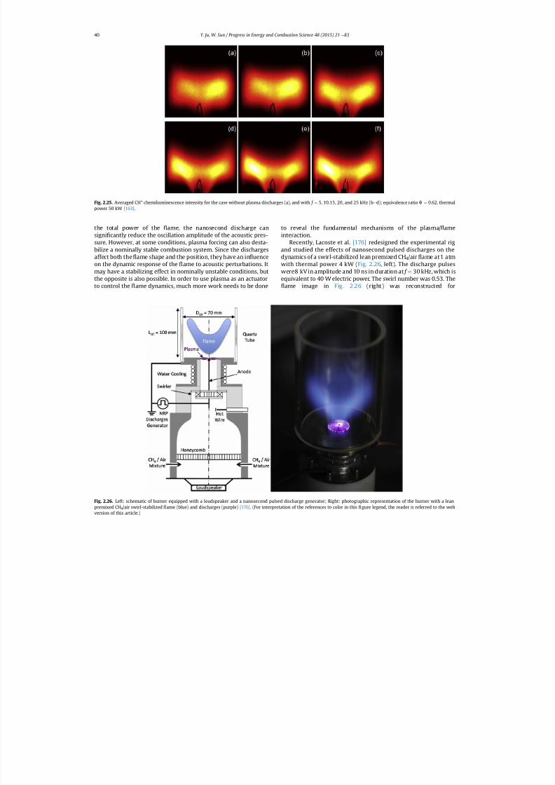
7/21/2019 Plasma Assisted Combustion Dynamics and Chemistry
http://slidepdf.com/reader/full/plasma-assisted-combustion-dynamics-and-chemistry 20/63
the total power of the ame, the nanosecond discharge cansigni cantly reduce the oscillation amplitude of the acoustic pres-sure. However, at some conditions, plasma forcing can also desta-bilize a nominally stable combustion system. Since the dischargesaffect both the ame shape and the position, they have an in uenceon the dynamic response of the ame to acoustic perturbations. Itmay have a stabilizing effect in nominally unstable conditions, butthe opposite is also possible. In order to use plasma as an actuatorto control the ame dynamics, much more work needs to be done
to reveal the fundamental mechanisms of the plasma/ ameinteraction.
Recently, Lacoste et al. [176] redesigned the experimental rigand studied the effects of nanosecond pulsed discharges on thedynamics of a swirl-stabilized lean premixed CH 4/air ame at1 atmwith thermal power 4 kW ( Fig. 2.26 , left). The discharge pulseswere8 kV in amplitude and 10 ns in duration at f ¼ 30 kHz, which isequivalent to 40 W electric power. The swirl number was 0.53. The
ame image in Fig. 2.26 (right) was reconstructed for
Fig. 2.26. Left: schematic of burner equipped with a loudspeaker and a nanosecond pulsed discharge generator; Right: photographic representation of the burner with a leanpremixed CH 4/air swirl-stabilized ame (blue) and discharges (purple) [176] . (For interpretation of the references to color in this gure legend, the reader is referred to the web
version of this article.)
Fig. 2.25. Averaged CH* chemiluminescence intensity for the case without plasma discharges (a), and with f ¼ 5, 10,15, 20, and 25 kHz (b e d); equivalence ratio F ¼ 0.62, thermalpower 50 kW [163] .
Y. Ju, W. Sun / Progress in Energy and Combustion Science 48 (2015) 21 e 8340
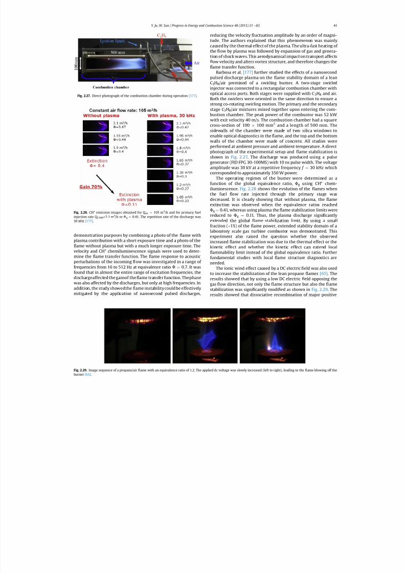
7/21/2019 Plasma Assisted Combustion Dynamics and Chemistry
http://slidepdf.com/reader/full/plasma-assisted-combustion-dynamics-and-chemistry 21/63
demonstration purposes by combining a photo of the ame withplasma contribution with a short exposure time and a photo of the
ame without plasma but with a much longer exposure time. Thevelocity and CH* chemiluminescence signals were used to deter-mine the ame transfer function. The ame response to acousticperturbations of the incoming ow was investigated in a range of frequencies from 16 to 512 Hz at equivalence ratio F ¼ 0.7. It wasfound that in almost the entire range of excitation frequencies, thedischargeaffected the gainof the ame transfer function. Thephasewas also affected by the discharges, but only at high frequencies. Inaddition, the study showedthe ame instabilitycouldbe effectivelymitigated by the application of nanosecond pulsed discharges,
reducing the velocity uctuation amplitude by an order of magni-tude. The authors explained that this phenomenon was mainlycaused by the thermal effect of the plasma. The ultra-fast heating of the ow by plasma was followed by expansion of gas and genera-tion of shock waves. This aerodynamical impact on transport affects
ow velocity and alters vortex structure, and therefore changes theame transfer function.
Barbosa et al. [177] further studied the effects of a nanosecondpulsed discharge plasma on the ame stability domain of a leanC3H8/air premixed of a swirling burner. A two-stage swirledinjector was connected to a rectangular combustion chamber withoptical access ports. Both stages were supplied with C 3H8 and air.Both the swirlers were oriented in the same direction to ensure astrong co-rotating swirling motion. The primary and the secondarystage C 3H8/air mixtures mixed together upon entering the com-bustion chamber. The peak power of the combustor was 52 kWwith exit velocity 40 m/s. The combustion chamber had a squarecross-section of 100 100 mm 2 and a length of 500 mm. Thesidewalls of the chamber were made of two silica windows toenable optical diagnostics in the ame, and the top and the bottomwalls of the chamber were made of concrete. All studies wereperformed at ambient pressure and ambient temperature. A directphotograph of the experimental setup and ame stabilization isshown in Fig. 2.27. The discharge was produced using a pulsegenerator (FID FPG 30-100MS) with 10 ns pulse width. The voltageamplitude was 30 kV at a repetitive frequency f ¼ 30 kHz whichcorresponded to approximately 350 W power.
The operating regimes of the burner were determined as afunction of the global equivalence ratio, F g using CH* chem-iluminescence. Fig. 2.28 shows the evolution of the ames whenthe fuel ow rate injected through the primary stage wasdecreased. It is clearly showing that without plasma, the ameextinction was observed when the equivalence ratios reachedF g ¼ 0.41, whereas using plasma the ame stabilization limits werereduced to F g ¼ 0.11. Thus, the plasma discharge signi cantlyextended the global ame stabilization limit. By using a small
fraction (~1%) of the ame power, extended stability domain of alaboratory scale gas turbine combustor was demonstrated. Thisexperiment also raised the question whether the observedincreased ame stabilization was due to the thermal effect or thekinetic effect and whether the kinetic effect can extend local
ammability limit instead of the global equivalence ratio. Furtherfundamental studies with local ame structure diagnostics areneeded.
The ionic wind effect caused by a DC electric eld was also usedto increase the stabilization of the lean propane ames [65] . Theresults showed that by using a low DC electric eld opposing thegas ow direction, not only the ame structure but also the amestabilization was signi cantly modi ed as shown in Fig. 2.29 . Theresults showed that dissociative recombination of major positive
Fig. 2.29. Image sequence of a propane/air ame with an equivalence ratio of 1.2. The applied dc voltage was slowly increased (left to right), leading to the ame blowing off the
burner [65] .
Fig. 2.27. Direct photograph of the combustion chamber during operation [177] .
Fig. 2.28. CH* emission images obtained for Q air ¼ 105 m 3/h and for primary fuelinjection rate Q C3H8 < 2.1 m 3/h or F g < 0.41. The repetition rate of the discharge was30 kHz [177] .
Y. Ju, W. Sun / Progress in Energy and Combustion Science 48 (2015) 21 e 83 41
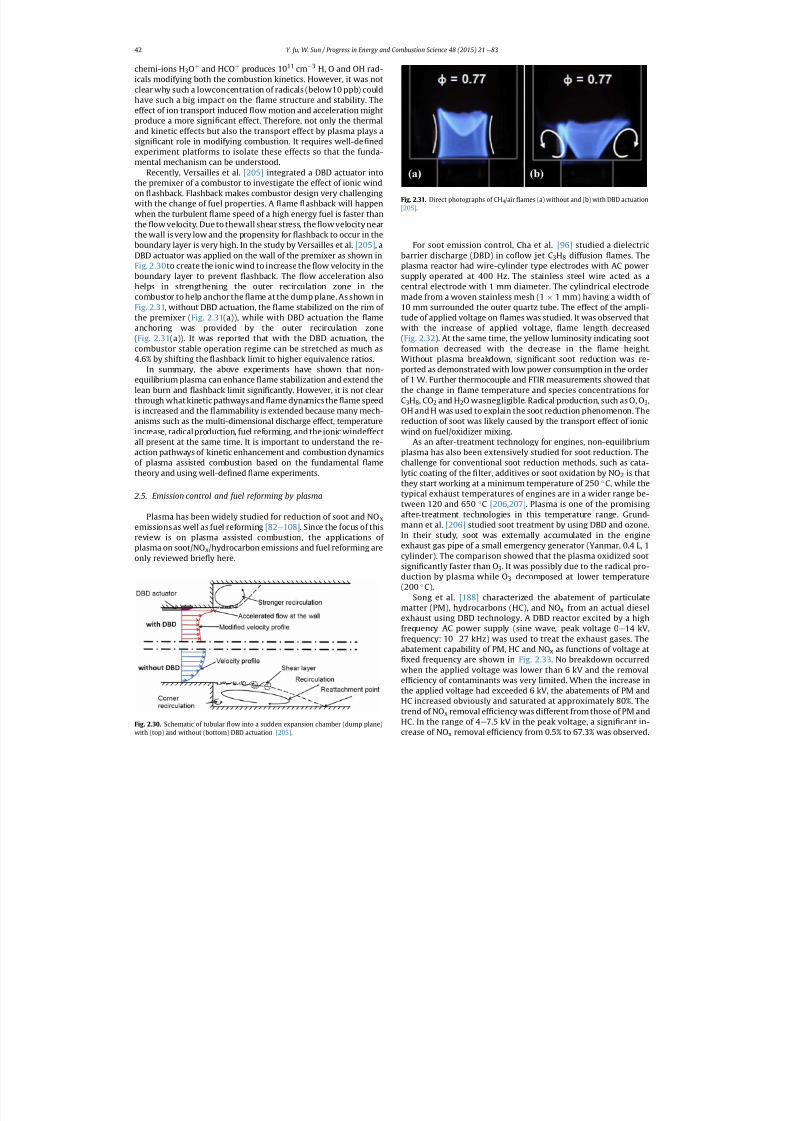
7/21/2019 Plasma Assisted Combustion Dynamics and Chemistry
http://slidepdf.com/reader/full/plasma-assisted-combustion-dynamics-and-chemistry 22/63
chemi-ions H 3Oþ and HCO þ produces 10 11 cm 3 H, O and OH rad-icals modifying both the combustion kinetics. However, it was notclear why such a lowconcentration of radicals (below10 ppb) couldhave such a big impact on the ame structure and stability. Theeffect of ion transport induced ow motion and acceleration mightproduce a more signi cant effect. Therefore, not only the thermaland kinetic effects but also the transport effect by plasma plays asigni cant role in modifying combustion. It requires well-de nedexperiment platforms to isolate these effects so that the funda-mental mechanism can be understood.
Recently, Versailles et al. [205] integrated a DBD actuator intothe premixer of a combustor to investigate the effect of ionic windon ashback. Flashback makes combustor design very challengingwith the change of fuel properties. A ame ashback will happenwhen the turbulent ame speed of a high energy fuel is faster thanthe ow velocity. Due to thewall shear stress, the ow velocity nearthe wall is very low and the propensity for ashback to occur in theboundary layer is very high. In the study by Versailles et al. [205] , aDBD actuator was applied on the wall of the premixer as shown inFig. 2.30 to create the ionic wind to increase the ow velocity in theboundary layer to prevent ashback. The ow acceleration alsohelps in strengthening the outer recirculation zone in thecombustor to help anchor the ame at the dump plane. As shown inFig. 2.31 , without DBD actuation, the ame stabilized on the rim of the premixer ( Fig. 2.31 (a)), while with DBD actuation the ameanchoring was provided by the outer recirculation zone(Fig. 2.31 (a)). It was reported that with the DBD actuation, thecombustor stable operation regime can be stretched as much as4.6% by shifting the ashback limit to higher equivalence ratios.
In summary, the above experiments have shown that non-equilibrium plasma can enhance ame stabilization and extend thelean burn and ashback limit signi cantly. However, it is not clearthrough what kinetic pathways and ame dynamics the ame speedis increased and the ammability is extended because many mech-anisms such as the multi-dimensional discharge effect, temperatureincrease, radicalproduction, fuel reforming,and the ionic windeffect
all present at the same time. It is important to understand the re-action pathways of kinetic enhancement and combustion dynamicsof plasma assisted combustion based on the fundamental ametheory and using well-de ned ame experiments.
2.5. Emission control and fuel reforming by plasma
Plasma has been widely studied for reduction of soot and NO xemissions as well as fuel reforming [82 e 108] . Since the focus of thisreview is on plasma assisted combustion, the applications of plasma on soot/NO x/hydrocarbon emissions and fuel reforming areonly reviewed brie y here.
For soot emission control, Cha et al. [96] studied a dielectricbarrier discharge (DBD) in co ow jet C 3H8 diffusion ames. Theplasma reactor had wire-cylinder type electrodes with AC powersupply operated at 400 Hz. The stainless steel wire acted as acentral electrode with 1 mm diameter. The cylindrical electrodemade from a woven stainless mesh (1 1 mm) having a width of 10 mm surrounded the outer quartz tube. The effect of the ampli-tude of applied voltage on ames was studied. It was observed thatwith the increase of applied voltage, ame length decreased(Fig. 2.32 ). At the same time, the yellow luminosity indicating sootformation decreased with the decrease in the ame height.Without plasma breakdown, signi cant soot reduction was re-ported as demonstrated with low power consumption in the orderof 1 W. Further thermocouple and FTIR measurements showed thatthe change in ame temperature and species concentrations forC3H8, CO2 and H 2O wasnegligible. Radical production, such as O, O 3,OH and H was used to explain the soot reduction phenomenon. Thereduction of soot was likely caused by the transport effect of ionicwind on fuel/oxidizer mixing.
As an after-treatment technology for engines, non-equilibriumplasma has also been extensively studied for soot reduction. Thechallenge for conventional soot reduction methods, such as cata-lytic coating of the lter, additives or soot oxidation by NO 2 is thatthey start working at a minimum temperature of 250 C, while thetypical exhaust temperatures of engines are in a wider range be-tween 120 and 650 C [206,207] . Plasma is one of the promisingafter-treatment technologies in this temperature range. Grund-mann et al. [206] studied soot treatment by using DBD and ozone.In their study, soot was externally accumulated in the engineexhaust gas pipe of a small emergency generator (Yanmar, 0.4 L, 1cylinder). The comparison showed that the plasma oxidized sootsigni cantly faster than O 3. It was possibly due to the radical pro-duction by plasma while O 3 decomposed at lower temperature
(200
C).Song et al. [188] characterized the abatement of particulate
matter (PM), hydrocarbons (HC), and NO x from an actual dieselexhaust using DBD technology. A DBD reactor excited by a highfrequency AC power supply (sine wave, peak voltage 0 e 14 kV,frequency: 10 e 27 kHz) was used to treat the exhaust gases. Theabatement capability of PM, HC and NO x as functions of voltage at
xed frequency are shown in Fig. 2.33 . No breakdown occurredwhen the applied voltage was lower than 6 kV and the removalef ciency of contaminants was very limited. When the increase inthe applied voltage had exceeded 6 kV, the abatements of PM andHC increased obviously and saturated at approximately 80%. Thetrend of NO x removal ef ciency was different from those of PM andHC. In the range of 4 e 7.5 kV in the peak voltage, a signi cant in-
crease of NO x removal ef ciency from 0.5% to 67.3% was observed.
Fig. 2.30. Schematic of tubular ow into a sudden expansion chamber (dump plane)
with (top) and without (bottom) DBD actuation [205] .
Fig. 2.31. Direct photographs of CH 4/air ames (a) without and (b) with DBD actuation[205] .
Y. Ju, W. Sun / Progress in Energy and Combustion Science 48 (2015) 21 e 8342
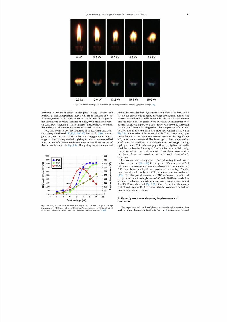
7/21/2019 Plasma Assisted Combustion Dynamics and Chemistry
http://slidepdf.com/reader/full/plasma-assisted-combustion-dynamics-and-chemistry 23/63
However, a further increase in the peak voltage lowered theremoval ef ciency. A possible reason was the dissociation of N 2 toform NO x owing to the increase in E/N. The authors also reportedthe abatements of various alkanes and polycyclic aromatic hydro-carbons (PAHs) including alkanes, alkenes, and aromatics. However,the underlying abatement mechanisms are still missing.
NOx and hydrocarbon reduction by gliding arc has also beenextensively conducted [82,83,91,99,189] . Lee et al. [189] investi-gated NO x reduction in industrial burners using gliding arc. A rststage combustor integrated with gliding arc plasma was embeddedwith the head of the commercial reference burner. The schematic of the burner is shown in Fig. 2.34 . The gliding arc was convected
downward with the uid-dynamic rotation of reactant ow. Liquidnature gas (LNG) was supplied through the bottom hole of thereactor, where it was rapidly mixed with air and allowed to enterinto the arc region. The plasma used AC power with a frequency of 10 kHz corresponding to powers 50 e 150 W which were a value lessthan 0.1% of the fuel heating value. The comparison of NO x pro-duction rate in the reference and modi ed burners is shown inFig. 2.35 as a function of the excess air ratio. The direct photographsof the ame from the two burners were also embedded. Signi cantNOx reduction was observed. The rst stage combustor operated asa reformer that could host a partial oxidation process, producinghydrogen rich (10% in volume) syngas ow that ignited and stabi-lized the combustion ame apart from the burner rim. Ultimately,the enhanced mixing and removal of hot ame zone with abroadened ame area acted as the main mechanisms of NO xreduction.
Plasma has been widely used in fuel reforming, in addition toemission reduction [98 e 106] . Recently, two different types of fuelreformers, the nanosecond spark discharge and the nanosecond
DBD have been developed for propane-air reforming. For thenanosecond spark discharge, 70% fuel conversion was obtained[208] . For the pulsed nanosecond DBD reformer, the effect of temperature on reforming between 900 and 1300 K was studied. Asigni cant in uence on mixture conversion ef ciency, especially atT ¼ 900 K, was obtained ( Fig. 2.36 ). It was found that the energycost of hydrogen for DBD reformer is higher compared to that fornanosecond spark reformer.
3. Flame dynamics and chemistry in plasma assistedcombustion
The experimental results of plasma assisted engine combustion
and turbulent
ame stabilization in Section 2 sometimes showed
Fig. 2.32. Direct photographs of ame with 0.5 s exposure time by varying applied voltage [96] .
Fig. 2.33. PM, HC and NOx removal ef ciencies as a function of peak voltage(frequency ¼ 15.5 kHz, engine load ¼ 50%, initial PM concentration ¼ 73.67 mg/L, initial
HC concentration ¼
107.6 ppm, initial NO x concentration ¼
476.3 ppm) [188] .
Y. Ju, W. Sun / Progress in Energy and Combustion Science 48 (2015) 21 e 83 43
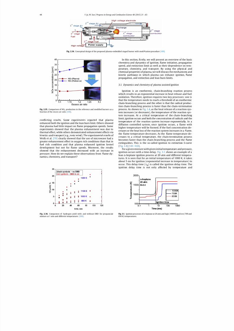
7/21/2019 Plasma Assisted Combustion Dynamics and Chemistry
http://slidepdf.com/reader/full/plasma-assisted-combustion-dynamics-and-chemistry 24/63
con icting results. Some experiments reported that plasmaenhanced both the ignition and the lean burn limit. Others showedthat plasma had little impact on ame propagation speeds. Some
experiments showed that the plasma enhancement was due tothermal effect, while others demonstrated enhancement effects viakinetics and transport (e.g., ionic wind). The experimental results of Wolk et al. [70] clearly showed that the use of microwave had agreater enhancement effect in oxygen rich conditions than that infuel rich condition and that plasma enhanced ignition kerneldevelopment but not for ame speeds. Moreover, the resultsshowed that the enhancement decreased with an increase inpressure. How do we explain these observations from ame dy-namics, chemistry, and transport?
In this section, rstly, we will present an overview of the basicchemistry and dynamics of ignition, ame initiation, propagationspeed, and extinction limit as well as their dependence on tem-perature, chemistry, and transport. By using the physical andchemical properties of plasma, we will discuss the mechanisms andkinetic pathways in which plasma can enhance ignition, amepropagation, and extinction and lean burn limits.
3.1. Dynamics and chemistry of plasma assisted ignition
Ignition is an exothermic, chain-branching reaction processwhich results in an exponential increase in heat release and fueloxidation. Therefore, ignition requires two key processes: one isthat the temperature needs to reach a threshold of an exothermicchain-branching process and the other is that the radical produc-tion chain-branching process is faster than the chain-terminationprocess. As shown in Fig. 1.4 , as the heat release of a reaction sys-tem increases (or decreases), the temperature of the reaction sys-tem increases. At a critical temperature of the chain-branchinglimit, ignition occurs and both the concentration of radicals and thetemperature of the reaction system increase exponentially. In adiffusion controlled system, once ignition occurs, a ame withhigher temperature will be formed. If the fuel concentration de-
creases or the heat loss of the reaction system increases in a ame,the ame temperature decreases. As the ame temperature de-creases to a critical temperature, the chain-termination processbecomes faster than the chain-branching process and the ameextinguishes. This is the so-called ignition to extinction S -curve(Fig. 1.4 ) [141 e 143] .
For a given mixture with given initial temperature and pressure,ignition occurs with a time delay. Fig. 3.1 shows an example of alean n-heptane ignition process at 20 atm and different tempera-tures. It is seen that for an initial temperature of 1000 K, it takesabout 5 ms for ignition (exponential increase in temperature) tooccur. This delay time ( t ig) is called the ignition delay time. Theignition delay time is not only affected by temperature and
Fig. 2.34. Conceptual design of the proposed plasma-embedded staged burner with modi cation procedure [189] .
Fig. 2.35. Comparison of NO x production in the reference and modi ed burners as afunction of the excess air ratio [189] .
Fig. 2.36. Comparison of hydrogen yield with and without DBD for propane/air
mixture at 1 atm and different temperatures [208] .
Fig. 3.1. Ignition processes of n-heptane at 20 atm and high (1000 K) and low (700 and
850 K) temperatures.
Y. Ju, W. Sun / Progress in Energy and Combustion Science 48 (2015) 21 e 8344

7/21/2019 Plasma Assisted Combustion Dynamics and Chemistry
http://slidepdf.com/reader/full/plasma-assisted-combustion-dynamics-and-chemistry 25/63
pressure, but also signi cantly by the fuel chemistry and the initiallevel of radicals.
Since hydrogen is the simplest combustion system, we rst usehydrogen as an example to understand how the chain-initiation,branching, and termination processes govern the ignition timeand explosion limit at different pressure and temperature rangesand to explain howradical production can enhance ignition. Table 3shows the important chain-initiation, branching, propagation, andtermination reactions as well as important plasma generatedradical production and NO x catalytic reactions of H 2/O2 system.Without plasma, the radicals (e.g., H and HO 2) are initially producedby a slow reaction (R1). After that, one H radical will generate tworadicals (OH and O) via the branching reaction (R2). Note that thereaction (R2) has a high activation energy and requires a hightemperature (~1100 K at 1 atm) to accelerate. Therefore, the pro-duced OH and O radicals quickly generate three H radicals via thechain-propagation reactions (R3) and (R4) (Fig. 3.2 , left), leading toan exponential increase in radical concentration for ignition.Therefore, at high temperature, one H radical produces three Hradicals via (R1) e (R4) and the ignition delay time is largelycontrolled by two slower reactions: (R1) and (R2) . As such, a small
radical production by plasma signi cantly shortens the ignitiondelay time by bypassing the chain initiation reaction (R1).
Fig. 3.2 (right) shows that radical addition into stoichiometricH2/O2 mixture at 1000 K reduces ignition delay time. It is seen thatonly 10 ppm radical addition of H by plasma shortens ignition timeby a factor of ve because radical addition by plasma bypasses theslowest chain-initiation reaction (R1) and provides the initial rad-icals directly for branching reaction (R2). In addition, it is inter-esting to note that atomic O radical addition is more effective thanH and OH in a H 2/O2 system. As seen in Fig. 3.2 (left), this is becauseadding one OH radical immediately produces one H radical viareaction (R4) since the reaction rate of chain-propagation reaction(R4) is much faster than that of (R2). So OH and H additions areequivalent. However, for one atomic O radical addition, as the re-action (R3) is also faster than (R2), 2H radicals are immediatelyproduced from reactions (R3) and (R4) . This is why adding atomic Oin a H 2/O2 system is more effective than adding H and OH forignition enhancement. Fortunately, non-equilibrium plasma is aneffective tool to produce atomic O via electron and excited nitrogenimpact dissociation reactions (e.g., (R8a) e (R8c) ) [43,148,161] .
At lower temperature and high pressure, radical production viabranching reaction (R2) is suppressed quickly by the terminationreaction (R7) and the reverse reaction of (R1), leading to theoccurrence of the second explosion limit [209,210] and a negativeburning rate dependence [211] on pressure due to the competitionbetween (R2) and (R7) ;
k 1 þ k52k 1
2k2k7 ½M
¼ 1 (3.1)
where k is the reaction rate constant and M is the third-bodyconcentration. If pressure further increases, the HO 2 concentra-tion formed by (R7) becomes so high that the reactions (R5) and(R6) become the main branching reaction pathways to produceOH radicals from HO 2 and H 2O2. These three different chain-
branching pathways at low, intermediate and high pressures leadto the three different explosion limits of the H 2/O2 system[141 e 143] . Fig. 3.3 shows that the three different H 2/O2 explosionlimits [212] (red dots (in the web version)) and the successfulignition conditions by plasma [213] . It is seen that without plasma,as discussed above, there are three pressure-dependent explosionlimits, low pressure limit, the second explosion limit, and the highpressure limit, controlled by reaction (R2), the competition be-tween reactions (R2) and (R7) , and the HO 2 and H 2O2 branching via(R5) and (R6) . It is interesting to note that with a plasma discharge,ignition can occur at a temperature below that of the explosionlimit. This is because the radical production by plasma via reactions
Fig. 3.2. Left: Schematic of the production process of three H radicals from one H radical in the H 2/O2 chain branching system. The line width here indicates the magnitude of the
reaction rate. Right: Ignition delay time decreases with the additions of different initial radicals (H, OH, O) in stoichiometric H 2/O2 system at 1000 K and 1 atm.
Table 3Key reactions in plasma assisted H 2/O2/N2 reaction system.
Chain-initiationH2 þ O2 ¼ HO2 þ H (R1)Chain-branching/propagationH þ O2 ¼ OH þ O (R2)O þ H2 ¼ OH þ H (R3)
OH þ H2 ¼ H2O þ H (R4)
HO2 þ H ¼ OH þ OH (R5)H2O2 ¼ OH þ OH (R6)
Chain-terminationH þ O2(þ M) ¼ HO2(þ M) (R7)HO2 þ H ¼ H2 þ O2 (R1)
Electron and N 2(*) impact dissociatione þ O2 ¼ O þ O(1D) (R8a)e þ O2
þ ¼ O þ O (R8b)
N2( A,B,C ) þ O2 ¼ O þ O þ N2 (R9a)
Nþ þ O2 ¼ Oþ þ NO (R9b)
Plasma activated reactionsH þ O2(1Dg) ¼ O þ OH (R10)O3 þ O2 ¼ O þ O2 þ O2 (R11)
O(1D) þ H2 ¼ OH þ H (R12)
NO catalytic branching NO þ HO2 ¼ NO2 þ HO (R13)H þ NO2 ¼ NO þ OH (R14)
Y. Ju, W. Sun / Progress in Energy and Combustion Science 48 (2015) 21 e 83 45
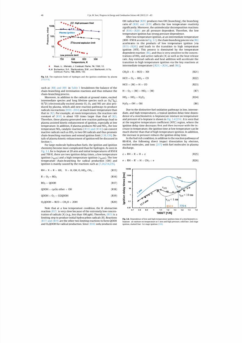
7/21/2019 Plasma Assisted Combustion Dynamics and Chemistry
http://slidepdf.com/reader/full/plasma-assisted-combustion-dynamics-and-chemistry 26/63
such as (R8) and (R9) in Table 3 breakdown the balance of thechain-branching and termination reactions and thus enhance thechain-branching process.
Moreover, in addition to the radicals at ground states, excitedintermediate species and long lifetime species such as O 2(1Dg),O(1D) (electronically excited atomic O), O 3 and NO are also pro-duced by plasma, which add new reaction pathways to produceradicals via reactions (R10) e (R14) at much lower temperature thanthat in (R2). For example, at room temperature, the reaction rateconstant of (R10) is about 100 times larger than that of (R2).Therefore, these plasma generated new reaction pathways lead toplasma assisted kinetic enhancement of ignition, especially at lowtemperature. In addition, if plasma produces NO and NO 2, the lowtemperature NO x catalytic reactions ( (R13) and (R14) ) can convertinactive radicals such as HO 2 to two OH radicals and thus promote
chain-branching reactions and extend ignition limit [138,139] . De-tails of plasma kinetic enhancement of ignition will be discussed inSection 4 .
For large molecule hydrocarbon fuels, the ignition and ignitionchemistry become more complicated than for hydrogen. As seen inFig. 3.1, for n-heptane at 20 atm and initial temperatures of 850 Kand 700 K, there are two ignition delay times, a low temperatureignition ( t ig,LTI) and a high temperature ignition ( t ig,HTI). The lowtemperature chain-branching for radical production (OH) andignition is mainly caused by the reactions such as [7,24,214,215] ,
RH þ X ¼ R þ HX, X ¼ H, OH, O, HO2, CH3… (R15)
R þ O2 ¼ RO2 (R16)
RO2 ¼ QOOH (R17)
QOOH ¼ cyclic ether þ OH (R18)
QOOH þ O2 ¼ O2QOOH (R19)
O2QOOH ¼ RCO þ CH2O þ 2OH (R20)
Note that at a low temperature condition, the H abstractionreaction (R15) is very slow because of the extremely low concen-tration of radicals (X) (e.g., less than 100 ppb). Therefore, (R15) is alimiting step to produce initial hydrocarbon radicals (R). Reactions(R17) and (R19) are the other two limiting reactions to form QOOH
and O 2QOOH for radical production. Since (R18) only produces one
OH radical but (R20) produces two OH (branching), the branchingratio of (R18) and (R19) affects the low temperature reactivitysigni cantly. Moreover, the unimolecular decomposition reactionsof (R16) e (R20) are all pressure dependent. Therefore, the lowtemperature ignition has strong pressure dependence.
After low temperature ignition, at an intermediate temperature(800 e 950 K asseen in Fig. 3.1 ), the chain branching process via (R6)accelerates in the products of low temperature ignition (via(R15) e (R20) ) and leads to the transition to high temperatureignition (HTI). This process is dominated by the temperaturedependent reaction (R6), and thus is very sensitive to the concen-trations of HO 2 and active radicals (X) as well as the heat releaserate. Any external radicals and heat addition will accelerate thetransition to high temperature ignition via the key reactions atintermediate temperature ( (R21) e (R24) , and (R6)),
CH2O þ X ¼ HCO þ XH (R21)
HCO þ O2 ¼ HO2 þ CO (R22)
HCO þ (M) ¼ H þ CO (R23)
H þ O2 þ (M) ¼ HO2 þ (M) (R7)
HO2 þ HO2 ¼ H2O2 (R24)
H2O2 ¼ OH þ OH (R6)
Due to the distinctive fuel oxidation pathways in low, interme-diate, and high temperatures, a typical ignition delay time depen-dence of a stoichiometric n-heptane/air mixture on temperatureand pressure of n-heptane is shown in Fig. 3.4 [216] . It is seen thatat the negative temperature coef cient (NTC) region, where theignition delay time decreases rst and then increase with the in-crease in temperature, the ignition time at low temperature can bemuch shorter than that of high temperature ignition. In addition,
the increase in pressure reduces the ignition delay time.In the fuel rich condition, in addition to the reaction pathways of
R8-R14, the following direct impact dissociation by electron,excited molecules, and ions [217] with fuel molecules in plasmadischarge,
e þ RH ¼ R þ H þ e (R25)
e þ RH ¼ R 0 þ H þ CH3 þ e (R26)
Fig. 3.3. The explosion limits of hydrogen and the ignition conditions by plasma[212,213] .
Fig. 3.4. Dependence of low and high temperature ignition time of a stoichiometry n-heptane e air mixture on temperature at 1 atm and high pressure, solid line: 2nd stage
ignition, dashed line: 1st stage ignition [216] .
Y. Ju, W. Sun / Progress in Energy and Combustion Science 48 (2015) 21 e 8346
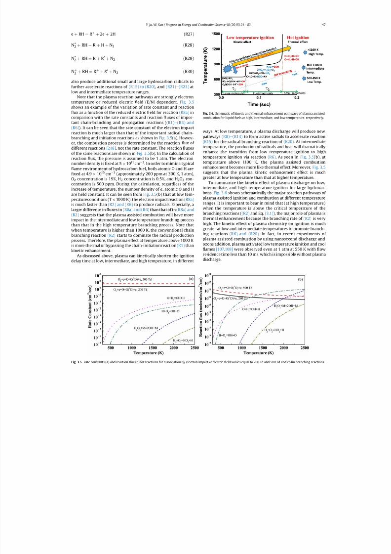
7/21/2019 Plasma Assisted Combustion Dynamics and Chemistry
http://slidepdf.com/reader/full/plasma-assisted-combustion-dynamics-and-chemistry 27/63
e þ RH ¼ R þ þ 2e þ 2H (R27)
N*2 þ RH ¼ R þ H þ N2 (R28)
N*2 þ RH ¼ R þ R 0 þ N2 (R29)
Nþ2 þ RH ¼ R
þþ R
0þ N2 (R30)
also produce additional small and large hydrocarbon radicals tofurther accelerate reactions of (R15) to (R20) , and (R21) e (R23) atlow and intermediate temperature ranges.
Note that the plasma reaction pathways are strongly electrontemperature or reduced electric eld (E/N) dependent. Fig. 3.5shows an example of the variation of rate constant and reaction
ux as a function of the reduced electric eld for reaction (R8a) incomparison with the rate constants and reaction uxes of impor-tant chain-branching and propagation reactions ( (R1) e (R3) and(R6) ). It can be seen that the rate constant of the electron impactreaction is much larger than that of the important radical chain-branching and initiation reactions as shown in Fig. 3.5(a). Howev-er, the combustion process is determined by the reaction ux of different reactions [218] , not the rate constant. The reaction uxesof the same reactions are shown in Fig. 3.5(b). In the calculation of reaction ux, the pressure is assumed to be 1 atm. The electronnumber density is xedat 5 1011 cm 3. In order to mimic a typical
ame environment of hydrocarbon fuel, both atomic O and H arexed at 4.9 1015 cm 3 (approximately 200 ppm at 300 K, 1 atm),
O2 concentration is 19%, H 2 concentration is 0.5%, and H 2O2 con-centration is 500 ppm. During the calculation, regardless of theincrease of temperature, the number density of e, atomic O and Hare held constant. It can be seen from Fig. 3.5(b) that at low tem-peratureconditions (T < 1000 K), the electron impact reaction (R8a)is much faster than (R2) and (R6) to produce radicals. Especially, alarger difference in uxes in (R8a) and (R6) than that of in (R8a) and(R2) suggests that the plasma assisted combustion will have moreimpact in the intermediate and low temperature branching processthan that in the high temperature branching process. Note thatwhen temperature is higher than 1000 K, the conventional chainbranching reaction (R2) starts to dominate the radical productionprocess. Therefore, the plasma effect at temperature above 1000 Kis more thermal or bypassing the chain-initiation reaction (R1) thankinetic enhancement.
As discussed above, plasma can kinetically shorten the ignitiondelay time at low, intermediate, and high temperature, in different
ways. At low temperature, a plasma discharge will produce newpathways (R8) e (R14) to form active radials to accelerate reaction(R15) for the radical branching reaction of (R20) . At intermediatetemperature, the production of radicals and heat will dramaticallyenhance the transition from low temperature ignition to hightemperature ignition via reaction (R6). As seen in Fig. 3.5(b), attemperature above 1100 K, the plasma assisted combustionenhancement becomes more like thermal effect. Moreover, Fig. 3.5suggests that the plasma kinetic enhancement effect is muchgreater at low temperature than that at higher temperature.
To summarize the kinetic effect of plasma discharge on low,intermediate, and high temperature ignition for large hydrocar-bons, Fig. 3.6 shows schematically the major reaction pathways of plasma assisted ignition and combustion at different temperatureranges. It is important to bear in mind that (at high temperature)when the temperature is above the critical temperature of thebranching reactions ( (R2) and Eq. (3.1) ), the major role of plasma is
thermal enhancement because the branching rate of (R2) is veryhigh. The kinetic effect of plasma chemistry on ignition is muchgreater at low and intermediate temperatures to promote branch-ing reactions (R6) and (R20) . In fact, in recent experiments of plasma assisted combustion by using nanosecond discharge andozone addition, plasma activated low temperature ignition and cool
ames [107,108] were observed even at 1 atm at 550 K with owresidence time less than 10 ms, which is impossible without plasmadischarge.
Fig. 3.5. Rate constants (a) and reaction
ux (b) for reactions for dissociation by electron impact at electric
eld values equal to 200 Td and 500 Td and chain branching reactions.
Fig. 3.6. Schematic of kinetic and thermal enhancement pathways of plasma assistedcombustion for liquid fuels at high, intermediate, and low temperature, respectively.
Y. Ju, W. Sun / Progress in Energy and Combustion Science 48 (2015) 21 e 83 47
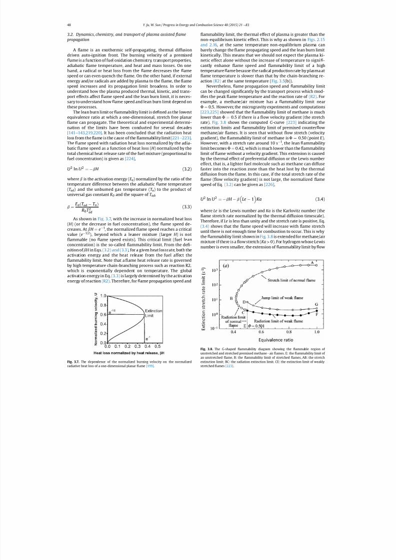
7/21/2019 Plasma Assisted Combustion Dynamics and Chemistry
http://slidepdf.com/reader/full/plasma-assisted-combustion-dynamics-and-chemistry 28/63
3.2. Dynamics, chemistry, and transport of plasma assisted ame propagation
A ame is an exothermic self-propagating, thermal diffusiondriven auto-ignition front. The burning velocity of a premixed
ame is a function of fuel oxidation chemistry, transport properties,adiabatic ame temperature, and heat and mass losses. On onehand, a radical or heat loss from the ame decreases the amespeed or can even quench the ame. On the other hand, if externalenergy and/or radicals are added by plasma to the ame, the amespeed increases and its propagation limit broadens. In order tounderstand how the plasma produced thermal, kinetic, and trans-port effects affect ame speed and the lean burn limit, it is neces-sary to understand how ame speed and lean burn limit depend onthese processes.
The lean burn limit or ammability limit is de ned as the lowestequivalence ratio at which a one-dimensional, stretch free planar
ame can propagate. The theoretical and experimental determi-nation of the limits have been conducted for several decades[141 e 143,219,220] . It has been concluded that the radiation heatloss from the ame is the cause of the ammability limit [221 e 223] .The ame speed with radiation heat loss normalized by the adia-batic ame speed as a function of heat loss ( H ) normalized by thetotal chemical heat release rate of the fuel mixture (proportional tofuel concentration) is given as [224] ,
U 2 ln U 2 ¼ b H (3.2)
where b is the activation energy ( E a) normalized by the ratio of thetemperature difference between the adiabatic ame temperature(T ad ) and the unburned gas temperature ( T u) to the product of universal gas constant R0 and the square of T ad ,
b ¼ E a ðT ad T u Þ
R0 T 2ad(3.3)
As shown in Fig. 3.7, with the increase in normalized heat loss(H ) (or the decrease in fuel concentration), the ame speed de-creases. At bH ¼ e 1, the normalized ame speed reaches a criticalvalue ( e 1/2 ), beyond which a leaner mixture (larger H ) is not
ammable (no ame speed exists). This critical limit (fuel leanconcentration) is the so-called ammability limit. From the de -nition of bH in Eqs. (3.2) and (3.3) , for a given heat lossrate, both theactivation energy and the heat release from the fuel affect the
ammability limit. Note that a ame heat release rate is governedby high temperature chain-branching process such as reaction R2,which is exponentially dependent on temperature. The globalactivation energy in Eq. (3.3) is largely determined by the activationenergy of reaction (R2). Therefore, for ame propagation speed and
ammability limit, the thermal effect of plasma is greater than thenon-equilibrium kinetic effect. This is why as shown in Figs. 2.15and 2.16 , at the same temperature non-equilibrium plasma canbarely change the ame propagating speed and the lean burn limitkinetically. This means that we should not expect the plasma ki-netic effect alone without the increase of temperature to signi -cantly enhance ame speed and ammability limit of a hightemperature ame because the radical production rate by plasma at
ame temperature is slower than that by the chain-branching re-action (R2) at the same temperature ( Fig. 3.5 (b)).
Nevertheless, ame propagation speed and ammability limitcan be changed signi cantly by the transport process which mod-i es the peak ame temperature and the reaction rate of (R2). Forexample, a methane/air mixture has a ammability limit nearF ¼ 0.5. However, the microgravity experiments and computations[223,225] showed that the ammability limit of methane is muchlower than F ¼ 0.5 if there is a ow velocity gradient (the stretchrate). Fig. 3.8 shows the computed G-curve [223] indicating theextinction limits and ammability limit of premixed counter owmethane/air ames. It is seen that without ow stretch (velocitygradient), the ammability limit of methane is F ¼ 0.50 (point E ).However, with a stretch rate around 10 s 1, the lean ammabilitylimit becomes F ¼ 0.42, which is much lower than the ammabilitylimit of ame without a velocity gradient. This extension is causedby the thermal effect of preferential diffusion or the Lewis numbereffect, that is, a lighter fuel molecule such as methane can diffusefaster into the reaction zone than the heat lost by the thermaldiffusion from the ame. In this case, if the total stretch rate of the
ame ( ow velocity gradient) is not large, the normalized amespeed of Eq. (3.2) can be given as [226] ,
U 2 ln U 2 ¼ b H b Le 1 Ka (3.4)
where Le is the Lewis number and Ka is the Karlovitz number (theame stretch rate normalized by the thermal diffusion timescale).
Therefore, if Le is less than unity and the stretch rate is positive, Eq.(3.4) shows that the ame speed will increase with ame stretchuntil there is not enough time for combustion to occur. This is whythe ammability limit shown in Fig. 3.8 is extendedfor methane/airmixture if there is a ow stretch ( Ka > 0). For hydrogen whose Lewisnumber is even smaller, the extension of ammability limit by ow
Fig. 3.7. The dependence of the normalized burning velocity on the normalized
radiative heat loss of a one-dimensional planar
ame [199] .
Fig. 3.8. The G-shaped ammability diagram showing the ammable region of unstretched and stretched premixed methane e air ames. E: the ammability limit of an unstretched ame, B: the ammability limit of stretched ames, AB: the stretchextinction limit; BC: the radiation extinction limit. CE: the extinction limit of weakly
stretched
ames [223] .
Y. Ju, W. Sun / Progress in Energy and Combustion Science 48 (2015) 21 e 8348
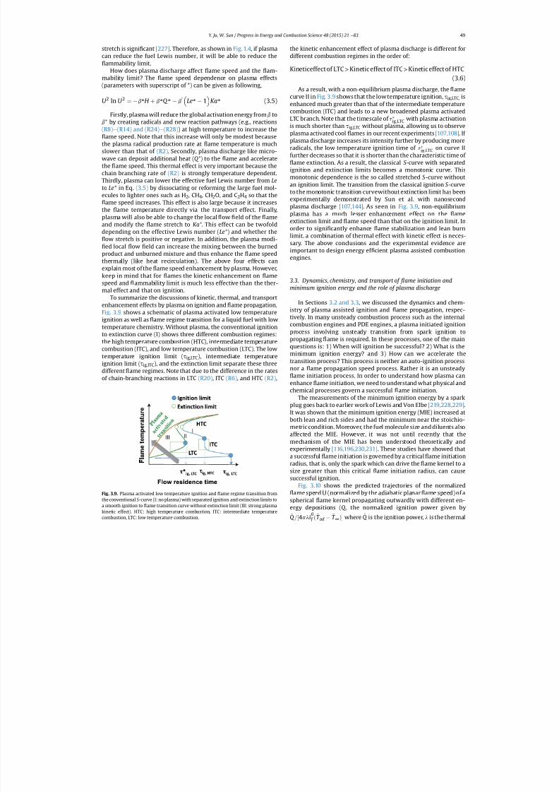
7/21/2019 Plasma Assisted Combustion Dynamics and Chemistry
http://slidepdf.com/reader/full/plasma-assisted-combustion-dynamics-and-chemistry 29/63
stretch is signi cant [227] . Therefore, as shown in Fig. 1.4 , if plasmacan reduce the fuel Lewis number, it will be able to reduce the
ammability limit.How does plasma discharge affect ame speed and the am-
mability limit? The ame speed dependence on plasma effects(parameters with superscript of *) can be given as following,
U 2
ln U 2
¼ b*
H þ b*
Q *
b
0
Le*
1 Ka*
(3.5)Firstly, plasma will reduce the global activation energy from b to
b* by creating radicals and new reaction pathways (e.g., reactions(R8) e (R14) and (R24) e (R28) ) at high temperature to increase the
ame speed. Note that this increase will only be modest becausethe plasma radical production rate at ame temperature is muchslower than that of (R2). Secondly, plasma discharge like micro-wave can deposit additional heat ( Q*) to the ame and acceleratethe ame speed. This thermal effect is very important because thechain branching rate of (R2) is strongly temperature dependent.Thirdly, plasma can lower the effective fuel Lewis number from Leto Le* in Eq. (3.5) by dissociating or reforming the large fuel mol-ecules to lighter ones such as H 2, CH4, CH2O, and C 2H4 so that the
ame speed increases. This effect is also large because it increasesthe ame temperature directly via the transport effect. Finally,plasma will also be able to change the local ow eld of the ameand modify the ame stretch to Ka*. This effect can be twofolddepending on the effective Lewis number ( Le*) and whether the
ow stretch is positive or negative. In addition, the plasma modi-ed local ow eld can increase the mixing between the burned
product and unburned mixture and thus enhance the ame speedthermally (like heat recirculation). The above four effects canexplain most of the ame speed enhancement by plasma. However,keep in mind that for ames the kinetic enhancement on amespeed and ammability limit is much less effective than the ther-mal effect and that on ignition.
To summarize the discussions of kinetic, thermal, and transportenhancement effects by plasma on ignition and ame propagation,
Fig. 3.9 shows a schematic of plasma activated low temperatureignition as well as ame regime transition for a liquid fuel with lowtemperature chemistry. Without plasma, the conventional ignitionto extinction curve (I) shows three different combustion regimes:the high temperature combustion (HTC), intermediate temperaturecombustion (ITC), and low temperature combustion (LTC). The lowtemperature ignition limit ( t ig,LTC), intermediate temperatureignition limit ( t ig,ITC), and the extinction limit separate these threedifferent ame regimes. Note that due to the difference in the ratesof chain-branching reactions in LTC (R20) , ITC (R6), and HTC (R2),
the kinetic enhancement effect of plasma discharge is different fordifferent combustion regimes in the order of:
Kineticeffectof LTC > Kineticeffect of ITC > Kineticeffect of HTC(3.6)
As a result, with a non-equilibrium plasma discharge, the amecurve II in Fig. 3.9 shows that the low temperature ignition, t ig,LTC, is
enhanced much greater than that of the intermediate temperaturecombustion (ITC) and leads to a new broadened plasma activatedLTC branch. Note that the timescale of t ig;LTC with plasma activationis much shorter than t ig,LTC without plasma, allowing us to observeplasma activated cool ames in our recent experiments [107,108] . If plasma discharge increases its intensity further by producing moreradicals, the low temperature ignition time of t ig;LTC on curve IIfurther decreases so that it is shorter than the characteristic time of
ame extinction. As a result, the classical S -curve with separatedignition and extinction limits becomes a monotonic curve. Thismonotonic dependence is the so called stretched S -curve withoutan ignition limit. The transition from the classical ignition S -curveto the monotonic transition curvewithout extinction limit has beenexperimentally demonstrated by Sun et al. with nanosecond
plasma discharge [107,144] . As seen in Fig. 3.9, non-equilibriumplasma has a much lesser enhancement effect on the ameextinction limit and ame speed than that on the ignition limit. Inorder to signi cantly enhance ame stabilization and lean burnlimit, a combination of thermal effect with kinetic effect is neces-sary. The above conclusions and the experimental evidence areimportant to design energy ef cient plasma assisted combustionengines.
3.3. Dynamics, chemistry, and transport of ame initiation andminimum ignition energy and the role of plasma discharge
In Sections 3.2 and 3.3 , we discussed the dynamics and chem-
istry of plasma assisted ignition and
ame propagation, respec-tively. In many unsteady combustion process such as the internalcombustion engines and PDE engines, a plasma initiated ignitionprocess involving unsteady transition from spark ignition topropagating ame is required. In these processes, one of the mainquestions is: 1) When will ignition be successful? 2) What is theminimum ignition energy? and 3) How can we accelerate thetransition process? This process is neither an auto-ignition processnor a ame propagation speed process. Rather it is an unsteady
ame initiation process. In order to understand how plasma canenhance ame initiation, we need to understand what physical andchemical processes govern a successful ame initiation.
The measurements of the minimum ignition energy by a sparkplug goes back to earlier work of Lewis and Von Elbe [219,228,229] .It was shown that the minimum ignition energy (MIE) increased atboth lean and rich sides and had the minimum near the stoichio-metric condition. Moreover, the fuel molecule size and diluents alsoaffected the MIE. However, it was not until recently that themechanism of the MIE has been understood theoretically andexperimentally [116,196,230,231] . These studies have showed thata successful ame initiation is governed by a critical ame initiationradius, that is, only the spark which can drive the ame kernel to asize greater than this critical ame initiation radius, can causesuccessful ignition.
Fig. 3.10 shows the predicted trajectories of the normalizedame speed U (normalized by the adiabatic planar ame speed) of a
spherical ame kernel propagating outwardly with different en-ergy depositions ( Q , the normalized ignition power given by
~
Q =½4p
~
l
~
d
0
f ð
~
T ad
~
T ∞ Þ where
~
Q is the ignition power,
~
l is the thermal
Fig. 3.9. Plasma activated low temperature ignition and ame regime transition fromthe conventional S -curve (I: no plasma) with separated ignition and extinction limits toa smooth ignition to ame transition curve without extinction limit (III: strong plasmakinetic effect). HTC: high temperature combustion, ITC: intermediate temperature
combustion, LTC: low temperature combustion.
Y. Ju, W. Sun / Progress in Energy and Combustion Science 48 (2015) 21 e 83 49
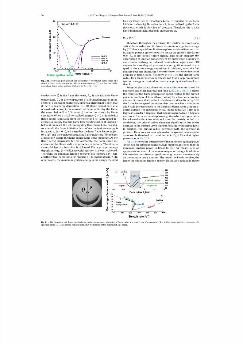
7/21/2019 Plasma Assisted Combustion Dynamics and Chemistry
http://slidepdf.com/reader/full/plasma-assisted-combustion-dynamics-and-chemistry 30/63
conductivity, ~
d0 f is the ame thickness,
~
T ad is the adiabatic ame
temperature, ~
T ∞ is the temperature of unburned mixture) in thecenter of a quiescent mixture of a spherical chamber. It is seen thatif there is no energy deposition ( Q ¼ 0), ame cannot exist at anormalized radius (R, the normalized ame radius by the amethickness) below R ¼ 2.5 (point c ) due to the stretch by amecurvature. When a small normalized energy ( Q ¼ 0.1) is added, a
ame kernel is initiated from the center and its ame speed de-creases so quickly that the ame kernel extinguishes at location f before it can reach the self-propagating ame branch starting at d.As a result, the ame initiation fails. When the ignition energy isincreased to Q ¼ 0.15, it is seen that the inner ame kernel trajec-
tory ( gh) and the outside propagating ame trajectory ( hb ) mergesat location h where the ame kernel ame is the minimum. As theame kernel propagates further outwardly, the ame speed in-
creases as the ame radius approaches to in nity. Therefore, asuccessful ignition initiation is achieved. For any larger energydeposition (e.g., Q ¼ 0.6), successful ignition is always achieved.Therefore, the minimum ignition energy of this mixture is Q ¼ 0.15and the critical ame initiation radiusis R ¼ R c (radius at point h).Inother words, the minimum ignition energy is the energy required
for a spark todrive the initial ame kernel to reach the critical ameinitiation radius (Rc ). Note that here Rc is normalized by the amethickness, which is function of pressure. Therefore, the critical
ame initiation radius depends on pressure as,
Rc P n=2 (3.7)
Therefore, the higher the pressure, the smaller the dimensionalcritical ame radius and the lower the minimum ignition energy.Eq. (3.7) has a special implication to plasma assisted ignition, thatis, a good plasma igniter needs to create an ignition size largerthan Rc , to not deposit more energy. This result supports theobservation of ignition enhancement by microwave, gliding arc,and corona discharge in internal combustion engines and PDEengines because they all produce a larger ignition kernel than aspark at the same energy deposition. In addition, when the fuelmixture becomes leaner, the ame thickness increases due to thedecrease in ame speed. As shown in Fig. 3.10 , the critical ameradius for a leaner mixture increases and thus a larger minimumignition energy is required to create a larger ignition kernel sizethan Rc .
Recently, the critical ame initiation radius was measured forhydrogen and other hydrocarbon fuels [230,231] . Fig. 3.11 showsthe results of the ame propagation speed relative to the burnedgas as a function of time ( ame radius) for a lean n-decane/airmixture. It is seen that similar to the theoretical results in Fig. 3.10 ,the ame kernel speed decreases rst then reaches a minimum,and nally increases back to the adiabatic ame speed as it prop-agates outside. The measured critical ame radius at 1 atm is aslarge as 1.4 cm for n-heptane. That means to ignite a lean n-heptanemixture at 1 atm we need a plasma igniter which can generate a
ame kernel with radius as big as 1.4 cm. Fortunately, at fuel richconditions, the critical radius decreases signi cantly due to thedecrease in the mixture Lewis number for large hydrocarbon fuels.In addition, the critical radius decreases with the increase inpressure. These conclusions explain why the ignition enhancement
decreases both in fuel rich condition as in Fig. 2.15 and at higherpressure as in Fig. 2.16 .
Fig. 3.12 shows the dependence of the minimum ignition power(Q ) on Rc3 for different mixture Lewis numbers. It is seen that theminimum ignition power is linear to Rc
3. That means Rc is anappropriate measure of the minimum ignition energy. In addition,it is seen that the minimum ignition energy depends monotonicallyon the mixture Lewis number. The larger the Lewis number, thelarger the minimum ignition energy. This is why ignition is always
Fig. 3.10. Theoretical prediction of the trajectories of normalized ame speed of aspherical ame kernel initiated by different external energy ( Q ) as a function of thenormalized ame radius by ame thickness for Le ¼ 1.2 [116] .
Fig. 3.11. The dependence of ame speed relative to the burned gas as a function of ame radius and stretch rate of n-decane/air ( F ¼ 0.7) at 1 atm ignited at the center of a
spherical bomb [231] . The critical radius is de ned at the location of the minimum
ame speed.
Y. Ju, W. Sun / Progress in Energy and Combustion Science 48 (2015) 21 e 8350
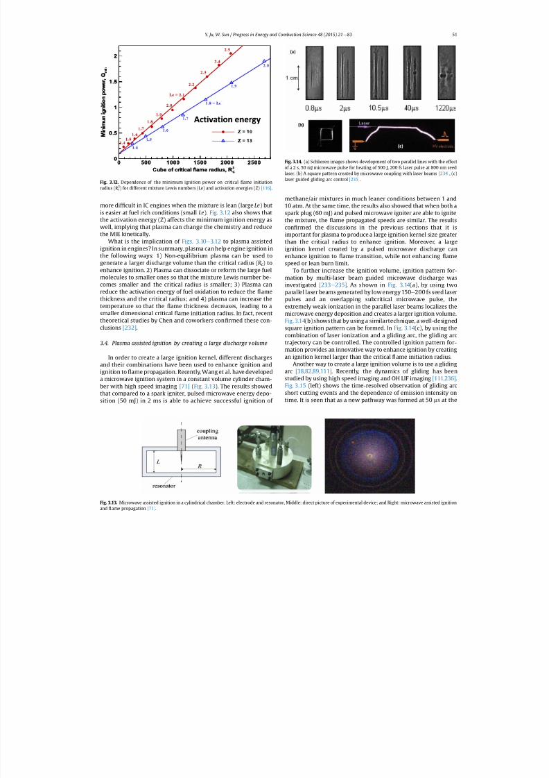
7/21/2019 Plasma Assisted Combustion Dynamics and Chemistry
http://slidepdf.com/reader/full/plasma-assisted-combustion-dynamics-and-chemistry 31/63
more dif cult in IC engines when the mixture is lean (large Le) butis easier at fuel rich conditions (small Le). Fig. 3.12 also shows thatthe activation energy (Z) affects the minimum ignition energy aswell, implying that plasma can change the chemistry and reducethe MIE kinetically.
What is the implication of Figs. 3.10 e 3.12 to plasma assistedignition in engines? In summary, plasma can help engine ignition inthe following ways: 1) Non-equilibrium plasma can be used togenerate a larger discharge volume than the critical radius ( Rc ) toenhance ignition. 2) Plasma can dissociate or reform the large fuelmolecules to smaller ones so that the mixture Lewis number be-comes smaller and the critical radius is smaller; 3) Plasma canreduce the activation energy of fuel oxidation to reduce the amethickness and the critical radius; and 4) plasma can increase the
temperature so that the ame thickness decreases, leading to asmaller dimensional critical ame initiation radius. In fact, recenttheoretical studies by Chen and coworkers con rmed these con-clusions [232] .
3.4. Plasma assisted ignition by creating a large discharge volume
In order to create a large ignition kernel, different dischargesand their combinations have been used to enhance ignition andignition to ame propagation. Recently, Wang et al. have developeda microwave ignition system in a constant volume cylinder cham-ber with high speed imaging [71] (Fig. 3.13 ). The results showedthat compared to a spark igniter, pulsed microwave energy depo-sition (50 mJ) in 2 ms is able to achieve successful ignition of
methane/air mixtures in much leaner conditions between 1 and10 atm. At the same time, the results also showed that when both aspark plug (60 mJ) and pulsed microwave igniter are able to ignitethe mixture, the ame propagated speeds are similar. The resultscon rmed the discussions in the previous sections that it isimportant for plasma to produce a large ignition kernel size greaterthan the critical radius to enhance ignition. Moreover, a largeignition kernel created by a pulsed microwave discharge canenhance ignition to ame transition, while not enhancing amespeed or lean burn limit.
To further increase the ignition volume, ignition pattern for-mation by multi-laser beam guided microwave discharge wasinvestigated [233 e 235] . As shown in Fig. 3.14 (a), by using twoparallel laser beams generated by low energy 150 e 200 fs seed laserpulses and an overlapping subcritical microwave pulse, the
extremely weak ionization in the parallel laser beams localizes themicrowave energy deposition and creates a larger ignition volume.Fig. 3.14 (b) shows that by using a similartechnique, a well-designedsquare ignition pattern can be formed. In Fig. 3.14 (c), by using thecombination of laser ionization and a gliding arc, the gliding arctrajectory can be controlled. The controlled ignition pattern for-mation provides an innovative way to enhance ignition by creatingan ignition kernel larger than the critical ame initiation radius.
Another way to create a large ignition volume is to use a glidingarc [38,82,89,111] . Recently, the dynamics of gliding has beenstudied by using high speed imaging and OH LIF imaging [111,236] .Fig. 3.15 (left) shows the time-resolved observation of gliding arcshort cutting events and the dependence of emission intensity ontime. It is seen that as a new pathway was formed at 50 ms at the
Fig. 3.12. Dependence of the minimum ignition power on critical ame initiationradius (R c
3) for different mixture Lewis numbers (Le) and activation energies (Z) [116] .
Fig. 3.13. Microwave assisted ignition in a cylindrical chamber. Left: electrode and resonator, Middle: direct picture of experimental device; and Right: microwave assisted ignition
and
ame propagation [71] .
Fig. 3.14. (a) Schlieren images shows development of two parallel lines with the effectof a 2 s, 50 mJ microwave pulse for heating of 500 J, 200 fs laser pulse at 800 nm seedlaser. (b) A square pattern created by microwave coupling with laser beams [234] , (c)laser guided gliding arc control [235] .
Y. Ju, W. Sun / Progress in Energy and Combustion Science 48 (2015) 21 e 83 51
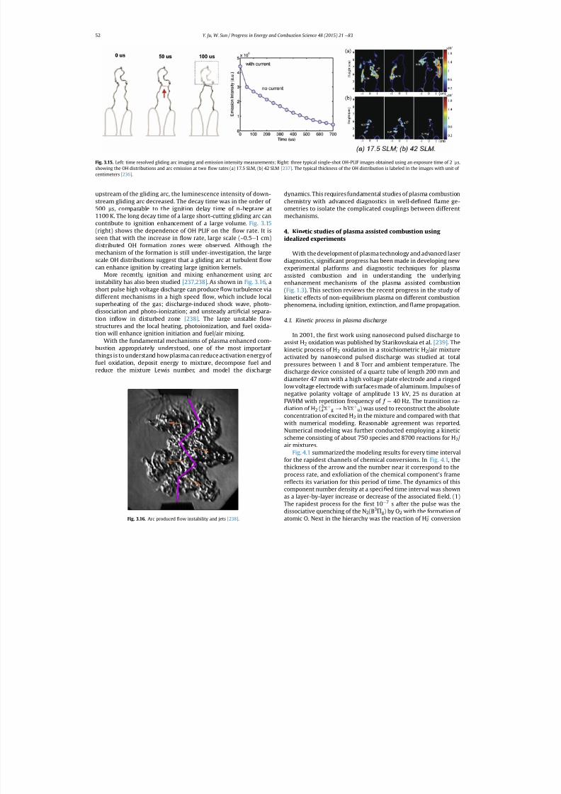
7/21/2019 Plasma Assisted Combustion Dynamics and Chemistry
http://slidepdf.com/reader/full/plasma-assisted-combustion-dynamics-and-chemistry 32/63
upstream of the gliding arc, the luminescence intensity of down-stream gliding arc decreased. The decay time was in the order of
500 ms, comparable to the ignition delay time of n-heptane at1100 K. The long decay time of a large short-cutting gliding arc cancontribute to ignition enhancement of a large volume. Fig. 3.15(right) shows the dependence of OH PLIF on the ow rate. It isseen that with the increase in ow rate, large scale (~0.5 e 1 cm)distributed OH formation zones were observed. Although themechanism of the formation is still under-investigation, the largescale OH distributions suggest that a gliding arc at turbulent owcan enhance ignition by creating large ignition kernels.
More recently, ignition and mixing enhancement using arcinstability has also been studied [237,238] . As shown in Fig. 3.16 , ashort pulse high voltage discharge can produce ow turbulence viadifferent mechanisms in a high speed ow, which include localsuperheating of the gas; discharge-induced shock wave, photo-
dissociation and photo-ionization; and unsteady arti cial separa-tion in ow in disturbed zone [238] . The large unstable owstructures and the local heating, photoionization, and fuel oxida-tion will enhance ignition initiation and fuel/air mixing.
With the fundamental mechanisms of plasma enhanced com-bustion appropriately understood, one of the most importantthings is to understand how plasma can reduce activation energy of fuel oxidation, deposit energy to mixture, decompose fuel andreduce the mixture Lewis number, and model the discharge
dynamics. This requires fundamental studies of plasma combustionchemistry with advanced diagnostics in well-de ned ame ge-
ometries to isolate the complicated couplings between differentmechanisms.
4. Kinetic studies of plasma assisted combustion using idealized experiments
With the development of plasma technology and advanced laserdiagnostics, signi cant progress has been made in developing newexperimental platforms and diagnostic techniques for plasmaassisted combustion and in understanding the underlyingenhancement mechanisms of the plasma assisted combustion(Fig. 1.3 ). This section reviews the recent progress in the study of kinetic effects of non-equilibrium plasma on different combustionphenomena, including ignition, extinction, and ame propagation.
4.1. Kinetic process in plasma discharge
In 2001, the rst work using nanosecond pulsed discharge toassist H 2 oxidation was published by Starikovskaia et al. [239] . Thekinetic process of H 2 oxidation in a stoichiometric H 2/air mixtureactivated by nanosecond pulsed discharge was studied at totalpressures between 1 and 8 Torr and ambient temperature. Thedischarge device consisted of a quartz tube of length 200 mm anddiameter 47 mm with a high voltage plate electrode and a ringedlow voltage electrode with surfaces made of aluminum. Impulses of negative polarity voltage of amplitude 13 kV, 25 ns duration atFWHM with repetition frequency of f ¼ 40 Hz. The transition ra-diation of H 2 (a
3S þg / b3 S þ
u) was used to reconstruct the absolute
concentration of excited H 2 in the mixture and compared with thatwith numerical modeling. Reasonable agreement was reported.Numerical modeling was further conducted employing a kineticscheme consisting of about 750 species and 8700 reactions for H 2/air mixtures.
Fig. 4.1 summarized the modeling results for every time intervalfor the rapidest channels of chemical conversions. In Fig. 4.1, thethickness of the arrow and the number near it correspond to theprocess rate, and exfoliation of the chemical component's framere ects its variation for this period of time. The dynamics of thiscomponent number density at a speci ed time interval was shownas a layer-by-layer increase or decrease of the associated eld. (1)The rapidest process for the rst 10 7 s after the pulse was thedissociative quenching of the N 2(B3P g) by O 2 with the formation of
atomic O. Next in the hierarchy was the reaction of H 2þ
conversion
Fig. 3.15. Left: time resolved gliding arc imaging and emission intensity measurements; Right: three typical single-shot OH-PLIF images obtained using an exposure time of 2 ms,showing the OH distributions and arc emission at two ow rates (a) 17.5 SLM, (b) 42 SLM [237] . The typical thickness of the OH distribution is labeled in the images with unit of centimeters [236] .
Fig. 3.16. Arc produced
ow instability and jets [238] .
Y. Ju, W. Sun / Progress in Energy and Combustion Science 48 (2015) 21 e 8352
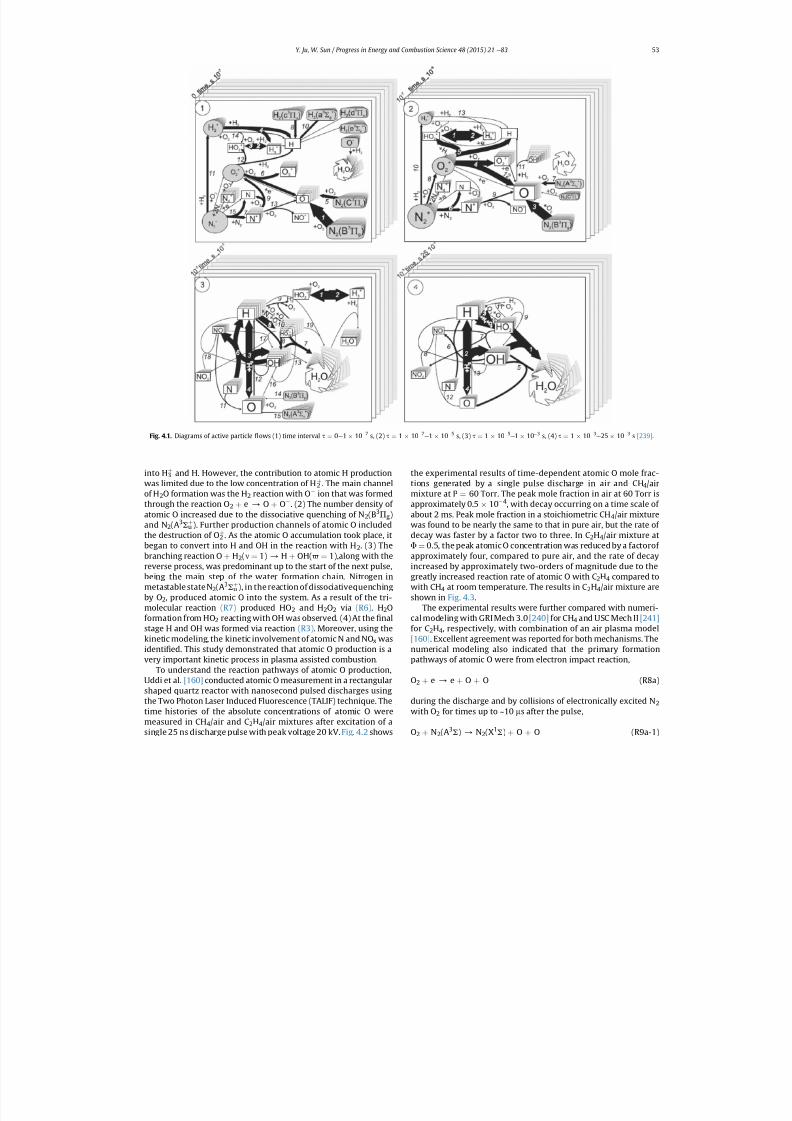
7/21/2019 Plasma Assisted Combustion Dynamics and Chemistry
http://slidepdf.com/reader/full/plasma-assisted-combustion-dynamics-and-chemistry 33/63
into H 3þ and H. However, the contribution to atomic H production
was limited due to the low concentration of H 2þ . The main channel
of H 2O formation was the H 2 reaction with O ion that was formedthrough the reaction O 2 þ e / O þ O . (2) The number density of atomic O increased due to the dissociative quenching of N 2(B3P g)and N 2(A3S u
þ ). Further production channels of atomic O includedthe destruction of O 2
þ . As the atomic O accumulation took place, itbegan to convert into H and OH in the reaction with H 2. (3) Thebranching reaction O þ H2(n ¼ 1) / H þ OH(6 ¼ 1),along with thereverse process, was predominant up to the start of the next pulse,being the main step of the water formation chain. Nitrogen in
metastable stateN 2(A3
S uþ
), in the reaction of dissociativequenchingby O2, produced atomic O into the system. As a result of the tri-molecular reaction (R7) produced HO 2 and H 2O2 via (R6). H2Oformation from HO 2 reacting with OH was observed. (4) At the nalstage H and OH was formed via reaction (R3). Moreover, using thekinetic modeling, the kinetic involvement of atomic N and NO x wasidenti ed. This study demonstrated that atomic O production is avery important kinetic process in plasma assisted combustion.
To understand the reaction pathways of atomic O production,Uddi et al. [160] conducted atomic O measurement in a rectangularshaped quartz reactor with nanosecond pulsed discharges usingthe Two Photon Laser Induced Fluorescence (TALIF) technique. Thetime histories of the absolute concentrations of atomic O weremeasured in CH 4/air and C 2H4/air mixtures after excitation of a
single 25 ns discharge pulse with peak voltage 20 kV. Fig. 4.2 shows
the experimental results of time-dependent atomic O mole frac-tions generated by a single pulse discharge in air and CH 4/airmixture at P ¼ 60 Torr. The peak mole fraction in air at 60 Torr isapproximately 0.5 10 4, with decay occurring on a time scale of about 2 ms. Peak mole fraction in a stoichiometric CH 4/air mixturewas found to be nearly the same to that in pure air, but the rate of decay was faster by a factor two to three. In C 2H4/air mixture atF ¼ 0.5, the peak atomic O concentration was reduced by a factorof approximately four, compared to pure air, and the rate of decayincreased by approximately two-orders of magnitude due to thegreatly increased reaction rate of atomic O with C 2H4 compared to
with CH 4 at room temperature. The results in C 2H4/air mixture areshown in Fig. 4.3.
The experimental results were further compared with numeri-cal modeling with GRI Mech 3.0 [240] for CH 4 and USC Mech II [241]for C2H4, respectively, with combination of an air plasma model[160] . Excellent agreement was reported for both mechanisms. Thenumerical modeling also indicated that the primary formationpathways of atomic O were from electron impact reaction,
O2 þ e / e þ O þ O (R8a)
during the discharge and by collisions of electronically excited N 2with O 2 for times up to ~10 ms after the pulse,
O2 þ N2(A3S
)/
N2(X1S
) þ O þ O (R9a-1)
Fig. 4.1. Diagrams of active particle ows (1) time interval t ¼ 0e 1 10 7 s, (2) t ¼ 1 10 7e 1 10 5 s, (3) t ¼ 1 10 5e 1 10 3 s, (4) t ¼ 1 10 3e 25 10 3 s [239] .
Y. Ju, W. Sun / Progress in Energy and Combustion Science 48 (2015) 21 e 83 53
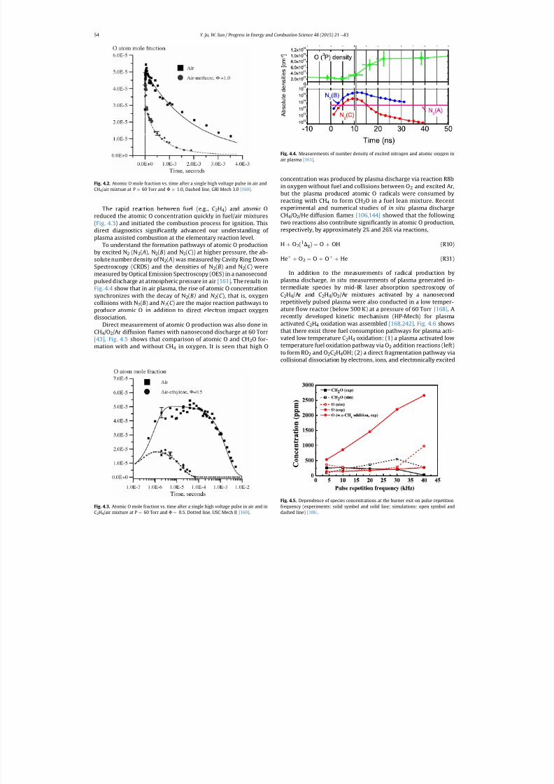
7/21/2019 Plasma Assisted Combustion Dynamics and Chemistry
http://slidepdf.com/reader/full/plasma-assisted-combustion-dynamics-and-chemistry 34/63
The rapid reaction between fuel (e.g., C 2H4) and atomic Oreduced the atomic O concentration quickly in fuel/air mixtures(Fig. 4.3 ) and initiated the combustion process for ignition. Thisdirect diagnostics signi cantly advanced our understanding of plasma assisted combustion at the elementary reaction level.
To understand the formation pathways of atomic O productionby excited N 2 (N2( A), N2(B) and N 2(C )) at higher pressure, the ab-solute number density of N 2( A) was measured by Cavity Ring DownSpectroscopy (CRDS) and the densities of N 2(B) and N 2(C ) weremeasured by Optical Emission Spectroscopy (OES) in a nanosecondpulsed discharge at atmospheric pressure in air [161] . The results inFig. 4.4 show that in air plasma, the rise of atomic O concentrationsynchronizes with the decay of N 2(B) and N 2(C ), that is, oxygencollisions with N 2(B) and N 2(C ) are the major reaction pathways toproduce atomic O in addition to direct electron impact oxygendissociation.
Direct measurement of atomic O production was also done inCH4/O2/Ar diffusion ames with nanosecond discharge at 60 Torr[43] . Fig. 4.5 shows that comparison of atomic O and CH 2O for-mation with and without CH 4 in oxygen. It is seen that high O
concentration was produced by plasma discharge via reaction R8bin oxygen without fuel and collisions between O 2 and excited Ar,but the plasma produced atomic O radicals were consumed byreacting with CH 4 to form CH 2O in a fuel lean mixture. Recentexperimental and numerical studies of in situ plasma dischargeCH4/O2/He diffusion ames [106,144] showed that the followingtwo reactions also contribute signi cantly in atomic O production,respectively, by approximately 2% and 26% via reactions,
H þ O2(1Dg) ¼ O þ OH (R10)
He þ þ O2 ¼ O þ Oþ þ He (R31)
In addition to the measurements of radical production byplasma discharge, in situ measurements of plasma generated in-termediate species by mid-IR laser absorption spectroscopy of C2H4/Ar and C 2H4/O2/Ar mixtures activated by a nanosecondrepetitively pulsed plasma were also conducted in a low temper-
ature ow reactor (below 500 K) at a pressure of 60 Torr [168] . Arecently developed kinetic mechanism (HP-Mech) for plasmaactivated C 2H4 oxidation was assembled [168,242] . Fig. 4.6 showsthat there exist three fuel consumption pathways for plasma acti-vated low temperature C 2H4 oxidation: (1) a plasma activated lowtemperature fuel oxidation pathway via O 2 addition reactions (left)to form RO 2 and O 2C2H4OH; (2) a direct fragmentation pathway viacollisional dissociation by electrons, ions, and electronically excited
Fig. 4.4. Measurements of number density of excited nitrogen and atomic oxygen inair plasma [161] .
Fig. 4.5. Dependence of species concentrations at the burner exit on pulse repetitionfrequency (experiments: solid symbol and solid line; simulations: open symbol and
dashed line) [106] .
Fig. 4.3. Atomic O mole fraction vs. time after a single high voltage pulse in air and in
C2H4/air mixture at P ¼
60 Torr and F ¼
0.5. Dotted line, USC Mech II [160] .
Fig. 4.2. Atomic O mole fraction vs. time after a single high voltage pulse in air andCH4/air mixture at P ¼ 60 Torr and F ¼ 1.0, Dashed line, GRI Mech 3.0 [160] .
Y. Ju, W. Sun / Progress in Energy and Combustion Science 48 (2015) 21 e 8354
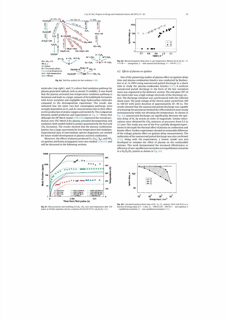
7/21/2019 Plasma Assisted Combustion Dynamics and Chemistry
http://slidepdf.com/reader/full/plasma-assisted-combustion-dynamics-and-chemistry 35/63
molecules (top right); and (3) a direct fuel oxidation pathway byplasma generated radicals such as atomic O (middle). It was foundthat the plasma activated low temperature oxidation pathway isdominant and leads to a larger amount of formaldehyde formationwith lesser acetylene and negligible large hydrocarbon moleculescompared to the decomposition experiment. The results alsoindicated that the latter two fuel consumption pathways werestrongly dependent on O 2 and Ar concentrations due to their effecton the production of atomic oxygen and excited Ar. The comparisonbetween model prediction and experiments in Fig. 4.7 shows thatalthough the HP-Mech model [168,242] improved the overall pre-diction over USC-Mech II for plasma activated decomposition andoxidation, both models failed to predict quantitatively the H 2O andCH4 formation. The results showed that the plasma combustionkinetics has a large uncertainty for low temperature fuel oxidation.Experimental data of intermediate species diagnostics are neededfor future model development in plasma-assisted combustion.
Moreover, the effects of plasma produced O 3 , O2(a1Dg), and NO x
on ignition and ame propagation were also studied [156,157] andwill be discussed in the following sections.
4.2. Effects of plasma on ignition
One of the pioneering studies of plasma effect on ignition delaytime and plasma-combustion kinetics was conducted by Bozhen-
kov et al., in 2003 using nanosecond pulsed discharge in a shocktube to study the plasma-combustion kinetics [213] . A uniformnanosecond pulsed discharge in the form of the fast ionizationwave was organized in the dielectric section. The end plate (EP) of the shock tube was a high voltage electrode of the discharge sys-tem. The discharge initiation was synchronized with the re ectedshock wave. The peak voltage of the electric pulse varied from 100to 160 kV with pulse duration of approximately 30 e 40 ns. Theresults showed that the nanosecond pulsed discharge was capableof activating the premixture behind the re ectedshock wave nearlyinstantaneously while not elevating the temperature. As shown inFig. 4.8 , nanosecond discharge can signi cantly decrease the igni-tion delay of H 2 by nearly an order of magnitude. Similar obser-vations were obtained for CH 4 mixtures at pressures from 0.3 to2.3 atm. This study was one of the rst carefully designed experi-ments to decouple the thermal effect of plasma on combustion andkinetic effect. Further experiments showed no noticeable differenceof the voltage polarity effect on ignition delay measurements. Theuniformity of the nanosecond pulsed discharge was also con rmed[112] . Along with the experiments, a kinetic model was alsodeveloped to simulate the effect of plasma on the combustiblemixture. This work demonstrated the increased effectiveness oref ciency of non-equilibrium excitation overequilibrium excitationin a H 2/O2/N2 system as shown in Fig. 4.9.
Fig. 4.8. Measured ignition delay time vs. gas temperature. Mixture H 2:O2 :N2:Ar ¼ 6:3:11:80. 1 e autoignition, 2 e with nanosecond discharge. U ¼ 160 kV [213] .
Fig. 4.6. Path ux analysis for fuel oxidation [168] .
Fig. 4.7. Measurements and modeling of C 2H2, CH4, H2O, and temperature after 150
pulses at 30 kHz repetition rate for a mixture of 6.25/18.75/75 C 2H4/O2/Ar [168] .
Fig. 4.9. Calculated ignition delay time of H 2: O2: N2 mixture (29.6:14.8:55.6) as afunction of energy input at P ¼ 1 atm; T 0 ¼ 1000 K, E/N ¼ 300 Td; 1 e auto-ignition; 2e
equilibrium excitation; 3 e
non-equilibrium excitation [213] .
Y. Ju, W. Sun / Progress in Energy and Combustion Science 48 (2015) 21 e 83 55
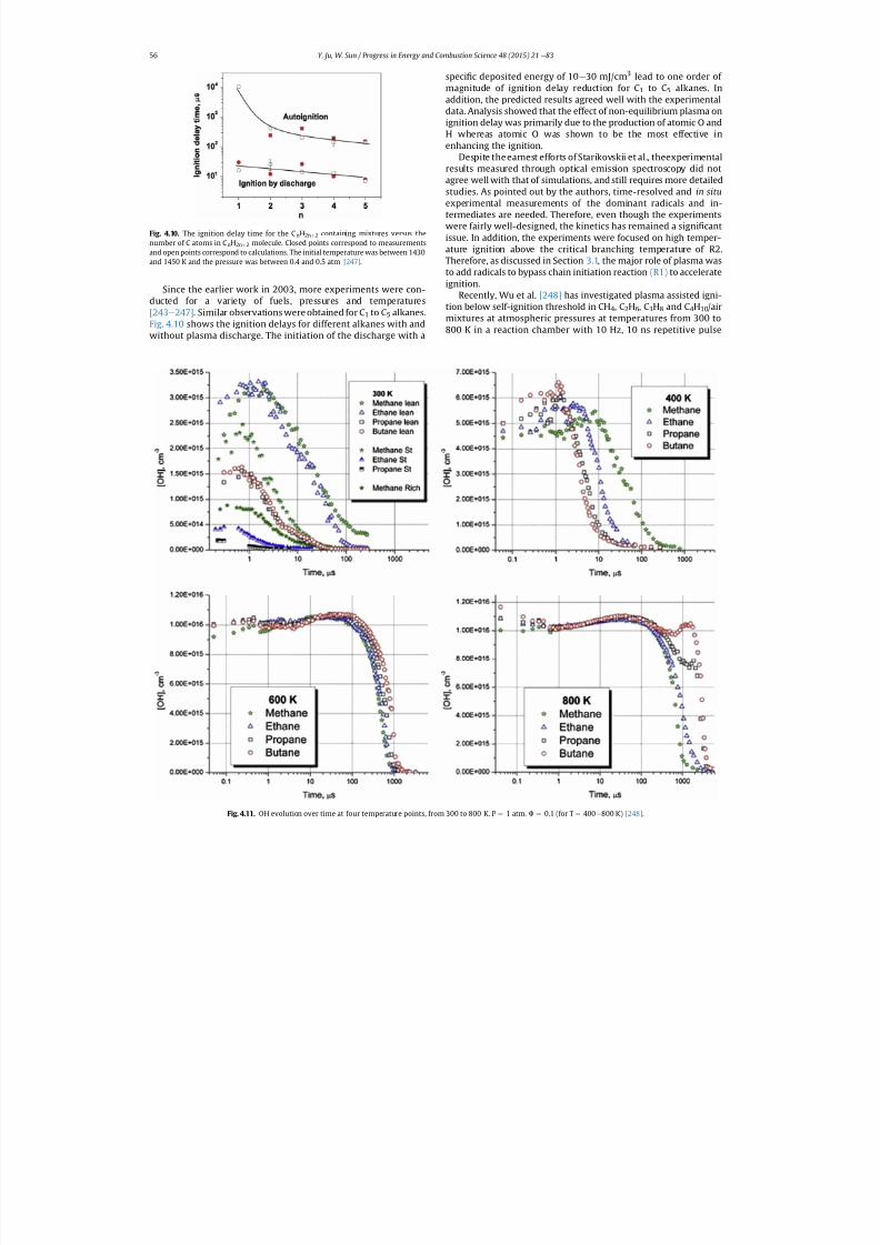
7/21/2019 Plasma Assisted Combustion Dynamics and Chemistry
http://slidepdf.com/reader/full/plasma-assisted-combustion-dynamics-and-chemistry 36/63
Since the earlier work in 2003, more experiments were con-ducted for a variety of fuels, pressures and temperatures[243 e 247] . Similar observations were obtained for C 1 to C5 alkanes.
Fig. 4.10 shows the ignition delays for different alkanes with andwithout plasma discharge. The initiation of the discharge with a
speci c deposited energy of 10 e 30 mJ/cm 3 lead to one order of magnitude of ignition delay reduction for C 1 to C5 alkanes. Inaddition, the predicted results agreed well with the experimentaldata. Analysis showed that the effect of non-equilibrium plasma onignition delay was primarily due to the production of atomic O andH whereas atomic O was shown to be the most effective inenhancing the ignition.
Despite the earnest efforts of Starikovskii et al., theexperimentalresults measured through optical emission spectroscopy did notagree well with that of simulations, and still requires more detailedstudies. As pointed out by the authors, time-resolved and in situexperimental measurements of the dominant radicals and in-termediates are needed. Therefore, even though the experimentswere fairly well-designed, the kinetics has remained a signi cantissue. In addition, the experiments were focused on high temper-ature ignition above the critical branching temperature of R2.Therefore, as discussed in Section 3.1, the major role of plasma wasto add radicals to bypass chain initiation reaction (R1) to accelerateignition.
Recently, Wu et al. [248] has investigated plasma assisted igni-tion below self-ignition threshold in CH 4, C2H6, C3H8 and C 4H10/airmixtures at atmospheric pressures at temperatures from 300 to800 K in a reaction chamber with 10 Hz, 10 ns repetitive pulse
Fig. 4.10. The ignition delay time for the C nH2n þ 2 containing mixtures versus thenumber of C atoms in C nH2n þ 2 molecule. Closed points correspond to measurementsand open points correspond to calculations. The initial temperature was between 1430and 1450 K and the pressure was between 0.4 and 0.5 atm [247] .
Fig. 4.11. OH evolution over time at four temperature points, from 300 to 800 K. P ¼
1 atm. F ¼
0.1 (for T ¼
400e
800 K) [248] .
Y. Ju, W. Sun / Progress in Energy and Combustion Science 48 (2015) 21 e 8356
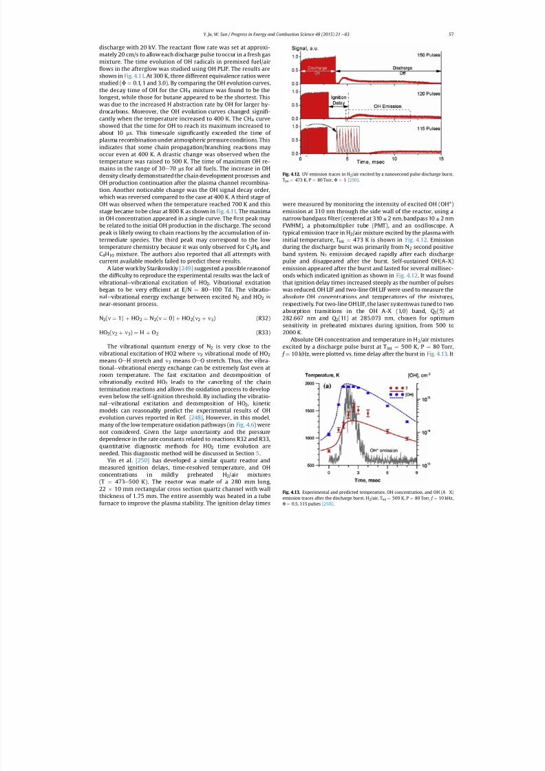
7/21/2019 Plasma Assisted Combustion Dynamics and Chemistry
http://slidepdf.com/reader/full/plasma-assisted-combustion-dynamics-and-chemistry 37/63
discharge with 20 kV. The reactant ow rate was set at approxi-mately 20 cm/s to allow each discharge pulse to occur in a fresh gasmixture. The time evolution of OH radicals in premixed fuel/air
ows in the afterglow was studied using OH PLIF. The results areshown in Fig. 4.11. At 300 K, three different equivalence ratios werestudied ( F ¼ 0.1, 1 and 3.0). By comparing the OH evolution curves,the decay time of OH for the CH 4 mixture was found to be thelongest, while those for butane appeared to be the shortest. Thiswas due to the increased H abstraction rate by OH for larger hy-drocarbons. Moreover, the OH evolution curves changed signi -cantly when the temperature increased to 400 K. The CH 4 curveshowed that the time for OH to reach its maximum increased toabout 10 ms. This timescale signi cantly exceeded the time of plasma recombination under atmospheric pressure conditions. Thisindicates that some chain propagation/branching reactions mayoccur even at 400 K. A drastic change was observed when thetemperature was raised to 500 K. The time of maximum OH re-mains in the range of 30 e 70 ms for all fuels. The increase in OHdensity clearly demonstrated the chain development processes andOH production continuation after the plasma channel recombina-tion. Another noticeable change was the OH signal decay order,which was reversed compared to the case at 400 K. A third stage of OH was observed when the temperature reached 700 K and thisstage became to be clear at 800 K as shown in Fig. 4.11. The maximain OH concentration appeared in a single curve. The rst peak maybe related to the initial OH production in the discharge. The secondpeak is likely owing to chain reactions by the accumulation of in-termediate species. The third peak may correspond to the lowtemperature chemistry because it was only observed for C 3H8 andC4H10 mixture. The authors also reported that all attempts withcurrent available models failed to predict these results.
A later work by Starikovskiy [249] suggested a possible reasonof the dif culty to reproduce the experimental results was the lack of vibrational e vibrational excitation of HO 2. Vibrational excitationbegan to be very ef cient at E/N ¼ 80 e 100 Td. The vibratio-nal e vibrational energy exchange between excited N 2 and HO 2 is
near-resonant process.
N2(n ¼ 1) þ HO2 ¼ N2(n ¼ 0) þ HO2(n2 þ n3) (R32)
HO2(n2 þ n3) ¼ H þ O2 (R33)
The vibrational quantum energy of N 2 is very close to thevibrational excitation of HO2 where n2 vibrational mode of HO 2means O e H stretch and n3 means O e O stretch. Thus, the vibra-tional e vibrational energy exchange can be extremely fast even atroom temperature. The fast excitation and decomposition of vibrationally excited HO 2 leads to the canceling of the chaintermination reactions and allows the oxidation process to developeven below the self-ignition threshold. By including the vibratio-
nale
vibrational excitation and decomposition of HO 2, kineticmodels can reasonably predict the experimental results of OHevolution curves reported in Ref. [248] . However, in this model,many of the low temperature oxidation pathways (in Fig. 4.6) werenot considered. Given the large uncertainty and the pressuredependence in the rate constants related to reactions R32 and R33,quantitative diagnostic methods for HO 2 time evolution areneeded. This diagnostic method will be discussed in Section 5 .
Yin et al. [250] has developed a similar quartz reactor andmeasured ignition delays, time-resolved temperature, and OHconcentrations in mildly preheated H 2/air mixtures(T ¼ 473 e 500 K). The reactor was made of a 280 mm long,22 10 mm rectangular cross section quartz channel with wallthickness of 1.75 mm. The entire assembly was heated in a tube
furnace to improve the plasma stability. The ignition delay times
were measured by monitoring the intensity of excited OH (OH*)emission at 310 nm through the side wall of the reactor, using anarrow bandpass lter (centered at 310 ± 2 nm, bandpass 10 ± 2 nmFWHM), a photomultiplier tube (PMT), and an oscilloscope. Atypical emission trace in H 2/air mixture excited by the plasma withinitial temperature, T ini ¼ 473 K is shown in Fig. 4.12 . Emissionduring the discharge burst was primarily from N 2 second positiveband system. N 2 emission decayed rapidly after each dischargepulse and disappeared after the burst. Self-sustained OH(A-X)emission appeared after the burst and lasted for several millisec-onds which indicated ignition as shown in Fig. 4.12 . It was foundthat ignition delay times increased steeply as the number of pulseswas reduced. OH LIF and two-line OH LIF were used to measure theabsolute OH concentrations and temperatures of the mixtures,
respectively. For two-line OH LIF, the laser systemwas tuned to twoabsorption transitions in the OH A-X (1,0) band, Q 1(5) at282.667 nm and Q 2(11) at 285.073 nm, chosen for optimumsensitivity in preheated mixtures during ignition, from 500 to2000 K.
Absolute OH concentration and temperature in H 2/air mixturesexcited by a discharge pulse burst at T ini ¼ 500 K, P ¼ 80 Torr, f ¼ 10 kHz, were plotted vs. time delay after the burst in Fig. 4.13 . It
Fig. 4.12. UV emission traces in H 2/air excited by a nanosecond pulse discharge burst,Tini ¼ 473 K, P ¼ 80 Torr, F ¼ 1 [250] .
Fig. 4.13. Experimental and predicted temperature, OH concentration, and OH (A e X)emission traces after the discharge burst, H 2/air, T ini ¼ 500 K, P ¼ 80 Torr, f ¼ 10 kHz,
F ¼
0.5, 115 pulses [250] .
Y. Ju, W. Sun / Progress in Energy and Combustion Science 48 (2015) 21 e 83 57
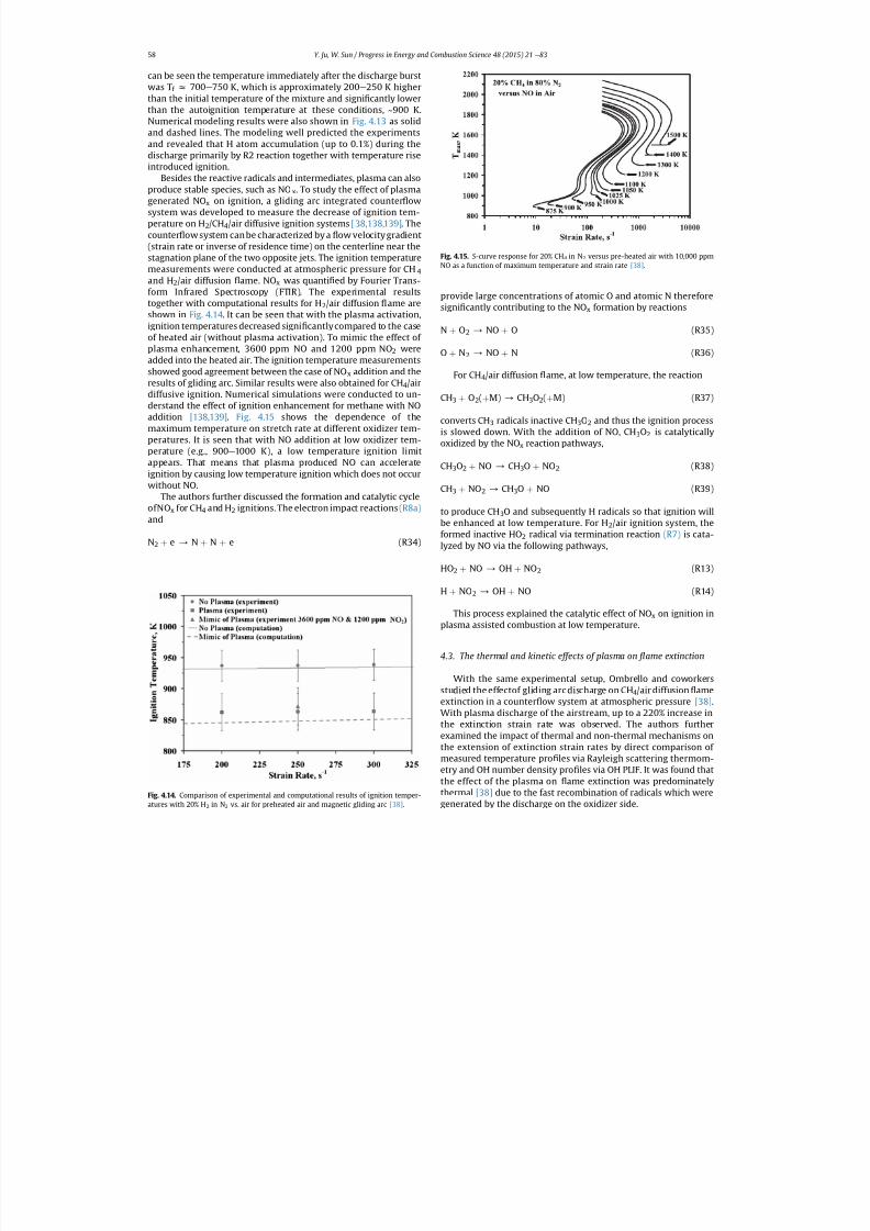
7/21/2019 Plasma Assisted Combustion Dynamics and Chemistry
http://slidepdf.com/reader/full/plasma-assisted-combustion-dynamics-and-chemistry 38/63
can be seen the temperature immediately after the discharge burstwas T f z 700 e 750 K, which is approximately 200 e 250 K higherthan the initial temperature of the mixture and signi cantly lowerthan the autoignition temperature at these conditions, ~900 K.Numerical modeling results were also shown in Fig. 4.13 as solidand dashed lines. The modeling well predicted the experimentsand revealed that H atom accumulation (up to 0.1%) during thedischarge primarily by R2 reaction together with temperature riseintroduced ignition.
Besides the reactive radicals and intermediates, plasma can alsoproduce stable species, such as NO x. To study the effect of plasmagenerated NO x on ignition, a gliding arc integrated counter owsystem was developed to measure the decrease of ignition tem-perature on H 2/CH4/air diffusive ignition systems [38,138,139] . Thecounter ow system can be characterized by a ow velocity gradient(strain rate or inverse of residence time) on the centerline near thestagnation plane of the two opposite jets. The ignition temperaturemeasurements were conducted at atmospheric pressure for CH 4and H 2/air diffusion ame. NO x was quanti ed by Fourier Trans-form Infrared Spectroscopy (FTIR). The experimental resultstogether with computational results for H 2/air diffusion ame areshown in Fig. 4.14 . It can be seen that with the plasma activation,ignition temperatures decreased signi cantlycompared to the caseof heated air (without plasma activation). To mimic the effect of plasma enhancement, 3600 ppm NO and 1200 ppm NO 2 wereadded into the heated air. The ignition temperature measurementsshowed good agreement between the case of NO x addition and theresults of gliding arc. Similar results were also obtained for CH 4/airdiffusive ignition. Numerical simulations were conducted to un-derstand the effect of ignition enhancement for methane with NOaddition [138,139] . Fig. 4.15 shows the dependence of themaximum temperature on stretch rate at different oxidizer tem-peratures. It is seen that with NO addition at low oxidizer tem-perature (e.g., 900 e 1000 K), a low temperature ignition limitappears. That means that plasma produced NO can accelerateignition by causing low temperature ignition which does not occur
without NO.The authors further discussed the formation and catalytic cycle
ofNO x for CH 4 and H 2 ignitions. The electron impact reactions (R8a)and
N2 þ e / N þ N þ e (R34)
provide large concentrations of atomic O and atomic N thereforesigni cantly contributing to the NO x formation by reactions
N þ O2 / NO þ O (R35)
O þ N2 / NO þ N (R36)
For CH4/air diffusion ame, at low temperature, the reaction
CH3 þ O2(þ M) / CH3O2(þ M) (R37)
converts CH 3 radicals inactive CH 3O2 and thus the ignition processis slowed down. With the addition of NO, CH 3O2 is catalyticallyoxidized by the NO x reaction pathways,
CH3O2 þ NO / CH3O þ NO2 (R38)
CH3 þ NO2 / CH3O þ NO (R39)
to produce CH 3O and subsequently H radicals so that ignition willbe enhanced at low temperature. For H 2/air ignition system, theformed inactive HO 2 radical via termination reaction (R7) is cata-lyzed by NO via the following pathways,
HO2 þ NO / OH þ NO2 (R13)
H þ NO2 / OH þ NO (R14)
This process explained the catalytic effect of NO x on ignition inplasma assisted combustion at low temperature.
4.3. The thermal and kinetic effects of plasma on ame extinction
With the same experimental setup, Ombrello and coworkersstudied the effectof gliding arc discharge on CH 4/air diffusion ameextinction in a counter ow system at atmospheric pressure [38] .With plasma discharge of the airstream, up to a 220% increase inthe extinction strain rate was observed. The authors furtherexamined the impact of thermal and non-thermal mechanisms onthe extension of extinction strain rates by direct comparison of measured temperature pro les via Rayleigh scattering thermom-etry and OH number density pro les via OH PLIF. It was found thatthe effect of the plasma on ame extinction was predominatelythermal [38] due to the fast recombination of radicals which were
generated by the discharge on the oxidizer side.
Fig. 4.14. Comparison of experimental and computational results of ignition temper-
atures with 20% H 2 in N2 vs. air for preheated air and magnetic gliding arc [38] .
Fig. 4.15. S -curve response for 20% CH 4 in N2 versus pre-heated air with 10,000 ppmNO as a function of maximum temperature and strain rate [38] .
Y. Ju, W. Sun / Progress in Energy and Combustion Science 48 (2015) 21 e 8358
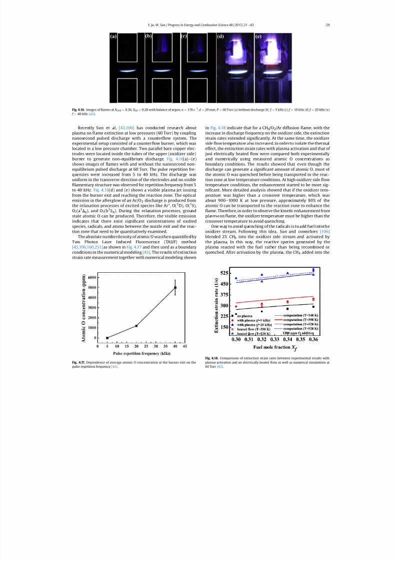
7/21/2019 Plasma Assisted Combustion Dynamics and Chemistry
http://slidepdf.com/reader/full/plasma-assisted-combustion-dynamics-and-chemistry 39/63
Recently Sun et al. [43,106] has conducted research aboutplasma on ame extinction at low pressures (60 Torr) by couplingnanosecond pulsed discharge with a counter ow system. Theexperimental setup consisted of a counter ow burner, which waslocated in a low pressure chamber. Two parallel bare copper elec-trodes were located inside the tubes of the upper (oxidizer side)burner to generate non-equilibrium discharge. Fig. 4.16(a) e (e)shows images of ames with and without the nanosecond non-equilibrium pulsed discharge at 60 Torr. The pulse repetition fre-quencies were increased from 5 to 40 kHz. The discharge wasuniform in the transverse direction of the electrodes and no visible
lamentary structure was observed for repetition frequency from 5to 40 kHz. Fig. 4.16 (d) and (e) shows a visible plasma jet issuingfrom the burner exit and reaching the reaction zone. The opticalemission in the afterglow of an Ar/O 2 discharge is produced fromthe relaxation processes of excited species like Ar*, O( 1D), O(1S),O2(a 1Dg), and O 2(b 1S g). During the relaxation processes, groundstate atomic O can be produced. Therefore, the visible emission
indicates that there exist signi cant concentrations of excitedspecies, radicals, and atoms between the nozzle exit and the reac-tion zone that need to be quantitatively examined.
The absolute numberdensity of atomic O wasthen quanti edbyTwo Photon Laser Induced Fluorescence (TALIF) method[43,106,160,251] as shown in Fig. 4.17 and then used as a boundaryconditions in the numerical modeling [43] . The results of extinctionstrain rate measurement together with numerical modeling shown
in Fig. 4.18 indicate that for a CH 4/O2/Ar diffusion ame, with theincrease in discharge frequency on the oxidizer side, the extinctionstrain rates extended signi cantly. At the same time, the oxidizerside ow temperature also increased. In orderto isolate the thermaleffect, the extinction strain rates with plasma activation and that of just electrically heated ow were compared both experimentallyand numerically using measured atomic O concentrations asboundary conditions. The results showed that even though thedischarge can generate a signi cant amount of atomic O, most of the atomic O was quenched before being transported to the reac-tion zone at low temperature conditions. At high oxidizer side owtemperature conditions, the enhancement started to be more sig-ni cant. More detailed analysis showed that if the oxidizer tem-perature was higher than a crossover temperature, which wasabout 900 e 1000 K at low pressure, approximately 80% of theatomic O can be transported to the reaction zone to enhance the
ame. Therefore, in order to observe the kinetic enhancement fromplasma on ame, the oxidizer temperature must be higher than the
crossover temperature to avoid quenching.One way to avoid quenching of the radicals is to add fuel intothe
oxidizer stream. Following this idea, Sun and coworkers [106]blended 2% CH 4 into the oxidizer side stream and activated bythe plasma. In this way, the reactive species generated by theplasma reacted with the fuel rather than being recombined orquenched. After activation by the plasma, the CH 4 added into the
Fig. 4.17. Dependence of average atomic O concentration at the burner exit on the
pulse repetition frequency [43] .
Fig. 4.16. Images of ames at X CH4 ¼ 0.36, X O2 ¼ 0.28 with balance of argon, a ¼ 178 s 1, d ¼ 20 mm, P ¼ 60 Torr (a) without discharge (b) f ¼ 5 kHz (c) f ¼ 10 kHz (d) f ¼ 20 kHz (e) f ¼ 40 kHz [43] .
Fig. 4.18. Comparisons of extinction strain rates between experimental results withplasma activation and an electrically heated ow as well as numerical simulations at
60 Torr [43] .
Y. Ju, W. Sun / Progress in Energy and Combustion Science 48 (2015) 21 e 83 59
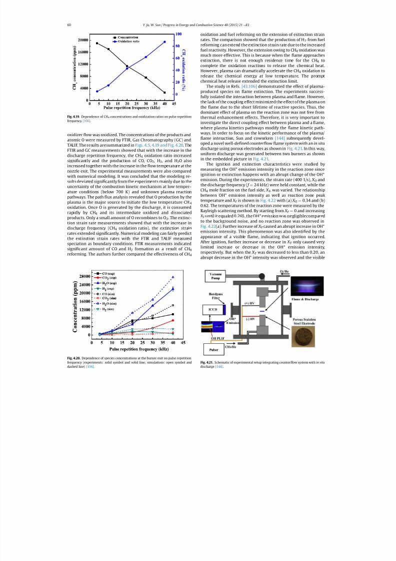
7/21/2019 Plasma Assisted Combustion Dynamics and Chemistry
http://slidepdf.com/reader/full/plasma-assisted-combustion-dynamics-and-chemistry 40/63
oxidizer ow was oxidized. The concentrations of the products andatomic O were measured by FTIR, Gas Chromatography (GC) and
TALIF. The results aresummarized in Figs. 4.5, 4.19 and Fig. 4.20 . TheFTIR and GC measurements showed that with the increase in thedischarge repetition frequency, the CH 4 oxidation ratio increasedsigni cantly and the production of CO, CO 2, H2, and H 2O alsoincreased together with the increase in the ow temperature at thenozzle exit. The experimental measurements were also comparedwith numerical modeling. It was concluded that the modeling re-sults deviated signi cantly from the experiments mainly due to theuncertainty of the combustion kinetic mechanism at low temper-ature conditions (below 700 K) and unknown plasma reactionpathways. The path ux analysis revealed that O production by theplasma is the major source to initiate the low temperature CH 4oxidation. Once O is generated by the discharge, it is consumedrapidly by CH 4 and its intermediate oxidized and dissociatedproducts. Only a small amount of O recombines to O 2. The extinc-tion strain rate measurements showed that with the increase indischarge frequency (CH 4 oxidation ratio), the extinction strainrates extended signi cantly. Numerical modeling can fairly predictthe extinction strain rates with the FTIR and TALIF measuredspeciation as boundary conditions. FTIR measurements indicatedsigni cant amount of CO and H 2 formation as a result of CH 4reforming. The authors further compared the effectiveness of CH 4
oxidation and fuel reforming on the extension of extinction strainrates. The comparison showed that the production of H 2 from fuelreforming can extend the extinction strain rate due to the increasedfuel reactivity. However, the extension owing to CH 4 oxidation wasmuch more effective. This is because when the ame approachesextinction, there is not enough residence time for the CH 4 tocomplete the oxidation reactions to release the chemical heat.However, plasma can dramatically accelerate the CH 4 oxidation torelease the chemical energy at low temperature. The promptchemical heat release extended the extinction limit.
The study in Refs. [43,106] demonstrated the effect of plasma-produced species on ame extinction. The experiments success-fully isolated the interaction between plasma and ame. However,the lack of the coupling effect minimized the effect of the plasma onthe ame due to the short lifetime of reactive species. Thus, thedominant effect of plasma on the reaction zone was not free fromthermal enhancement effects. Therefore, it is very important toinvestigate the direct coupling effect between plasma and a ame,where plasma kinetics pathways modify the ame kinetic path-ways. In order to focus on the kinetic performance of the plasma/
ame interaction, Sun and coworkers [144] subsequently devel-oped a novel well-de ned counter ow ame system with an in situdischarge using porous electrodes as shown in Fig. 4.21. In this way,uniform discharge was generated between two burners as shownin the embedded picture in Fig. 4.21.
The ignition and extinction characteristics were studied bymeasuring the OH* emission intensity in the reaction zone sinceignition or extinction happens with an abrupt change of the OH*emission. During the experiments, the strain rate (400 1/s), X O andthe discharge frequency ( f ¼ 24 kHz) were held constant, while theCH4 mole fraction on the fuel side, X F , was varied. The relationshipbetween OH* emission intensity as well as reaction zone peaktemperature and X F is shown in Fig. 4.22 with (a) X O ¼ 0.34 and (b)0.62. The temperatures of the reaction zone were measured by theRayleigh scattering method. By starting from X F ¼ 0 and increasing X F until it equaled 0.265, the OH* emission was negligiblecompared
to the background noise, and no reaction zone was observed inFig. 4.22 (a). Further increase of X F caused an abrupt increase in OH*emission intensity. This phenomenon was also identi ed by theappearance of a visible ame, indicating that ignition occurred.After ignition, further increase or decrease in X F only caused verylimited increase or decrease in the OH* emission intensity,respectively. But when the X F was decreased to less than 0.20, anabrupt decrease in the OH* intensity was observed and the visible
Fig. 4.21. Schematic of experimental setup integrating counter ow system with in situ
discharge [144] .
Fig. 4.20. Dependence of species concentrations at the burner exit on pulse repetitionfrequency (experiments: solid symbol and solid line; simulations: open symbol and
dashed line) [106] .
Fig. 4.19. Dependence of CH 4 concentrations and oxidization ratios on pulse repetitionfrequency [106] .
Y. Ju, W. Sun / Progress in Energy and Combustion Science 48 (2015) 21 e 8360
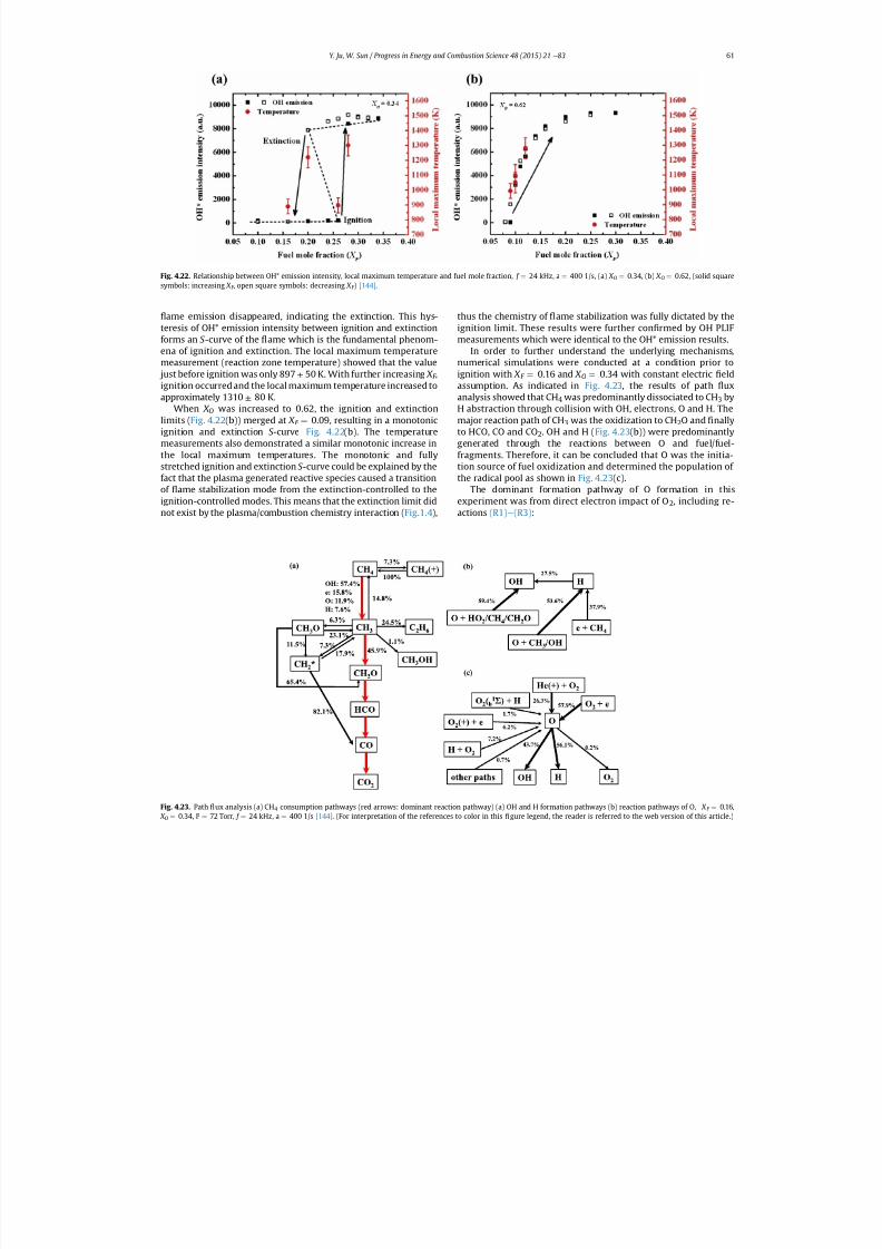
7/21/2019 Plasma Assisted Combustion Dynamics and Chemistry
http://slidepdf.com/reader/full/plasma-assisted-combustion-dynamics-and-chemistry 41/63
ame emission disappeared, indicating the extinction. This hys-
teresis of OH* emission intensity between ignition and extinctionforms an S -curve of the ame which is the fundamental phenom-ena of ignition and extinction. The local maximum temperaturemeasurement (reaction zone temperature) showed that the value just before ignition was only 897 ± 50 K. With further increasing X F ,ignition occurred and the local maximum temperature increased toapproximately 1310 ± 80 K.
When X O was increased to 0.62, the ignition and extinctionlimits ( Fig. 4.22 (b)) merged at X F ¼ 0.09, resulting in a monotonicignition and extinction S -curve Fig. 4.22(b). The temperaturemeasurements also demonstrated a similar monotonic increase inthe local maximum temperatures. The monotonic and fullystretched ignition and extinction S -curve could be explained by thefact that the plasma generated reactive species caused a transition
of ame stabilization mode from the extinction-controlled to theignition-controlled modes. This means that the extinction limit didnot exist by the plasma/combustion chemistry interaction ( Fig.1.4 ),
thus the chemistry of ame stabilization was fully dictated by the
ignition limit. These results were further con rmed by OH PLIFmeasurements which were identical to the OH* emission results.
In order to further understand the underlying mechanisms,numerical simulations were conducted at a condition prior toignition with X F ¼ 0.16 and X O ¼ 0.34 with constant electric eldassumption. As indicated in Fig. 4.23 , the results of path uxanalysis showed that CH 4 was predominantly dissociated to CH 3 byH abstraction through collision with OH, electrons, O and H. Themajor reaction path of CH 3 was the oxidization to CH 2O and nallyto HCO, CO and CO 2. OH and H ( Fig. 4.23 (b)) were predominantlygenerated through the reactions between O and fuel/fuel-fragments. Therefore, it can be concluded that O was the initia-tion source of fuel oxidization and determined the population of the radical pool as shown in Fig. 4.23 (c).
The dominant formation pathway of O formation in thisexperiment was from direct electron impact of O 2, including re-actions (R1) e (R3) :
Fig. 4.23. Path ux analysis (a) CH 4 consumption pathways (red arrows: dominant reaction pathway) (a) OH and H formation pathways (b) reaction pathways of O, X F ¼ 0.16,
X O ¼
0.34, P ¼
72 Torr, f ¼
24 kHz, a ¼
400 1/s [144] . (For interpretation of the references to color in this
gure legend, the reader is referred to the web version of this article.)
Fig. 4.22. Relationship between OH* emission intensity, local maximum temperature and fuel mole fraction, f ¼ 24 kHz, a ¼ 400 1/s, (a) X O ¼ 0.34, (b) X O ¼ 0.62, (solid squaresymbols: increasing X F , open square symbols: decreasing X F ) [144] .
Y. Ju, W. Sun / Progress in Energy and Combustion Science 48 (2015) 21 e 83 61
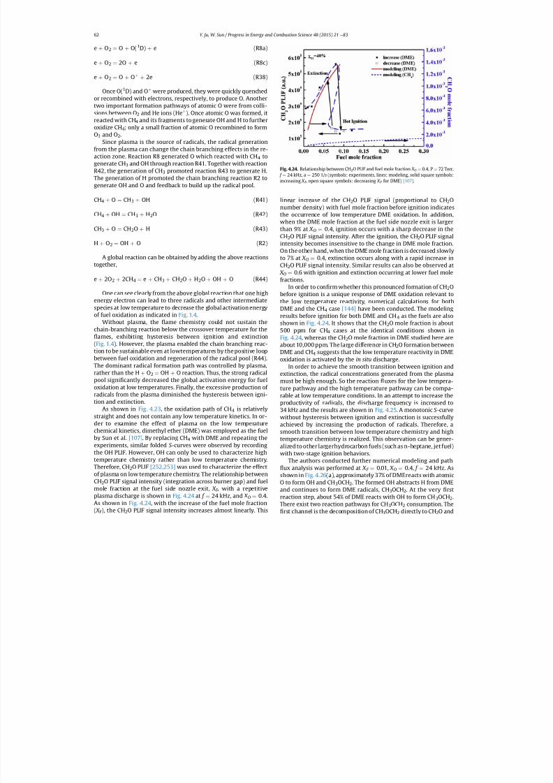
7/21/2019 Plasma Assisted Combustion Dynamics and Chemistry
http://slidepdf.com/reader/full/plasma-assisted-combustion-dynamics-and-chemistry 42/63
e þ O2 ¼ O þ O(1D) þ e (R8a)
e þ O2 ¼ 2O þ e (R8c)
e þ O2 ¼ O þ Oþ þ 2e (R38)
Once O( 1D) and O þ were produced, they were quickly quenchedor recombined with electrons, respectively, to produce O. Anothertwo important formation pathways of atomic O were from colli-sions between O 2 and He ions (He þ ). Once atomic O was formed, itreacted with CH 4 and its fragments to generate OH and H to furtheroxidize CH 4; only a small fraction of atomic O recombined to formO3 and O 2.
Since plasma is the source of radicals, the radical generationfrom the plasma can change the chain branching effects in the re-action zone. Reaction R8 generated O which reacted with CH 4 togenerate CH 3 and OH through reaction R41. Together with reactionR42, the generation of CH 3 promoted reaction R43 to generate H.The generation of H promoted the chain branching reaction R2 togenerate OH and O and feedback to build up the radical pool.
CH4 þ O ¼ CH3 þ OH (R41)
CH4 þ OH ¼ CH3 þ H2O (R42)
CH3 þ O ¼ CH2O þ H (R43)
H þ O2 ¼ OH þ O (R2)
A global reaction can be obtained by adding the above reactionstogether,
e þ 2O2 þ 2CH4 ¼ e þ CH3 þ CH2O þ H2O þ OH þ O (R44)
One can see clearly from the above global reaction that one highenergy electron can lead to three radicals and other intermediate
species at low temperature to decrease the global activation energyof fuel oxidation as indicated in Fig. 1.4 .
Without plasma, the ame chemistry could not sustain thechain-branching reaction below the crossover temperature for the
ames, exhibiting hysteresis between ignition and extinction(Fig. 1.4 ). However, the plasma enabled the chain branching reac-tion to be sustainable even at lowtemperatures by the positive loopbetween fuel oxidation and regeneration of the radical pool (R44).The dominant radical formation path was controlled by plasma,rather than the H þ O2 ¼ OH þ O reaction. Thus, the strong radicalpool signi cantly decreased the global activation energy for fueloxidation at low temperatures. Finally, the excessive production of radicals from the plasma diminished the hysteresis between igni-tion and extinction.
As shown in Fig. 4.23 , the oxidation path of CH 4 is relativelystraight and does not contain any low temperature kinetics. In or-der to examine the effect of plasma on the low temperaturechemical kinetics, dimethyl ether (DME) was employed as the fuelby Sun et al. [107] . By replacing CH 4 with DME and repeating theexperiments, similar folded S -curves were observed by recordingthe OH PLIF. However, OH can only be used to characterize hightemperature chemistry rather than low temperature chemistry.Therefore, CH 2O PLIF [252,253] was used to characterize the effectof plasma on low temperature chemistry. The relationship betweenCH2O PLIF signal intensity (integration across burner gap) and fuelmole fraction at the fuel side nozzle exit, X F , with a repetitiveplasma discharge is shown in Fig. 4.24 at f ¼ 24 kHz, and X O ¼ 0.4.As shown in Fig. 4.24 , with the increase of the fuel mole fraction( X
F ), the CH
2O PLIF signal intensity increases almost linearly. This
linear increase of the CH 2O PLIF signal (proportional to CH 2Onumber density) with fuel mole fraction before ignition indicatesthe occurrence of low temperature DME oxidation. In addition,when the DME mole fraction at the fuel side nozzle exit is largerthan 9% at X O ¼ 0.4, ignition occurs with a sharp decrease in theCH2O PLIF signal intensity. After the ignition, the CH 2O PLIF signalintensity becomes insensitive to the change in DME mole fraction.On the other hand, when the DME mole fraction is decreased slowlyto 7% at X O ¼ 0.4, extinction occurs along with a rapid increase inCH2O PLIF signal intensity. Similar results can also be observed at X O ¼ 0.6 with ignition and extinction occurring at lower fuel molefractions.
In order to con rm whether this pronounced formation of CH 2Obefore ignition is a unique response of DME oxidation relevant tothe low temperature reactivity, numerical calculations for both
DME and the CH 4 case [144] have been conducted. The modelingresults before ignition for both DME and CH 4 as the fuels are alsoshown in Fig. 4.24 . It shows that the CH 2O mole fraction is about500 ppm for CH 4 cases at the identical conditions shown inFig. 4.24 , whereas the CH 2O mole fraction in DME studied here areabout 10,000 ppm. The large difference in CH 2O formation betweenDME and CH 4 suggests that the low temperature reactivity in DMEoxidation is activated by the in situ discharge.
In order to achieve the smooth transition between ignition andextinction, the radical concentrations generated from the plasmamust be high enough. So the reaction uxes for the low tempera-ture pathway and the high temperature pathway can be compa-rable at low temperature conditions. In an attempt to increase theproductivity of radicals, the discharge frequency is increased to
34 kHz and the results are shown in Fig. 4.25 . A monotonic S -curvewithout hysteresis between ignition and extinction is successfullyachieved by increasing the production of radicals. Therefore, asmooth transition between low temperature chemistry and hightemperature chemistry is realized. This observation can be gener-alized to other largerhydrocarbon fuels (such as n-heptane, jet fuel)with two-stage ignition behaviors.
The authors conducted further numerical modeling and pathux analysis was performed at X F ¼ 0.01, X O ¼ 0.4, f ¼ 24 kHz. As
shown in Fig. 4.26 (a), approximately 37% of DMEreacts with atomicO to form OH and CH 3OCH2. The formed OH abstracts H from DMEand continues to form DME radicals, CH 3OCH2. At the very rstreaction step, about 54% of DME reacts with OH to form CH 3OCH2.There exist two reaction pathways for CH 3OCH2 consumption. The
rst channel is the decomposition of CH 3OCH2 directly to CH 2O and
Fig. 4.24. Relationship between CH 2O PLIF and fuel mole fraction X O ¼ 0.4, P ¼ 72 Torr, f ¼ 24 kHz, a ¼ 250 1/s (symbols: experiments, lines: modeling, solid square symbols:increasing X F , open square symbols: decreasing X F for DME) [107] .
Y. Ju, W. Sun / Progress in Energy and Combustion Science 48 (2015) 21 e 8362
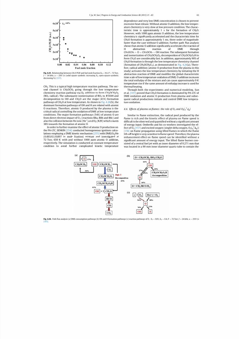
7/21/2019 Plasma Assisted Combustion Dynamics and Chemistry
http://slidepdf.com/reader/full/plasma-assisted-combustion-dynamics-and-chemistry 43/63
CH3. This is a typical high temperature reaction pathway. The sec-ond channel is CH 3OCH2 going through the low temperaturechemistry reaction pathway via O 2 addition to form CH 3OCH2O2(RO2 radical). The subsequent isomerization of RO 2 to R 0OOH anddecomposition to OH and CH 2O are the major (41%) formationpathways of CH 2O at low temperature. As shown in Fig. 4.26 (b), thedominant formation pathways of OH and H are related with atomicO reactions. Therefore, atomic O produced by the plasma is thecritical radical controlling the oxidation of DME at low temperatureconditions. The major formation pathways (54%) of atomic O arefrom direct electron impact of O 2 (reactions R8a, R8b and R8c) andalso the collision between He ions (He þ )andO 2 (R29) which counts38% towards the formation of atomic O.
In order to further examine the effect of atomic O production onthe PA-LTC, SENKIN [254] conducted homogeneous ignitions calcu-
lations employing a DME kinetic mechanism [255] with DME/O 2/He(0.003/0.1/0.897 in mole fraction) mixture and investigated at72 Torr, 650 K with and without 1000 ppm atomic O addition,respectively. The simulation is conducted at constant temperaturecondition to avoid further complicated kinetic temperature
dependence and very low DME concentration is chosen to preventexcessive heat release. Without atomic O addition, the low temper-ature chemistry is very slow at low pressure condition. The charac-teristic time is approximately 1 s for the formation of CH 2O.However, with 1000 ppm atomic O addition, the low temperaturechemistry is signi cantly accelerated and the characteristic time forCH2O formation is approximately 1 ms, three order of magnitudefaster than the case without O addition. Further path ux analysisshows that atomic O addition signi cantly accelerates the reaction of H abstraction reaction of DME throughCH3OCH3 þ O ¼ CH3OCH2 þ OH reaction. The subsequent formationand isomerization of CH 3OCH2O2, decomposition of CH 2OCH2O2H toform CH 2O are considerably fast. In addition, approximately 90% of CH2O formation is through the low temperature chemistry channel(formation of CH 3OCH2O2), as demonstrated in Fig. 4.26 (a). There-fore, radical addition (atomic O production from the plasma in thisstudy) activates the low temperature chemistry by initiating the Habstraction reaction of DME and modi es the global characteristictime scale of lowtemperature oxidation of DME. O addition increasesthe total enthalpy of the mixture and can cause approximately 9 Ktemperature rise if the same amount of enthalpy increase is used forthermal heating.
Through both the experiments and numerical modeling, Sunet al. [107] proved that CH 2O formation is dominated by PA-LTC of DME oxidation and atomic O production from plasma and subse-quent radical productions initiate and control DME low tempera-ture oxidation.
4.4. Effects of plasma on ames: the role of O 3 and O 2(a1D g )
Similar to ame extinction, the radical pool produced by theame is rich and the kinetic effect of plasma on ame speed is
dif cult to be observed and quanti ed without a signi cant amountof energy input. Ombrello and his co-workers investigated the ef-fect of O 3 [157] and excited oxygen (singlet delta oxygen, O 2(a
1Dg))[156] on ame propagation using lifted ames in which the amelift-off height is very sensitive to ame speed. Therefore, the plasmaenhancement effect on ame speed can be identi ed without asigni cant amount of energy input. The lifted ame burner con-sisted of a central fuel jet with an inner diameter of 0.271 mm thatwas located in a 90 mm inner diameter quartz tube to contain the
Fig. 4.26. Path ux analysis (a) DME consumption pathways (b) OH and H formation pathways (c) reaction pathways of O, X F ¼ 0.01, X O ¼ 0.4, P ¼ 72 Torr, f ¼ 24 kHz, a ¼ 250 1/s
[107] .
Fig. 4.25. Relationship between CH 2O PLIF and fuel mole fraction X O ¼ 0.6, P ¼ 72 Torr, f ¼ 34 kHz, a ¼ 250 1/s (solid square symbols: increasing X F , open square symbols:decreasing X F ) [107] .
Y. Ju, W. Sun / Progress in Energy and Combustion Science 48 (2015) 21 e 83 63
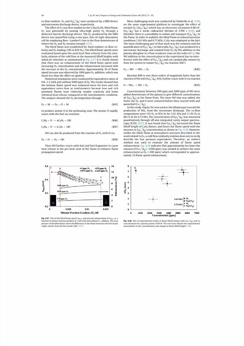
7/21/2019 Plasma Assisted Combustion Dynamics and Chemistry
http://slidepdf.com/reader/full/plasma-assisted-combustion-dynamics-and-chemistry 44/63
co- ow oxidizer. O 3 and O 2(a1Dg) were produced by a DBD device
and microwave discharge device, respectively.The effect of O 3 was rst studied on the C 3H8/O2/N2 lifted ame.
O3 was generated by passing ultra-high purity O 2 through adielectric barrier discharge device. The O 3 produced by the DBDdevice was quanti ed using a one-pass, line-of-sight absorptioncell by employing Beer e Lambert's law in the ow downstream of where the O 2 and N 2 streams merged [157] .
The lifted ame was established for xed oxidizer co- ow ve-locity and O 2 loading (18% in 82% N 2). The lifted ame speeds wereevaluated based upon the axial local ow velocity from the simi-larity solution of the cold ow at the measured liftoff heights withinitial jet velocities as summarized in Fig. 4.27. It is clearly shownthat there was an enhancement of the lifted ame speed withincreasing O 3 concentration and the enhancement increased withthe increase in the O 3 concentration. Approximately 3% of amespeed increase was observed by 1000 ppm O 3 addition, which wasmuch less than the effect on ignition.
Numerical simulations were conducted for equivalence ratios of 0.8 e 1.2 with and without 5000 ppm of O 3. The results showed thatthe laminar ame speed was enhanced more for lean and richequivalence ratios than at stoichiometric because lean and richpremixed ames have relatively weaker reactivity and lowerchemical heat release compared to the stoichiometric condition.The analysis showed the O 3 decomposition through
O3 þ M / O2 þ O þ M (R45)
to produce atomic O in the preheating zone. The atomic O rapidlyreacts with the fuel via reactions
C3H8 þ O / nC3H7 þ OH (R46)
C3H8 þ O / iC3H7 þ OH (R47)
OH can also be produced from the reaction of O 3 with H via
O3 þ H / O2 þ OH (R48)
Then OH further reacts with fuel and fuel fragments to causeheat release in the pre-heat zone of the ame to enhance amepropagation speed.
More challenging work was conducted by Ombrello et al. [156]on the same experimental platform to investigate the effect of excited O 2 (O2(a
1Dg)) which has an electronic excitation 0.98 eV.O2(a
1Dg) has a mean radioactive lifetime of 2700 s [256] andtherefore there is a possibility to isolate and transport O 2(a
1Dg) tothe ame. In order to stabilize the lifted ame at reduced pressureconditions (3.61 kPa and 6.73 kPa), C 2H4 was employed as the fuel.The most challenging part of that work was the isolation and thequanti cation of O 2(a
1Dg). In thatstudy, O 2(a1Dg) was produced in a
microwave discharge and isolated from O 3 by NO addition to theplasma afterglow in a ow residence time on the order of 1 s. TheNO addition in the concentration in the experiment has no inter-ference with the effect of O 2(a
1Dg) and can catalytically remove O 3from the system to isolate O 2(a
1Dg) via reaction (R47).
O3 þ NO / NO2 þ O2 (R49)
Reaction R49 is over three orders of magnitude faster than thereaction of NO with O 2(a
1Dg).NO2 further reacts with O via reaction
O þ NO2 / NO þ O2 (R50)
Concentrations between 500 ppm and 2000 ppm of NO wereadded downstream of the plasma to give different concentrationsof O2(a
1Dg) at the ame front. The more NO that was added, thefaster the O 3 and O were removed before they reacted with andquenched O 2(a
1Dg).In this study, Argon (Ar) was used as the dilution gas toavoid the
production of NO x from the microwave discharge. The co- owcompositions were 15% O 2 in 85% Ar for 3.61 kPa and 11.9% O 2 in88.1% Ar for 6.73 kPa. The concentration of O 2(a
1Dg) was measuredquantitatively through off-axis integrated cavity output spectros-copy (ICOS) [257] . It was found that O 2(a
1Dg) increased the ameliftoff height of C 2H4 ames, and hence the ame speed with theincrease in O 2(a
1Dg) concentration as shown in Fig. 4.28 . However,unlike the lifted ame at atmospheric pressure described in the
work related to O 3, a cold ow similarity solution does notcorrectlydescribe the low pressure experiments. Therefore, an indirectmethod was used to estimate the amount of ame speedenhancement. Fig. 4.28 indicates that approximately ten times theamount of O 2(a
1Dg) (~5500 ppm) was needed to achieve the sameenhancement as O 3 (~500 ppm) which corresponded to approxi-mately 1% ame speed enhancement.
Fig. 4.28. Plot of experimental results of ame liftoff change with O 2(a1Dg) and O 3
concentration for a plasma power of 80 W. The error bars denote the experimental
uncertainties in the concentrations and change in
ame liftoff height [156] .
Fig. 4.27. Plot of the lifted ame speed, S lifted , and percent enhancement of S lifted as afunction of mixture fraction gradient at 1 atm with and without O 3 addition. The insetpictures of the lifted ames show the differences in the ame front near the fuel nozzle
(right) and far from the fuel nozzle (left) [157] .
Y. Ju, W. Sun / Progress in Energy and Combustion Science 48 (2015) 21 e 8364
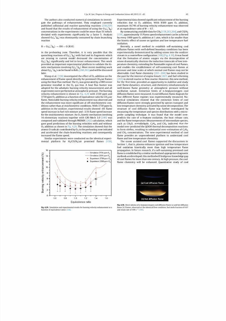
7/21/2019 Plasma Assisted Combustion Dynamics and Chemistry
http://slidepdf.com/reader/full/plasma-assisted-combustion-dynamics-and-chemistry 45/63
The authors also conducted numerical simulations to investi-gate the pathways of enhancement. They employed currentlypublished collisional and reactive quenching reactions [258,259]and found that the results of enhancement of using the O 2(a
1Dg)concentrations in the experiments could be more than 5% whichdeviated with experiments signi cantly by a factor 5. Analysisshowed O 2(a
1Dg) was dominantly consumed by chain branchingreaction
H þ O2(a1Dg) / OH þ O (R10)
in the preheating zone. Therefore, it is very possible that thequenching reactions of O 2(a
1Dg) with fuel and its fragments whichare missing in current model decreased the concentration of O2(a
1Dg) signi cantly and led to lesser enhancement. This workprovided an important experimental platform to validate the ki-netic mechanisms involving O 2(a
1Dg). More recent modeling workabout O 2(a
1Dg) can be found in Refs. [260,261] and will be discussedlater.
Wang et al. [158] investigated the effect of O 3 addition on theenhancement of ame speed directly for premixed CH 4/air amesusing the Heat Flux method. The O 3 was generated by a DBD ozonegenerator installed in the O 2 gas line. A heat ux burner wasadopted for the adiabatic burning velocity measurement and allexperiments were performed at atmospheric pressure. The burningvelocity enhancement is shown in Fig. 4.29 with 2330 ppm and3730 ppm O 3 addition as a function of equivalence ratio for CH 4/air
ame. Noticeable burning velocity enhancement was observed andthe enhancement was more signi cant at off-stoichiometric con-ditions rather than at stoichiometric conditions. With 3730 ppm O 3addition in the oxidizer, experimental results showed ~8% amespeed increase in fuel rich mixture and ~3.5% ame speed increasefor the stoichiometric mixture. An O 3 kinetic mechanism involving16 elementary reactions together with GRI-Mech 3.0 [240] wascomposed and validated through PREMIX [262] calculation, whichgave good predictions of the burning velocities with and without
O3 addition as shown in Fig. 4.29 . The simulation showed that theatomic O radicals contributed by O 3 in the preheating zone initiatedand accelerated the chain-branching reactions and consequentlyincreased the ame speed.
Similar experiments were conducted on the identical experi-mental platform for H 2/CO/N 2/air premixed ames [159] .
Experimental data showed signi cant enhancement of the burningvelocities due to O 3 addition. With 8500 ppm O 3 addition,maximum 18.74% of burning velocity enhancement was observedat an equivalence ratio of F ¼ 0.7.
By summarizing available data for CH 4 [158,263,264] , and CO/H 2[159] , approximately 1% ame speed enhancement can be achievedby every 1000 ppm O 3 addition at 1 atm, which is far smaller thanthe kinetic effect of ozone on ignition and low temperature fueloxidation.
Recently, a novel method to establish self-sustaining cooldiffusion ames with well-de ned boundary conditions has beenexperimentally demonstrated by adding ozone into the oxidizerstream in a counter ow con guration [108] (Fig. 4.30 ). It was foundthat the formation of atomic oxygen via the decomposition of ozone dramatically shortens the induction timescale of low tem-perature chemistry, extending the ammable region of cool ames,and enables the establishment of self-sustaining cool ames atpressure and time scales at which normal cool ames may not beobservable. Cool ame chemistry [265 e 268] has been studied inthe past for the interest of engine knock [267] and fuel reforming[265] in stirred reactor or ow reactor. However, this new method,for the rst time, provided an opportunity to stabilize and studycool ame dynamics, structure, and chemistry simultaneously inwell-known ame geometry at atmospheric pressure withoutoscillation nature. Extinction limits of n-heptane/oxygen cooldiffusion ames were measured. A cool diffusion ame diagram forfour different ame regimes was experimentally measured. Nu-merical simulations showed that the extinction limits of cooldiffusion ames were strongly governed by species transport andlow temperature chemistry activated by ozone decomposition. Thestructure of cool diffusion ame was further investigated bymeasuring the temperature and species distributions with a micro-probe sampling technique. It was found that the model over-predicts the rate of n-heptane oxidation, the heat release rate,and the ame temperature. Measurements of intermediate species,such as CH 2O, acetaldehyde, C 2H4, and CH 4 indicated that the
model over-predicted the QOOH thermal decomposition reactionsto form ole ns, resulting in substantial over-estimation of C 2H4,and CH 4 concentrations. The new experimental method of cool
ame provides an unprecedented platform to understand coolame and low temperature chemistry.
The ozone assisted cool ames supported the discussions inSection 3 , that is, plasma enhances ignition and low temperaturefuel oxidation kinetically more than high temperature amepropagation. In future research, if a self-sustaining premixed cool
ame is established by a similar methodand appropriate diagnosticmethods aredeveloped, this methodwill bridgeour knowledge gapof cool ames for more than one century. At high pressure, the cool
ame chemistry will be enhanced. Quantitative study of cool
Fig. 4.29. Simulation and experimental results for burning velocity enhancement as a
function of equivalence ratios [158] .
Fig. 4.30. Direct photos of n-heptane/oxygen cool diffusion ame (a) and hot diffusioname (b) ames, observed at the identical ow condition, fuel mole fraction of 0.07
and strain rate of 100 s1
[108] .
Y. Ju, W. Sun / Progress in Energy and Combustion Science 48 (2015) 21 e 83 65
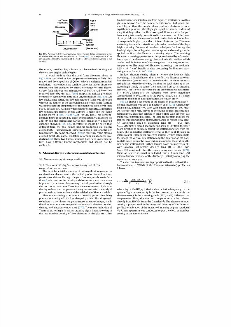
7/21/2019 Plasma Assisted Combustion Dynamics and Chemistry
http://slidepdf.com/reader/full/plasma-assisted-combustion-dynamics-and-chemistry 46/63
ames may provide a key solution to solve engine knocking anddevelop new engine technologies.
It is worth nothing that the cool ame discussed above inFig. 4.30 is controlled by low temperature chemistry of fuels (for-mation and decomposition of QOOH) which is different from fuel
oxidation at low temperature condition. Another type of direct lowtemperature fuel oxidation by plasma discharge for small hydro-carbon fuels without low temperature chemistry had been alsoreported before by Kim et al. [269] in a plasma assisted premixedcombustion system with ultra-lean CH 4/air mixture ( Fig. 4.31 ). Atlow equivalence ratios, this low temperature ame was observedwithout the ignition by the surrounding high temperature ame. Itwas found that the temperature of the ame could be lower than500 K. Because CH 4 has no low temperature chemistry, as reportedlow temperature ames by the authors is more like the ameregime shown in Figs. 1.4 and 4.22 b (for CH 4 also). This low tem-perature ame is initiated by direct O production via reactions R8and R9 and the subsequent partial fuel oxidation via reactionchannels shown in Fig. 4.23 . Therefore, it should be noted thatdifferent from the cool ames (radical production via plasmaassisted QOOH formation and isomerization) of n-heptane, the lowtemperature CH 4 ame observed [269] is more likely the plasmaassisted direct CH 4 partial oxidation/reforming via atomic O pro-duction [40] . These two ames, although both have low tempera-ture, have different kinetic mechanisms and should not beconfused.
5. Advanced diagnostics for plasma assisted combustion
5.1. Measurements of plasma properties
5.1.1. Thomson scattering for electron density and electrontemperature measurement
The most bene cial advantage of non-equilibrium plasma oncombustion enhancement is the radical production at low tem-perature conditions. Through the path ux analysis shown in Sec-tion 4.2 , electron numberdensity and electron temperature are twoimportant parameters determining radical production throughelectron impact reactions. Therefore, the measurement of electrondensity and electron temperature is very important for the study of plasma assisted combustion and the validation of kinetic models.
Thomson scattering is an elastic scattering process involvingphotons scattering off of a free charged particle. This diagnostictechnique is a non-intrusive, point measurement technique, and istherefore used to measure spatial and temporal electron numberdensity, and electron temperature [270] . The major limitation of Thomson scattering is its weak scattering signal intensity owing to
the low number density of free electrons in the plasma. Other
limitations include interference from Rayleigh scattering as well asplasma emission. Since the number densities of neutral species aremuch higher than the number density of free electrons in non-equilibrium plasmas, the Rayleigh signal is several orders of magnitude larger than the Thomson signal. However, since Dopplerbroadening is inversely proportional to the square root of the massof the particle, and the mass of neutral species is about four ordersof magnitude higher than that of free electrons, the Thomsonscattering line width is signi cantly broader than that of the Ray-leigh scattering. So several possible techniques for ltering theRayleigh signal, including selective absorption and masking, can beapplied to lter the Thomson scattering signal. The resultingThomson scattering spectrum can be approximated by a Gaussianline shape if the electron energy distribution is Maxwellian, whichcan be used for inference of the average electron energy (electrontemperature). The integrated Thomson scattering cross section is6.65 10 25 cm 2. Details on data processing for Thomson scat-tering can be found in Ref. [270] .
In low electron density plasmas, where the incident lightwavelength is much shorter than the effective distance betweenfree electrons (proportional to Debye length), the Thomson scat-tering is considered incoherent, and thus the total intensity of thescattering is simply the sum of the intensities from each scatteringelectron. This is often described by the dimensionless parametera ¼ 1 / (kl D), where k is the scattering wave vector magnitude(proportional to 1/ l ), and l D is the Debye length. If a << 1, freeelectrons and ions do not signi cantly affect each other.
Fig. 5.1 shows a schematic of the Thomson Scattering experi-mental setup that was used by Roettgen et al. [270] . A frequencydoubled (532 nm) Nd:YAG laser, with a pulse energy of ~600 mJ at30 Hz repetition rate, serves as the pump source. This beam isfocused into a glass test cell which can be lled with different gasmixtures at different pressures. The laser beam enters and exits thetest cell through windows at Brewster's angle to reduce stray light.An achromatic doublet collection lens (D ¼ 31.5 mm, f lens ¼ 200 mm) is placed at a scattering angle of 90 from the laser
beam direction to optimally collect the scattered photons from thebeam. The collimated scattering signal is then sent through animage rotator (three silver protected mirrors), which rotates boththe image (to vertical orientation) and the polarization (to hori-zontal), since horizontal polarization maximizes the grating ef -ciency. The scattered light is then focused down onto a vertical slitwith another achromatic doublet lens (D ¼ 31.5 mm, f lens ¼ 200 mm), and enters the triple grating spectrometer [271] .Thomson scattering signal is collected from a 3 mm long, ~60micron diameter volume of the discharge, spatially averaging thesignals over this region.
The electron temperature is proportional to the half-width athalf-maximum (HWHM) of the Thomson (Gaussian) pro le, asfollows:
D v 0D ¼
2 v 0c ffiffiffiffiffiffiffiffiffi2 ln ð2ÞkBT e
mes sinq2
(5.1)
where DnD0 is HWHM, n0 is the incident radiation frequency, c is the
speed of light in vacuum, kB is the Boltzmann constant, m e is theelectron mass, q is the scattering angle (90 ), and T e is the electrontemperature. Thus, the electron temperature can be inferreddirectly from HWHM from the Gaussian t. The electron numberdensity is proportional to the integrated intensity of the Thomsonpro le. So calibration of the integrated intensity by pure rotationalN2 Raman spectrum was conducted to put the electron number
density on an absolute scale.
Fig. 4.31. Plasma assisted CH 4/air premixed ame. The red dotted lines represent thevisible boundary of the low temperature CH 4 ame [269] . (For interpretation of thereferences to color in this gure legend, the reader is referred to the web version of thisarticle.)
Y. Ju, W. Sun / Progress in Energy and Combustion Science 48 (2015) 21 e 8366
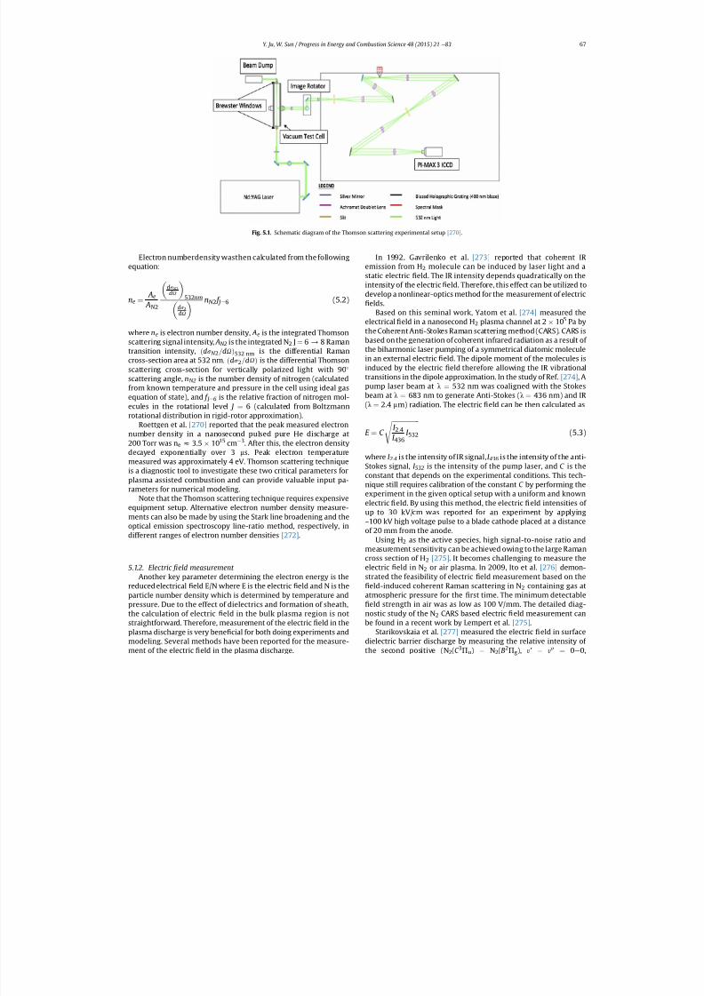
7/21/2019 Plasma Assisted Combustion Dynamics and Chemistry
http://slidepdf.com/reader/full/plasma-assisted-combustion-dynamics-and-chemistry 47/63
Electron numberdensity wasthen calculated from the followingequation:
ne ¼ Ae AN 2
ds N 2dU
532 nm
ds 2dU
nN 2 f J ¼6 (5.2)
where ne is electron number density, Ae is the integrated Thomsonscattering signal intensity, AN2 is the integrated N 2 J¼ 6 / 8 Ramantransition intensity, ðds N 2 =dU Þ532 nm is the differential Ramancross-section area at 532 nm, ðds 2 =dU Þ is the differential Thomsonscattering cross-section for vertically polarized light with 90scattering angle, nN2 is the number density of nitrogen (calculatedfrom known temperature and pressure in the cell using ideal gasequation of state), and f J ¼6 is the relative fraction of nitrogen mol-ecules in the rotational level J ¼ 6 (calculated from Boltzmannrotational distribution in rigid-rotor approximation).
Roettgen et al. [270] reported that the peak measured electronnumber density in a nanosecond pulsed pure He discharge at200 Torr was n e z 3.5 1015 cm 3. After this, the electron densitydecayed exponentially over 3 ms. Peak electron temperaturemeasured was approximately 4 eV. Thomson scattering techniqueis a diagnostic tool to investigate these two critical parameters forplasma assisted combustion and can provide valuable input pa-rameters for numerical modeling.
Note that the Thomson scattering technique requires expensiveequipment setup. Alternative electron number density measure-ments can also be made by using the Stark line broadening and theoptical emission spectroscopy line-ratio method, respectively, indifferent ranges of electron number densities [272] .
5.1.2. Electric eld measurement Another key parameter determining the electron energy is the
reduced electrical eld E/N where E is the electric eld and N is theparticle number density which is determined by temperature andpressure. Due to the effect of dielectrics and formation of sheath,the calculation of electric eld in the bulk plasma region is notstraightforward. Therefore, measurement of the electric eld in theplasma discharge is very bene cial for both doing experiments andmodeling. Several methods have been reported for the measure-
ment of the electric
eld in the plasma discharge.
In 1992, Gavrilenko et al. [273] reported that coherent IR emission from H 2 molecule can be induced by laser light and astatic electric eld. The IR intensity depends quadratically on theintensity of the electric eld. Therefore, this effect can be utilized todevelop a nonlinear-optics method for the measurement of electric
elds.Based on this seminal work, Yatom et al. [274] measured the
electrical eld in a nanosecond H 2 plasma channel at 2 10 5 Pa bythe Coherent Anti-Stokes Raman scattering method (CARS). CARS isbased on the generation of coherent infrared radiation as a result of the biharmonic laser pumping of a symmetrical diatomic moleculein an external electric eld. The dipole moment of the molecules isinduced by the electric eld therefore allowing the IR vibrationaltransitions in the dipole approximation. In the study of Ref. [274] , Apump laser beam at l ¼ 532 nm was coaligned with the Stokesbeam at l ¼ 683 nm to generate Anti-Stokes ( l ¼ 436 nm) and IR (l ¼ 2.4 mm) radiation. The electric eld can be then calculated as
E ¼ C ffiffiffiffiffiffiffiffiffiffiI 2 :4I 436
I 532s (5.3)
where I 2.4 is the intensity of IR signal, I 436 is the intensity of the anti-Stokes signal, I 532 is the intensity of the pump laser, and C is theconstant that depends on the experimental conditions. This tech-nique still requires calibration of the constant C by performing theexperiment in the given optical setup with a uniform and knownelectric eld. By using this method, the electric eld intensities of up to 30 kV/cm was reported for an experiment by applying
~100 kV high voltage pulse to a blade cathode placed at a distanceof 20 mm from the anode.Using H 2 as the active species, high signal-to-noise ratio and
measurement sensitivity can be achieved owing to the large Ramancross section of H 2 [275] . It becomes challenging to measure theelectric eld in N 2 or air plasma. In 2009, Ito et al. [276] demon-strated the feasibility of electric eld measurement based on the
eld-induced coherent Raman scattering in N 2 containing gas atatmospheric pressure for the rst time. The minimum detectable
eld strength in air was as low as 100 V/mm. The detailed diag-nostic study of the N 2 CARS based electric eld measurement canbe found in a recent work by Lempert et al. [275] .
Starikovskaia et al. [277] measured the electric eld in surfacedielectric barrier discharge by measuring the relative intensity of
the second positive (N 2(C 3
P u) N2(B2
P g), y' y00
¼ 0e
0,
Fig. 5.1. Schematic diagram of the Thomson scattering experimental setup [270] .
Y. Ju, W. Sun / Progress in Energy and Combustion Science 48 (2015) 21 e 83 67
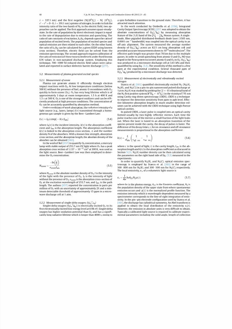
7/21/2019 Plasma Assisted Combustion Dynamics and Chemistry
http://slidepdf.com/reader/full/plasma-assisted-combustion-dynamics-and-chemistry 48/63
l ¼ 337.1 nm) and the rst negative (N 2þ (B2S u
þ ) N2þ ( X 2S g
þ ),y0 y00¼ 0 e 0, l ¼ 391.1 nm) systems of nitrogen. In order to link theintensity ratio of the two bands of N 2 to the electric eld, two ap-proaches can be applied. The rst approach assumes quasi-steady-state. So the rate of population by direct electronic impact is equalto the rate of depopulation due to emission and quenching. Theratio of rate constants of excitation, kC /kB, depends upon the ratioof population of excited levels. The population of excited species andoptical emission are then related to each other. On the other hand,the ratio of kC /kB can be calculated for a given EEDF using knowncross sections. Therefore, electric eld can be solved from theemission spectroscopy. The second approach requires calibration of the ratio of emissionsof these twoexcitedlevels under xed knownE/N values in non-sustained discharge system. Employing thistechnique, 700 e 1000 Td reduced electric eld values were calcu-lated and reported in surface dielectric barrier discharge [277] .
5.2. Measurements of plasma generated excited species
5.2.1. Measurement of ozonePlasma can generate atomic O ef ciently through electron
impact reactions with O 2. At low temperature conditions (below500 K) without the presence of fuel, atomic O recombines with O 2quickly to form ozone (O 3). O3 has very long lifetime which is of approximately 3 days at room temperature, 1.5 h at 400 K and1.5 s at 500 K. O 3 is one of the strongest oxidizers and can be ef -ciently produced at high pressure conditions. The concentration of O3 can be accurately quanti ed by absorption method.
Underconditions of weak absorption, the radiation intensity of alight source (e.g., lasers, lamps) I (v) transmitted through a homo-geneous gas sample is given by the Beer e Lambert Law:
I ðv Þ ¼ I 0 ðv Þexp ½ kðv Þlabs (5.4)
where I 0(v) is the incident intensity, k(v) is the absorption coef -cient and labs is the absorption length. The absorption coef cientk(v) is linked to the absorption cross section, s and the numberdensity N of the absorbers. With a known line strength, absorptioncross section, and the absorption length, the absolute density of theabsorber can be obtained [161] .
In the workof Ref. [157] to quantify O 3 concentration, a mercurylamp with stable output of 253.7 nm UV light where O 3 has a peakabsorption cross section of 1.137 10 17 cm 2 at 300 K, was used asthe light source. Beer e Lambert Law was then employed to deter-mine the O 3 concentration:
N ozone ¼ln I
I 0
s ozone labs(5.5)
where N ozone is the absolute number density of O 3, I is the intensityof the light with the presence of O 3, I 0 is the intensity of lightwithout the presence of O 3, s ozone is the absorption cross-section of O3 at the excitation wavelength of 253.7 nm, and labs is the pathlength. The authors [157] reported the concentration in parts permillion of O 3 with an uncertainty of approximately 2% and a min-imum detectable threshold of approximately 15 ppm in a micro-wave discharge cell at 1 atm.
5.2.2. Measurement of singlet delta oxygen, O 2(a1D g )
Singlet delta oxygen (O 2(a1Dg)) is electrically excited O 2 to its
rst electronically excited low-energy level at 0.98 eV. Singlet deltaoxygen has higher oxidation potential than O 2 and has a signi -
cantly long radiative lifetime which is longer than 4000 s, owing to
a spin forbidden transition to the ground state. Therefore, it hasattracted much attention.
In the work conducted by Ombrello et al. [156] , IntegratedCavity Output Spectroscopy (ICOS) [257] was adopted to obtain theabsolute concentrations of O 2(a
1Dg) by measuring absorptionfeature of the (1,0) band of the b
1S gþ
a1Dg Noxon system. A single-
mode, ber-pigtailed distributed-feedback diode laser (1505 nm,0.0001 cm 1 bandwidth) was coupled into the optical cavity in anoff-axis alignment. The system measured the average numberdensity of O 2(a
1Dg) across an 82.5 cm long absorption cell andprovided accurate measurements down to 10 14 molecules/cm 3. Theeffective path length was greater than 78 km due to the multiplepasses. In order to avoid quenching from atomic O and O 3, NO wasdoped in the owsystem toconvert atomic O and O 3 to O 2. O2(a
1Dg)was produced in a microwave discharge cell at 3.61 kPa and thenquanti ed by using Eq. (5.5) . The sensitivity of this method is a fewppm at the experimental condition. Several thousand ppm of O2(a
1Dg) produced by a microwave discharge was detected.
5.2.3. Measurement of electronically and vibrationally excitednitrogen
Stancu et al. [161] quanti ed electronically excited N 2 (N2( A),N2(B), and N 2(C )) in a pin-to-pin nanosecond pulsed discharge at1atm.N 2( A) was studied by probingthe (2 ) 0) vibrational band of the N 2 rst positive system(B 3P g ) A3S u
þ ) in the vicinityof 770 nmusing Cavity ring-down spectroscopy (CRDS). CRDS is a techniqueto improve the detection sensitivity from ppm to ppb level. Effec-tive kilometer-absorption lengths in much smaller detection vol-umes can be achieved with the CRDS technique using high- nesseoptical cavities.
In pulsed CRDS, a laser pulse is coupled into an optical cavityformed usually by two highly re ective mirrors. Each time thepulse reaches one of the mirrors a small fraction of the light leaksout. When the laser is tuned to an absorption transition of thespecies present inside the cavity, the decay of pulses is faster. Thedifference of the decay times, t , for on-resonance and off-resonancemeasurements is proportional to the absorption coef cient:
kðv Þ ¼ Lclabs
1t off res
1t on res! (5.6)
where c is the speed of light, L is the cavity length, labs is the ab-sorption lengthand k(v) is the absorption coef cient as discussed inSection 5.2.1. N2( A) number density can be then calculated usingthe parameters on the right hand side of Eq. (5.5) measured in theexperiments.
In order to quantify N 2(B), and N 2(C ), optical emission spec-troscopy is employed by Stancu et al. [161] in the range of 500 e 800 nm for N 2(B), and 300 e 500 nm for N 2(C ), respectively.The local emissivity, e l , of a volumetric light source is
el ¼ 14p
hv A21 N 2 f ðl Þ (5.7)
where hv is the photon energy, A 21 is the Einstein coef cient, N 2 isthe population density of the upper state from where spontaneousemission occurs and f (l ) is the normalized pro le function. Theemission intensity which is wavelength-dependent measured by aspectrometer corresponds to the line-of-sight integration of emis-sivity. In the pin e pin electrode con guration used by Stancu et al.[161] , the discharge has cylindrical symmetry. An Abel transform isapplied to obtain the local distribution of the emissivity el (r ).However, the emission in absolute units is very dif cult to obtain.Typically a calibrated light source is required to calibrate experi-
mental parameters including the solid angle, length of collection
Y. Ju, W. Sun / Progress in Energy and Combustion Science 48 (2015) 21 e 8368
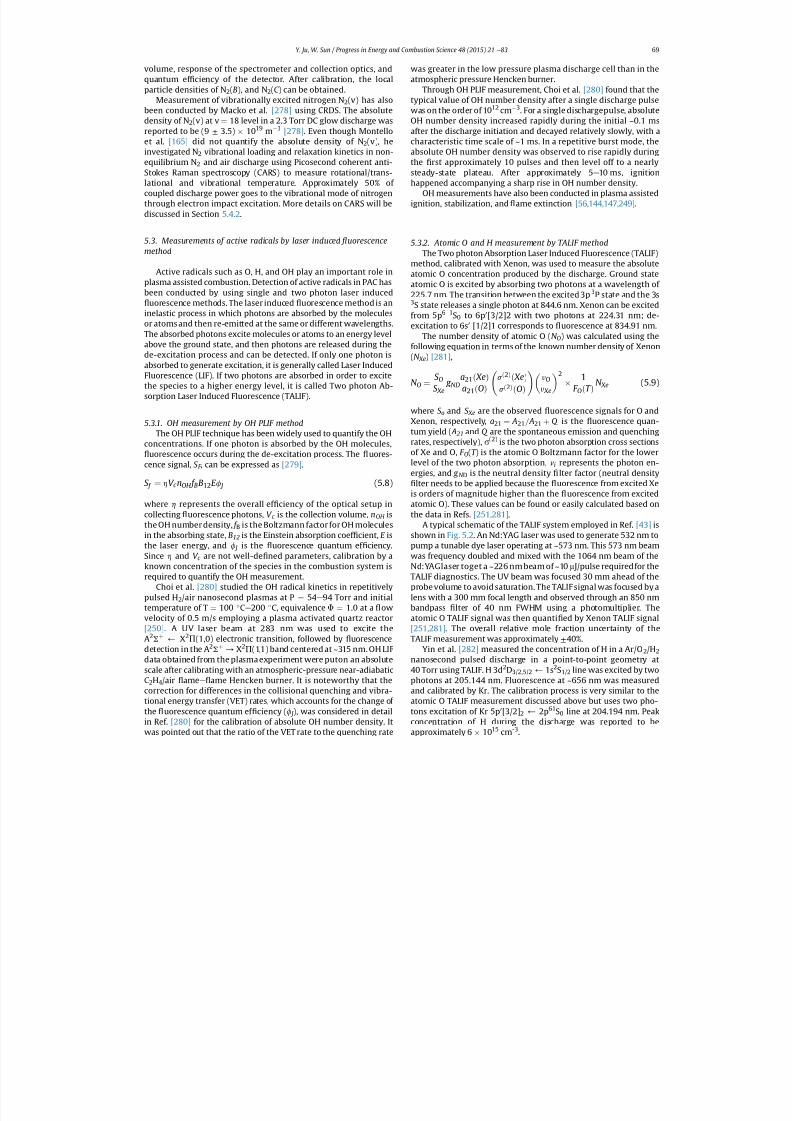
7/21/2019 Plasma Assisted Combustion Dynamics and Chemistry
http://slidepdf.com/reader/full/plasma-assisted-combustion-dynamics-and-chemistry 49/63
volume, response of the spectrometer and collection optics, andquantum ef ciency of the detector. After calibration, the localparticle densities of N 2(B), and N 2(C ) can be obtained.
Measurement of vibrationally excited nitrogen N 2(v) has alsobeen conducted by Macko et al. [278] using CRDS. The absolutedensity of N 2(v) at v ¼ 18 level in a 2.3 Torr DC glow discharge wasreported to be (9 ± 3.5) 10 19 m 3 [278] . Even though Montelloet al. [165] did not quantify the absolute density of N 2(v), heinvestigated N 2 vibrational loading and relaxation kinetics in non-equilibrium N 2 and air discharge using Picosecond coherent anti-Stokes Raman spectroscopy (CARS) to measure rotational/trans-lational and vibrational temperature. Approximately 50% of coupled discharge power goes to the vibrational mode of nitrogenthrough electron impact excitation. More details on CARS will bediscussed in Section 5.4.2 .
5.3. Measurements of active radicals by laser induced uorescencemethod
Active radicals such as O, H, and OH play an important role inplasma assisted combustion. Detection of active radicals in PAC has
been conducted by using single and two photon laser induceduorescence methods. The laser induced uorescence method is an
inelastic process in which photons are absorbed by the moleculesor atoms and then re-emitted at the same or different wavelengths.The absorbed photons excite molecules or atoms to an energy levelabove the ground state, and then photons are released during thede-excitation process and can be detected. If only one photon isabsorbed to generate excitation, it is generally called Laser InducedFluorescence (LIF). If two photons are absorbed in order to excitethe species to a higher energy level, it is called Two photon Ab-sorption Laser Induced Fluorescence (TALIF).
5.3.1. OH measurement by OH PLIF methodThe OH PLIF technique has been widely used to quantify the OH
concentrations. If one photon is absorbed by the OH molecules,uorescence occurs during the de-excitation process. The uores-
cence signal, S F , can be expressed as [279] .
S f ¼ h V c nOH f BB12 E f J (5.8)
where h represents the overall ef ciency of the optical setup incollecting uorescence photons, V c is the collection volume, nOH isthe OH number density, f B is the Boltzmann factor for OH moleculesin the absorbing state, B12 is the Einstein absorption coef cient, E isthe laser energy, and f J is the uorescence quantum ef ciency.Since h and V c are not well-de ned parameters, calibration by aknown concentration of the species in the combustion system isrequired to quantify the OH measurement.
Choi et al. [280] studied the OH radical kinetics in repetitivelypulsed H 2/air nanosecond plasmas at P ¼ 54 e 94 Torr and initialtemperature of T ¼ 100 Ce 200 C, equivalence F ¼ 1.0 at a owvelocity of 0.5 m/s employing a plasma activated quartz reactor[250] . A UV laser beam at 283 nm was used to excite theA2S þ ) X2P (1,0) electronic transition, followed by uorescencedetection in the A 2S þ / X2P (1,1) band centered at ~315 nm. OH LIFdata obtained from the plasma experiment were puton an absolutescale after calibrating with an atmospheric-pressure near-adiabaticC2H4/air ame e ame Hencken burner. It is noteworthy that thecorrection for differences in the collisional quenching and vibra-tional energy transfer (VET) rates, which accounts for the change of the uorescence quantum ef ciency ( f J ), was considered in detailin Ref. [280] for the calibration of absolute OH number density. It
was pointed out that the ratio of the VET rate to the quenching rate
was greater in the low pressure plasma discharge cell than in theatmospheric pressure Hencken burner.
Through OH PLIF measurement, Choi et al. [280] found that thetypical value of OH number density after a single discharge pulsewas on the order of 10 12 cm 3. For a single dischargepulse, absoluteOH number density increased rapidly during the initial ~0.1 msafter the discharge initiation and decayed relatively slowly, with acharacteristic time scale of ~1 ms. In a repetitive burst mode, theabsolute OH number density was observed to rise rapidly duringthe rst approximately 10 pulses and then level off to a nearlysteady-state plateau. After approximately 5 e 10 ms, ignitionhappened accompanying a sharp rise in OH number density.
OH measurements have also been conducted in plasma assistedignition, stabilization, and ame extinction [56,144,147,249] .
5.3.2. Atomic O and H measurement by TALIF methodThe Two photon Absorption Laser Induced Fluorescence (TALIF)
method, calibrated with Xenon, was used to measure the absoluteatomic O concentration produced by the discharge. Ground stateatomic O is excited by absorbing two photons at a wavelength of
225.7 nm. The transition between the excited 3p 3P state and the 3s3S state releases a single photon at 844.6 nm. Xenon can be excitedfrom 5p 6 1S0 to 6p 0[3/2]2 with two photons at 224.31 nm; de-excitation to 6s 0 [1/2]1 corresponds to uorescence at 834.91 nm.
The number density of atomic O ( N O) was calculated using thefollowing equation in terms of the known number density of Xenon(N Xe) [281] ,
N O ¼ S OS Xe
g NDa21 ð XeÞa 21 ðOÞ
s ð2Þð XeÞs ð2ÞðOÞ! yO
y Xe
2 1F OðT Þ
N Xe (5.9)
where S o and S Xe are the observed uorescence signals for O andXenon, respectively, a21 ¼ A21 = A21 þ Q is the uorescence quan-tum yield ( A 21 and Q are the spontaneous emission and quenching
rates, respectively), s (2) is the two photon absorption cross sectionsof Xe and O, F O(T ) is the atomic O Boltzmann factor for the lowerlevel of the two photon absorption, ni represents the photon en-ergies, and g N D is the neutral density lter factor (neutral density
lter needs to be applied because the uorescence from excited Xeis orders of magnitude higher than the uorescence from excitedatomic O). These values can be found or easily calculated based onthe data in Refs. [251,281] .
A typical schematic of the TALIF system employed in Ref. [43] isshown in Fig. 5.2. An Nd:YAG laser was used to generate 532 nm topump a tunable dye laser operating at ~573 nm. This 573 nm beamwas frequency doubled and mixed with the 1064 nm beam of theNd:YAGlaser toget a ~226 nm beam of ~10 m J/pulse requiredfor theTALIF diagnostics. The UV beam was focused 30 mm ahead of the
probe volume to avoid saturation. The TALIF signal was focused by alens with a 300 mm focal length and observed through an 850 nmbandpass lter of 40 nm FWHM using a photomultiplier. Theatomic O TALIF signal was then quanti ed by Xenon TALIF signal[251,281] . The overall relative mole fraction uncertainty of theTALIF measurement was approximately ± 40%.
Yin et al. [282] measured the concentration of H in a Ar/O 2/H 2nanosecond pulsed discharge in a point-to-point geometry at40 Torr using TALIF. H 3d 2D3/2,5/2 ) 1s 2S1/2 line was excited by twophotons at 205.144 nm. Fluorescence at ~656 nm was measuredand calibrated by Kr. The calibration process is very similar to theatomic O TALIF measurement discussed above but uses two pho-tons excitation of Kr 5p 0[3/2] 2 ) 2p 61 S0 line at 204.194 nm. Peakconcentration of H during the discharge was reported to be
approximately 6 1015
cm-3
.
Y. Ju, W. Sun / Progress in Energy and Combustion Science 48 (2015) 21 e 83 69
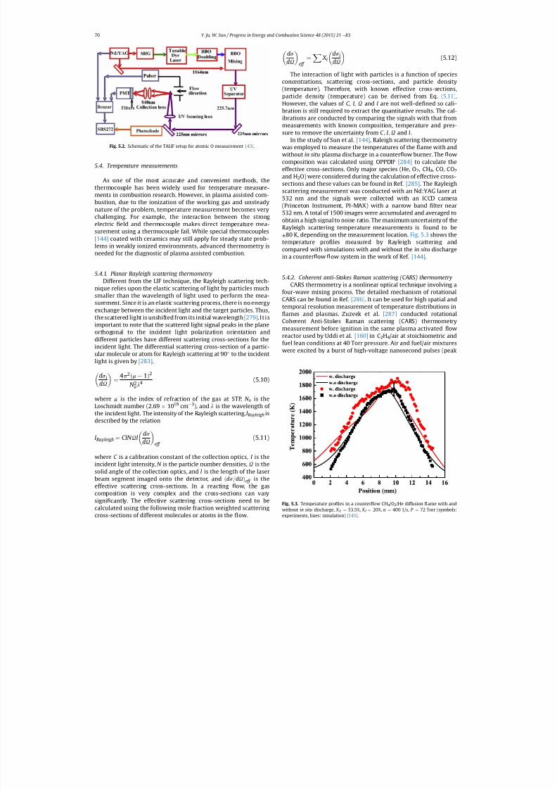
7/21/2019 Plasma Assisted Combustion Dynamics and Chemistry
http://slidepdf.com/reader/full/plasma-assisted-combustion-dynamics-and-chemistry 50/63
5.4. Temperature measurements
As one of the most accurate and convenient methods, thethermocouple has been widely used for temperature measure-ments in combustion research. However, in plasma assisted com-bustion, due to the ionization of the working gas and unsteadynature of the problem, temperature measurement becomes verychallenging. For example, the interaction between the strongelectric eld and thermocouple makes direct temperature mea-surement using a thermocouple fail. While special thermocouples[144] coated with ceramics may still apply for steady state prob-lems in weakly ionized environments, advanced thermometry isneeded for the diagnostic of plasma assisted combustion.
5.4.1. Planar Rayleigh scattering thermometryDifferent from the LIF technique, the Rayleigh scattering tech-
nique relies upon the elastic scattering of light by particles muchsmaller than the wavelength of light used to perform the mea-surement. Since it is an elastic scattering process, there is no energy
exchange between the incident light and the target particles. Thus,the scattered light is unshifted from its initial wavelength [279] . I t i simportant to note that the scattered light signal peaks in the planeorthogonal to the incident light polarization orientation anddifferent particles have different scattering cross-sections for theincident light. The differential scattering cross-section of a partic-ular molecule or atom for Rayleigh scattering at 90 to the incidentlight is given by [283] .
ds idU
¼ 4p 2 ðm 1Þ2
N 2o l 4 (5.10)
where m is the index of refraction of the gas at STP, N o is theLoschmidt number (2.69 1019 cm 3), and l is the wavelength of
the incident light. The intensity of the Rayleigh scattering, I Rayleigh isdescribed by the relation
I Rayleigh ¼ CIN U lds
dU eff (5.11)
where C is a calibration constant of the collection optics, I is theincident light intensity, N is the particle number densities, U is thesolid angle of the collection optics, and l is the length of the laserbeam segment imaged onto the detector, and ðds =dU Þeff is theeffective scattering cross-sections. In a reacting ow, the gascomposition is very complex and the cross-sections can varysigni cantly. The effective scattering cross-sections need to becalculated using the following mole fraction weighted scattering
cross-sections of different molecules or atoms in the
ow.
ds
dU eff ¼ X X i
ds idU
(5.12)
The interaction of light with particles is a function of speciesconcentrations, scattering cross-sections, and particle density(temperature). Therefore, with known effective cross-sections,particle density (temperature) can be derived from Eq. (5.11) .
However, the values of C , I , U and l are not well-de ned so cali-bration is still required to extract the quantitative results. The cal-ibrations are conducted by comparing the signals with that frommeasurements with known composition, temperature and pres-sure to remove the uncertainty from C , I , U and l.
In the study of Sun et al. [144] , Raleigh scattering thermometrywas employed to measure the temperatures of the ame with andwithout in situ plasma discharge in a counter ow burner. The owcomposition was calculated using OPPDIF [284] to calculate theeffective cross-sections. Only major species (He, O 2, CH4, CO, CO2and H 2O) were considered during the calculation of effective cross-sections and these values can be found in Ref. [285] . The Rayleighscattering measurement was conducted with an Nd:YAG laser at532 nm and the signals were collected with an ICCD camera
(Princeton Instrument, PI-MAX) with a narrow band lter near532 nm. A total of 1500 images were accumulated and averaged toobtain a high signal to noise ratio. The maximum uncertainty of theRayleigh scattering temperature measurements is found to be± 80 K, depending on the measurement location. Fig. 5.3 shows thetemperature pro les measured by Rayleigh scattering andcompared with simulations with and without the in situ dischargein a counter ow ow system in the work of Ref. [144] .
5.4.2. Coherent anti-Stokes Raman scattering (CARS) thermometryCARS thermometry is a nonlinear optical technique involving a
four-wave mixing process. The detailed mechanism of rotationalCARS can be found in Ref. [286] . It can be used for high spatial andtemporal resolution measurement of temperature distributions in
ames and plasmas. Zuzeek et al. [287] conducted rotationalCoherent Anti-Stokes Raman scattering (CARS) thermometrymeasurement before ignition in the same plasma activated owreactor used by Uddi et al. [160] in C2H4/air at stoichiometric andfuel lean conditions at 40 Torr pressure. Air and fuel/air mixtureswere excited by a burst of high-voltage nanosecond pulses (peak
Fig. 5.3. Temperature pro les in a counter ow CH4/O2/He diffusion ame with andwithout in situ discharge, X O ¼ 53.5%, X f ¼ 20%, a ¼ 400 1/s, P ¼ 72 Torr (symbols:
experiments, lines: simulation) [145] .
Fig. 5.2. Schematic of the TALIF setup for atomic O measurement [43] .
Y. Ju, W. Sun / Progress in Energy and Combustion Science 48 (2015) 21 e 8370
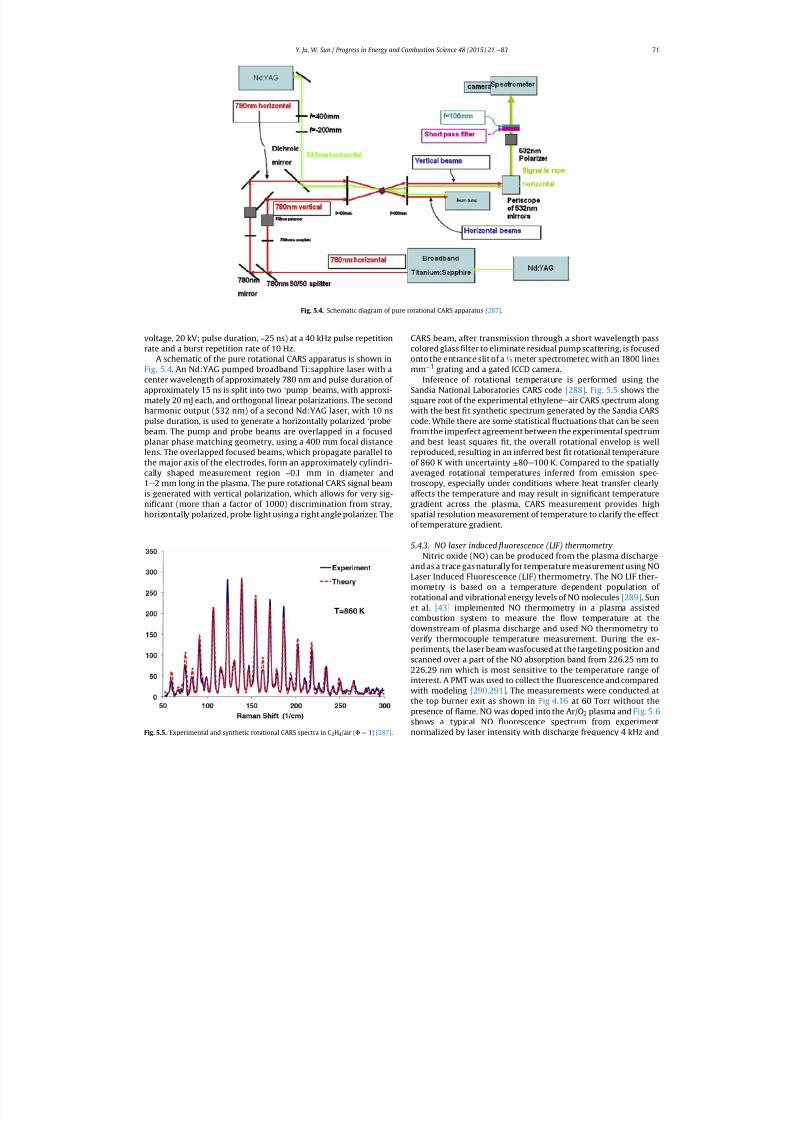
7/21/2019 Plasma Assisted Combustion Dynamics and Chemistry
http://slidepdf.com/reader/full/plasma-assisted-combustion-dynamics-and-chemistry 51/63
voltage, 20 kV; pulse duration, ~25 ns) at a 40 kHz pulse repetitionrate and a burst repetition rate of 10 Hz.
A schematic of the pure rotational CARS apparatus is shown inFig. 5.4 . An Nd:YAG pumped broadband Ti:sapphire laser with acenter wavelength of approximately 780 nm and pulse duration of approximately 15 ns is split into two ‘ pump ’ beams, with approxi-mately 20 mJ each, and orthogonal linear polarizations. The secondharmonic output (532 nm) of a second Nd:YAG laser, with 10 nspulse duration, is used to generate a horizontally polarized ‘ probe ’
beam. The pump and probe beams are overlapped in a focused
planar phase matching geometry, using a 400 mm focal distancelens. The overlapped focused beams, which propagate parallel tothe major axis of the electrodes, form an approximately cylindri-cally shaped measurement region ~0.1 mm in diameter and1 e 2 mm long in the plasma. The pure rotational CARS signal beamis generated with vertical polarization, which allows for very sig-ni cant (more than a factor of 1000) discrimination from stray,horizontally polarized, probe light using a right angle polarizer. The
CARS beam, after transmission through a short wavelength passcolored glass lter to eliminate residual pump scattering, is focusedonto the entrance slit of a ½ meter spectrometer, with an 1800 linesmm 1 grating and a gated ICCD camera.
Inference of rotational temperature is performed using theSandia National Laboratories CARS code [288] . Fig. 5.5 shows thesquare root of the experimental ethylene e air CARS spectrum alongwith the best t synthetic spectrum generated by the Sandia CARScode. While there are some statistical uctuations that can be seenfrom the imperfect agreement between the experimental spectrum
and best least squares t, the overall rotational envelop is wellreproduced, resulting in an inferred best t rotational temperatureof 860 K with uncertainty ± 80 e 100 K. Compared to the spatiallyaveraged rotational temperatures inferred from emission spec-troscopy, especially under conditions where heat transfer clearlyaffects the temperature and may result in signi cant temperaturegradient across the plasma, CARS measurement provides highspatial resolution measurement of temperature to clarify the effectof temperature gradient.
5.4.3. NO laser induced uorescence (LIF) thermometryNitric oxide (NO) can be produced from the plasma discharge
and as a trace gas naturally for temperature measurement using NOLaser Induced Fluorescence (LIF) thermometry. The NO LIF ther-
mometry is based on a temperature dependent population of rotational and vibrational energy levels of NO molecules [289] . Sunet al. [43] implemented NO thermometry in a plasma assistedcombustion system to measure the ow temperature at thedownstream of plasma discharge and used NO thermometry toverify thermocouple temperature measurement. During the ex-periments, the laser beam wasfocused at the targeting position andscanned over a part of the NO absorption band from 226.25 nm to226.29 nm which is most sensitive to the temperature range of interest. A PMT was used to collect the uorescence and comparedwith modeling [290,291] . The measurements were conducted atthe top burner exit as shown in Fig 4.16 at 60 Torr without thepresence of ame. NO was doped into the Ar/O 2 plasma and Fig. 5.6shows a typical NO uorescence spectrum from experiment
normalized by laser intensity with discharge frequency 4 kHz and
Fig. 5.4. Schematic diagram of pure rotational CARS apparatus [287] .
Fig. 5.5. Experimental and synthetic rotational CARS spectra in C 2H4/air ( F¼
1) [287] .
Y. Ju, W. Sun / Progress in Energy and Combustion Science 48 (2015) 21 e 83 71
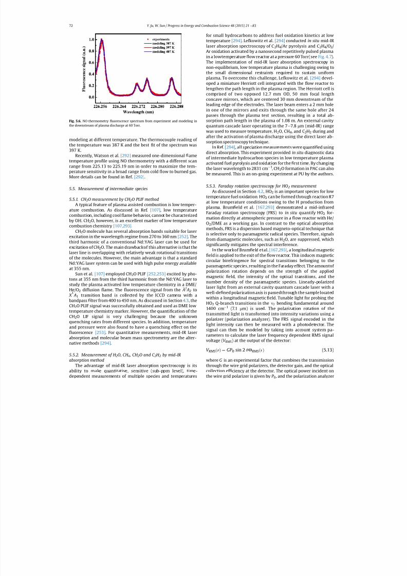
7/21/2019 Plasma Assisted Combustion Dynamics and Chemistry
http://slidepdf.com/reader/full/plasma-assisted-combustion-dynamics-and-chemistry 52/63
modeling at different temperature. The thermocouple reading of the temperature was 387 K and the best t of the spectrum was
397 K.Recently, Watson et al. [292] measured one-dimensional ametemperature pro le using NO thermometry with a different scanrange from 225.13 to 225.19 nm in order to maximize the tem-perature sensitivity in a broad range from cold ow to burned gas.More details can be found in Ref. [292] .
5.5. Measurement of intermediate species
5.5.1. CH 2O measurement by CH 2O PLIF methodA typical feature of plasma assisted combustion is low temper-
ature combustion. As discussed in Ref. [107] , low temperaturecombustion, including cool ame behavior, cannot be characterizedby OH. CH2O, however, is an excellent marker of low temperature
combustion chemistry [107,293] .CH2O molecule has several absorption bands suitable for laser
excitation in the wavelength regime from 270 to 360 nm [252] . Thethird harmonic of a conventional Nd:YAG laser can be used forexcitation of CH 2O. The main drawbackof this alternative is that thelaser line is overlapping with relatively weak rotational transitionsof the molecules. However, the main advantage is that a standardNd:YAG laser system can be used with high pulse energy availableat 355 nm.
Sun et al. [107] employed CH 2O PLIF [252,253] excited by pho-tons at 355 nm from the third harmonic from the Nd:YAG laser tostudy the plasma activated low temperature chemistry in a DME/He/O 2 diffusion ame. The uorescence signal from the
~
A1 A 2 to~
X 1 A1 transition band is collected by the ICCD camera with a
bandpass lter from 400 to 450 nm. As discussed in Section 4.3 , theCH2O PLIF signal was successfully obtained and used as DME lowtemperature chemistry marker. However, the quanti cation of theCH2O LIF signal is very challenging because the unknownquenching rates from different species. In addition, temperatureand pressure were also found to have a quenching effect on the
uorescence [253] . For quantitative measurements, mid-IR laserabsorption and molecular beam mass spectrometry are the alter-native methods [294] .
5.5.2. Measurement of H 2O, CH 4, CH 2O and C 2H 2 by mid-IRabsorption method
The advantage of mid-IR laser absorption spectroscopy is itsability to make quantitative, sensitive (sub-ppm level), time-
dependent measurements of multiple species and temperatures
for small hydrocarbons to address fuel oxidation kinetics at lowtemperature [294] . Lefkowitz et al. [294] conducted in situ mid-IR laser absorption spectroscopy of C 2H4/Ar pyrolysis and C 2H4/O2/Ar oxidation activated by a nanosecond repetitively pulsed plasmain a lowtemperature ow reactor at a pressure 60 Torr(see Fig. 4.7 ).The implementation of mid-IR laser absorption spectroscopy innon-equilibrium, low temperature plasma is challenging owing tothe small dimensional restraints required to sustain uniformplasma. To overcome this challenge, Lefkowitz et al. [294] devel-oped a miniature Herriott cell integrated with the ow reactor tolengthen the path length in the plasma region. The Herriott cell iscomprised of two opposed 12.7 mm OD, 50 mm focal lengthconcave mirrors, which are centered 30 mm downstream of theleading edge of the electrodes. The laser beam enters a 2 mm holein one of the mirrors and exits through the same hole after 24passes through the plasma test section, resulting in a total ab-sorption path length in the plasma of 1.08 m. An external cavityquantum cascade laser operating in the 7 e 7.8 mm (mid-IR) rangewas used to measure temperature, H 2O, CH4 , and C 2H2 during andafter the activation of plasma discharge using the direct laser ab-sorption spectroscopy technique.
In Ref. [294] , all speciation measurements were quanti ed usingdirect absorption. This experiment provided in situ diagnostic dataof intermediate hydrocarbon species in low temperature plasmaactivated fuel pyrolysis and oxidation for the rst time. By changingthe laser wavelength to 2831 cm 1, CH2O formation in PAC can alsobe measured. This is an on-going experiment at PU by the authors.
5.5.3. Faraday rotation spectroscopy for HO 2 measurement As discussed in Section 4.2 , HO2 is an important species for low
temperature fuel oxidation. HO 2 can be formed through reaction R7at low temperature conditions owing to the H production fromplasma. Brum eld et al. [167,293] demonstrated a mid-infraredFaraday rotation spectroscopy (FRS) to in situ quantify HO 2 for-mation directly at atmospheric pressure in a ow reactor with He/O2/DME as a working gas. In contrast to the optical absorptionmethods, FRS is a dispersion based magneto-optical technique thatis selective only to paramagnetic radical species. Therefore, signalsfrom diamagnetic molecules, such as H 2O, are suppressed, whichsigni cantly mitigates the spectral interference.
In the workof Brum eld etal. [167,293] , a longitudinal magneticeld is applied to the exit of the ow reactor. This induces magnetic
circular birefringence for spectral transitions belonging to theparamagnetic species, resulting in the Faraday effect. The amountof polarization rotation depends on the strength of the appliedmagnetic eld, the intensity of the optical transitions, and thenumber density of the paramagnetic species. Linearly-polarizedlaser light from an external cavity quantum cascade laser with awell-de ned polarization axis is passedthrough the sample locatedwithin a longitudinal magnetic eld. Tunable light for probing theHO2 Q-branch transitions in the n2 bending fundamental around1400 cm 1 (7.1 mm) is used. The polarization rotation of thetransmitted light is transformed into intensity variations using apolarizer (polarization analyzer). The FRS signal encoded in thelight intensity can then be measured with a photodetector. Thesignal can then be modeled by taking into account system pa-rameters to calculate the laser frequency dependent RMS signalvoltage ( V RMS ) at the output of the detector:
V RMS ð~
nÞ ¼ GP 0 sin 2 qQ RMS ð~
nÞ (5.13)
where G is an experimental factor that combines the transmissionthrough the wire grid polarizers, the detector gain, and the opticalcollection ef ciency at the detector. The optical power incident on
the wire grid polarizer is given by P 0 , and the polarization analyzer
Fig. 5.6. NO thermometry uorescence spectrum from experiment and modeling inthe downstream of plasma discharge at 60 Torr.
Y. Ju, W. Sun / Progress in Energy and Combustion Science 48 (2015) 21 e 8372
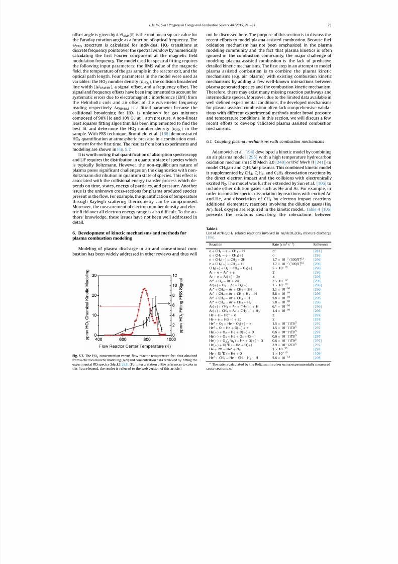
7/21/2019 Plasma Assisted Combustion Dynamics and Chemistry
http://slidepdf.com/reader/full/plasma-assisted-combustion-dynamics-and-chemistry 53/63
offset angle is given by q. Q RMS ð~
nÞ is the root mean square value forthe Faraday rotation angle as a function of optical frequency. TheQ RMS spectrum is calculated for individual HO 2 transitions atdiscrete frequency points over the spectral window by numericallycalculating the rst Fourier component at the magnetic eldmodulation frequency. The model used for spectral tting requiresthe following input parameters: the RMS value of the magnetic
eld, the temperature of the gas sample in the reactor exit, and theoptical path length. Four parameters in the model were used asvariables: the HO 2 number density ðnHO2 Þ, the collision broadenedline width ( D ~
nHWHM ), a signal offset, and a frequency offset. Thesignal and frequency offsets have been implemented to account forsystematic errors due to electromagnetic interference (EMI) fromthe Helmholtz coils and an offset of the wavemeter frequencyreading respectively. D ~
nHWHM is a tted parameter because thecollisional broadening for HO 2 is unknown for gas mixturescomposed of 90% He and 10% O 2 at 1 atm pressure. A non-linearleast squares tting algorithm has been implemented to nd thebest t and determine the HO 2 number density ðnHO2 Þ in thesample. With FRS technique, Brum eld et al. [166] demonstratedHO2 quanti cation at atmospheric pressure in a combustion envi-ronment for the rst time. The results from both experiments andmodeling are shown in Fig. 5.7.
It is worth noting that quanti cation of absorption spectroscopyand LIF requires the distribution in quantum state of species whichis typically Boltzmann. However, the non-equilibrium nature of plasma poses signi cant challenges on the diagnostics with non-Boltzmann distribution in quantum state of species. This effect isassociated with the collisional energy transfer process which de-pends on time, states, energy of particles, and pressure. Anotherissue is the unknown cross-sections for plasma produced speciespresent in the ow. For example, the quanti cation of temperaturethrough Rayleigh scattering thermometry can be compromised.Moreover, the measurement of electron number density and elec-tric eld over all electron energy range is also dif cult. To the au-thors' knowledge, these issues have not been well addressed in
detail.
6. Development of kinetic mechanisms and methods for plasma combustion modeling
Modeling of plasma discharge in air and conventional com-bustion has been widely addressed in other reviews and thus will
not be discussed here. The purpose of this section is to discuss therecent efforts to model plasma assisted combustion. Because fueloxidation mechanism has not been emphasized in the plasmamodeling community and the fact that plasma kinetics is oftenignored in the combustion community, the major challenge of modeling plasma assisted combustion is the lack of predictivedetailed kinetic mechanisms. The rst step in an attempt to modelplasma assisted combustion is to combine the plasma kineticmechanisms (e.g. air plasma) with existing combustion kineticmechanisms by adding a few well-known interactions betweenplasma generated species and the combustion kinetic mechanism.Therefore, there may exist many missing reaction pathways andintermediate species. Moreover, due to the limited data available inwell-de ned experimental conditions, the developed mechanismsfor plasma assisted combustion often lack comprehensive valida-tions with different experimental methods under broad pressureand temperature conditions. In this section, we will discuss a fewrecent efforts to develop validated plasma assisted combustionmechanisms.
6.1. Coupling plasma mechanisms with combustion mechanisms
Adamovich et al. [194] developed a kinetic model by combiningan air plasma model [295] with a high temperature hydrocarbonoxidation mechanism (GRI Mech 3.0 [240] or USC Mech II [241] ) tomodel CH 4/air and C 2H4/air plasmas. This combined kinetic modelis supplemented by CH 4, C2H4, and C 2H2 dissociation reactions bythe direct electron impact and the collisions with electronicallyexcited N 2. The model was further extended by Sun et al. [106] toinclude other dilution gases such as He and Ar. For example, inorder to consider species dissociation by reactions with excited Arand He, and dissociation of CH 4 by electron impact reactions,additional elementary reactions involving the dilution gases (He/Ar), fuel, oxygen are required in the kinetic model. Table 4 [106]presents the reactions describing the interactions between
Fig. 5.7. The HO2 concentration versus ow reactor temperature for: data obtainedfrom a chemical kinetic modeling (red) and concentration data retrieved by tting theexperimental FRS spectra (black) [293] . (For interpretation of the references to color in
this
gure legend, the reader is referred to the web version of this article.)
Table 4List of Ar/He/CH 4 related reactions involved in Ar/He/O 2/CH4 mixture discharge[106] .
Reaction Rate (cm 3 s 1) Reference
e þ CH4 ¼ e þ CH3 þ H s a [281]e þ CH4 ¼ e þ CH4(þ ) s [296]e þ CH4(þ ) ¼ CH2 þ 2H 1.7 10 7 (300/T) 0.5 [296]e þ CH4(þ ) ¼ CH3 þ H 1.7 10 7 (300/T) 0.5 [296]CH4(þ ) þ O2 ¼ CH4 þ O2(þ ) 5 10 10 [296]Ar þ e ¼ Ar* þ e S [296]Ar þ e ¼ Ar( þ ) þ 2e S [296]Ar* þ O2 ¼ Ar þ 2O 2 10 10 [296]Ar(þ ) þ O2 ¼ Ar þ O2(þ ) 1 10 10 [296]Ar* þ CH4 ¼ Ar þ CH2 þ 2H 3.3 10 10 [296]Ar* þ CH4 ¼ Ar þ CH þ H2 þ H 5.8 10 10 [296]Ar* þ CH4 ¼ Ar þ CH3 þ H 5.8 10 10 [296]Ar* þ CH4 ¼ Ar þ CH2 þ H2 5.8 10 10 [296]Ar(þ ) þ CH4 ¼ Ar þ CH3(þ ) þ H 6.5 10 10 [296]Ar(þ ) þ CH4 ¼ Ar þ CH2(þ ) þ H2 1.4 10 10 [296]He þ e ¼ He* þ e S [297]He þ e ¼ He( þ ) þ 2e S [297]He* þ O2 ¼ He þ O2(þ ) þ e 1.5 10 11T0 .5 [297]He* þ O ¼ He þ O(þ ) þ e 1.5 10 11T0 .5 [297]He( þ ) þ O2 ¼ He þ O(þ ) þ O 0.6 10 11T0 .5 [297]He( þ ) þ O3 ¼ He þ O2 þ O(þ ) 0.6 10 11T0 .5 [297]He( þ ) þ O2(a
1Dg) ¼ He þ O(þ ) þ O 0.6 10 11T0 .5 [297]He( þ ) þ O(1D) ¼ He þ O(þ ) 2.9 10 12T0 .5 [297]He þ 2O ¼ He* þ O2 1 10 33 [297]He þ O(1D) ¼ He þ O 1 10 10 [109]He* þ CH4 ¼ He þ CH þ H2 þ H 5.6 10 13 [298]a The rate is calculated by the Boltzmann solver using experimentally measured
cross-sections, s .
Y. Ju, W. Sun / Progress in Energy and Combustion Science 48 (2015) 21 e 83 73

7/21/2019 Plasma Assisted Combustion Dynamics and Chemistry
http://slidepdf.com/reader/full/plasma-assisted-combustion-dynamics-and-chemistry 54/63
plasma kinetics and fuel oxidation kinetics. The kinetic models alsoincorporated chemical reactions of electronically excited species,electron-ion recombination reactions, ion e ion neutralization pro-cesses, ion e molecule collisional energy transfer reactions, andelectron attachment and detachment processes.
The rate coef cients of electron impact ionization, dissociation,and electronic excitation as well as the electron energy distributionfunction (EEDF) are normally calculated by using a Boltzmannequation solver (such as BOLSIG [299] ) with the input of electronimpact cross-sections. Similar plasma assisted combustion kineticmodels containing H 2, CH4 to C5H12 were developed by Aleksan-drov et al. [246] and Starikovskaia et al. [239] . Since no reliablecross-section data are available for large hydrocarbons such asC3H8, C4H10 and C 5H12 , the authors assumed that these cross-sections are similar to those for C 2H6. Among these kineticmodels, the H 2/air plasma model [239] is a detailed state-to-statekinetic model including 750 chemical and 8700 vibrational en-ergy exchange processes with 254 species. To the authors' knowl-edge, the most updated electron impact cross section data havebeen documented, respectively, in references for O 2 [300] , N2 [301] ,H2 [302] , CO [303] , CO2 [304] , H2O [305] , and simple hydrocarbonmolecules (CH 4, C2H6, C2H4, C2H2 , C3H8, C3H6 [306] , and n-C 4H10
[307] (only for ionization).Uddi et al. [160] showed that the kinetic model predictions
using the model developed by Adamovich et al. [194] were in goodoverall agreement with the experimental data for TALIF O mea-surements. However, the overall agreement might be partly due tothe “ lucky or magic choice ” of the E/N ratio. In addition, for the fueloxidation products, different combustion kinetic models had verydifferent predictions and the results differ by almost one order of magnitude as shown in Fig. 6.1. Since the same set of plasma re-actions and rates were used in both cases, the difference betweenthe two kinetic models was from the difference between the re-actions and rates used by GRI Mech 3.0 [240] and USC Mech II [241] .
Note that both GRI Mech and USC Mech were developed for thepurpose of high temperature combustion. As pointed out by Sun
et al. [106] , fuel oxidation kinetic mechanisms have rarely beenvalidated at low temperature conditions. Figs. 4.6 and 4.7 showclearly that there exist many low temperature fuel oxidationpathways which are missing in GRI and USC Mech. In addition, thepredicted low temperature species concentrations (H 2O and CH 4)
differ by even one order. Therefore, there are large uncertainties inexisting plasma combustion mechanisms at low temperature andhigh pressure conditions, especially for large molecule liquid fuels.
6.2. Recent developments of plasma mechanisms
To extend the validity of combustion modeling to high pressureand lower temperature conditions, a collaborative effort to developa comprehensive high pressure plasma combustion mechanism(HP-Mech/plasma) for small hydrocarbon including (H 2/H 2O2/O3/CO/CH2O/CH3OH) has been carried out by the team members of theAFOSR multi-university research initiative on plasma assistedcombustion (MURI-plasma) at Penn State, Princeton, and OhioState. The approach is to take the advantage of the recent devel-opment of a high pressure hydrogen mechanism [308] , formalde-hyde and methanol mechanism [309] , formaldehyde and acetylenemechanism [242] , O3 decomposition rate [310] , and NO x mecha-nism [311] . Reactions of O( 1D) with fuels/N 2/O2/CO/CO2/H 2O/CH 2Oand O 2 singlet with fuels/H/OH/CH 3/H 2/CH4 are updated using thebest estimates of the energy barriers and rate constants. Lowtemperature fuel oxidation pathways including RO 2 and aldehydeformation are also added using similarity rules [312,313] . Fig. 6.2and Fig. 6.3 show the preliminary validation of the HP-Mech/plasma for H 2 and CO mixtures with NO x addition from low tohigh pressures [314] . The results showthatthe new mechanism canwell reproduce the experimental data in the variable pressure owreactor [209] . Fig. 6.3 also shows the comparison of predicted amespeeds of O 3 addition in methane/air mixture. It is seen that thenew model has better agreement with the experimental data thanthe previous model. The current HP-Mech/plasma is still in a pre-liminary version. Comprehensive validations and improvement inthe future are needed.
In recent years, another great effort has been made on thedevelopment of the kinetic mechanisms of excited molecules forplasma assisted combustion. Among different electronically excitedmolecules, singlet O 2(a
1Dg) has drawn signi cant attention. The
O2(a 1Dg) molecule is metastable. Its radiation lifetime (withoutcollisional quenching) is about 65 min, and the collisional lifetimein a CH4/air mixture at 1 atm is 4.2 10 2 s [315] . The long lifetimeand the chemical potential of O 2(a
1Dg) to intensify the chainbranching reactions such as H þ O2(a
1Dg) / OH þ O make it animportant target for the study of plasma assisted combustion.O2(a
1Dg) related chemistry has been studied for a long time, but islimited to room temperature and with small molecules. Here, onlythe recent progress of O 2(a
1Dg) related to plasma assisted com-bustion will be reviewed.
Starik et al. [315] developed a kinetic mechanism containing aO2(a
1Dg) sub-mechanism and investigated the effect of the pres-ence of O 2(a
1Dg) in a CH 4/air mixture on the laminar ame speeds.The mechanism includes three major reaction channels: (1) the
quenching of O 2(a1Dg): O 2(a
1Dg) þ M ¼ O2( X
3S g ) þ M,inwhich M is
any molecule or atom in the mixture and O 2( X 3S g ) denotes theground state of oxygen; (2) the dissociation of O 2(a
1Dg):O2(a
1Dg) þ M ¼ 2O þ M; (3) formation of O 2(b1S g
þ ) molecules:O2(a
1Dg) þ O2 ¼ O2(b1S g
þ ) þ O2 as well as chemical reactionsinvolving O 2(b
1S gþ ) molecules. The reaction rateconstants involving
excited O 2 were either taken from experimental measurements orcalculatedby the bond-energy-bond-order method. The model wasthen used to calculate amespeeds forCH 4/air mixtures at differentequivalence ratios and O 2(a
1Dg) concentrations. Fig. 6.4 shows theresults of the calculated ame speeds (U n in the gure) withO2(a
1Dg) mole fraction at 0, 0.05 and 0.1 of total O 2 concentration atincoming ow temperature T o ¼ 300 K and 450 K.
It can be seen that an increase in the temperature and in the
concentration of O 2(a1
Dg) molecules leads to an increase in the
Fig. 6.1. Fuel oxidation product mole fractions after a single high-voltage pulse inC2H4/air at P ¼ 60 Torr and F ¼ 0.5. solid lines, GRI Mech 3.0; dotted lines, USC Mech II
[160] .
Y. Ju, W. Sun / Progress in Energy and Combustion Science 48 (2015) 21 e 8374
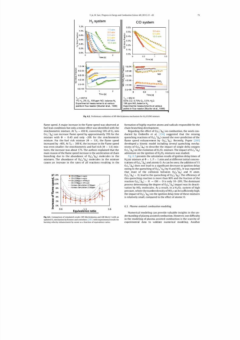
7/21/2019 Plasma Assisted Combustion Dynamics and Chemistry
http://slidepdf.com/reader/full/plasma-assisted-combustion-dynamics-and-chemistry 55/63
ame speed. A major increase in the ame speed was observed atfuel lean conditions but only a minor effect was identi ed with thestoichiometric mixture. At T 0 ¼ 450 K, converting 10% of O 2 into
O2(a 1Dg) can increase ame speed by approximately 70% for themixture with F ¼ 0.45 and only ~20% for the stoichiometricmixture. For the fuel rich mixture ( F ¼ 1.9), the ame speedincreased by ~40%. At T 0 ¼ 300 K, the increase in the ame speedwas even smaller: for stoichiometric and fuel rich ( F ¼ 1.6) mix-tures, the increase was about 17%. The authors explained that themain reason of the ame speed increase is the acceleration of chainbranching due to the abundance of O 2(a
1Dg) molecules in themixtures. The abundance of O 2(a
1Dg) molecules in the mixturecauses an increase in the rates of all reactions resulting in the
formation of highly reactive atoms and radicals responsible for thechain branching development.
Regarding the effect of O 2(a1Dg) on combustion, the work con-
ducted by Ombrello et al. [156] suggested that the missingquenching reactions of O 2(a
1Dg) caused the over-prediction of theame speed enhancement by O 2(a
1Dg). Recently, Popov [260]developed a kinetic model including several quenching mecha-nisms of O 2(a
1Dg) to describe the impact of single delta oxygenO2(a
1Dg) on the evolution of H 2/O2 mixture. The impact of O 2(a1Dg)
admixture on the ignition of H 2/O2 mixtures was studied.Fig. 6.5 presents the calculation results of ignition delay times of
H2/air mixture at F ¼ 1, P ¼ 1 atm and at different initial concen-trations of O 2(a
1Dg) and atomic O. As can be seen, the addition of 1%O2(a
1Dg) does not lead to a signi cant decrease in ignition delayowing to the quenching of O 2(a
1Dg) by H and HO 2. It was reportedthat most of the collisions between O 2(a
1Dg) and H atom,O2(a
1Dg) þ H, lead to the quenching of O 2(a1Dg). The ef ciency of
this quenching reaction is more than 80% and the fraction of thereaction O 2(a
1Dg) þ H / OH þ O is only 10 e 20%. The dominantprocess determining the degree of O 2(a
1Dg) impact was its deacti-vation by HO 2 molecules. As a result, in a H 2/O2 system of highpressure, where the numberdensity of HO 2 can besuf ciently high,the impact of O 2(a
1Dg) on the ignition delay time of these mixturesis relatively small, compared to the effect of atomic O.
6.3. Plasma assisted combustion modeling
Numerical modeling can provide valuable insights in the un-derstanding of plasma assisted combustion. However, one dif cultyin the modeling of plasma assisted combustion is the scarcity of
experimental data to validate numerical modeling. Another
Fig. 6.3. Comparison of simulated results (HP-Mech/plasma and GRI Mech 3 with anupdated O 3 mechanism by Konnov and coworkers [240] ) with experimental results for
burning velocity enhancement by ozone as a function of equivalence ratios.
Fig. 6.2. Preliminary validation of HP-Mech/plasma mechanism for H 2/CO/NO mixture.
Y. Ju, W. Sun / Progress in Energy and Combustion Science 48 (2015) 21 e 83 75
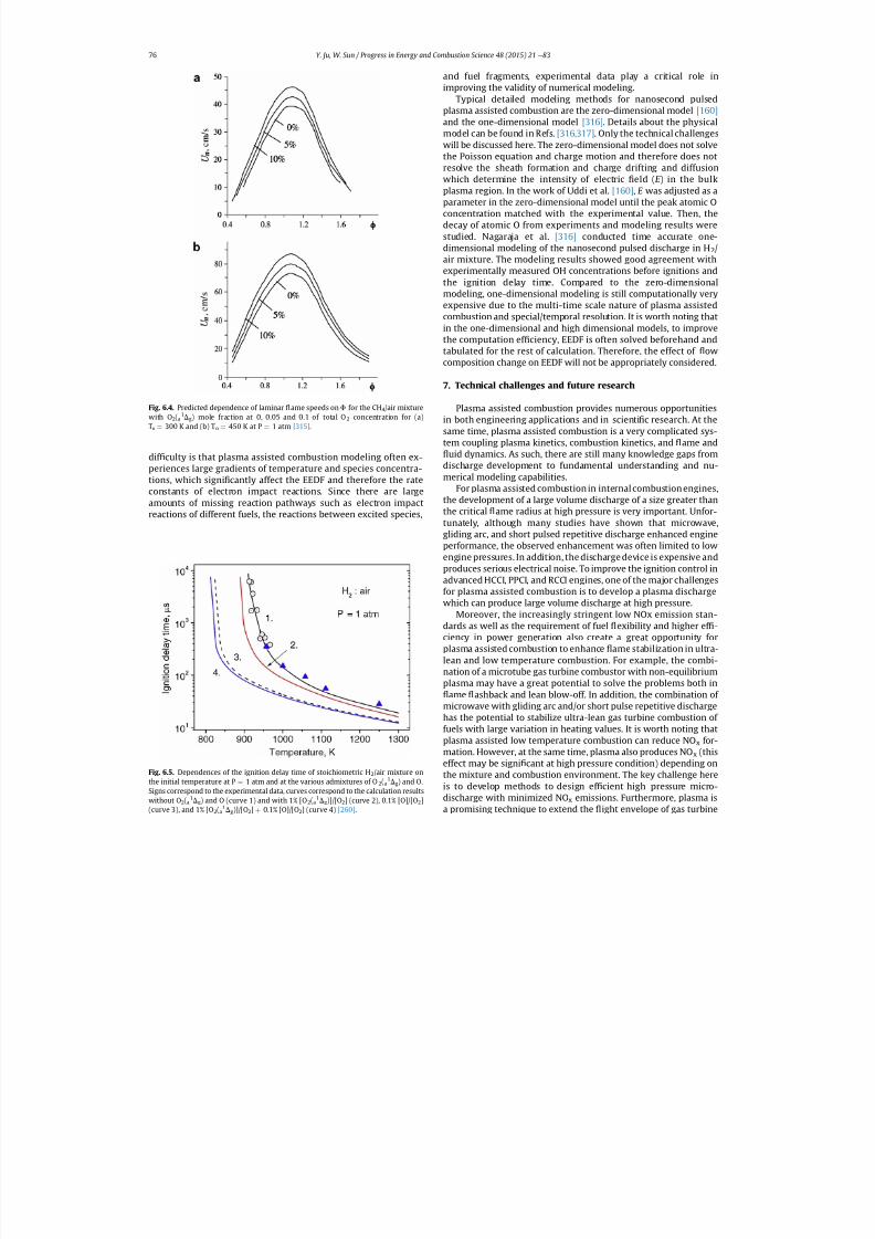
7/21/2019 Plasma Assisted Combustion Dynamics and Chemistry
http://slidepdf.com/reader/full/plasma-assisted-combustion-dynamics-and-chemistry 56/63
dif culty is that plasma assisted combustion modeling often ex-periences large gradients of temperature and species concentra-tions, which signi cantly affect the EEDF and therefore the rateconstants of electron impact reactions. Since there are largeamounts of missing reaction pathways such as electron impactreactions of different fuels, the reactions between excited species,
and fuel fragments, experimental data play a critical role inimproving the validity of numerical modeling.
Typical detailed modeling methods for nanosecond pulsedplasma assisted combustion are the zero-dimensional model [160]and the one-dimensional model [316] . Details about the physicalmodel can be found in Refs. [316,317] . Only the technical challengeswill be discussed here. The zero-dimensional model does not solvethe Poisson equation and charge motion and therefore does notresolve the sheath formation and charge drifting and diffusionwhich determine the intensity of electric eld ( E ) in the bulkplasma region. In the work of Uddi et al. [160] , E was adjusted as aparameter in the zero-dimensional model until the peak atomic Oconcentration matched with the experimental value. Then, thedecay of atomic O from experiments and modeling results werestudied. Nagaraja et al. [316] conducted time accurate one-dimensional modeling of the nanosecond pulsed discharge in H 2/air mixture. The modeling results showed good agreement withexperimentally measured OH concentrations before ignitions andthe ignition delay time. Compared to the zero-dimensionalmodeling, one-dimensional modeling is still computationally veryexpensive due to the multi-time scale nature of plasma assistedcombustion and special/temporal resolution. It is worth noting thatin the one-dimensional and high dimensional models, to improvethe computation ef ciency, EEDF is often solved beforehand andtabulated for the rest of calculation. Therefore, the effect of owcomposition change on EEDF will not be appropriately considered.
7. Technical challenges and future research
Plasma assisted combustion provides numerous opportunitiesin both engineering applications and in scienti c research. At thesame time, plasma assisted combustion is a very complicated sys-tem coupling plasma kinetics, combustion kinetics, and ame and
uid dynamics. As such, there are still many knowledge gaps fromdischarge development to fundamental understanding and nu-merical modeling capabilities.
For plasma assisted combustion in internal combustion engines,the development of a large volume discharge of a size greater thanthe critical ame radius at high pressure is very important. Unfor-tunately, although many studies have shown that microwave,gliding arc, and short pulsed repetitive discharge enhanced engineperformance, the observed enhancement was often limited to lowengine pressures. In addition, the discharge device is expensive andproduces serious electrical noise. To improve the ignition control inadvanced HCCI, PPCI, and RCCI engines, one of the major challengesfor plasma assisted combustion is to develop a plasma dischargewhich can produce large volume discharge at high pressure.
Moreover, the increasingly stringent low NOx emission stan-dards as well as the requirement of fuel exibility and higher ef -ciency in power generation also create a great opportunity for
plasma assisted combustion to enhance ame stabilization in ultra-lean and low temperature combustion. For example, the combi-nation of a microtube gas turbine combustor with non-equilibriumplasma may have a great potential to solve the problems both in
ame ashback and lean blow-off. In addition, the combination of microwave with gliding arc and/or short pulse repetitive dischargehas the potential to stabilize ultra-lean gas turbine combustion of fuels with large variation in heating values. It is worth noting thatplasma assisted low temperature combustion can reduce NO x for-mation. However, at the same time, plasma also produces NO x (thiseffect may be signi cant at high pressure condition) depending onthe mixture and combustion environment. The key challenge hereis to develop methods to design ef cient high pressure micro-discharge with minimized NO x emissions. Furthermore, plasma is
a promising technique to extend the
ight envelope of gas turbine
Fig. 6.4. Predicted dependence of laminar ame speeds on F for the CH 4/air mixturewith O 2(a
1Dg) mole fraction at 0, 0.05 and 0.1 of total O 2 concentration for (a)To ¼ 300 K and (b) T o ¼ 450 K at P ¼ 1 atm [315] .
Fig. 6.5. Dependences of the ignition delay time of stoichiometric H 2/air mixture onthe initial temperature at P ¼ 1 atm and at the various admixtures of O 2(a
1Dg) and O.Signs correspond to the experimental data, curves correspond to the calculation resultswithout O 2(a
1Dg) and O (curve 1) and with 1% [O 2(a1Dg)]/[O2] (curve 2), 0.1% [O]/[O 2]
(curve 3), and 1% [O 2(a
1
Dg)]/[O2] þ
0.1% [O]/[O2] (curve 4) [260] .
Y. Ju, W. Sun / Progress in Energy and Combustion Science 48 (2015) 21 e 8376
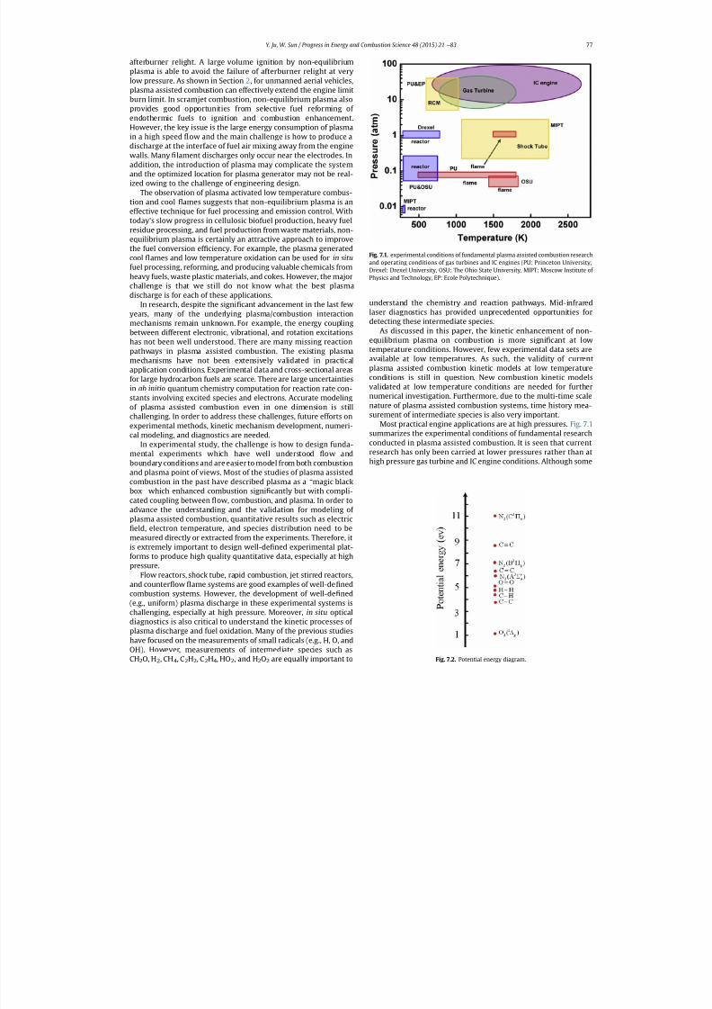
7/21/2019 Plasma Assisted Combustion Dynamics and Chemistry
http://slidepdf.com/reader/full/plasma-assisted-combustion-dynamics-and-chemistry 57/63
afterburner relight. A large volume ignition by non-equilibriumplasma is able to avoid the failure of afterburner relight at verylow pressure. As shown in Section 2, for unmanned aerial vehicles,plasma assisted combustion can effectively extend the engine limitburn limit. In scramjet combustion, non-equilibrium plasma alsoprovides good opportunities from selective fuel reforming of endothermic fuels to ignition and combustion enhancement.However, the key issue is the large energy consumption of plasmain a high speed ow and the main challenge is how to produce adischarge at the interface of fuel air mixing away from the enginewalls. Many lament discharges only occur near the electrodes. Inaddition, the introduction of plasma may complicate the systemand the optimized location for plasma generator may not be real-ized owing to the challenge of engineering design.
The observation of plasma activated low temperature combus-tion and cool ames suggests that non-equilibrium plasma is aneffective technique for fuel processing and emission control. Withtoday's slow progress in cellulosic biofuel production, heavy fuelresidue processing, and fuel production from waste materials, non-equilibrium plasma is certainly an attractive approach to improvethe fuel conversion ef ciency. For example, the plasma generatedcool ames and low temperature oxidation can be used for in situfuel processing, reforming, and producing valuable chemicals fromheavy fuels, waste plastic materials, and cokes. However, the majorchallenge is that we still do not know what the best plasmadischarge is for each of these applications.
In research, despite the signi cant advancement in the last fewyears, many of the underlying plasma/combustion interactionmechanisms remain unknown. For example, the energy couplingbetween different electronic, vibrational, and rotation excitationshas not been well understood. There are many missing reactionpathways in plasma assisted combustion. The existing plasmamechanisms have not been extensively validated in practicalapplication conditions. Experimental data and cross-sectional areasfor large hydrocarbon fuels are scarce. There are large uncertaintiesin ab initio quantum chemistry computation for reaction rate con-
stants involving excited species and electrons. Accurate modelingof plasma assisted combustion even in one dimension is stillchallenging. In order to address these challenges, future efforts onexperimental methods, kinetic mechanism development, numeri-cal modeling, and diagnostics are needed.
In experimental study, the challenge is how to design funda-mental experiments which have well understood ow andboundary conditions and are easier to model from both combustionand plasma point of views. Most of the studies of plasma assistedcombustion in the past have described plasma as a “ magic blackbox ” which enhanced combustion signi cantly but with compli-cated coupling between ow, combustion, and plasma. In order toadvance the understanding and the validation for modeling of plasma assisted combustion, quantitative results such as electric
eld, electron temperature, and species distribution need to bemeasured directly or extracted from the experiments. Therefore, itis extremely important to design well-de ned experimental plat-forms to produce high quality quantitative data, especially at highpressure.
Flow reactors, shock tube, rapid combustion, jet stirred reactors,and counter ow ame systems are good examples of well-de nedcombustion systems. However, the development of well-de ned(e.g., uniform) plasma discharge in these experimental systems ischallenging, especially at high pressure. Moreover, in situ opticaldiagnostics is also critical to understand the kinetic processes of plasma discharge and fuel oxidation. Many of the previous studieshave focused on the measurements of small radicals (e.g., H, O, andOH). However, measurements of intermediate species such as
CH2O, H2 , CH4, C2H2, C2H4, HO2, and H 2O2 are equally important to
understand the chemistry and reaction pathways. Mid-infraredlaser diagnostics has provided unprecedented opportunities fordetecting these intermediate species.
As discussed in this paper, the kinetic enhancement of non-equilibrium plasma on combustion is more signi cant at lowtemperature conditions. However, few experimental data sets areavailable at low temperatures. As such, the validity of currentplasma assisted combustion kinetic models at low temperatureconditions is still in question. New combustion kinetic modelsvalidated at low temperature conditions are needed for further
numerical investigation. Furthermore, due to the multi-time scalenature of plasma assisted combustion systems, time history mea-surement of intermediate species is also very important.
Most practical engine applications are at high pressures. Fig. 7.1summarizes the experimental conditions of fundamental researchconducted in plasma assisted combustion. It is seen that currentresearch has only been carried at lower pressures rather than athigh pressure gas turbine and IC engine conditions. Although some
Fig. 7.1. experimental conditions of fundamental plasma assisted combustion research
and operating conditions of gas turbines and IC engines (PU: Princeton University,Drexel: Drexel University, OSU: The Ohio State University, MIPT: Moscow Institute of Physics and Technology, EP: Ecole Polytechnique).
Fig. 7.2. Potential energy diagram.
Y. Ju, W. Sun / Progress in Energy and Combustion Science 48 (2015) 21 e 83 77
7/21/2019 Plasma Assisted Combustion Dynamics and Chemistry
http://slidepdf.com/reader/full/plasma-assisted-combustion-dynamics-and-chemistry 58/63
rapid compression machine studies have extended the experimentto higher pressure, the discharge is not uniform and it is dif cult tounderstand the fundamental kinetics. Unfortunately, high pressurecauses thermal instability and local collisional thermalization of plasma. Therefore, developing experimental methods to generatestable, uniform non-equilibrium plasma under practical combustorpressure conditions is a challenging question for fundamentalresearch. This challenge is not only open to the combustion societybut also to the plasma research society.
Understanding the energy transfer between different excitedenergy modes is dif cult. Due to the high excitation energy, plasmacan introduce many new reaction pathways between excited spe-cies and through the collisions of excited species with neutralmolecules. In N 2, He, and Ar plasma systems, the electronic exci-tation energies are very high (above 5 eV for N 2, and 10 eV for Arand He). As shown in Fig. 7.2, the excitation energy is much higherthan the chemical bond energy of most hydrocarbon fuels. Hence,the excited species contain a signi cant amount of energy, and arecapable of dissociating a fuel molecule in a single collision. Thisphenomenon can lead to drastic changes in the transport andchemical properties of the combustible mixture. Energy transferinvolving vibrationally excited species such as N 2(v), O2(v) andHO2(v) is even more complicated. Unfortunately, few diagnostics of electronically and vibrationally excited molecules have been made.The studies of new reaction pathways involving energy transfer of excited species in plasma assisted combustion require advanceddiagnostic techniques to quantitatively detect these species in situ .
Modeling of plasma assisted combustion is also dif cult. Plasmadischarge is a multi-physical, multi-scale, and non-equilibriumprocess. The characteristic time of plasma kinetics ranges fromsub-nanoseconds to milliseconds, which is vastly different from thecharacteristic time of combustion kinetics. The non-equilibriumand multi-time scale nature make the numerical modeling of plasma assisted combustion extremely challenging. For example,appropriate modeling of unsteady, multidimensional short pulsedischarge including the sheath effect is still dif cult. Most of the
existing methods are based on the estimated E/N distribution andthe non-equilibrium Boltzmann solver without considering thesheath effect and the coupling between electric eld and chargemotion. An ef cient and validated plasma modeling approach isneeded.
8. Conclusion
Signi cant advancements in plasma assisted combustion havebeen made in both practical applications and fundamental under-standing. New observations of plasma assisted ignition enhance-ment, ame speed enhancement, ultra-lean combustion, cool
ames, ameless combustion, emission reduction, and low tem-perature fuel reforming are reported in internal combustion en-
gines, gas turbines, turbulent ames, high speed propulsionsystems, and fuel processing. Several signi cant advances in un-derstanding of non-thermal and thermal effects, kinetic pathwaysof atomic oxygen production, diagnostics of electronically andvibrationally excited species, plasma combustion kinetics of sub-explosion limit ignition, plasma assisted low temperature com-bustion, transitions of the classical ignition S -curve, dynamics of the minimum ignition energy, and the transport effect by non-equilibrium plasma discharge, have been made. These ndingsand advances create many new opportunities in the developmentof ef cient plasma discharges for practical applications and infuture research. However, there are still large knowledge gaps inboth discharge development and fundamental understanding andmodeling capabilities. In engineering applications, development of
ef cient plasma discharge for large volume ignition at high
pressure is the key to extend plasma assisted combustion in en-gines. In research, understanding of the energy coupling betweendifferent electronic, vibrational, and rotation excitations remainchallenging. The existing plasma mechanisms have not beenextensively validated in practical application conditions. There aremany missing reaction pathways in plasma assisted combustion.Experimental data and cross-section areas for large hydrocarbonfuels are scarce. Accurate modeling of plasma assisted combustioneven in one-dimensional is still dif cult due to the multi-timescaleand non-equilibrium nature of plasma. In order to address thesechallenges, future efforts on experiments, kinetic mechanism, nu-merical modeling, and diagnostics are needed.
Acknowledgment
This work was supported by AFOSR MURI research grantFA9550-07-1-0136 and AFOSR grant FA9550-13-1-0119 from theAir Force Of ce of Scienti c Research, with Drs. Julian Tishkoff andChiping Li as the technical monitors. This work is also prepared inmemory of Prof. Kenichi Takita, a pioneer of plasma torch appli-cation in supersonic combustors.
References
[1] Chu S, Majumdar A. Opportunities and challenges for a sustainable energyfuture. Nature 2012;488:294 e 303 .
[2] Christensen M, Hultqvist A, Johansson B. Demonstrating the multi-fuelcapability of a homogeneous charge compression ignition engine with var-iable compression ratio. SAE Trans 1999;108:2099 e 113 .
[3] Dec J. Advanced compression e ignition engines e understanding the in-cylinder processes. Proc Combust Inst 2010;32:2727 e 42 .
[4] Lu X, Han D, Huang Z. Fuel design and management for the control of advanced compression-ignition combustion modes. Prog Energy CombustSci 2011;37:741 e 83 .
[5] Manente V, Johansson B, Cannella W. Gasoline partially premixed combus-tion, the future of internal combustion engines? Int J Engine Res 2011;12:194 e 208 .
[6] Reitz RD. Directions in internal combustion engine research. Combust Flame
2013;160:1 e 8.[7] Curran HJ, Gaffuri P, Pitz WJ, Westbrook CK. A comprehensive modeling
study of iso-octane oxidation. Combust Flame 2002;129:253 e 80 .[8] Mongia HC, Lafayette W, On continuous NOx reduction of aero-propulsion
engines. In: 48th AIAA aerospace sciences meeting including the newHorizons forum and aerospace exposition, Orlando, Florida: AIAA-2010-1329.
[9] McManus K. Low-emissions gas turbine combustion: design trends andchallenges. In: Fall meeting of the eastern states section of the combustioninstitute; 2013. Clemson, SC .
[10] Mao C. Experimental investigation of a multiplex fuel injector module. In:42nd aerospace sciences meeting including the new horizons forum andaerospace exposition, 5 e 8 January 2004, Reno, Nevada; 2004. AIAA-2004-135 .
[11] Hsu K, Goss LP. Characteristics of a trapped-vortex combustor introduction. J Propuls Power 1998;14:57 e 69 .
[12] Schwer D, Kailasanath K. Numerical investigation of the physics of rotating-detonation-engines. Proc Combust Inst 2011;33:2195 e 202 .
[13] Moorthy JVS, Rajinikanth B, Charyulu BVN, Amba Prasad Rao G. Scramjetcombustor development: a review. J Aerosp Eng Technol 2012;2:28 e 41 .
[14] Yu G, Fan XJ. Supersonic combustion and hypersonic propulsion. Adv Mech2013;43:449 e 71 .
[15] Jiang Z, Yu H. Experiments and development of long-test-duration hyper-velocity detonation-driven shock tunnel (LHDst). In: 52nd AIAA aerospacesciences meeting including the new horizons forum and aerospace exposi-tion, National Harbor, Maryland; 2014. AIAA-2014-1012 .
[16] http://www.netl.doe.gov/research/coal/energy-systems/gasi cation/gasi pedia/hydrogen-turbines .
[17] Santner J, Dryer FL, Ju Y. The effects of water dilution on hydrogen, syngas,and ethylene ames at elevated pressure. Proc Combust Inst 2013;34:719 e 26 .
[18] Katsuki M, Hasegawa T. The science and technology of combustion in highlypreheated air. Symp Int Combust 1998;27:3135 e 46 .
[19] Cavaliere A, de Joannon M. Mild combustion. Prog Energy Combust Sci2004;30:329 e 66 .
[20] Buhre BJP, Elliott LK, Sheng CD, Gupta RP, Wall TF. Oxy-fuel combustiontechnology for coal- red power generation. Proc Combust Inst 2005;31:
283e
307 .
Y. Ju, W. Sun / Progress in Energy and Combustion Science 48 (2015) 21 e 8378
7/21/2019 Plasma Assisted Combustion Dynamics and Chemistry
http://slidepdf.com/reader/full/plasma-assisted-combustion-dynamics-and-chemistry 59/63
[21] Larfeldt J. An industrial perspective on plasma assisted combustion. Lund,Sweden: Lecture at Lund University; 2014 .
[22] Hu Q, Sommerfeld M, Jarvis E, Ghirardi M, Posewitz M, Seibert M, et al.Microalgal triacylglycerols as feedstocks for biofuel production: perspectivesand advances. Plant J 2008;54:621 e 39 .
[23] Kohse-H€
oinghaus K, Osswald P, Cool T, Kasper T, Hansen N, Qi F, et al. Biofuelcombustion chemistry: from ethanol to biodiesel. Angew Chem Int Ed2010;49:3572 e 97 .
[24] Dooley S, Won SH, Chaos M, Heyne J, Ju Y, Dryer FL, et al. A jet fuel surrogateformulated by real fuel properties. Combust Flame 2010;157:2333 e 9.
[25] Bessee GB, Hutzler SA, Wilson GR. Propulsion and power rapid responseresearch and development (R & D) support: analysis of synthetic aviationfuels. San Antonio TX: Southwest Research Inst.; 2011 .
[26] Blakey S, Rye L, Wilson CW. Aviation gas turbine alternative fuels: a review.Proc Combust Inst 2011;33:2863 e 85 .
[27] Dale BE, Kim S. Biomass re ning global Impact e the biobased economy of the21st century. Biore neries-industrial processes and products: status quo andfuture directions. 2006. p. 41 e 66 .
[28] Ju Y. Recent progress and challenges in fundamental combustion research.Adv Mech 2014;44:201402 .
[29] Westbrook CK. Biofuels combustion. Annu. Rev Phys Chem 2013;64:201 e 19 .[30] Won SH, Dooley S, Veloo PS, Wang H, Oehlschlaeger MA, Dryer FL, et al. The
combustion properties of 2,6,10-trimethyl dodecane and a chemical func-tional group analysis. Combust Flame 2014;161:826 e 34 .
[31] Dievart P, Won SH, Gong J, Dooley S, Ju Y. A comparative study of thechemical kinetic characteristics of small methyl esters in diffusion ameextinction. Proc Combust Inst 2012;34:821 e 9.
[32] Harper MR, Van Geem KM, Pyl SP, Marin GB, Green WH. Comprehensivereaction mechanism for n-butanol pyrolysis and combustion. Combust Flame2011;158:16 e 41 .
[33] Rasi S, Veijanen A, Rintala J. Trace compounds of biogas from different biogasproduction plants. Energy 2007;32:1375 e 80 .
[34] Besenbacher F, Chorkendorff I, Clausen BS, Hammer B, Molenbroek AM,Nørskov JK, et al. Design of a surface alloy catalyst for steam reforming.Science 1998;279:1913 e 5.
[35] DoE. Report of the basic energy sciences workshop on basic research needsfor clean and ef cient combustion of 21st century transportation fuels. 2006 .
[36] Starikovskiy A, Aleksandrov N. Plasma assisted ignition and combustion.Prog Energy Combust Sci 2013;39:61 e 110 .
[37] Starikovskaia SM. Plasma assisted ignition and combustion. J Phys D ApplPhys 2006;39:R265 e 99 .
[38] Ombrello T, Qin X, Ju Y, Gutsol A, Fridman A, Carter C. Combustionenhancement via stabilized piecewise. AIAA J 2006;44:142 e 50 .
[39] Lou G, Bao A, Nishihara M, Keshav S, Utkin YG, Rich JW, et al. Ignition of premixed hydrocarbon e air ows by repetitively pulsed, nanosecond pulseduration plasma. Proc Combust Inst 2007;31:3327 e 34 .
[40] Kim W, Godfrey M, Cappelli M. The role of in situ reforming in plasma
enhanced ultra lean premixed methane/air ames. Combust Flame2010;157:374 e 83 .[41] Takita K, Uemoto T, Sato T, Ju Y, Masuya G, Ohwaki K. Ignition characteristics
of plasma torch for hydrogen jet in an airstream. J Propuls Power 2000;162:227 e 33 .
[42] Leonov SB, Yarantsev DA, Napartovich AP, Kochetov IV. Plasma-assistedcombustion of gaseous fuel in supersonic duct. IEEE Trans Plasma Sci2006;34:2514 e 25 .
[43] Sun W, Uddi M, Ombrello T, Won SH, Carter C, Ju Y. Effects of non-equilibrium plasma discharge on counter ow diffusion ame extinction.Proc Combust Inst 2011;33:3211 e 8.
[44] Kimura I, Aoki H, Kato M. The use of a plasma jet for ame stabilization andpromotion of combustion in supersonic air ows. Combust Flame 1981;42:297 e 305 .
[45] Barbi E, Mahan JR, O ’ brien WF, Wagner TC. Operating characteristics of ahydrogen-argon plasma torch for supersonic combustion applications. J Propuls Power 1989;5:129 e 33 .
[46] Takita K. Ignition and ame-holding by oxygen, nitrogen and argon plasmatorches in supersonic air ow. Combust Flame 2002;128:301 e 13 .
[47] Takita K, Abe N, Masuya G, Ju Y. Ignition enhancement by addition of NO andNO2 from a N 2/O2 plasma torch in a supersonic ow. Proc Combust Inst2007;31:2489 e 96 .
[48] Kobayashi K, Tomioka S, Mitani T. Supersonic ow ignition by plasma torchand H 2/O2 torch. Journal of propulsion and power. J Propuls Power 2004;20:294 e 301 .
[49] Wagner TC, O ’ brien WF, Northam GB, Eggers JM. Plasma torch igniter forscramjets. J Propuls Power 1989;5:548 e 54 .
[50] Jacobsen LS, Carter CD, Baurle RA, Jackson TA, Williams S, Bivolaru D, et al.Plasma-assisted ignition in scramjets. J Propuls Power 2008;24:641 e 54 .
[51] Leonov SB, Yarantsev DA. Plasma-induced ignition and plasma-assistedcombustion in high-speed ow. Plasma Sources Sci Technol 2007;16:132 e 8.
[52] Esakov I, Grachev L, Khodataev K, Van Wie D. Experiments on propaneignition in high-speed air ow using a deeply under critical microwavedischarge. In: 42nd AIAA aerospace sciences meeting including the newhorizons forum and aerospace exposition, Reno, Nevada; 2004. AIAA-2004-0840 .
[53] Williams S, Popovic S, Vuskovic L, Carter C, Jacobson L, Kuo S, et al. Modeland igniter development for plasma assisted combustion. No. AFRL-VS-HA-
TR-2004-1132. Air Force Research Lab Hanscom AFB MA Space VehiclesDirectorate; 2004 .
[54] Klimov A, Bityurin V, Kuznetsov A, Tolkunov B, Vystavkin N, Vasiliev M.External and internal plasma-assisted combustion. In: 42nd AIAA aerospacesciences meeting including the new horizons forum and aerospace exposi-tion, Reno, Nevada; 2004. AIAA-2004-1014 .
[55] Shibkov VM, Chernikov AV, Ershov AP, Konstantinovski RS, Shibkova LV,Zlobin VV. propane e butane e air mixture ignition and combustion in theaerodynamic channel with the stagnant zone. In: 42nd AIAA aerospace sci-ences meeting including the new horizons forum and aerospace exposition,
Reno, Nevada; 2004. AIAA-2004-0838 .[56] Do H, Im S, Cappelli M, Mungal MG. Plasma assisted ame ignition of su-
personic ows over a at wall. Combust Flame 2010;157:2298 e 305 .[57] Kailasanath K. Recent developments in the research on pulse detonation
engines. AIAA J 2003;41:145 e 59 .[58] Dean AJ. A review of PDE development for propulsion applications. In: 45th
AIAA aerospace sciences meeting including the new horizons forum andaerospace exposition, Reno, Nevada; 2007. AIAA-2007-0985 .
[59] Starikovskiy A, Aleksandrov N, Rakitin A. Plasma-assisted ignition andde agration-to-detonation transition. PhilosTrans R Soc A Math Phys Eng Sci2012;370:740 e 73 .
[60] Rakitin AE, Starikovskii AY. Mechanisms of de agration-to-detonationtransition under initiation by high-voltage nanosecond discharges.Combust Flame 2008;155:343 e 55 .
[61] Busby K, Corrigan J, Yu ST, Hoke J, Cathey M, Gundersen M. Effects of corona,spark and surface discharges on ignition delay and de agration-to-detonation times in pulsed detonation engines. In: 45th AIAA aerospacesciences meeting including the new horizons forum and aerospace exposi-tion, Reno, Nevada; 2007. AIAA-2007 e 1028 .
[62] Lefkowitz J, Ju Y, Stevens C, Ombrello T, Schauer F, Hoke J. The effects of repetitively pulsed nanosecond discharges on ignition time in a pulseddetonation engine. In: 49th AIAA/ASME/SAE/ASEE joint propulsion confer-ence, San Jose, CA; 2013. AIAA-2013-3719 .
[63] Warris AM, Weinberg F. Ignition and ame stabilization by plasma jets in fastgas streams. Symp Int Combust 1985;20:1825 e 31 .
[64] Matveev I, Matveeva S, Gutsol A, Fridman A. Non-equilibrium plasma ig-niters and pilots for aerospace application. In: 43rd AIAA aerospace sciencesmeeting including the new horizons forum and aerospace exposition, Reno,Nevada; 2005. AIAA-2005-1191 .
[65] Ganguly BN. Hydrocarbon combustion enhancement by applied e lectric eldand plasma kinetics. Plasma Phys Control Fusion 2007;49:B239 .
[66] Choi WS, Neumeier Y, Jagoda J. Stabilization of a combustion process nearlean blow off by an electric discharge. In: 42nd AIAA aerospace sciencesmeeting including the new horizons forum and aerospace exposition, Reno,Nevada; 2004. AIAA-2004-982 .
[67] Pilla G, Galley D, Lacoste DA, Lacas F, Veynante D, Laux CO. Stabilization of aturbulent premixed ame using a nanosecond repetitively pulsed plasma.
IEEE Trans Plasma Sci 2006;34:2471e
7.[68] Ikeda Y, Moon A, Kaneko M. Development of microwave-enhanced spark-induced breakdown spectroscopy. Appl Opt 2010;49:2471 e 7.
[69] Lefkowitz J, Ju Y, Tsuruoka R, Ikeda Y. A study of plasma-assisted ignition in asmall internal combustion engine. In: 50th AIAA aerospace sciences meetingincluding the new horizons forum and aerospace exposition, Nashville,Tennessee; 2012. AIAA-2012-1133 .
[70] Wolk B, DeFilippo A, Chen JY, Dibble R, Nishiyama A, Ikeda Y. Enhancementof ame development by microwave-assisted spark ignition in constantvolume combustion chamber. Combust Flame 2013;160:1225 e 34 .
[71] Wang Q, Zhang G, Liu Y, Hou L, Liu C, Wang Z, et al. Visual features of mi-crowave ignition of methane e air mixture in a constant volume cylinder.Appl Phys Lett 2013;103:204104 .
[72] Maly R. Spark ignition: its physics and effect on the internal combustionengine. Fuel economy. Springer US; 1984. p. 91 e 148 .
[73] Mariani A, Foucher F. Radio frequency spark plug: an ignition system formodern internal combustion engines. Appl Energy 2014;122:151 e 61 .
[74] Dale JD, Smy PR, Clements RM. Laser ignited internal combustion engine-anexperimental study. SAE Tech Paper. 1978. p. 780329 .
[75] Ma JX, Alexander DR, Poulain DE. Laser spark ignition and combustioncharacteristics of methane-air mixtures. Combust Flame 1998;112:492 e 506 .
[76] Herdin G, Klausner J, Wintner E, Weinrotter M, Graf J, Iskra K. Laser ignition:a new concept to use and increase the potentials of gas engines. In: ASME2005 intern. combust. engine div. fall tech. conf; 2005. p. 673 e 81 .
[77] Morsy MH. Review and recent developments of laser ignition for internalcombustion engines applications. Renew Sustain Energy Rev 2012;16:4849 e 75 .
[78] Ko er H, Tauer J, Tartar G, Iskra K, Klausner J, Herdin G, et al. An innovativesolid-state laser for engine ignition. Laser Phys Lett 2007;4:322 e 7.
[79] Cathey CD, Tang T, Shiraishi T, Urushihara T, Kuthi A, Gundersen MA.Nanosecond plasma ignition for improved performance of an internalcombustion engine. IEEE Trans Plasma Sci 2007;35:1664 e 8.
[80] Liu JB, Sinibaldi J, Brophy C, Kuthi A, Jiang C, Ronney P, et al. Transient plasmaignition of quiescent and owing air/fuel mixtures. IEEE Trans Plasma Sci2005;33:844 e 9.
[81] Shiraishi T, Urushihara T, Gundersen MA. A trial of ignition innovation of gasoline engine by nanosecond pulsed low temperature plasma ignition. J Phys D Appl Phys 2009;42:135208 .
Y. Ju, W. Sun / Progress in Energy and Combustion Science 48 (2015) 21 e 83 79
7/21/2019 Plasma Assisted Combustion Dynamics and Chemistry
http://slidepdf.com/reader/full/plasma-assisted-combustion-dynamics-and-chemistry 60/63
[82] Czemichowski A. Gliding arc. applications to engineering and environmentcontrol. Pure Appl Chem 1994;66:1301 e 10 .
[83] Behbahani HF, Warris AM, Weinberg FJ. The destruction of nitric oxide bynitrogen atoms from plasma jets: designing for thermal strati cation.Combust Sci Technol 1983;30:289 e 302 .
[84] Penetrante BM, Brusasco RM, Merritt BT, Pitz WJ, Vogtlin GE. Plasma-assistedcatalytic reduction of NOx. SAE Tech Paper. 1998. p. 982508 .
[85] Kim HH, Takashima K, Katsura S, Mizuno A. Low-temperature NOx reductionprocesses using combined systems of pulsed corona discharge and catalysts. J Phys D Appl Phys 2001;34:604 e 13 .
[86] Puchkarev V, Gundersen M. Energy ef cient plasma processing of gaseousemission using a short pulse discharge. Appl Phys Lett 1997;71:3364 e 6.
[87] Urashima K, Chang JS, Ito T. Reduction of NOx from combustion ue gases bysuperimposed barrier discharge plasma reactors. IEEE Trans Ind Appl1997;33:879 e 86 .
[88] Khacef A, Cormier JM, Pouvesle JM. NOx remediation in oxygen-rich exhaustgas using atmospheric pressure non-thermal plasma generated by a pulsednanosecond dielectric barrier discharge. J Phys D Appl Phys 2002;35:1491 e 8.
[89] Fridman A. Plasma chemistry. Cambridge University Press; 2008 .[90] Brethes-Dupouey S, Peyrous R, Held B. Removal of H 2S in air by using gliding
discharges. Eur Phys J Appl Phys 2000;11:43 e 58 .[91] Du CM, Yan JH, Cheron B. Decomposition of toluene in a gliding arc discharge
plasma reactor. Plasma Sources Sci Technol 2007;16:791 e 7.[92] Yu L, Tu X, Li X, Wang Y, Chi Y, Yan J. Destruction of acenaphthene, uorene,
anthracene and pyrene by a dc gliding arc plasma reactor. J Hazard Mater2010;180:449 e 55 .
[93] Higashi M, Uchida S, Suzuki N, Fuji KI. Soot elimination and NOx and SOxreduction in diesel-engine exhaust by a combination of discharge plasmaand oil dynamics. IEEE Trans Plasma Sci 1992;20:1 e 12 .
[94] Okubo M, Kuroki T, Miyairi Y, Yamamoto T. Low-temperature soot inciner-ation of diesel particulate lter using remote nonthermal plasma induced bya pulsed barrier discharge. IEEE Trans Plasma Sci 2004;40:1504 e 12 .
[95] Martin AR, Shawcross JT, Whitehead CJ. The oxidation of carbon soot in anon-thermal, atmospheric pressure plasma: experiment and modelling. J Adv Oxid Technol 2005;8:126 e 32 .
[96] Cha M, Lee S, Kim K, Chung S. Soot suppression by nonthermal plasma inco ow jet diffusion ames using a dielectric barrier discharge. CombustFlame 2005;141:438 e 47 .
[97] Bromberg L, Cohn DR, Rabinovich A, Alexeev N, Samokhin A, Ramprasad R,et al. System optimization and cost analysis of plasma catalytic reforming of natural gas. Int J Hydrogen Energy 2000;25:1157 e 61 .
[98] Bromberg L, Cohn DR, Rabinovich A, Alexeev N. Plasma catalytic reforming of methane. Int J Hydrogen Energy 1999;24:1131 e 7.
[99] Fridman A, Nester S, Kennedy LA, Saveliev A, Mutaf-Yardimci O. Gliding arcgas discharge. Prog Energy Combust Sci 1998;25:211 e 31 .
[100] Kaske G, Kerke L, Muller R. Hydrogen production in the Huls plasma-
reforming process. Hydrogen energy progress VI. 1986. p. 1 .[101] Paulmier T, Fulcheri L. Use of non-thermal plasma for hydrocarbonreforming. Chem Eng J 2005;106:59 e 71 .
[102] Petitpas G, Rollier JD, Darmon A, Gonzalez-Aguilar J, Metkemeijer R,Fulcheri L. A comparative study of non-thermal plasma assisted reformingtechnologies. Int J Hydrogen Energy 2007;32:2848 e 67 .
[103] Zhou LM, Xue B, Kogelschatz U, Eliasson B. Nonequilibrium plasmareforming of greenhouse gases to synthesis gas. Energy Fuels 1998;12:1191 e 9.
[104] Hammer T, Kappes T, Baldauf M. Plasma catalytic hybrid processes: gasdischarge initiation and plasma activation of catalytic processes. Catal Today2004;89:5 e 14 .
[105] Tao X, Bai M, Li X, Long H, Shang S, Yin Y, et al. CH 4/CO2 reforming byplasma e challenges and opportunities. Prog Energy Combust Sci 2011;37:113 e 24 .
[106] Sun W, Uddi M, Won SH, Ombrello T, Carter C, Ju Y. Kinetic effects of non-equilibrium plasma-assisted methane oxidation on diffusion ame extinc-tion limits. Combust Flame 2012;159:221 e 9.
[107] Sun W, Won SH, Ju Y. In situ plasma activated low temperature chemistryand the S-curve transition in DME/oxygen/helium mixture. Combust Flam2014:1 e 10. e .
[108] Won SH, Jiang B, Di evart P, Sohn CH, Ju Y. Self-sustaining n-heptane cooldiffusion ames activated by ozone. Proc Combust Inst 2015. http://dx.doi.org/10.1016/j.proci.2014.05.021 .
[109] Hicks A, Norberg S, Shawcross P, Lempert WR, Rich JW, Adamovich IV.Singlet oxygen generation in a high pressure non-self-sustained electricdischarge. J Phys D Appl Phys 2005;38:3812 e 24 .
[110] Raizer YP. Gas discharge physics. Barcelona: Springer; 1991 .[111] Sun ZW, Zhu JJ, Li ZS, Ald en M, Leipold F, Salewski M, et al. Optical di-
agnostics of a gliding arc. Opt Express 2013;21:6028 e 44 .[112] Starikovskaia SM, Kukaev EN, Kuksin AY, Nudnova MM, Starikovskii AY.
Analysis of the spatial uniformity of the combustion of a gaseous mixtureinitiated by a nanosecond discharge. Combust Flame 2004;139:177 e 87 .
[113] Raizer YP, Shneider MN, Yatsenko NA. Radio-frequency capacitive discharge.CRC Press; 1995 .
[114] Lukes P, Clupek M, Babicky V, Janda V, Sunka P. Generation of ozone bypulsed corona discharge over water surface in hybrid gas e liquid electricaldischarge reactor. J Phys D Appl Phys 2005;38:409 e 16 .
[115] Chen J. Direct current Corona-Enhanced chemical reactions [Ph.D disserta-tion]. Department of Mechanical Engineering, The University Of Minnesota;2002 .
[116] Chen Z, Ju Y. Theoretical analysis of the evolution from ignition kernel toame ball and planar ame. Combust Theory Model 2007;11:427 e 53 .
[117] Brande WT. The Bakerian lecture: on some new electro-chemical phenom-ena. Philos Trans R Soc Lond 1814;104:51 e 61 .
[118] Haselfoot CE, Kirkby PJ. XLV. The electrical effects produced by the explosionof hydrogen and oxygen. London, Edinburgh Dublin Philos J Sci 1904;8(46):471 e 81 .
[119] Kirkby PJ. A theory of the chemical action of the electric discharge in elec-trolytic gas. Proc R Soc Lond Ser A 1911:151 e 74 .
[120] Lawton J, Payne KG, Weinberg FJ. Flame-arc combination. Nature 1962;193:736 e 8.
[121] Chen DCC, Lawton J, Weinberg FJ. Augmenting ames with electric dis-charges. Symp Int Combust 1965:743 e 54 .
[122] Lewis B. The effect of an electric eld on ames and their propagation. J AmChem Soc 1931;53:1304 e 13 .
[123] Calcote HF. Electrical properties of ames: burner ames in transverseelectric elds. Symp Combust Flame Explos Phenom 1949;3:245 e 53 .
[124] Wortberg G. Ion-concentration measurements in a at ame at atmosphericpressure. Symp Int Combust 1965;10:651 e 5.
[125] Jaggers HC, Von Engel A. The effect of electric elds ou the burning velocityof various ames. Combust Flame 1971;16:275 e 85 .
[126] Heinsohn RJ, Wolfhorst DE, Becker PM. The effects of an electric eld on anopposed-jet diffusion ame. Combust Flame 1967;11:288 e 96 .
[127] Won SH, Ryu SK, Kim MK, Cha MS, Chung SH. Effect of electric elds on thepropagation speed of tribrachial ames in co ow jets. Combust Flame2008;152:496 e 506 .
[128] Bradley D, Ibrahim S. Electron temperatures in ame gases: experiment andtheory. Combust Flame 1975;24:169 e 71 .
[129] Tewari GP, Wilson JR. An experimental study of the effects of high frequencyelectric elds on laser-induced ame propagation. Combust Flame 1975;24:159 e 67 .
[130] Clements RM, Smith RD, Smy PR. Enhancement of ame speed by intensemicrowave radiation. Combust Sci Technol 1981;26:77 e 81 .
[131] Groff EG, Krage MK. Microwave effects on premixed ames. Combust Flame1984;56:293 e 306 .
[132] MacLatchy CS, Clements RM, Smy PR. An experimental investigation of theeffect of microwave radiation on a propane-air ame. Combust Flame1982;45:161 e 9.
[133] Ogawa S, Sakai Y, Sato K, Seka S. In uence of microwave on methane e airlaminar ames. Jpn J Appl Phys 1998;37:179 e 85 .
[134] Stockman ES, Zaidi SH, Miles RB, Carter CD, Ryan MD. Measurements of combustion properties in a microwave enhanced ame. Combust Flame2009;156:1453 e 61 .
[135] Ju Y, Macheret SO, Shneider MN, Miles RB, Sullivan DJ. Numerical study of
the effect of microwave discharge on the premixed methane-air ame. In:42nd AIAA aerospace sciences meeting including the new horizons forumand aerospace exposition, 5 e 8 January, Reno, Nevada; 2004.AIAAe 2004 e 3707 .
[136] Zaidi SH, Stockman E, Qin X, Zhao Z, Macheret S, Ju Y, et al. Measurements of hydrocarbon ame speed enhancement in high-Q microwave cavity. In: 44thAIAA aerospace sciences meeting including the new horizons forum andaerospace exposition, Reno, Nevada; 2006. AIAA e 2006 e 1217 .
[137] Michael JB, Miles RB. Ultra-lean combustion sustained by pulsed subcriticalmicrowaves. In: 42nd AIAA plasmadynamics lasers conf., Honolulu, Hawaii;2011. AIAA-2011-3446 .
[138] Ombrello T, Ju Y, Fridman A. Kinetic ignition enhancement of diffusionames by nonequilibrium magnetic gliding arc plasma. AIAA J 2008;46:
2424 e 33 .[139] Ombrello T, Ju Y. Kinetic ignition enhancement of H 2 versus fuel-blended air
diffusion ames using nonequilibrium plasma. IEEE Trans Plasma Sci2008;36:2924 e 32 .
[140] Fridman A, Gutsol A, Gangoli S, Ju Y, Ombrello T. Characteristics of gliding arcand its application in combustion enhancement. J Propuls Power 2008;24:1216 e 28 .
[141] Williams FA. Combustion theory. Benjamin-Cummings Publishing Co; 1985 .[142] Glassman I. Combustion. 2nd ed. Academic Press; 1987 .[143] Law CK. Combustion physics. Cambridge University Press; 2010 .[144] Sun W, Ombrello T, Won SH, Carter C, Ju Y. Direct ignition and S-curve
transition by in situ nanosecond pulsed discharge in methane/oxygen/heli-um counter ow ame. Proc Combust Inst 2013;34:847 e 55 .
[145] Sun W. Non-equilibrium plasma assisted combustion [Ph.D dissertation].Department of Mechanical and Aerospace Engineering, Princeton University;2013., http://dataspace.princeton.edu/jspui/bitstream/88435/dsp01pn89d663g/1/Sun_princeton_0181D_10496.pdf .
[146] Samukawa S, Hori M, Rauf S, Tachibana K, Bruggeman P, Kroesen G, et al. The2012 plasma roadmap. J Phys D Appl Phys 2012:253001 .
[147] Yin Z, Adamovich I, Lempert W. OH radical and temperature measurementsduring ignition of H 2 e air mixtures excited by a repetitively pulsed nano-second discharge. Proc Combust Inst 2013;34:3249 e 58 .
[148] Zuzeek Y, Bowman S, Choi I. Pure rotational CARS studies of thermal energyrelease and ignition in nanosecond repetitively pulsed hydrogen e airplasmas. Proc Combust Inst 2011;33:3225 e 32 .
Y. Ju, W. Sun / Progress in Energy and Combustion Science 48 (2015) 21 e 8380
7/21/2019 Plasma Assisted Combustion Dynamics and Chemistry
http://slidepdf.com/reader/full/plasma-assisted-combustion-dynamics-and-chemistry 61/63
[149] Mintusov E, Serdyuchenko A, Choi I, Lempert WR, Adamovich IV. Mechanismof plasma assisted oxidation and ignition of ethylene e air ows by a repet-itively pulsed nanosecond discharge. Proc Combust Inst 2009;32:3181 e 8.
[150] Starikovskiy A, Rakitin A, Correale G, Nikipelov A, Urushihara T, Shiraishi T.Ignition of hydrocarbon-air mixtures with non-equilibrium plasma atelevated pressures. In: 50th AIAA aerospace sciences meeting including thenew horizons forum and aerospace exposition, Nashville, Tennessee; 2012.AIAA-2012 e 0828 .
[151] Stepanyan SA, Boumehdi MA, Vanhove G, Starikovskaia SM. Time-resolvedelectric eld measurements in nanosecond surface dielectric discharge,
comparison of different polarities, ignition of combustible mixtures bysurface discharge in a rapid compression machine. In: 51st AIAA aerospacesciences meeting including the new horizons forum and aerospaceexposition, Grapevine (Dallas/Ft. Worth region), Texas; 2013. AIAA-2013-1053 .
[152] Cathey C, Cain J, Wang H, Gundersen MA, Carter C, Ryan M. OH productionby transient plasma and mechanism of ame ignition and propagation inquiescent methane e air mixtures. Combust Flame 2008;154:715 e 27 .
[153] Starik AM, Kuleshov PS, Titova NS. Initiation of combustion of a hydrogen-airmixture with ozone impurity by UV laser radiation. Tech Phys 2008;53:235 e 43 .
[154] Kozlov V, Starik AM, Titova NS. Enhancement of combustion of a hydrogen-air mixture by excitation of O2 molecules to the a
1Dg state. Combust ExplosShock Waves 2008;44:371 e 9.
[155] Smirnov VV, Stelmakh OM, Fabelinsky VI, Kozlov DN, Starik AM, Titova NS.On the in uence of electronically excited oxygen molecules on combustionof hydrogen e oxygen mixture. J Phys D Appl Phys 2008;41:192001 .
[156] Ombrello T, Won SH, Ju Y, Williams S. Flame propagation enhancement byplasma excitation of oxygen. Part II: effects of O 2(a
1Dg). Combust Flame2010;157:1916 e 28 .
[157] Ombrello T, Won SH, Ju Y, Williams S. Flame propagation enhancement byplasma excitation of oxygen. Part I: effects of O 3. Combust Flame 2010;157:1906 e 15 .
[158] Wang ZH, Yang L, Li B, Li ZS, Sun ZW, Ald en M, et al. Investigation of com-bustion enhancement by ozone additive in CH 4/air ames using directlaminar burning velocity measurements and kinetic simulations. CombustFlame 2012;159:120 e 9.
[159] Liang X, Wang Z, Weng W, Zhou Z, Huang Z, Zhou J. Study of ozone-enhanced combustion in H 2/CO/N2/air premixed ames by laminarburning velocity measurements and kinetic modeling. Int J Hydrogen Energy2012:1 e 12 .
[160] Uddi M, Jiang N, Mintusov E, Adamovich IV, Lempert WR. Atomic oxygenmeasurements in air and air/fuel nanosecond pulse discharges by twophoton laser induced uorescence. Proc Combust Inst 2009;32:929 e 36 .
[161] Stancu GD, Kaddouri F, Lacoste DA, Laux CO. Atmospheric pressure plasmadiagnostics by OES, CRDS and TALIF. J Phys D Appl Phys 2010;43:124002 .
[162] Mintoussov EI, Pancheshnyi SV, Starikovskiy AY. Propane e air ame control
by non-equilibrium low temperature pulsed nanosecond barrier discharge.In: 42nd AIAA aerospace sciences meeting including the new horizons forumand aerospace exposition, Reno, Nevada; 2004. AIAA-2004-1013 .
[163] Moeck JP, Lacoste DA, Laux CO, Paschereit CO. Control of combustion dy-namics in a swirl-stabilized combustor with nanosecond repetitively pulseddischarges. In: 51st AIAA aerospace sciences meeting including the newhorizons forum and aerospace exposition, Grapevin (Dallas/Ft. Worth re-gion), Texas; 07-10 January, 2013. AIAA e 2013 e 0565 .
[164] Schmidt JB, Kulatilaka WD, Roy S, Frederickson KA, Lempert WR, Gord JR.Femtosecond TALIF imaging of atomic hydrogen in pulsed, non-equilibriumplasmas. In: 52nd AIAA aerospace sciences meeting including the new ho-rizons forum and aerospace exposition, national harbor, Maryland; 2014.AIAAe 2014 e 1359 .
[165] Montello A, Yin Z, Burnette D, Adamovich IV, Lempert WR. Picosecond CARSmeasurements of nitrogen vibrational loading and rotational/translationaltemperature in non-equilibrium discharges. J Phys D Appl Phys 2013;46:464002 .
[166] Brum eld B, Sun W, Ju Y, Wysocki G. Direct in situ quanti cation of HO 2 froma ow reactor. J Phys Chem Lett 2013;4:872 e 6.
[167] Brum eld B, Sun W, Wang Y, Ju Y, Wysocki G. Dual modulation Faradayrotation spectroscopy of HO 2 in a ow reactor. Opt Lett 2014;39:1783 e 6.
[168] Lefkowitz JK, Uddi M, Windom B, Lou GF, Ju Y. In situ species diagnostics andkinetic study of plasma activated ethylene pyrolysis and oxidation in a lowtemperature ow reactor. Proc Combust Inst 2015. http://dx.doi.org/10.1016/j.proci.2014.08.001 .
[169] Pai D, Lacoste D, Laux C. Nanosecond repetitively pulsed discharges in air atatmospheric pressure d the spark regime. Plasma Sources Sci Technol2010;19:065015 .
[170] Bak MS, Do H, Mungal MG, Cappelli MA, Soo M, Godfrey M. Plasma-assistedstabilization of laminar premixed methane/air ames around the lean
ammability limit. Combust Flame 2012;159:3128 e 37 .[171] Starikovskaia SM. Plasma-assisted ignition and combustion: nanosecond
discharges and development of kinetic mechanisms. J Phys D Appl Phys2014;47:353001 .
[172] Ikeda Y, Nishiyama A, Kaneko M. Microwave enhanced ignition process forfuel mixture at elevated pressure of 1MPa. In: 47th AIAA aerospace sciencesmeeting including the new horizons forum and aerospace exposition,Orlando, Florida; 2009. AIAA-2009-223 .
[173] Thelen BC, Chun D, Toulson E, Lee T. A study of an energetically enhancedplasma ignition system for internal combustion engines. IEEE Trans PlasmaSci 2013;41:3223 e 32 .
[174] Shukla B, Gururajan V, Eisazadeh-Far K, Windom B, Singleton D,Gundersen MA, et al. Effects of electrode geometry on transient plasmainduced ignition. J Phys D Appl Phys 2013;46:205201 .
[175] Singleton D, Pendleton SJ, Gundersen MA. The role of non-thermal transientplasma for enhanced ame ignition in C 2H4 e air. J Phys D Appl Phys 2011;44:022001 .
[176] Lacoste DA, Moeck JP, Durox D, Laux CO, Schuller T. Effect of nanosecond
repetitively pulsed discharges on the dynamics of a swirl-stabilized leanpremixed ame. J Eng Gas Turbines Power 2013;135:101501 .
[177] Barbosa S, Pilla G, Lacoste D, Scou aire P, Ducruix S, Laux CO, et al. In uenceof a repetitively pulsed plasma on the ame stability domain of a lab-scalegas turbine combustor. In: Proc Eur Combust Meet; 2009 .
[178] Cathey C, Wang F, Tang T, Kuthi A, Gundersen MA, Sinibaldi JO, et al. Tran-sient plasma ignition for delay reduction in pulse detonation engines. In:45th AIAA aerospace sciences meeting including the new horizons forumand aerospace exposition, Reno, Nevada; 2007. AIAA-2007 e 443 .
[179] Foucher F, Higelin P, Mounaïm-Rousselle C, Dagaut P. In uence of ozone onthe combustion of n-heptane in a HCCI engine. Proc Combust Inst 2013;34:3005 e 12 .
[180] Takita K, Murakami K, Nakane H, Masuya G. A novel design of a plasma jettorch igniter in a scramjet combustor. Proc Combust Inst 2005;30:2843 e 9.
[181] Matsubara Y, Takita K, Masuya G. Combustion enhancement in a supersonicow by simultaneous operation of DBD and plasma jet. Proc Combust Inst
2013;34:3287 e 94 .[182] Do H, Cappelli MA, Mungal MG. Plasma assisted cavity ame ignition in
supersonic ows. Combust Flame 2010;157:1783 e 94 .[183] Leonov SB, Kochetov IV, Napartovich AP, Sabel VA, Yarantsev DA. Plasma-
induced ethylene ignition and ameholding in con ned supersonic air owat low temperatures. IEEE Trans Plasma Sci 2011;39:781 e 7.
[184] Leonov SB, Yarantsev DA, Napartovich AP, Kochetov IV, Ignition I,Researcher L. Plasma-assisted ignition and ameholding in high-speed ow.In: 44th AIAA aerospace sciences meeting including the new horizons forumand aerospace exposition, Reno, Nevada; 2006. AIAA-2006-563 .
[185] Leonov S, Yarantsev D, Carter C. Experiments on electrically controlledameholding on a plane wall in a supersonic air ow. J Propuls Power
2009;25:289 e 94 .[186] Esakov II, Grachev LP, Khodataev KV, Vinogradov VA, Van Wie DM. Ef ciency
of propane-air mixture combustion assisted by deeply undercritical MWdischarge in cold high-speed air ow. In: 44th AIAA aerospace sciencesmeeting including the new horizons forum and aerospace exposition, Reno,Nevada; 2006. AIAA-2006-1212 .
[187] Brieschenk S, O'Byrne S, Kleine H. Laser-induced plasma ignition studies in amodel scramjet engine. Combust Flame 2013;160:145 e 8.
[188] Song CL, Bin F, Tao ZM, Li FC, Huang QF. Simultaneous removals of NOx, HC
and PM from diesel exhaust emissions by dielectric barrier discharges. J Hazard Mater 2009;166:523 e 30 .[189] Lee DH, Kim KT, Kang HS, Song YH, Park JE. Plasma-assisted combustion
technology for NOx reduction in industrial burners. Environ Sci Technol2013;47:10964 e 70 .
[190] Billig FS. Research on supersonic combustion. J Propuls Power 1993;9:499 e 514 .
[191] Dooley S, Won SH, Heyne J, Farouk TI, Ju Y, Dryer FL, et al. The experimentalevaluation of a methodology for surrogate fuel formulation to emulate gasphase combustion kinetic phenomena. Combust Flame 2012;159:1444 e 66 .
[192] Masuya G, Takita K, Takahashi K, Takatori F, Ohzeki H. Effects of airstreammach number on H/N plasma igniter. J Propuls Power 2002;18:679 e 85 .
[193] Takita K, Moriwaki A, Kitagawa T, Masuya G. Ignition and ame-holding of H2 and CH 4 in high temperature air ow by a plasma torch. Combust Flame2003;132:679 e 89 .
[194] Adamovich IV, Choi I, Jiang N, Kim JH, Keshav S, Lempert WR, et al. Plasmaassisted ignition and high-speed ow control: non-thermal and thermaleffects. Plasma Sources Sci Technol 2009;18:034018 .
[195] Kim W, Do H, Mungal MG, Cappelli MA. A study of plasma-stabilized diffu-sion ames at elevated ambient temperatures. IEEE Trans Plasma Sci2008;36:2898 e 904 .
[196] Chen Z, Burke MP, Ju Y. Effects of Lewis number and ignition energy on thedetermination of laminar ame speed using propagating spherical ames.Proc Combust Inst 2009;32:1253 e 60 .
[197] Suckewever A. Knite Inc. 2010. personal communication.[198] ElSabbagh M, Kado S, Ikeda Y, Sasaki K. Measurements of rotational tem-
perature and density of molecular nitrogen in spark-plug assistedatmospheric-pressure microwave discharges by rotational raman scattering. Jpn J Appl Phys 2011;50:076101 .
[199] Ju Y, Maruta K. Microscale combustion: technology development andfundamental research. Prog Energy Combust Sci 2011;37:669 e 715 .
[200] Pavel N, Tsunekane M, Taira T. Nd:YAG/Cr 4þ :YAG monolithic micro-laser with
multiple-beam output for engine ignition. Opt Express 2011;19:9378 e 84 .[201] Seurin JF, Xu G, Wang Q, Guo B, Van Leeuwen R, Miglo A, et al. High-
brightness pump sources using 2D VCSEL arrays. Proc SPIE 2010;7615:76150F .
[202] Ehn A, Zhu J, Petersson P, Li ZS, Ald en M, Fureby C, et al. Plasma assistedcombustion: effects of O 3 on large scale turbulent combustion studied with
Y. Ju, W. Sun / Progress in Energy and Combustion Science 48 (2015) 21 e 83 81
7/21/2019 Plasma Assisted Combustion Dynamics and Chemistry
http://slidepdf.com/reader/full/plasma-assisted-combustion-dynamics-and-chemistry 62/63
laser diagnostics and large eddy simulations. Proc Combust Inst 2015;35.http://dx.doi.org/10.1016/j.proci.2014.05.092 .
[203] Schauer F, Stutrud J, Bradley R. Detonation initiation studies and perfor-mance results for pulsed detonation engine applications. In: 39th AIAAaerospace sciences meeting & exhibit, Reno Nevada; 2001. AIAA-2001-1129 .
[204] Serbin S, Mostipanenko A, Matveev I, Tropina A. Improvement of the gasturbine plasma assisted combustor characteristics. In: 49th AIAA aerospacesciences meeting including the new horizons forum and aerospace exposi-tion, Orlando, Florida; 2011. AIAA-2011-61 .
[205] Versailles P, Chishty WA, Vo HD. Application of dielectric barrier discharge to
improve the ashback limit of a lean premixed dump combustor. J Eng GasTurbines Power 2012;134:031501 .
[206] Grundmann J, Müller S, Zahn RJ. Treatment of soot by dielectric barrierdischarges and ozone. Plasma Chem Plasma Process 2005;25:455 e 66 .
[207] Hammer T. Non-thermal plasma application to the abatement of noxiousemissions in automotive exhaust gases. Plasma Sources Sci Technol 2002;11:A196 e 201 .
[208] Mintoussov E, Anokhin E, Starikovskii AY, Tsyganov D. Plasma-assistedcombustion and fuel reforming. In: 45th AIAA aerospace sciences meetingincluding the new horizons forum and aerospace exposition, Reno, Nevada;2007. AIAA e 2007 e 1382 .
[209] Mueller MA, Kim TJ, Yetter RA, Dryer FL. Flow reactor studies and kineticmodeling of the H 2/O2 reaction. Int J Chem Kinet 1999;31:113 e 25 .
[210] Zheng XL, Law CK. Ignition of premixed hydrogen/air by heated counter owunder reduced and elevated pressures. Combust Flame 2004;136:168 e 79 .
[211] Burke MP, Chaos M, Dryer FL, Ju Y. Negative pressure dependence of massburning rates of H 2/CO/O2 diluent ames at low ame temperatures.Combust Flame 2010;157:618 e 31 .
[212] Maas U, Warnatz J. Ignition processes in hydrogen/oxygen mixtures.Combust Flame 1988;74:53 e 69 .
[213] Bozhenkov SA, Starikovskaia SM, Starikovskii AY. Nanosecond gas dischargeignition of H 2- and CH 4-containing mixtures. Combust Flame 2003;133:133 e 46 .
[214] Ju Y, Sun W, Burke MP, Gou X, Chen Z. Multi-timescale modeling of ignitionand ame regimes of n-heptane e air mixtures near spark assisted homoge-neous charge compression ignition conditions. Proc Combust Inst 2011;33:1245 e 51 .
[215] Dievart P, Won SH, Dooley S, Dryer FL, Ju Y. A kinetic model for methyldecanoate combustion. Combust Flame 2012;159:1793 e 805 .
[216] Won SH, Windom B, Jiang B, Ju Y. The role of low temperature fuel chemistryon turbulent ame propagation. Combust Flame 2014;161:475 e 83 .
[217] Arnold ST, Dotan I, Williams S, Viggiano AA, Morris RA. Selected ion owtube studies of air plasma cations reacting with alkylbenzenes. J Phys ChemA 2000;104:928 e 34 .
[218] Sun W, Chen Z, Gou X, Ju Y. A path ux analysis method for the reduction of detailed chemical kinetic mechanisms. Combust Flame 2010;157:1298 e 307 .
[219] Lewis B, Von Elbe G. Combustion, ames and explosions of gases. 3rd ed.
Academic Press; 1987 .[220] Ju Y, Maruta K, Niioka T. Combustion limits. Appl Mech Rev 2001;54:257 e 77 .[221] Lakshmisha KN, Paul PJ, Mukunda HS. On the ammability limit and heat
loss in ames with detailed chemistry. Symp Int Combust 1990;23:433 e 40 .[222] Platt J, Tien J. Flammability of a weakly stretched premixed ame: the effect
of radiation loss. In: Fall meeting of the eastern states section of the com-bustion institute; 1990 .
[223] Ju Y, Guo H, Maruta K, Liu F. On the extinction limit and ammability limit of non-adiabatic stretched methane e air premixed ames. J Fluid Mech1997;342:315 e 34 .
[224] Ju Y, Choi CW. An analysis of sub-limit ame dynamics using oppositepropagating ames in mesoscale channels. Combust Flame 2003;133:483 e 93 .
[225] Maruta K, Yoshida M, Guo H, Ju Y, Niioka T. Extinction of low-stretcheddiffusion ame in microgravity. Combust Flame 1998;112:181 e 7.
[226] Clavin P. Dynamic behavior of premixed ame fronts in laminar and tur-bulent ows. Prog Energy Combust Sci 1985;11:1 e 59 .
[227] Guo H, Smallwood G, Liu F, Ju Y, Gulder O. The effect of hydrogen addition onammability limit and NOx emission in ultra-lean counter ow CH 4/air
premixed ames. Proc Combust Inst 2005;30:303 e 11 .[228] Weinberg FJ, Wilson JR. A preliminary investigation of the use of focused
laser beams for minimum ignition energy studies. Proc R Soc Lond A MathPhys Sci 1971;321:41 e 52 .
[229] Ballal DR, Lefebvre AH. The in uence of spark discharge characteristics onminimum ignition energy in owing gases. Combust Flame 1975;24:99 e 108 .
[230] Chen Z, Burke MP, Ju Y. On the critical ame radius and minimum ignitionenergy for spherical ame initiation. Proc Combust Inst 2011;33:1219 e 26 .
[231] Kim HH, Won SH, Santner J, Chen Z, Ju Y. Measurements of the criticalinitiation radius and unsteady propagation of n-decane/air premixed ames.Proc Combust Inst 2013;34:929 e 36 .
[232] Zhang H, Chen Z. Spherical ame initiation and propagation with thermallysensitive intermediate kinetics. Combust Flame 2011;158:1520 e 31 .
[233] Michael JB, Dogariu A, Shneider MN, Miles RB. Subcritical microwavecoupling to femtosecond and picosecond laser ionization for localized,multipoint ignition of methane/air mixtures. J Appl Phys 2010;108:093308 .
[234] Miles RB. In: AFOSR plasma assisted combustion multi-university researchinitiative review meeting; 2013 .
[235] Leonov SB. Studies of ignitionand ameholdingby non-equilibrium transientplasmas. In: AFOSR-ARO basic combustion research review meeting; 2013 .
[236] Zhu J, Sun Z, Li Z, Ehn A, Ald en M, Salewski M, et al. Dynamics, OH distri-butions and UV emission of a gliding arc at various ow-rates investigatedby optical measurements. J Phys D Appl Phys 2014;47:295203 .
[237] Leonov S, Isaenkov YI, Yarantsev D, Schneider MN. Fast mixing by pulsedischarge in high-speed ow. In: 14th AIAA/AHI space planes and hyper-sonic systems and technologies conference, Canberra, Australia; 2006. AIAA-2006-8129 .
[238] Leonov S, Isaenkov YI, Firsov AA, Nothnagel SL, Gimelshein SF, Shneider MN.
Jet regime of the after spark channel decay. Phys Plasmas 2010;17:053505 .[239] Starikovskaia SM, Starikovskii AY, Zatsepin DV. Hydrogen oxidation in a
stoichiometric hydrogen e air mixture in the fast ionization wave. CombustTheory Model 2001;5:97 e 129 .
[240] Smith GP, Golden DM, Frenklach M, Moriarty NW, Eiteneer B, Goldenberg M,et al. GRI-3.0 Mechanism. http://www.me.berkeley.edu/gri_mech/ .
[241] Wang H, You X, Joshi AV, Davis SG, Laskin A, Egolfopoulos F, et al. USC mechversion II. High-temperature combustion reaction model of H 2/CO/C1 e C4compounds. May 2007. http://ignis.usc.edu/USC_Mech_II.htm .
[242] Shen X, Yang X, Santner J, Sun J, Ju Y. Experimental and kinetic studies of acetylene ames at elevated pressures. Proc Combust Inst 2015. http://dx.doi.org/10.1016/j.proci.2014.05.106 .
[243] Anikin NB, Starikovskaia SM, Starikovskii AY. Study of the oxidation of al-kanes in their mixtures with oxygen and air under the action of a pulsedvolume nanosecond discharge. Plasma Phys Rep 2004;30:1028 e 42 .
[244] Kosarev IN, Aleksandrov NL, Kindysheva SV, Starikovskaia SM,Starikovskii AY. Kinetics of ignition of saturated hydrocarbons by nonequi-librium plasma: C 2H6- t o C 5H12 -containing mixtures. Combust Flame2009;156:221 e 33 .
[245] Anikin NB, Starikovskaia SM, Starikovskii AY. Oxidation of saturated hy-drocarbons under the effect of nanosecond pulsed space discharge. J Phys DAppl Phys 2006;39:3244 e 52 .
[246] Aleksandrov NL, Kindysheva SV, Kosarev IN, Starikovskaia SM,Starikovskii AY. Mechanism of ignition by non-equilibrium plasma. ProcCombust Inst 2009;32:205 e 12 .
[247] Kosarev IN, Aleksandrov NL, Kindysheva SV, Starikovskaia SM,Starikovskii AY. Kinetic mechanism of plasma-assisted ignition of hydro-carbons. J Phys D Appl Phys 2008;41:032002 .
[248] Wu L, Lane J, Cernansky NP, Miller DL, Fridman AA, Starikovskiy AY. Plasma-assisted ignition below self-ignition threshold in methane, ethane, propaneand butane e air mixtures. Proc Combust Inst 2011;33:3219 e 24 .
[249] Starikovskiy AY. Kinetics of plasma-assisted oxidation and ignition belowself-ignition threshold. In: 50th AIAA aerospace sciences meeting includingthe new horizons forum and aerospace exposition, Nashville, Tennessee;2012. AIAA-2012-0244 .
[250] Yin Z, Adamovich IV. Ignition delay and time-resolved temperature mea-surements in nanosecond pulse hydrogen e air and ethylene-air plasmas at
elevated initial temperatures. In: 49th AIAA aerospace sciences meetingincluding the new horizons forum and aerospace exposition, Orlando, Flor-ida; 2011. AIAA-2011-1212 .
[251] Niemi K, Schulz-von der Gathen V, D€
obele HF. Absolute atomic oxygendensity measurements by two-photon absorption laser-induced uores-cence spectroscopy in an RF-excited atmospheric pressure plasma jet.Plasma Sources Sci Technol 2005;14:375 e 86 .
[252] Brackmann C, Nygren J, Bai X, Li Z, Bladh H, Axelsson B, et al. Laser-induceduorescence of formaldehyde in combustion using third harmonic Nd:YAG
laser excitation. Spectrochim Acta Part A Mol Biomol Spectrosc 2003;59:3347 e 56 .
[253] Metz T, Bai X, Ossler F, Ald en M. Fluorescence lifetimes of formaldehyde(H2CO) in the A band system at elevated temperatures and pressures.Spectrochim Acta Part A Mol Biomol Spectrosc 2004;60:1043 e 53 .
[254] Lutz AE, Kee RJ, Miller JA. SENKIN: a FORTRAN program for predicting ho-mogeneous Gas phase chemical kinetics with sensitivity analysis. 1997 .
[255] Zhao Z, Chaos M, Kazakov A, Dryer FL. Thermal decomposition reaction and acomprehensive kinetic model of dimethyl ether. Int J Chem Kinet 2008;40:1 e 18 .
[256] Kasha M. Singlet oxygen electronic structure and energy transfer. CRC Press,Inc.; 2000 .
[257] Williams S, Gupta M, Owano T, Baer DS, O'Keefe A, Yarkony DR, et al.Quantitative detection of singlet O 2 by cavity-enhanced absorption. Opt Lett2004;29:1066 e 8.
[258] Starik AM, Titova NS. Possibility of initiation of combustion of CH 4 e O2(air)mixtures with laser-induced excitation of O 2 molecules. Combust ExplosShock Waves 2004;40:499 e 510 .
[259] Popov NA. The effect of nonequilibrium excitation on the ignition of hydrogen-oxygen mixtures. High Temp 2007;45:261 e 79 .
[260] Popov NA. Effect of singlet oxygen O 2(a1 Dg) molecules produced in a gasdischarge plasma on the ignition of hydrogen e oxygen mixtures. PlasmaSources Sci Technol 2011;20:045002 .
[261] Sharipov A, Starik A. Kinetic mechanism of CO e H2 system oxidation pro-moted by excited singlet oxygen molecules. Combust Flame 2012;159:16 e 29 .
[262] Kee RJ, Grcar JF, Smooke MD, Miller JA. A FORTRAN program for modelingsteady laminar one-dimensional premixed ames. 1985. Sandia NationalLaboratory Report SAND85 e 8240 .
Y. Ju, W. Sun / Progress in Energy and Combustion Science 48 (2015) 21 e 8382
7/21/2019 Plasma Assisted Combustion Dynamics and Chemistry
http://slidepdf.com/reader/full/plasma-assisted-combustion-dynamics-and-chemistry 63/63
[263] Nomaguchi T, Koda S. Spark ignition of methane and methanol in ozonizedair. Symp Int Combust 1988:1677 e 82 .
[264] Halter F, Higelin P, Dagaut P. Experimental and detailed kinetic modelingstudy of the effect of ozone on the combustion of methane. Energy Fuels2011;25:2909 e 16 .
[265] Naidja A, Krishna CR, Butcher T, Mahajan D. Cool ame partial oxidation andits role in combustion and reforming of fuels for fuel cell systems. ProgEnergy Combust Sci 2003;29:155 e 91 .
[266] Mantashyan AA. Cool ames and oscillations in hydrocarbon oxidation.Twenty-Fifth Symp Int Combust 1994;25:927 e 32 .
[267] Lignola PG, Reverchon E. Cool ames. Prog Energy Combust Sci 1987;13:75 e 96 .
[268] Grif ths JF, Scott SK. Thermokinetic interactions: fundamentals of sponta-neous ignition and cool ames. Prog Energy Combust Sci 1987;13:161 e 97 .
[269] Kim W, Mungal MG, Cappelli MA. Formation and role of cool ames inplasma-assisted premixed combustion. Appl Phys Lett 2008;92:051503 .
[270] Roettgen A, Shkurenkov I, Adamovich IV, Lempert WR. Thomson scatteringstudies inHe andHe/H 2 nanosecond pulsednonequilibriumplasmas. In: 52ndAIAA aerospace sciences meeting including the new horizons forum andaerospace exposition, National Harbor, Maryland; 2014. AIAA-2014-1358 .
[271] Noguchi Y, Matsuoka A, Bowden MD, Uchino K, Muraoka K. Measurements of electron temperature and density of a micro-discharge plasma using laserThomson scattering measurements of electron temperature and density of amicro-discharge plasma using laser Thomson scattering. Jpn J Appl Phys2001;40:326 e 9.
[272] Zhu XM, Walsh JL, Chen WC, Pu YK. Measurement of the temporal evolutionof electron density in a nanosecond pulsed argon microplasma: using bothStark broadening and an OES line-ratio method. J Phys D Appl Phys 2012;45:295201 .
[273] Gavrilenko VP, Kupriyanova EB, Okolokulak DP, Ochkin V, Savinov SY,Tskhai SN, et al. Generation of coherent IR light on a dipole-forbidden mo-lecular transition with biharmonic pumping in a static electric eld. JETP Lett1992;56:1 e 5.
[274] Yatom S, Tskhai S, Krasik YE. Electric eld in a plasma channel in a high-pressure nanosecond discharge in hydrogen: a coherent anti-stokes ramanscattering study. Phys Rev Lett 2013;111:255001 .
[275] Lempert WR, Kearney SP, Barnat EV. Diagnostic study of four-wave-mixing-based electric- eld measurements in high-pressure nitrogen plasmas. ApplOpt 2011;50:5688 e 94 .
[276] Ito T, Kobayashi K, Mueller S, Luggenh€
olscher D, Czarnetzki U, Hamaguchi S.Electric eld measurement in an atmospheric or higher pressure gas bycoherent Raman scattering of nitrogen. J Phys D Appl Phys 2009;42:092003 .
[277] Starikovskaia SM, Allegraud K, Guaitella O, Rousseau A. On electric eldmeasurements in surface dielectric barrier discharge. J Phys D Appl Phys2010;43:124007 .
[278] Macko P, Cunge G, Sadeghi N. Density of N 2( X1S þg;v ¼ 18) molecules in a dc
glow discharge measured by cavity ringdown spectroscopy at 227 nm;
validity domain of the technique. J Phys D Appl Phys 2001;34:1807e
11 .[279] Eckbreth AC. Laser diagnostics for combustion temperature and species.Taylor and Francis; 1996 .
[280] Choi I, Yin Z, Adamovich IV, Lempert WR. Hydroxyl radical kinetics inrepetitively pulsed hydrogen e air nanosecond plasmas. IEEE Trans PlasmaSci 2011;39:3288 e 99 .
[281] Uddi M. Non-equilibrium kinetic studies of repetitively pulsed nanoseconddischarge plasma assisted combustion [Ph.D dissertation]. Department of Mechanical Engineering, Ohio State University; 2008., https://etd.ohiolink.edu/rws_etd/document/get/osu1220625444/inline .
[282] Yin Z, Eckert Z, Adamovich IV, Lempert WR. Time-resolved radical speciesand temperature distributions in an Ar-O 2-H 2 mixture excited by a nano-second pulse discharge. Proc Combust Inst 2015. http://dx.doi.org/10.1016/ j.proci.2014.05.073 .
[283] Miles RB, Lempert WR, Forkey JN. Laser rayleigh scattering. Meas Sci Technol2001;12:R33 .
[284] Kee RJ, Rupley FM, Miller JA, Coltrin ME, Grcar JF, Meeks E, et al. Chemkincollection, release 3.7.1. San Diego, CA: Reaction Design, Inc.; 2003 .
[285] Gardiner WC, Hidaka Y, Tanzawa T. Refractivity of combustion gases.Combust Flame 1981;40:213 e 9.
[286] Alden M, Bengtsson PE, Edner H. Rotational CARS generation through amultiple four-color interaction. Appl Opt 1986;25:4493 e 500 .
[287] Zuzeek Y, Choi I, Uddi M, Adamovich IV, Lempert WR. Pure rotational CARSthermometry studies of low-temperature oxidation kinetics in air andethene e air nanosecond pulse discharge plasmas. J Phys D Appl Phys
[290] Bessler WG, Schulz C, Sick V, Daily JW. A versatile modeling tool for nitricoxide LIF spectra. In: 3rd joint meeting of the US sections of the combustioninstitute, Chicago; 2003 .
[291] Settersten TB, Patterson BD, Humphries IVWH. Radiative lifetimes of NOA2S þ (v0 ¼ 0, 1, 2) and the electronic transition moment of the A 2S þ
e X2Psystem. J Chem Phys 2009;131:104309 .
[292] Watson GMG, Munzar JD, Bergthorson JM. Diagnostics and modeling of stagnation ames for the validation of thermochemical combustion modelsfor NO x predictions. Energy Fuels 2013;27:7031 e 43 .
[293] Guo H, Sun W, Haas FM, Farouk T, Dryer FL, Ju Y. Measurements of H 2O2 in
low temperature dimethyl ether oxidation. Proc Combust Inst 2013;34:573 e 81 .
[294] Lefkowitz JK, MacDonald W, Adams S, Ju Y, Windom B, Uddi M. Timedependent measurements of species formation in nanosecond-pulsedplasma discharges in C 2H4/O2/Ar mixtures. In: 52nd AIAA aerospace sci-ences meeting, National Harbor, Maryland; 2014. AIAA-2014-1179 .
[295] Kossyi I, Kostinsky A. Kinetic scheme of the non-equilibrium discharge innitrogen e oxygen mixtures. Plasma Sources Sci Technol 1992;1:207 e 20 .
[296] Kosarev IN, Aleksandrov NL, Kindysheva SV, Starikovskaia SM,Starikovskii AY. Kinetics of ignition of saturated hydrocarbons by nonequi-librium plasma: CH 4-containing mixtures. Combust Flame 2008;154:569 e 86 .
[297] Shane Stafford D, Kushner MJ. O 2(a1Dg) production in He/O 2 mixtures in
owing low pressure plasmas. J Appl Phys 2004;96:2415 e 65 .[298] Tsuji M, Kobarai K, Obase H, Kouno H, Nishimura Y. Dissociative excitation of
CH4 by collisions with helium active species. J Chem Phys 1991;94:277 e 82 .[299] Hagelaar GJM, Pitchford LC. “ Bolsig þ ” . Available at: http://www.bolsig.
laplace.univ-tlse.fr/ .[300] Itikawa Y. Cross sections for electron collisions with oxygen molecules.
J Phys Chem Ref Data 2009;38:1 e 20 .[301] Itikawa Y. Cross sections for electron collisions with nitrogen molecules.
J Phys Chem Ref Data 2006;35:31 e 53 .[302] Yoon JS, Song MY, Han JM, Hwang SH, Chang WS, Lee B, et al. Cross sections
for electron collisions with hydrogen molecules. J Phys Chem Ref Data2008;37:913 .
[303] Brunger MJ, Buckman SJ. Electron e molecule scattering cross-sections. I.Experimental techniques and data for diatomic molecules. Phys Rep2002;357:215 e 458 .
[304] Itikawa Y. Cross sections for electron collisions with carbon dioxide. J PhysChem Ref Data 2002;31:749 e 67 .
[305] Mason N, Itikawa Y, Mason N. Cross sections for electron collisions withwater molecules. J Phys Chem Ref Data 2005;34:1 e 22 .
[306] Shirai T, Tabata T, Tawara H, Itikawa Y. Analytic cross sections for electroncollisions with hydrocarbons: CH 4, C2H6, C2H4, C2H2, C3H8, and C 3H6. AtomicData Nucl Data Tables 2002;80:147 e 204 .
[307] Jiao CQ, DeJoseph CA, Garscadden A. Electron impact ionization and ion re-actions in n-butane. J Phys D Appl Phys 2007;40:409 e 14 .
[308] Burke MP, Chaos M, Ju Y, Dryer FL, Klippenstein SJ. Comprehensive H 2/O2kinetic model for high e pressure combustion. Int J Chem Kinet 2011;44:444 e 74 .
[309] Labbe NJ, Sivaramakrishnan R, Klippenstein SJ, Di evart P, Yang X, Santner J,et al. A detailed analysis of the kinetics of methanol combustion. CombustFlame 2015 [submitted for publication] .
[310] Peukert SL, Sivaramakrishnan R, Michael JV. High temperature shock tubestudies on the thermal decomposition of O 3 and the reaction of dimethylcarbonate with O-atoms. J Phys Chem A 2013;117:3729 e 38 .
[311] Klippenstein SJ, Harding LB, Glarborg P, Miller JA. The role of NNH in NOformation and control. Combust Flame 2011;158:774 e 89 .
[312] Yang XL, Felsmann D, Kurimoto N, Krüger J, Wada T, Tan T, et al. Kineticstudies of methyl acetate pyrolysis and oxidation in a ow reactor and a low-pressure at ame using molecular-beam mass spectrometry. Proc CombustInst 2015. http://dx.doi.org/10.1016/j.proci.2014.05.058 .
[313] Liu D, Santner J, Togb e C, Felsmann D, Koppmann J, Lackner A, et al. Flamestructure and kinetic studies of carbon dioxide-diluted dimethyl ether amesat reduced and elevated pressures. Combust Flame 2013;160:2654 e 68 .
[314] Yang XL, Togai K, Yetter R, Ju Y. Preliminary validation of HP-Mech/plasmafor H 2/O2/NO and methane/O 3 reaction systems. 2015 [submitted forpublication] .
[315] Starik AM, Kozlov VE, Titova NS. On the in uence of singlet oxygen mole-cules on the speed of ame propagation in methane e air mixture. CombustFlame 2010;157:313 e 27 .
[316] Nagaraja S, Yang V, Yin Z, Adamovich I. Ignition of hydrogen e air mixtures
Y. Ju, W. Sun / Progress in Energy and Combustion Science 48 (2015) 21 e 83 83