planning information - mahindra aerospace · nomad 10 mar 82 nmd--27--9 aerospace technologies of...
TRANSCRIPT

Nomad
10 Mar 82 NMD--27--9Page 1 of 16AEROSPACE TECHNOLOGIES OF AUSTRALIA
A.C.N. 008 622 008A BOEING AUSTRALIA COMPANY
HORIZONTAL STABILISER -- REVISED CONTROL GEOMETRY(MODIFICATIONS N211 AND N211--24)
1. PLANNING INFORMATION
A. Effectivity
(1) Aircraft Affected
(a) All Nomad N22--Series Aircraft whose log books do not already record the embodiment ofMod N211, or compliance with Service Bulletin NMD--27--9.
(b) All Nomad N24--Series Aircraft whose log books do not already record the embodiment ofMod N211--24, or compliance with Service Bulletin NMD--27--9.
Pre--certification implementation of the intent of this service bulletin is recorded in the airframe log bookas Mod N211 (N22) or Mod N211--24 (N24).
(2) Spares Affected
Part Number Nomenclature RecommendedDisposition
1/N--45--953 Torque shaft assembly Rework2/N--45--958 Connecting rod assembly *1/N--47--214 Horizontal stabilizer trim indicator drum Rework1/N--45--888 Cable fork--end “LOWER” Scrap
* Retain fork--end PN 2/N--45--962 and nut PN AN315--7, scrap remainder.
B. Reason
To increase themargin of safety in theevent of inadvertent loadingof theaircraft beyond the aft cg. limit.
C. Description
(1) The horizontal stabiliser geometry is revised by the introduction of:
(a) a modified torque shaft assembly at Sta 428 (N22) Sta 473 (N24)
(b) a modified control rod between the torque shaft assembly and horizontal stabiliser.
(c) re--marking of the horizontal stabiliser trim drum markings.
(2) Two new rigging bars are introduced, one to improve the rigging technique of the modified rearfuselage torque shaft and one to provide the revised rigging positions for the horizontal stabiliser.An alternative method of rigging the horizontal stabiliser control system torque shaft in the rearfuselage using a template and spirit level or inclinometer is provided (Ref Para 2.9).
Page No 1 2 3 4 5 6 7 8 9 10 11 12 13 14 15 16
Rev No 0 0 0 0 0 0 0 0 0 0 0 0 0 0 0 0
Nomad
NMD--27--910 Mar 82Page 2 of 16
AEROSPACE TECHNOLOGIES OF AUSTRALIAA.C.N. 008 622 008
A BOEING AUSTRALIA COMPANY
(3) With the modification incorporated the horizontal stabiliser rigging angle is changed from 3degrees 30minutes ±30minutes nose-down to 3degrees ±30minutes nose--down forN22-SeriesAircraft, and to 1 degree ± 30 minutes nose-down for N24-Series Aircraft.
NOTE
The expression ”nose--down” refers to the horizontal stabiliser attitude.
D. Compliance
(1) N22-Series Aircraft.
Within 300 hours Time in Service following availability of parts, but not later than 1st October,1982.
(2) N24-Series Aircraft.
At the operators discretion.
NOTE
Before complying with this service bulletin the following modifications mustbe carried out:
N426 as detailed in Service Bulletin NMD--27--13.N398 as detailed in Service Bulletin NMD--55--8.
In addition, Mod N63 as detailed in Service Bulletin NMD--27--15 must be incorporatedconcurrently with Mod N211 or N211--24.
E. Approval
The modification detailed herein has been approved pursuant to Air Navigation Regulation 40 andconforms with the type certification requirements.
F. Manpower
2 men for 4 hours (8 manhours).
G. Material, Price and Availability
The parts required to incorporate the modification detailed in this service bulletin are available free ofcharge as Kit PN NMD--27--9--1 (N22) and Kit PN NMD--27--9--2 (N24) from the operator’s localdistributor. Distributors are to place a “no charge” purchase order on GAF. through the normalprocurement procedure. Purchase orders are to quote the aircraft serial number and service bulletinNo. NMD--27--9. Kits will be available ex--factory from March 1982.

Nomad
10 Mar 82 NMD--27--9Page 3 of 16AEROSPACE TECHNOLOGIES OF AUSTRALIA
A.C.N. 008 622 008A BOEING AUSTRALIA COMPANY
H. Tooling , Availability
(1) The following rigging tools are required followingembodiment ofModN211orModN211--24.Theyshould be acquired through the normal procurement channels:
Rigging Bar * 1/N--88--180Rigging Bar 1/N--88--181 (N24--Series Aircraft only)Rigging Bar 1/N--88--183 (N22--Series Aircraft only)Rigging Pin 1/N--88--82Rigging Bar 1/N--88--99
* Not required for alternative method of rigging (Ref Para 2.Q.).
(2) The following tools are also required if the alternative method of rigging (Ref Para 2.Q.) is used:
Inclinometer 0--35 degrees and graduated in degrees and minutesorSpirit level and locally manufactured template (Ref Figure 6)
I. Weight and Balance
No change.
J. Reference
Maintenance Manual
Illustrated Parts Catalogue
K. Publications Affected
Maintenance Manual
Illustrated Parts Catalogue
2. ACCOMPLISHMENT INSTRUCTIONS
CAUTION
SUPPORT REAR OF AIRCRAFT WHILST WORKING IN REAR FUSELAGE.
A. Assemble and install new horizontal stabiliser control rod.
(1) Remove the horizontal stabiliser control rod PN 2/N--45--958 (Ref MM Chap 27--40--05 and IPCChap 27--40--02 Figure 4). Discard the split pins, but retain the other attaching parts.
(2) Remove and retain fork--end PN 2/N--45--962 and nut PN AN315--7 from the control rod (RefFigure 1), but discard the remainder of the control rod.
(3) Assemble fork--end PN 2/N--45--962 and nut PN AN315--7 to new control rod PN2/N--45--1407--950 to form new fully--assembled control rod PN 2/N--45--1407. Re--part numberthe new rod as PN 2/N--45--1407.
Nomad
NMD--27--910 Mar 82Page 4 of 16
AEROSPACE TECHNOLOGIES OF AUSTRALIAA.C.N. 008 622 008
A BOEING AUSTRALIA COMPANY
(4) Install new control rod PN 2/N--45--1407 to the horizontal stabiliser only (Ref MMChap 27--40--05and IPC Chap 27--40--02) using the attaching parts removed and retained in Para 2.A.(1)). Fit anew split pin PN MS24665--302 at the upper attachment point. Do not connect the control rod tothe torque shaft until rigging the horizontal stabiliser control system (Ref Para. 2.O.).
B. Remove horizontal stabiliser torque shaft from rear fuselage.
CAUTION
ENSURE THAT THE HORIZONTAL STABILIZER CONTROL CABLES, WHENDISCONNECTED FROM THE TORQUE SHAFT ASSEMBLY IN THE REARFUSELAGE, ARE NOT ALLOWED TO FALL FROM THEIR ASSOCIATEDPULLEYS.
(1) Install control cable clamps at a suitable place in the rear fuselage to retain the cables in theirnormal positions. Mark the upper and lower cables “UPPER” and “LOWER” respectively, thendisconnect the cables from the fork-ends of the torque shaft assembly, by unscrewing theturnbuckle bodies adjacent to the assembly.
(2) Remove the horizontal stabiliser torque shaft assembly from the rear fuselage (Ref MM. Chap27--40--06).
NOTE
Cheek that the stencilled words “UPPER” and “LOWER” are still legible on the upperand lower fork--ends attached to the torque shaft assembly. If these stencils arepartially or totally unreadable, renew the lettering as necessary.
C. Mark the top of crank arm PN 1/N--45--808 (Ref IPC. Chap 27--40--02 Figure 4) for lateridentification, then remove the crank arm from the torque shaft. Retain the bolts, nuts, flat washersand spring washer. Note the position where the bonding lead is fitted and the order of assembly ofattaching parts.
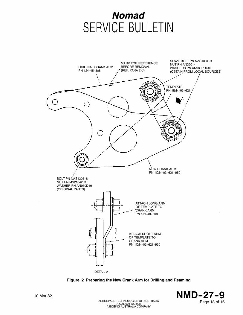
D. Temporarily assemble together the original crank arm PN 1/N--45--808, the new crank arm PN1C/N--03--621--950 and template PN 1B/N--03--621 using the attaching parts and method ofassembly shown in Figure 2.
NOTE
Ensure that the top of the original crank arm (Ref Para 2.C. is uppermost, and that boltPNNAS1303--8 is fitted through the predrilled reference hole in the newcrank armandthe bottom hole in the original crank arm. Close--tolerance bolts must be used in allpositions.

Nomad
10 Mar 82 NMD--27--9Page 5 of 16AEROSPACE TECHNOLOGIES OF AUSTRALIA
A.C.N. 008 622 008A BOEING AUSTRALIA COMPANY
CAUTION
DO NOT ATTEMPT TO DRILL THE ATTACHMENT HOLES IN THE NEW CRANKARM BY HAND.
E. Using a drill press, and utilising the attachment holes in the original crank arm as a guide, drill andream the three remaining attachment holes in the new crank arm to 0.1900/0.1908 inch dia.Disassemble the crank arms and discard template PN 1B/N--03--621 and the original crank arm PN1/N--45--808.
F. Assemble the new crank arm to the torque shaft assembly as shown in Figure 3. Fit the boltthrough the bottom attachment (reference) hole first, then check that the three remainingattachment bolts can be fitted. DO NOT FIT THE NUTS YET.
NOTE
If any bolt cannot be fitted due to misalignment of the crank arm holes with the holesin the mating flanges, ream the relevant holes to 0.1900/0.1920 inch dia.
G. Cheek that the diameters of the holes in the crank arm and the flanges of the torque tube do notexceed the outside diameters of the bolts by more than 0.002 inch.
NOTE
If any hole is damaged or drilled oversize, drill and ream the hole to 0.2031/0.2038 inchdia. then fit oversize bolt PNNAS6203--8X or PN NAS6203--10X to the 0.2031/0.2038inch dia hole(s) when assembling the crank arm to the torque shaft assembly. The longbolt (PN NAS6203--1OX) is used to accommodate the bonding lead. DO NOT FITTHE NUTS YET.
H. Measure the gap between one of the flanges and the new crank arm (Ref Figure 4). Fit laminatedshims PN 1D/N--03--621 (Ref. Figure 3) as required to ensure that the gap does not exceed 0.003inch. Secure the crank arm to the torque shaft assembly using original nuts and washers, ensuringthat the bonding lead terminal is correctly fitted (Ref Para 2.B.). Torque tighten the nuts to between25 and 30 lb inches.
I. Drill and ream the rigging hole in the torque lever assembly.
(1) Remove the nut PN AN316--4, washers PN AN960--416, washers PN AN960--416L and peenedbolt PN AN174--11A attaching the UPPER fork--end PN 1/N--45--889 to torque shaft leverassembly PN 1/N--45--950. Discard the bolt and nut, but retain the fork--end and the washers.
(2) Assemble template PN 1A/N--03--621 to the upper arm of the torque shaft lever assembly (RefFigure 5). Drill and ream the rigging hole in position illustrated. Remove the nut, washers and boltattaching template PN 1A/N--03--621 to the torque lever assembly. Discard the template, butretain the attaching parts.
NOTE
This rigging hole is for future use with rigging bar PN 1/N--88--180 as detailed in therigging procedure for the horizontal stabiliser (Ref Chap MM 27--40--00).

Nomad
NMD--27--910 Mar 82Page 6 of 16
AEROSPACE TECHNOLOGIES OF AUSTRALIAA.C.N. 008 622 008
A BOEING AUSTRALIA COMPANY
WARNING
UPPER FORK--END PN 1/N--45--889 AND LOWER FORK--END PN 3/N--45--888HAVE DIFFERENT HAND TURNBUCKLE THREADS TO PREVENT CROSSCONNECTION OF HORIZONTAL STABILIZER CONTROL CABLES. IT ISIMPERATIVE THAT FORK--END PN 1A--45--889 (LH THREAD AND MARKED“UPPER”) BE FITTED TO THE UPPER ARM OF THE TORQUE SHAFT LEVER,AND THAT FORK--END PN3/N--45--888 BE FITTED TO THE LOWERARMOF THETORQUE SHAFT LEVER. AFTER FITTING THE FORK--ENDS TO THE TORQUESHAFT LEVER THE PIVOT BOLTS ARE TO BE PERMANENTLY LOCKED BYPEENING THE BOLT END. AN INDEPENDENT INSPECTION SHOULD BEPERFORMED TO CHECK THAT THE FORK--ENDS HAVE BEEN CORRECTLYCONNECTED TO THEIR RESPECTIVE ARMS OF THE TORQUE SHAFT LEVER.
J. Connect the UPPER fork--end PN 1/N--45--889 to the upper arm of the torque shaft lever assemblyusing the attaching parts and method of assembly shown in Figure 1, Detail A. Torque tighten thenut to between 30 and 40 lb inches. Fit split pin and then peen bolt thread.
NOTE
Utilise originalwashers, fitting thinwashersPNAN960--416Las required to ensure thatthe fork--end will not be distorted when the nut is tightened. Use new bolt, castellatednut and split pin from kit.
K. Fit new LOWER fork--end.
(1) Remove the LOWER fork--end PN 1/N--45--888 from the torque shaft lever. Discard the fork--end,attaching bolt PN NAS1104--11 and nut PN AN316--4, but retain washers PN AN960--416 andAN960--416L.
(2) Connect new LOWER fork--endPA 3/N--45--888 to the torque shaft lever using the attachingpartsand method of assembly shown in Figure 1, Detail A. Torque tighten the nut to between 30 and40 lb inches. Fit split pin and then peen bolt thread. DO NOT RECONNECT CONTROLCABLE YET.
NOTE
Utilise originalwashers, fitting thinwashersPNAN960--416Las required to ensure thatthe fork--end will not be distorted when the nut is tightened. Use new bolt, castellatednut and split pin from kit.
L. Refit modified torque shaft assembly.
(1) Repart number the modified torque shaft assembly to 1/N--03--621 (or to 1/N--03--621/G48 if theautopilot quadrants are fitted).
Nomad
10 Mar 82 NMD--27--9Page 7 of 16AEROSPACE TECHNOLOGIES OF AUSTRALIA
A.C.N. 008 622 008A BOEING AUSTRALIA COMPANY
CAUTION
WHEN CONNECTING THE HORIZONTAL STABILIZER CONTROL CABLES TOTHE TORQUE SHAFT LEVER FORK--ENDS, ENSURE THAT THE CABLE WITHTHE LEFT HAND THREADED TURNBUCKLE IS CONNECTED TO THEFORK--ENDMARKED “UPPER”. THECABLEWITHTHERIGHTHANDTHREADEDTURNBUCKLE IS TO BE CONNECTED TO THE FORK--END MARKED “LOWER”.
(2) Refit the modified torque shaft assembly in the aircraft and reconnect the control cables to thetorque shaft lever fork--ends (Ref MM Chap 27--40--06).
M. Install the redesigned pulley mounting brackets (Mod N63) as detailed in Service BulletinNMD--27--15 to provide the correct cable run.
NOTES
(1) Trim control rod PN 1/N--03--603 or PN 1/N--30--184 is a modified assembly asrequired by Mod N398 (Refer Service Bulletin NMD--55--8).
(2) Trim tabs must be modified as detailed in Service Bulletin NMD--55--8 whencontrol rods PN 1/N--03--603 or PN 1/N--30--184 are fitted.
N. Remove the throttle box cover to gain access to the horizontal stabiliser trim indicator drumassembly PN 1/N--47--214.
O. Attach new label PN 1A/N--47--214 (N22) or PN 102A/N--47--214 (N24) to the horizontal stabilizertrim indicator drum.
(1) Hold the label in position around the trimdrumandalign the zeromark on the labelwith theexistingzero mark on the trim drum.
(2) Drill a 3/32 inch dia. hole in the trim drum to coincide with the punched hole near the zero markon the label.
(3) Rivet the label to the trim drum using a rivet PN MS20470AD3--3 or PN CCR274SS--3--1.
(4) Affix the label to the trim drum using Araldite.
(5) Repart number the trim drum assembly to 2/N--47--214 (N22) or 102/N--47--214 (N24).
P. Rig the horizontal stabiliser in accordance with MM Chap 27--40--00 or alternative procedure (RefPara 2.Q.) and the following note:
NOTE
On completion of rigging, check controls for correct sense of operation and for full andfree movement under all trim conditions. In particular ensure that positive clearanceexists between the tab and the horizontal stabiliser trailing edge structure through thefull range of stabiliser travel with full nose up trim selected.

Nomad
NMD--27--910 Mar 82Page 8 of 16
AEROSPACE TECHNOLOGIES OF AUSTRALIAA.C.N. 008 622 008
A BOEING AUSTRALIA COMPANY
Q. Alternative method of rigging the Horizontal Stabiliser.
The following procedure requires the use of an inclinometer with a minimum range of 35 degrees anda scale graduated in degrees and minutes. If this type of inclinometer is not available, templateNMD--27--9--3 (locally manufactured to dimensions shown in Figure 6) and a spirit levelwill be required.
(1) Level the aircraft (Ref MM Chap 8--00--00).
(2) Rig the horizontal stabiliser controls in the front fuselage (Ref. MM. Chap 27--40--00MaintenancePractices Para. 1.M2) steps (a) to (9) inclusive).
CAUTION
WHEN CONNECTING THE HORIZONTAL STABILIZER CONTROL CABLES TOTHE TORQUE SHAFT LEVER FORK--ENDS, ENSURE THAT THE CABLE WITHTHE LEFT HAND THREADED TURNBUCKLE IS CONNECTED TO THEFORK--ENDMARKED “UPPER”. THECABLEWITHTHERIGHTHANDTHREADEDTURNBUCKLE IS TO BE CONNECTED TO THE FORK--END MARKED “LOWER”.
(3) Connect the horizontal stabiliser control cables to the fork--ends attached to the upper and lowerarms of the torque shaft lever.
(4) Set the scale on the inclinometer to 32 degrees 30 minutes and place the inclinometer on theupper arm of the torque shaft lever.
NOTE
If an inclinometer is not available, place the template and spirit level in position on theupper arm of the torque shaft lever (Ref Figure 6).
(5) Adjust on both horizontal stabiliser control cables until the bubble in the inclinometer or spirit levelis centralised.
(6) Tension the control cables equally (Ref MM Chap 27--00--00).
(7) Check that after both control cables have been correctly tensioned the bubble in the inclinometeror spirit level is still centralised. Remove the inclinometer, or template and spirit level from theaircraft.
(8) Install the turnbuckle locking clips.
(9) Support the horizontal stabiliser anddisconnect the control rod, between themodified torque shaftassembly and the horizontal stabiliser, at the crank arm of the torque shaft. Retain the bolt, nutand washer, but discard the split pin.
(10) Remove the dorsal fin (Ref MM Chap 55--30--00).
(11) Place the rigging bar 1/N--88--183 (N22) at the --3 degree position on the extended shaft of thehorizontal stabiliser control rod connecting bolt, or rigging bar 1/N--88--181 (N24) at the --1 degreeposition on the connecting lt and secure in position with a 1/4 inch UNF nut.
(12) Connect the lower end of the rigging bar to the rigging bracket (Ref MM Chap 27--40--00 Figure201 Sheet 2) with a 1/4 inch UNF nut and bolt.

Nomad
10 Mar 82 NMD--27--9Page 9 of 16AEROSPACE TECHNOLOGIES OF AUSTRALIA
A.C.N. 008 622 008A BOEING AUSTRALIA COMPANY
(13) Adjust the control rod (disconnected at step (9)) if necessary, to enable the rod to be connectedto the torque shaft crank arm. If adjustment in rod length was necessary, cheek that the rodadjustable fork--end is “in safety” then torque tighten the locknut to between270and300 lb inches.Lockwire the nut to the fork--end.
(14) Connect the control rod to the torque shaft crank arm with bolt, washer and nut. Torque tightenthe nut to 40 lb inches then back--off the nut a minimum amount to enable a split pin PNMS24665--134 to be fitted. Fit the split pin.
(15) Remove the riggingpin PN1/N--88--82 from the horizontal stabiliser quadrant in,the front fuselage(Ref MM Chap 27--40--00 Figure 201 Sheet l).
CAUTION
ENSURE THAT THE HORIZONTAL STABILIZER CONTROL SYSTEM IS FREEFROM OBSTRUCTION.
(16) Check the horizontal stabiliser range of travel and adjust as necessary (Ref MM Chap 27--40--00Maintenance Practices Para 1(4)(1) to (r) and (t) to (w) inclusively).
NOTE
On completion of rigging, cheek controls for correct sense of operation and for full andfree movement under all trim conditions. In particular ensure that positive clearanceexists between the tab and the horizontal stabiliser trailing edge structure through thefull range of stabiliser travel with full nose up trim selected.
(17) Lower the aircraft to the ground (Ref MM Chap 7--00--00).
3. MATERIALS INFORMATION
A. Parts Required per Aircraft
(1) One kit PN NMD--27--9--1 (N22), or PN NMD--27--9--2 (N24) is required per aircraft. The kits forboth N22--Series Aircraft and N24--Series Aircraft are identical except for the modified horizontalstabiliser trim drum indicator label. The respective labels are identified by their part numbers andalso the kit in which they are included. Each kit comprises the following parts:
Item PN Title Qty1/N--45--1407--950 * Connecting rod 1MS24665--302 Split pin 1MS24665--134 Split pin 11C/N--03--621--950 Crank arm 11B/N--03--621 Template 11D/N--03--621 Shim 11A/N--03--621 Template 1NAS6204--11D Bolt 2AN320--4 Nut, castellated 2MS24665--153 Split pin 2

Nomad
NMD--27--910 Mar 82Page 10 of 16
AEROSPACE TECHNOLOGIES OF AUSTRALIAA.C.N. 008 622 008
A BOEING AUSTRALIA COMPANY
3/N--45--888 Fork end, LOWER 11A/N--47--214 Trim drum label (Kit PN NMD--27--9--1) 1102A/N--47--214 Trim drum label (Kit PN NMD--27--9--2) 1MS20470AD3--3 Rivet, or 1CCR274SS--3--1 Rivet Alt
NOTE
Connecting rod PN 1/N--45--1407--950 is short fitted and requires rod fork--end PN2/N--45--962 and nut PN AN315--7 from the discarded rod assembly PN 2/N--45--958 tocomplete the assembly (Ref Para 2.A. and Service Bulletin NMD--27--13 (Mod N426)).
(2) Parts modified and re--identified by the operator.
Title Original PN New PNConnecting rod assembly 2/N--45--958 2/N--45--1407Torque shaft assembly 1/N--45--953 1/N--03--621Torque shaft assembly * 1/N--45--953/G48 1/N--03--621/G48H/S trim indicator drum 1/N--47--214 2/N--47--214 (N22)
102/N--47--214 (N24)
* If Option G48 or G48--24 is fitted.
B. Parts required to modify spares
Item PN Title Qty per spare1C/N--03--621--950 Crank arm assembly 1 Torque shaft3/N--45--888 Fork--end 1 assemblyNAS6204--11D Bolt 2 1/N--45--953 orAN320--4 Nut, castellated 2 1/N--45--953/MS24665--153 Split pin 2 G48
1/N--45--1407--950 Connecting rod 1 Connecting Rod2/N--45--962 Fork--end 1 assemblyAN315--7 Nut 1 2/N--45--958
C. Removed Parts
Item PN Qty Title Instruction/Disposition2/N--45--958 1 Connecting rod assembly *1/N--45--808 1 Crank arm Scrap
* Retain fork--end PN 2/N--45--962 and nut PN AN315--7 but scrap connecting rod.
Nomad
10 Mar 82 NMD--27--9Page 11 of 16AEROSPACE TECHNOLOGIES OF AUSTRALIA
A.C.N. 008 622 008A BOEING AUSTRALIA COMPANY
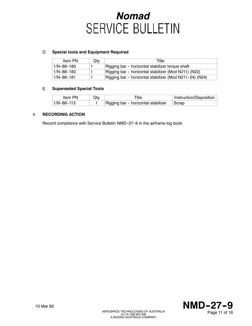
D. Special tools and Equipment Required
Item PN Qty Title1/N--88--180 1 Rigging bar -- horizontal stabilizer torque shaft1/N--88--183 1 Rigging bar -- horizontal stabilizer (Mod N211) (N22)1/N--88--181 1 Rigging bar -- horizontal stabilizer (Mod N211--24) (N24)
E. Superseded Special Tools
Item PN Qty Title Instruction/Disposition1/N--88--113 1 Rigging bar -- horizontal stabilizer Scrap
4. RECORDING ACTION
Record compliance with Service Bulletin NMD--27--9 in the airframe log book.

Nomad
NMD--27--910 Mar 82Page 12 of 16
AEROSPACE TECHNOLOGIES OF AUSTRALIAA.C.N. 008 622 008
A BOEING AUSTRALIA COMPANY
TORQUE SHAFT LEVERBEARING
WASHER PN AN960--416L(USE AS REQD)
WASHERPN AN960--416
BOLT PN NAS6204--11D
FORK END UPPERPN 1/N--45--889FORK END LOWERPN 3/N--45--888
WASHERPN AN960--416L(USE AS REQD)
WASHERPN AN960--416CASTELLATED NUTPN AN320--4TORQUE TIGHTEN TO30--40 lb in.PEEN BOLT THREAD
SPLIT PINPN MS24665--153
DETAIL B (POST MOD N211 AND N211--24)
BONDING LEAD
CONTROL ROD(REPLACE CONTROL RODPN 2/N--45--958 WITHNEW CONTROL RODPN 2/N--45--1407)
RETAIN NUTPN AN315--7RETAIN FORK--ENDPN 2/N--45--962
WHEN NUTS REPLACED BYANCHOR NUTS(AS ON LATER AIRCRAFT)TORQUE TIGHTENBOLTS TO 20--25 lb in.
NEW CRANK ARMPN 1C/N--03--621--950(POST MOD N211/N211--24)
TORQUE SHAFT LEVERFORK END(SEE DETAIL A)
TORQUE SHAFT LEVER
END FITTINGS
BEARING HOUSING
TURNBUCKLE
TORQUE SHAFT LEVERFORK--END(SEE DETAIL A)
HOLE FOR RIGGING PIN(PART OF RIGGING BARASSEMBLY PN 1/N--88--180)
Figure 1 Horizontal Stabiliser Torque Shaft and Control Rod Linkage
Nomad
10 Mar 82 NMD--27--9Page 13 of 16AEROSPACE TECHNOLOGIES OF AUSTRALIA
A.C.N. 008 622 008A BOEING AUSTRALIA COMPANY
ORIGINAL CRANK ARMPN 1/N--45--808
MARK FOR REFERENCEBEFORE REMOVAL(REF. PARA 2.C)
TEMPLATEPN 1B/N--03--621
SLAVE BOLT PN NAS1304--9NUT PN AN320--4WASHERS PN AN960PD416(OBTAIN FROM LOCAL SOURCES)
NEW CRANK ARMPN 1C/N--03--621--950
BOLT PN NAS1303--8NUT PN MS21042L3WASHER PN AN960D10(ORIGINAL PARTS)
ATTACH LONG ARMOF TEMPLATE TOCRANK ARMPN 1/N--48--808
ATTACH SHORT ARMOF TEMPLATE TOCRANK ARMPN 1C/N--03--621--950
DETAIL A
Figure 2 Preparing the New Crank Arm for Drilling and Reaming

Nomad
NMD--27--910 Mar 82Page 14 of 16
AEROSPACE TECHNOLOGIES OF AUSTRALIAA.C.N. 008 622 008
A BOEING AUSTRALIA COMPANY
BONDING LEAD
CRANK ARM
LAMINATED SHIMSPN 1D/N--03--621
TORQUE SHAFTASSEMBLY
Figure 3 Installation of New Crank Arm on Torque Shaft Assembly
BEFORE TIGHTENING NUTS CHECKGAP DOES NOT EXCEED 0.003 INCHUSE SHIM PN 1D/N--03--621AS REQUIRED
RECONNECTBONDINGLEAD
FLANGE
CRANK ARM PN 1C/N--03--621--950FLANGE
TORQUE TIGHTEN NUTSTO 25--30 lb in
Figure 4 Checking the Gap Between Crank Arm and Flanges

Nomad
10 Mar 82 NMD--27--9Page 15 of 16AEROSPACE TECHNOLOGIES OF AUSTRALIA
A.C.N. 008 622 008A BOEING AUSTRALIA COMPANY
UPPER ARM OF TORQUE SHAFT LEVER
DRILL AND REAM RIGGING HOLE 0.250/0.252 INCH DIA.
BOLT PN NAS6204--11D (FROM KIT)WASHERS PN AN960--416 (ORIGINAL)NUT PN AN320--4 (FROM KIT)
TEMPLATE PN 1A/N--03--621
Figure 5 Locating the Rigging Hole in the Torque Shaft Lever

Nomad
NMD--27--910 Mar 82Page 16 of 16
AEROSPACE TECHNOLOGIES OF AUSTRALIAA.C.N. 008 622 008
A BOEING AUSTRALIA COMPANY
NOT OT SCALE
10.00
11.86
ALL DIMENSIONS IN INCHESUNLESS INDICATED 6.37
PN NMD--27--9--3
90_32_30’
TEMPLATEMATERIAL--AL.ALLOY SHEET 0.10 THICK
SPIRIT LEVEL
TEMPLATEPN NMD--27--9--3
TORQUE SHAFT ASSEMBLY
32_30’
Figure 6 Template1