planning, execution and monitoring of masonry structuresfes.org.in/source-book/masonry_final.pdf ·...
TRANSCRIPT
FOUNDATION FOR ECOLOGICAL SECURITY
PLANNING, EXECUTION AND MONITORING OF MASONRY STRUCTURES
August 2008
A
SOURCE BOOK
FOR
0
A Manual For Planning, Execution And Monitoring
Of
Masonry Structures
Foundation For Ecological Security
August, 2008

INDEX Page no. • Definition of Dam 1
• Classification of dams 1
• Advantage and Disadvantage of cement masonry dam 2
• Survey for the team 3
• Dam design 4
• Basic concept of masonry structures 5
• Standard formats for design and cost estimation 5
• Drawings of masonry dam 6
• Rate analysis
1
Cement structure
Definition of dam: It is an impermeable structure constructed across the
drainage line for storage of water. The side of the dam where water is stored is
called the upstream side and other side of the dam is called downstream side.
During the site selection for water harvesting structures under the watershed
programmes, the cement masonry structures are usually preferred over the
earthen structures. The designing and cost estimation process of cement
masonry structures is a tedious job and requires skilled persons. However,
anyone who has a learning attitude can easily understand the underlying
principles. Watershed projects also focus on aspects that provide employment to
the rural community but the construction of the cement masonry structure
involves a very small component of unskilled labour cost. The proportion of wage
cost and non-wage cost for the construction of the masonry structure is in the
proportion of 40: 60. Hence, these structures should be planned only on such
sites that are not favorable for the construction of earthen structures.
Uses of dam: The stored water may be used for a variety of purposes that may
be irrigation, drinking, electricity generation, and flood control etc.
History of dam: It is hard to say that when was the first dam constructed but
based on the archeological findings, the first dam was constructed before 3000
to 5000 years ago. The first modern dam was constructed in Furnace, France in
1861, the design which is being mostly followed. The first dam (Aswan dam)
across the big river (Nile River) is constructed in 1902 in Egypt.
Classification of dams:
Dams are generally classified by three types:
Type I: On the basis of use
Geographical location, storage capacity and location of the dam are the three
main parameters for further classifying dams on the basis of use
a) Storage: The main purpose of this structure is to store the excess surface
runoff during the rainy season. It can further be used for irrigation, electricity

2
generation and the ground water recharge. Example: Rihand dam, Indira Sagar,
Nagarjuna Sagar and Bhakra Dam etc.
b) Irrigation: The main purpose of this dam is irrigation through canal network. All
minor irrigation dams are the examples of this class.
c) Flood control structure: The main purpose of this structure is to protect a
particular area from flooding by storing the water at flood times and releasing it
during the normal period. Farraka barage is one such barrage constructed on
River Ganga to protect Bangladesh from inundation.
On the basis of overflow and non overflow
A dam where water flows over the dam body is called an overflow dam and
otherwise it is called a non-overflow dam. All masonry structures are overflow
dams and all earthen dams are the examples of non-overflow dams.
On the basis of construction material/shape
a) Earthen dam: It is the dam constructed by earth therefore it is called earthen
dam.
b) RCC dam: It is constructed by concrete and steel bars hence it is called RCC
dam.
c) Concrete dam: Concrete is mainly used for construction of this structure.
d) Arch dam: shape of the dam is arch type hence it is called arch dam.
e) Steel dam: the dam constructed by steel thus, it is called steel dam.
f) Wooden dam: wooden planks are mainly used for construction of the wooden
dam.

3
Advantage and disadvantage of cement masonry dam
Earthen dam Masonry dam
Construction material is locally
available.
Construction material is not available
locally.
It mainly requires unskilled labor. It requires both skilled & unskilled
labor.
Height of the dam can be modified
easily.
Height cannot be modified unless there
is an additional provision in the
foundation for such a modification.
Wage cost and non-wage cost
proportion is 80: 20.
Wage cost and non-wage cost
proportion is 40: 60.
Initial construction cost is low. Initial construction cost is very high
Maintenance cost is high. Maintenance cost is low.
Foundation strata is not a major
constraint in site selection.
Foundation strata should be firm and
hard when selecting a site for such a
dam.
It can fail suddenly. It warns before failure.
It can be constructed up to a maximum
height of 30 m.
There is no limitation with regards to
the height of a dam.
Survey for the dam: Site of a dam is selected on the basis of its catchment area
and the total amount of runoff generated from the catchment. Following points
should be kept in mind while conducting survey for a dam:
• The banks of the drain should be high and firm.
• Width of the drain at the site should be narrow and the slope of the drain
bed should be gentle.
• The site should be approachable for an easy transportation of construction
materials.
• The submergence area of the dam should be marked on the ground.
• Conduct cross section survey at regular intervals across the drain to
estimate the storage capacity of the dam.
4
• Check the status of catchment area i.e. whether it is treated or untreated.
If it is not treated then a plan for the same should be made and
incorporated into the proposal of dam.
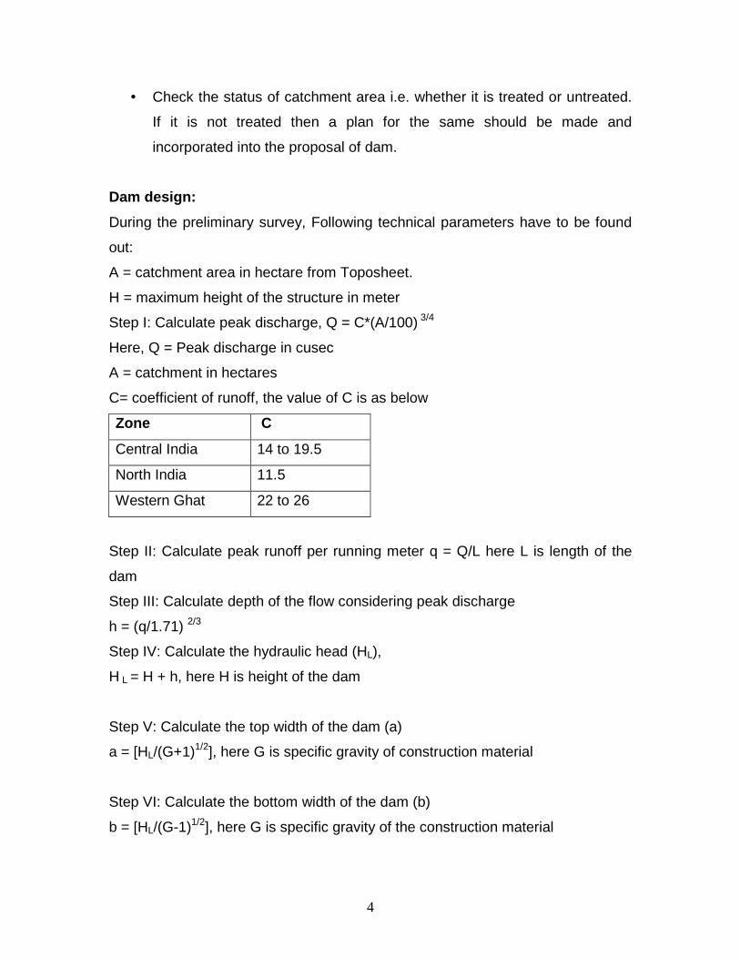
Dam design:
During the preliminary survey, Following technical parameters have to be found
out:
A = catchment area in hectare from Toposheet.
H = maximum height of the structure in meter
Step I: Calculate peak discharge, Q = C*(A/100) 3/4
Here, Q = Peak discharge in cusec
A = catchment in hectares
C= coefficient of runoff, the value of C is as below
Zone C
Central India 14 to 19.5
North India 11.5
Western Ghat 22 to 26
Step II: Calculate peak runoff per running meter q = Q/L here L is length of the
dam
Step III: Calculate depth of the flow considering peak discharge
h = (q/1.71) 2/3
Step IV: Calculate the hydraulic head (HL),
H L = H + h, here H is height of the dam
Step V: Calculate the top width of the dam (a)
a = [HL/(G+1)1/2], here G is specific gravity of construction material
Step VI: Calculate the bottom width of the dam (b)
b = [HL/(G-1)1/2], here G is specific gravity of the construction material
5
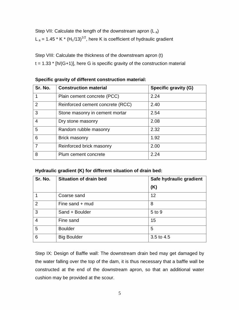
Step VII: Calculate the length of the downstream apron (L a)
L a = 1.45 * K * (HL/13)1/2, here K is coefficient of hydraulic gradient
Step VIII: Calculate the thickness of the downstream apron (t)
t = 1.33 * [h/(G+1)], here G is specific gravity of the construction material
Specific gravity of different construction material :
Sr. No. Construction material Specific gravity (G)
1 Plain cement concrete (PCC) 2.24
2 Reinforced cement concrete (RCC) 2.40
3 Stone masonry in cement mortar 2.54
4 Dry stone masonry 2.08
5 Random rubble masonry 2.32
6 Brick masonry 1.92
7 Reinforced brick masonry 2.00
8 Plum cement concrete 2.24
Hydraulic gradient (K) for different situation of d rain bed:
Sr. No. Situation of drain bed Safe hydraulic grad ient
(K)
1 Coarse sand 12
2 Fine sand + mud 8
3 Sand + Boulder 5 to 9
4 Fine sand 15
5 Boulder 5
6 Big Boulder 3.5 to 4.5
Step IX: Design of Baffle wall: The downstream drain bed may get damaged by
the water falling over the top of the dam, it is thus necessary that a baffle wall be
constructed at the end of the downstream apron, so that an additional water
cushion may be provided at the scour.
6
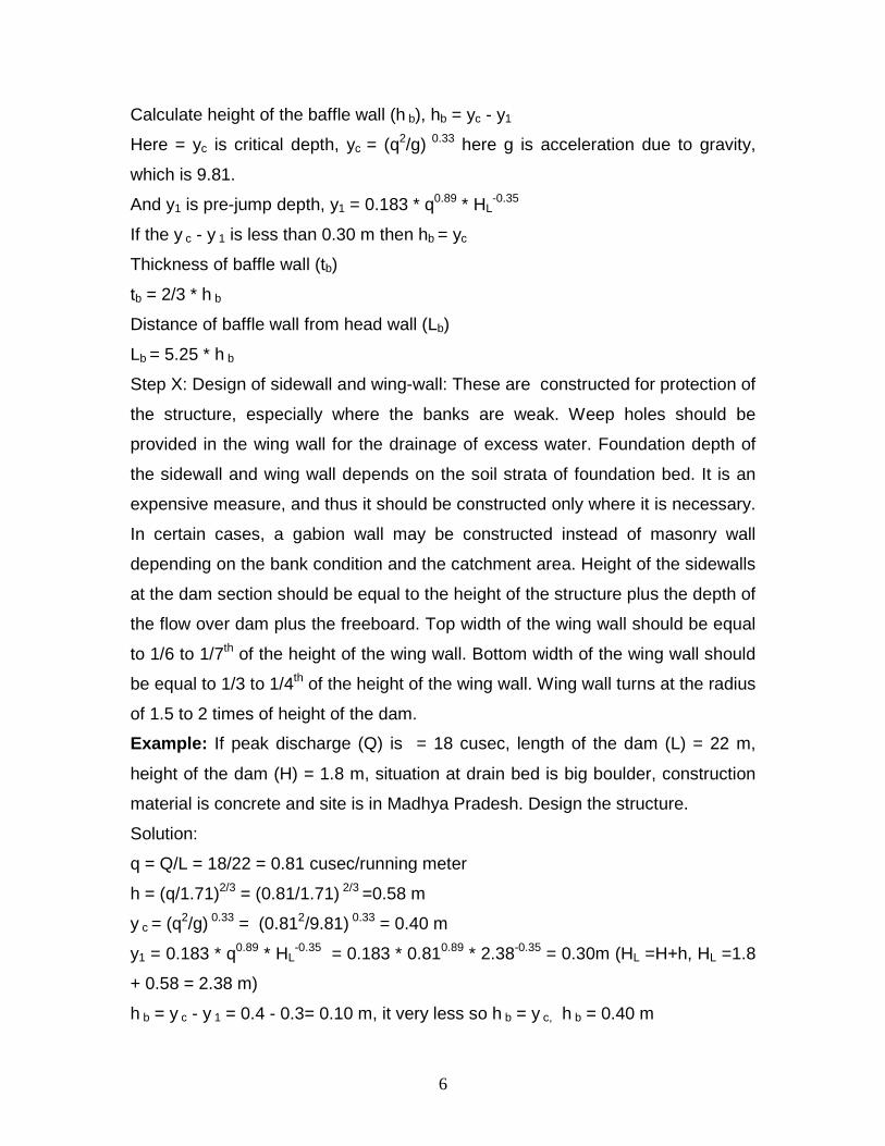
Calculate height of the baffle wall (h b), hb = yc - y1
Here = yc is critical depth, yc = (q2/g) 0.33 here g is acceleration due to gravity,
which is 9.81.
And y1 is pre-jump depth, y1 = 0.183 * q0.89 * HL-0.35
If the y c - y 1 is less than 0.30 m then hb = yc
Thickness of baffle wall (tb)
tb = 2/3 * h b
Distance of baffle wall from head wall (Lb)
Lb = 5.25 * h b
Step X: Design of sidewall and wing-wall: These are constructed for protection of
the structure, especially where the banks are weak. Weep holes should be
provided in the wing wall for the drainage of excess water. Foundation depth of
the sidewall and wing wall depends on the soil strata of foundation bed. It is an
expensive measure, and thus it should be constructed only where it is necessary.
In certain cases, a gabion wall may be constructed instead of masonry wall
depending on the bank condition and the catchment area. Height of the sidewalls
at the dam section should be equal to the height of the structure plus the depth of
the flow over dam plus the freeboard. Top width of the wing wall should be equal
to 1/6 to 1/7th of the height of the wing wall. Bottom width of the wing wall should
be equal to 1/3 to 1/4th of the height of the wing wall. Wing wall turns at the radius
of 1.5 to 2 times of height of the dam.
Example: If peak discharge (Q) is = 18 cusec, length of the dam (L) = 22 m,
height of the dam (H) = 1.8 m, situation at drain bed is big boulder, construction
material is concrete and site is in Madhya Pradesh. Design the structure.
Solution:
q = Q/L = 18/22 = 0.81 cusec/running meter
h = (q/1.71)2/3 = (0.81/1.71) 2/3 =0.58 m
y c = (q2/g) 0.33 = (0.812/9.81) 0.33 = 0.40 m
y1 = 0.183 * q0.89 * HL-0.35 = 0.183 * 0.810.89 * 2.38-0.35 = 0.30m (HL =H+h, HL =1.8
+ 0.58 = 2.38 m)
h b = y c - y 1 = 0.4 - 0.3= 0.10 m, it very less so h b = y c, h b = 0.40 m

7
Thickness of baffle wall (tb) = 2/3 * h b = 2/3 * 0.40 = 0.26 m
Distance of baffle wall from head wall (Lb) = 5.25 * h b = 5.25 * 0.40 = 2.1 m
Length of downstream apron (L a) = 1.45 * K * (HL/13)1/2 = 1.45 * 4.5 * (2.38/13)1/2
= 2.79 m
Thickness of downstream apron (t) = 1.33 * [h/(G+1)] = 1.33 * [0.58/(2.24+1)] =
0.62 m
Top width of dam (a) = [HL/(G+1)1/2] = [2.38/(2.24+1)1/2] = 1.11 m
Bottom width of dam (b) = [HL/(G-1)1/2] = [2.38/(2.24-1)1/2] = 1.8 m
Forces acting on dam wall:
• Stored water in upstream side of the dam body
• Self-weight of dam
• Uplift force of stored water
• Forces due to earthquake
• Ice force in cold terrain
• Wind force
• Force due to siltation
If height of the dam is less than 10 m, forces acting on the dam would be
negligible.
Horizontal forces due to stored water: Horizontal forces act on the dam body
mainly due to the standing water column. Resultant of the forces acts at H/3 from
the base of the dams. Formula for calculating horizontal force (P) on the dam
body is
P = 1/2 * w *H2, here w = specific unit weight of water = 1000Kg/m3 and H is
height of the stored water
Self weight force of the dam:
W = 1/2 * w * H * b *G
Here W is self-weight force in KG,
w is specific unit weight of water,
H is depth of water column,
G is specific gravity of construction material,
and b is bottom width of dam
8
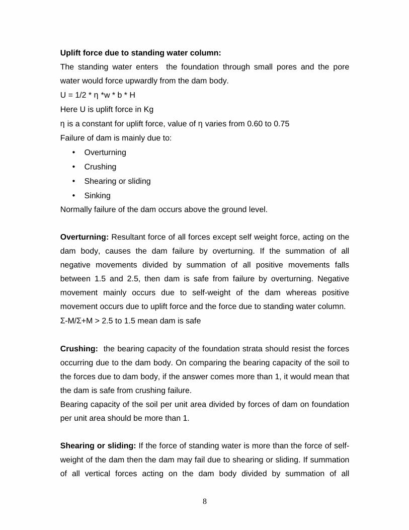
Uplift force due to standing water column:
The standing water enters the foundation through small pores and the pore
water would force upwardly from the dam body.
U = 1/2 * η *w * b * H
Here U is uplift force in Kg
η is a constant for uplift force, value of η varies from 0.60 to 0.75
Failure of dam is mainly due to:
• Overturning
• Crushing
• Shearing or sliding
• Sinking
Normally failure of the dam occurs above the ground level.
Overturning: Resultant force of all forces except self weight force, acting on the
dam body, causes the dam failure by overturning. If the summation of all
negative movements divided by summation of all positive movements falls
between 1.5 and 2.5, then dam is safe from failure by overturning. Negative
movement mainly occurs due to self-weight of the dam whereas positive
movement occurs due to uplift force and the force due to standing water column.
Σ-M/Σ+M > 2.5 to 1.5 mean dam is safe
Crushing: the bearing capacity of the foundation strata should resist the forces
occurring due to the dam body. On comparing the bearing capacity of the soil to
the forces due to dam body, if the answer comes more than 1, it would mean that
the dam is safe from crushing failure.
Bearing capacity of the soil per unit area divided by forces of dam on foundation
per unit area should be more than 1.
Shearing or sliding: If the force of standing water is more than the force of self-
weight of the dam then the dam may fail due to shearing or sliding. If summation
of all vertical forces acting on the dam body divided by summation of all

9
horizontal forces acting on the dam is more than 1, it would mean dam is safe
from shearing or sliding failure. Friction constant is 0.75.
Example1: Silent features of the dam are as follows: Length of the head wall =
32 m, catchment area = 200 hectares, construction material RCC, situation at
drain bed is big boulder, height of the head wall of the dam is 3.2 m, location of
the dam is in Central India. Design the dam.
Solution:
Q= C *(A/100) 3/4 = 14 * (200/100) 3/4 = 23.54 cusec
Here, C = 14 and A = 200 ha
q = Q/L = 23.54/ 32 = 0.73 m
h = (q/1.71)2/3 = (0.74/1.71)2/3 = 0.54 m
Hydraulic head (HL) = H + h = 3.2 + 0.54 = 3.74 m
y c = (q2/g) 0.33 = (0.732/9.81) 0.33 = 0.44 m
y1 = 0.183 * q0.89 * HL-0.35 = 0.183 * 0.730.89 * 3.74-0.35 = 0.35 m
h b = y c - y 1 = 0.44-0.35= 0.09m, it is very less hence, h b = y c, h b = 0.44 m
Thickness of baffle wall (tb) = 2/3 * h b = 2/3 * 0.44 = 0.29 m
Distance of baffle wall from head wall (Lb) = 5.25 * h b = 5.25 * 0.44 = 2.31 m
Length of downstream apron (La) = 1.45 * K * (HL/13) 1/2 = 1.45 * 4.5 * (3.74/13) 1/2
= 3.50 m
Thickness of downstream apron (t) = 1.33 * [h/(G+1)] = 1.33 * [0.54/(2.24+1)] =
0.62 m
Top width of dam (a) = [HL/(G+1) 1/2] = [3.74/(2.24+1) 1/2] = 2.07 m
Bottom width of dam (b) = [HL/(G-1) 1/2] = [3.74/(2.24-1) 1/2] = 3.35 m
Force of standing water (P) = 1/2 * w * H2 = 1/2 * 1000 *3.2 2 = 5120 Kg
Self weight of dam = 1/2 * w * H *b *G = 1/2 *1000 * 3.2 *3.35 *2.24 = 12006 Kg
Uplift force (U) = 1/2 * η * w *b *H = 1/2 * 0.75 *1000 *3.35 *3.2 = 4020 Kg
Negative movement due to self weight of dam = Self weight of dam x
perpendicular distance from toe of the dam (b/2)
= 12006 * 3.35/2 = 201110 Kg-m

10
Positive movement due to force of water = force of water X perpendicular
distance from toe of dam (H/3)
= 5120 * 3.2/3 = 5461 Kg-m
Positive movement due to uplift force of water = uplift force of water X
perpendicular distance from toe of the dam (b/2)
= 4020 * 3.35/2 = 6733.5 Kg-m
Shearing or sliding check:
Summation of vertical forces acting on dam body divided by summation of
horizontal forces acting on dam body should be more than 1
µ = 0.75
= (12006-4020)/5120
= 1.56 >1 hence OK
Check for Overturning
= Σ -M/ Σ +M >2.5 to 1.5
= 20110/12194
=1.64>1.5 hence OK
11
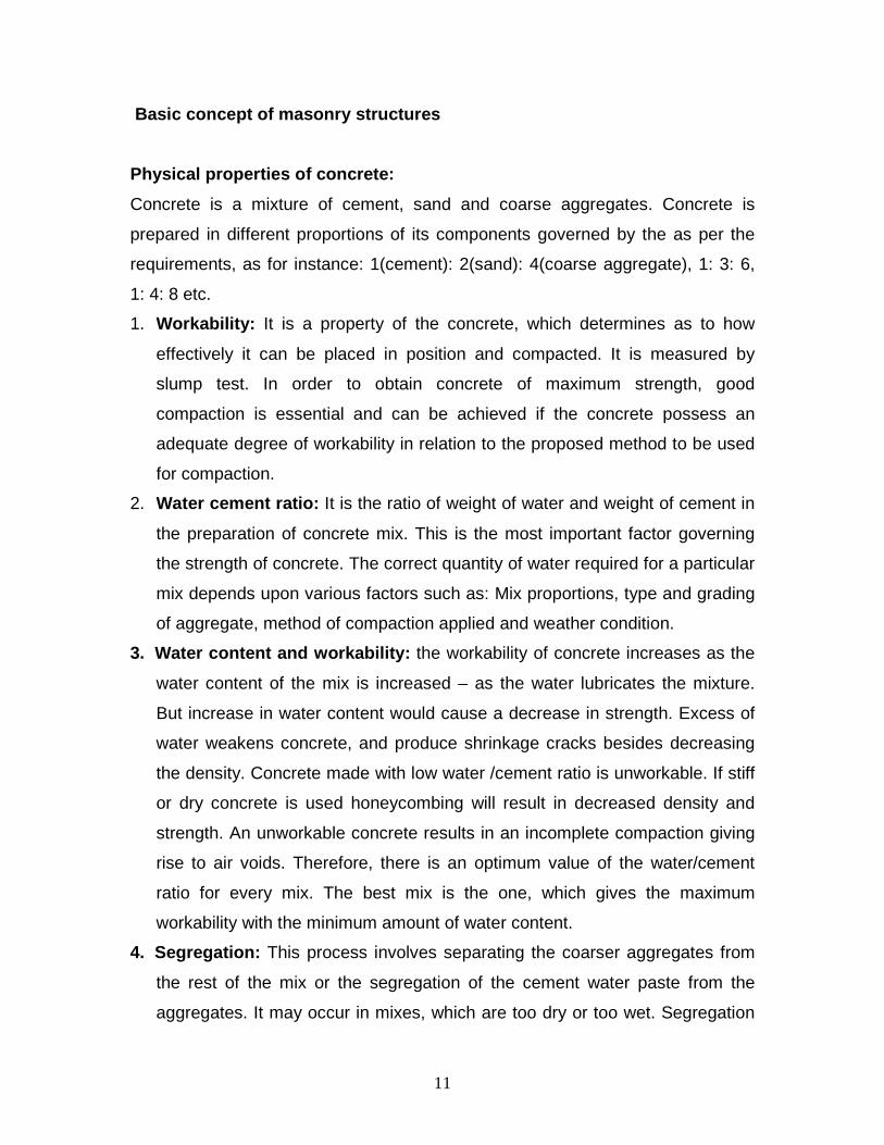
Basic concept of masonry structures
Physical properties of concrete:
Concrete is a mixture of cement, sand and coarse aggregates. Concrete is
prepared in different proportions of its components governed by the as per the
requirements, as for instance: 1(cement): 2(sand): 4(coarse aggregate), 1: 3: 6,
1: 4: 8 etc.
1. Workability: It is a property of the concrete, which determines as to how
effectively it can be placed in position and compacted. It is measured by
slump test. In order to obtain concrete of maximum strength, good
compaction is essential and can be achieved if the concrete possess an
adequate degree of workability in relation to the proposed method to be used
for compaction.
2. Water cement ratio: It is the ratio of weight of water and weight of cement in
the preparation of concrete mix. This is the most important factor governing
the strength of concrete. The correct quantity of water required for a particular
mix depends upon various factors such as: Mix proportions, type and grading
of aggregate, method of compaction applied and weather condition.
3. Water content and workability: the workability of concrete increases as the
water content of the mix is increased – as the water lubricates the mixture.
But increase in water content would cause a decrease in strength. Excess of
water weakens concrete, and produce shrinkage cracks besides decreasing
the density. Concrete made with low water /cement ratio is unworkable. If stiff
or dry concrete is used honeycombing will result in decreased density and
strength. An unworkable concrete results in an incomplete compaction giving
rise to air voids. Therefore, there is an optimum value of the water/cement
ratio for every mix. The best mix is the one, which gives the maximum
workability with the minimum amount of water content.
4. Segregation: This process involves separating the coarser aggregates from
the rest of the mix or the segregation of the cement water paste from the
aggregates. It may occur in mixes, which are too dry or too wet. Segregation

12
leads to the lack of uniformity causing honeycombing which reduces the
strength and durability of the structure.
5. Bleeding: It is the appearance of a watery scum on the surface of a concrete
after compaction. It is an indicator that there is too much water or deficiency
of fine material in the mix, or that too much tampering has been done. This
scum should be removed. Bleeding makes weak joints between successive
lifts in structural work.
6. Hydration of cement: When water is added to cement, the cement hydrates;
and calcium hydroxide or hydrated lime is librated. During the chemical
reaction, during the setting and hardening of the cement, an increase in
temperature occurs and a considerable quantity of heat is evolved. Hydration
of cement is incomplete in an adequate quantity of water. If the water cement
ratio is less than 0.4 to 0.5, the complete hydration of cement will not occur.
7. Slump test: It is a test conducted at the field for the workability of the
concrete.
8. Strength: The strength of hardened concrete mainly depends upon: a) water
cement ratio b) the quality and characteristics of cement c) the degree of
compaction obtained in the concrete d) curing and e) age of the concrete
9. Shrinkage: Concrete shrinks during setting and drying. The hydration of
cement produces shrinkage cracks. The drying shrinkage increases due to an
increase in the cement content or the water content.
10. Quality of water for concrete: Water for concrete should be clean and free
from any oils, acids, alkalis, vegetables or other organic impurities. In general,
water fit to drink is suitable for concrete.
13
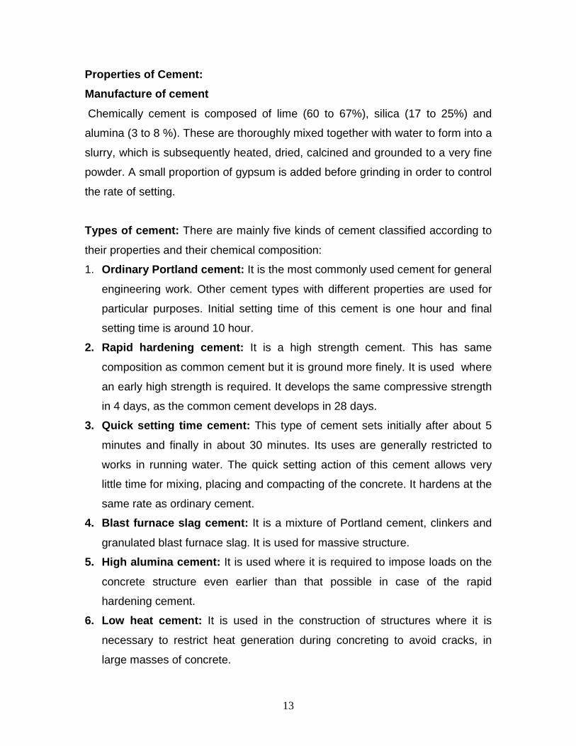
Properties of Cement:
Manufacture of cement
Chemically cement is composed of lime (60 to 67%), silica (17 to 25%) and
alumina (3 to 8 %). These are thoroughly mixed together with water to form into a
slurry, which is subsequently heated, dried, calcined and grounded to a very fine
powder. A small proportion of gypsum is added before grinding in order to control
the rate of setting.
Types of cement: There are mainly five kinds of cement classified according to
their properties and their chemical composition:
1. Ordinary Portland cement: It is the most commonly used cement for general
engineering work. Other cement types with different properties are used for
particular purposes. Initial setting time of this cement is one hour and final
setting time is around 10 hour.
2. Rapid hardening cement: It is a high strength cement. This has same
composition as common cement but it is ground more finely. It is used where
an early high strength is required. It develops the same compressive strength
in 4 days, as the common cement develops in 28 days.
3. Quick setting time cement: This type of cement sets initially after about 5
minutes and finally in about 30 minutes. Its uses are generally restricted to
works in running water. The quick setting action of this cement allows very
little time for mixing, placing and compacting of the concrete. It hardens at the
same rate as ordinary cement.
4. Blast furnace slag cement: It is a mixture of Portland cement, clinkers and
granulated blast furnace slag. It is used for massive structure.
5. High alumina cement: It is used where it is required to impose loads on the
concrete structure even earlier than that possible in case of the rapid
hardening cement.
6. Low heat cement: It is used in the construction of structures where it is
necessary to restrict heat generation during concreting to avoid cracks, in
large masses of concrete.
14
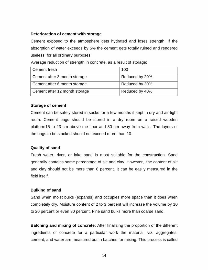
Deterioration of cement with storage
Cement exposed to the atmosphere gets hydrated and loses strength. If the
absorption of water exceeds by 5% the cement gets totally ruined and rendered
useless for all ordinary purposes.
Average reduction of strength in concrete, as a result of storage:
Cement fresh 100
Cement after 3 month storage Reduced by 20%
Cement after 6 month storage Reduced by 30%
Cement after 12 month storage Reduced by 40%
Storage of cement
Cement can be safely stored in sacks for a few months if kept in dry and air tight
room. Cement bags should be stored in a dry room on a raised wooden
platform15 to 23 cm above the floor and 30 cm away from walls. The layers of
the bags to be stacked should not exceed more than 10.
Quality of sand
Fresh water, river, or lake sand is most suitable for the construction. Sand
generally contains some percentage of silt and clay. However, the content of silt
and clay should not be more than 8 percent. It can be easily measured in the
field itself.
Bulking of sand
Sand when moist bulks (expands) and occupies more space than it does when
completely dry. Moisture content of 2 to 3 percent will increase the volume by 10
to 20 percent or even 30 percent. Fine sand bulks more than coarse sand.
Batching and mixing of concrete: After finalizing the proportion of the different
ingredients of concrete for a particular work the material, viz. aggregates,
cement, and water are measured out in batches for mixing. This process is called

15
batching. For measuring aggregates and sand, wooden box is made in units of
one whole bag of cement, i.e. in unit of 35 liters. For example a convenient size
of box would be 40 cm long, 35 cm wide and 25 cm deep. Overall capacity of this
box should be 35 liter.
Quantity of water, sand and aggregates per bag of c ement (35 lit):
Mix Water (liter) Sand (liter) Aggregate (liter)
1:2:4 29 to 32 70 140
1:3:6 34 to 36 105 210
1:4:8 45 to 47 140 280
Note: If the mix is prepared by mixer machine than quantity of water can be
reduced by about 20%. If the sand is wet, increase its quantity by 25% and
reduce quantity of water by 20%.
Hand mixing
It should be done on clean paved platform of size 3 m X 3 m with strips along
three sides. Cement and sand should be first mixed dry, followed with the
addition of the aggregate. The entire mixture should then be turned over 3 times
(dry), followed by 5 more times (wet) and thoroughly mixed until the concrete is
of uniform color.
Setting time retarding admixture
Addition of sugar while mixing water with the concrete is found to delay the
setting of the cement. It has been found that the addition of 0.05 percent of
sugar, by weight of cement, is increases the setting time of concrete by about
two hours in outdoor hot weather condition. Overdose of sugar is thus harmful.

16
Curing of concrete
When water is added to the cement, chemical reactions occur (hydration of
cement), which result in setting and hardening of the cement. Usually, mixing
water is sufficient to bring about the initial hydration of cement. However, if there
is insufficient water in the concrete for the complete hydration of the cement
during the setting period, the concrete does not develop its full strength. Curing
thus becomes necessary for at least 14 days. 100% strength can be achieved
only, if the curing is continued up to 28 days.
Compressive strength of ordinary Portland cement at different ages:
3 days 40%
7 days 65%
28 days 100%
3 months 115%
6 months 120%
12 months 130%

17
Standard Formats for Design and cost estimation:
Hydraulic design of structure Calculation for peak runoff by Rational formula
(For Catchment up to 1300 ha) Sr. Particulars Unit 1 Catchment area 1200 hectare 2 Land use with area a) Wood land (A1) 1200 hectare b) Pasture land (A2) 0 hectare c) Cultivated land (A3) 0 hectare d) Urban area (A4) 0 hectare 3 Topography with area Flat (0-5%) 1200 hectare Rolling (5-10%) hectare Hilly (10-30%) hectare 4 Coefficient of runoff a) C1 0.6 b) C2 0.6 c) C3 0.6 d) C4 0.6
Weighted C= (A1*C1+A2*C2+A3*C3+A4*C4)/(A1+A2+A3+A4) 0.6
5 Length of maximum length of travel from remotest point (L) 3000 meter
6 Difference in head between remotest point and the point of disposal (H) 15 meter
7 Time of concentration (t)= {(0.01947*(L3/H)0.5)0.77)}/60 1.19 hour
8 Constant for the calculation of rainfall intensity (Nearest station: Veraval)
a) K 7.787 b) a 0.2087 c) b 0.5 d) n 0.8908 9 Recurrence interval (T) 25 Year 10 Peak rainfall intensity (I) = 10* [(K*Ta)/ (t+b)n 95.671 mm/hour 11 Peak discharge (Q) = CIA/360 191.341 cum/sec
Calculation for peak runoff by Dicken's formula (For Catchment more than 130 0 ha)
Sr. Particulars Unit 1 Catchment area (A) 500 hectare 2 Runoff coefficient ( C ) 14 3 Peak discharge (Q) = C*(A/100)0.75 46.81 cum/sec

18
Structural design of structure
Sr. No. Particulars Unit
Designed dimensions
Dimensions taken for estimate
1 Peak discharge (Q) cum/sec 46.81 46.81
2 Depth of flow over head wall (h) = (Q/(1.71*Lhw))2/3 meter 1.23 1.23
3 Net Freeboard (F) = (TBL-HFL) generally taken is 0.5m meter 0.5 0.50
A Details of head wall
1 Length of head wall (Lhw) meter 20 20.00
2 Height of head wall (Hhw) meter 1.9 1.90
3 Top width of head wall (TWhw) = (Hhw+ h)/ sq root of (bulk density of masonry+1) meter 1.74 1.74
4 Bottom width of head wall (BWhw) = (Hhw+h)/sq root of (bulk density-1) meter 2.80 2.80
5 Foundation depth of head wall (Dhw)= 1.5*0.47*(Q/Hhw)1/3 meter 2.05 2.05
B Details of head wall extension
1 Length of one side head wall extension (Lhwe) = Hhw+h+1 meter 4.13 4.13
2 Top width of head wall extension (TWhwe) = generally taken as 0.50 m meter 0.5 0.50
3 Bottom width of head wall extension (BWhwe) = 0.4*(Hhw+h+F) meter 1.45 1.45
4 Height of head wall extension (Hhwe) = (Hhw+f+F) meter 3.63 3.63
5 Foundation depth of head wall extension (Dhwe) = Foundation depth of head wall (Dhw) meter 2.05 2.05
C Details of downstream side sidewall
1 Length of d/s side wall (Ldsw) = TWhw+(0.75*(Hhw+h))+Hhw meter 5.99 5.99

19
2 Top width of d/s side wall (TWdsw) = generally kept 0.50m meter 0.5 0.50
3 Bottom width of d/s side wall (BWdsw) = Bottom width of head wall extension (BWhwe) meter 1.45 1.45
4 Foundation depth of d/s side wall (Ddsw) = Depends on site conditions meter 0.5 0.5
5 Maximum height of d/s side wall (Hmxdsw) = height of head wall extension (Hhwe) meter 3.63 3.63
6
Minimum height of d/s side wall (Hmidsw) = generally kept half of Maximum height of d/s side wall (Hmxdsw) meter 1.82 1.82
D Details of upstream side sidewall
1 Length of u/s side wall (Lusw) = Length of d/s side wall (Ldsw)/2 meter 2.994 2.994
2 Top width of u/s side wall (TWusw) = generally kept 0.50m meter 0.5 0.50
3 Bottom width of u/s side wall (BWusw) = Bottom width of d/s side wall (BWdsw) meter 1.45 1.45
4 Foundation depth of u/s side wall (Dusw) = Depends on site conditions meter 0.5 0.5
5 Maximum height of u/s side wall (Hmxusw) = Maximum height of d/s side wall (Hmxdsw) meter 3.63 3.63
6 Minimum height of u/s side wall (Hmiusw) = Minimum height of d/s side wall (Hmidsw) meter 1.82 1.82
E Details of downstream side wing wall
1 Length of d/s wing wall (Ldww) = 2.25*h meter 2.77 2.77
2 Top width of d/s wing wall (TWdww) = Top width of d/s side wall (TWdsw) meter 0.5 0.50
3 Bottom width of d/s wing wall (BWdww) = Bottom width of d/s side wall (BWdsw) meter 1.45 1.45
4 Foundation depth of d/s wing wall foundation (Ddww) = Foundation depth of d/s side wall (Ddsw) meter 0.5 0.50
5 Height of d/s wing wall (Hdww) = Minimum height of d/s side wall (Hmidsw) meter 1.82 1.82
F Details of upstream side wing wall

20
1 Length of u/s wing wall (Luws) = Length of d/s wing wall (Ldww) meter 2.77 2.77
2 Top width of u/s wing wall (TWuww) = Top width of u/s side wall (TWusw) meter 0.5 0.50
3 Bottom width of u/s wing wall (BWuww) = Bottom width of u/s side wall (BWusw) meter 1.45 1.45
4 Foundation depth of u/s wing wall (Duww) = Foundation depth of u/s side wall (Dusw) meter 0.5 0.5
5 Height of u/s wing wall (Huww) = Minimum height of u/s side wall (Hmiusw) meter 1.82 1.82
G Details of downstream side apron
1 Width of d/s apron (Wda) = Length of d/s side wall (Ldsw) - Bottom width of head wall (BWhw) meter 3.19 3.19
2 Length of d/s apron (Lda) = Length of head wall (Lhw) meter 20 20
3 Thickness of d/s apron (Tda) = 1.33*(h/(G+1)) meter 0.50 0.60
H Details of upstream side apron
1 Width of u/s apron (Wua) = Width of u/s apron (Wda)/2 meter 1.59 1.59
2 Length of u/s apron (Lua) = Length of head wall (Lhw) meter 20 20
3 Thickness of u/s apron (Tua) = Thickness of d/s apron (Tda)/2 meter 0.25 0.40
I Details of downstream side Toe wall
1 Length of d/s toe wall (Ldtw) = Length of d/s apron (Lda) meter 20 20
2 Top and Bottom Width of toe wall (Wdtw) = genrally kept 0.50m meter 0.5 0.5
3 Height of d/s toe wall (Hdtw) = generally kept 0.50m meter 0.5 0.5
4 Foundation depth of toe wall (Ddtw) = Foundation depth of head wall (Dhw) meter 2.05 2.05

21
Measurement Sheet
S.N. Particulars No. Length Width H/D/T Quantity
1 Foundation excavation (BW+30cm)
1.1 Head wall 1 20.00 3.10 2.05 127.27
1.2 Head wall extension 2 4.13 1.75 2.05 29.73
1.3 Side wall (Downstream side) 2 5.99 1.75 0.50 10.50
1.4 Side wall (Upstream side) 2 2.99 1.75 0.50 5.25
1.5 Apron (Downstream side) 1 20.00 3.19 0.60 38.22
1.6 Apron (Upstream side) 1 20.00 1.59 0.40 12.74
1.7 Wing wall (Downstream side) 2 2.77 1.75 0.50 4.86
1.8 Wing wall (Upstream side) 2 2.77 1.75 0.50 4.86
1.9 Toe wall (Downstream side only) 1 20.00 0.80 2.05 32.82
TOTAL 266.26
2 P.C.C. in foundation base (BW+15cm)
1.1 Head wall 1 20.00 2.95 0.30 17.71
1.2 Head wall extension 2 4.13 1.60 0.30 3.98
1.3 Side wall (Downstream side) 2 5.99 1.60 0.30 5.76
1.4 Side wall (Upstream side) 2 2.99 1.60 0.30 2.88
1.5 Apron (Downstream side) 1 20.00 3.04 0.30 18.21
1.6 Apron (Upstream side) 1 20.00 1.44 0.30 8.66
1.7 Wing wall (Downstream side) 2 2.77 1.60 0.20 1.78
1.8 Wing wall (Upstream side) 2 2.77 1.60 0.20 1.78
1.9 Toe wall (Downstream side only) 1 20.00 0.65 0.30 3.90
TOTAL 64.65
3 R.R. masonry in foundation
1.1 Head wall 1 20.00 2.80 1.75 98.15
1.2 Head wall extension 2 4.13 1.45 1.75 21.04
1.3 Side wall (Downstream side) 2 5.99 1.45 0.20 3.48
1.4 Side wall (Upstream side) 2 2.99 1.45 0.20 1.74
1.5 Apron (Downstream side) 1 20.00 2.89 0.30 17.31
1.6 Apron (Upstream side) 1 20.00 1.29 0.10 2.59
1.7 Wing wall (Downstream side) 2 2.77 1.45 0.30 2.42
1.8 Wing wall (Upstream side) 2 2.77 1.45 0.30 2.42
1.9 Toe wall (Downstream side only) 1 20.00 0.50 1.75 17.51
Total 166.66

22
4 R.R. masonry in superstructure
1.1 Head wall 1 20.00 2.27 1.90 86.26
1.2 Head wall extension 2 4.13 0.98 3.63 29.32
1.3 Side wall (Downstream side) 2 5.99 0.98 2.72 31.86
1.4 Side wall (Upstream side) 2 2.99 0.98 2.72 15.93
1.5 Apron (Downstream side) 1 0.00 0.00 0.00 0.00
1.6 Apron (Upstream side) 1 0.00 0.00 0.00 0.00
1.7 Wing wall (Downstream side) 2 2.77 0.98 1.82 9.84
1.8 Wing wall (Upstream side) 2 2.77 0.98 1.82 9.84
1.9 Toe wall (Downstream side only) 1 20.00 0.50 0.50 5.00
Total 188.05
5 P.C.C. coping
1.1 Head wall 1 20.00 1.74 0.10 3.48
1.2 Head wall extension 2 4.13 0.50 0.10 0.41
1.3 Side wall (Downstream side) 2 5.99 0.50 0.10 0.60
1.4 Side wall (Upstream side) 2 2.99 0.50 0.10 0.30
1.5 Apron (Downstream side) 1 20.00 3.19 0.10 6.37
1.6 Apron (Upstream side) 1 20.00 1.59 0.10 3.19
1.7 Wing wall (Downstream side) 2 2.77 0.50 0.10 0.28
1.8 Wing wall (Upstream side) 2 2.77 0.50 0.10 0.28
1.9 Toe wall (Downstream side only) 1 20.00 0.50 0.10 1.00
Total 15.90
6 Plastering 20mm thick in cement mortar
1.1 Head wall 2 20.00 1.90 76.00
1.2 Head wall extension 4 4.13 3.63 60.05
1.3 Side wall (Downstream side) 4 5.99 2.72 65.25
1.4 Side wall (Upstream side) 4 2.99 2.72 32.63
1.5 Apron (Downstream side) 1 20.00 3.19 63.71
1.6 Apron (Upstream side) 1 20.00 1.59 31.85
1.7 Wing wall (Downstream side) 4 2.77 1.82 20.15
1.8 Wing wall (Upstream side) 4 2.77 1.82 20.15
1.9 Toe wall (Downstream side only) 2 20.00 0.50 20.00
Total 389.80
7 Soil filling after construction 34.95

23
Abstract sheet
S.N. Particulars Ratio Volume Unit Rate Cost
1 Foundation excavation & filling 301.21 Cum
As per BSR 2007 page no-1, item no.(B), (C),(E).
1.1 Hard soil 40% 120.48 Cum 44.20 5325
1.2 Disintegrated rock 35% 105.42 Cum 70.00 7380
1.3 Rock required blasting 25% 75.30 Cum 332.4 25030
As per BSR 2007 page no-2, item no. 13(A).
2 P.C.C. In foundation base Ratio 1:4:8 64.65 Cum 1600 103442
As per BSR 2007 page no-12, item no.164.
3 R.R. masonry in foundation Ratio 1:6 166.66 Cum 1500 249984
As per BSR 2007 page no-12, item no 164 & page no-3, item no.28.
4 R.R. masonry in superstructure Ratio 1:6 188.05 Cum 1569.7 295184
As per BSR 2007 page no-12, item no.166.
5 P.C.C. coping Ratio 1:2:4 15.90 Cum 2100 33385
As per BSR 2007 page no-6, item no 72 (B).
6 Plastering - 20mm in cement mortar Ratio 1:4 389.80 Sqm 80.00 31184
7 As per BSR 2007 - Annexure - 4.
Additional Transportation cost for more than 20km lead 30.00 21867
Total cost
Rs.772,781
A Contingencies Approximately @ 3.0% Rs.23,183
Grand Total Rs.795,964

24
Labour and Material Requirement
S.N. Particular Cement bags Sand Aggregate Boulder Remark
Rs.220 Rs.400 Rs.600 Rs.500 Volume Cum
1 P.C.C. in foundation base 3.45 0.46 0.92 Mtrl. Cost
150 cum for 100 cum PCC
Ratio 1:4:8 223.06 29.74 59.48 96,657
2 R.R.M. in foundation 2.01 0.36 Mtrl. Cost 1.25
42+125 cum for 100 cum of work
Ratio 1:6 335.42 60.00 201,951 208.32
3 R.R.M. in superstructure 2.01 0.36 Mtrl. Cost 1.25
42+100 cum for 100 cum of work
Ratio 1:6 378.48 67.70 227,878 235.06
125 cum for 100 cum of work
4 P.C.C. coping 6.33 0.43 0.85 Mtrl. Cost 150cum for 100 cum PCC
Ratio 1:2:4 100.56 6.84 13.51 32,965
5 Plastering - 20mm in cement mortar 0.14 0.025 Mtrl. Cost
2.5 Cum for 100Sqm of work
Ratio 1:4 70.05 9.74 0.00 Rs.19,308
TOTAL QUANTITY 1107.57 174.01 72.99 443.38 728.91
Total cost of materials Rs.243,666 Rs.69,606 Rs.43,795
Rs.221,692 Rs.578,759
Rs. 140
Recent minimum wage for mason
Labour Cost
Mandays of Labour
Cost of Sem.skilled mason
Mandays of mason
Total Cost of Labour & Mtrl.
Rs. 73
Recent minimum wage for labour
1 Foundation excavation & filling 30783 422 30783
2 P.C.C. in foundation base 10344 142 5172 37 112173
3 R.R.M. in foundation 49997 685 24998 179 276946
4 R.R.M. in superstructure 70844 970 35422 253 334144
5 P.C.C. coping 4006 55 2003 14 38974
6 Plastering - 20mm in cement mortar 5613 77 5613 40 30534
Total 171588 2351 73209 523 823555
25
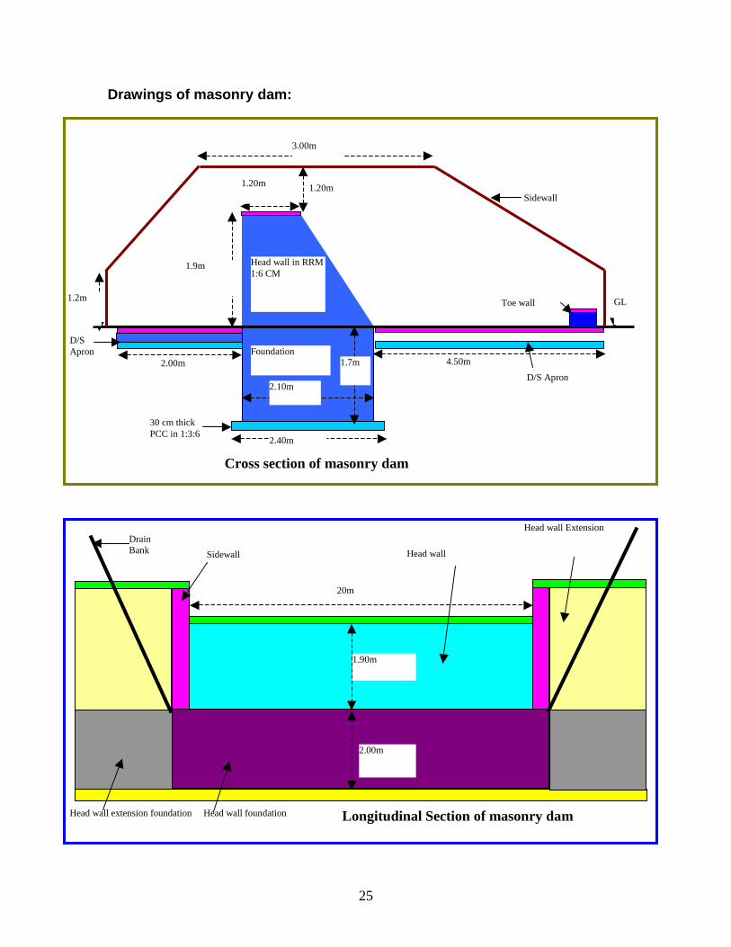
Drawings of masonry dam:
1.20m
2.00m
3.00m
1.2m
1.9m
4.50m
2.10m
2.40m
D/S Apron
Sidewall
D/S Apron
30 cm thick PCC in 1:3:6
Head wall in RRM 1:6 CM
Foundation
GL
1.20m
1.7m
Cross section of masonry dam
Toe wall
20m
2.00m
Longitudinal Section of masonry dam
1.90m
Drain Bank Head wall Sidewall
Head wall Extension
Head wall extension foundation Head wall foundation

26
2.0M
1.2 M
2.1M
4.5M
U/S Apron
D/S Apron
Head Wall Bottom width
Head wall top width
Toe wall
Earthen Dam Earthen
Dam
Wing wall Sidewall
Head wall
Exten.
Plan of Stone masonry dam
5.23m
3.1m
0.5m
1.3m
1.5m
Cross section of Side wall and Wing wall
GL
27
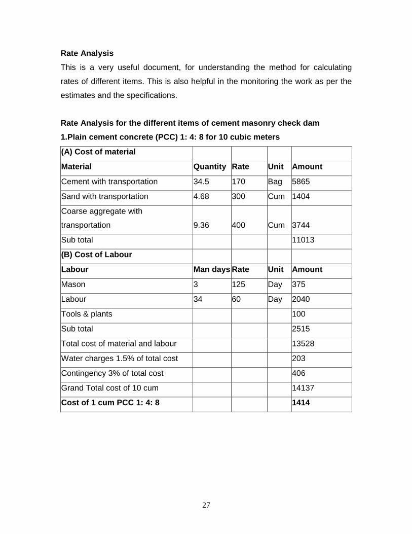
Rate Analysis
This is a very useful document, for understanding the method for calculating
rates of different items. This is also helpful in the monitoring the work as per the
estimates and the specifications.
Rate Analysis for the different items of cement mas onry check dam
1.Plain cement concrete (PCC) 1: 4: 8 for 10 cubic meters
(A) Cost of material
Material Quantity Rate Unit Amount
Cement with transportation 34.5 170 Bag 5865
Sand with transportation 4.68 300 Cum 1404
Coarse aggregate with
transportation 9.36 400 Cum 3744
Sub total 11013
(B) Cost of Labour
Labour Man days Rate Unit Amount
Mason 3 125 Day 375
Labour 34 60 Day 2040
Tools & plants 100
Sub total 2515
Total cost of material and labour 13528
Water charges 1.5% of total cost 203
Contingency 3% of total cost 406
Grand Total cost of 10 cum 14137
Cost of 1 cum PCC 1: 4: 8 1414
28
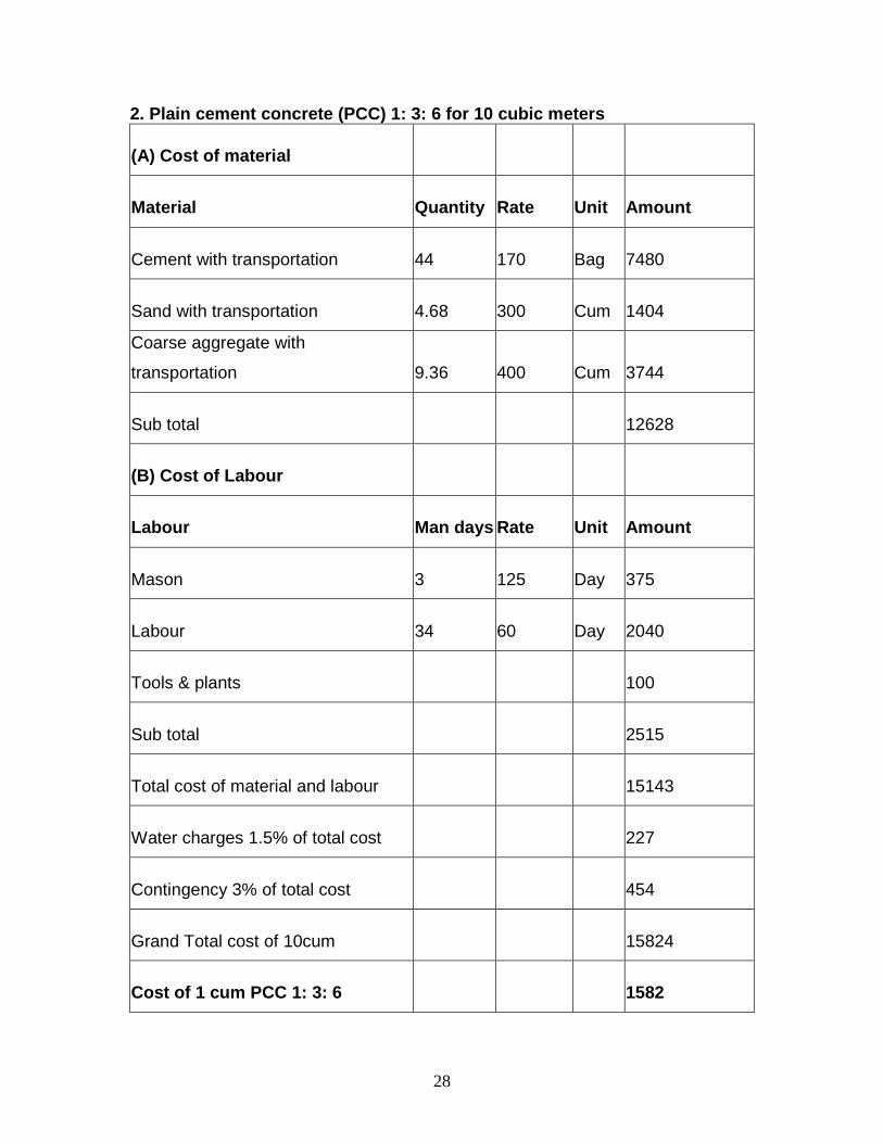
2. Plain cement concrete (PCC) 1: 3: 6 for 10 cubic meters
(A) Cost of material
Material Quantity Rate Unit Amount
Cement with transportation 44 170 Bag 7480
Sand with transportation 4.68 300 Cum 1404
Coarse aggregate with
transportation 9.36 400 Cum 3744
Sub total 12628
(B) Cost of Labour
Labour Man days Rate Unit Amount
Mason 3 125 Day 375
Labour 34 60 Day 2040
Tools & plants 100
Sub total 2515
Total cost of material and labour 15143
Water charges 1.5% of total cost 227
Contingency 3% of total cost 454
Grand Total cost of 10cum 15824
Cost of 1 cum PCC 1: 3: 6 1582

29
3. Plain cement concrete (PCC) 1: 2: 4 for 10 cubic meters
(A) Cost of material
Material Quantity Rate Unit Amount
Cement with transportation 64 170 Bag 10880
Sand with transportation 4.68 300 Cum 1404
Coarse aggregate with
transportation 9.36 400 Cum 3744
Sub total 16028
(B) Cost of Labour
Labour Man days Rate Unit Amount
Mason 3 125 Day 375
Labour 34 60 Day 2040
Tools & plants 100
Sub total 2515
Total cost of material and labour 18543
Water charges 1.5% of total cost 278
Contingency 3% of total cost 556
Grand Total cost of 10cum 19377
Cost of 1 cum PCC 1: 2: 4 1938

30
4. Plaster 20mm thick 1: 4 cement mortar for 100 sq m
(A) Cost of material
Material Quantity Rate Unit Amount
Cement with transportation 19 170 Bag 3230
Sand with transportation 2.6 300 Cum 780
Sub total 4010
(B) Cost of Labour
Labour Man days Rate Unit Amount
Mason 12 125 Day 1500
Labour 18 60 Day 1080
Tools & plants 100
Sub total 2680
Total cost of material and labour 6690
Water charges 1.5% of total cost 100
Contingency 3% of total cost 201
Grand Total cost of 100 sqm. 6991
Cost of 1 sqm plaster 1: 4 cement
mortar 70

31
5. Plaster 20 mm thick 1: 6 cement mortar for 100 s qm
(A) Cost of material
Material Quantity Rate Unit Amount
Cement with transportation 13.65 170 Bag 2321
Sand with transportation 2.8 300 Cum 840
Sub total 3161
(B) Cost of Labour
Labour Man days Rate Unit Amount
Mason 12 125 Day 1500
Labour 18 60 Day 1080
Tools & plants 100
Sub total 2680
Total cost of material and labour 5841
Water charges 1.5% of total cost 88
Contingency 3% of total cost 175
Grand total cost of 100 sqm. 6103
Cost of 1 sqm plaster 1: 6 cement
mortar Rs. 61
32
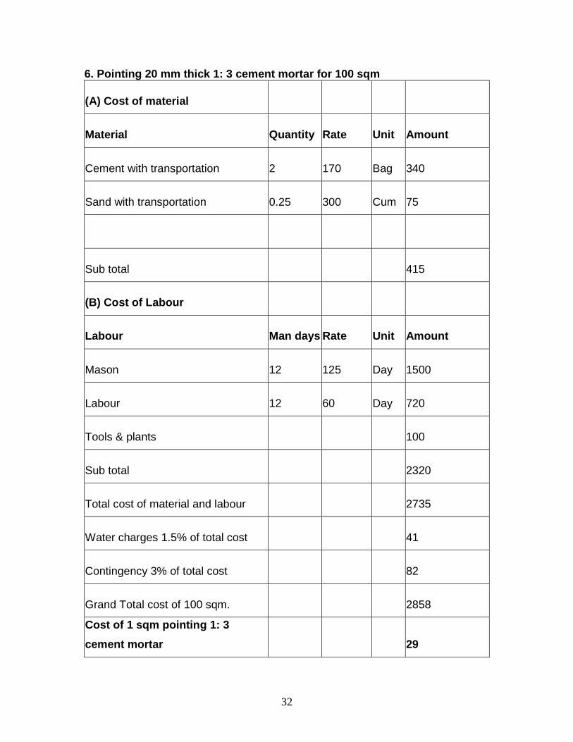
6. Pointing 20 mm thick 1: 3 cement mortar for 100 sqm
(A) Cost of material
Material Quantity Rate Unit Amount
Cement with transportation 2 170 Bag 340
Sand with transportation 0.25 300 Cum 75
Sub total 415
(B) Cost of Labour
Labour Man days Rate Unit Amount
Mason 12 125 Day 1500
Labour 12 60 Day 720
Tools & plants 100
Sub total 2320
Total cost of material and labour 2735
Water charges 1.5% of total cost 41
Contingency 3% of total cost 82
Grand Total cost of 100 sqm. 2858
Cost of 1 sqm pointing 1: 3
cement mortar 29

33
7. Random rubble masonry 1: 4 cement mortar for 10 cum
(A) Cost of material
Material Quantity Rate Unit Amount
Cement with transportation 23.5 170 Bag 3995
Sand with transportation 3.2 300 Cum 960
Dressed Stone with transportation 12.5 400 Cum 5000
Sub total 9955
(B) Cost of labour
Labour Man days Rate Unit Amount
Mason 16 125 Day 2000
Labour 26 60 Day 1560
Tools & plants 100
Sub total 3660
Total cost of material and labour 13615
Water charges 1.5% of total cost 204
Contingency 3% of total cost 408
Grand Total cost of 10 cum. 14228
Cost of 1 cum stone masonry 1: 4
cement mortar 1423

34
8. Random rubble masonry 1: 6 cement mortar for 10 cum
(A) Cost of material
Material Quantity Rate Unit Amount
Cement with transportation 16.8 170 Bag 2856
Sand with transportation 3.4 300 Cum 1020
Dressed stone with transportation 12.5 400 Cum 5000
Sub total 8876
(B) Cost of Labour
Labour Man days Rate Unit Amount
Mason 16 125 Day 2000
Labour 26 60 Day 1560
Tools & plants 100
Sub total 3660
Total cost of material and labour 12536
Water charges 1.5% of total cost 188
Contingency 3% of total cost 376
Grand Total cost of 10 cum. 13100
Cost of 1 cum stone masonry 1:6
CM 1310