planar multibeam antenna for wlan applications -...
TRANSCRIPT

Planar Multibeam Antenna for WLAN Applications
Final Project Work for the degree of Bachelor of Science in Computer Science and Communications Engineering.
By Kodua Watson Acheampong (747513) September 2006,Uni Duisburg-Essen.
Chapter One: Introduction
• Antenna defined: An Antenna is a device used to transform an RF signal, travelling on a conductor, into an EM wave in free space.
• How an antenna radiates: An antenna's ability to radiate is explained with the help of the next slide.


Antenna Classification
• Antennas can be classified according to:
3. Frequency and Size Antennas used for high frequency (HF) are
different from those used for very high frequency (VHF) applications.
The wavelength is different at different frequencies, so the antennas must be different in size to radiate signals at the correct wavelength.

Classification based on directivity
• Antennas can be Omnidirectional; that is, the ability of an antenna to radiate the same pattern all around the antenna in a complete 360° pattern.
• Antennas can also be Sectorial; thus the radiated beam is focused primarily into a specific area. The beam could be as much as 180° wide or as narrow as 60° in width.
• Antennas can also be described as being Directive. This refers to the class of antennas with beamwidth much narrower than sectorial antennas.

Antennas for WLAN Applications
• Classifying antennas for WLAN use could be based on application, thus;
2. Base station antenna3. Point-to-Point antenna This Project focuses on Base station
antennas, and to be specific, Adaptive base station antennas, which are designed to improve the SNIR in terrestrial mobile communications.

Switched Beam Antennas• Among the different techniques of
implementing an adaptive antenna system, i.e., Beamforming, Switched Beam, and Adaptive Arrays, the Switched Beam antenna system serves the purpose of this project.
• Typical implementation is based on Butler matrix which provides one orthogonal beam per antenna element.

Chapter Two:Microstrip Antennas
• Microstrip antennas are used to build the linear antenna array used in the switched beam antenna system.
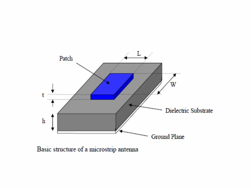
• A microstrip antenna is made up of a radiating patch on one side of a dielectric substrate which has a ground plane metal on the other side as shown in the next slide.

Advantages and Disadvantages of the Microstrip Antenna
• Advantages:• Low weight, low volume, and thin profile configurations.• Low fabrication cost.• Feed lines and matching networks can be fabricated
simultaneously with the antenna structure, etc• Disadvantages:• Narrow bandwidth and associated tolerance problems• Large ohmic loss in the feed structure of arrays• Complex feed structures required for high performance
arrays• Lower Power handling capacity • Excitation of surface waves, etc

Feed TechniquesAmong the numerous feed techniques formicrostrip antennas are;• The microstrip line inset feed • The coaxial probe feed• The Aperture coupled feed • The Proximity coupled feed All the above mentioned feed techniques have
their inherent advantages and disadvantages, leading us to the choice of the microstrip line feed mechanism.

Characteristics of feed techniques

Microstrip line excitation• Below is a diagram showing a microstrip line fed
patch antenna.

Models for Analysis• Various analytical and numerical methods exist
for the analysis of the microstrip antenna such as; the transmission line model, the cavity model, the multi-port model-analytical methods
• The finite difference time domain model, integral equation analysis in the spectral domain, and integral equation in the time domain are examples of numerical methods of analysis.
• The transmission line model is considered and applied for predicting the physical dimensions of our microstrip antenna in this project.

The Transmission line model• The transmission line model represents the microstrip antenna as
two slots of width W, height h, separated by length L.• An expression for the effective length of the half-wavelength patch
antenna is given as;

Transmission line model • εreff is the effective dielectric constant which account for
the fringing fields that occur as a result of the fraction of the electric field lying outside the physical dimensions L*W of the patch element.
• An expression for the effective dielectric constant is given as:

Transmission line model• The actual physical length, L is calculated from
the following expression, with ΔL accounting for the fringing field effect along the length L

Transmission line model• An expression for ΔL is given below.

Transmission line Model
• An expression for the width is also given as follows;

Chapter three: Single Element Patch Antenna and Simulation
• Based on the transmission line model, specific physical dimensions of the patch antenna is calculated.
• The fabrication of the entire antenna system is to be carried out on a rogers RO4003 substrate of thickness, h= 0.52mm, dielectric constant, εr = 3.38, electric loss tangent, tanδ = 0.0027.
• Inserting these values in the appropriate equations displayed before, we obtain the following values for the patch antenna:
• Length, L = 32.541mm• Width, W = 40.544mm
Introduction to Simulation Software HFSS
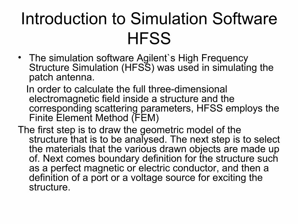
• The simulation software Agilent`s High Frequency Structure Simulation (HFSS) was used in simulating the patch antenna.
In order to calculate the full three-dimensional electromagnetic field inside a structure and the corresponding scattering parameters, HFSS employs the Finite Element Method (FEM)
The first step is to draw the geometric model of the structure that is to be analysed. The next step is to select the materials that the various drawn objects are made up of. Next comes boundary definition for the structure such as a perfect magnetic or electric conductor, and then a definition of a port or a voltage source for exciting the structure.

Simulation Software HFSS• A complete modelling of the structure would
include definition of range of frequencies over which the simulation is to be performed, the frequency at which an adaptive mesh refinement takes place and the convergence criterion.
• After all the above mentioned procedures are carried out, the simulation can be run.
• The solution data is post processed after which information such as s-parameter plots, impedance plots, far-field plots and the like.

Simulation Software HFSS
The patch element with inset length for impedance matching is shown in the next slide.
With a suitable length of the microstrip line inserted into the patch element, impedance matching could be obtained as depicted in the diagram.
This is one of the advantages of a microstrip line inset-fed patch antenna.

Simulation Software HFSS

Simulation Software HFSS
• Determining yo tells us how much we should inset the microstrip line to obtained an input impedance match, in this case, 50Ω.
• An estimate formula for calculating yo is;

Simulation Software HFSS
S-Parameter
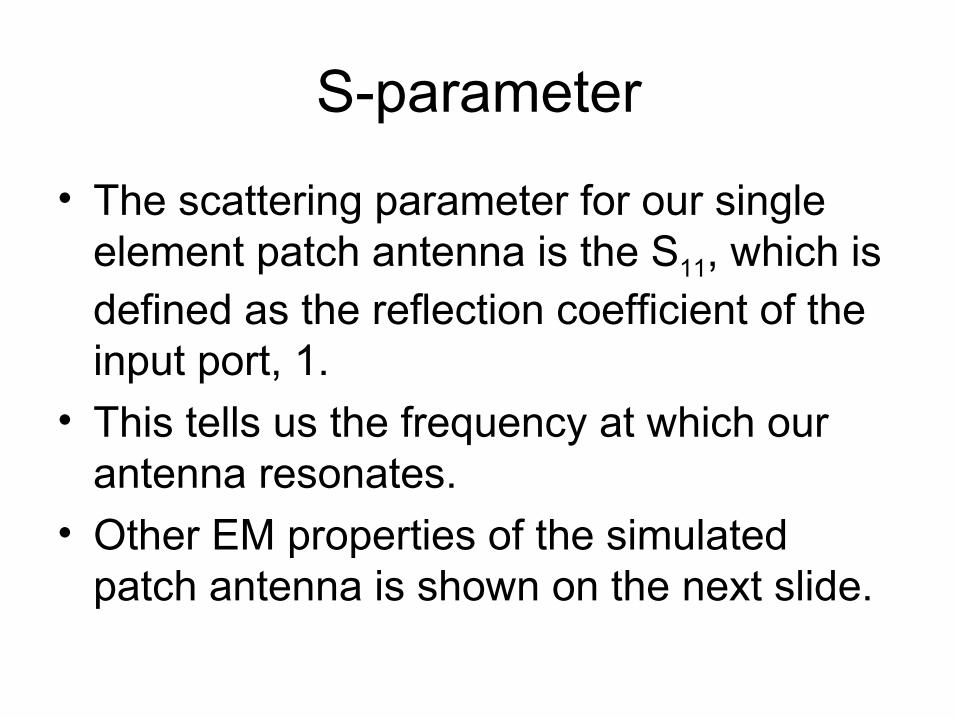
S-parameter
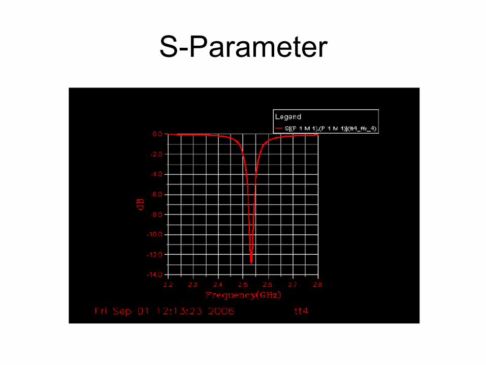
• The scattering parameter for our single element patch antenna is the S11, which is defined as the reflection coefficient of the input port, 1.
• This tells us the frequency at which our antenna resonates.
• Other EM properties of the simulated patch antenna is shown on the next slide.

Antenna parameters

Beam forming techniques
• Among fixed beam forming techniques are;
• The Butler Matrix• The Blass Matrix• The Wullenweber ArrayOf interest to us is the Butler matrix which
happens to be the feed network employed in this project.

Butler Matrix
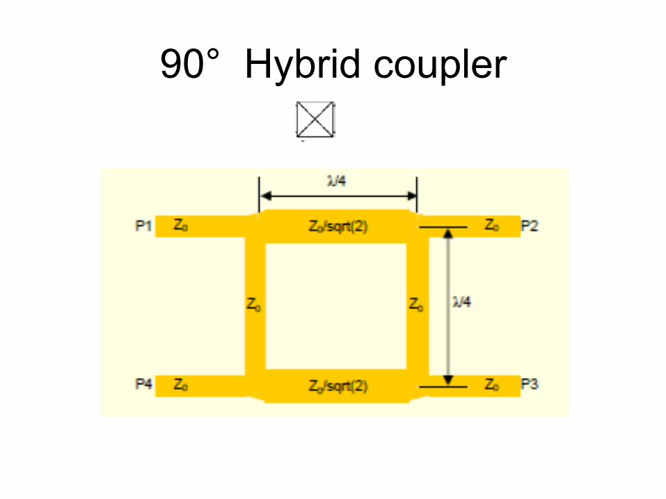
90° Hybrid coupler
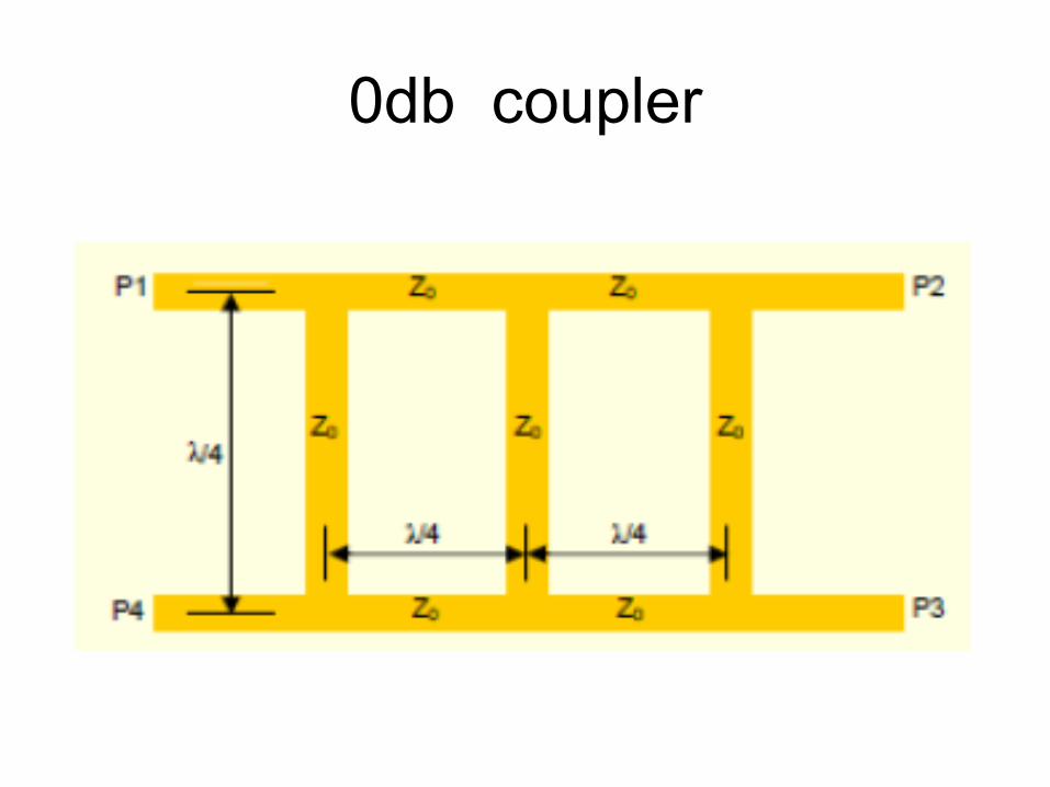
0db coupler

Linear antenna array