placing booms 2014 - alfatekturk.com.tr
TRANSCRIPT

SEPARATE PLACING BOOMS SPB

SCHWING GMBH – Separate Placing Booms SPB 02/2014
1
Index of Contents:
Method statement - highrise ............................ Fehler! Textmarke nicht definiert.
1 Stationary Placing Boom: ................................................................................. 2
1.1 General ..................................................................................................... 2
1.2 Installation method .................................................................................... 3
1.3 Technical data and options ....................................................................... 4
1.3.1 SPB 25 (Split boom)............................................................................. 5
1.3.2 SPB 28 (Split boom)............................................................................. 5
1.3.3 SPB 32 (Split boom)............................................................................. 5
1.3.4 SPB 35 (Split boom)............................................................................. 6
1.3.5 Accessories ......................................................................................... 6
1.4 Climbing procedure ................................................................................... 8
1.5 Assembly instructions ............................................................................. 12
1.5.1 General points to consider when using placing booms ....................... 12
1.5.2 Safety aspects ................................................................................... 13
1.5.3 TOOLS REQUIRED FOR ASSEMBLY .............................................. 15
1.6 Working range ......................................................................................... 16
1.6.1 SPB 25 ............................................................................................... 16
1.6.2 SPB 28 ............................................................................................... 17
1.6.3 SPB 32 ............................................................................................... 18
1.6.4 SPB 35 ............................................................................................... 19
1.7 Examples for load drawings .................................................................... 20
1.7.1 SPB 25 in slab distance 3m (no counterweight) ................................. 21
1.7.2 SPB 28 freestandig with 18m column (no counterweight) .................. 22
1.7.3 SPB 28 freestandig with 18m column (with counterweight) ................ 23
1.7.4 SPB 28 in slab distance 3,2m (no counterweight) .............................. 24
1.7.5 SPB 32 in slab distance 4,0m (no counterweight) .............................. 25
1.7.6 SPB 35 in slab distance 4,5m (no counterweight) .............................. 26

SCHWING GMBH – Separate Placing Booms SPB 02/2014
2
1 Stationary Placing Boom: 1.1 General
The limits of concrete placement continuously expand with the application of a Schwing concrete pump and placing boom combination. Now imagine where you want the concrete to be placed...at what rate... and let the Schwing product specialists plan a distribution system with the site manager. The possibilities are endless with the various booms sizes available, the mounting options and the number and sizes of booms that can be engineered into a project. The net result is systematic concrete placement you can count on while increasing placement rates by as much as 50-percent over other methods. Labour requirements are minimal – one person operates the placing boom for uniform concrete placement in wall, column and deck forms – less raking and finishing time is required because of the precise placement. Continuous flow also results in higher quality concrete. Added time savings are realized by the tower crane being free to handle other lifting operations. Years ago already the trend to rationalization and short completion periods led to the use of placing booms for the construction of large-scale buildings. Based on the experience in the manufacture of concrete placing equipment, SCHWING was able to offer their trendsetting equipment at a very early stage. As far back as in 1969 where the first SCHWING separate placing boom was put into operation by Ph. Holzmann in the joint venture Asenwald Stuttgart. The experience gained through all these years on a great number of construction sites all over the world enabled SCHWING consulting engineers gain the experience to offer the optimum concrete placing method for every site. One way to place concrete quickly and economically is the use of separate placing booms in conjunction with efficient concrete pumps. The placing booms with the designation SPB and those of truck-mounted concrete pumps are of equal design. That is why the placing booms SPB 30 through SPB 35 can be used for stationary as well as on truck mounted pumps.

SCHWING GMBH – Separate Placing Booms SPB 02/2014
3
1.2 Installation method
Free standing up to 20 m
Through the floor slabs
Directly on cross frame

SCHWING GMBH – Separate Placing Booms SPB 02/2014
4
1.3 Technical data and options Boom of stable box-type construction, 4-stage hydraulic folding in vertical plane with attached pipeline, pivoted on a swivelling slewing column, operation of the boom by means of hand levers or installed electric remote control cable, end hose and connecting line for connection to the delivery pipeline. Trestle-pin connection for quick separation when repositioning the placing boom. First boom section with pin joint. Powering of the hydraulic pump for hydraulic actuation of all boom movements is made by an electric motor. The complete power unit including the hydraulic tank and control box is installed near the pedestal.

SCHWING GMBH – Separate Placing Booms SPB 02/2014
5
1.3.1 SPB 25 (Split boom)
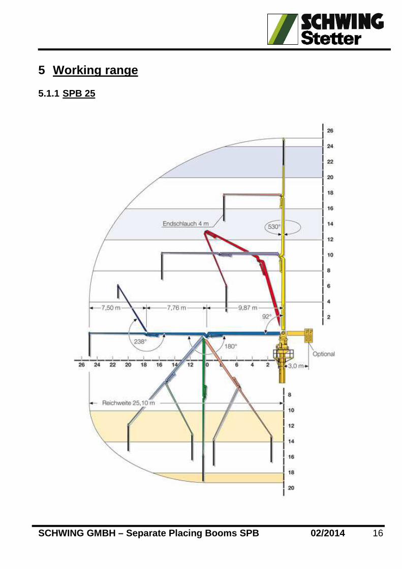
Technical data Dia. of pipeline DN 125 Horizontal reach from centre of rotating axis, max. 25 m Slewing range folding 530° Length of end hose 4 m Electric engine power 400 V, 50 cps, protection mode IP 44 22 kW Total weight of the boom 5970 Kg with hydraulic oil, with pin connection on main boom to reduce handling weight.
1.3.2 SPB 28 (Split boom) Technical data
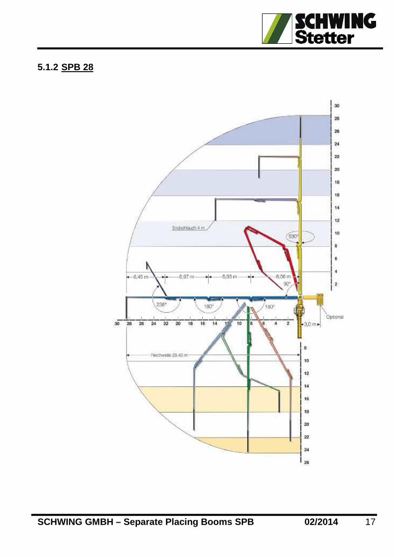
Dia. of pipeline DN 125 Horizontal reach from centre of rotating axis, max. 28 m Slewing range folding 530° Length of end hose 4 m Electric engine power 400 V, 50 cps, protection mode IP 44 30 kW Total weight of the boom 6380 Kg with hydraulic oil, with pin connection on main boom to reduce handling weight. 1.3.3 SPB 32 (Split boom) Technical data
Dia. of pipeline DN 125 Horizontal reach from centre of rotating axis, max. 30 m Slewing range folding 530° Length of end hose 4 m Electric engine power 400 V, 50 cps, protection mode IP 44 30 kW Total weight of the boom 7100 Kg with hydraulic oil, with pin connection on main boom to reduce handling weight.

SCHWING GMBH – Separate Placing Booms SPB 02/2014
6
1.3.4 SPB 35 (Split boom) Technical data
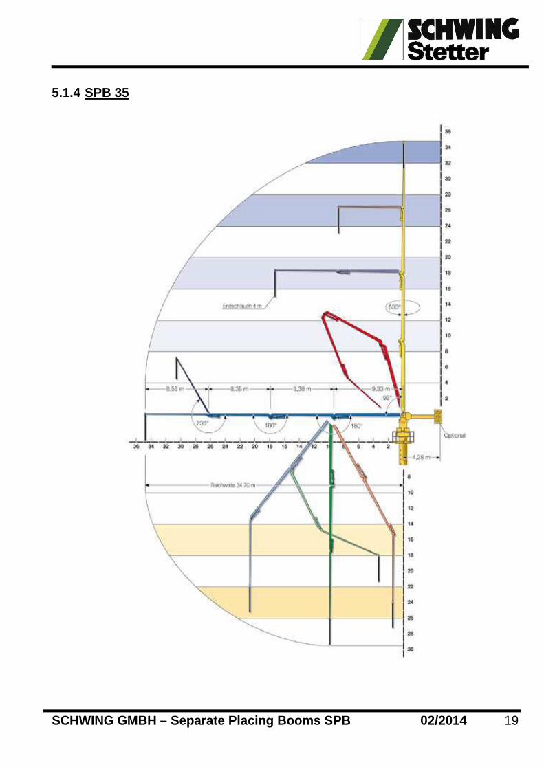
Dia. of pipeline DN 125 Horizontal reach from centre of rotating axis, max. 35 m Slewing range folding 530° Length of end hose 4 m Electric engine power 400 V, 50 cps, protection mode IP 44 30 kW Total weight of the boom 8350 Kg with hydraulic oil, with pin connection on main boom to reduce handling weight.
2 Accessories Supplemental Equipment for Concrete Placing Boom 1x Tubular head part (638 Kg for SPB 28 and 32 / 8 49 Kg for SPB 35) 2m with integrated flanges.
3x Tubular segments ( 1450 Kg each segment)
Consisting of 3 segments each 6m Octagunal column
Total height: approx. 20 m
With the following methods of fixture:
A: Free standing
20 m max. on cross frame
B: Climbing through a building :
with openings of about 1045 mm X 1045 mm in each floor.

SCHWING GMBH – Separate Placing Booms SPB 02/2014
7
To be fixed 2-3 floors slabs (depending on the floor height) to ensure the
requested stability. The boom can be mounted on a 20 m column inside the
building with a max. free standing height of 15 m above the last floor frame .
1x Hydraulic climbing device (75 Kg each cylinder)
for automatic lifting of the tubular mast and placing boom, consisting of:
1 set climbing cylinders actuated by means of a hand lever at the control block or via remote control - push button and approx. 15 m cable, suspensions with socket pins.
3x floor frames (272 Kg each) with 2 each eccentric pins and guide rollers, 2 small cross bolt + 8 wedges
1x Cross frame (755 Kg)
SCHWING GMBH – Separate Placing Booms SPB 02/2014
8
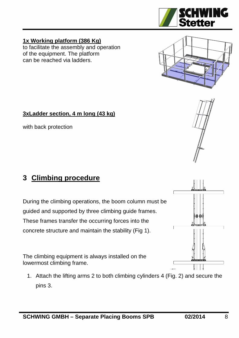
1x Working platform (386 Kg) to facilitate the assembly and operation of the equipment. The platform can be reached via ladders.
3xLadder section, 4 m long (43 kg)
with back protection
3 Climbing procedure
During the climbing operations, the boom column must be
guided and supported by three climbing guide frames.
These frames transfer the occurring forces into the
concrete structure and maintain the stability (Fig 1).
The climbing equipment is always installed on the lowermost climbing frame.
1. Attach the lifting arms 2 to both climbing cylinders 4 (Fig. 2) and secure the
pins 3.

SCHWING GMBH – Separate Placing Booms SPB 02/2014
9
2. Place the climbing cylinders on the supports of
the lowermost guide frame (Fig. 1), insert the
lifting pins 1 in position "A" and secure. In this
position, the climbing cylinders can be
extended and retracted without the boom
column being lifted (for bleeding).
3. Extend the climbing cylinders slowly to the
limit top. The boom column and the placing
boom are raised in the process.
4. When the climbing cylinders are fully extended, insert a supporting pin 1 (Fig.
2) on both sides above the guide frame.
5. The safety latches 2 (Fig. 2) of the supporting pins
must be inserted into the next higher bore of the
boom column − Relieve the climbing cylinders by
retracting them slowly a short distance. The load of
the boom column and the placing boom is now
borne by the supporting pins.
6. Retract the climbing cylinders completely (Fig. 3).
7. Withdraw the lifting pins and insert into the
next hole (Fig. 3).
8. The next lifting procedure can now be started.
9. Repeat these steps until the boom column has
reached the desired height.

SCHWING GMBH – Separate Placing Booms SPB 02/2014
10
Attention:
To maintain stability, the boom column may be
raised only to such an extent that its lower edge
is still 1.50 m away from the lower most climbing guide frame (Fig. 1).
RISK OF ACCIDENT
The boom column and the placing boom may topple ove r.
Lift the boom column out of the lowermost guide fra me only after having
installed a third climbing guide frame at the top.
When this position is reached, the climbing equipment and the climbing guide
frame must be relocated (Fig. 1) if climbing is to
continue.
To do so:
− Move the climbing equipment to the next higher
floor and install
− Dismantle the lowermost climbing guide frame
and move it up to the highest floor. Refit the frame
there.
− When the desired height is reached, secure the
boom column with wedges. To secure, drive eight
wedges 1 (Fig. 1 and Fig. 2) into the guides of the
upper frame and eight wedges into the guides of
the lower frame (arrows, Fig. 1).
Attention:
For static reasons, no wedges must be
driven in at the middle guide frame.

SCHWING GMBH – Separate Placing Booms SPB 02/2014
11

SCHWING GMBH – Separate Placing Booms SPB 02/2014
12
4 Assembly instructions The information contained in this document is an ai d only and in no way replaces the operation instructions and safety manu als. 4.1.1 General points to consider when using placing booms
1. The placing boom is used on a site to relieve the crane from concreting
operations.
2. Consideration must be given to the time the installation of the boom requires.
3. Full supervision must be given during the operations; the supervisor must be
experienced in the task.
4. Full and complete check systems need to be used to monitor the installation
and commissioning of the machine.
5. Operators must be trained to maintain the equipment to a reasonable standard.
6. Attention must be paid to the condition of the machine while on site, it must be
inspected regularly by a competent person and a report placed in the safety file.
7. The site electrician should inspect, on a regular basis, the power cable and
installed sockets, at both the control panel on the boom and the circuit breaker
at the mains supply.
8. If the boom is to be used on its own generator, the recommended size to use is
75kVA.
9. On a SPB32 placing boom, the 22kW electric motor requires a start up current
of 84 Amps and a running current of 42 Amps.
10. Safety is paramount and to this end all assembly personnel need to be trained
and certified in the safe and correct installation of placing booms.
11. Cleaning out of the boom should be considered and the use of the water wash
out system is recommended. This is cost effective and the concrete in the line is
pumped to the placing point and with continued practice this system is safer.

SCHWING GMBH – Separate Placing Booms SPB 02/2014
13
4.1.2 Safety aspects
When assembling the Schwing separate placing boom system on the octagonal
column accessories, it needs to be recognised that although the system is
designed to be simple to use, the components are of a robust construction and as
such are heavy to handle. A dedicated crane is required for the initial installation.
When these operations are carried out on a site all of the site management needs
to be made aware of the cranes intensive use during the erection.
A banks man must be with the assembly team at all times. It must be realised that
for ease of assembly all the components must be slung level, trying to force the
items together is tiring, awkward and with the close proximity of operatives’ hands
to the connection points, failure to sling items correctly will create a hazard.
The working area needs to be properly cordoned off and clear of any trip hazards.
It needs to be of sufficient size to allow ease of access and egress for the
assembly personnel.
Every operative must wear the required PPE and safety harnesses and fall arrest
equipment must be supplied to those who will be climbing the mast to carry out
final connection.
Precaution should be taken regarding tools that have to be used on the working
platform of the mast, the ladders have safety hoops attached restricting the
person on the ladder from being able to carry any bulky items.
A simple idea is to have rope hanging from the working platform hand rail, (this
should only be during installation) and a tool bag that can be closed, hence the
tools once in the bag are then fastened to the rope and hoisted to the work area.
When used with a heavy duty cross frame, the holding down bolts must be M36
diameter and of 8.8 grade. Schwing can give the correct tensile and compressive
loads and it is then up to the bolt supplier to give the correct torque settings for
these bolts.

SCHWING GMBH – Separate Placing Booms SPB 02/2014
14
The construction bolts in the mast section, are M36 x 360 cap screws and be of
10.9 grade. The torque for these bolts is according to drawing No.10216625.
Correct pipe clamps are to be used to attach the delivery line and plastic support
plates are also required where the delivery line is attached to the ladder brackets.
Safety clips must be fitted to all pipe clamps and where required “R” clips must be
in place (such as the working platform mounting points).
To join the column sections together, initially the “Top” section of mast has to be
“packed up” level and the next section suspended from the crane, for this
operation some form of support, of sufficient capacity, is required.
Total lifting weight of the column assembly complete with 3 No. 6m sections, top
section, working platform, ladders with back rests and the concrete delivery
pipeline is approximately 5,500 kg. A crane of sufficient capacity is required for the
operation of lifting the column on top of the heavy duty cross frame.
Otherwise, the column must be assembled on top of the heavy duty cross frame,
one piece at a time. For this method of assembly, a form of access platform is
required for the assembly operatives to work safely at 6m, 14, and at 20m height.
The total lifting weight of the boom assembly is 6,400 kg and if the site does not
have the tower crane, which could not lift the boom in one piece, it can be split
into "turret section" and "boom packet". The weights of the split sections are
2,600kg and 3,800 kg respectively.
THE OPERATION OF INSTALLING A “SCHWING” PLACING BOO M
REQUIRES THE CRANE TO BE MADE AVAILABLE WHEN THE AS SEMBLY
TEAM IS READY TO CARRY OUT THE INDIVIDUAL OPERATION S.
TRYING TO CARRY ON WITH NORMAL SITE MOVEMENTS AND “ FIT IN”
THE TASKS REQUIRED FOR ASSEMBLY, NOT ONLY LEADS TO DELAYED
AVAILABILITY OF THE BOOM, BUT ALSO THE POSSIBILITY OF MISTAKES
OCCURING BECAUSE OF LONG DELAYS BETWEEN OPERATIONS.

SCHWING GMBH – Separate Placing Booms SPB 02/2014
15
4.1.3 TOOLS REQUIRED FOR ASSEMBLY
VARIATIONS / COMBINATIONS OF SPANNERS, RATCHETS AND AIR
POWERED TOOLS ARE REQUIRED.
1. NUT / BOLT HEAD SIZES ARE :-
- M27 ALLEN KEY FOR MAST CONSTRUCTION BOLTS.
- 36mm SPANNER OR SOCKET FOR THE NUTS.
- 24mm SPANNER FOR THE NUTS ON THE LADDER HOOPS AND THE
DELIVERY PIPE SUPPORT CLAMPS.
2. 17mm AND 19mm SPANNERS/ SOCKETS FOR THE FIXINGS ON THE
WORKING PLATFORM AND TRAP DOOR ASSEMBLY.
3. HAMMER FOR DRIVING IN / OUT THE CONNECTION PINS ON THE
BOOM TO MAST CONNECTION OR THE BOOM ARM TO TURRET
CONNECTION.
4. HYDRAULIC TORQUE WRENCH TO TORQUE THE CONSTRUCTION
BOLTS HOLDING THE FLANGES OF THE MAST SECTIONS.
5. PAINT BRUSH FOR APPLYING GREASE TO CONNECTION PINS/
POINTS.
6. 55mm SOCKET/ SPANNER FOR NUTS ON HOLDING DOWN BOLTS.
THIS LIST IS FOR USE ONLY AS A GUIDELINE AND IS BAS ED ON THE
FIXINGS PROVIDED WITH “SCHWING” STANDARD SCOPE OF S UPPLY. IF
OTHER SUPPLIERS OF FIXINGS HAVE BEEN USED SEEK THEI R ADVICE
ASTO TOOL REQUIREMENTS.
SCHWING GMBH – Separate Placing Booms SPB 02/2014
16
5 Working range 5.1.1 SPB 25
SCHWING GMBH – Separate Placing Booms SPB 02/2014
17
5.1.2 SPB 28

SCHWING GMBH – Separate Placing Booms SPB 02/2014
18
5.1.3 SPB 32
SCHWING GMBH – Separate Placing Booms SPB 02/2014
19
5.1.4 SPB 35

SCHWING GMBH – Separate Placing Booms SPB 02/2014
20
6 Examples for load drawings Please note that in case of other dimensions on site, new Load calculations have to be made and adapted to the real situation on site.

SCHWING GMBH – Separate Placing Booms SPB 02/2014
21
6.1.1 SPB 25 in slab distance 3m (no counterweight)

SCHWING GMBH – Separate Placing Booms SPB 02/2014
22
6.1.2 SPB 28 freestandig with 18m column (no counte rweight)

SCHWING GMBH – Separate Placing Booms SPB 02/2014
23
6.1.3 SPB 28 freestandig with 18m column (with coun terweight)

SCHWING GMBH – Separate Placing Booms SPB 02/2014
24
6.1.4 SPB 28 in slab distance 3,2m (no counterweigh t)

SCHWING GMBH – Separate Placing Booms SPB 02/2014
25
6.1.5 SPB 32 in slab distance 4,0m (no counterweigh t)

SCHWING GMBH – Separate Placing Booms SPB 02/2014
26
6.1.6 SPB 35 in slab distance 4,5m (no counterweigh t)

SCHWING GMBH – Separate Placing Booms SPB 02/2014
27
Solutions for concrete