pl30-1212 12/17/2015 12-12 series - penn tool co. - penn...
TRANSCRIPT

For additional product information visit our website at http://www.apextoolgroup.com
Parts Manual45-8213ENPL30-121212/17/2015
12-12 SeriesRight Angle Grinder, Sander, and Router

Page 2
45-8213EN12/17/2015
12 X 1 2 XX - XX XX XX OH
Product Classification12 = Ergo Grinder/Sander
Throttle TypeL = Locking LeverS = Locking Lever (same configuration as "L")
Motor Size1 = 0.3 Horsepower
Tool Style2 = Right Angle
Speed Options (RPM)Front Exhaust Rear Exhaust
00 = 12,000 80 = 12,00001 = 20,000 81 = 20,000
Primary Termination Code27 = 3/8"-24 External Thread Spindle (Type 1 Cutoff Wheels)32 = 1/4"-28 Internal Thread Spindle34 = 5/16"-24 Internal Thread Spindle35 = 3/8"-24 Internal Thread Spindle36 = 300 Series, 1/4" (3 piece) Collet45 = 1/4" Universal Collet Spindle
Extended Termination CodeB1 = Belt Sander (1/4" x 12")B2 = Belt Sander (1/2" x 12")B3 = Belt Sander (1/2" x 24")B4 = Belt Sander (1" x 12")B5 = Belt Sander (1" x 24")RT = Router
OptionsOptinal Collets
LH = Left Hand Rotation Motor
Overhose Option (extra cost)OH = Exhaust Overhose (Rear exhaust models only)
Dotco®
Nomenclature
Page 3
45-8213EN12/17/2015
Dotco®
Product Information
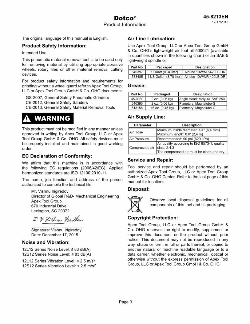
The original language of this manual is English.
Product Safety Information:Intended Use:This pneumatic material removal tool is to be used only for removing material by utilizing appropriate abrasive wheels, rotary files or other material removal cutting devices.For product safety information and requirements for grinding without a wheel guard refer to Apex Tool Group, LLC or Apex Tool Group GmbH & Co. OHG documents:
GS-2007, General Safety Pneumatic GrindersCE-2012, General Safety SandersCE-2013, General Safety Material Removal Tools
This product must not be modified in any manner unless approved in writing by Apex Tool Group, LLC or Apex Tool Group GmbH & Co. OHG. All safety devices must be properly installed and maintained in good working order.
EC Declaration of Conformity:We affirm that this machine is in accordance with the following EC regulations (2006/42/EC). Applied harmonized standards are ISO 12100:2010-11.The name, job function and address of the person authorized to compile the technical file.
Mr. Vishnu IrigireddyDirector of Global R&D- Mechanical EngineeringApex Tool Group670 Industrial DriveLexington, SC 29072
_______________________Signature: Vishnu IrigireddyDate: December 17, 2015
Noise and Vibration:12L12 Series Noise Level: ≤ 83 dB(A)12S12 Series Noise Level: ≤ 83 dB(A)12L12 Series Vibration Level: < 2.5 m/s2
12S12 Series Vibration Level: < 2.5 m/s2
Air Line Lubrication:Use Apex Tool Group, LLC or Apex Tool Group GmbH & Co. OHG’s lightweight air tool oil 500021 (available in quantities shown in the following chart) or an SAE-5 lightweight spindle oil.
Grease:
Air Supply Line:
Service and Repair:Tool service and repair should be performed by an authorized Apex Tool Group, LLC or Apex Tool Group GmbH & Co. OHG Center. Refer to the last page of this manual for locations.
Disposal:
Observe local disposal guidelines for all components of this tool and its packaging.
Copyright Protection:Apex Tool Group, LLC or Apex Tool Group GmbH & Co. OHG reserves the right to modify, supplement or improve this document or the product without prior notice. This document may not be reproduced in any way, shape or form, in full or parts thereof, or copied to another natural or machine readable language or to a data carrier, whether electronic, mechanical, optical or otherwise without the express permission of Apex Tool Group, LLC or Apex Tool Group GmbH & Co. OHG
WARNING
Part No. Packaged Designation540397 1 Quart (0.94 liter) Airlube 10W/NR-420LB DR533485 1 US Gallon (3.78 liter) Airlube 10W/NR-420LB DR
Parameter Description
Air Hose Minimum inside diameter: 1/4" (6,4 mm)Maximum length: 8.0' (2,4 m)
Air Pressure Recommended: 90 psi (620 kPa)
Compressed airAir quality according to ISO 8573-1, qualityclass 2.4.3The compressed air must be clean and dry.
Part No. Packaged Designation45-0980 2 oz. (0.06 kg) Angle Head: Moly-XL SAE 250540395 2 oz. (0.06 kg) Planetary: Magnalube-G513156 16 oz. (0.45 kg) Planetary: Magnalube-G

Page 4
45-8213EN12/17/2015
Dotco®
Front Exhaust Motor Assembly
“A”
Off
2
Models12(-)120012)-)1201
3
4 5
9
11
10
14
15
6
7
12
13
17
8
16
23
20
24
22
18
19
18
21
26
1
27
28
25
Off
Off

Page 5
45-8213EN12/17/2015
Dotco®
Front Exhaust Motor Assembly
ENDescription
1 14-0851 1 Housing Wrench2 01-2505 1 1 Inlet Adapter3 01-2506 1 Exhaust Plug4 2965 1 3 O-Ring5 3036PT 1 3 O-Ring6 01-1046 1 3 Filter Disc7 01-1016 1 Filter Retainer8 1003PT 1 Rear Plate (includes 1 Ref.18) - Right Hand Rotation Models
2157PT 1 Rear Plate (includes 1 Ref.18) - Left Hand Rotation Models - Code "LH"9 01-2519 1 3 Valve Spring
10 01-2518 1 1 Valve11 01-2504 1 Valve Seat12 1042 1 1 Lever Pin13 01-1017 1 Push Rod14 01-1267 1 1 Lock-Off Lever Assembly15 01-1001 1 Motor Housing16 1002PT 1 Cylinder17 504PT 1 2 Ball Bearing18 1041 2 4 Pin19 1006PT 4 12 Rotor Blade
04-0031 1 Rotor Blade Kit (50 Blades)20 1017PT 1 Spacer21 1355 1 1 Shim Packet22 538PT 1 2 Ball Bearing23 1005S 1 Rotor24 1064PT 1 Front Plate (includes 1 Ref. 18) - Right Hand Rotation Models
1896PT 1 Front Plate (includes 1 Ref. 18) - Left Hand Rotation Models - Code "LH"25 01-1043 1 Lock Ring26 Table "A" 1 1 Pinion Gear27 01-1045 1 Lock Ring Sleeve28 01-1021 1 3 Muffler Felt
(#) Quantity(X) Recommended Spare Parts (quantity shown based on 1-5 tools in operation)
Illustration "A" - Front Exhaust Models
Ref Number # X
Table "A"Ref. Description # 12(-)1200 # 12(-)1201
26 Pinion 1 03-1066 1 1187

Page 6
45-8213EN12/17/2015
Page 6
“B”
Dotco®
Rear Exhaust Motor Assembly
Models12(-)128012(-)1281
Off
23
910
152
11
14
45
6
12
13
17
8
16
23
20
24
22
18
19
18
21
26
127
28
25
Off
Off
7
Models without Overhose
Models with Overhose

45-8213EN12/17/2015
Page 7
Dotco®
Rear Exhaust Motor Assembly
ENDescription
1 14-0851 1 Housing Wrench2 01-2505 1 1 Inlet Adapter (without Overhose)
01-1031 1 1 Inlet Adapter (Overhose Models)3 01-2520 1 1 Diffuser4 01-1046 1 3 Filter Disc5 01-1016 1 Filter Retainer6 01-1032 1 1 Muffler (Overhose Models)7 3036PT 1 3 O-Ring (Overhose Models)8 1003PT 1 Rear Plate (includes 1 Ref.18)9 01-2519 1 K2 Valve Spring
10 01-2518 1 1 Valve11 01-2504 1 Valve Seat12 1042 1 1 Lever Pin13 01-1017 1 Push Rod14 01-1267 1 1 Lock-Off Lever Assembly15 01-1001 1 Motor Housing16 1002PT 1 Cylinder17 504PT 1 K2 Ball Bearing18 1041 2 K2 Pin19 1006PT 4 K2 Rotor Blade
04-0031 1 Rotor Blade Kit (50 Blades)20 1017PT 1 Spacer21 1355 1 K2 Shim Packet22 538PT 1 K2 Ball Bearing23 1005S 1 Rotor24 1064PT 1 Front Plate (includes Ref. 18, qty. 1)25 01-1044 1 Lock Ring26 Table "B" 1 1 Pinion Gear27 01-1045 1 Lock Ring Sleeve28 01-1025 1 3 Seal
(#) Quantity(X) Recommended Spare Parts (quantity shown based on 1-5 tools in operation)
Illustration "B" - Rear Exhaust Models
Ref Number # X
Table "B"Ref. Description # 12(-)1280 # 12(-)1281
26 Pinion 1 03-1066 1 1187

Page 8
45-8213EN12/17/2015
“C”
Dotco®
Angle Head
1
5
3
2
4
Off
Off
6
8
10
7
9
1 Service Note: Replacement rings are .050” undersize and must be expanded using service tool # 45-1020 to slip onto angle housing.
1

Page 9
45-8213EN12/17/2015
Dotco®
Angle Head
ENDescription
1 01-1048 1 1 Angle Head Cover2 1024PT 1 Angle Housing (includes Ref. 3, 4)3 1463PT 1 1 Grease Fitting4 1356PT 1 2 Wear Ring5 504PT 1 2 Ball Bearing6 1755PT 1 1 Lube Disc7 Table "C" 1 1 Bevel Gear8 1355 1 1 Shim Packet9 538PT 1 2 Ball Bearing
10 1025PT 1 Lock Ring-- 45-0980 1 2 Gear Lube (not shown)-- 45-1982 1 Grease Gun (not shown)
(#) Quantity(X) Recommended Spare Parts (quantity shown based on 1-5 tools in operation)
Illustration "C" - Angle Head
Ref Number # X
Ref. Description # 12(-)120012(-)1280 # 12(-)1201
12(-)12817 Bevel Gear 1 03-1067 1 1188PT
Table "C"
Page 10
45-8213EN12/17/2015
“D”
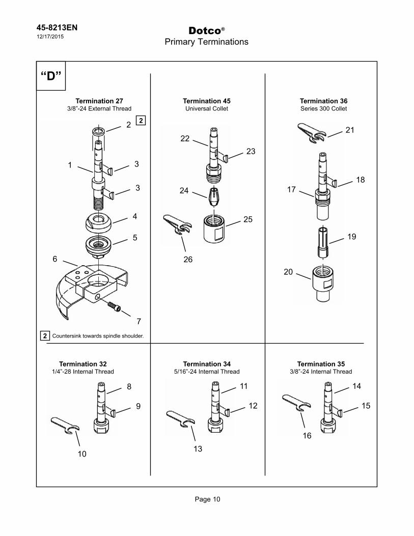
2 Countersink towards spindle shoulder.
2
Dotco®
Primary Terminations
Termination 273/8”-24 External Thread
Termination 321/4”-28 Internal Thread
Termination 345/16”-24 Internal Thread
Termination 353/8”-24 Internal Thread
Termination 36Series 300 Collet
Termination 45Universal Collet
2
3
3
4
5
1
6
7
22
24
23
25
26
9
8
10
12
11
13
15
14
16
18
21
19
17
20

Page 11
45-8213EN12/17/2015
Dotco®
Primary Terminations
ENDescription
1 1402PT 1 Spindle (includes Ref. 2)2 7792 1 1 Spacer3 1062PT 2 6 Woodruff Key4 14-1174 1 Flange5 14-1175 1 Flange6 14-1258 1 Wheel Guard (includes Ref. 7)7 14-1518 1 2 Cap Screw-- 14-0186 1 3/16" Wrench (not shown)-- 14-0809 1 9/16" Wrench (not shown)-- 14-0812 1 3/4" Wrench (not shown)
8 1069 1 Spindle9 1062PT 1 3 Woodruff Key
10 14-0807 1 7/16" Wrench
11 1284 1 Spindle12 1062PT 1 3 Woodruff Key13 14-0807 1 7/16" Wrench
14 1250PT 1 Spindle15 1062PT 1 3 Woodruff Key16 14-0807 1 7/16" Wrench
17 1029PT 1 Spindle18 1062PT 1 3 Woodruff Key19 Table "D1" 1 Collet (1/4")20 208196PT 1 Nosepiece
14-0807 1 7/16" Wrench14-0811 1 11/16" Wrench
22 7814S 1 Spindle23 1062PT 1 3 Woodruff Key24 Table "D2" 1 Collet (1/4")25 7815 1 Collet Nut
14-0807 1 7/16" Wrench14-0811 1 11/16" Wrench
(#) Quantity(X) Recommended Spare Parts (quantity shown based on 1-5 tools in operation)
Termination 45 - Universal Collet
26
Illustration "D"
Ref Number # X
21
Termination 36 - 300 Series, 1/4" (3 piece) Collet
Termination 27 - 3/8"-24 External Thread Spindle
Termination 32 - 1/4"-28 Internal Thread Spindle
Termination 34 - 5/16"-24 Internal Thread Spindle
Termination 35 - 3/8"-24 Internal Thread Spindle
Table "D1"
Part No. Arbor Size Part No. Arbor Size Part No. Arbor Size301PT 3/64" 305PT 5/32" 310PT 6mm302PT 5/64" 306PT 3/16"
303 3/32" 308PT * 1/4"304PT 1/8" 311 3mm
* Standard Collet
300 Series Optional ColletsTable "D2"
Part No. Arbor Size Part No. Arbor Size Part No. Arbor Size7809 1/8" 7811 6mm7812 3/16"
7808PT * 1/4"7810PT 3mm
* Standard Collet
Universal Series Optional Collets

Page 12
45-8213EN12/17/2015
Dotco®
Extended Terminations
“E” Termination -RT (Router)
2
3
18
7
“F” Termination -B1 (1/4” x 12” Belt Sander)
1
4
1
2 3
108
9
55
17
15
6
16
17
12
1413
1114
4

Page 13
45-8213EN12/17/2015
Dotco®
Extended Terminations
ENDescription
1 7197 1 Router Housing Assembly (includes Ref. 2-4)2 1098 1 2 Retaining Ring3 14-0508 1 2 Ball Bearing4 14-1518 1 1 Screw (#8-32 x .75 SHCS)
(#) Quantity(X) Recommended Spare Parts (quantity shown based on 1-5 tools in operation)
Illustration "E" - Router Termination (36RT)
Ref Number # X
ENDescription
-- 14-1638S 1 Belt Sander Assembly (includes Ref. 1-14)1 14-1297 1 Guard2 2826PT 1 1 Screw3 14-1619 1 Spacer4 14-1597 1 Boom5 1900PT 2 4 Screw6 1833PT 1 Pin7 14-1343 1 1 Cushioned Platen8 1904PT 1 2 Yoke Spring9 14-1617 1 Yoke
10 1831PT 1 1 Yoke Pin-- 14-1602 1 1 Wheel Assembly (includes Ref. 11-13)11 564PT 1 2 Ball Bearing12 14-1604 1 1 Wheel (includes Ref. 13)13 14-1616 1 3 Tire14 14-1618 2 Spacer15 14-1308 1 1 Drive Wheel (32B1 Termination) (includes Ref. 17)16 14-1309 1 1 Drive Wheel (36B1 Termination) (includes Ref. 17)17 14-1304 1 3 Tire18 14-1591 1 6 Sanding Belt (80 Grit)
14-1593 1 6 Sanding Belt (120 Grit)(#) Quantity(X) Recommended Spare Parts (quantity shown based on 1-5 tools in operation)
Illustration "F" - Belt Sander Termination B1
Ref Number # X

Page 14
45-8213EN12/17/2015
Dotco®
Extended Terminations
“G” Termination -B2 (1/2” x 12” Belt Sander)
20
9
“H” Termination -B3 (1/2” x 24” Belt Sander)
1
2
3
1210
11
54
17
19
7
18
19
15
13
16
14
136
587
20
9
1
2
3
1210
11
54
17
19
7
18
19
1516
14
136
587
13
Page 15
45-8213EN12/17/2015
Dotco®
Extended Terminations
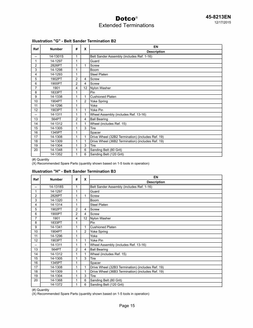
ENDescription
-- 14-1301S 1 Belt Sander Assembly (includes Ref. 1-16)1 14-1297 1 Guard2 2826PT 1 1 Screw3 14-1298 1 Boom4 14-1293 1 Steel Platen5 1902PT 2 4 Screw6 1900PT 2 4 Screw7 1901 4 12 Nylon Washer8 1833PT 1 Pin9 14-1338 1 1 Cushioned Platen
10 1904PT 1 2 Yoke Spring11 14-1296 1 Yoke12 1903PT 1 1 Yoke Pin-- 14-1311 1 1 Wheel Assembly (includes Ref. 13-16)13 564PT 2 4 Ball Bearing14 14-1312 1 1 Wheel (includes Ref. 15)15 14-1305 1 3 Tire16 1345PT 1 Spacer17 14-1308 1 1 Drive Wheel (32B2 Termination) (includes Ref. 19)18 14-1309 1 1 Drive Wheel (36B2 Termination) (includes Ref. 19)19 14-1304 1 3 Tire20 14-1348 1 6 Sanding Belt (80 Grit)
14-1352 1 6 Sanding Belt (120 Grit)(#) Quantity(X) Recommended Spare Parts (quantity shown based on 1-5 tools in operation)
Illustration "G" - Belt Sander Termination B2
Ref Number # X
ENDescription
-- 14-1318S 1 Belt Sander Assembly (includes Ref. 1-16)1 14-1297 1 Guard2 2826PT 1 1 Screw3 14-1320 1 Boom4 14-1314 1 Steel Platen5 1902PT 2 4 Screw6 1900PT 2 4 Screw7 1901 4 12 Nylon Washer8 1833PT 1 Pin9 14-1341 1 1 Cushioned Platen
10 1904PT 1 2 Yoke Spring11 14-1296 1 Yoke12 1903PT 1 1 Yoke Pin-- 14-1311 1 1 Wheel Assembly (includes Ref. 13-16)13 564PT 2 4 Ball Bearing14 14-1312 1 1 Wheel (includes Ref. 15)15 14-1305 1 3 Tire16 1345PT 1 Spacer17 14-1308 1 1 Drive Wheel (32B3 Termination) (includes Ref. 19)18 14-1309 1 1 Drive Wheel (36B3 Termination) (includes Ref. 19)19 14-1304 1 3 Tire20 14-1368 1 6 Sanding Belt (80 Grit)
14-1372 1 6 Sanding Belt (120 Grit)(#) Quantity(X) Recommended Spare Parts (quantity shown based on 1-5 tools in operation)
Illustration "H" - Belt Sander Termination B3
Ref Number # X

Page 16
45-8213EN12/17/2015
Dotco®
Extended Terminations
“J” Termination -B5 (1” x 24” Belt Sander)
1
17
18
23
21
19
3
20
21
16
7
15
14
2121
2
1714
18
12
12
13
9
9
114 10
10
6
58
1
17
18
23
21
19
3
20
21
16
7
15
14
2121
2
1714
18
12
12
13
9
9
114 10
10
6
58
“I” Termination -B4 (1” x 12” Belt Sander)

Page 17
45-8213EN12/17/2015
Dotco®
Extended Terminations
ENDescription
-- 14-1463 1 Belt Sander Assembly (32B4 Termination) (includes Ref. 1-22)-- 14-1473 1 Belt Sander Assembly (36B4 Termination) (includes Ref. 1-22)1 14-1356 1 Guard2 14-1471 1 Guard3 14-1498 1 1 Screw4 14-1464 1 Boom5 14-1466 1 Steel Platen6 1902PT 3 6 Screw7 7731 2 4 Screw8 1901 7 14 Nylon Washer9 14-1338 2 2 Cushioned Platen
10 14-1478 2 4 Yoke Spring11 14-1465 1 Yoke12 2193PT 2 4 Yoke Screw13 14-3036 1 1 Yoke Pin-- 14-1472 1 1 Wheel Assembly (includes Ref. 14-18)14 564PT 2 4 Ball Bearing15 14-1469 1 1 Wheel (includes Ref. 16)16 14-1305 2 6 Tire17 14-1467 2 Spacer18 1345PT 2 Spacer19 14-1468 1 1 Drive Wheel (32B4 Termination) (includes Ref. 21)20 14-1470 1 1 Drive Wheel (36B4 Termination) (includes Ref. 21)21 14-1304 2 6 Tire22 14-0184PT 1 Wrench (1/8") (not shown)23 14-1583 1 6 Sanding Belt (80 Grit)
14-1585 1 6 Sanding Belt (120 Grit)(#) Quantity(X) Recommended Spare Parts (quantity shown based on 1-5 tools in operation)
Illustration "I" - Belt Sander Termination B4
Ref Number # X
ENDescription
-- 14-1603 1 Belt Sander Assembly (32B5 Termination) (includes Ref. 1-22)-- 14-1613 1 Belt Sander Assembly (36B5 Termination) (includes Ref. 1-22)1 14-1356 1 Guard2 14-1471 1 Guard3 14-1498 1 1 Screw4 14-1614 1 Boom5 14-1615 1 Steel Platen6 1902PT 3 6 Screw7 7731 2 4 Screw8 1901 7 14 Nylon Washer9 14-1341 2 2 Cushioned Platen
10 14-1478 2 4 Yoke Spring11 14-1465 1 Yoke12 2193PT 2 4 Yoke Screw13 14-3036 1 1 Yoke Pin-- 14-1472 1 1 Wheel Assembly (includes Ref. 14-18)14 564PT 2 4 Ball Bearing15 14-1469 1 1 Wheel (includes Ref. 16)16 14-1305 2 6 Tire17 14-1467 2 Spacer18 1345PT 2 Spacer19 14-1468 1 1 Drive Wheel (32B5 Termination) (includes Ref. 21)20 14-1470 1 1 Drive Wheel (36B5 Termination) (includes Ref. 21)21 14-1304 2 6 Tire22 14-0184PT 1 Wrench (1/8") (not shown)23 14-1643 1 6 Sanding Belt (80 Grit)
14-1645 1 6 Sanding Belt (120 Grit)(#) Quantity(X) Recommended Spare Parts (quantity shown based on 1-5 tools in operation)
Illustration "J" - Belt Sander Termination B5
Ref Number # X