pk 120 manual usuario
TRANSCRIPT
1
1. MANUFACTURER
For more information about the ALC PK120centrifuge, please contact:ALC170 Marcel DriveWinchester, VA 22602Telephone (540) 869-8623Toll Free (800) 556-2323Fax (540) 869-0693
1.1 Safety Devices and Notices
To ensure operator safety the centrifuge hasthe following electrical and mechanicalcharacteristics :
• The centrifuge will not start unless the lid islocked.
• The lid cannot be opened duringcentrifugation.
• The centrifuge has electronic self-diagnosiscapability; any possible electrical systemmalfunctions are displayed digitally. At thesame time, the centrifuge is disabled toprevent unsafe operation of the machine.
• The centrifuge is equipped with anautomatic load imbalance safety device.
• The case of the centrifuge is armored, andthe reinforced bowl is made of AISI 304stainless steel.
• The lid is supported by a strong, dependablegas spring that holds the lid open until theoperator actively closes it.
• The electrical main has a bipolar switch.
• Ground connection resistance, appliedvoltage and leakage current are tested andcertified.
• The centrifuge is equipped with identificationplates and operating instructions.
2. INSTALLATION
2.1 Transport, Packaging, Lifting
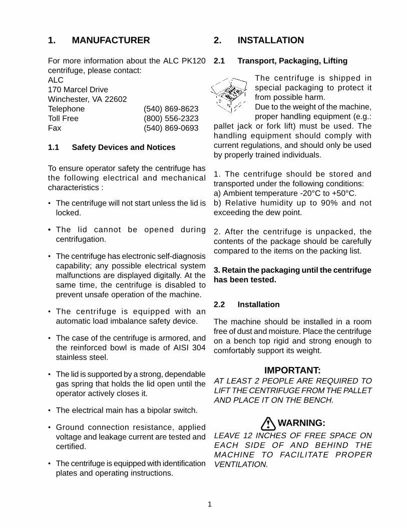
The centrifuge is shipped inspecial packaging to protect itfrom possible harm.Due to the weight of the machine,proper handling equipment (e.g.:
pallet jack or fork lift) must be used. Thehandling equipment should comply withcurrent regulations, and should only be usedby properly trained individuals.
1. The centrifuge should be stored andtransported under the following conditions:a) Ambient temperature -20°C to +50°C.b) Relative humidity up to 90% and notexceeding the dew point.
2. After the centrifuge is unpacked, thecontents of the package should be carefullycompared to the items on the packing list.
3. Retain the packaging until the centrifugehas been tested.
2.2 Installation
The machine should be installed in a roomfree of dust and moisture. Place the centrifugeon a bench top rigid and strong enough tocomfortably support its weight.
IMPORTANT:AT LEAST 2 PEOPLE ARE REQUIRED TOLIFT THE CENTRIFUGE FROM THE PALLETAND PLACE IT ON THE BENCH.
WARNING:LEAVE 12 INCHES OF FREE SPACE ONEACH SIDE OF AND BEHIND THEMACHINE TO FACILITATE PROPERVENTILATION.
2
2.3 Power Source Wiring
Check main lines and frequency:They must correspond to thevalues shown on the instrumentidentification label.
PK120 230V:230 V + 5% - 10% 50 Hz (1 phase + ground)
PK120 120V:120 V + 5% - 10% 60 Hz (1 phase + ground)
WARNING:ENSURE THAT THE POWER SOURCE ISPROPERLY GROUNDED.
The centrifuge is equipped with R.F.I. filters.The manufacturer declines all responsibilityfor any damages due to improper groundingof the machine.
2.4 Environmental conditions
- Indoor use.- Temperature: 5°C to + 40°C.- Maximum relative humidity: 80% for
temperatures up to 31°C decreasing linearlyto 50% relative humidity at 40°C.
2.5 Lid Unlock
1. Turn the centrifuge on (switch is onthe left side of the unit).
2. Check the lid indicator on the display panel.The light should be on indicating that the rotoris stationary and that the lid can be opened.
3. Pull the lever on the top right side of themachine to open the lid.
WARNING:BEFORE PROCEEDING TO THEINSTALLATION OPERATION, IT ISIMPORTANT TO TURN THE CENTRIFUGEOFF.
4. After opening the lid, remove any possiblepackaging around the spindle. Unscrew therotor nut from the top of the spindle. Carefullyclean the inside of the centrifugation chamberremoving any packaging residue. Because ofthe turbulence caused by centrifugation, solidparticles accidentally left in the chamber couldcreate excessive wear of the bowl and rotor.
2.6 Emergency Lid Unlock
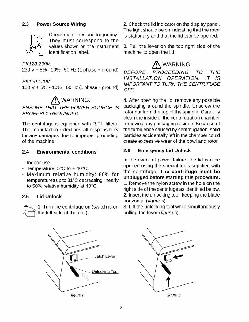
In the event of power failure, the lid can beopened using the special tools supplied withthe centrifuge. The centrifuge must beunplugged before starting this procedure.1. Remove the nylon screw in the hole on theright side of the centrifuge as identified below.2. Insert the unlocking tool, keeping the bladehorizontal (figure a).3. Lift the unlocking tool while simultaneouslypulling the lever (figure b).
figure a figure b
Latch Lever
Unlocking Tool

3
4. After the lid is open, replace the nylon screw.
WARNING:SHOULD THE POWER FAIL DURINGCENTRIFUGATION, WAIT AT LEAST 40MINUTES FOR THE ROTOR TO STOPTURNING. OPEN THE LID CAUTIOUSLYAND OBSERVE THE ROTOR; IF IT IS STILLROTATING, CLOSE THE LID AND WAIT 10MINUTES MORE BEFORE REPEATING THEOPERATION.
2.7 Inspection
Before installation, the rotating equipmentshould be thoroughly inspected for corrosionand dirt (see 6.3). The rotor and spindle shouldbe clean and undamaged. These accessoriesshould be wiped clean before each use. Anyfailure to follow the above advice may haveserious consequences for the safety of theappliance. Corrosion can lead to stressfatigue, which will eventually weaken the rotorand may lead to disruption and severedamage to the centrifuge. If visible signs ofcorrosion or anomalies in the rotor or bucketsare present, do not use the affectedaccessories. Contact an authorized serviceprovider for assistance.
2.8 Fitting the Rotor to the Drive Shaft
- Remove the rotor fixing shaft nut.- Check the cleanliness of the shaft and
the rotor.- Place the rotor on the shaft .- Secure the rotor on the shaft by turning
the fixing nut clockwise.- Tug on the rotor to make sure that it is
secure.
WARNING:BE SURE THAT THE ROTOR IS LOCKEDBEFORE STARTING THE CENTRIFUGE.
2.9 Removal of the Rotor
To remove the rotor from the motor shaft :Using the wrench supplied, unlock the shaftnut. Remove the nut and lift the rotor with bothhands.

4
3. SPECIFICATIONS3.1 Dimensions and weight
Height x Width x Depth: ......................... 14.8 x 15.7 x 18.9 in (37.5 x 40 x 48 cm)Net Weight: ............................................ 88 lbs. (40 kg)
3.2 Centrifugation characteristics
Max. allowable capacity: ........................ with swing-out rotor 4 x 190 mlwith fixed-angle rotor 6 x 50 ml
Max. Allowable density: ......................... 1200 Kg/ m3
Max. allowable weight:........................... 0.912 KgMax. speed: ........................................... with swing-out rotor 4000 rpm with fixed-angle rotor 6000 rpm
Max. RCF at tip: ..................................... with swing-out rotor 2879 x gwith fixed-angle rotor 4507 x g
Set temperature: .................................... Ta + ∆T
Max. noise: ............................................ < 62 dBA
3.3 Electrical characteristics
Nominal operating voltage: .................... 230V + 5% - 10% 50 Hz120V + 5% - 10% 60 Hz
Current................................................... 3.8A (@ 230V)7.6A (@ 120V)
Max power (steady state): ..................... 350 W
3.4. Specifications
• Microprocessor controlled• 5 program memory, direct recall• Set/reading speed 300 - 6000 rpm (in steps of 10 rpm or 100 rpm); accuracy: +/- 20 rpm• 5 acceleration profiles• 5 deceleration profiles• Set timer 1 min. up to 99 min. + ∞• Electronic imbalance detector• Direct drive• Brushless induction motor
5
4. DESCRIPTION OF PERFORMANCE
4.1 Functional principles
The ALC PK120 centrifuge is designed forlaboratory use. It will separate the componentsof fluids into layers of varying density bysubjecting them to high forces. Swing outrotors can carry a greater load than fixed anglerotors. The larger the diameter of a rotor, withaccessories, the greater its load capacity andthe lower its maximum speed. RelativeCentrifugal Force (RCF) generated by a rotoris directly proportional to its sedimentationuseful radius and to the value of its speedsquared.
4.1.1 Drive system
A three phase asynchronous motor drives therotating equipment. The rotor is contained ina sealed, armor plated centrifugation chamber.
4.1.2 Lid interlock safety system
The centrifuge is equipped with an interlocksystem that prevents opening of the centrifugelid when the rotor is spinning. The centrifugewill not operate until the lid is closed andlatched in place. The lid remains latched untilthe rotor stops spinning. NOTE: If a powerfailure occurs, access to the samples in thecentrifuge is possible. For this it is necessaryto use a special tool. Follow the emergencylid unlock procedure found in Section 2.6.
4.1.3 Imbalance Sensor
The centrifuge is equipped with a loadimbalance detector. In case of excessiveimbalance the machine stops automatically.The display reads “IMbAL” – this message willdisappear once the lid has been opened tobalance the load (see Section 5.10).Imbalance tolerance depends upon the rotorin use. Carefully balance the sample load toavoid actuating the imbalance detectionsystem.
6
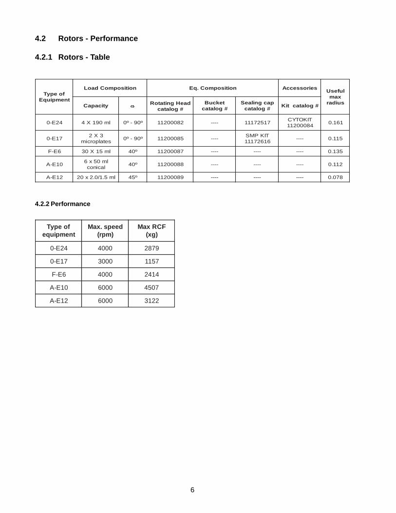
4.2 Rotors - Performance
4.2.1 Rotors - Table
4.2.2 Performance
foepyTtnempiuqE
noitisopmoCdaoL noitisopmoC.qE seirosseccA lufesUxamsuidaryticapaC aaaaa daeHgnitatoR
#golatactekcuB#golatac
pacgnilaeS#golatac
#golatactiK
42E-0 lm091X4 º09-º0 28000211 ---- 71527111TIKOTYC48000211
161.0
71E-03X2
setalporcimº09-º0 58000211 ----
TIKPMS61627111
---- 511.0
6E-F lm51X03 º04 78000211 ---- ---- ---- 531.0
01E-Alm05x6
lacinocº04 88000211 ---- ---- ---- 211.0
21E-A lm5.1/0.2x02 º54 98000211 ---- ---- ---- 870.0
foepyTtnempiuqe
deeps.xaM)mpr(
FCRxaM)gx(
42E-0 0004 9782
71E-0 0003 7511
6E-F 0004 4142
01E-A 0006 7054
21E-A 0006 2213

7
4.3 RCF Calculation
Total separating force applied to a sample ina centrifuge depends on the duration of thecentrifuge run and on the RCF (relativecentrifuge force) applied to the sample. RCFis generally calculated in units x gravity (x g).The diagram above allows you to graphicallycalculate RCF by drawing a line from thecentrifugal radius (on left) to the speed (onright). The value of the RCF (xg) applied tothe sample is approximated by the value atthe point where the line crosses the “xg” axis(center).
Centrifugal radius is defined as the distancefrom the axis of rotation to the point on thesample at which you wish to measure the RCF.This point is generally the tip of the sample
radius RPM xg
farthest from the axis of rotation. By popularconvention, this distance is measured in unitsof millimeters.
EXAMPLE
To find the RCF value (xg) applied to a samplein a rotor/bucket/accessory system with acentrifugal radius of 100 mm (0.1m) androtating at 3000 RPM, place a ruler on thescale joining the point marked 100 on the leftwith the point marked 3000 on the right. Atthe point where the line crosses the centerscale (xg), the corresponding value isapproximately 1,000. In this example, theouter tip of the sample is subjected to RCF =1,000 x g
8
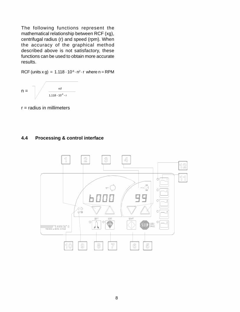
The following functions represent themathematical relationship between RCF (xg),centrifugal radius (r) and speed (rpm). Whenthe accuracy of the graphical methoddescribed above is not satisfactory, thesefunctions can be used to obtain more accurateresults.
RCF (units x g) = 1.118 · 10-6 · n2 · r where n = RPM
n =
r = radius in millimeters
1,118 * 10-6 * r
rcf
4.4 Processing & control interface

9
1. Speed display (units of rpm) When themachine is stopped, this field displays theset speed. When the machine is runningand the numbers are constant, this fielddisplays actual speed. When the machineis running and the numbers are flashing,this field displays set speed.
2. SET rpm keys : These keys areused for increasing or decreasing speedsettings.
3. Time display (units of minutes) Whenthe machine is stopped, this field displaysthe set centrifugation time. When themachine is running, the remainingcentrifugation time is displayed; when thetime is set at “HOLD” (continuousoperation), the display shows elapsedtime.
4. Set minutes keys : These keysare used for increasing or decreasing timesettings.
5. STOP key Pressing this key stops thecentrifuge manually. When pressedsimultaneously with key No. 12, it togglesthe password protection of the programsin memory.
6. START key Pressing this key starts thecentrifugation cycle.
7. SOFT deceleration key This key is usedto set low braking rate (illuminated LEDindicates “on”). The braking rate can alsobe more precisely programmed to one of5 deceleration profiles.
8. SOFT acceleration key This key is usedto set low acceleration rate (illuminatedLED indicates “on”). The acceleration ratecan also be more precisely programmedto one of 5 acceleration profiles.
9. GREEN LED: This indicator flashes duringthe acceleration and the decelerationphases. It is constant when actual speedequals set speed.
10.YELLOW LED : When this indicator isilluminated the lid can be opened. It comeson when the rotor is stationary.
11. Five PROGRAM KEYS : for quickprogramming and recall of 5 profiles.
13.Five LED indicators next to programkeys : When a program is selected, itscorresponding LED is illuminated.
10
5. OPERATION PROCEDURE
5.0 Instructions for the operator
1. As a precautionary measure, the operatorshould remain with the centrifuge until itreaches the set speed.
2. The operator should also return to thecentrifuge immediately upon completion ofthe run.
5.1 Power Switch - Cover Unlock
1. When the centrifuge is turned on (switchis located on the left side of the centrifuge)both the centrifuge and the refrigerationcircuit are connected to the main circuit.
2. When the rotor is stationary and the LEDis on, it is possible to unlock the lid. Themechanical latch on the upper right panelof the centrifuge opens the lid when it ispulled toward the front.
5.2 Loading balance
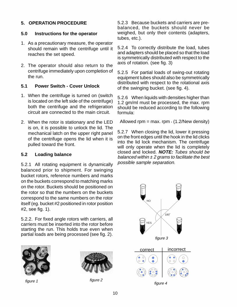
5.2.1 All rotating equipment is dynamicallybalanced prior to shipment. For swingingbucket rotors, reference numbers and markson the buckets correspond to matching markson the rotor. Buckets should be positioned onthe rotor so that the numbers on the bucketscorrespond to the same numbers on the rotoritself (eg. bucket #2 positioned in rotor position#2, see fig. 1).
5.2.2. For fixed angle rotors with carriers, allcarriers must be inserted into the rotor beforestarting the run. This holds true even whenpartial loads are being processed (see fig. 2).
correct incorrect
figure 4
11
22
figure 1 figure 2
5.2.3 Because buckets and carriers are pre-balanced, the buckets should never beweighed, but only their contents (adapters,tubes, etc.).
5.2.4 To correctly distribute the load, tubesand adapters should be placed so that the loadis symmetrically distributed with respect to theaxis of rotation. (see fig. 3)
5.2.5 For partial loads of swing-out rotatingequipment tubes should also be symmetricallydistributed with respect to the rotational axisof the swinging bucket. (see fig. 4).
5.2.6 When liquids with densities higher than1.2 gm/ml must be processed, the max. rpmshould be reduced according to the followingformula:
Allowed rpm = max. rpm * (1.2/New density)
5.2.7 When closing the lid, lower it pressingon the front edges until the hook in the lid clicksinto the lid lock mechanism. The centrifugewill only operate when the lid is completelyclosed and locked. NOTE: Tubes should bebalanced within ± 2 grams to facilitate the bestpossible sample separation.
figure 3
YES
NO
180˚
11
5.3 Centrifuge Operation
INTRODUCTION: The control interface of thePK120 is designed to make centrifugeoperation as simple as possible. All of thebuttons are dedicated to specific functions.Because of this, centrifuge operators do notneed extensive training to understand thesystem. This section is designed to educateand prepare the user to use the PK120. Thefollowing centrifugation parameters can be setby the operator:
a) Speed in rpm (300 rpm up to 6,000 rpm).b) Centrifugation time (1 min up to 99 min + ∞)c) Temperature (-10°C to +40°C)d) Acceleration (5 profiles)e) Braking (5 profiles)
The microprocessor allows the centrifuge tobe operated in MANUAL or in PROGRAMoperative mode.
5.3.1 MANUAL Operative Mode
Manual operative mode is active when noneof the five programs is activated. When thecentrifuge is in manual mode, none of theLED’s next to the program keys areilluminated. In manual mode, all of theparameters can be changed regardless if thecentrifuge is running or on stand-by. Forexample: The user approaches the centrifugewishing to operate it in manual mode. The LEDindicator next to Program #3 is illuminated.To put the centrifuge into Manual mode, theuser presses the button corresponding toProgram #3 once. The LED goes off, indicatingthat the centrifuge is now in Manual mode.
5.3.2 PROGRAM Operative ModeUp to 5 programs can be stored in the memoryof the PK120. To set or change programs,follow this procedure:• Make sure that the centrifuge is in
MANUAL mode (all LED indicators nextto program buttons are off).
• Set all parameters for your desiredprogram. The display numbers will blinkfor about three seconds after you are doneprogramming.
• Before the numbers stop blinking, pressthe program button for the programnumber under which you wish to store theprotocol. This will save the newly-createdprogram.
• To select a program, press the buttoncorresponding to the program number thatyou wish to recall.
5.4 Setting Centrifugation Parameters
5.4.1 Default Condition
The centrifuge is always in the same operativemode as at the time of its last use. When thecentrifuge is idle the display reads:
°C- Real temperature in the centrifugationchamber
rpm - set speedmin - set time
12
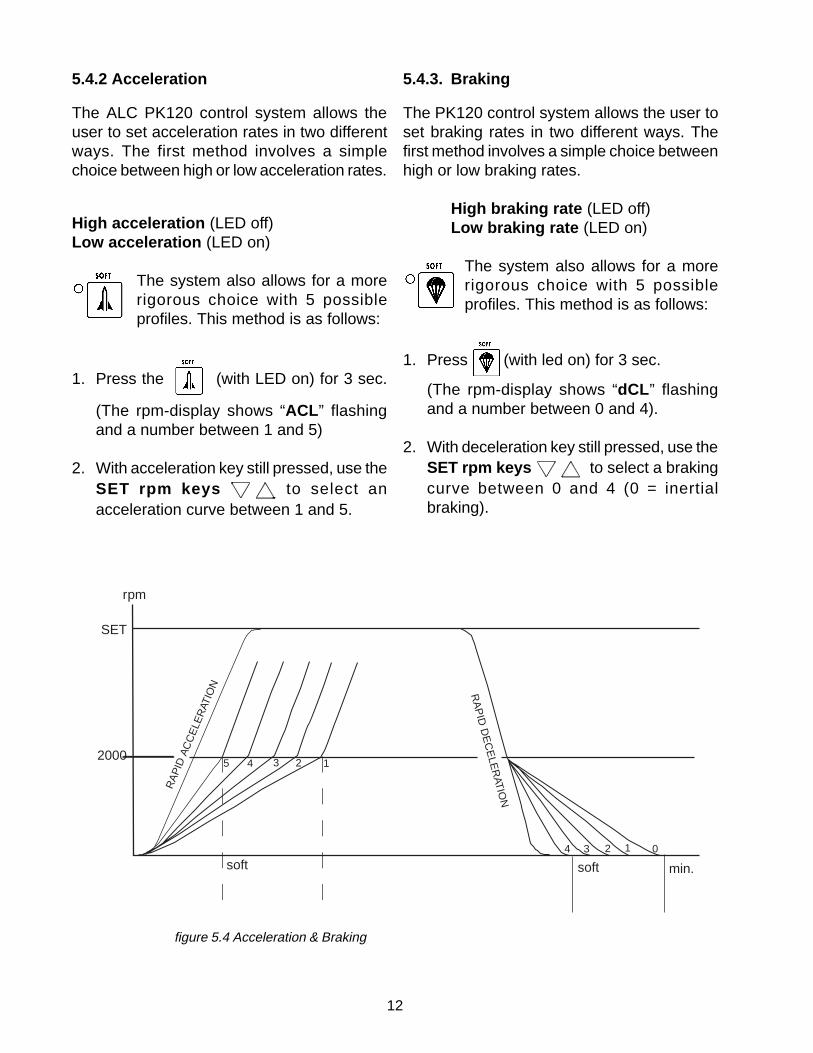
5.4.2 Acceleration
The ALC PK120 control system allows theuser to set acceleration rates in two differentways. The first method involves a simplechoice between high or low acceleration rates.
High acceleration (LED off)Low acceleration (LED on)
The system also allows for a morerigorous choice with 5 possibleprofiles. This method is as follows:
1. Press the (with LED on) for 3 sec.
(The rpm-display shows “ACL ” flashingand a number between 1 and 5)
2. With acceleration key still pressed, use theSET rpm keys to select anacceleration curve between 1 and 5.
5.4.3. Braking
The PK120 control system allows the user toset braking rates in two different ways. Thefirst method involves a simple choice betweenhigh or low braking rates.
High braking rate (LED off)Low braking rate (LED on)
The system also allows for a morerigorous choice with 5 possibleprofiles. This method is as follows:
1. Press (with led on) for 3 sec.
(The rpm-display shows “dCL ” flashingand a number between 0 and 4).
2. With deceleration key still pressed, use theSET rpm keys to select a brakingcurve between 0 and 4 (0 = inertialbraking).
5 4 3 2 1
rpm
SET
2000
soft soft min.
01234
RA
PID
AC
CE
LER
ATIO
N RA
PID
DE
CE
LER
ATIO
N
figure 5.4 Acceleration & Braking

13
5.4.4. Setting speed and time values
- When you touch one of the SET keys , the corresponding display will start
to flash.- When the display flashes, it is possible to
change the selected parameter using theSET keys .
SET speed 300 to 6000rpm (see 4.2 for rotorspeed ratings).
SET time 1 to 99 min + hold
3 seconds after changes are complete, thedisplay stops flashing. This confirms the newSET values.
5.5 Storing a program in memory
BASIC CONDITION: Centrifuge stationaryand “MANUAL” Operative Mode.
1. To store the SET parameterspress one of the program keysbetween 1 and 5 while the displayis still flashing (within threeseconds of the last buttonoperation) . The LED next to theprogram key will light up, confirmingthat the program has beenmemorized. NOTE: It is not possibleto set a program with time set to“HOLD”: if you try to put a “HOLD”program into memory, the timerdisplay will continue flashing; youmust enter a determinate time value.
2. To restore “MANUAL MODE ”, press theselected program key ; the LEDcorresponding to the program key goes offand it is possible to create a new program.
5.6 Protecting a program
1. To protect a program, press theLOCK PROG key (STOP)simultaneously with the programkey when saving the program.
2. To cancel the program protection, pressthe LOCK PROG key (STOP)simultaneously with the program key.
5.7 Starting the centrifuge
BASIC CONDITION: Lid closed
1.Press “START” key.
In MANUAL OPERATIVE MODEand in PROGRAM MODE, thecentrifuge will accelerate to the setspeed. When the run time iselapsed, the centrifuge will brake toa stop.
- During the run time the speed displayshows actual values. The time displayshows remaining run time. If the timesetting is “HOLD”, the time display showselapsed run time.
- The green LED on the left side of thecontrol panel flashes while the rotor isaccelerating and remains constantlyilluminated while the rotor is at set speed.
NOTE: if set speed is higher than themaximum speed of the rotor, the green LEDwill continue flashing (see 5.10 SET). In thiscase, the program should be corrected assoon as possible.
14
2. During the run in “MANUAL” MODE Toread and change set values, press theSET cursors:
- The display starts to flash and shows theset values for 3 seconds.
- While the display is flashing it is possibleto change the set values.
- During a run in MANUAL mode it ispossible to change the deceleration
3. During the run in “PROGRAM” MODE,it is possible to display set values bypressing the corresponding SET cursors.It is not possible to change theprogrammed values.
5.8 Stopping the centrifuge
Once the pre-set time has elapsed,the centrifuge automatically stopsthe rotor at a rate determined by thedeceleration setting.
Pressing at any time will cause the
centrifuge to stop the rotor. NOTE: Automaticbraking will occur under conditions of loadimbalance, power failure, error or breakdown.In all cases the relevant code will appear onthe message display.
5.9 Messages - Alarms
The microprocessor displays error messagesto indicate errors, malfunctions or breakdowns.The messages are expressed with thefollowing codes.
End Appears at the end of everycentrifugation cycle after the rotor comesto a stop. The message disappears whenthe lid is opened or when any key ispressed.
Lid Appears when the (start button) ispressed and the lid is not locked. The “LID”message is accompanied by an audiblesignal. This message will disappear whenthe lid is locked.
IMbAL Appears when the load is unbalanced.The message is accompanied by anaudible signal. The centrifuge stops toallow the user to rebalance the load (5.2).The message disappears when the lid isopened.
MAInS Appears when a power failure occurs.The centrifuge decelerates and the systemshuts down. When power is restored, themessage reappears. It remains on thedisplay until the next operation is started.
SET Appears when set speed is higher thanthe maximum rated speed of the rotor. Themessage disappears when the centrifugeis stopped or when the parameter iscorrected in Manual Operative Mode.
E01-E09 Messages ‘E0..’ (e.g. E01) togetherwith an acoustic alarm indicate failureconditions. The ‘E04’ message will appearon the display after a power failure, in thiscase wait for the rotor head to stop beforeopening the lid. In the other cases contactALC Customer Service.

15
6. HAZARDS, PRECAUTIONS AND USELIMITATIONS
6.1Dangerous operations - workconditions to avoid
• Using the centrifuge if it has not beenproperly installed.
• Fitting the rotor on the drive shaftincorrectly or placing the buckets on therotor incorrectly.
• Leaning on the machine.
• Placing dangerous objects in the area ofthe centrifuge.
• Moving or shifting the machine duringcentrifugation.
• Using the centrifuge with rotors and/orbuckets showing corrosion, wear marksand/or cracking.
• Using the centrifuge with rotors and/oraccessories not approved by themanufacturer.
• Using the centrifuge in explosiveenvironments or with explosive samples orchemical materials subject to violentreaction.
• Running an Unbalanced load whichcauses excessive vibration of thecentrifuge.
• Running a rotor without its full complementof buckets or carriers, even for partialloads.
• Leaving the appliance exposed to theelements (rain, sun, etc.).
• Exceeding the maximum speed indicated
in the “max. rpm” column of theperformance table (see 4.2.2).
• Using old accessories on a new machine.
• Using tubes and/or bottles not suited forcentrifugation.
• Spinning samples of densities higher thanallowed for the given speed.
• Alteration of and/or tampering with theelectronic and mechanical parts of thecentrifuge.
6.2 EN 61010-2-020 STANDARD
The En 61010-2-020 standard relative tolaboratory centrifuges recommends that theuser:
- Mark out a clearance envelope 300 mmaround the centrifuge or establish specialprocedures for the non entry of all personsor all dangerous materials into this spaceduring the operation of the centrifuge.
- Provide an emergency stop switchenabling the main power source to be cutin the case of malfunction. The switchshould be placed at a safe distance fromthe centrifuge, preferably in a differentroom from that in which the centrifuge issituated.
16
6.3 Rotor and accessory precautions6.3.1 Corrosion information
ALC rotors are made of aluminium alloy andare designed to operate at their rated RCFfor many years. With careful use they willresist corrosion, lowering the possibility ofexcessive imbalance, disruption andsubsequent damage to the instrument. Theprimary conditions for the initiation ofcorrosion exist in every laboratory during dailyuse of the centrifuge. For this reason it isessential that due care and attention be paidto inspection and cleaning.
CHEMICAL CORROSIONThis corrosion is characterized by chemicalreactions due to the existence of anyelectrolytic liquid on the surface of theequipment. If these substances are allowedto remain on the surface corrosion will almostcertainly occur. The first sign of this type ofcorrosion is a discoloration or pitting of theanodized surface.
Acidic and alkaline solutions sustaining theirpH level will also create corrosion ofaluminium equipment. Chlorides, which arepresent in salts (human skin secretions are acommon source!), are among the mostaggressive and harmful substancescommonly found in the laboratory.
Chemical products that cause corrosion donot necessarily originate from broken tubes.For example, they could come from:•· Chemical vapors present in the laboratory
which condense on the centrifuge and itsaccessories.
• Corrosive liquids originating from overfilleduncapped tubes (the liquid overflowsduring centrifugation)
• Inserts, adapters, racks and bottles withexteriors soiled by a chemical product orpoorly rinsed after decontamination (withbleach, for example).
NOTE: If the products are very corrosive,simple rinsing is insufficient. Residual traces
dissolve little by little with the humidity presentin the bottom of the rotor pocket.BEWARE of the presence of solid particlesbeneath tubes, inserts, racks or adapters.These particles are crushed by the centrifugalforce and penetrate the protective, anodizedlayer of buckets and rotors, thus creatingpathways for corrosion.
STRESS CORROSIONThis term relates to the phenomenon ofaccelerated corrosion due to the effect ofcentrifugal force when a corrosive chemical isin contact with the alloy. From the time whenthe aluminium alloy has been attacked bychemicals, stress corrosion begins to appear.As it occurs on a microscopic scale it is evenmore dangerous than macroscopic corrosionsince it is invisible to the naked eye.
During centrifugation chemicals responsible forcorrosion are also subjected to very highforces, which push them against the alloy. Thisclose contact facilitates the chemical reactionwhich occurs much faster than it does in astatic situation. Moreover, centrifugal force isdirectional. Because of this, corrosion understress creates, with a very small amount ofcorrosive product, straight microscopicfissures. Each centrifugation run allows thechemical to migrate further and further.
Fissures or cracks, although microscopic, area flaw in the metal, breaking the cohesion ofthe material. As one weak link in a chain allowsthe chain to break, so the microfissures breakthe chain of resistance of the accessory tocentrifugal force. Because accessories aredesigned with high safety factors, rupture doesnot occur as soon as the first microfissuresare produced.
Depending on the location of the fissure,disruption may occur before it reaches theexternal surface of the accessory. The fissurecreates a weakness, which makes theaccessory less and less resistant tomechanical fatigue. The corrosion caused by
17
a small amount of corrosive product does notdisrupt the accessory but makes itmechanically weaker and weaker untildisruption occurs due to both centrifugal forceand fatigue.
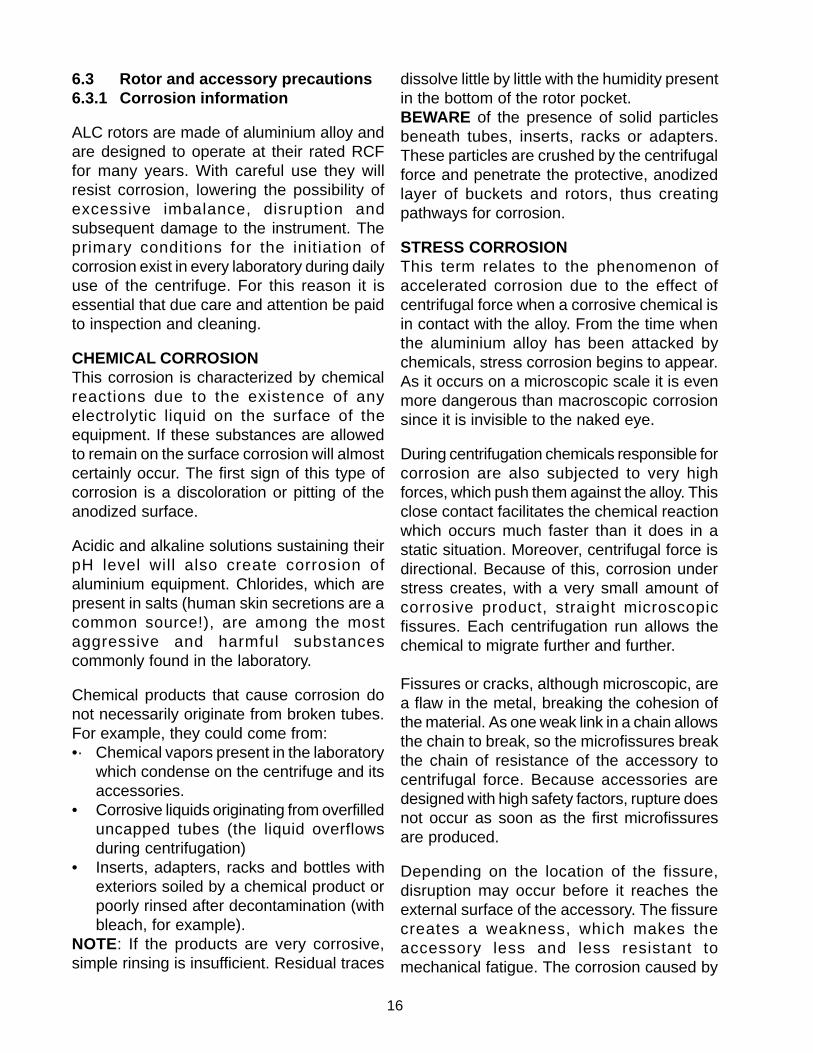
WARNING:BECAUSE STRESS CORROSION ISLARGELY INVISIBLE, IT IS ESSENTIAL THATROTATING EQUIPMENT BE SCRUTINISEDREGULARLY PAYING PARTICULARATTENTION TO SUSCEPTIBLE PARTS SUCHAS THE BOTTOM OF POCKETS, THE OUTEREDGES AND THE BASE OF THE ROTATINGEQUIPMENT.
6.3.2 Contamination hazards
ALC centrifuges are likely to be used inlaboratories where hazardous substances arefrequently present.
WARNING:THE USER HAS THE RESPONSIBILITYFOR CARRYING OUT APPROPRIATEDECONTAMINATION PROCEDURES.USERS SHOULD BE AWARE OF THEINTERNATIONALLY RECOGNIZED“LABORATORY BIOSAFETY MANUAL”,WHICH GIVES INFORMATION ONDECONTAMINATES, THEIR USE,DILUTIONS, PROPERTIES ANDPOTENTIAL APPLICATIONS. IFHAZARDOUS MATERIAL IS SPILLED ONOR INSIDE THE APPLIANCE, CLEANTHE APPLIANCE AND ITS DRAIN HOSEUSING APPROPRIATE METHODS.
If decontamination procedures require the useof warming (eg. autoclave) the rotatingequipment should always be completelydisassembled before being subjected to heat.They should also be completely disassembledprior to external chemical cleaning. Seals,tubes and plastic components should bedecontaminated with the method most suitablefor them, which might not be the same as forthe rotating equipment.
Note that the black color on the surface of therotating equipment will be gradually washedout if the rotor is regularly autoclaved orbleached. This does not necessarily denotedegradation of the anodized surface.
WARNING: ANY PART WHICH HAS BEEN SUBJECTEDTO TEMPERATURES ABOVE 130°C MUSTBE DISCARDED.
WARNING:IF YOU HAVE A DOUBT ABOUT APARTICULAR CLEANING METHOD,PLEASE CONTACT ALC TO VERIFY THATTHE PROPOSED METHOD DOES NOTDAMAGE THE APPLIANCE.
ALC makes no claims as to the effectivenessof proprietary brands of decontaminatingsolutions.
STRESS CORROSION CHEMICAL CORROSION

18
7. ROUTINE MAINTENANCE
CAUTION:During maintenanceoperations, ALWAYSdisconnect the centrifugefrom the main powersource (fig. 7.1).
7.1 Rotating Equipment andCentrifugation Chamber Cleaning
Regular cleaning of rotors and of thecentrifugation chamber is vital to maintaingood working conditions. The operator mustwear proper protective equipment during thecleaning (mask, gloves, etc.). It is alsoimportant to verify the integrity of biosafetycomponents when they are used. The usershould always inspect the condition of sealsand lids prior to using them. Do not cleanthem with materials that damage silicone andpolycarbonate. Ideally, rotors should bewashed after every run (at least weekly) inwarm water containing a few drops of mild (notalkaline) detergent (domestic liquid soap isideal). ROTORS MUST BE WASHED EVERYTIME SPILLAGE OCCURS . Do not forget towash the core of the rotating head that comesinto contact with the drive spindle. Each rotorpocket (and bucket for swing-out rotors) mustbe washed thoroughly using a small nylonbrush. Once the rotor has been removed, it iseasy to clean the centrifugation chamber andgaskets. Use warm water with non- alkalinedetergent. Do not use corrosive solvents.Once the rotor is clean, rinse it with runningwater, preferably distilled. Dry the rotor with asoft absorbent non-woven cloth or tissue. Theequipment can be dried with a cloth or with ahair dryer. DO NOT USE METAL WIREBRUSHES and MAKE CERTAIN THATROTOR SLOTS AND BUCKETS ARE WELL-DRIED (fig. 7.2). NEVER LEAVE damp rotorson a metal surface (particularly stainless steel)because an electrochemical reaction could
take place with the aluminium or magnesiumin the rotor. For swing-out rotors, be sure toclean the dirty grease from the studs andreplace it with a small amount of fresh grease.This will ensure that the buckets swing freely.The majority of imbalance problems arise fromthe failure of the user to clean and grease thestuds. Never apply grease if studs andbalancing slots have not been carefullycleaned (fig. 7.3 a/b). Use only the samekind of greases furnished in the rotorpackaging.
fig. 7.1
fig. 7.2
fig. 7.3
\
19
7.2 Exterior cleaning
For correct cleaning, a light domestic-usedetergent is recommended. A mixture of 50%isopropyl alcohol and water is also suggestedbecause it will not damage the labels.
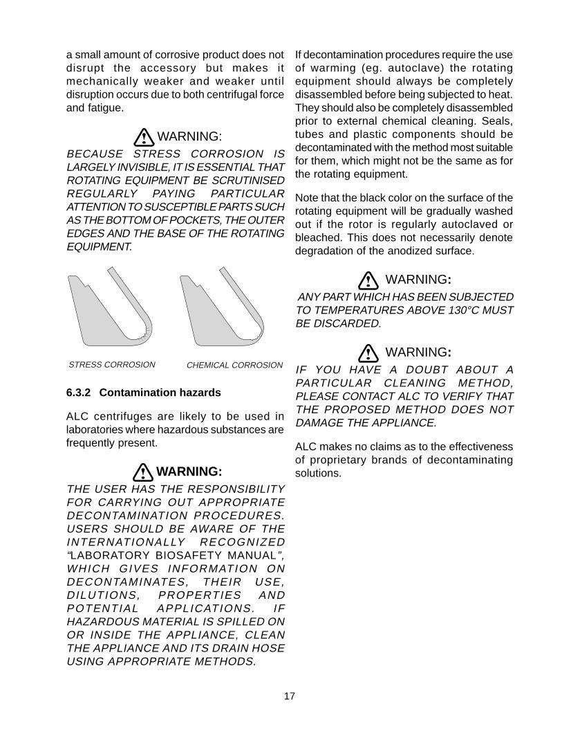
7.3 Fuses
There are two fuses in the power supply line.They are located in the power receptacleunder the line cord. (see fig. 7.4)
Fuse Specifications:
230V(50-60HZ) 5 x 20 mm TA4/250V
120V (60HZ) 5 x 20 mm TA6.3/120V
WARNING:BEFORE PROCEEDING TO CHANGE THEFUSES, DISCONNECT THE CENTRIFUGEFROM THE MAIN POWER SOURCE.
Do not attempt to replace blown fuses until aservice engineer has determined the causeof the failure.
fig. 7.4

20
8. OPERATOR’S NOTES
etad

21
9. CERTIFICATE of DECONTAMINATION and CLEANING (For your convenience, use a copy of this page)
Read the instructions below carefully before sending an instrument, or parts of it, to
ALC Technical Service.
MR / MRS (NAME) ______________________________________________________
ESTABLISHMENT ______________________________________________________
DEPARTMENT _________________________________________________________
ADDRESS ________________________________ POST / ZIP CODE ____________
CITY _____________________ STATE / COUNTRY _________________________
CERTIFIES the cleaning and decontamination of the following:
CENTRIFUGE _____________________________ SERIAL N° __________________
ROTOR __________________________________ SERIAL N° __________________
ROTOR __________________________________ SERIAL N° __________________
ACCESSORY - Description ___________________ SERIAL N° __________________
ACCESSORY - Description ___________________ SERIAL N° __________________
NATURE of contamination
_____________________________________________________________________
_____________________________________________________________________
Decontamination PROCEDURE USED
_____________________________________________________________________
_____________________________________________________________________
Decontamination CERTIFIED by:
Mr / Mrs. __________________ Institution:_________________________________
Date _____________________ Signature:_________________________________
When an instrument, or parts of it, comes back after demonstration and requires servicing by Technical Servicepersonnel, the following procedure must be followed to ensure safety:n Clean the instrument and decontaminate it.n Complete this Decontamination Certificate with all the information required.n Attach this Certificate to the instrument (or accessory) before sending it to ALC.
Technical Service personnel will not accept instruments without this Decontamination Certificate.
22
WarrantyALC warrants its products against defects in material or in workmanship when used
under appropriate conditions and in accordance with appropriate operating instructions for aperiod of no less than one (1) year from the date of delivery of the products.
The sole obligation of ALC shall be to repair or replace at our option, FOB factory orlocally, without charge, any part(s) that prove defective within the warranty period, providedthat the customer notifies ALC promptly and in writing of any such defect. Compensation forlabor by other than ALC employees will not be our obligation. Part(s) replacement does notconstitute an extension of the original warranty period.
ALC makes no warranty of merchantability, fitness for a particular purpose, or anyother warranty, express or implied, as to the design, sale, installation, or use of its products,and shall not be liable for consequential damages resulting from the use of its products.
ALC will not assume responsibility for unauthorized repairs or failure as a result ofunauthorized repairs, replacement, or modifications made negligently or otherwise improperlymade or performed by persons other than ALC employees or authorized representatives.
While our personnel are available to advise customers concerning general applicationof all manufactured products, oral representations are not warranties with respect to particularapplication and should not be relied upon if inconsistent with product specification or theterms stated herein.
In any event, the terms and conditions continued in ALC , formal sales contracts shallbe controlling; and any changes must be in writing and signed by an authorized executive ofALC.
All defective components will be replaced without charge for one (1) year from the dateof delivery. There will be no charge for labor if the apparatus is returned to the factory prepaid.
Conditions and qualifications of the warranty statement shall prevail at all times.