piping training course
TRANSCRIPT

OVERVIEW OFPROCESS PLANT PIPING
SYSTEM
Reza Manafi

Definition Piping component Piping drawing Design Pipe work Codes & Standards
Piping components: summaryPiping components: summary
Prepared by Reza Manafi

DefinitionDefinition
Prepared by Reza Manafi

piping:
assemblies of piping components used…[for] fluid flows. Piping also includes pipe supporting elements, but does not include support structures…or equipment…
piping system:
interconnected piping subject to the same design conditions
Definition:Definition:
Prepared by Reza Manafi

piping components:
mechanical elements suitable for joining or assembly into pressure tight fluid-containing piping systems include
Definition:Definition:
Prepared by Reza Manafi

Piping componentPiping component
Prepared by Reza Manafi

Piping components:Piping components:
piping components includes:
Pipe & tubeFittings (e.g. elbows, reducers, branch,
connections, flanges, etc.)gaskets, bolting valvesPipe supportSpecial items such as expansion
joints…
Prepared by Reza Manafi

Pipe & Tube Pipe & Tube
Prepared by Reza Manafi

Seamless Show
Welded:
─ Longitudinal seam• Single seam• Double seam (NPS ≥ 36”)
─ Helical (spiral) seam Show• NPS ≥ 4 ½”• 0.8 OD ≤ Skelp width ≤ 3.0 OD• Submerged arc welding
Piping components: Pipe & tube manufacturingPiping components: Pipe & tube manufacturing
Prepared by Reza Manafi

Welding process:
─ Without filler metal • Electric welding Show
• Continuous welding Show
– With filler metal• Sub-merged arc welding• Gas metal arc welding
Piping components: Pipe & tube manufacturingPiping components: Pipe & tube manufacturing
Prepared by Reza Manafi

Billet preparing visual control Billet chopping
Billet heating in annular furnace
Rough tube piercing
Tube rolling in continuous mandrel mill
Mandrel removing
Piping components: Pipe & tube manufacturing : Seamless pipePiping components: Pipe & tube manufacturing : Seamless pipe
Prepared by Reza Manafi

Tube heating in cell induction furnace
Sizing and reduction Stalk ends cutting, tubes cutting with flying shears
Tubes cooling Tubes leveling Tubes cutting in ready sizes, tubes facing
Piping components: Pipe & tube manufacturing : Seamless pipePiping components: Pipe & tube manufacturing : Seamless pipe
Prepared by Reza Manafi

Geometry measuring, mechanical tests,
chemical composition control
Tube ends sizing (by OD and ID)
Heating for quenching
Quenching in sprayer Tempering Tubes cooling
Piping components: Pipe & tube manufacturing : Seamless pipePiping components: Pipe & tube manufacturing : Seamless pipe
Prepared by Reza Manafi

Tubes etching Ultrasonic or electromagnetic test
Hydraulic test
Sweeping-up (if required), visual control
Preservative coating Weighing, marking, packing, storing
Piping components: Pipe & tube manufacturing : Seamless pipePiping components: Pipe & tube manufacturing : Seamless pipe
Prepared by Reza Manafi

Tube end upset Thermal treatment Leveling
Sweeping-up and grading by length
Threading, thread quality monitoring
Couplings screwing-on
Piping components: Pipe & tube manufacturing : Seamless pipe (threaded)Piping components: Pipe & tube manufacturing : Seamless pipe (threaded)
Prepared by Reza Manafi

Hydraulic test Tubes inspection, rings and nipple
screwing-on, marking
Painting (if required))
Packing, storing
Piping components: Pipe & tube manufacturing : Seamless pipe (threaded)Piping components: Pipe & tube manufacturing : Seamless pipe (threaded)
Prepared by Reza Manafi

Piping components: Pipe & tube manufacturing : other pipe Piping components: Pipe & tube manufacturing : other pipe
Prepared by Reza Manafi

Pipe classification:
─ Iron pipe size (approximate internal dia.)─ Manufacturers’ weight: NPS +
• STD• XS• XXS
─ Schedule number: NPS +• 5, 5s, 10, 10s, 20, 20s, 30, 40, 40s, 60, 80, 80s, 100, 120,
140, 160 Show• SCH ≈ 1000 P/S• NPS ≤ 12, OD ≥ NPS• NPS ≥ 14, OD = NPS• NPS ≤ 10, SCH 40 = STD• NPS ≤ 8, SCH 80 = XS• Light wall = light gage = 5, 5s, 10, 10s
– API designation• A25, A, B, X42, X46, X52, X60, X65, X70• X(AA), AA = Allowable stress
– Pressure-Temperature Ratings• 150, 300, 400, 600, 900, 1500, 2500
Piping components: pipe & tube classificationPiping components: pipe & tube classification
Prepared by Reza Manafi

Pipe:
─ NPS:1/8”, ¼”, 3/8”, ½”, ¾”, 1”, 1 ½”, 2”, 3”, 4”, 6”, 8”, 10”,12”, 14”, 16”, 18”, 20”, 24”, 28”, 30”, 32”, 36”, 40”,44”, 48” 52”, 56”, 60”
─ NPS 1 ¼”, 2 ½”, 3 ½”, 5” not used
─ Pipe is supplied in ─ Random length (17 to 25 ft)─ Double random length (38 to 48 ft)
─ Pipe end:─ BE (bevel end)─ PE (plain end)─ T& C (treaded and coupled, rating of coupling shall
be specified
Piping components: pipe & tube classificationPiping components: pipe & tube classification
Prepared by Reza Manafi
Tube:
– Specify by two of• Outside diameter• Inside diameter• Wall thickness:
– Thousandths of inch– Gauge number
» American wire gauge» Steel wire gauge» Birmingham wire gauge» …
– When gauge numbers are given without reference to a system (BWG) is implied
Piping components: pipe & tube classificationPiping components: pipe & tube classification
Prepared by Reza Manafi

ASTM A53 – Steel Pipe
ASTM A312 – Stainless Steel Pipe
AWWA C151 – Ductile Iron Pipe
API 5L – Line pipes
ISO 11960, API 5CT – tubing
ASTM A 53/A 53М Electric-weldedand seamless steel pipes, black or hot-dip galvanized
ASTM A 106 Seamless carbon steel pipes for high temperature performance
Piping components: pipe standardsPiping components: pipe standards
Prepared by Reza Manafi

Piping components: FittingPiping components: Fitting
Fitting Fitting
Prepared by Reza Manafi

Fitting produce change in geometry and include:
– Change in direction of piping
– Alter pipe diameter
– Terminate pipe
– Bring pipes together (made branch from main pipe run)
Piping components: FittingPiping components: Fitting
Prepared by Reza Manafi

Method of joining pipe:
─ Butt weld─ Socket weld─ Threaded─ Quick coupling─ Flange─ Special item
Piping components: FittingPiping components: Fitting
Prepared by Reza Manafi

ASME B16.9
Used in most piping systems NPS ≥ 2”
Use generally not restricted
Difficult in small sizes, especially for thin wall
Piping components: Fitting (butt-weld)Piping components: Fitting (butt-weld)
Prepared by Reza Manafi
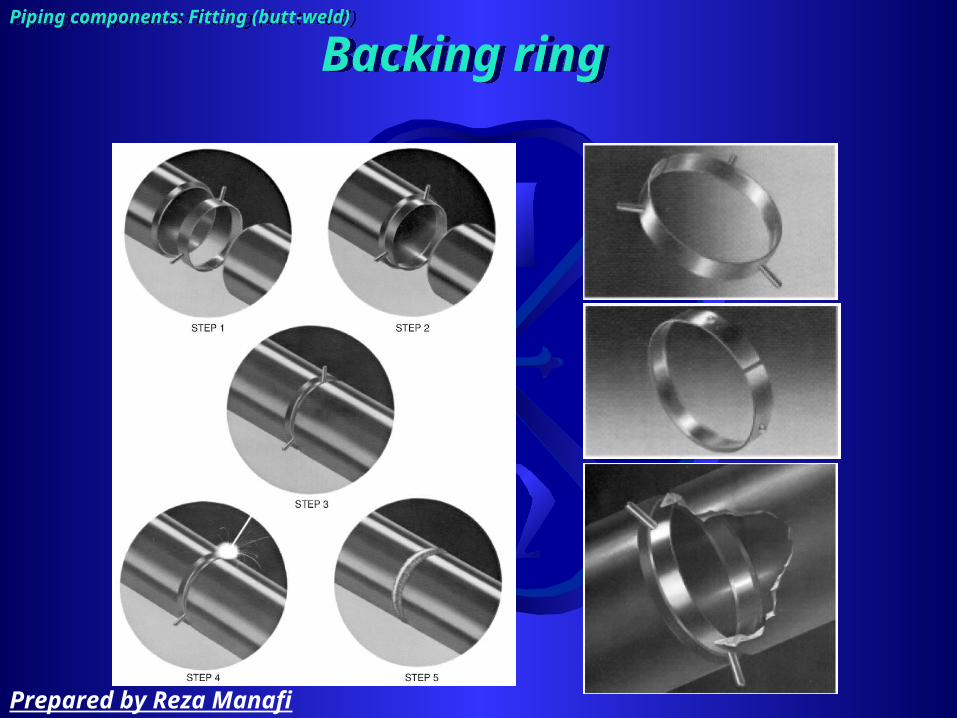
Backing ringBacking ringPiping components: Fitting (butt-weld)Piping components: Fitting (butt-weld)
Prepared by Reza Manafi

Elbow (90, 45)
– Long reduce• Curvature = 1 ½ NPS• Long tangent: straight
extension at one end– Short reduce
• curvature = NPS
Reducing elbow:
– 90– curvature = 1 ½ NPS larger end
Piping components: Fitting (butt-weld)Piping components: Fitting (butt-weld)
Prepared by Reza Manafi

Return:
– Curvature = 1 ½ NPS – Uses in:
• Vent on tanks
Bend:
– Curvature = 4 - 6 NPS– Made from seamless and ERW straight
pipe – Two methods used to making bend
• Hot• Cold
Piping components: Fitting (butt-weld)Piping components: Fitting (butt-weld)
Prepared by Reza Manafi

Miter
– 2 piece (pressure drop ≈ 4-6 LR elbow)– 3 piece (pressure drop ≈ 2 LR elbow)– Low pressure line, NPS > 10” & pressure drop not important– 90
Piping components: Fitting (butt-weld)Piping components: Fitting (butt-weld)
Prepared by Reza Manafi
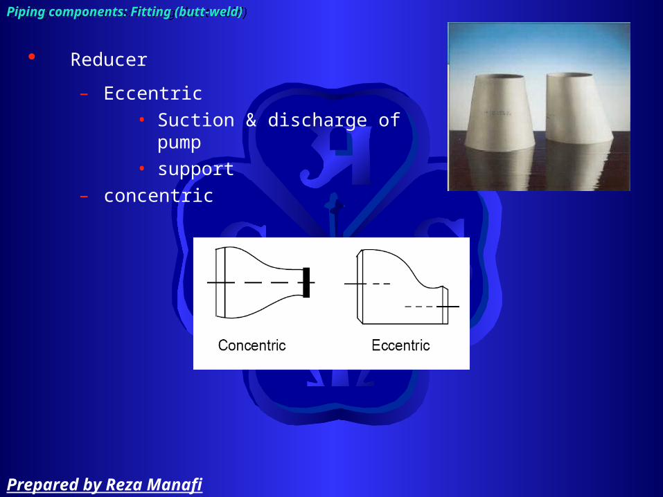
Reducer
– Eccentric• Suction & discharge of pump• support
– concentric
Piping components: Fitting (butt-weld)Piping components: Fitting (butt-weld)
Prepared by Reza Manafi

Sewage :
– connect butt-welded piping to smaller socket-weld or screwed
– Abrupt change of line size in butt-weld Type:• Eccentric• Concentric• Venturi: Allows smoother flow
Piping components: Fitting (butt-weld)Piping components: Fitting (butt-weld)
Prepared by Reza Manafi
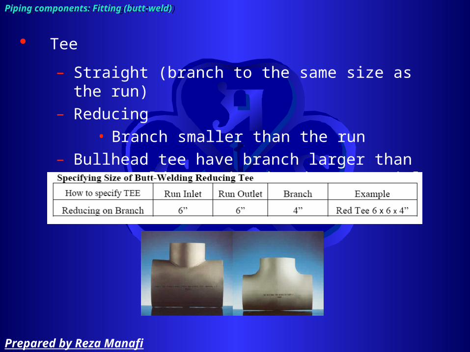
Tee
– Straight (branch to the same size as the run)– Reducing
• Branch smaller than the run– Bullhead tee have branch larger than run &
seldom used and made to special order
Piping components: Fitting (butt-weld)Piping components: Fitting (butt-weld)
Prepared by Reza Manafi

Cross
– Straight (branch to the same size as the run)– Reducing (rarely used)
Piping components: Fitting (butt-weld)Piping components: Fitting (butt-weld)
Prepared by Reza Manafi

Lateral (manufacture in factory)
– Run inlet × run outlet × branch × angle respect to outlet (6 × 6 × 4 × 45)
Shape nipple (use template)
– Manufacture at shop– Rarely use– 90, 45
45
Piping components: Fitting (butt-weld)Piping components: Fitting (butt-weld)
Prepared by Reza Manafi

Stub-in
– Welded directly in the side of the main pipe run– Least expensive– NPS ≥ 2”– Cab be reinforced
Piping components: Fitting (butt-weld)Piping components: Fitting (butt-weld)
Prepared by Reza Manafi

Weldolet
– Make a closer manifold that Tee– Full size– Reducing– Flat
• Are available for connecting to pipe caps and pressure vessel
Piping components: Fitting (butt-weld)Piping components: Fitting (butt-weld)
Prepared by Reza Manafi

Elbolet: reducing tangent branch on elbow
Latrolet : reducing, 45
Sweepolet
– Good flow pattern and optimum stress distribution
– 90 reducing from the main pipe
Piping components: Fitting (butt-weld)Piping components: Fitting (butt-weld)
Prepared by Reza Manafi

Closure
– Cap– Flat closure
Piping components: Fitting (butt-weld)Piping components: Fitting (butt-weld)
Prepared by Reza Manafi
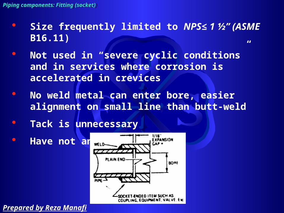
Size frequently limited to NPS≤ 1 ½” (ASME B16.11)
Not used in “severe cyclic conditions” and in services where corrosion is accelerated in crevices
No weld metal can enter bore, easier alignment on small line than butt-weld
Tack is unnecessary
Have not any leakage
Piping components: Fitting (socket)Piping components: Fitting (socket)
Prepared by Reza Manafi

Elbow (90, 45)
Piping components: Fitting (socket) Piping components: Fitting (socket)
Prepared by Reza Manafi

Return:
Piping components: Fitting (socket) Piping components: Fitting (socket)
Prepared by Reza Manafi

Reducer
Reducer insert
Piping components: Fitting (socket) Piping components: Fitting (socket)
Prepared by Reza Manafi

Sewage :
– Abrupt change of line size in butt-weld
Piping components: Fitting (socket) Piping components: Fitting (socket)
Prepared by Reza Manafi

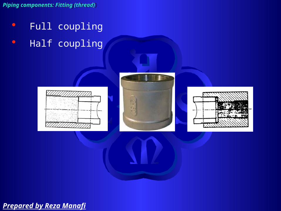
Full coupling
Half coupling
Piping components: Fitting (socket) Piping components: Fitting (socket)
Prepared by Reza Manafi

Union
Piping components: Fitting (socket) Piping components: Fitting (socket)
Prepared by Reza Manafi

Tee
Piping components: Fitting (socket) Piping components: Fitting (socket)
Prepared by Reza Manafi
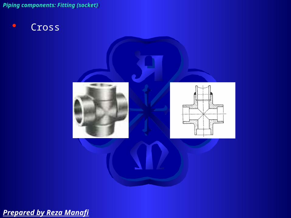
Cross
Piping components: Fitting (socket) Piping components: Fitting (socket)
Prepared by Reza Manafi

Lateral
Piping components: Fitting (socket) Piping components: Fitting (socket)
Prepared by Reza Manafi

Sockolet
Piping components: Fitting (socket) Piping components: Fitting (socket)
Prepared by Reza Manafi
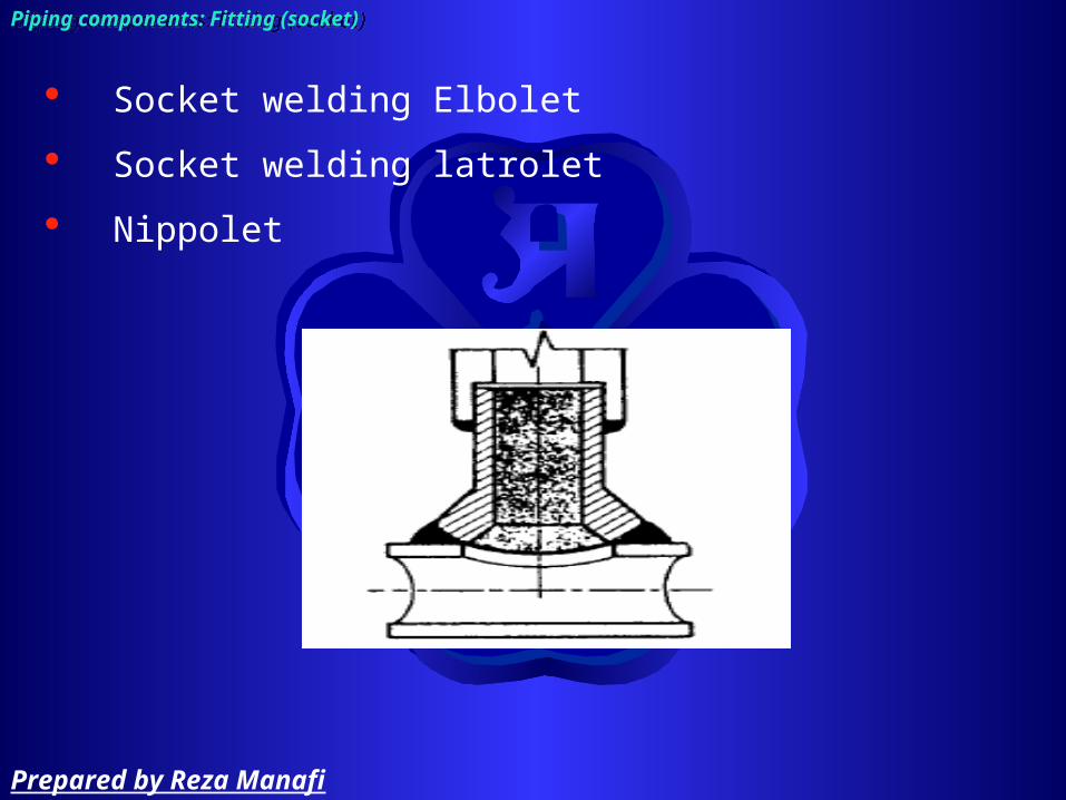
Socket welding Elbolet
Socket welding latrolet
Nippolet
Piping components: Fitting (socket) Piping components: Fitting (socket)
Prepared by Reza Manafi

Cap
Piping components: Fitting (socket) Piping components: Fitting (socket)
Prepared by Reza Manafi

Common materials
– Gray iron (ASME B16.4)– Malleable iron (ASME B16.3)– Steel (ASME B16.11)
─ Non-toxic, non-flammable, Generally not used where leaks cannot be tolerated
─ NPS ≤ 1 ½” , pressure rating < 600, temperature < 625
Piping components: Fitting (threaded = screwed)Piping components: Fitting (threaded = screwed)
Prepared by Reza Manafi

Elbow (90, 45)
Reducing elbow
Piping components: Fitting (thread)Piping components: Fitting (thread)
Prepared by Reza Manafi

Reducer
Reducer insert
Piping components: Fitting (thread)Piping components: Fitting (thread)
Prepared by Reza Manafi

Sewage nipple
Piping components: Fitting (thread)Piping components: Fitting (thread)
Prepared by Reza Manafi
Full coupling
Half coupling
Piping components: Fitting (thread)Piping components: Fitting (thread)
Prepared by Reza Manafi

Tee
Piping components: Fitting (thread)Piping components: Fitting (thread)
Prepared by Reza Manafi

Nipple
Piping components: Fitting (thread)Piping components: Fitting (thread)
Prepared by Reza Manafi
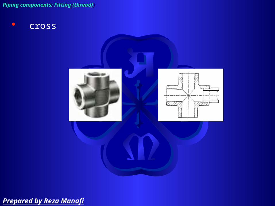
cross
Piping components: Fitting (thread)Piping components: Fitting (thread)
Prepared by Reza Manafi

lateral
Piping components: Fitting (thread)Piping components: Fitting (thread)
Prepared by Reza Manafi

Union
Piping components: Fitting (thread)Piping components: Fitting (thread)
Prepared by Reza Manafi

Hexagon bushing
Piping components: Fitting (thread)Piping components: Fitting (thread)
Prepared by Reza Manafi

Threadolet
Piping components: Fitting (thread)Piping components: Fitting (thread)
Prepared by Reza Manafi

Threaded elbolet
Threaded latrolet
Threaded nippolet
Piping components: Fitting (thread)Piping components: Fitting (thread)
Prepared by Reza Manafi

Closure
– Cap– plug
Piping components: Fitting (thread)Piping components: Fitting (thread)
Prepared by Reza Manafi

Piping components: FittingPiping components: Fitting
Flange used for
– Mate to equipment, vessels, valve, …– When need periodic cleaning– Flanges are normally used for pipe sizes above
NPS 1½”.
Prepared by Reza Manafi
Piping components: FittingPiping components: Fitting
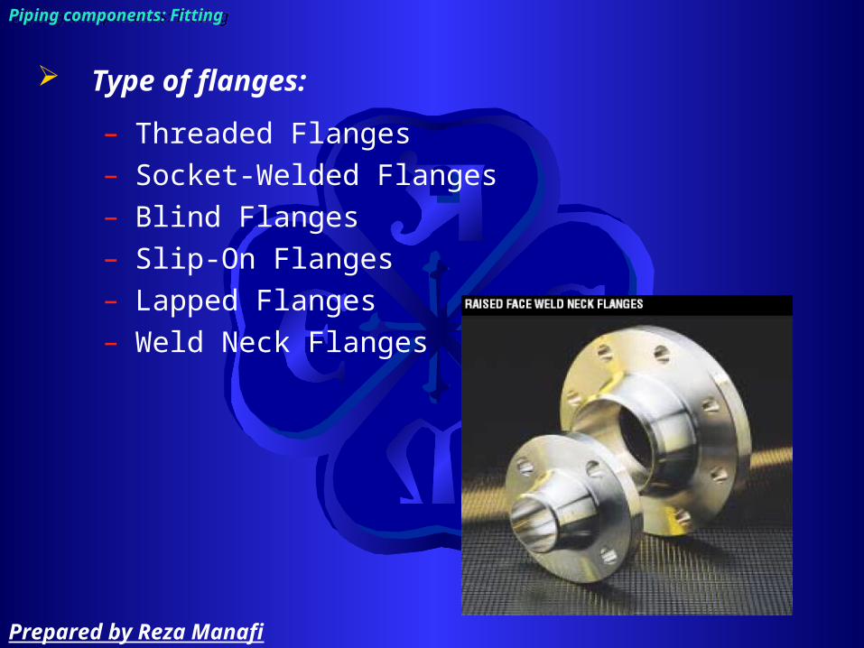
Type of flanges:
– Threaded Flanges– Socket-Welded Flanges– Blind Flanges– Slip-On Flanges– Lapped Flanges– Weld Neck Flanges
Prepared by Reza Manafi

Welding neck flange
– Regular– Long (used for vessel & equipment nozzle, rarely for
pipe Suitable where
– Extreme temperature– Shear– Impact and vibration
Stress apply
Piping components: Fitting (flange)Piping components: Fitting (flange)
Prepared by Reza Manafi

Slip-on flange
– Internal welds is slightly more subject to corrosion than the butt-weld (0 – 1/16”)
– Poor resistance to shock and vibration– Cheaper to buy, costlier to assemble– Strength under internal pressure 1/3 of corresponding
welding neck flange– Easier to align than the welding neck flange
Piping components: Fitting (flange)Piping components: Fitting (flange)
Prepared by Reza Manafi

Socket welding flange
Piping components: Fitting (flange)Piping components: Fitting (flange)
Prepared by Reza Manafi

Threaded flange
Piping components: Fitting (flange)Piping components: Fitting (flange)
Prepared by Reza Manafi

Reducing flange
– Specify by size of smaller pipe and outside diameter of flange to be mate
• Ex/ RED FLG 4” × 11” – Should not be used if abrupt transition would create
undesirable turbulence as at pump
Piping components: Fitting (flange)Piping components: Fitting (flange)
Prepared by Reza Manafi

Expander flange
– Reducer + welding neck flange– Increase pipe size to first or second large size
Piping components: Fitting (flange)Piping components: Fitting (flange)
Prepared by Reza Manafi

Lap joint (van stone) flange
– If stub and flange are of the same material they will be more expensive than a welding neck flange
– Economical for different material of stub and flange
Piping components: Fitting (flange)Piping components: Fitting (flange)
Prepared by Reza Manafi

Blind flange
Piping components: Fitting (flange)Piping components: Fitting (flange)
Prepared by Reza Manafi

Flageolet
Piping components: Fitting (flange)Piping components: Fitting (flange)
Prepared by Reza Manafi

Flange Facing Types
Flat Faced Raised Face Ring Joint
Piping components: Fitting (flange)Piping components: Fitting (flange)
Prepared by Reza Manafi

Flange Rating Class:
– pressure/temperature combinations– Seven classes (150, 300, 400, 600, 900, 1,500,
2,500)– Flange strength increases with class number– The material specifications are grouped within
Material Group Numbers.
Piping components: Fitting (flange)Piping components: Fitting (flange)
Prepared by Reza Manafi
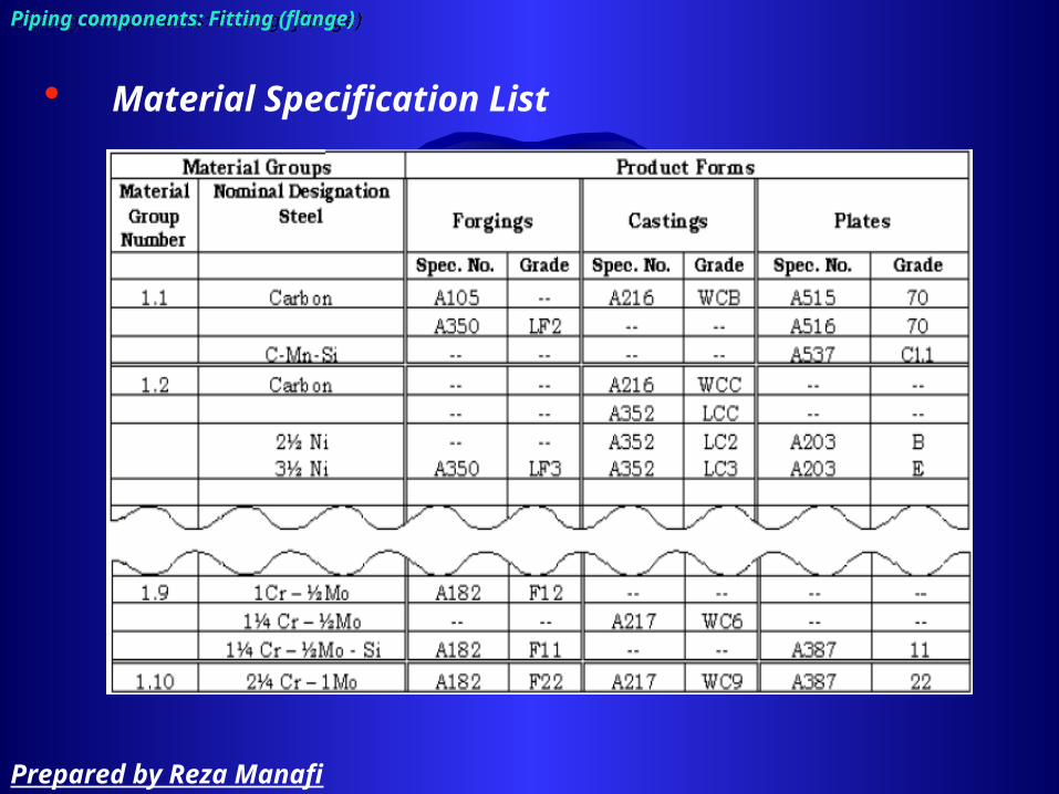
Material Specification List
Piping components: Fitting (flange)Piping components: Fitting (flange)
Prepared by Reza Manafi

Material and design temperature combinations that do not have a pressure indicated are not acceptable.
Pressure - Temperature Ratings
Piping components: Fitting (flange)Piping components: Fitting (flange)
Prepared by Reza Manafi

Flange Rating Class
Piping components: Fitting (flange)Piping components: Fitting (flange)
Prepared by Reza Manafi

Flange Rating Class
Piping components: Fitting (flange)Piping components: Fitting (flange)
Prepared by Reza Manafi

Flange Rating Class
Piping components: Fitting (flange)Piping components: Fitting (flange)
Prepared by Reza Manafi

Equipment Nozzle Load standards and Parameters
Piping components: Fitting (flange)Piping components: Fitting (flange)
Prepared by Reza Manafi
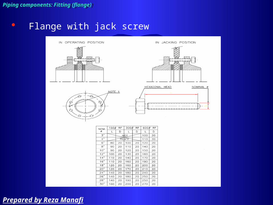
Flange with jack screw
Piping components: Fitting (flange)Piping components: Fitting (flange)
Prepared by Reza Manafi

Piping components: Fitting (piping specification)Piping components: Fitting (piping specification)
Prepared by Reza Manafi

Piping components: Fitting (gasket)Piping components: Fitting (gasket)
Prepared by Reza Manafi

Piping components: Fitting (branch connection chart)Piping components: Fitting (branch connection chart)
Prepared by Reza Manafi
Gasket:
– Resilient material– Inserted between flanges– Compressed by bolts to create seal– Commonly used types
• Sheet• Spiral wound• Solid metal ring• Insulation gasket
Piping components: Fitting (gasket)Piping components: Fitting (gasket)
Prepared by Reza Manafi

Sheet
Piping components: Fitting (gasket)Piping components: Fitting (gasket)
Prepared by Reza Manafi

Sheet
Piping components: Fitting (gasket)Piping components: Fitting (gasket)
Prepared by Reza Manafi
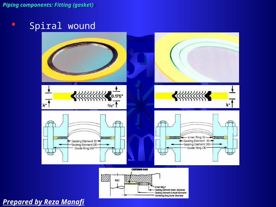
Spiral wound
Piping components: Fitting (gasket)Piping components: Fitting (gasket)
Prepared by Reza Manafi

Spiral wound
Piping components: Fitting (gasket)Piping components: Fitting (gasket)
Prepared by Reza Manafi

Spiral wound
Piping components: Fitting (gasket)Piping components: Fitting (gasket)
Prepared by Reza Manafi

Solid metal ring
Piping components: Fitting (gasket)Piping components: Fitting (gasket)
Prepared by Reza Manafi

Insulation gasket
Piping components: Fitting (gasket)Piping components: Fitting (gasket)
Prepared by Reza Manafi

Bolt type:
– Stud bolt• Easily remove if corroded• Material can be readily made
– Machine bolt Has to be strong enough to seat the gasket
Piping components: Fitting (bolt)Piping components: Fitting (bolt)
Prepared by Reza Manafi

Tightening arrangement
Piping components: Fitting (bolt)Piping components: Fitting (bolt)
Prepared by Reza Manafi

ASME B16.5, Pipe Flanges and Flanged Fittings (NPS ≤ 24”)
Piping components: FittingPiping components: Fitting
Prepared by Reza Manafi
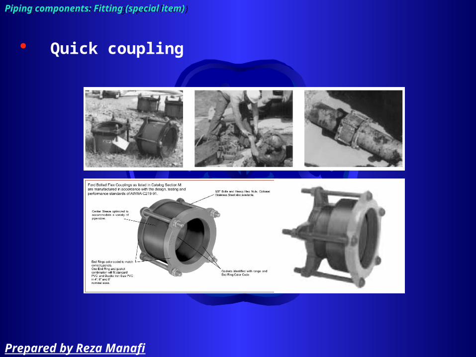
Quick coupling
Piping components: Fitting (special item)Piping components: Fitting (special item)
Prepared by Reza Manafi

Piping components: Fitting (special item)Piping components: Fitting (special item)
Flange coupling adaptor
Prepared by Reza Manafi
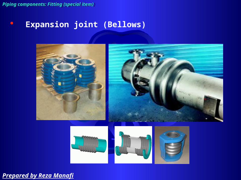
Piping components: Fitting (special item)Piping components: Fitting (special item)
Expansion joint (Bellows)
Prepared by Reza Manafi
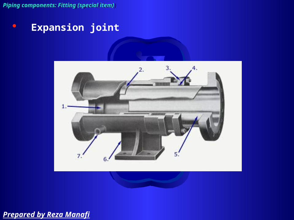
Piping components: Fitting (special item)Piping components: Fitting (special item)
Expansion joint
Prepared by Reza Manafi

Piping components: Fitting (special item)Piping components: Fitting (special item)
Flexible joint
Prepared by Reza Manafi

Piping components: Fitting (special item)Piping components: Fitting (special item)
Flexible joint
Prepared by Reza Manafi

Piping components: Fitting (special item)Piping components: Fitting (special item)
Double block & bleed
Prepared by Reza Manafi
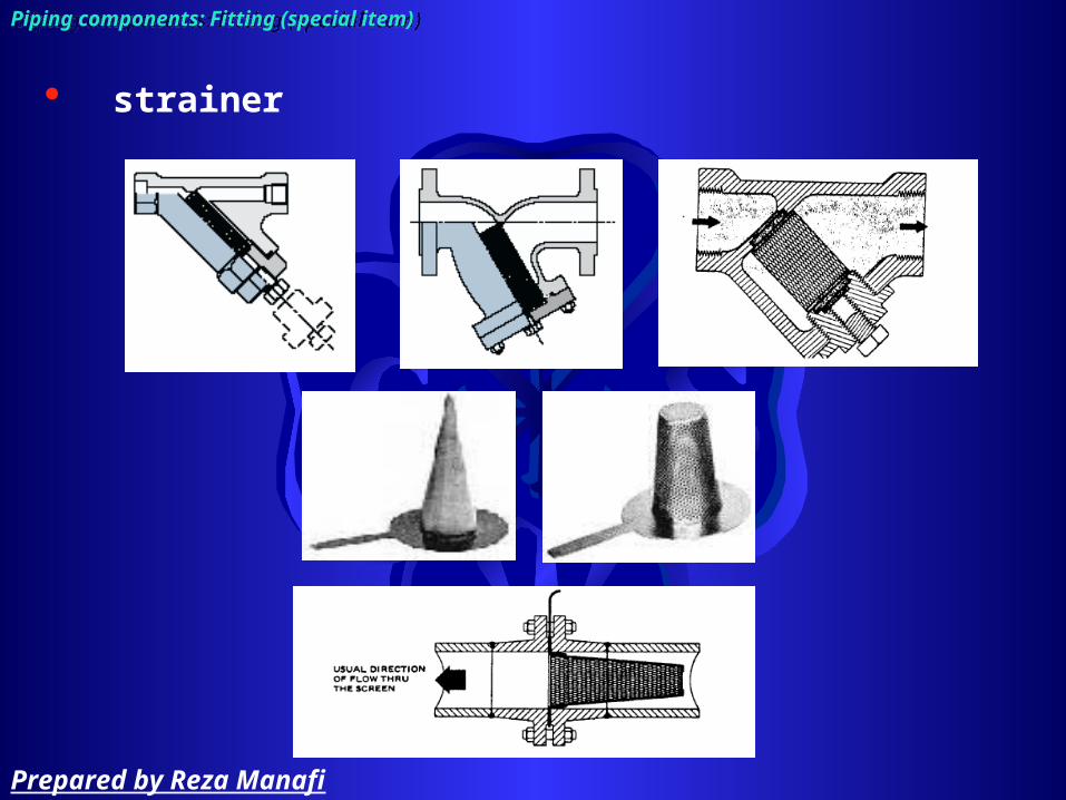
strainer
Piping components: Fitting (special item)Piping components: Fitting (special item)
Prepared by Reza Manafi

Spectacle blind
Piping components: Fitting (special item)Piping components: Fitting (special item)
Prepared by Reza Manafi

Piping components: Fitting (special item)Piping components: Fitting (special item)
Thermal sleeve & Queel
Prepared by Reza Manafi

Piping components: FittingPiping components: FittingPiping components: Fitting (special item)Piping components: Fitting (special item)
Bird screen
Prepared by Reza Manafi
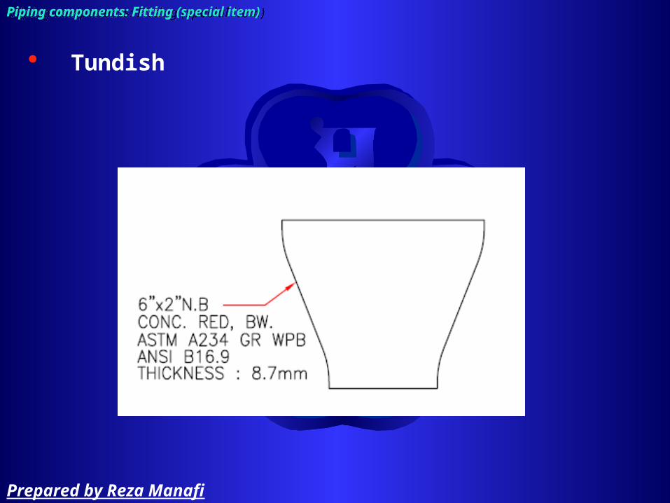
Piping components: FittingPiping components: FittingPiping components: Fitting (special item)Piping components: Fitting (special item)
Tundish
Prepared by Reza Manafi
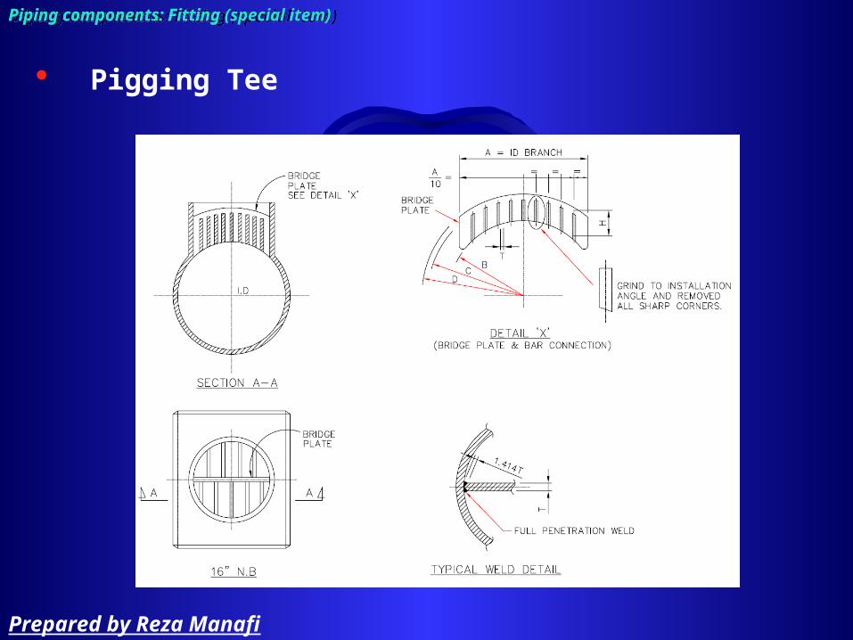
Piping components: FittingPiping components: FittingPiping components: Fitting (special item)Piping components: Fitting (special item)
Pigging Tee
Prepared by Reza Manafi

• RUPTURE DISKS OR BURST DIAPHRAGMS:• must be replaced after opening
Piping components: Fitting (special item)Piping components: Fitting (special item)
Prepared by Reza Manafi

ValvesValves
Piping components: valvePiping components: valve
Prepared by Reza Manafi

Valve are use for
– Controlling process and utility service– Isolating equipment or instrument for
maintenances– Discharge gas, vapor or liquid– Draining piping and equipment on
shutdown– Emergency shutdown
Piping components: valvePiping components: valve
Prepared by Reza Manafi

Classify valves according to functions:
– Block flow (On / Off)– Regulating (Throttle flow)– Checking (Prevent flow reversal)– Switching– Discharging (pressure relive valve)
Classify valves according to operating device:
– Manual– Hydraulic– Motor (electric and air operated)– Solenoid
Piping components: valvePiping components: valve
Prepared by Reza Manafi
Piping components: valvePiping components: valve
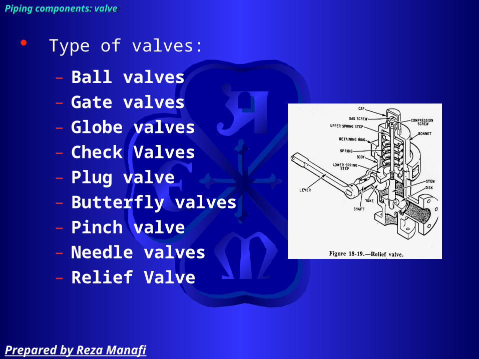
Type of valves:
– Ball valves– Gate valves– Globe valves– Check Valves – Plug valve– Butterfly valves– Pinch valve– Needle valves– Relief Valve
Prepared by Reza Manafi

Ball ValveBall Valve
Piping components: valvePiping components: valve
Prepared by Reza Manafi
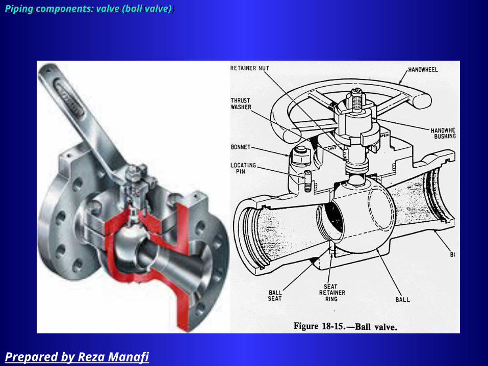
Piping components: valve (ball valve)Piping components: valve (ball valve)
Prepared by Reza Manafi
Piping components: valve (ball valve)Piping components: valve (ball valve)
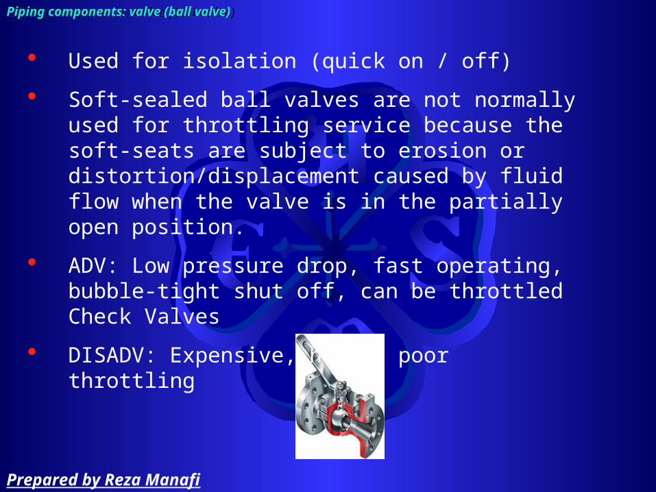
Used for isolation (quick on / off)
Soft-sealed ball valves are not normally used for throttling service because the soft-seats are subject to erosion or distortion/displacement caused by fluid flow when the valve is in the partially open position.
ADV: Low pressure drop, fast operating, bubble-tight shut off, can be throttled Check Valves
DISADV: Expensive, heavy, poor throttling
Prepared by Reza Manafi
Gate ValveGate Valve
Piping components: valvePiping components: valve
Prepared by Reza Manafi

Piping components: valve (gate valve)Piping components: valve (gate valve)
Prepared by Reza Manafi

Piping components: valve (gate valve)Piping components: valve (gate valve)
About 75% of all valves in process plants
an optimum engineering and economic choice for on or off service. (cutout or isolation valves)
ADV: small pressure drop across valve
DISADV: poor throttling characteristics
Prepared by Reza Manafi

Piping components: valve (gate valve)Piping components: valve (gate valve)
Prepared by Reza Manafi
Globe ValveGlobe Valve
Piping components: valvePiping components: valve
Prepared by Reza Manafi

Piping components: valve (globe valve)Piping components: valve (globe valve)
Prepared by Reza Manafi

Most economic for throttling flow and used for flow control
Can be hand-controlled
Provides “tight” shutoff
Not suitable for scraping or rodding
Too costly for on/off block operations
ADV: excellent throttling characteristics
DISADV: large pressure drop across the valve due to the flow restriction (thus more pumping power is required to move the fluid through the system.)
Piping components: valve (globe valve)Piping components: valve (globe valve)
Prepared by Reza Manafi

Piping components: valve (globe valve)Piping components: valve (globe valve)
Prepared by Reza Manafi

Check ValveCheck Valve
Piping components: valvePiping components: valve
Prepared by Reza Manafi
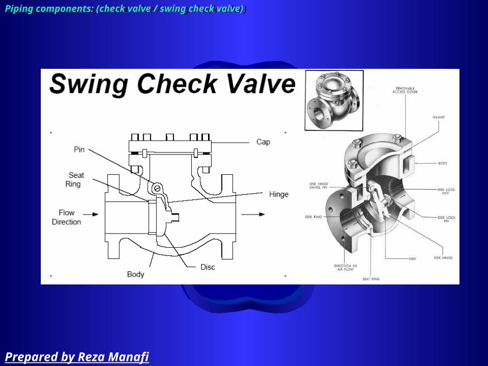
Piping components: (check valve / swing check valve)Piping components: (check valve / swing check valve)
Prepared by Reza Manafi

Simple design
Allows flow in one direction
Can not be used as an isolation valve
Piping components: (check valve / swing check valve)Piping components: (check valve / swing check valve)
Prepared by Reza Manafi

Piping components: (check valve / ball check valve)Piping components: (check valve / ball check valve)
Prepared by Reza Manafi

Their low cost usually makes them the first choice valves sized NPS 2 and smaller (available in sizes NPS ½ through 2)
Used when pressure drop is not a concern.
The basic types are the straight-through- and globe-type (90 change in direction)
Piping components: (check valve / ball check valve)Piping components: (check valve / ball check valve)
Prepared by Reza Manafi

Piping components: (check valve)Piping components: (check valve)
Prepared by Reza Manafi
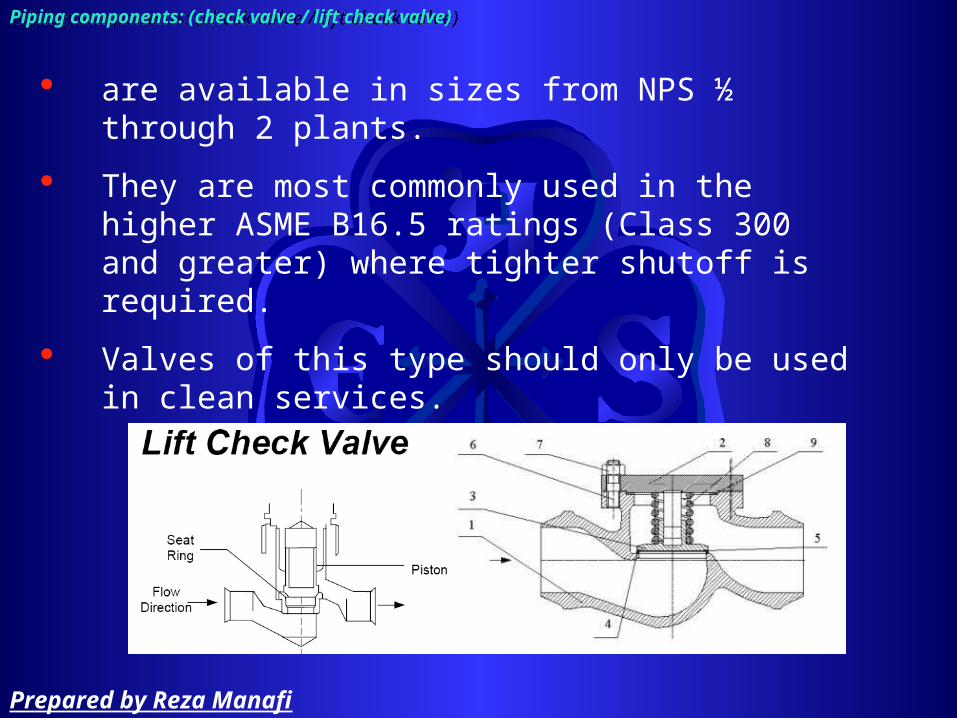
are available in sizes from NPS ½ through 2 plants.
They are most commonly used in the higher ASME B16.5 ratings (Class 300 and greater) where tighter shutoff is required.
Valves of this type should only be used in clean services.
Piping components: (check valve / lift check valve)Piping components: (check valve / lift check valve)
Prepared by Reza Manafi
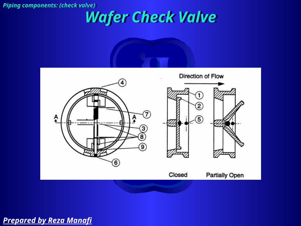
Wafer Check ValveWafer Check ValvePiping components: (check valve)Piping components: (check valve)
Prepared by Reza Manafi

Valves of this type are placed between pipe flanges and held in place by the compressive force between the flanges and transmitted through the gaskets.
Piping components: (check valve / wafer check valve)Piping components: (check valve / wafer check valve)
Prepared by Reza Manafi
Stop Check ValveStop Check ValvePiping components: (check valve)Piping components: (check valve)
Prepared by Reza Manafi

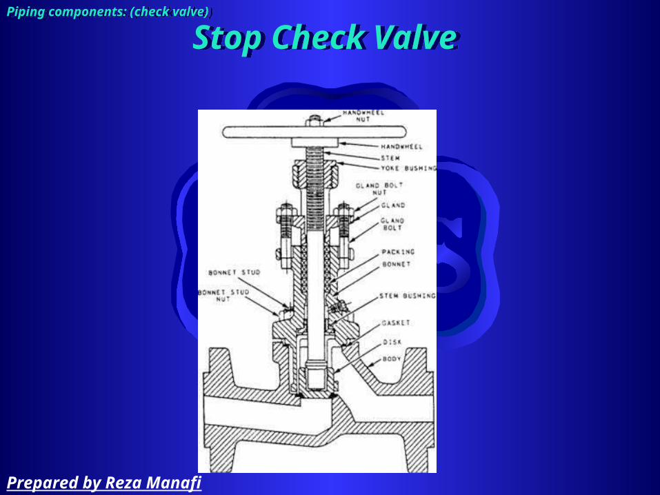
Piping components: (check valve / stop check valve)Piping components: (check valve / stop check valve)
Internals similar to a globe valve
Disc is not attached to the stem
Valve stem - long enough to hold the disc firmly against the seat
Stem raised - the disc can be opened by pressure on the inlet side
Can be used as an isolation valve as well as a check valve
Prepared by Reza Manafi

Piping components: (check valve)Piping components: (check valve)
Prepared by Reza Manafi
Function of check valve:
– Prevents flow reversal– Does not completely shut off reverse flow– Available in all sizes, ratings, materials– Valve type selection determined by
• Size limitations• Cost• Availability• Service
Piping components: (check valve)Piping components: (check valve)
Prepared by Reza Manafi

Plug ValvePlug Valve
Piping components: valvePiping components: valve
Prepared by Reza Manafi

Plug ValvePlug ValvePiping components: valve (plug valve)Piping components: valve (plug valve)
Prepared by Reza Manafi

Similar to ball valve
Piping components: valve (plug valve)Piping components: valve (plug valve)
Prepared by Reza Manafi

Butterfly ValveButterfly Valve
Piping components: valvePiping components: valve
Prepared by Reza Manafi

Butterfly ValveButterfly ValvePiping components: valve (butterfly valve)Piping components: valve (butterfly valve)
Prepared by Reza Manafi

Piping components: valve (butterfly valve)Piping components: valve (butterfly valve)
used as cutout/isolation valves
ADV: quick-acting low pressure drop across the valve, has adequate throttling characteristics
DISADV: only used for low press/low temp systems due to force involved in valve operation
Prepared by Reza Manafi

Pinch ValvePinch Valve
Piping components: valvePiping components: valve
Prepared by Reza Manafi

Pinch ValvePinch ValvePiping components: valve (pinch valve)Piping components: valve (pinch valve)
Prepared by Reza Manafi

Needle ValveNeedle Valve
Piping components: valvePiping components: valve
Prepared by Reza Manafi
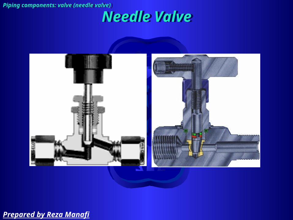
Needle ValveNeedle ValvePiping components: valve (needle valve)Piping components: valve (needle valve)
Prepared by Reza Manafi

Relive ValveRelive Valve
Piping components: valvePiping components: valve
Prepared by Reza Manafi

Relive ValveRelive ValvePiping components: valvePiping components: valve
Prepared by Reza Manafi
Piping components: valve (relive valve)Piping components: valve (relive valve)
special type of valve designed to operate automatically (self actuating) in a system overpressure condition (a protective feature in most systems)
most relief valves use an adjustable spring to determine lift pressure. System pressure opposes spring pressure, and when pressure is high enough, the valve will open against spring pressure and port the fluid to another location (typically, overboard for ‘safe’ fluids)
Type of relive valve:
– Relief Valve - liquid systems
– Safety Valve - gas and vapor systems
– Safety Relief Valve - liquid and/or vapor systems
Prepared by Reza Manafi

Interlock sequenceInterlock sequencePiping components: valve (interlock)Piping components: valve (interlock)
close
Prepared by Reza Manafi

Parts of valves:
– disk:• The moving part directly affecting the flow
– seat:• Non-moving part that disk bear on it
– Metallic– Non-metallic (elastomer)
– port:• Maximum internal opening for flow when the valve is
fully open– Stem:
• Move the disk– Handwheel:
• Rise with the stem• Stem rise thru the handwheel
Piping components: valve (parts)Piping components: valve (parts)
Prepared by Reza Manafi

Piping components: valve (result)Piping components: valve (result)
Prepared by Reza Manafi

General procedure for valve selection.
– Identify design information including pressure and temperature, valve function, material, etc.
– Identify potentially appropriate valve types and components based on application and function (i.e., block, throttle, or reverse flow prevention).
Piping components: valve (valve selection process)Piping components: valve (valve selection process)
Prepared by Reza Manafi
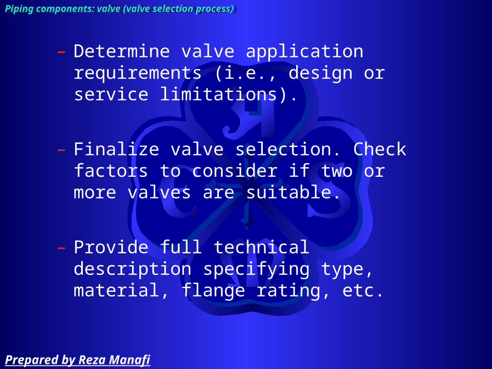
– Determine valve application requirements (i.e., design or service limitations).
– Finalize valve selection. Check factors to consider if two or more valves are suitable.
– Provide full technical description specifying type, material, flange rating, etc.
Piping components: valve (valve selection process)Piping components: valve (valve selection process)
Prepared by Reza Manafi
Val
ve d
ata
shee
tV
alve
dat
a sh
eet
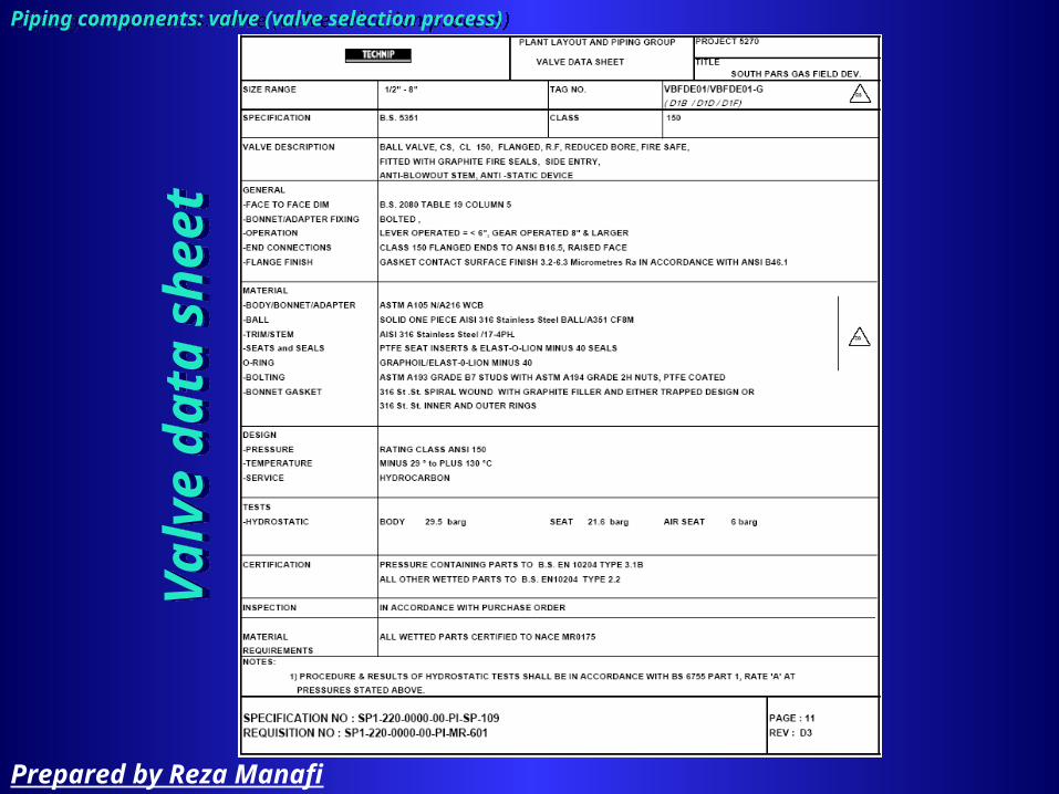
Piping components: valve (valve selection process)Piping components: valve (valve selection process)
Prepared by Reza Manafi

According to ANSI, leakage classify by class
(I, II, III, IV, VI)
Piping components: valve (leakage classification)Piping components: valve (leakage classification)
Prepared by Reza Manafi

Pipe Supports and RestraintsPipe Supports and Restraints
Prepared by Reza Manafi

Function of supports and restraints:
– To carry load– To ensure that material is not stressed beyond a
safe limit– Holdup of liquid can occurred due to pipe sagging
(allow draining)– To permit thermal expansion– To withstand and dampen vibrational forces applied
to the piping
Piping components: pipe supports and restraintsPiping components: pipe supports and restraints
Prepared by Reza Manafi

Supports:
– Absorb system weight– Reduce:
• longitudinal pipe stress• pipe sag• end point reaction loads
Piping components: pipe supports and restraintsPiping components: pipe supports and restraints
Prepared by Reza Manafi

Restraints
– Control, limit, redirect thermal movement• Reduce thermal stress• Reduce loads on equipment connections
– Absorb imposed loads• Wind• Earthquake• Slug flow• Water hammer• Flow induced-vibration
Piping components: pipe supports and restraintsPiping components: pipe supports and restraints
Prepared by Reza Manafi

Support and Restraint Selection Factors:
– Weight load– Available attachment clearance– Availability of structural steel– Direction of loads and/or movement– Design temperature– Vertical thermal movement at supports
Piping components: pipe supports and restraintsPiping components: pipe supports and restraints
Prepared by Reza Manafi

Piping components: pipe supports and restraints (rigid support)Piping components: pipe supports and restraints (rigid support)
Prepared by Reza Manafi

Piping components: pipe supports and restraints (hanger support)Piping components: pipe supports and restraints (hanger support)
Prepared by Reza Manafi
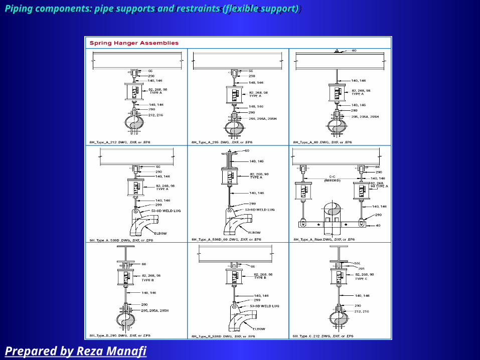
Piping components: pipe supports and restraints (flexible support)Piping components: pipe supports and restraints (flexible support)
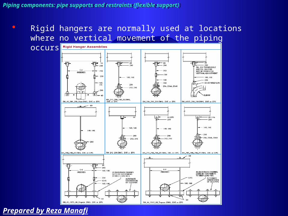
Rigid hangers are normally used at locations where no vertical movement of the piping occurs.
Prepared by Reza Manafi

Piping components: pipe supports and restraints (flexible support)Piping components: pipe supports and restraints (flexible support)
Prepared by Reza Manafi

Flexible SupportsFlexible Supports
Piping components: pipe supports and restraints (flexible support)Piping components: pipe supports and restraints (flexible support)
Prepared by Reza Manafi

Piping components: pipe supports and restraints (flexible support)Piping components: pipe supports and restraints (flexible support)
Prepared by Reza Manafi
Flexible SupportsFlexible Supports
Piping components: pipe supports and restraints (flexible support)Piping components: pipe supports and restraints (flexible support)
Prepared by Reza Manafi

Flexible SupportsFlexible Supports
Piping components: pipe supports and restraints (flexible support)Piping components: pipe supports and restraints (flexible support)
Prepared by Reza Manafi
Piping components: pipe supports and restraints (flexible support)Piping components: pipe supports and restraints (flexible support)
Prepared by Reza Manafi

Piping components: pipe supports and restraints (flexible support)Piping components: pipe supports and restraints (flexible support)
Prepared by Reza Manafi
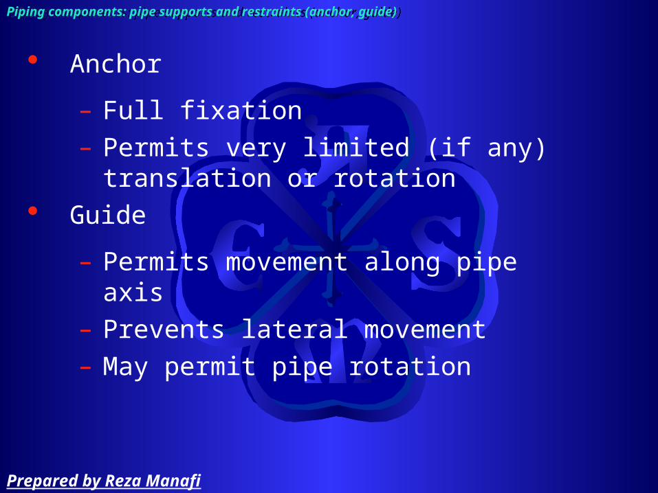
Anchor
– Full fixation– Permits very limited (if any) translation or
rotation Guide
– Permits movement along pipe axis– Prevents lateral movement– May permit pipe rotation
Piping components: pipe supports and restraints (anchor, guide)Piping components: pipe supports and restraints (anchor, guide)
Prepared by Reza Manafi
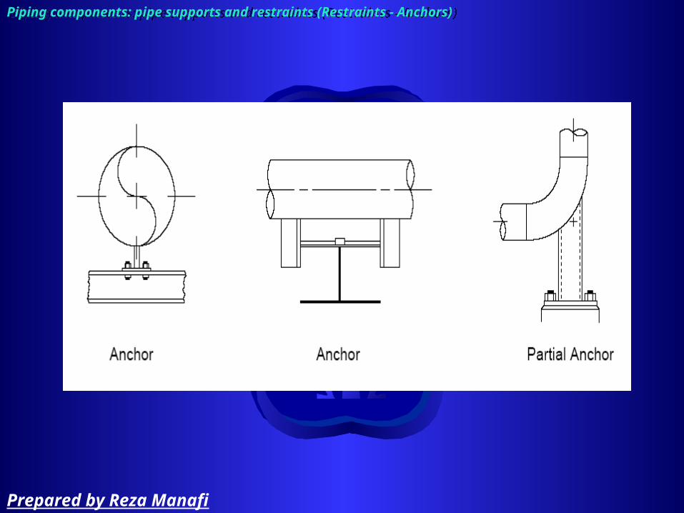
Piping components: pipe supports and restraints (Restraints - Anchors)Piping components: pipe supports and restraints (Restraints - Anchors)
Prepared by Reza Manafi

Piping components: pipe supports and restraints (Restraints - Guide)Piping components: pipe supports and restraints (Restraints - Guide)
Prepared by Reza Manafi

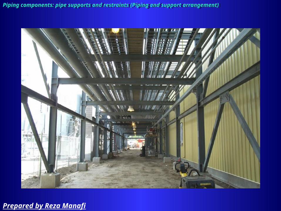
Piping can be arranged
– On piperacks
– Near grade on sleeper
– In trench
– Near steelwork or equipment
Piping components: pipe supports and restraints (Piping and support arrangement)Piping components: pipe supports and restraints (Piping and support arrangement)
Prepared by Reza Manafi
Piping components: pipe supports and restraints (Piping and support arrangement)Piping components: pipe supports and restraints (Piping and support arrangement)
Prepared by Reza Manafi
Piping components: pipe supports and restraints (Piping and support arrangement)Piping components: pipe supports and restraints (Piping and support arrangement)
Prepared by Reza Manafi

Piping components: pipe supports and restraints (Piping and support arrangement)Piping components: pipe supports and restraints (Piping and support arrangement)
Prepared by Reza Manafi

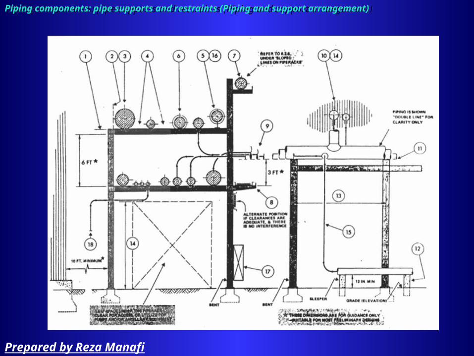
Pipeway:
– Is the space allocated for routing several parallel adjacent lines
– Group lines in pipeway
Piperack
– Is a structure in the pipeway for carrying pipes and is usually fabricated from Steel, Concrete & steel, also provide protected location for ancillary equipment (pump, utility station, …)
– Piperack shape termed tee-head support
Piping components: pipe supports and restraints (Piping and support arrangement / support definition)Piping components: pipe supports and restraints (Piping and support arrangement / support definition)
Prepared by Reza Manafi
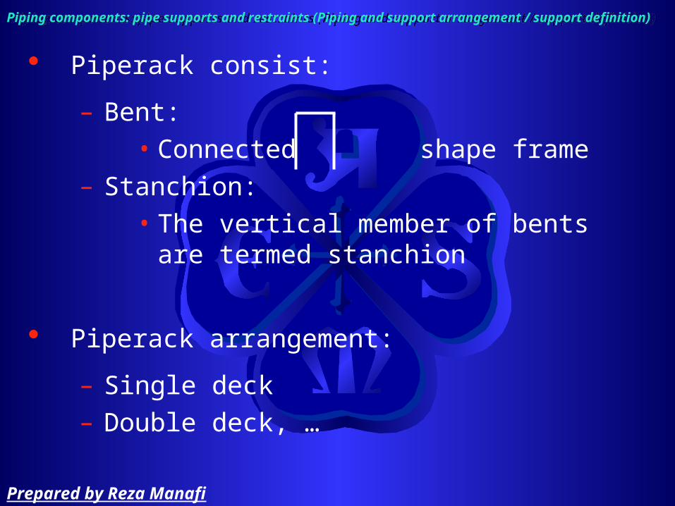
Piperack consist:
– Bent:• Connected shape frame
– Stanchion:• The vertical member of bents are
termed stanchion
Piperack arrangement:
– Single deck– Double deck, …
Piping components: pipe supports and restraints (Piping and support arrangement / support definition)Piping components: pipe supports and restraints (Piping and support arrangement / support definition)
Prepared by Reza Manafi

Arrangement of pipe on support:
– Usually 2” < NPS < 12” mounted on piperack and larger pipes are mounted on sleeper
– Mounted large diameter pipe near stanchion for uniform distribution of load
Piping components: pipe supports and restraints (Piping and support arrangement)Piping components: pipe supports and restraints (Piping and support arrangement)
Prepared by Reza Manafi

– Hot pipe usually insulated and mounted on shoes
Piping components: pipe supports and restraints (Piping and support arrangement)Piping components: pipe supports and restraints (Piping and support arrangement)
Prepared by Reza Manafi

– Other type of shoes
Piping components: pipe supports and restraints (Piping and support arrangement)Piping components: pipe supports and restraints (Piping and support arrangement)
Prepared by Reza Manafi
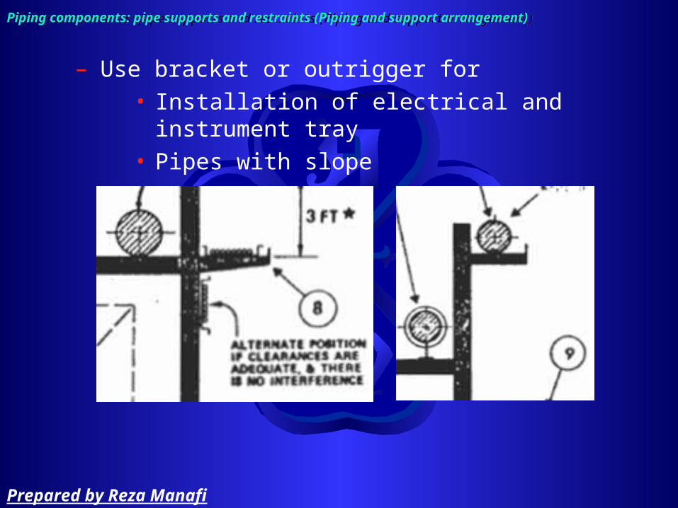
– Use bracket or outrigger for • Installation of electrical and instrument tray• Pipes with slope
Piping components: pipe supports and restraints (Piping and support arrangement)Piping components: pipe supports and restraints (Piping and support arrangement)
Prepared by Reza Manafi

– Group requiring expansion loop at one side of the pipe rack
– Design hanger for 2 ½” and larger pipe
Piping components: pipe supports and restraints (Piping and support arrangement)Piping components: pipe supports and restraints (Piping and support arrangement)
Prepared by Reza Manafi

– For better stress distribution in the pipe wall, saddle used on large line and used for lines that twist over when moving
Piping components: pipe supports and restraints (Piping and support arrangement)Piping components: pipe supports and restraints (Piping and support arrangement)
Prepared by Reza Manafi

– Provide guide for long straight pipes subject to thermal movement
Piping components: pipe supports and restraints (Piping and support arrangement)Piping components: pipe supports and restraints (Piping and support arrangement)
Prepared by Reza Manafi

– The smallest size of pipe run on a piperack 2”
– If necessary, suspend pipe smaller 2” from 4” and larger
– For making horizontal branch, change height of pipe
Piping components: pipe supports and restraints (Piping and support arrangement)Piping components: pipe supports and restraints (Piping and support arrangement)
Prepared by Reza Manafi

– The most economic beam section desired for the piperack
– If more room is needed, make double or triple piperack
Piping components: pipe supports and restraints (Piping and support arrangement)Piping components: pipe supports and restraints (Piping and support arrangement)
20 -25 ft
> 6 ft
Prepared by Reza Manafi
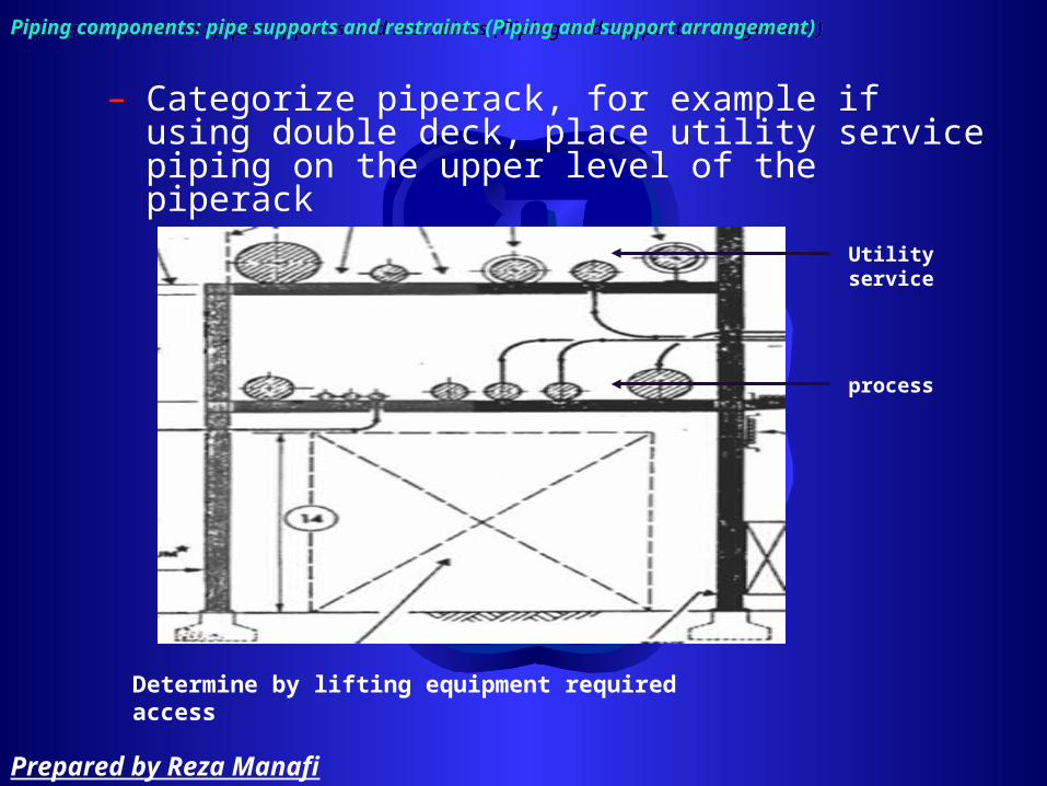
– Categorize piperack, for example if using double deck, place utility service piping on the upper level of the piperack
Piping components: pipe supports and restraints (Piping and support arrangement)Piping components: pipe supports and restraints (Piping and support arrangement)
Utility service
process
Determine by lifting equipment required access
Prepared by Reza Manafi

– Don’t install pipe on stanchion, this will prevent adding another deck
– Consider sufficient space beside piperack
Piping components: pipe supports and restraints (Piping and support arrangement)Piping components: pipe supports and restraints (Piping and support arrangement)
10 ft
Prepared by Reza Manafi

– Ensure that nozzles on equipment are free from transmitted by the piping
– Equipment suppliers will state max. loading permissible at nozzles
Piping components: pipe supports and restraints (Piping and support arrangement)Piping components: pipe supports and restraints (Piping and support arrangement)
Prepared by Reza Manafi

– Dummy leg length
Piping components: pipe supports and restraints (Piping and support arrangement)Piping components: pipe supports and restraints (Piping and support arrangement)
Prepared by Reza Manafi

– For line smaller than 2” and non-critical arrange supports in the field
– Pocketing of liquid due to sagging can be eliminated by sloping the line so that the difference in height between adjacent supports is at least equal to triple deflection at the midpoint
– As a rule of thumb, spans for insulated lines should be reduced by approximately %30 from those for uninsulated pipes
Piping components: pipe supports and restraints (Piping and support arrangement)Piping components: pipe supports and restraints (Piping and support arrangement)
Prepared by Reza Manafi
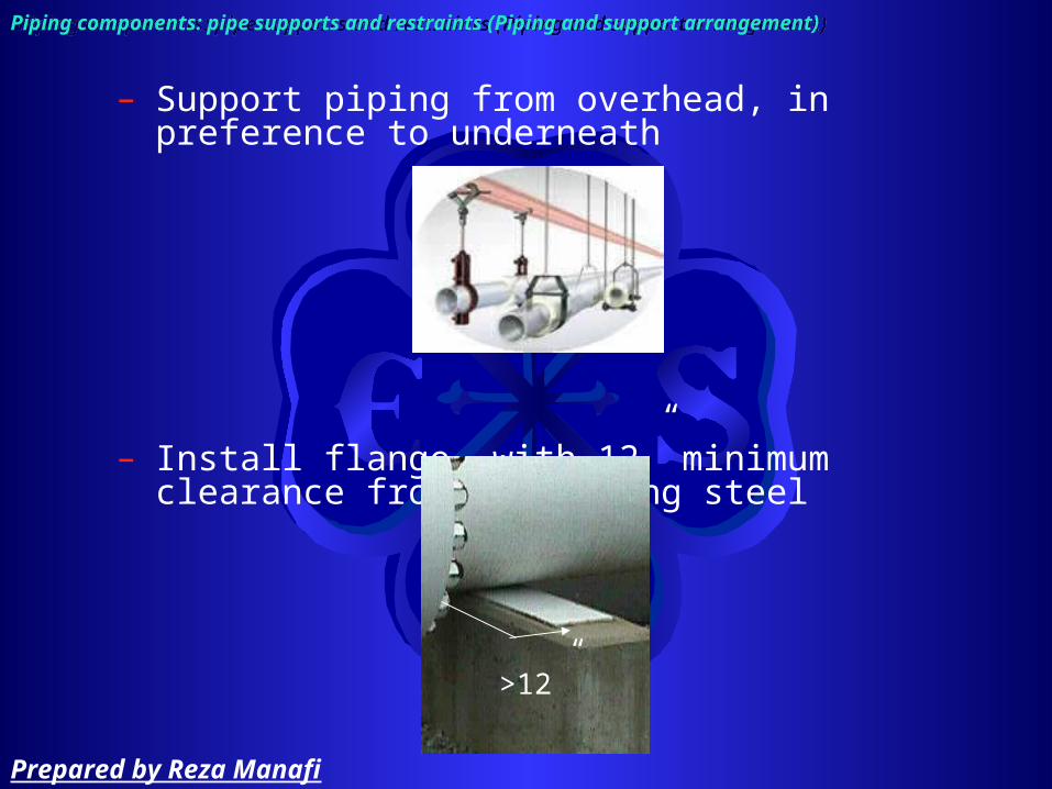
– Support piping from overhead, in preference to underneath
– Install flange, with 12” minimum clearance from supporting steel
>12”
Piping components: pipe supports and restraints (Piping and support arrangement)Piping components: pipe supports and restraints (Piping and support arrangement)
Prepared by Reza Manafi

– Keep weld joints at least 3” from supporting steel or other obstruction
– To carry the weight of the piping use a FOS = 3
– In general, one hanger or other support should be specified for each side of a valve.
Piping components: pipe supports and restraints (Piping and support arrangement)Piping components: pipe supports and restraints (Piping and support arrangement)
>3”
Prepared by Reza Manafi

– Field support• For line smaller than 2” and non-critical, arrange
supports in the field
– Finding location of support
Piping components: pipe supports and restraints (Piping and support arrangement)Piping components: pipe supports and restraints (Piping and support arrangement)
Prepared by Reza Manafi

Piping components: pipe supports and restraints (piping support document)Piping components: pipe supports and restraints (piping support document)
Prepared by Reza Manafi
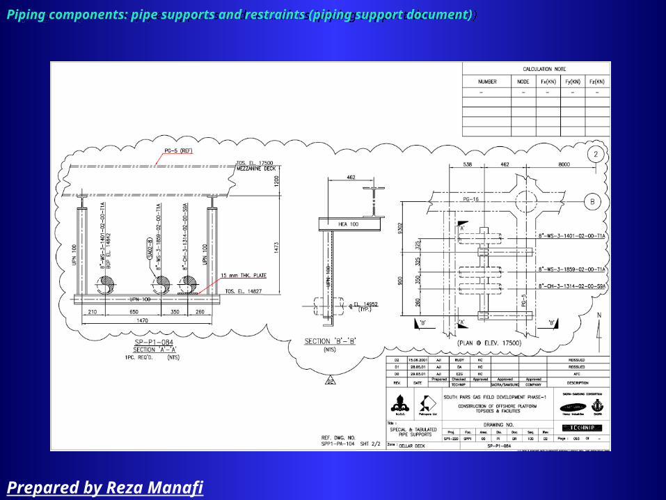
Piping components: pipe supports and restraints (piping support document)Piping components: pipe supports and restraints (piping support document)
Prepared by Reza Manafi

Piping components: pipe supports and restraints (piping support drawing)Piping components: pipe supports and restraints (piping support drawing)
Prepared by Reza Manafi

Piping Drawing
Prepared by Reza Manafi

The main purpose of a drawing is to communicate information in a simple and explicit way for construction apart from specification
Pipe represent by
– Single line:• Only centerline of the pipe is drawn
– Double line:• Very time-consuming• Difficult to read
Piping drawings:Piping drawings:
Prepared by Reza Manafi

Three type of drawing that developed from schematic (Block Flow Diagram (BFD)) diagram are:
– Process Flow Diagram (PFD)
– Piping & Instrument Diagram (P&ID)
– Piping drawing
Piping drawings:Piping drawings:
Prepared by Reza Manafi

Block Flow DiagramBFD
Prepared by Reza Manafi
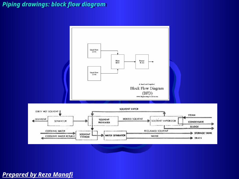
Piping drawings: block flow diagramPiping drawings: block flow diagram
Prepared by Reza Manafi

A Block Flow Diagram - BFD, is a schematic illustration of the major process.The block or rectangles used represent a unit operation. The blocks are connected by straight lines which represent the process flow streams which flow between the units. These process flow streams may be mixtures of liquids, gases and solids flowing in pipes or ducts, or solids.
Piping drawings: block flow diagramPiping drawings: block flow diagram
Prepared by Reza Manafi

In order to prepare block flow diagrams a number of rules should be followed:
– unit operations such as mixers, separators, reactors, distillation columns and heat exchangers are usually denoted by a simple block or rectangle.
– groups of unit operations may be noted by a single block or rectangle.
– process flow streams flowing into and out of the blocks are represented by neatly drawn straight lines. These lines should either be horizontal or vertical.
– the direction of flow of each of the process flow streams must be clearly indicated by arrows.
– flow streams should be numbered sequentially in a logical order.
– unit operations (i.e., blocks) should be labeled. – where possible the diagram should be arranged so that
the process material flows from left to right, with upstream units on the left and downstream units on the right.
Piping drawings: block flow diagramPiping drawings: block flow diagram
Prepared by Reza Manafi
Process Flow DiagramPFD
Prepared by Reza Manafi

Piping drawings: process flow diagramPiping drawings: process flow diagram
Prepared by Reza Manafi

Piping drawings: process flow diagramPiping drawings: process flow diagram
Prepared by Reza Manafi

A Process Flow Diagram - PFD, is a schematic illustration of the system.PFD's shows the relationships between the major components in the system. PFD also tabulate process design values for the components in different operating modes, typical minimum, normal and maximum. PFD's do not show minor components, piping systems, piping ratings, standby equipment
– It is advisable to draw equipment that is operated cyclically
Piping drawings: process flow diagramPiping drawings: process flow diagram
Prepared by Reza Manafi
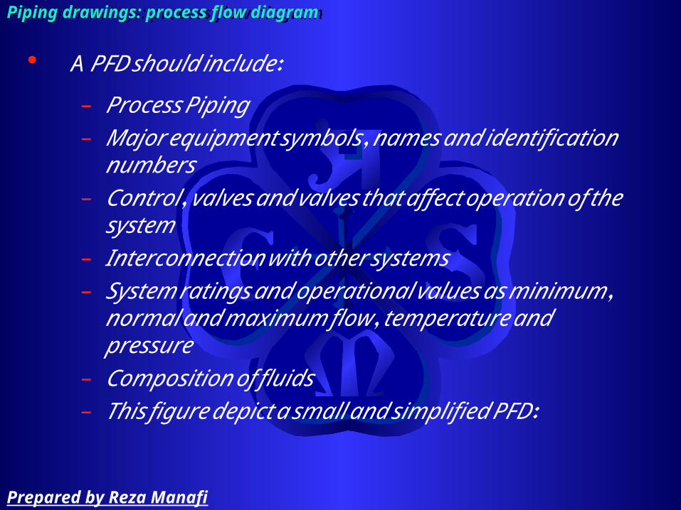
A PFD should include:
– Process Piping – Major equipment symbols, names and identification
numbers – Control, valves and valves that affect operation of
the system – Interconnection with other systems – System ratings and operational values as
minimum, normal and maximum flow, temperature and pressure
– Composition of fluids – This figure depict a small and simplified PFD:
Piping drawings: process flow diagramPiping drawings: process flow diagram
Prepared by Reza Manafi
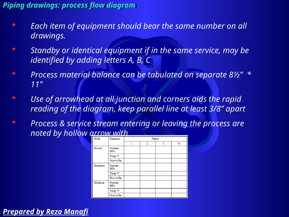
Each item of equipment should bear the same number on all drawings.
Standby or identical equipment if in the same service, may be identified by adding letters A, B, C
Process material balance can be tabulated on separate 8½” * 11”
Use of arrowhead at all junction and corners aids the rapid reading of the diagram, keep parallel line at least 3/8” apart
Process & service stream entering or leaving the process are noted by hollow arrow with
Piping drawings: process flow diagramPiping drawings: process flow diagram
Prepared by Reza Manafi

Piping and Instrumentation DiagramP&ID
Prepared by Reza Manafi

Piping drawings: piping and instrumentation diagramPiping drawings: piping and instrumentation diagram
Prepared by Reza Manafi

A Piping and Instrumentation Diagram - P&ID, is a schematic illustration of functional relationship of piping, instrumentation and system equipment components.P&ID shows all of piping including the physical sequence of branches, reducers, valves, equipment, instrumentation and control interlocks. The P&ID are used to operate the process system.
Piping drawings: piping and instrumentation diagramPiping drawings: piping and instrumentation diagram
Prepared by Reza Manafi

A P&ID should include:
– Instrumentation and designations – Mechanical equipment with names and numbers – All valves and their identifications – Process piping, sizes and identification – Miscellaneous - vents, drains, special fittings,
sampling lines, reducers and increasers – Flow directions – Interconnections – Control inputs and outputs, interlocks
Piping drawings: piping and instrumentation diagramPiping drawings: piping and instrumentation diagram
Prepared by Reza Manafi

Preferably draw all valves with the same size ¼” long
Piping drawings: piping and instrumentation diagramPiping drawings: piping and instrumentation diagram
Prepared by Reza Manafi

Draw instrument identification balloons 7/16” diameter
Draw square with 3/8” width
Piping drawings: piping and instrumentation diagramPiping drawings: piping and instrumentation diagram
Prepared by Reza Manafi

Allocate new number to branch
A typical note may be used to describe multiple piece of identical equipment in the same service
Special point for design and operation procedure are noted – such as line which need to be sloped for gravity flow, line which need careful cleaning, …
Piping drawings: piping and instrumentation diagramPiping drawings: piping and instrumentation diagram
Prepared by Reza Manafi

Terminate the number at major number of a equipment such as tank, pressure vessel, mixer or any equipment carrying an individual equipment number
Show and tag process and service valve with size and identification number
Piping drawings: piping and instrumentation diagramPiping drawings: piping and instrumentation diagram
Prepared by Reza Manafi
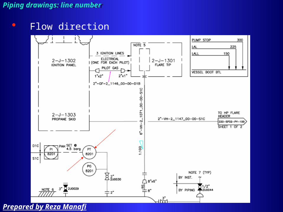
Flow direction
Piping drawings: line numberPiping drawings: line number
Prepared by Reza Manafi

Standby and parallel equipment are shown
Dripleg are not shown but steam trap are shown
vent and drain to be used for hydrostatic testing are not shown
Insulation, insulation thickness and tracing are shown
Piping drawings: piping and instrumentation diagramPiping drawings: piping and instrumentation diagram
Prepared by Reza Manafi

Drawing component
Prepared by Reza Manafi

Drawing components include:
– Title block– Revision– Key plan – Reference drawings– Legend– Important notes– Graphic reference point– line number– Flow directions – connections
Piping drawings: drawing componentPiping drawings: drawing component
Prepared by Reza Manafi

Title block
Piping drawings: drawing component (title block)Piping drawings: drawing component (title block)
Prepared by Reza Manafi

Space for revision
Piping drawings: drawing component (space for revision)Piping drawings: drawing component (space for revision)
Prepared by Reza Manafi
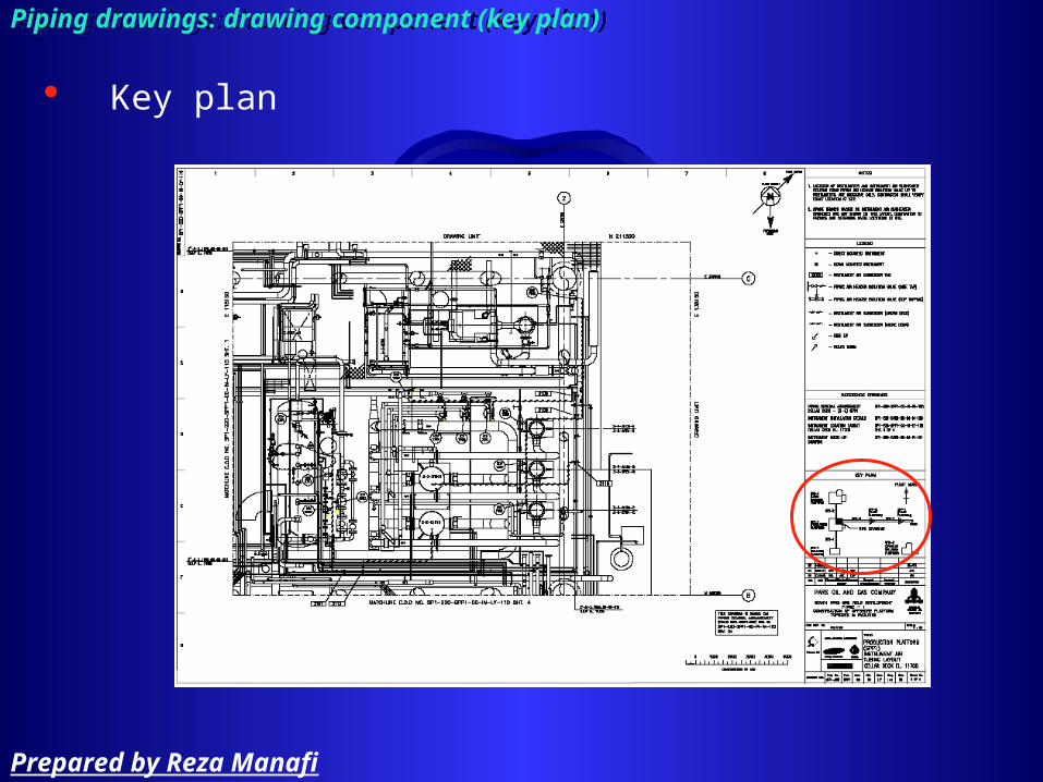
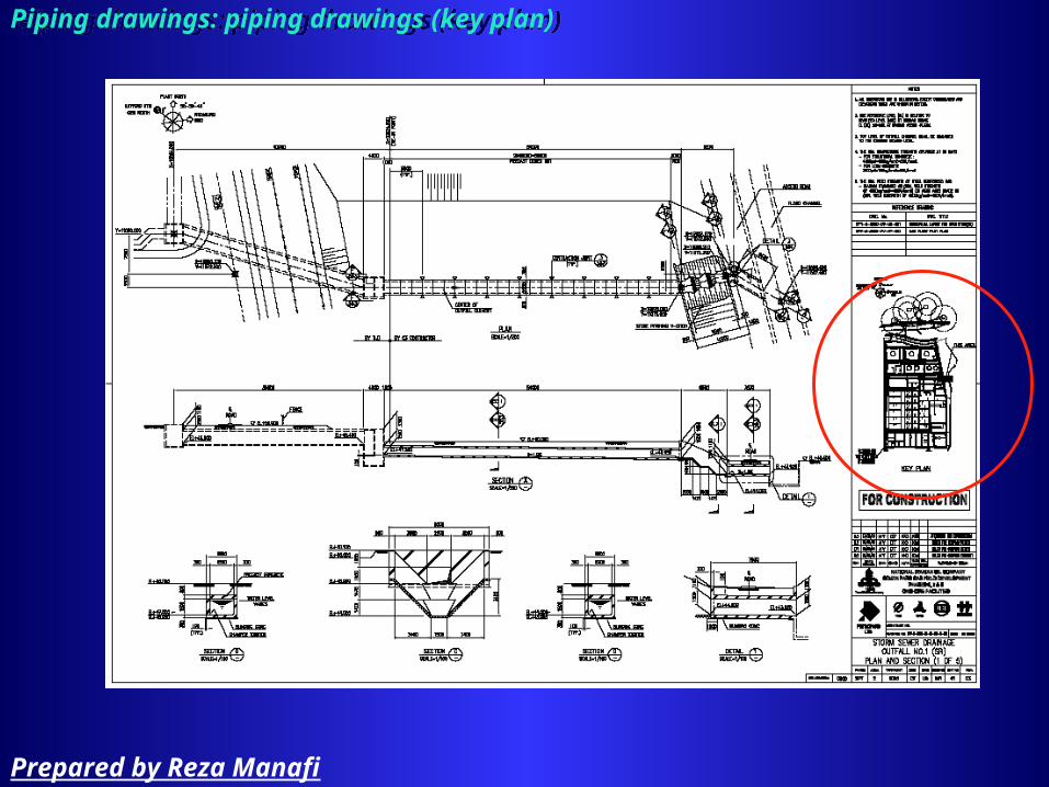
Key plan
Piping drawings: drawing component (key plan)Piping drawings: drawing component (key plan)
Prepared by Reza Manafi

reference drawing
Piping drawings: drawing component (reference drawing)Piping drawings: drawing component (reference drawing)
Prepared by Reza Manafi

legend
Piping drawings: drawing component (legend)Piping drawings: drawing component (legend)
Prepared by Reza Manafi

Important note
Piping drawings: drawing component (important note)Piping drawings: drawing component (important note)
Prepared by Reza Manafi

Graphic reference point
Piping drawings: drawing component (Graphic reference point)Piping drawings: drawing component (Graphic reference point)
Prepared by Reza Manafi

Piping drawings: drawing component (Graphic reference point)Piping drawings: drawing component (Graphic reference point)
Graphic reference point
Graphic reference point
Ex Nyy
x
True north
Plant north
Prepared by Reza Manafi

Line number shall be labeled to show the area of project, conveyed fluid, line size, piping material or specification code number and number of line
Allocate new number to branch
Piping drawings: line numberPiping drawings: line number
Prepared by Reza Manafi
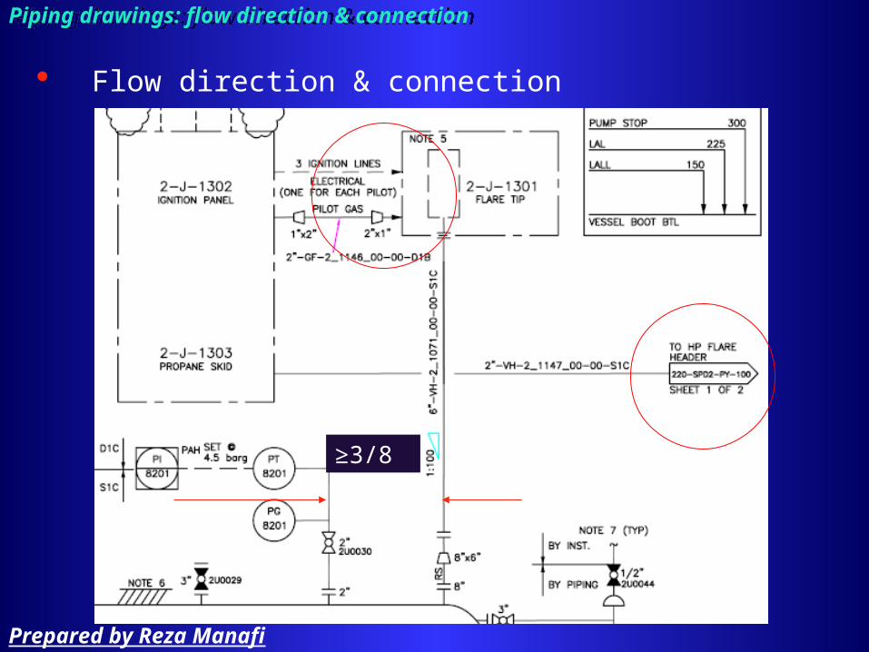
Flow direction & connection
Piping drawings: flow direction & connectionPiping drawings: flow direction & connection
≥3/8”
Prepared by Reza Manafi

Line list
Prepared by Reza Manafi
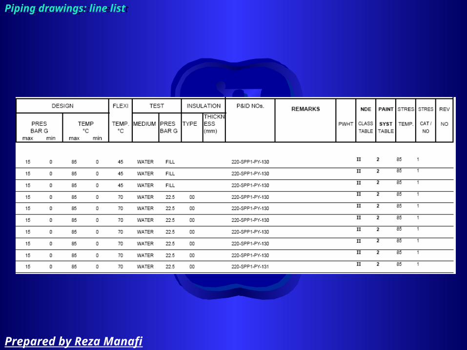
Line list (line designation sheet or table) include:
– The number of the line – Line size– Material of construction– Conveyed fluid– Pressure, temperature, flow rate– Test pressure – Insulation and jacketing– Connected line (which will usually branch)
Piping drawings: line listPiping drawings: line list
Prepared by Reza Manafi

Piping drawings: line listPiping drawings: line list
Prepared by Reza Manafi
Piping drawings: line listPiping drawings: line list
Prepared by Reza Manafi

Drawing view
Prepared by Reza Manafi
Two type of view are used for piping drawing:
– Orthographic• Plans √• Elevation
– Pictorial:
in complex piping system where orthographic view may not easily illustrate the design
• Isometric √• Oblique
Piping drawings: drawing viewPiping drawings: drawing view
Prepared by Reza Manafi

Piping drawings: drawing viewPiping drawings: drawing view
Prepared by Reza Manafi

Piping drawings: drawing viewPiping drawings: drawing view
Prepared by Reza Manafi

Piping drawing
Prepared by Reza Manafi

Piping drawing include:
– Site plan• Key plan
– Equipment layout– Piping layout (plan)– Isometric– Support drawing– …
Piping drawings: piping drawingsPiping drawings: piping drawings
Prepared by Reza Manafi
Piping drawings: piping drawings (site plan)Piping drawings: piping drawings (site plan)
Prepared by Reza Manafi
Piping drawings: piping drawings (key plan)Piping drawings: piping drawings (key plan)
Prepared by Reza Manafi

Piping drawings: piping drawings (key plan)Piping drawings: piping drawings (key plan)
Prepared by Reza Manafi

Piping drawings: piping drawings (Equipment arrangement drawing)Piping drawings: piping drawings (Equipment arrangement drawing)
Prepared by Reza Manafi

Piping drawings: piping drawings (Equipment arrangement drawing)Piping drawings: piping drawings (Equipment arrangement drawing)
Prepared by Reza Manafi
piping symbols for fittings, flanges, special items
Prepared by Reza Manafi

Piping abbreviation
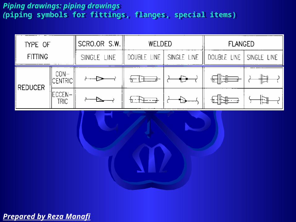
Piping drawings: piping drawings (piping symbols for fittings, flanges, special items)
Piping drawings: piping drawings (piping symbols for fittings, flanges, special items)
Prepared by Reza Manafi

Piping drawings: piping drawings (piping symbols for fittings, flanges, special items)
Piping drawings: piping drawings (piping symbols for fittings, flanges, special items)
Prepared by Reza Manafi

Piping drawings: piping drawings (piping symbols for fittings, flanges, special items)
Piping drawings: piping drawings (piping symbols for fittings, flanges, special items)
Prepared by Reza Manafi
Piping drawings: piping drawings (piping symbols for fittings, flanges, special items)
Piping drawings: piping drawings (piping symbols for fittings, flanges, special items)
Prepared by Reza Manafi

Piping drawings: piping drawings (piping symbols for fittings, flanges, special items)
Piping drawings: piping drawings (piping symbols for fittings, flanges, special items)
Prepared by Reza Manafi

Piping drawings: piping drawings (piping symbols for fittings, flanges, special items)
Piping drawings: piping drawings (piping symbols for fittings, flanges, special items)
Prepared by Reza Manafi

Piping drawings: piping drawings (piping symbols for fittings, flanges, special items)
Piping drawings: piping drawings (piping symbols for fittings, flanges, special items)
Prepared by Reza Manafi

Piping drawings: piping drawings (piping symbols for fittings, flanges, special items)
Piping drawings: piping drawings (piping symbols for fittings, flanges, special items)
Prepared by Reza Manafi
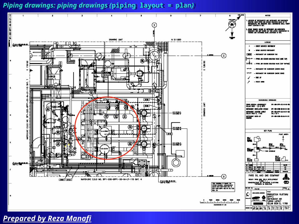
Piping drawings: piping drawings (piping layout = plan)Piping drawings: piping drawings (piping layout = plan)
Prepared by Reza Manafi

Piping drawings: piping drawings (piping layout = plan)Piping drawings: piping drawings (piping layout = plan)
Prepared by Reza Manafi
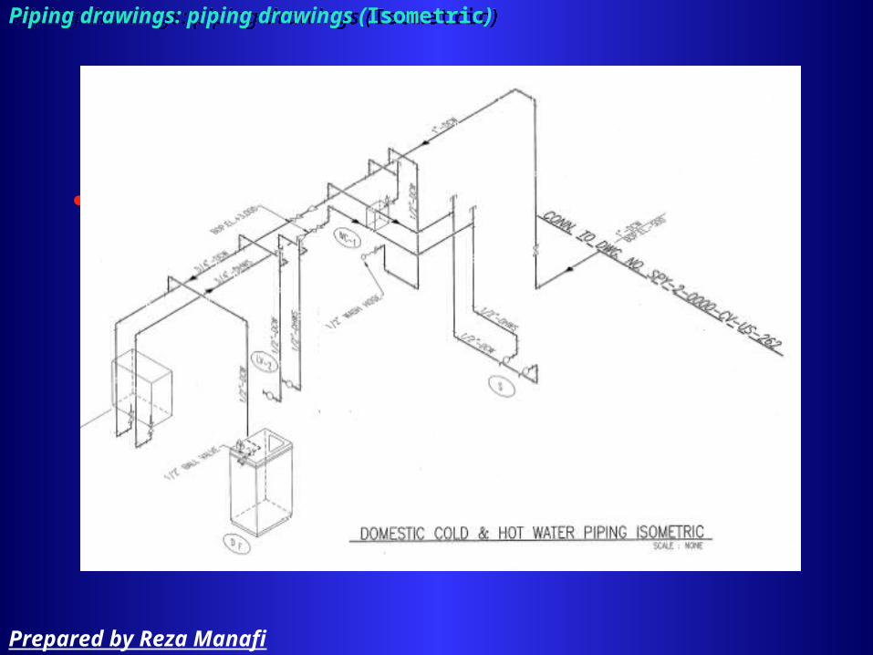
Piping drawingPiping drawing
isometric
Piping drawings: piping drawings (Isometric)Piping drawings: piping drawings (Isometric)
Prepared by Reza Manafi
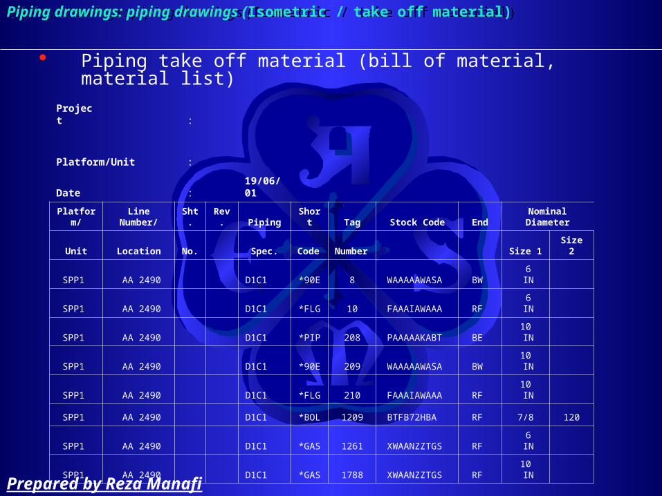
Piping take off material (bill of material, material list)
Project :
Platform/Unit :
Date : 19/06/01
Platform/ Line Number/ Sht. Rev. Piping Short Tag Stock Code End Nominal Diameter
Unit Location No. Spec. Code Number Size 1 Size 2
SPP1 AA 2490 D1C1 *90E 8 WAAAAAWASA BW 6 IN
SPP1 AA 2490 D1C1 *FLG 10 FAAAIAWAAA RF 6 IN
SPP1 AA 2490 D1C1 *PIP 208 PAAAAAKABT BE 10 IN
SPP1 AA 2490 D1C1 *90E 209 WAAAAAWASA BW 10 IN
SPP1 AA 2490 D1C1 *FLG 210 FAAAIAWAAA RF 10 IN
SPP1 AA 2490 D1C1 *BOL 1209 BTFB72HBA RF 7/8 120
SPP1 AA 2490 D1C1 *GAS 1261 XWAANZZTGS RF 6 IN
SPP1 AA 2490 D1C1 *GAS 1788 XWAANZZTGS RF 10 IN
Piping drawings: piping drawings (Isometric / take off material)Piping drawings: piping drawings (Isometric / take off material)
Prepared by Reza Manafi

Piping material take off
RatingThickness Qty. Weight Description
SCH/MM (kg/ps)
80 1 15.35 90 DEG. LR ELBOW, A234 GR.WPB SS SEAMLESS, B16.9
150 80 1 10.6 WELDING NECK FLANGE, ASTM A105N SS, B16.5.
80 4.8 95.74 SEAMLESS PIPE, API 5L GR.B SS
80 1 59.8 90 DEG. LR ELBOW, A234 GR.WPB SS SEAMLESS, B16.9
150 80 2 23.9 WELDING NECK FLANGE, ASTM A105N SS, B16.5.
12 0 STUD BOLT, A193 GR.B7, WITH 2 HEAVY HEX.NUTS, A194 GR.2H, PTFE COATED
150 1 0 FLAT GASKET, TANGED GRAPHITE/AISI 316 INSERT,ANSI B16.21 (B16.5), THK = 1.5MM
150 1 0 FLAT GASKET, TANGED GRAPHITE/AISI 316 INSERT,ANSI B16.21 (B16.5), THK = 1.5MM
Piping drawings: piping drawings (Isometric / take off material)Piping drawings: piping drawings (Isometric / take off material)
Prepared by Reza Manafi

Welding Welding
Prepared by Reza Manafi

What is Welding?
– Welding is a joining process in which metals are heated, melted and mixed to produce a joint with properties similar to those of the materials being joined.
Welding Welding
Penetration Depth
Weld Reinforcement
Heat Affected Zone (HAZ)
Weld PoolParent Metal
Weld Root
Prepared by Reza Manafi
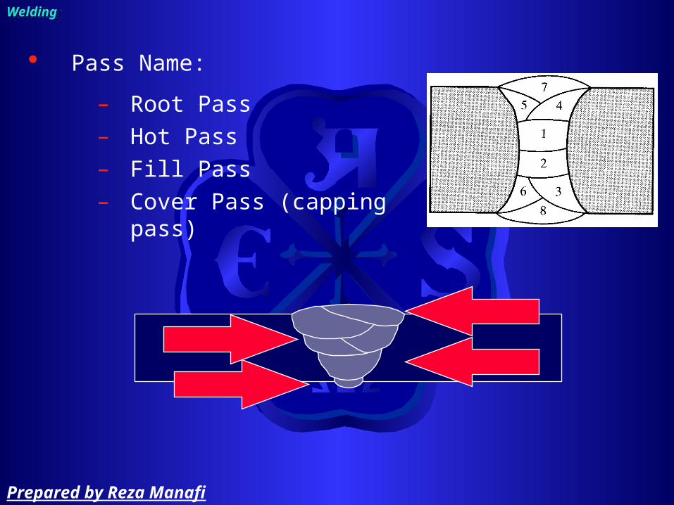
Pass Name:
– Root Pass – Hot Pass– Fill Pass– Cover Pass (capping pass)
Welding Welding
Prepared by Reza Manafi

Weld type:
– Fillet• Used when joining two pieces of metal
without preparing the surface of the metal first.
– Groove• used when preparing the metal before
welding it into place, include:– Square– Bevel– Single or double V– Single or double U– Single or double J
Welding Welding
Prepared by Reza Manafi

Fillet
– Approximately triangular– Most common weld in structural work
Welding Welding
Prepared by Reza Manafi

groove
– Square
• Penetration difficult with single; double used to ensure strength
• Sometimes root is opened and a backing bar is used
Welding Welding
Prepared by Reza Manafi

groove
– Bevel• Single bevel is widely used• Double preferred if metal thickness >3/4
Welding Welding
Prepared by Reza Manafi
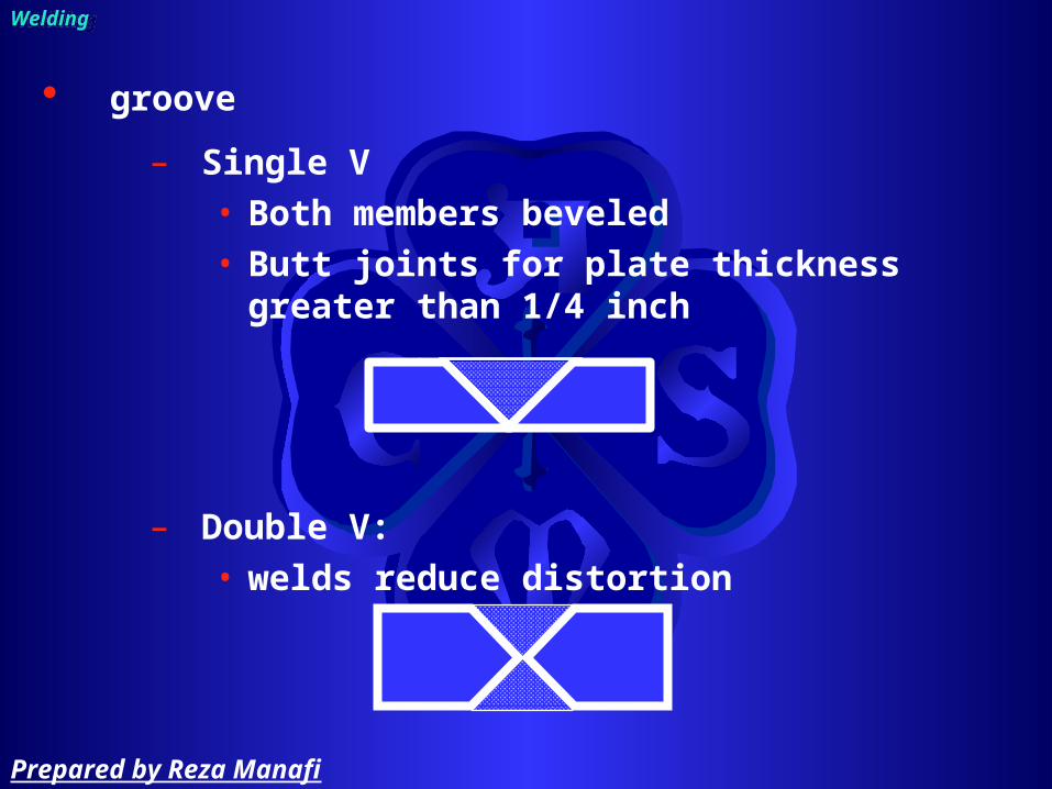
groove
– Single V• Both members beveled• Butt joints for plate thickness greater than
1/4 inch
– Double V:• welds reduce distortion
Welding Welding
Prepared by Reza Manafi

groove
– Single and double U:• Rounded base allows larger electrodes
for narrower groove angles• Machined or carbon arc gouged
preparation
Welding Welding
Prepared by Reza Manafi

groove
– Single or double J• Single well suited for butted corner and T
joints• Machined or carbon arc gouged
preparation
Welding Welding
Prepared by Reza Manafi
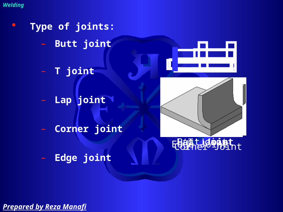
Type of joints:
– Butt joint
– T joint
– Lap joint
– Corner joint
– Edge joint
Welding Welding
Butt Joint‘T’ JointLap JointCorner JointEdge Joint
Prepared by Reza Manafi

Type of joints:
– Butt joint
Welding Welding
Prepared by Reza Manafi
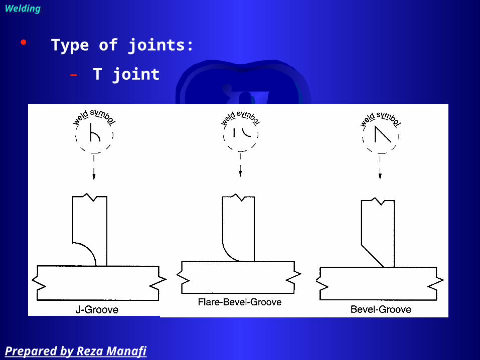
Type of joints:
– T joint
Welding Welding
Prepared by Reza Manafi
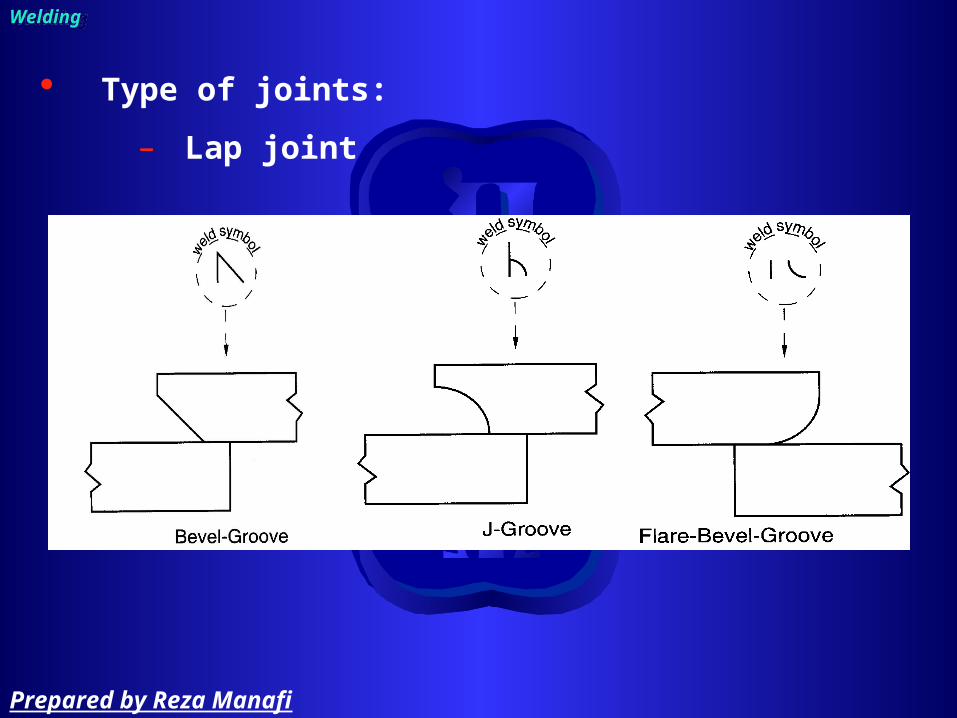
Type of joints:
– Lap joint
Welding Welding
Prepared by Reza Manafi

Type of joints:
– Corner joint
Welding Welding
Prepared by Reza Manafi

Type of joints:
– Edge joint
Welding Welding
Prepared by Reza Manafi

Pipe welding position Pipe welding position
Prepared by Reza Manafi

Position:
– Flat– Horizontal– Vertical– Overhead
Welding Welding
Prepared by Reza Manafi
Position according to standards:
– 1G– 2G– 5G– 6G
– 1F– 2F– 2FR– 4F– 5F
Welding Welding
Prepared by Reza Manafi

Position:
– 1G• Pipe rotated, Electrode is always at the top• Either a split bead or weave technique may be
used
Welding Welding
Prepared by Reza Manafi

Position:
– 2G• Pipe Axis Vertical, Weld is Horizontal, Pipe is
considered in a “fixed” position.• Always use a split bead technique• Always work from the bottom up.
Welding Welding
Prepared by Reza Manafi

Position:
– 5G– Axis of the Pipe is Horizontal, The weld in vertical.– Progression may be up or down.– A weave bead is best used.
Welding Welding
Prepared by Reza Manafi

Position:
– 6G• Pipe axis is fixed in position at a 45 degree
incline. The position includes flat, horizontal, vertical, and overhead welds.
• A split bead technique is best used.
Welding Welding
Prepared by Reza Manafi

Position:
– 1F• Pipe is rotated. The pipe axis is at a 45
degree incline. Welding is to occur at the top of the pipe.
• Split bead or weave technique may be used.
Welding Welding
Prepared by Reza Manafi

Position:
– 2F• Fixed Position• Best to use a split bead technique
Welding Welding
Prepared by Reza Manafi

Position:
– 2FR– Rotated– A split bead technique is best used.
Welding Welding
Prepared by Reza Manafi
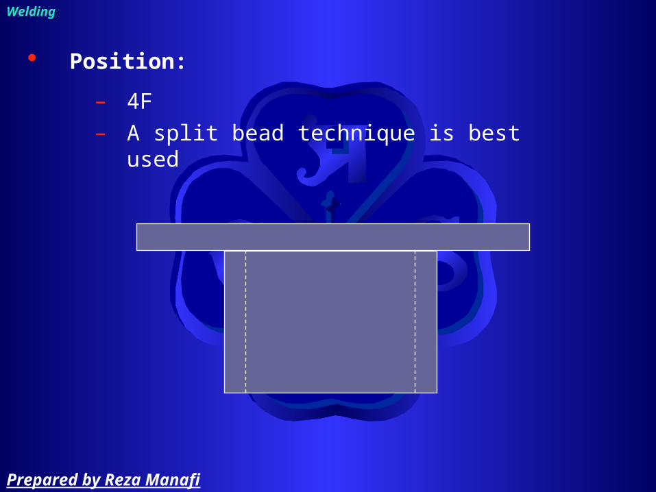
Position:
– 4F– A split bead technique is best used
Welding Welding
Prepared by Reza Manafi
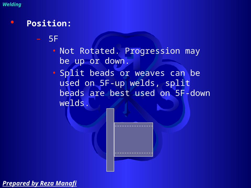
Position:
– 5F• Not Rotated. Progression may be up or
down. • Split beads or weaves can be used on
5F-up welds, split beads are best used on 5F-down welds.
Welding Welding
Prepared by Reza Manafi
Type of welding:
– Oxy-fuel gas welding
– Arc welding• SMAW• GTAW
Welding Welding
Prepared by Reza Manafi

Oxy-fuel gas weldingOxy-fuel gas welding
Welding Welding
Prepared by Reza Manafi

Basic Oxy-fuel Gas Welding Equipment
Welding Welding
Prepared by Reza Manafi

Pressure Regulators
Welding Welding
Prepared by Reza Manafi

Acetylene and oxygen cylinder
Welding Welding
Prepared by Reza Manafi

Carburizing, Neutral, and Oxidizing Flames
Welding Welding
Prepared by Reza Manafi

Applications of Oxy-fuel Gas Welding
– Recommended for material up to 3.2mm (1/8in) Most steels, rolled, wrought or cast
– Root opening• Up to 4.8mm (3/16in) square butt O.K.• Up to 6.8mm (1/4in) root opening and filler• Above 6.8mm parts must be beveled
Welding Welding
Prepared by Reza Manafi
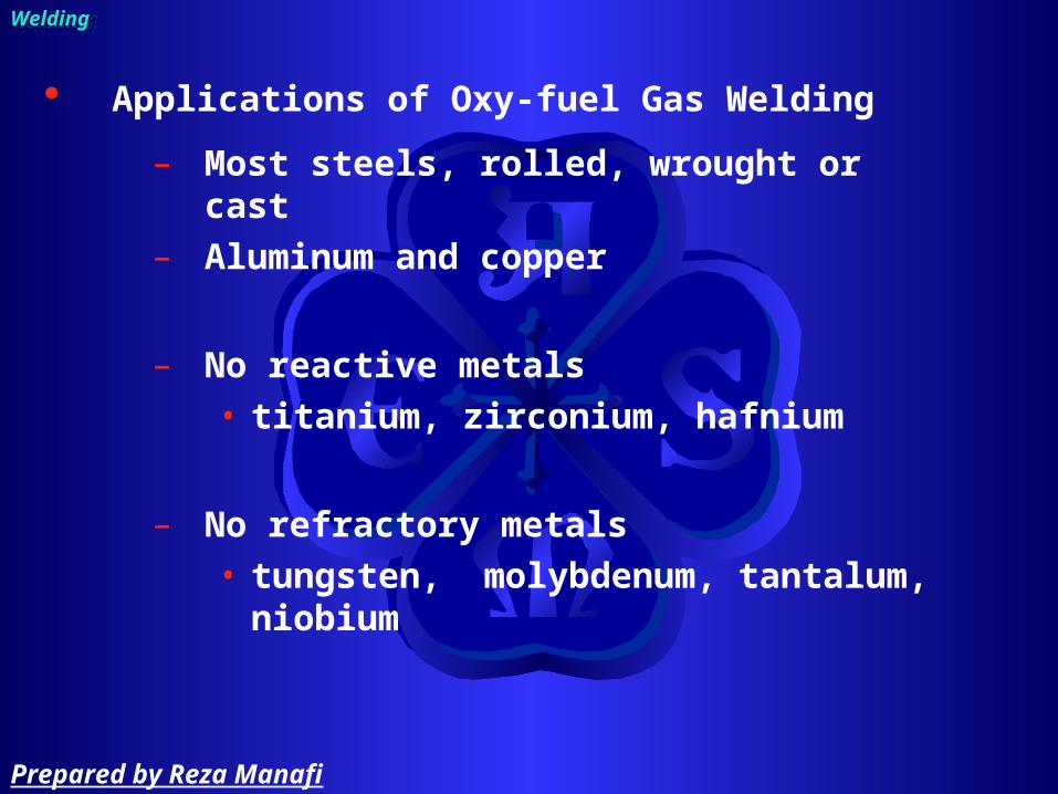
Applications of Oxy-fuel Gas Welding
– Most steels, rolled, wrought or cast– Aluminum and copper
– No reactive metals• titanium, zirconium, hafnium
– No refractory metals• tungsten, molybdenum, tantalum,
niobium
Welding Welding
Prepared by Reza Manafi

Advantages of Oxy-fuel Gas Welding
– Very portable– Low cost– Gentle flame
Disadvantages of Oxy-fuel Gas Weld.
– Poor air protection– Low heat input– Safety issues
Welding Welding
Prepared by Reza Manafi
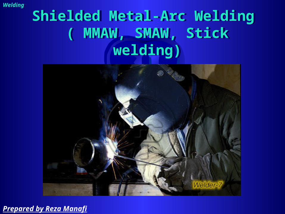
Shielded Metal-Arc Welding ( MMAW, SMAW, Stick welding)
Shielded Metal-Arc Welding ( MMAW, SMAW, Stick welding)
Welding Welding
Prepared by Reza Manafi

WorkLead
+
-
Electrodelead
Power SourceDCEP Shown
Base material
ElectrodeCoating
Core wire
Weld pool
Slag
Weld metal
Welding Welding
SMAW process:
Prepared by Reza Manafi

Welding Welding
electrodeelectrode
Prepared by Reza Manafi

E xx y z – n HmR
positions (y)1=all positions2=flat + horizontal4=vertical down
Tensile strength41 = 410 MPa min48 = 480 MPa min
Flux type (z)0, 1 = cellulosic2, 3, 4 = rutile5, 6, 8 = low hydrogen7 = iron powder + iron oxide
Impact properties (n)0 = 47J at 0°C2 = 47J at -20°C3 = 47J at -30°C4 = 47J at -40°C
Hydrogen level (HmR)H5 = 5 ml / 100g of WMR = low moisture
Welding Welding
Electrode numbering:
Prepared by Reza Manafi
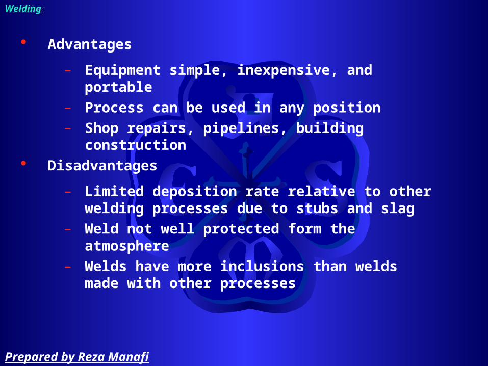
Advantages
– Equipment simple, inexpensive, and portable– Process can be used in any position– Shop repairs, pipelines, building construction
Disadvantages
– Limited deposition rate relative to other welding processes due to stubs and slag
– Weld not well protected form the atmosphere– Welds have more inclusions than welds made
with other processes
Welding Welding
Prepared by Reza Manafi

SMAW usually restricted to metals between 3 to 19mm (1/8 to 3/4 in) thick.
Typical pass 3mm (1/8 in) thick.
Welding Welding
Prepared by Reza Manafi

Gas Tungsten Arc WeldingGas Tungsten Arc Welding
Welding Welding
Prepared by Reza Manafi

Ceramic shroud
Torch
Gas lens(optional)
Inertgas
Powersource
Torch lead (-)
Work lead (+)
FillerArc
Weld metal
Weld pool
Collet
Tungsten electrode
Welding Welding
GTAW process:
Prepared by Reza Manafi

Gas Tungsten Arc Welding
Welding Welding
SMAW process:
Prepared by Reza Manafi

Welding Welding
Shielding gases:
– Pure argon, Argon-helium, Argon-2% hydrogen
– Torch gas must not contain oxygen or CO2
Backing (or purge) gas
– Used for all single-sided welds except in carbon steel
Supplementary shielding
– Reactive metals: Ti, etc
Prepared by Reza Manafi

Welding Welding
TIG Process features :
– can also be used to weld dissimilar metals (but not very well)
– Slower and more costly than consumable welding
– Independently added filler– Used for root, pass runs in pipe or thin
sheet– High quality, Clean process, no slag– Low oxygen and nitrogen weld metal– Defect free, excellent profile even for single
sided welds
Prepared by Reza Manafi

Welding Welding
Filler metals:
– Filler wire or rod of matching composition• C-Mn & low alloy steel• Stainless Steel• Al, Mg, Ti• Cu & Ni
– Consumable inserts - filler replaced in joint
Prepared by Reza Manafi

Welding Symbols
Prepared by Reza Manafi

The welding symbols devised by the AWS has 8 elements
– Reference line– Arrow– Basic weld symbols– Dimensions and other data– Supplementary symbols– Finish symbols– Tail– Specification or others reference
Welding symbols:Welding symbols:
Prepared by Reza Manafi
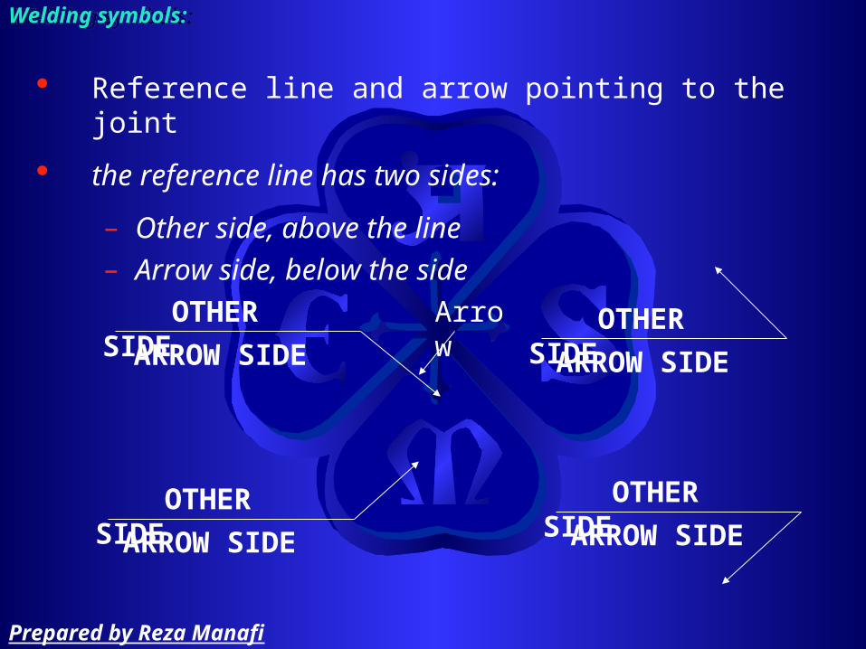
Reference line and arrow pointing to the joint
the reference line has two sides:
– Other side, above the line– Arrow side, below the side
Welding symbols:Welding symbols:
ARROW SIDE
OTHER SIDE Arrow
ARROW SIDE
OTHER SIDE
ARROW SIDE
OTHER SIDE
ARROW SIDE
OTHER SIDE
Prepared by Reza Manafi
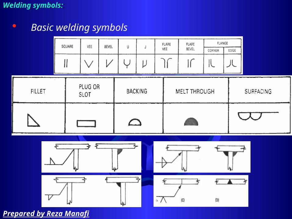
Basic welding symbols
Welding symbols:Welding symbols:
Prepared by Reza Manafi

If a bevel groove is required the use broken arrow
Welding symbols:Welding symbols:
Prepared by Reza Manafi

Dimensions and other data
Welding symbols:Welding symbols:
Prepared by Reza Manafi

Dimensions and other data
Welding symbols:Welding symbols:
Prepared by Reza Manafi

Dimensions and other data
Welding symbols:Welding symbols:
Prepared by Reza Manafi

Welding symbols:Welding symbols:
Supplementary symbols
Prepared by Reza Manafi
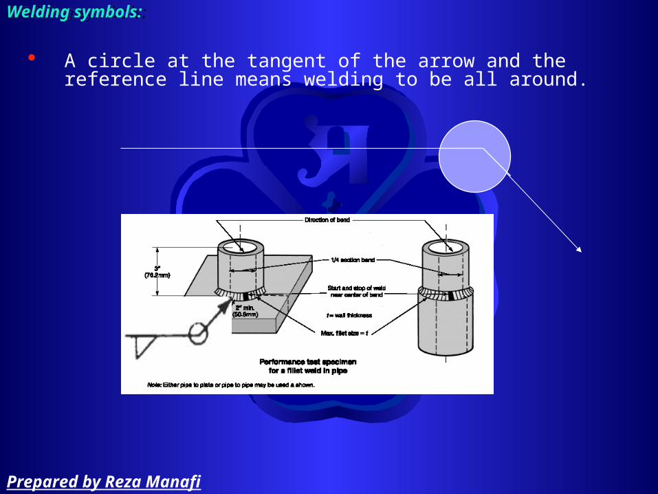
Welding symbols:Welding symbols:
A circle at the tangent of the arrow and the reference line means welding to be all around.
Prepared by Reza Manafi

Welding symbols:Welding symbols:
A flag at the tangent of the reference line and arrow means Field Weld.
Prepared by Reza Manafi
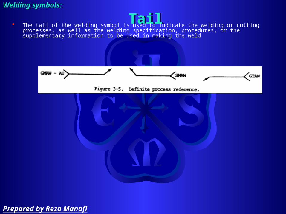
TailTailWelding symbols:Welding symbols:
The tail of the welding symbol is used to indicate the welding or cutting processes, as well as the welding specification, procedures, or the supplementary information to be used in making the weld
Prepared by Reza Manafi

Welding symbols:Welding symbols:
Prepared by Reza Manafi

Arrangement
Prepared by Reza Manafi

Design flexible arrangement for piping to reduce
– thermal stress (induce stress in piping, support and attachment equipment) – settlement strain (foundation of large tanks and heavy equipment may settle or tilt slightly in course of time)
Arrangement: Flexibility Arrangement: Flexibility
Prepared by Reza Manafi

Arrangement: Flexibility Arrangement: Flexibility
Prepared by Reza Manafi

Avoid cold spring of pipe
– Cold spring used in to manner • To reduce stress• To avoid an interference
Arrangement: Flexibility Arrangement: Flexibility
Prepared by Reza Manafi

Flexible pipe connection should have a length of 6 to 10 NPS
Arrangement: Flexibility Arrangement: Flexibility
Prepared by Reza Manafi

Take gas and vapor branch lines from tops of header where it is necessary to reduce the chance of drawing off condensate or sediment which may damage rotating equipment
Arrangement:Arrangement:
Prepared by Reza Manafi
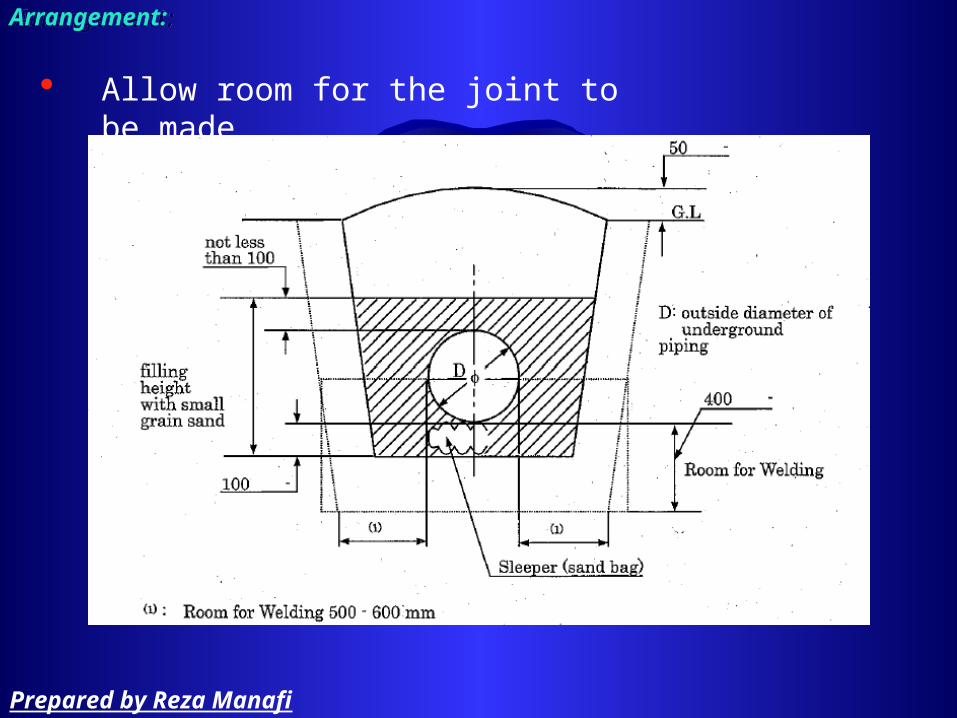
Allow room for the joint to be made
Arrangement:Arrangement:
Prepared by Reza Manafi

Establish sufficient headroom for ductwork, electrical run
Consider vertical clearance (don’t route piping) over pump compressor to permit removal for servicing (maintenance), consider headroom for mobile crane
Arrangement:Arrangement:
Prepared by Reza Manafi

Centrifugal Pump arrangement:
– Suction: eccentric reducer are used in 2½” line and larger
Arrangement:Arrangement:
Prepared by Reza Manafi

Centrifugal Pump arrangement:
– Suction (socket weld)
Arrangement:Arrangement:
Prepared by Reza Manafi

Centrifugal Pump arrangement:
– Suction arrangement
Arrangement:Arrangement:
Prepared by Reza Manafi

Don’t use globe valves at suction and discharge for isolating pump
Route suction line as directly as possible Don’t route piping over the pump, as this interferes with maintenance
If pump positioned close to supply tanks and are on separate foundations, avoid rigid piping arrangement, for settle of tank in course of time
Locate the pump as closely as practicable to source of liquid to be pumped from storage tank
Arrangement:Arrangement:
Prepared by Reza Manafi

Centrifugal Pump arrangement:
– Discharge: Concentric reducers are used in 2” line and smaller
Arrangement:Arrangement:
Prepared by Reza Manafi

Centrifugal Pump arrangement:
– Discharge (socket)
Arrangement:Arrangement:
Prepared by Reza Manafi

Centrifugal Pump arrangement:
– Discharge (manifold)
Arrangement:Arrangement:
Prepared by Reza Manafi

Provide ¾” to ½” drain between ball valve and check valve at discharge of pump to drain
Drain can be provided on above disk of check valve
Arrangement:Arrangement:
Prepared by Reza Manafi
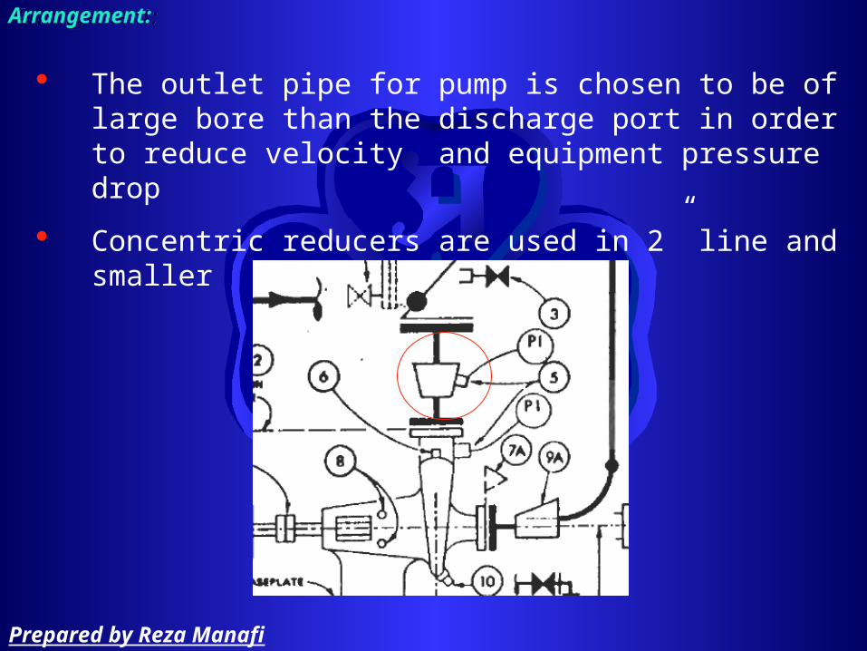
The outlet pipe for pump is chosen to be of large bore than the discharge port in order to reduce velocity and equipment pressure drop
Concentric reducers are used in 2” line and smaller
Arrangement:Arrangement:
Prepared by Reza Manafi

Each pump is usually provided with a drain hub 4” to 6” positioned about 9” in front of the pump
Arrangement:Arrangement:
Prepared by Reza Manafi

Positive displacement Pump arrangement:
– Install PRV at discharge line befor isolating valve– pump PDP don’t change velocity so, reducer at discharge and suction not used
Arrangement:Arrangement:
Prepared by Reza Manafi
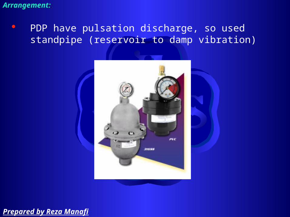
PDP have pulsation discharge, so used standpipe (reservoir to damp vibration)
Arrangement:Arrangement:
Prepared by Reza Manafi

Compressor arrangement:
Arrangement:Arrangement:
Prepared by Reza Manafi

Compressor arrangement
– suction
Arrangement:Arrangement:
Prepared by Reza Manafi

Compressor arrangement
– discharge
Arrangement:Arrangement:
Prepared by Reza Manafi

Turbine piping arrangement
Arrangement:Arrangement:
Prepared by Reza Manafi

Piping may have thru concrete floor as walls, inform the civil and architectural to avoid cutting exciting reinforcement
Don’t run piping under foundation
If there is no possibility of future road or site development, lay piping such as
– Line to outside storage – Loading and receiving facilitiesAt grade on pipe sleeper
Avoiding burying steam line that pocket, due the difficulty to collecting condensate
Burying line (water, gas, drain) bellow the frost line to avoid freezing water and solutions, save the expense of tracing long horizontal parts of the line
Arrangement:Arrangement:
Prepared by Reza Manafi

Vent all high point and drain all low point on lines, place vent and drain valve to permit easily drained or purged during shutdown period (important for reducing cost of winterizing)
Avoid pocketing lines. Arrange piping lines to drain back into equipment or into lines that can to be drained
Run piping beneath of platforms, rather than over them.
If need removing equipment, cleaning line provide
– Union– Flanged– Removable spool– Cross instead elbows to permit removing solid
Arrangement:Arrangement:
Prepared by Reza Manafi

Don’t obstruct access ways (doorways, escape road, …)
Consider vertical clearance (don’t route piping) over pump to permit removal for servicing (maintenance), consider headroom for mobile crane
Arrangement:Arrangement:
Prepared by Reza Manafi
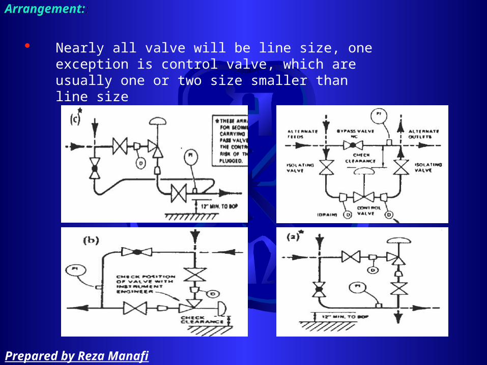
Nearly all valve will be line size, one exception is control valve, which are usually one or two size smaller than line size
Arrangement:Arrangement:
Prepared by Reza Manafi
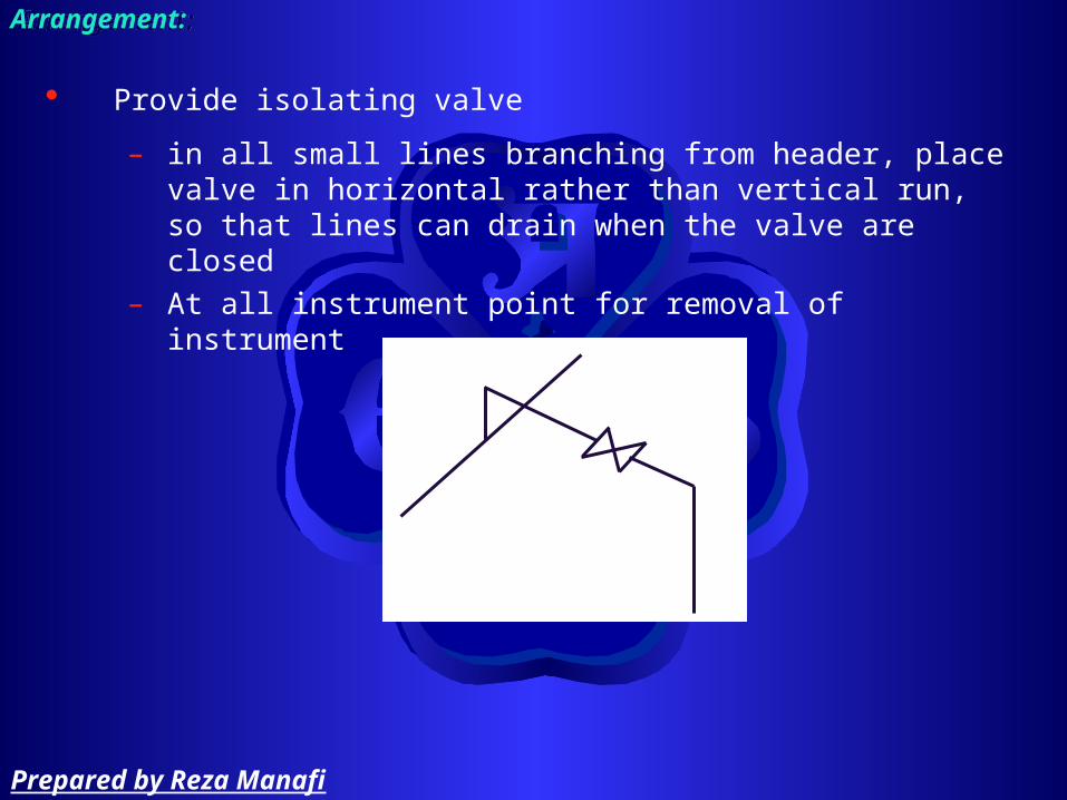
Provide isolating valve
– in all small lines branching from header, place valve in horizontal rather than vertical run, so that lines can drain when the valve are closed
– At all instrument point for removal of instrument
Arrangement:Arrangement:
Prepared by Reza Manafi

Utility station
– Steam line NPS > ¾”, use globe valve– Air and water > 1” , use gate valve– Terminate with house connection
3 ½”
Arrangement:Arrangement:
Prepared by Reza Manafi

Arrange valve so that support will not be on removable spools
In critical application, use two pressure relive valve with interlock
Arrangement:Arrangement:
Prepared by Reza Manafi

A relive valve that discharged to into a header should be placed higher than the header in order to drain into it
Arrangement:Arrangement:
Prepared by Reza Manafi

Required space between pipes
Arrangement:Arrangement:
Prepared by Reza Manafi

Pipe WorkPipe Work

Material work:
– Fabricate, test, certificate– Test (spectrograph), marking
Storing
– SS shall be separated from other steels and without any contact to zinc material
Pipe workPipe work
Prepared by Reza Manafi

Person who are engaged for
– Tack welding
– Welding
Shall be qualified according to ASME SEC. IX
– Pipe fitting
– Assembling
– Erection
– Control weld temperature
fully trained and have certificate (license, pass) of employer
Pipe workPipe work
Prepared by Reza Manafi

Cutting method:
– Shear– Milling– Planer– Flame cutting– Flame gouging– Arc gouging
Pipe workPipe work
Prepared by Reza Manafi

Cutting:
– In the case of thermal cutting• Cutting surface shall be ground to remove any edge
and roughness (dross, scale, .. At HAZ) and to be made flush and smooth
• Cutting slag stuck to the inside of the pipe shall be completely removed
• After thermal cutting– Machining for C.S, SS not require– for other material required (3 mm of HAZ)
– In the abrasive disk case• Abrasive disk for SS shall not be used for C.S or
vise verse– Plasma jet cutting may be applied for SS, etc
Pipe workPipe work
Prepared by Reza Manafi
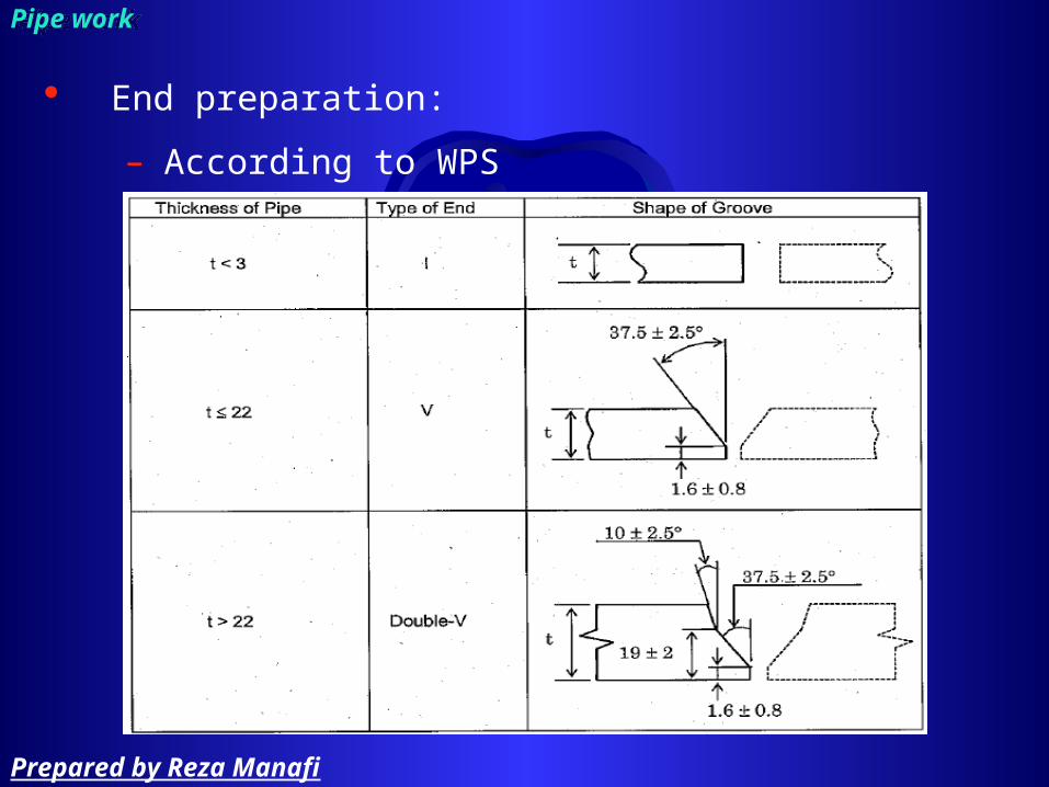
End preparation:
– According to WPS
Pipe workPipe work
Prepared by Reza Manafi

Trimming:
– When having unequal wall thickness (the difference is more than 3 mm for outer surface and/or 1.5 mm in inner surface
Pipe workPipe work
Prepared by Reza Manafi

Trimming for making branch connection
– Shall be inserted at least as far as the inside surface of pipe run
Pipe workPipe work
Prepared by Reza Manafi

Alignment:
– When a pipe having a longitudinal seam is used in a horizontal line, the pipe shall be laid so that the longitudinal weld seam is not on bottom or top of the pipe
Pipe workPipe work
Prepared by Reza Manafi

Pipe workPipe work
Prepared by Reza Manafi
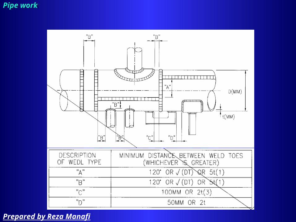
Pipe workPipe work
Prepared by Reza Manafi

To measure root opening use taper gauge
Pipe workPipe work
Prepared by Reza Manafi
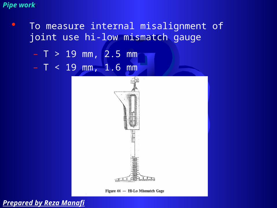
To measure internal misalignment of joint use hi-low mismatch gauge
– T > 19 mm, 2.5 mm– T < 19 mm, 1.6 mm
Pipe workPipe work
Prepared by Reza Manafi
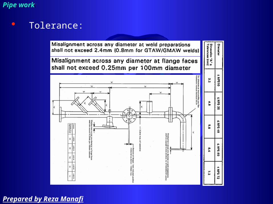
Tolerance:
Pipe workPipe work
Prepared by Reza Manafi

cleaning:
– The bevel shall be fully clean so that there is no rust, oil, grease, … (50 mm from bevel edge)
• Solvent:– Non-injurious to the material– Halide free
– Material of wire brush shall be properly selected for working CS and SS respectively
• Iron free• Grinding wheel (or disk) shall be organic resin bond
Pipe workPipe work
Prepared by Reza Manafi

Preheating:
– Shall be performed by propane prior to tack welding and welding
– Valve shall be open during preheating, …– Where the ambient temperature is below 5C, preheating
temperature = 40 (except Cu-Ni, Ti)
Pipe workPipe work
Prepared by Reza Manafi
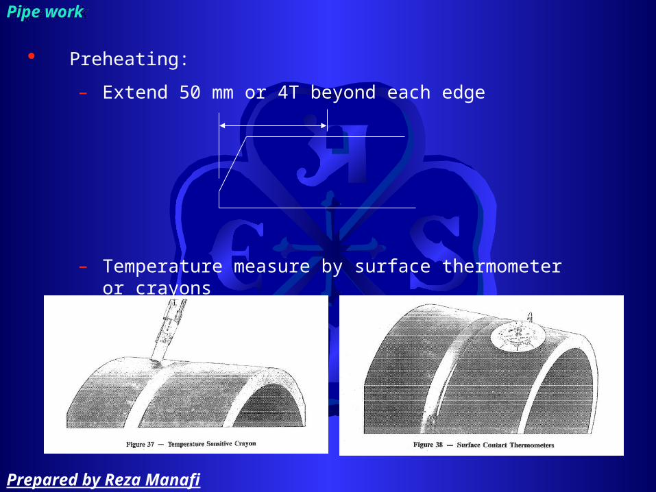
Preheating:
– Extend 50 mm or 4T beyond each edge
– Temperature measure by surface thermometer or crayons
Pipe workPipe work
Prepared by Reza Manafi
Preheating:
– Preheat temperature shall be measured based on 2 minutes per 25 mm thickness
Pipe workPipe work
Prepared by Reza Manafi

Tack weld
– Use internal or external clamps before tack weld
Pipe workPipe work
Prepared by Reza Manafi

Pipe workPipe work
Prepared by Reza Manafi

Tack weld
– Ensure the contact surface of the clamps are made of same base metal
– Before welding of the root, both ends of the root tack weld bead shall be prepared with a grinder as shown in the following illustration
– Type of tack weld• Root • Bridge (Bridge tack shall never be hammered,
removed by grinding or gas cutting)
Pipe workPipe work
Prepared by Reza Manafi

Welding:
– WPS, PQR shall be approved– Welder shall be qualified according to ASME SEC. IX– All welding processes shall be protected from adverse
weather (use shelter)– All welding equipment shall be calibrated– When preheat is applied, welding shall not be interrupted
or stopped until 30% of the final weld has been completed– Bolts hole:
• symmetrically from a vertical center line• Symmetrically from plant north
Pipe workPipe work
Prepared by Reza Manafi

Welding:
– Consumable:• Consumable manufacture shall be approved by third party• Shall be close matching with base metal• Control the storage, handling, conditioning• Electrode:
– Low hydrogen electrode stored in oven and don’t re-dried more than twice
Pipe workPipe work
Prepared by Reza Manafi

Welding:
– Consumable:• Purge gas, shielding gas:
– Check Mixture tolerance, Purity, Dew point– moisture < 10 PPM– Nitrogen not used for SS– Before tack weld and root pass welding monitoring the
oxygen content < 5000 PPM– Use purge gas for
» Thin wall tubing or piping T < 5.5 mm– Root pass without backing, single sided for all weld metal
Pipe workPipe work
Prepared by Reza Manafi

Use following fitting format:
Pipe workPipe work
Prepared by Reza Manafi

Use following fitting format:
– Perform at least 2 layer weld and end point of weld at each layer shall change
Pipe workPipe work
Prepared by Reza Manafi
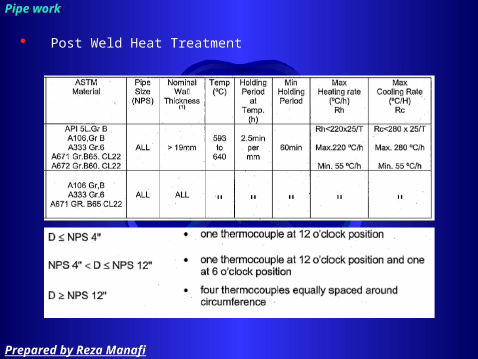
Post Weld Heat Treatment
Pipe workPipe work
Prepared by Reza Manafi

Weld Test include:
– Tensile– Bending– Impacting– Hardness
Pipe workPipe work
Prepared by Reza Manafi

Material is sectioned and edges rounded of to prevent cracking. Punch marks are made to see elongation.
Pipe work: TensilePipe work: Tensile
Prepared by Reza Manafi

Pipe work: TensilePipe work: Tensile
Prepared by Reza Manafi

Shows physical condition of the weld and Determine welds efficiency
– Tensile strength– Ductility– Fusion and penetration
Pipe work: Bend testPipe work: Bend test
Prepared by Reza Manafi

Bend through 180O
the specimen should be a minimum of 30mm wide
The fulcrums diameter is 3x thickness of the plate
The bottom rollers have a distance of the diameter of the former + 2.2 times the thickness of the plate
Upper and lower surfaces ground or filed flat and edges rounded off.
the tests should be one against the root -another against the face ,and in some cases a side bend.
Pipe work: Bend testPipe work: Bend test
Prepared by Reza Manafi

Pipe work: Bend testPipe work: Bend test
Prepared by Reza Manafi

Pipe work: Bend test: face bendPipe work: Bend test: face bend
Prepared by Reza Manafi

CHARPY AND IZOD:
– Gives the toughness and shock loading of the material and weld at varying temperatures with a notch such as under cut
– The measurement is the energy required to break a specimen with a given notch
– 2mm depth at a 45obevel or a “U” notch.
Pipe work: ImpactPipe work: Impact
Prepared by Reza Manafi
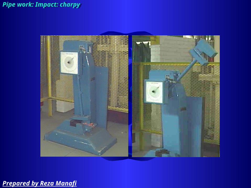
Pipe work: Impact: charpyPipe work: Impact: charpy
Prepared by Reza Manafi

Pipe work: Impact: charpyPipe work: Impact: charpy
Prepared by Reza Manafi

Pipe work: Impact: IzodPipe work: Impact: Izod
Prepared by Reza Manafi

This gives the metals ability to show resistance to indentation which show it’s resistance to wear and abrasion.
Pipe work: Hardness testsPipe work: Hardness tests
Prepared by Reza Manafi

DesignDesign
Prepared by Reza Manafi

ASME B31.3 provides requirements for:
– Design– Materials– Fabrication– Erection– Inspection– Testing
process plants including
– Petroleum refineries– Chemical plants– Pharmaceutical plants– Textile plants– Paper plants– Semiconductor– plants– Cryogenic plants
ASME B31.3 ASME B31.3
Prepared by Reza Manafi

ASME B31.3 applied to piping and piping components of all fluid services:
– Raw, intermediate, and finished chemicals– Petroleum products– Gas, steam, air, and water– Fluidized solids– Refrigerants– Cryogenic fluids
ASME B31.3: Scope of ASME B31.3ASME B31.3: Scope of ASME B31.3
Prepared by Reza Manafi
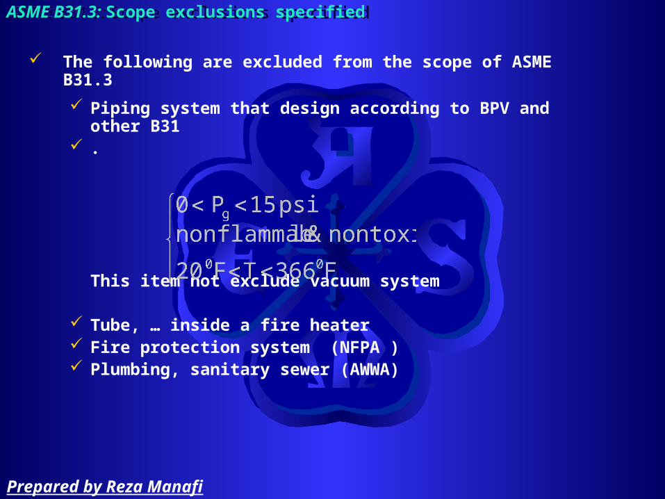
The following are excluded from the scope of ASME B31.3
Piping system that design according to BPV and other B31
.
This item not exclude vacuum system
Tube, … inside a fire heater Fire protection system (NFPA ) Plumbing, sanitary sewer (AWWA)
ASME B31.3: Scope exclusions specifiedASME B31.3: Scope exclusions specified
Prepared by Reza Manafi

The factors that affect piping material selection are:
StrengthYield & Tensile strengthCreep strengthFatigue strength
Corrosion resistance Material fracture toughness Fabricability Availability & cost
ASME B31.3: MaterialASME B31.3: Material
Prepared by Reza Manafi
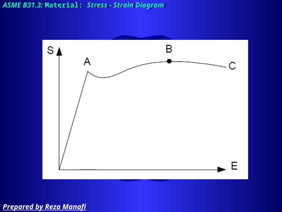
ASME B31.3: Material: Stress - Strain DiagramASME B31.3: Material: Stress - Strain Diagram
Prepared by Reza Manafi

ASME B31.3: Material: Variation of strength with temperatureASME B31.3: Material: Variation of strength with temperature
Prepared by Reza Manafi

ASME B31.3: Material: Variation of strength with temperatureASME B31.3: Material: Variation of strength with temperature
Prepared by Reza Manafi

ASME B31.3: Material: Variation of strength with temperatureASME B31.3: Material: Variation of strength with temperature
Prepared by Reza Manafi

Below about 750°F for a given stress, the strain in most materials remains constant with time. Above this temperature, even with constant stress, the strain in the material will increase with time. This behavior is known as creep.
ASME B31.3: Material: creepASME B31.3: Material: creep
Prepared by Reza Manafi

The type of fatigue are:
– Static:
specimen breaks under a load that it has previously withstood for a length of time. Examples of static fatigue are: creep fracture and stress corrosion cracking.
– Cyclic:
specimen breaks during a load cycle that it has previously withstood several times.
ASME B31.3: Material: fatigueASME B31.3: Material: fatigue
Prepared by Reza Manafi

Corrosion of materials involves deterioration of the metal by chemical or electrochemical attack and include:
– General or Uniform Corrosion: Characterized by uniform metal loss over entire surface of material. May be combined with erosion if material is exposed to high-velocity fluids, or moving fluids that contain abrasive materials.
– Pitting Corrosion: Form of localized metal loss randomly located on material surface. Occurs most often in stagnant areas or areas of low-flow velocity.
ASME B31.3: Material: Corrosion resistanceASME B31.3: Material: Corrosion resistance
Prepared by Reza Manafi

– Galvanic Corrosion:Occurs when two dissimilar metals contact each other in corrosive electrolytic environment. The anodic metal develops deep pits or grooves as a current flows from it to the cathodic metal.
ASME B31.3: Material: Corrosion resistanceASME B31.3: Material: Corrosion resistance
– Crevice Corrosion: Localized corrosion similar to pitting. Occurs at places such as gaskets, lap joints, and bolts, where a crevice can exist.
Prepared by Reza Manafi

– Concentration Cell Corrosion:
Occurs when different concentration of either corrosive fluid or dissolved oxygen contacts areas of same metal. Usually associated with stagnant fluid.
– Graphitic Corrosion:
Occurs in cast iron exposed to salt water or weak acids. Reduces iron in the cast iron and leaves the graphite in place. Result is extremely soft material with no metal loss.
ASME B31.3: Material: Corrosion resistanceASME B31.3: Material: Corrosion resistance
Prepared by Reza Manafi

It is the amount of energy necessary to initiate and propagate a crack at a given temperature.
– The addition of manganese or nickel improves fracture toughness.
– Mostly of concern for carbon steels– Generally decreases as temperature decreases– Factors affecting fracture toughness include:
• Chemical composition or alloying elements• Heat treatment• Grain size
– The impact energy required to fracture a material sample at a given temperature can be measured by standard Charpy V-notch tests.
ASME B31.3: Material: Material fracture toughnessASME B31.3: Material: Material fracture toughness
Prepared by Reza Manafi

ASME B31.3: Material: Material fracture toughnessASME B31.3: Material: Material fracture toughness
Prepared by Reza Manafi

ASME B31.3: Material: CostASME B31.3: Material: Cost
Prepared by Reza Manafi

FAILURE BY GERNRAL YIELDING: Failure is due to excessive plastic deformation.
– Yielding at Sub Elevated temperature: Body undergoes plastic deformation under slip action of grains.
– Yielding at Elevated temperature: After slippage, material re-crystallizes and hence yielding continues without increasing load. This phenomenon is known as creep.
FAILURE BY FRACTURE: Body fails without undergoing yielding.
– Brittle fracture: Occurs in brittle materials.
– Fatigue: Due to cyclic loading initially a small crack is developed which grows after each cycle and results in sudden failure.
ASME B31.3: Material: Modes of failuresASME B31.3: Material: Modes of failures
Prepared by Reza Manafi

ASME B31.3: Material: Modes of failures: Ductile DeformationASME B31.3: Material: Modes of failures: Ductile Deformation
Prepared by Reza Manafi

ASME B31.3: Material: Modes of failures: Brittle FractureASME B31.3: Material: Modes of failures: Brittle Fracture
Prepared by Reza Manafi

Category D
Category M
High Pressure
Normal
ASME B31.3: B31.3 Fluid Service DefinitionsASME B31.3: B31.3 Fluid Service Definitions
Prepared by Reza Manafi

Category D:
– The fluid handled is nonflammable, nontoxic and not damaging to human tissue. The design pressure does not exceed 150 psig (1035 kPa). The design temperature is greater than -20°F (-29°C) and does not exceed 366 °F (186°C).
– Often characterized as “utility”
ASME B31.3: B31.3 Fluid Service DefinitionsASME B31.3: B31.3 Fluid Service Definitions
Prepared by Reza Manafi

Category M:
– A fluid service in which the potential for personnel exposure is judged to be significant and in which a single exposure to a very small quantity of a toxic fluid, caused by leakage, can produce serious irreversible harm to persons upon breathing or on bodily contact, even when prompt restorative measures are taken.
– Often characterized as “lethal”
ASME B31.3: B31.3 Fluid Service DefinitionsASME B31.3: B31.3 Fluid Service Definitions
Prepared by Reza Manafi

High Pressure:
– A service for which the owner specifies the use of Chapter IX [of B31.3] for piping design and construction… considered to be in excess of Class 2500 (PN 420). Characterized as “high pressure”
Normal: Everything else.
– Often characterized as “process”
ASME B31.3: B31.3 Fluid Service DefinitionsASME B31.3: B31.3 Fluid Service Definitions
Prepared by Reza Manafi

Normal operating conditions:
Are those expected to occur during normal operation, excluding failure of any operating device, operator error, and the occasional, short-term variations stated in the applicable code.
Design conditions:
Are those which govern the design and selection of piping components, and are based on the most severe conditions expected to occur in service.
ASME B31.3: B31.3 DefinitionsASME B31.3: B31.3 Definitions
Prepared by Reza Manafi

Loading classification
– Primary loads: These can be divided into two categories based on the duration of loading.
• Sustained loads: These loads are expected to be present through out the plant operation. e.g. – internal & external pressure– weight of system (piping material and operating
pressure).
• Occasional loads: These loads are present at infrequent intervals during plant operation. e.g.– Wind, ice and snow load – seismic load– Dynamic load (pressure surge, water hammer, energy
release by pressure relief valve, …– Hydrostatic leak test load– Wheel load (traffic load)
ASME B31.3: B31.3 DefinitionsASME B31.3: B31.3 Definitions
Prepared by Reza Manafi

– Expansion loads: These are loads due to displacements of piping. e.g.
• thermal expansion:– are created when the free expansion and
contraction of the piping is prevented at its end points by connected equipment, or prevented at intermediate points by supports and/or restraints that are installed. pipe thermal loads can be from the thermal expansion of equipment at pipe-to-equipment nozzle attachment points, causing displacements in the piping system.
• seismic anchor movements• building settlement.
ASME B31.3: B31.3 DefinitionsASME B31.3: B31.3 Definitions
Prepared by Reza Manafi

Principal pipe load types
– Sustained loads• Act on system all or most of time• Consist of pressure and total weight load
– Occasional loads• Act for short portion of operating time• Seismic and/or dynamic loading
– Thermal expansion loads• Caused by thermal displacements• Result from restrained movement
ASME B31.3: B31.3 Definitions: resultASME B31.3: B31.3 Definitions: result
Prepared by Reza Manafi

Primary Stresses: These are developed by the imposed loading and are necessary to satisfy the equilibrium between external and internal forces and moments of the piping system. Primary stresses are not self-limiting.
– Direct– Shear– Bending
Secondary stresses: These are developed by the constraint of displacements of a structure. These displacements can be caused either by thermal expansion or by outwardly imposed restraint and anchor point movements. Secondary stresses are self-limiting.
– Act across pipe wall thickness– Cause local yielding and minor distortions– Not a source of direct failure
ASME B31.3: B31.3 Definitions: Stress CategorizationASME B31.3: B31.3 Definitions: Stress Categorization
Prepared by Reza Manafi

Peak stresses: Unlike loading condition of secondary stress which cause distortion, peak stresses cause no significant distortion. Peak stresses are responsible for causing fatigue failure.
– More localized– Rapidly decrease within short distance of origin– Occur where stress concentrations and fatigue
failure might occur– Significance equivalent to secondary stresses– Do not cause significant distortion
ASME B31.3: B31.3 Definitions: Stress CategorizationASME B31.3: B31.3 Definitions: Stress Categorization
Prepared by Reza Manafi

– t = Required thickness for internal pressure, in.– P = Internal design pressure, psig – S = Allowable stress in tension, psi– E = Longitudinal-joint quality factor– Y = Wall thickness correction factor– tm = Total minimum required wall thickness, in.– tnom = Minimum required nominal pipe wall
thickness, in.
ASME B31.3: Required Wall Thickness for Internal Pressure of Straight Pipe
ASME B31.3: Required Wall Thickness for Internal Pressure of Straight Pipe
Prepared by Reza Manafi

Function of
– Material properties– Temperature– Safety factors
ASME B31.3: Allowable StressesASME B31.3: Allowable Stresses
Prepared by Reza Manafi

ASME B31.3: Wall thickness correction factorASME B31.3: Wall thickness correction factor
Prepared by Reza Manafi

ASME B31.3: Wall thickness correction factorASME B31.3: Wall thickness correction factor
Prepared by Reza Manafi

Uninsulated component:
– T < 150F:• the metal design temperature of the pipe and component
taken as the fluid temperature unless solar radiation or other effects result in higher temperature
– T > 150F• pipe = 0.95 FT (Fluid Temperature) • Flange = 0.9 FT• Lap joint = 0.85 FT• Bolt = 0.8 FT
Externally Insulated:
– Metal design temperature = FT– Where piping is heated or cooled by heat tracing or jacketing,
the effect shall be included in the determination of the metal design temperature.
Internally insulated:
– Require heat transfer calculation
ASME B31.3: Design temperatureASME B31.3: Design temperature
Prepared by Reza Manafi

The design pressure of a piping system is the pressure at the most severe condition of coincident internal or external pressure and temperature expected during service. unless all of the following criteria are met.
– The piping system have no pressure containing components of cast iron or other non ductile metal.
– Nominal pressure stresses shall not exceed the yield strength, Sy data in [ASME] BPV Code, Section II, Part D, Table Y-1).
– The total number of pressure-temperature variations shall not exceed 1000 during the life of the piping system.
– Increased pressure shall not exceed the test pressure
ASME B31.3: Design pressureASME B31.3: Design pressure
Prepared by Reza Manafi

– Occasional variations above design conditions shall remain within one of the following limits for pressure design.
• Subject to the owner's approval, it is permissible to exceed the pressure rating or the allowable stress for pressure design at the temperature of the increased condition by not more than:– 33% for no more than 10 hour at any one time and
no more than 100 hour per year; or– 20% for no more than 50 hour at any one time and
no more than 500 hour per year.
• When the variation is self-limiting (e.g., due to a pressure relieving event), 20% for no more than 50 hour at any one time and no more than 500 hour per year.
ASME B31.3: Design pressureASME B31.3: Design pressure
Prepared by Reza Manafi

– The combined effects of the sustained and cyclic variations shall have been evaluated.
– Temperature variations below the minimum temperature shown in Appendix A [of ASME B31.3] are not permitted.
– The application of pressures exceeding pressure-temperature ratings of valves may cause loss of seat tightness or difficulty of operation. The differential pressure on the valve closure element should not exceed the maximum differential pressure rating established by the valve manufacturer.
ASME B31.3: Design pressureASME B31.3: Design pressure
Prepared by Reza Manafi

For buried piping, dead weight is not a factor. However, a sustained load that is analyzed is the load from the earth above the buried piping. The earth load on rigid piping may be calculated using the following formula.
ASME B31.3: Load: WeightASME B31.3: Load: Weight
Prepared by Reza Manafi

Wheel load
ASME B31.3: LoadASME B31.3: Load
Prepared by Reza Manafi

Wind load:
– Wind load can cause other loads, such as vibratory loads, due to reaction from a deflection caused by the wind. The design wind speed is determined from ASCE 7
ASME B31.3: LoadASME B31.3: Load
Prepared by Reza Manafi

Snow load (ANSI A58.1)
– Assuming that snow laying on a pipe will take the approximate shape of an equilateral triangle with the base equal to the pipe diameter.
– For most heavy snow climates, a minimum snow load of 1.2 kpa (25 psf) is used in the design.
ASME B31.3: LoadASME B31.3: Load
Prepared by Reza Manafi

Ice load:
– Unless local or regional data suggests assumption of 50 to 75 mm (2 to 3 in) maximum ice accumulation to calculate an ice loading
ASME B31.3: LoadASME B31.3: Load
Prepared by Reza Manafi