piping and tubing technology - nasa2 piping and tubing technology extended dies improve flare...
TRANSCRIPT

C-67-03
PIPING AND TUBING TECHNOLOGY
A COMPILATION
Technology Utilization Division
OFFICE OF TECHNOLOGY UTILIZATION 1967
NATIONAL AERONAUTICS AND SPACE ADMINISTRATION
Washington, D.C.
https://ntrs.nasa.gov/search.jsp?R=19800006145 2020-04-05T00:12:18+00:00Z
NOTICE * This document was prepared under the sponsorship of the National
Aeronautics and Space Administration. Neither the United States Government
nor any person acting on behalf of the United States Government assumes any
liability resulting from the use of the information contained in this document,
or warrants that such uso will be free from privately owned rights.
For sale by the Clearinghouse for Federal Scientific and
Technical Information, Springfield, Virginia 22151 Price $3.00

Foreword
The Administrator of the National Aeronautics and Space Administration
has established a technology utilization program for "'the rapid disseminationof information . . . on technological developments . . . which appear to be useful
for general industrial application." From a variety of sources, including NASA
Research Centers and NASA contractors, space-reIated technology is collected and
screened, and that which has potential industrial use is made generally available.
Information from the nation's space program is thus made available to American
industry, including the latest developments in materials, processes, products,
techniques, management systems, and analytical and design procedures.
This compilation is part of a series intended to provide such technical infor-
mation. A collection of piping and tubing techniques developed by NASA Centersand their contractors to solve problems in these areas is presented in summary
form. No claim is made for the novelty of these techniques and implements, but
all are believed to be useful and practical.
Additional technical information may be obtained by writing the TechnologyUtilization Officer listed in the item of interest. Include the reference number (e.g.,
MFS-639) given at the end of each item, with the inquiry.
GEORGE HOWICK, Director"
Tech,nology Utllizat;an, Division
National Aero_auties and Space Administ_,ation
tll

Contents
SECTION 1. Piping and Tubing Tools Page
Tube Stripping and Plating System ...................... lExtended Dies Improve Flare Quality .................... 2
Tube Flaring Adapter .................. _ .......... 2Portable Drill Guide ............................... 3
Instrument Tubing Ferrule Puller ...................... 3
SECXION 2. Special Piping and Tubing Devices
Spiral Wound Strips Support Jacketed Pipe ................ 5Inertance Tube for Gas Generator Systems .................. 6
Plug Fixture Used to Leak Test Multiple Ports .............. 6
Tubing Support Acts as Vibration Damper ................. 7Cable-to-Tube Fastener Protects Both .................... 8
SECTION 3. Special Piping and Tubing Techniques
Tube Tapering by Electrochemical Process ................. 9
Tube Sizing Procedure Changes Internal Configuration ......... l0
Orifice Tubing Installation Simplified .................... I1
Rolling Tubing Into Coils ........................... 12
SECTION 4. Piping Joints and Disconnects
Machined Bellows for High Pressure Systems ............... t._
Modular Expansion Joint Repair Kit .................... IaDisconnect Joint Permits High Misalignment ............... t5
Mounting Assembly Aids Installation of Fluid Line Disconnects .... 15
Low Pressure Pneumatic Quick Disconnect ................ t6
iT'

Section 1--Piping and Tubing Tools
TUBE STRIPPING AND PLATING SYSTEM
A portable system permits the stripping of plat-ing or solder from tube ends without removing the
section from the tubing assembly. Conventional
methods have required that the section of tubing
be removed and sent to a shop area where the
various operations are performed with separate
apparatus being needed for each.To strip the tube end, it is pIaced in a clamp
that is positioned in sliding ways on an assembly
that features a power-driven wiper pad and a dc
power supply connected to the work area. The
wiper pad is moistened with etching solution androtates in intimate contact about the tube end.
The dc power supply imposes a current flow that
assists the etchant in removing the plating or
solder from the parent metal. After a water rinse,a second etching solution is used in the same
manner to assure complete stripping. A secondwater rinse is used to remove all traces of etchant
and prepare the tube end for plating.
The tube end is replated with the desired metal
by placing the tube in the plating tool, reversing
the dc current polarity, and feeding the platingsolution to the wiper pad. Following the plating
operation, a water rinse is again used to prepare
the wiper pad for the next operation.
Patent status:
Inquiries about obtaining rights for the com-
mercial use of this invention may be made to
Plating Solution
Plating Too/
Plating Solution
Water/_
Etching "_
Solution
Water Etching Solution
,t" Erom/_._. Plating
_ Power Supply/ _ _ _l_---_-.-. From//,_ ///" _ j_._ Motor
/F / _..'_.-/_'_ Drive
-"_" Clam J
Tube Clamp _ . ._Locator Cup Tube
NASA, Code GP, Washington, D.C. 20546.Source: A. V. Millett
of North American Aviation, Inc.under contract to
Manned Spacecraft CenterFor additional information:
Technology Utilization OfficerManned Spacecraft Center
Houston, Texas 77058Reference: MSC-511
2 PIPING AND TUBING TECHNOLOGY
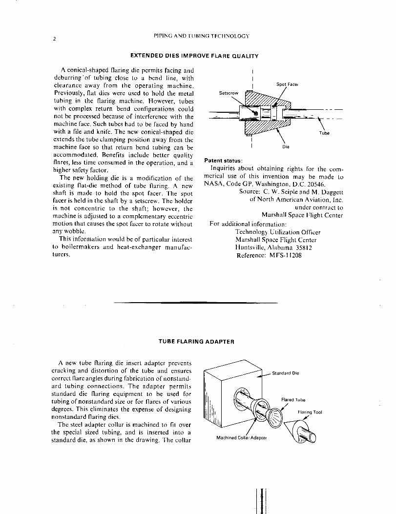
EXTENDED DIES IMPROVE FLARE QUALITY
A conical-shaped flaring die permits facing and
deburring'of tubing close to a bend line, with
clearance away from the operating machine.Previously, flat dies were used to hold the metal
tubing in the flaring machine. However, tubes
with complex return bend configurations could
not be processed because of interference with the
machine face. Such tubes had to be faced by hand
with a file and knife. The new conical-shaped die
extends the tube clamping position away from the
machine face so that return bend tubing can be
accommodated. Benefits include better qualityflares, less time consumed in the operation, and a
higher safety factor.
The new holding die is a modification of the
existing flat-die method of tube flaring. A new
shaft is made to hold the spot facer. The spotracer is held in the shaft by a setscrew. The holder
is not concentric to the shaft; however, the
machine is adjusted to a complementary eccentricmotion that causes the spot facer to rotate without
any wobble.
This information would be of particular interest
to boilermakers and heat-exchanger manufac-turers.
Setscrew_
Die
Patent status:
Inquiries about obtaining rights for the com-
merical use of this invention may be made toNASA, Code GP, Washington, D.C. 20546.
Source: C. W. Seiple and M. Daggettof North American Aviation, Inc.
under contract to
Marshall Space Flight Center
For additional information:
Technology Utilization Officer
Marshall Space Flight CenterHuntsville, Alabama 35812
Reference: MFS-i 1208
TUBE FLARING ADAPTER
A new tube flaring die insert adapter prevents
cracking and distortion of the tube and ensures
correct flare angles during fabrication of nonstand-
ard tubing connections. The adapter permits
standard die flaring equipment to be used fortubing of nonstandard size or for flares of various
degrees. This eliminates the expense of designing
nonstandard flaring dies.
The steel adapter collar is machined to fit over
the special sized tubing, and is inserted into a
standard die, as shown in the drawing. The collar
_... Standard Die
I, _ _ Flared Tube

PIPING AND TUBING TOOLS 3
also can be machined long enough to shim up the
existing gap between an odd size tubing and the
next larger standard hole in the die. The tubing tobe flared is inserted in the collar and the flare held
in the proper position in relation to the flaring
tool. The tubing is then flared to the desired
degree.
Patent status:
Inquiries about obtaining rights for the com-
mercial use of this invention may be made to
NASA, Code GP, Washington, D.C. 20546.
Source: Gordon R. Marrayof North American Aviation, Inc.
under contract to
Manned Spacecraft Center
For addition information:
Technology Utilization Officer
Manned Spacecraft CenterHouston, Texas 77058Reference: MSC-10034
PORTABLE DRILL GUIDE
A portable drill guide has been produced for
drilling holes in B-nuts and fittings where safety
wire holes have been omitted or damaged. Hand-
drilled holes often are inaccurate and a specific
edge distance is difficult to maintain.
The drill guide enables the drill operator toaccurately and easily bore the holes in B-nuts.
The size of the drill guide is determined by the
nut or fitting to be drilled.
Patent status :
Inquiries about obtaining rights for the com-mercial use of this invention may be made to
NASA, Code GP, Washington, D.C. 20546.
Source: G.S. Hollabaugh and W. Farmerof North American Aviation, Inc.
under contract to
Marshall Space Flight Center
Drill Guide=_.
Guide Hole to_
For additional information:
Technology Utilization Officer
Marshall Space Flight CenterHuntsville, Alabama 35812Reference: MFS-12909
INSTRUMENT TUBING FERRULE PULLER
An impact tool designed to remove sealing
ferrules from instrument tubing without damagingthem even permits resuse of ferrules which have
been crimped onto the tubing.
The flat, yoke-shaped tool has a slot of varyingwidth which accommodates three sizes of ferrules.
The tool is made of a material that is softer than
that of the ferrule. Soft aluminum is used to make
the tool for stainless steel or brass ferrules and
Lucite on micarta material is used for copper or
aluminum ferrules. The contacting edges of theyoke are slightly rounded to prevent local defor-
mation of the ferrule at the first point of contact.
The user simply positions the tool over the fer-
rule and makes several light taps on it with a
hammer, rotating the tool 30 to 45 degrees with

4 PIPING AND TUBING TECHNOLOGY
each impact. The impact loosens the ferrule for
removal or repositioning.
Patent status:
Inquiries about obtaining rights for the com-
mercial use of this invention may be made to
NASA, Code GP, Washington, D.C. 20546.Source: R. B. Schaus
of North American Aviation, Inc.under contract to
Marshall Space Flight Center
For additional information:
Technology Utilization Officer
Marshall Space Flight Center
Huntsville, Alabama 35812Reference: MFS-11533
Ferrule Puller
Tubing
_ Ferrule
11

Section 2--Special Piping and Tubing Devices
SPIRAL WOUND STRIPS
A spiral spacer-support for small vacuum-
jacketed pipelines has been designed that permitsan inner pipe to move axially and radially inde-
pendently of its vacuum jacket. The spiral also
provides thermal insulation between the inner and
outer pipelines, even during contraction and
expansion, or other movement which might causethe inner pipe to bottom out.
The spiral is fabricated from a 1/2-inch wide
strip of 1/16-inch thick stainless steel coated on
both sides with Teflon. For a 1-inch pipe inside a
2-inch jacket, a 20-inch strip is wound around a
3/4-inch diameter mandrel with a 5/8-inch deep
saw cut (to hold the stainless strip during wind-ing). A sizing guide made from a l/2-inch widestrip of paper pad cardboard is wound with the
stainless steel strip and later removed. Final sizing
of the spacer to the piping is accomplished by
trimming the exposed end.
A number of the spiral spacers are installed at
distances appropriate to support the weight of
the inner line. The spiral spacers also can bescaled up to fit larger diameter lines.
Patent status:
Inquiries about obtaining rights for the com-
mercial use of this invention may be made to
NASA, Code GP, Washington, D.C. 20546.Source: W. M. Bowers
of North American Aviation, Inc.under contract to
Marshall Space Flight Center
SUPPORT JACKETED PIPE
Axial Movement
\Teflon-coated Spiral
Inner Cryogenic
Flowline
\
Radial Movement
i/
J
Outer Cryogenic Jacket
For additional information:
Technology Utilization Officer
Marshall Space Flight CenterHuntsville, Alabama 35812Reference: MFS-12566

6 PIPINGANDTUBINGTECttNOLOGY
INERTANCE TUBE FOR GAS GENERATOR SYSTEMS
An inertance tube consisting of a length of
small cross-section tubing has been designed to
reduce buzz-type combustion instabilities associ-ated with gas generator operation. The tube uses
the high velocity of the fluid to cancel the force of
the pressure waves, and thus does not propagate
oscillation energy in either direction. Previously,
oscillation problems were reduced by redesign-
ing the injector and feed system.The inertance tube is installed in the line so
that it reflects any pressure waves back to the
injector without resonating at any of the natural
frequencies of the flame system. The tube is not a
tuned device, but the compressibility of the high
velocity fluid negates the inertance when the tube
is l/2-wavelength long, so that the highest wavefrequency which it will damp fully is that for
which the tube is l/4-wavelength long. The tube
has a range instead of just single wavelength capa-
bility in the case of a quarter-wave tube.
Patent status:
Inquiries about obtaining rights for the com-
mercial use of this invention may be made toNASA, Code GP, Washington, D.C. 20546.
Source: F. A. Jenningsof North American Aviation, Inc.
undei" contract to
Marshall Space Flight Center
Inertance Tube_
!l
For additional information:
Technology Utilization Officer
Marshall Space Flight Center
Huntsville, Alabama 35812Reference: M FS- 1842
PLUG FIXTURE USED TO LEAK TEST MULTIPLE PORTS
A fixture for hydrostatic pressure testing of
tubes uses elastic O-rings to temporarily seal
multiple open ports positioned radially in the
same plane within the pressure chamber. For such
tests, the smooth bore of the tube ports must notbe defaced, and no mechanical attachments can be
made to the exterior of the ports.
Each tube being tested is fitted with an alumi-
num plug insert grooved to receive an O-ring. TheO-ring forms a seal between the plug and chamber
port wall during testing. The plugs are long
O-Ring
x"
Alumin _
Plug
Plug
Tubes Under Test Reta tier
Chamber

SPECIAL PIPING AND TUBING DEVICES 7
enough so that they protrude from the chamber
ports for easy removal. To hold the plugs securely
in position under the hydrostatic pressure, a
circular angle iron retainer ring is placed over the
ends of all the plugs. A similar test fixture can be
adapted for use with pressure chamber vessels ofalmost any shape or size.
Patent status:
Inquiries about obtaining rights for the com-
mercial use of this invention may be made to
NASA, Code GP, Washington, D.C. 20546.Source: D. Milanovitch
of Aerojet-General Corporationunder contract to
AEC NASA Space Nuclear Propulsion Office
For additional information:
Technology Utilization Officer
AEC NASA Space
Propulsion OfficeU.S. Atomic Energy Commission
Washington, D.C. 20545Reference: NU-0056
TUBING SUPPORT ACTS
A tubing support has been designed to protect
tubing in pressurized systems that are subjected to
high vibrations and high temperatures. Previ-
out methods for supporting tubing of 1/4- toi-inch diameter under these conditions employed
rigid support blocks, often resulting in damage to
the lines and tubing. The new technique uses a
wire mesh material having a high coefficient of
friction which provides sufficient damping capa-
bility to prevent tube damage in a high-vibration,
high-temperature application.
The new support, shown in the figure, has wire-mesh clamps encircling the tubing within the
support blocks. The clamps are secured to the
tubing before the support is assembled.
This design was developed as a result of workon rocket engines and has application for similar
high-vibration tubing support requirements innonaerospace applications.
Patent status :
Inquiries about obtaining rights for the com-
mercial use of this invention may be made toNASA, Code GP, Washington, D.C. 20546.
Source: D. E. Kleinert
of North American Aviation, Inc.under contract to
Marshall Space Flight Center
For additional information:
Technology Utilization Officer
Marshall Space Flight CenterHuntsville, Alabama 35812
Reference: MFS-11920
AS VIBRATION DAMPER
i ! L Tubing
Wire Me _J

PIPING AND TUBING TECHNOLOGY8
CABLE-TO-TUBE FASTENER PROTECTS BOTH
A fastener made of molded flexible plastic
permits cable to be held snugly to tubing thereby
reducing or preventing damage to either which
might occur when the assembly is subjected totorsional stresses. The design and flexibility of
the plastic fastener permit it to be used to hold
any size of tubing and cable.There are two ways in which the fastener can be
used. It can be fastened first to a tube by means
of a tie cord passed through a slotted hole in its
vertical flange, then the cable may be attached
alongside the flange. When used in this way, the
fastener provides some insulation between thecable and the tube. The fastener also can be used to
encompass both the cable and the tube, when theyare attached to each other, to act as a suspension
medium from a structure.
Patent status:
Inquiries about obtaining rights for the com-mercial use of this invention may be made to
NASA, Code GP, Washington, D.C. 20546.Source: W.E. Pierce
" <'i J_--
_/.- ube
,,o,,e,,o,,,\\/'//_"'{(/_._)/_/ Cableor TieCord
For additional information:
Technology Utilization Officer
Jet Propulsion Laboratory4800 Oak Grove Drive
Pasadena, California 91103
Reference: JPL-752
It

Section 3--Special Piping and Tubing Techniques
TUBE TAPERING BY ELECTROCHEMICAL PROCESS
An electrochemical process tapers tubes on the
outside diameter only, without inducing internalstresses and strains which result in distortions of
the metal. Also, small diameter, thin-wall tubingis usually difficult to machine due to its lack of
rigidity.
The lower portion ofthe tube tapering unit con-
tains a watertight enclosure in which the tubes are
inserted vertically through a tooling plate. Thetubes are plugged at both ends and held to tube
holding plates by O-rings. The top tube holdingplate and tubes are electrically designated as the
anode (or positive terminal), while the tooling
plate is the cathode (or negative terminal). An
electrolyte is circulated through the enclosure con-
taining the tubes. By adjusting the current appliedfrom the anode to the cathode, the metal is
removed from the tubes at varying rates by a
deplating process. Synchronizing the withdrawal
rate of the tubes and the applied electrical current
produces tapers of any desired configuration onthe outside diameter of the tube.
Patent status:
Inquiries about obtaining rights for the com-
mercial use of this invention may be made to
NASA, Code GP, Washington, D.C. 20546.Source: Howard D. Lesher
of North American Aviation, Inc.under contract to
Marshall Space Flight Center
Motor
Current
To DC
Power Supply
Tube Holding
Plate (Positive
Electrode)
From DC
Power Supply
Electr(
Solution
Electrolyte
In
Pump and
Filter Unit
Tooling Plate
(Negative Electrode)
ectrolyte
Out
Tube
Holding Plate
For additional information:
Technology Utilization Officer
Marshall Space Flight CenterHuntsville, Alabama 35812Reference: MFS-747

PIPING AND TUBING TECFINOLOGY10
TUBE SIZING PROCEDURE CHANGES INTERNAL CONFIGURATION
An economical tube sizing procedure has been
devised for producing an accurate, constant outer-
diameter tube having a stepped inner-diameter
wall thickness. The method involves grinding the
desired internal configuration on the outer diam-
eter of the tube, and transferring it to the inner
diameter by means of a drawing operation.The procedure involves the three-step operation
shown in the figure. A solid steel mandrel is
inserted into the tube to remove any ovality orout-of-round variations, and the outer diameter
is centerless ground to the desired specifications,
as shown in Step A. A mandrel of the shape de-sired is then inserted in the tube, and the tube is
pulled through a draw die to transfer the configu-rations from the outer diameter to the inner
diameter (Step B). In the final operation (Step C),the tube is centerless ground to remove any extrawall thickness.
This method can be used by tube manufactur-
ers (for metallic or plastic tubes) to produce
accurate internal configurations.
Patent status:
Inquiries about obtaining rights for the com-mercial use of this invention may be made to
NASA, Code GP, Washington, D.C. 20546.
Source: C. F. Kennedy
of North American Aviation, Inc.under contract to
Marshall Space Flight Center
Centerless Grind
Tube STEP A Solid Mandrel
Draw Chuck
Draw Die _
Machined MandrelSTEP B
Centerless Grind
.K...,_'J"_ Any Excess
/'STEP C
Tube
For additional information:
Technology Utilization Officer
Marshall Space Flight CenterHuntsville, Alabama 35812Reference: MFS-12158

SPECIAL PIPING AND TUBING TECHNIQUES 11
ORIFICE TUBING INSTALLATION SIMPLIFIED
A method using helium arc welding has been
devised to permit air-flow orifice tubing to beinstalled in wind-tunnel airfoil models, without
causing dimples or distortions in the airfoil sur-
face. The previous method of tubing installationused silver-soldering techniques. These techniques
resulted in airfoil surface distortion, poor me-
chanical bonding, and excessive slag deposits.
The drawing shows the difference between
helium arc welding over the silver soldering tech-
nique. In the helium arc method, a small metal
washer is employed as a welding guide or dam.The washer restricts the amount of welding
residue which is deposited on the airfoil surface,and also functions as a heat sink.
The tubing is inserted through the drilled orifice
in the airfoil. The washer is positioned around
the orifice and the projecting tubing is melted bythe heat of the l_elium arc process into the orifice.
A hole, corresponding to the inside diameter of
the tubing, then is drilled through the welded
area. The airfoil surface surrounding the drilled
hole is then machined to the proper plane.Source: C. Thiele
Surface Outline AfterConventional
Helium-Arc Welding Silver Solder
Washer _ Weld
_Steel Tubing
For additional information:
Technology Utilization Officer
Langley Research Center
Langley Station
Hampton, Virginia 23365Reference: LAR-10029

'12 PIPINGANDTUBINGTECHNOLOGY
ROLLING TUBING INTO COILS
A quick and efficient method has been de-
veloped for rolling long lengths of small diameter
soft copper tubing into small diameter coils. The
method permits sections of tubing of up to 50 feet
in length to be rolled into coils without damage tothe tube.
The former procedure of rolling coils includedfilling and packing the small diameter tubing with
sand, prior to the bending operation. This proced-
ure thereby limited the tubing length to no more
than 25 feet. Also, extensive cleaning was requiredto remove the sand from the formed coil.
In the new method, the tubing is filled with
water and hydrostatically pressurized. A pressure
of 1000 psi is used for tubing having 0.035-inch
wall thickness, and 3/8- to l/2-inch outer diam-
eter. The tubing then can be rolled without distor-
tion or crimping. Also, the new method eliminatesthe need for cleaning the coiled tubing.
Source: M. E. Call
For additional information:
Technology Utilization Officer
Langley Research Center
Langley Station
Hampton, Virginia 23365Reference: LAR-216
11

Section 4--Piping Joints and Disconnects
MACHINED BELLOWS FOR HIGH PRESSURE SYSTEMS
A low height bellows has been designed for high
pressure, large flowrate, connector systems to
provide greater flexibility in gimbal joints.
The compact bellows is constructed from stain-
less steel alloy to provide a gimbal joint which
permits manual operation in a corrosive environ-ment. The bellows convolution is machined for
heavy roots and crests to withstand hoop pres-
sures (figure A); and the sidewalls are thin to
allow a higher cycle life. In addition, the bellows
is compressed axially at approximately 35,000 psig
to give it a permanent set that lowers operatingstresses and increases stability.
Figure B shows a configuration of three gimbal
joints, each using the bellows to provide the major
portion of angulation for the entire connectorsystem. The system provides an angulation capa-
bility equivalent to a twelve inch cube, with each
bellows able to withstand 50,000 angulations at
10,000 psig operating pressure.
Bellows of this type could be used in gimbal
joints and pressure balance compensators of highpressure piping systems, such as those used in the
chemical and petroleum industries.
Patent status"
Inquiries about obtaining rights for the com-
mercial use of this invention may be made toNASA, Code GP, Washington, D.C. 20546.
Source: International Harvester Companyunder contract to
Kennedy Space Center
Root _ _ Fig_reA
SidewallBellows Crest
Bellows
Figure B
Bellows
For additional information:
Technology Utilization Officer
Kennedy Space Center
Kennedy Space Center, Florida 32899Reference: KSC-09952
13

14 PIPINGANDTUBINGTECHNOLOGY
MODULAR EXPANSION JOINT REPAIR KIT
A modular repair kit for expansion joints in
cryogenic transfer lines permits replacement inthe line while requiring a minimum amount of
spares to be kept in stock. With the modular kit,
a determined number of "building block" bellows
can be used singly or in multiples to replace any
joint in the system. Previously, to minimize system
downtime for the replacement of joints, a com-
plete set of spares had to be kept on inventory,
involving a high investment.Content of the kit is determined by the charac-
teristics of each expansion joint in the systemand the "lowest common denominator" bellows
that satisfies the smallest travel requirement when
used singly, or the largest travel requirementwhen used in multiples. For example, the figure
shows both the simplest and most complex joints
in a particular 6-inch liquid oxygen transfer line
containing 13 dissimilar expansion joints. The
modular repair kit for this system consists of the
following components: two single bellows units,
each with one restrainer ring; one dual bellowsunit with three restrainer rings; and one separate
restrainer ring. These components, used singly or
all welded together, can be used to make either
joint shown in the figure or a joint intermediateto either.
Patent status:
Inquiries about obtaining rights for the com-
mercial use of this invention may be made to
CompressionRestrainerTube TensionRestrainerRod
RestrainerNu_
Bueliltow_ _'_RestrainerRing
SimpleJoint
ComplexJoint
NASA, Code GP, Washington, D.C. 20546.Source: R. M. Kuhar
of North American Aviation, Inc.under contract to
Marshall Space Flight Center
For additional information:
Technology Utilization Officer
Marshall Space Flight CenterHuntsville, Alabama 35812Reference: MFS-11758

PIPING JOINTS AND DISCONNECTS 15
DISCONNECT JOINT PERMITS HIGH MISALIGNMENT
A new disconnect joint provides uninterrupted
high-pressure fluid flow past a large relative
movement interface. The joint accommodates
angular misalignments, and replaces the less
rugged flexible hose which usually is applied insuch case.
The disconnect, constructed of aluminum, is a
double ball and socket spherical joint arrange-
ment. One ball is attached to a tubular probe. Theprobe fits into a receptacle in the other ball and
socket which also is equipped with a spring loaded
poppet. The poppet is controlled by the probe,being forced open for fluid flow when the two
parts are mated and closed when the probe is
removed so that further fluid flow is stopped.The prototype joints which were tested have
±10 degree angular, and 0.58-inch lateral mis-
alignment capability. The baH, socket, and other
working parts have a hard anodic coating 0.001inch in thickness. Standard O-rings are used for
all seals. The poppet conical seal, installed under
35"_ diametral compression was found to be 100°/
effective at pressures of up to 3360 psi. This typeof joint may be used in many applications as a
quick disconnect device or where misalignment in
pneumatic or hydraulic pressure lines may occur.
Tubular Probe Ball and Probe
Receptacle
0
Ball and
Socket
Poppet Seal O-Ring Poppet
Patent status:
Inquiries about obtaining rights for the com-mercial use of this invention may be made to
NASA, Code GP, Washington, D.C. 20546.Source: E. H. Bock
of General Dynamics Corporationunder contract to
Lewis Research Center
For additional information:
Technology Utilization OfficerLewis Research Center
21000 Brookpark RoadCleveland, Ohio 44135Reference: LEW-10002
MOUNTING ASSEMBLY AIDS INSTALLATION OF FLUID LINE DISCONNECTS
An adjustable mounting assembly for fluid line
disconnects has clearances to provide for mis-alignment or differential movement between the
support and the mating parts of the disconnect,
and thereby facilitates its mounting or installa-
tion. The assembly also provides a mechanical
means of pushing together the mating parts ofthe disconnect.
The mounting assembly, shown in the figure
along with the mating sections of a fluid line dis-
connect, consists of a mounting bushing, anadjusting support ring, a lock ring, a boot, and a
boot retainer. The parts are used to install a dis-
connect onto a plate by the following procedure:
First, the mounting bushing is bolted onto the
plate. The adjusting support ring is then screwed
into the mounting bushing until its threads bot-
tom out. The lock ring and boot are positioned
onto the disconnect receptacle and the receptacleis inserted through the adjusting support ring and
engaged with the disconnect socket. The adjusting
support ring is then backed out (rotated counter-
clockwise) until its flange touches the disconnect
flange on the disconnect receptacle. The adjusting
support ring is screwed back in two turns so thatenough clearance is provided for thermal shrink-
age which may occur during the loading of cryo-
genic fluids. While the adjusting support ring is

16 PIPING AND TUBING TECHNOLOGY
held firmly, the lock ring is screwed into it until
the lock ring just touches the disconnect flange.
The boot is then bolted to the lock ring by theboot retainer.
The contact between the lock ring and discon-
nect flange prevents inadvertent unlocking of thedisconnect by vibration. If the disconnect is dif-
ficult to lock together, it may be mated to the
socket by screwing the lock ring into the adjusting
support ring.
The mounting assembly may be used in any
piping system where disconnects are used.
Patent status:
Inquiries about obtaining rights for the com-
mercial use of this invention may be made to
NASA, Code GP, Washington, D.C. 20546.Source: P. L. Clemensen and J. P. Doelger
of North American Aviation, Inc.under contract to
Marshall Space Flight Center
For additional information:
Technology Utilization Officer
Marshall Space Flight Center
Huntsville, Alabama 35812Reference: MFS-11565
Disconnect Socket
Adjusting Ring
Mounting
Bushing
Lock Rim
Boot Retainer
Boot
Hose
LOW PRESSURE PNEUMATIC QUICK DISCONNECT
A quick release device disconnects soft plastictubing from rigid metal tubing in vacuum or low-
pressure lines. A simple version consists of a hard
washer that has an outer diameter large enough to
be pushed by a workman's fingers, as shown in
Figure A. This disconnect is useful especially incases where base clamps have partially fused the
soft tubing or hose to the rigid surface of the
mating tubing.
Figure B shows a quick disconnect that uses aformed wire stripper and a lanyard to release the
soft tubing from a metal mating surface. A short
section of plastic tubing is attached permanently
.. Metal Tubing
J Quick Disconnect _ _." "_Pressure
Applied withFingers Figure A

PIPING JOINTS AND DISCONNECTS 17
with a clamp to one end of an open tube line. The
stripper and lanyard are placed on the connectingtube line so that when the lanyard is pulled, the
stripper compresses the plastic tubing against
the clamp. This causes the inner diameter of the
plastic to stretch and increase, thereby permittingit to slide off the mating metal tube.
Variations of this device can be used on tubing
in situations that require frequent dissassembly,
cleaning, or sterilizing.Source: R. M. Overdeer
of General Dynamics Corporationunder contract to
Lewis Research Center
For additional information:
Technology Utilization OfficerLewis Research Center
21000 Brookpark RoadCleveland, Ohio 44135Reference: LEW-10017
Stripper_
[,y_'_ Metal Tube
Lanyard _." _ /_\\ ".\.'l
Metal Tube
Figure g
NASA-Langley, 1967


Ii