pipe sizing based on the 2015 ifgc and irc - iccsafe.org · ifgc section 402.4.2/irc section...
TRANSCRIPT

1
CodeNotes is provided courtesy of the
ICC PMG Official Membership Council
Introduction:This CodeNotes™ provides an overview of pipe sizing calculations and requirements in the 2015 International Fuel Gas Code® (IFGC®) and 2015 International Residential Code (IRC®). It will cover both the longest length method and the branch length method. Applicable code tables, figures and example problems and solutions are provided for each method to help the reader easily understand the pipe sizing methodology.
General Criteria and Related InformationTo determine the demand volume required by an appliance in cubic feet (m3) of gas per hour, the maximum input rating of the appliance must be used. This is provided by the appliance manufacturer in British thermal units per hour [Btu/h-(W)] as specified by the appliance manufacturer. If the average heating value per unit of fuel is known [about 1,000 Btu/ft3 (37.3 MJ/m3) for natural gas], the volume of gas required per hour can be calculated. The heating value can be obtained from the gas supplier. The IFGC requires the input rating of all appliances be shown on the appliance label. Figure 1 shows a typical example of a partial appliance label. When the input rating of the appliances is unknown at the time of the piping system design, the gas demand must be estimated based on input from appliance manufacturers, gas utilities or other sources, see Table 1: Estimated Input for Initial Design Purposes. The load on the piping system must be based on the simultaneous operation of all appliances at full output. While estimated input ratings can be used for initial system designs, pipe sizing must be verified once the actual appliances and their input ratings are known.
If a designer fails to verify the sizing with the actual connected load values, the resulting system could be undersized. In all cases, the fuel gas supply piping must have the capacity to supply the actual connected load of the appliances installed.
IFGC Section 402.4.1/ IRC Section G2413.4.1 Longest Length MethodThis section of the IFGC/IRC provides a step-by-step approach for the longest length method.
First, determine the maximum pipe length from the point of delivery to the farthest outlet.
Second, determine the equivalent length of all fittings and add it to the pipe length to get the total determined length. This is typically done on a piping run having four or more fittings. Many designers simply add 50 percent of the actual length of piping as an all-inclusive fitting allowance (i.e., actual pipe length x 1.50).
Third, determine the maximum piping system load by adding the maximum input rating of all appliances to be connected to the system. Divide that value by the heating value of the gas to get the maximum demand volume of the system in cubic feet of gas per hour.
Fourth, locate the appropriate sizing table, see Table 2: IFGC Table 402.4(2)/IRC, Table G2413.4(1), based on the type of pipe, gas, inlet pressure and pressure drop. Select the row in the table that equals the determined length, or the next higher row if the length is between table values. Then select the column in that row that equals the maximum demand of the system. If the value is between columns, select the next larger column. Once the appropriate box in the table is located, the pipe size can be found in that column at the top of the table.
CodeNotes ™
Pipe Sizing Based on the 2015 IFGC® and IRC®
STEP 1: Maximum Pipe Length
STEP 2: Equivalent Length of Fittings
STEP 4: Determine Pipe Size
STEP 3: Maximum Demand Volume
RECOVERY RATING based on 100 deg. F rise 33.9 GPH
MINIMUM SUPPLY PRESSURE 6″ w.c. w.c. MANIFOLD PRESSURE 5″
INPUT RATING-BTU/HR 40,000 CAPACITY 50 US GALLONS
Figure 1 Partial View of an Appliance Label
2
All piping in the system should then be constructed using piping of the size derived from the table. Basing the sizing on the most demanding circuit (longest run) compensates for pressure losses throughout the entire system (see Figure 2 and Table 3).
TABLE 1: ESTIMATED INPUT FOR INITIAL DESIGN PURPOSES. This table is from Annex A of the Natural Fuel Gas Code (ANSI 273.1).
APPLIANCE INPUT BTU/H (APPROX.)
Space Heating Units
Hydronic boiler
Single family
Multiple family, per unit
Warm-air furnace
Single family
Multiple family, per unit
100,000
60,000
100,000
60,000
Space and Water Heating Units
Hydronic boiler
Single family
Multiple family, per unit
120,000
75,000
Water Heating Appliances
Water heater, automatic instantaneous
Capacity at 2 gal./minute
Capacity at 4 gal./minute
Capacity at 6 gal./minute
Water heater, automatic storage, 30- to 40-gal. tank
Water heater, automatic storage, 50-gal. tank
Water heater, domestic, circulating or side-arm
142,800
285,000
428,400
35,000
50,000
35,000
Cooking Appliances
Built-in oven or broiler unit, domestic
Built-in top unit, domestic
Range, free-standing, domestic
25,000
40,000
65,000
Other Appliances
Barbecue
Clothes dryer, Type 1 (domestic)
Gas fireplace, direct-vent
Gas light
Gas log
Refrigerator
40,000
35,000
40,000
2,500
80,000
3,000
For SI: 1 British thermal unit per hour = 0.2931 W.
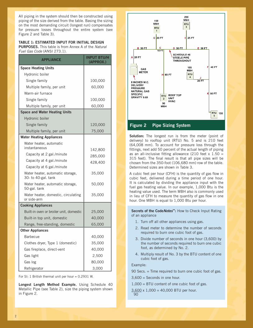
Longest Length Method Example. Using Schedule 40 Metallic Pipe (see Table 2), size the piping system shown in Figure 2.
Solution: The longest run is from the meter (point of delivery) to rooftop unit (RTU) No. 5 and is 210 feet (64,008 mm). To account for pressure loss through the fittings, next add 50 percent of the actual length of piping as an all-inclusive fitting allowance (210 feet x 1.50 = 315 feet). The final result is that all pipe sizes will be chosen from the 350-foot (106,680 mm) row of the table. Determined sizes are shown in Table 3.
A cubic feet per hour (CFH) is the quantity of gas flow in cubic feet, delivered during a time period of one hour. It is calculated by dividing the appliance input with the fuel gas heating value. In our example, 1,000 Btu is the heating value used. The term MBH also is commonly used in lieu of CFH to measure the quantity of gas flow in one hour. One MBH is equal to 1,000 Btu per hour.
Secrets of the CodeNotes™: How to Check Input Rating of an appliance
1. Turn off all other appliances using gas.
2. Read meter to determine the number of seconds required to burn one cubic foot of gas.
3. Divide number of seconds in one hour (3,600) by the number of seconds required to burn one cubic foot, as determined by No. 2.
4. Multiply result of No. 3 by the BTU content of one cubic foot of gas.
Example:
90 Secs. = Time required to burn one cubic foot of gas.
3,600 = Seconds in one hour.
1,000 = BTU content of one cubic foot of gas.
3,600 x 1,000 = 40,000 BTU per hour.90
Figure 2 Pipe Sizing System
3
See Table 3 below for the final pipe sizes and load for each section of pipe in Figure 2.
TABLE 3: FIGURE 2 SOLUTION
PIPE SECTION LOAD (CFH) SIZE (in.)
A 690 2½
B 690 2½
C 540 2
D 450 2
E 250 1½
F 250 1½
G 150 1¼
H 90 1
I 200 1¼
J 100 1¼
K 150 1¼
Example: Input, Btu/h ÷ Heating Value (1,000) = CFH)
Other than a very limited exception for minor components, all installation, enlargement, alteration, repair, removal, conversion or replacement of fuel gas piping will require a permit.
IFGC Section 402.4.2/IRC Section G2413.4.2 Branch Length Method. This sizing method is a variation of the longest-length method. Because this method is less conservative, it is especially important to account for the equivalent length of fittings installed in the system (see Figure 3). This method involves multiple piping lengths within a system for application of the tables or equations, whereas the longest length method involves only one piping length per system.
Figure 3 Branch Length Method
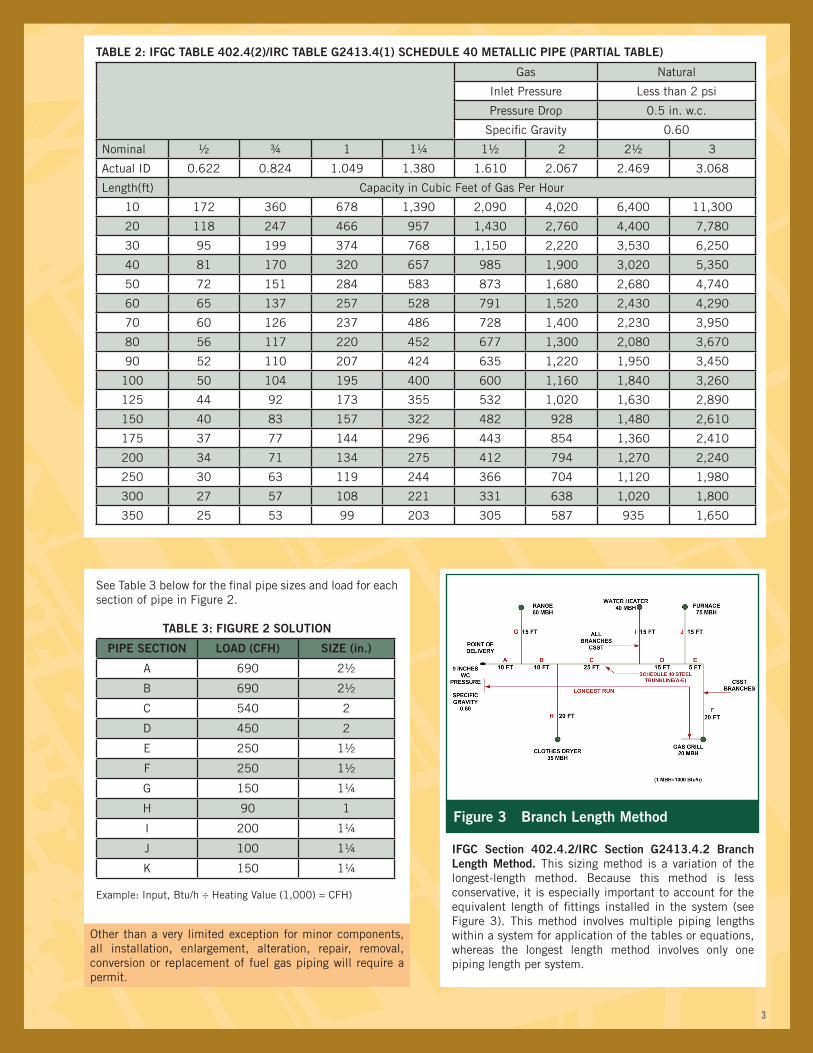
TABLE 2: IFGC TABLE 402.4(2)/IRC TABLE G2413.4(1) SCHEDULE 40 METALLIC PIPE (PARTIAL TABLE)
Gas Natural
Inlet Pressure Less than 2 psi
Pressure Drop 0.5 in. w.c.
Specific Gravity 0.60
Nominal ½ ¾ 1 1¼ 1½ 2 2½ 3
Actual ID 0.622 0.824 1.049 1.380 1.610 2.067 2.469 3.068
Length(ft) Capacity in Cubic Feet of Gas Per Hour
10 172 360 678 1,390 2,090 4,020 6,400 11,300
20 118 247 466 957 1,430 2,760 4,400 7,780
30 95 199 374 768 1,150 2,220 3,530 6,250
40 81 170 320 657 985 1,900 3,020 5,350
50 72 151 284 583 873 1,680 2,680 4,740
60 65 137 257 528 791 1,520 2,430 4,290
70 60 126 237 486 728 1,400 2,230 3,950
80 56 117 220 452 677 1,300 2,080 3,670
90 52 110 207 424 635 1,220 1,950 3,450
100 50 104 195 400 600 1,160 1,840 3,260
125 44 92 173 355 532 1,020 1,630 2,890
150 40 83 157 322 482 928 1,480 2,610
175 37 77 144 296 443 854 1,360 2,410
200 34 71 134 275 412 794 1,270 2,240
250 30 63 119 244 366 704 1,120 1,980
300 27 57 108 221 331 638 1,020 1,800
350 25 53 99 203 305 587 935 1,650

Please contact the International Code Council to order the International Fuel Gas Code, International Residential Code, Code and Commentary series or other code support publications.
www.iccsafe.org/store | 1-800-786-4452
Copyright© 2016International Code Councilwww.iccsafe.org1-888-422-ICC-SAFE(422-7233)
4
TABLE 4: [IFGC TABLE 402.4(15)/IRC TABLE G2413.4(5) CORRUGATED STAINLESS STEEL TUBING (CSST) (PARTIAL TABLE)
TUBE SIZE (EHD)
FlowDesignation
13 15 18 19 23 25 30
Length (ft) Capacity in Cubic Feet of Gas Per Hour
5 46 63 115 134 225 270 471
10 32 44 82 95 161 192 330
15 25 35 66 77 132 157 267
20 22 31 58 67 116 137 231
25 19 27 52 60 104 122 206
30 18 25 47 55 96 112 188
40 15 21 41 47 83 97 162
50 13 19 37 42 75 87 144
60 12 17 34 38 68 80 131
70 11 16 31 36 63 74 121
80 10 15 29 33 60 69 113
90 10 14 28 32 57 65 107
100 9 13 26 30 54 62 101
For SI: 1 inch = 25.4 mm, 1 foot = 304.8 mm, 1 pound per square inch = 6.895 kPa, 1 inch water column = 0.2488 kPa, 1 British thermal unit per hour = 0.2931 W, 1 cubic foot per hour = .0283 m3/h, 1 degree = 0.0 1745 rad.
Notes:1. Table includes losses for four 90-degree bends and two end fittings. Tubing runs with larger numbers of bends and/or fittings shall be
increased by an equivalent length of tubing to the following equation: L = 1.3n, where L is additional length (feet) of tubing and n is the number of additional fittings and/or bends.
2. EHD—Equivalent Hydraulic Diameter, which is a measure of the relative hydraulic efficiency between different tubing sizes. The greater the value of EHD, the greater the gas capacity of the tubing.
3. All table entries have been rounded to three significant digits.
In accordance with Section 402.4.2 Item 2, determine the size of Branch Sections F, G, H, I and J (constructed of CSST) based on the load of each section and the length of piping and tubing from the point of delivery to the outlet on that section. Table 4 is chosen because the branch sections are constructed of CSST and the pressure is less than 0.5 psi [(14 in. w.c) (3.5 kPa)]. Where a length falls between entries in the table, use the next longer length row. See Table 5 and Table 6 for the final pipe sizes and load for each section of pipe in Figure 3.
TABLE 5: SOLUTION A
PIPE SECTION LOAD (CFH) SIZE (IN.)
A 230 1¼
B 170 1
C 135 1
D 95 ¾
E 20 ³/8
www.aga.org • 202-824-7000
CSST is Corrugated Stainless Steel Tubing. It consists of continuous, semi-rigid stainless steel tube with an outer yellow or black plastic jacket covering. Yellow-jacketed CSST was developed first and is the most common. It has a non-conductive plastic yellow jacket. Black-jacketed CSST is relatively new. Its black jacket is electrically conductive. Manufacturer information indicates this conductive jacket dissipates the energy of indirect lightning strikes that might otherwise pierce or damage the yellow-jacketed CSST.
TABLE 6: SOLUTION B
CSSTBRANCH
LOAD (CFH) LENGTH PIPING
AND TUBING
(FT)
SIZE EHD
F 20 85 18
G 60 25 19
H 35 40 18
I 40 60 23
J 75 75 30