pipe riser isolation selection guide -...
TRANSCRIPT
kineticsnoise.com
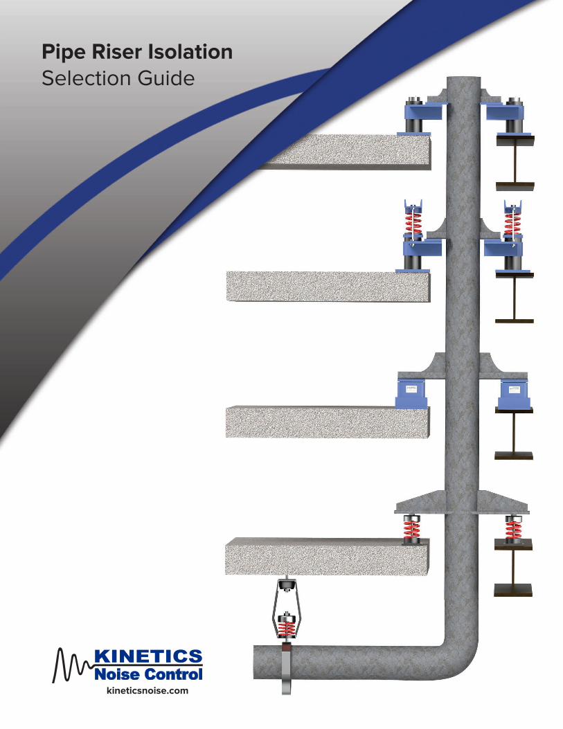
Pipe Riser IsolationSelection Guide

2
• Pipe Isolation Design• Pipe Support Design• Seismic / Wind Restraint Design• Thermal Stress Analysis• Expansion Requirements and Design• ASME B31.3 code design and certification• ASCE 7 code design and certification• Commercial / Industrial / Residential Design• Water, Steam, Medical Gas piping
Vibration Isolators as Pipe Riser Supports
Vertical pipe risers can create a unique set of problems when they are installed in multi- story buildings. The introduction of fluids into the pipe can generate significant forces with-in the building at the riser support locations. Thermal expansion/contraction from steam or hot/cold water systems will cause the overall length of the piping to change. If not designed properly these changes can lead to substantial forces being transferred into the building structure, unacceptably high stress levels within the walls of the pipe, or failure of restraint and system components.
RISER DESIGN
PIPESTRESSANALYSIS
KINETICS® Engineering Solutions
Featured in this brochure are six standard riser support configurations Kinetics Noise Control design to assist building engineers efficiently and cost effectively design riser systems. Kinetics engineers are available to provide piping solutions for residential, commercial, and industrial applications from basic to complex. From pipe rack design to equipment room layouts, to piping system analysis, Kinetics Noise control delivers solutions.
FDS
KRG
KPA
FLSS
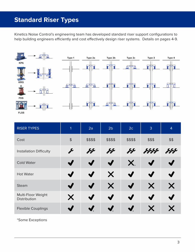
Kinetics Noise Control’s engineering team has developed standard riser support configurations to help building engineers efficiently and cost effectively design riser systems. Details on pages 4-9.
Type 2aType 1 Type 2b Type 2c Type 3 Type 4
RISER TYPES
Cost
Installation Difficulty
Cold Water
Hot Water
Steam
Multi-Floor WeightDistribution
Flexible Couplings
*Some Exceptions
1
$
2a
$$$$
2b
$$$$
2c
$$$$
3
$$$
4
$$
*
*
Standard Riser Types
3
* *
Cost
$
Installation Difficulty
Multi-Floor Weight
DistributionSteamHot
WaterColdWater
FlexibleCouplings
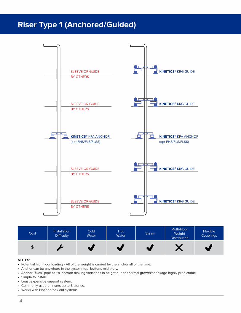
SLEEVE OR GUIDE
BY OTHERS
SLEEVE OR GUIDE
BY OTHERS
SLEEVE OR GUIDE
BY OTHERS
SLEEVE OR GUIDE
BY OTHERS
KINETICS® KPA ANCHOR
(opt FHS/FLS/FLSS)
KINETICS® KPA ANCHOR
(opt FHS/FLS/FLSS)
KINETICS® KRG GUIDE
KINETICS® KRG GUIDE
KINETICS® KRG GUIDE
KINETICS® KRG GUIDE
NOTES:• Potential high floor loading - All of the weight is carried by the anchor all of the time.• Anchor can be anywhere in the system: top, bottom, mid-story.• Anchor “fixes” pipe at it’s location making variations in height due to thermal growth/shrinkage highly predictable.• Simple to install.• Least expensive support system.• Commonly used on risers up to 6 stories.• Works with Hot and/or Cold systems.
4
Riser Type 1 (Anchored/Guided)

NOTES:• Balanced floor loading.• Anchor located at mid-story.• Reduces stress on piping.• Anchor “fixes” pipe at it’s location making variations in height due to thermal growth/shrinkage highly predictable.• Simple to install.• Most expensive support system.• Works with Hot and/or Cold systems.
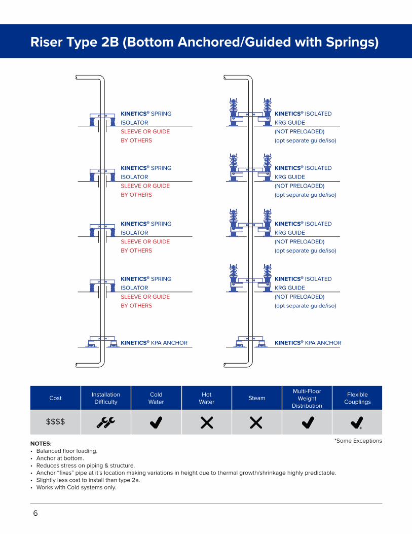
KINETICS® SPRING
ISOLATOR
SLEEVE OR GUIDE
BY OTHERS
KINETICS® SPRING
ISOLATOR
SLEEVE OR GUIDE
BY OTHERS
KINETICS® SPRING
ISOLATOR
SLEEVE OR GUIDE
BY OTHERS
KINETICS® SPRING
ISOLATOR
SLEEVE OR GUIDE
BY OTHERS
KINETICS® KPA ANCHOR KINETICS® KPA ANCHOR
KINETICS® ISOLATED
KRG GUIDE
(NOT PRELOADED)
(opt separate guide/iso)
KINETICS® ISOLATED
KRG GUIDE
(NOT PRELOADED)
(opt separate guide/iso)
KINETICS® ISOLATED
KRG GUIDE
(NOT PRELOADED)
(opt separate guide/iso)
KINETICS® ISOLATED
KRG GUIDE
(NOT PRELOADED)
(opt separate guide/iso)
Cost
$$$$
Installation Difficulty
Multi-Floor Weight
DistributionSteamHot
WaterColdWater
FlexibleCouplings
*Some Exceptions
*
5
Riser Type 2A (Anchored/Guided with Springs)
KINETICS® SPRING
ISOLATOR
SLEEVE OR GUIDE
BY OTHERS
KINETICS® SPRING
ISOLATOR
SLEEVE OR GUIDE
BY OTHERS
KINETICS® KPA ANCHOR
KINETICS® SPRING
ISOLATOR
SLEEVE OR GUIDE
BY OTHERS
KINETICS® SPRING
ISOLATOR
SLEEVE OR GUIDE
BY OTHERS
KINETICS® ISOLATED
KRG GUIDE
(NOT PRELOADED)
(opt separate guide/iso)
KINETICS® ISOLATED
KRG GUIDE
(NOT PRELOADED)
(opt separate guide/iso)
KINETICS® ISOLATED
KRG GUIDE
(NOT PRELOADED)
(opt separate guide/iso)
KINETICS® KPA ANCHOR
KINETICS® ISOLATED
KRG GUIDE
(NOT PRELOADED)
(opt separate guide/iso)
Cost
$$$$
Installation Difficulty
Multi-Floor Weight
DistributionSteamHot
WaterColdWater
FlexibleCouplings
NOTES:• Balanced floor loading.• Anchor at bottom.• Reduces stress on piping & structure.• Anchor “fixes” pipe at it’s location making variations in height due to thermal growth/shrinkage highly predictable.• Slightly less cost to install than type 2a.• Works with Cold systems only.
Riser Type 2B (Bottom Anchored/Guided with Springs)
6
*Some Exceptions
*

KINETICS® KPA ANCHOR
KINETICS® SPRING
ISOLATOR
SLEEVE OR GUIDE
BY OTHERS
KINETICS® SPRING
ISOLATOR
SLEEVE OR GUIDE
BY OTHERS
KINETICS® SPRING
ISOLATOR
SLEEVE OR GUIDE
BY OTHERS
KINETICS® SPRING
ISOLATOR
SLEEVE OR GUIDE
BY OTHERS
KINETICS® ISOLATED
KRG GUIDE
(NOT PRELOADED)
(opt separate guide/iso)
KINETICS® KPA ANCHOR
KINETICS® ISOLATED
KRG GUIDE
(NOT PRELOADED)
(opt separate guide/iso)
KINETICS® ISOLATED
KRG GUIDE
(NOT PRELOADED)
(opt separate guide/iso)
KINETICS® ISOLATED
KRG GUIDE
(NOT PRELOADED)
(opt separate guide/iso)
NOTES:• Balanced floor loading.• Anchor at top• Moderate stress on piping & structure.• Anchor “fixes” pipe at it’s location making variations in height due to thermal growth/shrinkage highly predictable.• Slightly less cost to install than type 2a.• Works with Hot systems only.
Cost
$$$$
Installation Difficulty
Multi-Floor Weight
DistributionSteamHot
WaterColdWater
FlexibleCouplings
*Some Exceptions
Riser Type 2C (Top Anchored/Guided with Springs)
7
**
Cost
$$$
Installation Difficulty
Multi-Floor Weight
DistributionSteamHot
WaterColdWater
FlexibleCouplings
NOTES:• Balanced floor loading.• Reduces stress on piping.• Most expensive support system.• Works with Hot and/or Cold systems.
KINETICS® SPRING
ISOLATOR
SLEEVE OR GUIDE
BY OTHERS
KINETICS® SPRING
ISOLATOR
SLEEVE OR GUIDE
BY OTHERS
KINETICS® SPRING
ISOLATOR
SLEEVE OR GUIDE
BY OTHERS
KINETICS® SPRING
ISOLATOR
SLEEVE OR GUIDE
BY OTHERS
KINETICS® SPRING
ISOLATOR
SLEEVE OR GUIDE
BY OTHERS
KINETICS® ISOLATED
KRG GUIDE
KINETICS® ISOLATED
KRG GUIDE
KINETICS® ISOLATED
KRG GUIDE
KINETICS® ISOLATED
KRG GUIDE
KINETICS® ISOLATED
KRG GUIDE
8
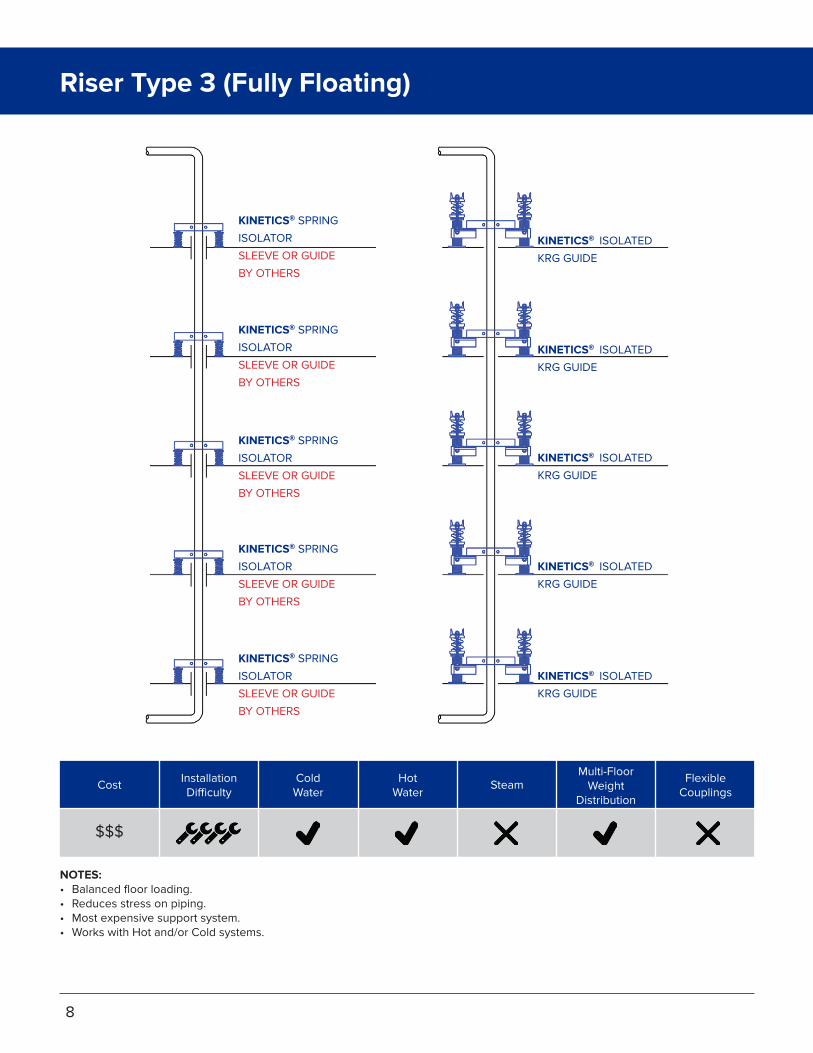
Riser Type 3 (Fully Floating)

NOTES:• Balanced floor loading.• Anchor can be anywhere in the system: top, bottom, mid-story.• Reduces stress on piping.• Anchor “fixes” pipe at it’s location making variations in height due to thermal growth/shrinkage highly predictable.• Simple to install.• Most expensive support system.• Works with Hot and/or Cold systems.
Cost
$$
Installation Difficulty
Multi-Floor Weight
DistributionSteamHot
WaterColdWater
FlexibleCouplings
KINETICS® SPRING
ISOLATOR
SLEEVE OR GUIDE
BY OTHERS
KINETICS® SPRING
ISOLATOR
SLEEVE OR GUIDE
BY OTHERS
KINETICS® SPRING
ISOLATOR
SLEEVE OR GUIDE
BY OTHERS
KINETICS® SPRING
ISOLATOR
SLEEVE OR GUIDE
BY OTHERS
KINETICS®
RESTRAINED/LIMITED
SPRING ISOLATOR
KINETICS®
RESTRAINED/LIMITED
SPRING ISOLATOR
KINETICS® ISOLATED
KRG GUIDE
KINETICS® ISOLATED
KRG GUIDE
KINETICS® ISOLATED
KRG GUIDE
KINETICS® ISOLATED
KRG GUIDE
9
Riser Type 4 (Semi-Floating)

KINETICS® riser supports, anchors, and guides isolate the pipe from the structure to minimize noise and vibration transmission, while also allowing the pipe to expand and contract with minimal change in the support forces.
Non-Isolated Pipe Guide
Isolated Pipe Guide
Pipe Anchor
Spring Isolator
Isolation Hanger
Riser Supports, Anchors, and Guides
10
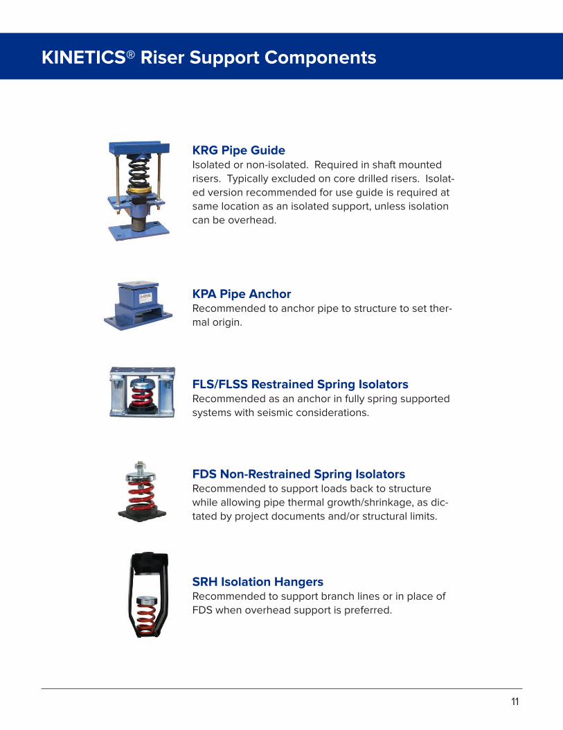
KRG Pipe GuideIsolated or non-isolated. Required in shaft mounted risers. Typically excluded on core drilled risers. Isolat-ed version recommended for use guide is required at same location as an isolated support, unless isolation can be overhead.
KPA Pipe AnchorRecommended to anchor pipe to structure to set ther-mal origin.
FDS Non-Restrained Spring IsolatorsRecommended to support loads back to structure while allowing pipe thermal growth/shrinkage, as dic-tated by project documents and/or structural limits.
FLS/FLSS Restrained Spring IsolatorsRecommended as an anchor in fully spring supported systems with seismic considerations.
SRH Isolation HangersRecommended to support branch lines or in place of FDS when overhead support is preferred.
KINETICS® Riser Support Components
11

Piping/Hanger Selection Data (U.S.)
Piping Weight and Spacing - WaterPipe Size (in.)Pipe ScheduleMax. Spacing (ft.)Insulation (in.)*Wt. per Lin. Ft. (lb.) Pipe Water Insulation TotalWt. @ 10 ft. Spacing (lb.)KNC Hanger Model No. SH/SRH/SFH -1 SH/SRH/SFH -2 SH/SRH/SFH -4Recommended. Rod Size (in.)**Wt. @ 20 ft. Spacing (lb.)KNC Hanger Model No. SH/SRH/SFH -1 SH/SRH/SFH -2 SH/SRH/SFH -4Recommended Rod Size (in.)**Max. Spacing (ft.)Wt. @ Max. Spacing (lb.)KNC Hanger Model No. SH/SRH/SFH -1 SH/SRH/SFH -2 SH/SRH/SFH -4Recommended Rod Size (in.)**
2420321.5
94.9184.0
10.7289.62896
3500-
30001.00
-
----
32-
----
2020301.5
78.8126.1
9.0213.92139
2200250022500.88
-
----
30-
----
1830281.5
82.299.8
8.2190.21902
2200200022500.88
-
----
28-
----
1630271.5
62.779.2
7.3149.21492
1700200016000.75
2984
3500-
30001.00
27-
----
1430251.5
54.759.8
6.5121.01210
1250120012500.75
2419
2465250025000.88
253024
3500-
35001.00
2.54011
1.0
5.82.11.19.090
1251201000.38
-
----
1199
1251201000.38
240101.0
3.71.50.96.161
7070
1000.38
-
----
1061
7070
1000.38
1.540
91.0
2.70.90.84.4
-
-----
----9
40
7070
-0.38
1.2540
71.0
2.30.60.73.6
-
-----
----7
26
3535
-0.38
140
71.0
1.70.40.62.7
-
-----
----7
19
3535
-0.25
840191.5
28.621.7
4.254.5545
6007205000.50
-
----
191036
1000120012500.62
640171.5
19.012.5
3.434.9349
3704655000.50
-
----
17594
6007207500.50
540161.5
14.78.73.0
26.4264
3704652500.50
-
----
16421
5004655000.50
440141.0
10.85.51.5
17.8178
2452202500.50
-
----
14250
3704652500.50
340121.0
7.63.21.3
12.1121
1251201000.38
-
----
12145
2452202500.38
1240231.5
53.748.5
6.0108.21082
1250102510000.62
2163
2200250022500.88
232487
2865250025000.88
1040201.5
40.634.2
5.179.9799
8008507500.62
1598
1700200016000.75
201598
1700200016000.75
Piping Weight and Spacing - SteamPipe Size (in.)Pipe ScheduleInsulation (in.)*Wt. per Ft. (lbs.) Pipe Insulation TotalWt. @ 10 ft. Spacing (lb.)KNC Hanger Model No. SH/SRH/SFH -1 SH/SRH/SFH -2 SH/SRH/SFH -4Recommended Rod Size (in.)**Wt. @ 20 ft. Spacing (lb.)KNC Hanger Model No. SH/SRH/SFH -1 SH/SRH/SFH -2 SH/SRH/SFH -4Recommended Rod Size (in.)**Max. Spacing (ft.)Wt. @ Max. Spacing (lb.)KNC Hanger Model No. SH/SRH/SFH -1 SH/SRH/SFH -2 SH/SRH/SFH -4Recommended Rod Size (in.)**
24202.0
94.9
14.5109.41094
1250120012500.62
218722002500
22501.00
394266
----
20202.0
78.8
12.391.1911
1000102510000.62
182222002000
22500.88
393552
----
18302.0
82.2
11.293.4934
1000102510000.62
186722002000
22500.88
373454
----
16302.0
62.7
10.172.8728
8007207500.62
145617002000
16000.75
352548
2865250027501.00
14302.0
54.7
8.963.6636
6257207500.62
127312502000
16000.75
322036
2200200022501.00
2.5401.55.8
1.87.676
7070
1000.38
---
--
14107
1251201000.38
2401.53.7
1.65.353
7070
1000.38
---
--
1369
7070
1000.38
1.5401.52.7
1.44.141
3535
-0.38
---
--
1250
7070
-0.38
1.25401.52.3
1.33.636
3535
-0.38
---
--
1036
3535
-0.38
1401.51.7
1.22.9
-
-------
--9
26
3535
-0.25
8402.0
28.6
5.934.6346
3704655000.50691625720
7500.62
24829
1000850
10000.62
6402.0
19.0
4.823.8238
2452202500.50477500720
5000.50
21501
5007205000.50
5402.0
14.7
4.218.9189
2452202500.50
---
--
19359
3704655000.50
4401.5
10.8
2.513.3133
1251201000.38
---
--
17227
2452202500.50
3401.57.6
2.19.797
1251201000.38
---
--
15145
2452201000.38
12402.0
53.7
8.261.9619
6257207500.62
123812502000
12500.75
301857
2200200022500.88
10402.0
40.6
7.147.7477
5007205000.50954
10001025
10000.62
261240
1250200012500.75
*Insulation weight based on industry standard insulation.**Rod size recommendation and max. hanger spacing based on MSS SP-69 Approximate Flanged Fitting Weights (lb.)
Pipe Size(In.)
11.52
2.534568
10121416182024
BonnetCheckValve
--
26364680
120155300450675900
1200137117723000
BonnetGateValve
927375066
109140170250470690950
1250165020003100
Elbow8
12182733567897
160260390520725980
13001850
Tee1118243540749111718229040060075093011001850
Flange44579
15192332527093
120140175250
12
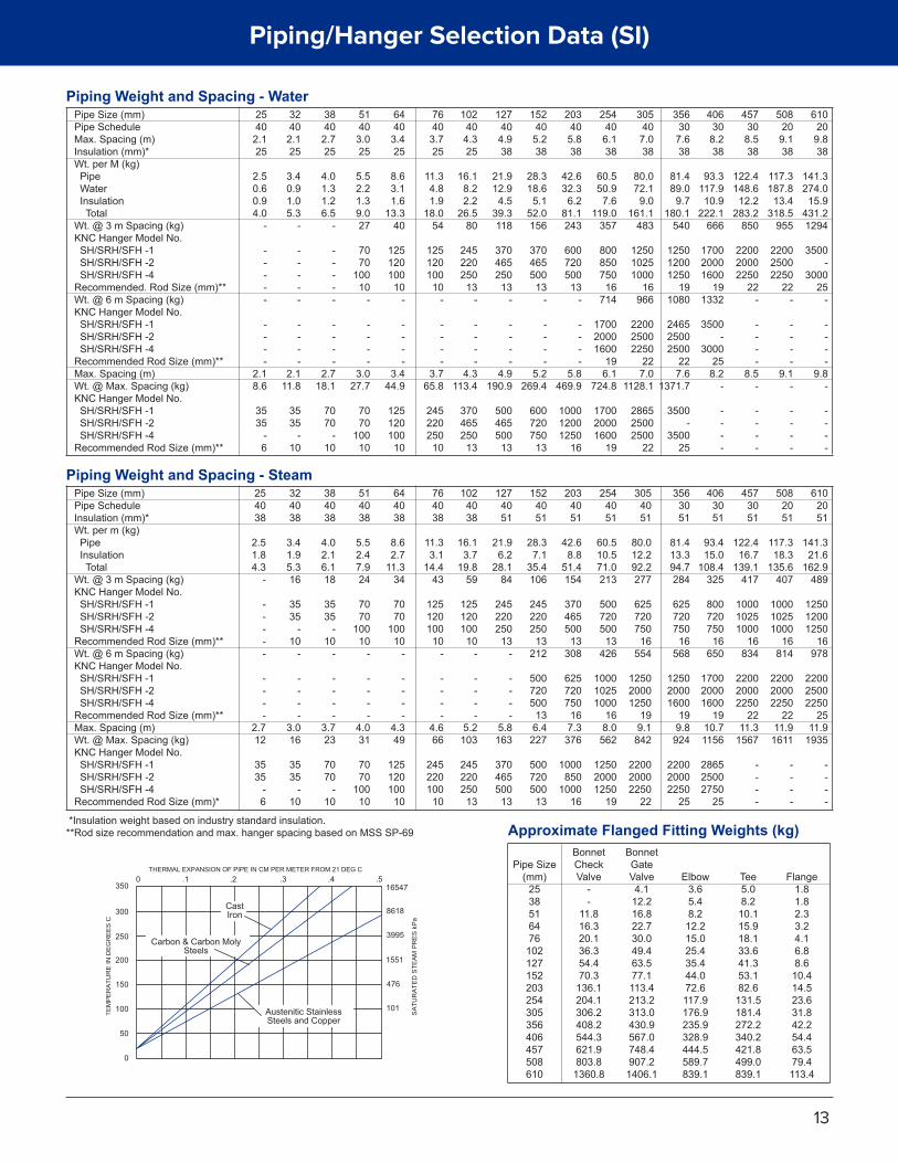
Piping/Hanger Selection Data (SI)
Piping Weight and Spacing - WaterPipe Size (mm)Pipe ScheduleMax. Spacing (m)Insulation (mm)*Wt. per M (kg) Pipe Water Insulation TotalWt. @ 3 m Spacing (kg)KNC Hanger Model No. SH/SRH/SFH -1 SH/SRH/SFH -2 SH/SRH/SFH -4Recommended. Rod Size (mm)**Wt. @ 6 m Spacing (kg)KNC Hanger Model No. SH/SRH/SFH -1 SH/SRH/SFH -2 SH/SRH/SFH -4Recommended Rod Size (mm)**Max. Spacing (m)Wt. @ Max. Spacing (kg)KNC Hanger Model No. SH/SRH/SFH -1 SH/SRH/SFH -2 SH/SRH/SFH -4Recommended Rod Size (mm)**
610209.838
141.3274.0
15.9431.21294
3500-
300025
-
----
9.8-
----
508209.138
117.3187.8
13.4318.5
955
220025002250
22-
----
9.1-
----
457308.538
122.4148.6
12.2283.2
850
220020002250
22-
----
8.5-
----
406308.238
93.3117.910.9
222.1666
170020001600
191332
3500-
3000258.2
-
----
356307.638
81.489.0
9.7180.1
540
125012001250
191080
246525002500
227.6
1371.7
3500-
350025
64403.425
8.63.11.6
13.340
125120100
10-
----
3.444.9
125120100
10
51403.025
5.52.21.39.027
7070
10010
-
----
3.027.7
7070
10010
38402.725
4.01.31.26.5
-
-----
----
2.718.1
7070
-10
32402.125
3.40.91.05.3
-
-----
----
2.111.8
3535
-10
25402.125
2.50.60.94.0
-
-----
----
2.18.6
3535
-6
203405.838
42.632.3
6.281.1243
600720500
13-
----
5.8469.9
100012001250
16
152405.238
28.318.6
5.152.0156
370465500
13-
----
5.2269.4
600720750
13
127404.938
21.912.9
4.539.3118
370465250
13-
----
4.9190.9
500465500
13
102404.325
16.18.22.2
26.580
245220250
13-
----
4.3113.4
370465250
13
76403.725
11.34.81.9
18.054
125120100
10-
----
3.765.8
245220250
10
305407.038
80.072.1
9.0161.1
483
125010251000
16966
220025002250
227.0
1128.1
286525002500
22
254406.138
60.550.9
7.6119.0
357
800850750
16714
170020001600
196.1
724.8
170020001600
19
Piping Weight and Spacing - SteamPipe Size (mm)Pipe ScheduleInsulation (mm)*Wt. per m (kg) Pipe Insulation TotalWt. @ 3 m Spacing (kg)KNC Hanger Model No. SH/SRH/SFH -1 SH/SRH/SFH -2 SH/SRH/SFH -4Recommended Rod Size (mm)**Wt. @ 6 m Spacing (kg)KNC Hanger Model No. SH/SRH/SFH -1 SH/SRH/SFH -2 SH/SRH/SFH -4Recommended Rod Size (mm)**Max. Spacing (m)Wt. @ Max. Spacing (kg)KNC Hanger Model No. SH/SRH/SFH -1 SH/SRH/SFH -2 SH/SRH/SFH -4Recommended Rod Size (mm)*
6102051
141.321.6
162.9489
125012001250
16978
220025002250
2511.9
1935
----
5082051
117.318.3
135.6407
100010251000
16814
220020002250
2211.9
1611
----
4573051
122.416.7
139.1417
100010251000
16834
220020002250
2211.3
1567
----
4063051
93.415.0
108.4325
800720750
16650
170020001600
1910.71156
286525002750
25
3563051
81.413.394.7284
625720750
16568
125020001600
199.8
924
220020002250
25
644038
8.62.7
11.334
7070
10010
-
----
4.349
125120100
10
514038
5.52.47.924
7070
10010
-
----
4.031
7070
10010
384038
4.02.16.118
3535
-10
-
----
3.723
7070
-10
324038
3.41.95.316
3535
-10
-
----
3.016
3535
-10
254038
2.51.84.3
-
-----
----
2.712
3535
-6
2034051
42.68.8
51.4154
370465500
13308
625720750
167.3
376
1000850
100016
1524051
28.37.1
35.4106
245220250
13212
500720500
136.4
227
500720500
13
1274051
21.96.2
28.184
245220250
13-
----
5.8163
370465500
13
1024038
16.13.7
19.859
125120100
10-
----
5.2103
245220250
13
764038
11.33.1
14.443
125120100
10-
----
4.666
245220100
10
3054051
80.012.292.2277
625720750
16554
125020001250
199.1
842
220020002250
22
2544051
60.510.571.0213
500720500
13426
100010251000
168.0
562
125020001250
19
*Insulation weight based on industry standard insulation.**Rod size recommendation and max. hanger spacing based on MSS SP-69 Approximate Flanged Fitting Weights (kg)
Pipe Size(mm)
2538516476
102127152203254305356406457508610
BonnetCheckValve
--
11.816.320.136.354.470.3
136.1204.1306.2408.2544.3621.9803.8
1360.8
BonnetGateValve4.1
12.216.822.730.049.463.577.1113.4213.2313.0430.9567.0748.4907.2
1406.1
Elbow3.65.48.2
12.215.025.435.444.072.6117.9176.9235.9328.9444.5589.7839.1
Tee5.08.2
10.115.918.133.641.353.182.6
131.5181.4272.2340.2421.8499.0839.1
Flange1.81.82.33.24.16.88.6
10.414.523.631.842.254.463.579.4113.4
13
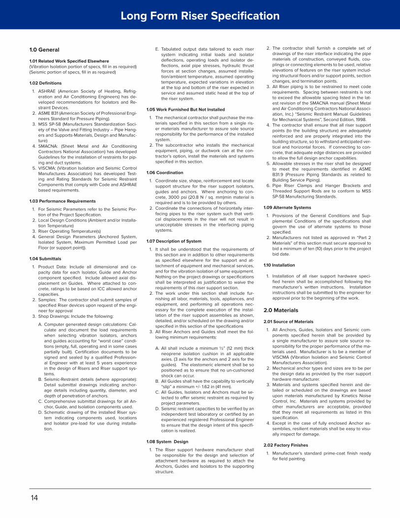
Long Form Riser Specification
1.0 General
1.01 Related Work Specified Elsewhere (Vibration Isolation portion of specs, fill in as required)(Seismic portion of specs, fill in as required)
1.02 Definitions
1. ASHRAE (American Society of Heating, Refrig-eration and Air Conditioning Engineers) has de-veloped recommendations for Isolators and Re-straint Devices.
2. ASME B31 (American Society of Professional Engi-neers Standard for Pressure Piping).
3. MSS SP-58 (Manufacturers Standardization Soci-ety of the Valve and Fitting Industry – Pipe Hang-ers and Supports-Materials, Design and Manufac-ture)
4. SMACNA: (Sheet Metal and Air Conditioning Contractors National Association) has developed Guidelines for the installation of restraints for pip-ing and duct systems.
5. VISCMA: (Vibration Isolation and Seismic Control Manufactures Association) has developed Test-ing and Rating Standards for Seismic Restraint Components that comply with Code and ASHRAE based requirements.
1.03 Performance Requirements
1. For Seismic Parameters refer to the Seismic Por-tion of the Project Specification.
2. Local Design Conditions (Ambient and/or Installa-tion Temperature)
3. Riser Operating Temperature(s)4. General Design Parameters (Anchored System,
Isolated System, Maximum Permitted Load per Floor (or support point)).
1.04 Submittals
1. Product Data: Include all dimensional and ca-pacity data for each Isolator, Guide and Anchor component specified. Include allowed axial dis-placement on Guides. Where attached to con-crete, ratings to be based on ICC allowed anchor capacities.
2. Samples: The contractor shall submit samples of specified Riser devices upon request of the engi-neer for approval
3. Shop Drawings: Include the following:
A. Computer generated design calculations: Cal-culate and document the load requirements when selecting vibration isolators, anchors and guides accounting for “worst case” condi-tions (empty, full, operating and in some cases partially built). Certification documents to be signed and sealed by a qualified Profession-al Engineer with at least 5 years experience in the design of Risers and Riser support sys-tems.
B. Seismic-Restraint details (where appropriate): Detail submittal drawings indicating anchor-age details including quantity, diameter, and depth of penetration of anchors.
C. Comprehensive submittal drawings for all An-chor, Guide, and Isolation components used.
D. Schematic drawing of the installed Riser sys-tem indicating components used, locations and Isolator pre-load for use during installa-tion.
E. Tabulated output data tailored to each riser system indicating initial loads and isolator deflections, operating loads and isolator de-flections, axial pipe stresses, hydraulic thrust forces at section changes, assumed installa-tion/ambient temperature, assumed operating temperature, expected variations in elevation at the top and bottom of the riser expected in service and assumed static head at the top of the riser system.
1.05 Work Furnished But Not Installed
1. The mechanical contractor shall purchase the ma-terials specified in this section from a single ris-er materials manufacturer to assure sole source responsibility for the performance of the installed system.
2. The subcontractor who installs the mechanical equipment, piping, or ductwork can at the con-tractor’s option, install the materials and systems specified in this section.
1.06 Coordination
1. Coordinate size, shape, reinforcement and locate support structure for the riser support isolators, guides and anchors. Where anchoring to con-crete, 3000 psi (20.8 N / sq. mm)min material is required and is to be provided by others.
2. Coordinate the connections of horizontally inter-facing pipes to the riser system such that verti-cal displacements in the riser will not result in unacceptable stresses in the interfacing piping systems.
1.07 Description of System
1. It shall be understood that the requirements of this section are in addition to other requirements as specified elsewhere for the support and at-tachment of equipment and mechanical services, and for the vibration isolation of same equipment. Nothing on the project drawings or specifications shall be interpreted as justification to waive the requirements of this riser support section.
2. The work under this section shall include fur-nishing all labor, materials, tools, appliances, and equipment, and performing all operations nec-essary for the complete execution of the instal-lation of the riser support assemblies as shown, detailed, and/or scheduled on the drawing and/or specified in this section of the specifications
3. All Riser Anchors and Guides shall meet the fol-lowing minimum requirements:
A. All shall include a minimum ½” (12 mm) thick neoprene isolation cushion in all applicable axies. (3 axis for the anchors and 2 axis for the guides). The elastomeric element shall be so positioned as to ensure that no un-cushioned shock can occur.
B. All Guides shall have the capability to vertically “slip” a minimum +/- 1.62 in (41 mm).
C. All Guides, Isolators and Anchors must be se-lected to offer seismic restraint as required by project parameters.
D. Seismic restraint capacities to be verified by an independent test laboratory or certified by an experienced registered Professional Engineer to ensure that the design intent of this specifi-cation is realized.
1.08 System Design
1. The Riser support hardware manufacturer shall be responsible for the design and selection of attachment hardware as required to attach the Anchors, Guides and Isolators to the supporting structure.
2. The contractor shall furnish a complete set of drawings of the riser interface indicating the pipe materials of construction, conveyed fluids, cou-plings or connecting elements to be used, relative elevations of features on the riser system includ-ing structural floors and/or support points, section changes, and termination points.
3. All Riser piping is to be restrained to meet code requirements. Spacing between restraints is not to exceed the allowable spacing listed in the lat-est revision of the SMACNA manual (Sheet Metal and Air Conditioning Contractors National Associ-ation, Inc.) “Seismic Restraint Manual Guidelines for Mechanical Systems”, Second Edition, 1998.
4. The contractor shall ensure that all riser support points (to the building structure) are adequately reinforced and are properly integrated into the building structure, so to withstand anticipated ver-tical and horizontal forces. If connecting to con-crete, that adequate edge distances are provided to allow the full design anchor capabilities.
5. Allowable stresses in the riser shall be designed to meet the requirements identified in ASME B31.9 (Pressure Piping Standards as related to Building Service Piping).
6. Pipe Riser Clamps and Hanger Brackets and Threaded Support Rods are to conform to MSS SP-58 Manufacturing Standards.
1.09 Alternate Systems
1. Provisions of the General Conditions and Sup-plemental Conditions of the specifications shall govern the use of alternate systems to those specified.
2. Manufacturers not listed as approved in “Part 2 Materials” of this section must secure approval to bid a minimum of ten (10) days prior to the project bid date.
1.10 Installation
1. Installation of all riser support hardware speci-fied herein shall be accomplished following the manufacturer’s written instructions. Installation instructions shall be submitted to the engineer for approval prior to the beginning of the work.
2.0 Materials
2.01 Source of Materials
1. All Anchors, Guides, Isolators and Seismic com-ponents specified herein shall be provided by a single manufacturer to assure sole source re-sponsibility for the proper performance of the ma-terials used. Manufacturer is to be a member of VISCMA (Vibration Isolation and Seismic Control Manufacturers Association).
2. Mechanical anchor types and sizes are to be per the design data as provided by the riser support hardware manufacturer.
3. Materials and systems specified herein and de-tailed or scheduled on the drawings are based upon materials manufactured by Kinetics Noise Control, Inc. Materials and systems provided by other manufacturers are acceptable, provided that they meet all requirements as listed in this specification.
4. Except in the case of fully enclosed Anchor as-semblies, resilient materials shall be easy to visu-ally inspect for damage.
2.02 Factory Finishes
1. Manufacturer’s standard prime-coat finish ready for field painting.
14

Long Form Riser Specification
2. Finish: Manufacturer’s standard paint applied to factory-assembled and -tested equipment before shipping.
A. Powder coating on springs and housings. B. All hardware shall be electrogalvanized. Hot-
dip galvanize or powder coat metal housings for exterior use.
C. Enamel or powder coat metal components on isolators for interior use.
D. Color-code or otherwise mark vibration isola-tion devices to indicate capacity range.
2.03 Seismic Snubber Types
Isolator / Snubber Types contained herein are per ASHRAE (American Society of Heating, Refrigerat-ing and Air-Conditioning Engineers, Inc.) Handbook, 2003 HVAC Applications, Chapter 54 “Seismic and Wind Restraint Design”, Pages 12 and 13 or Chapter 47 “Sound and Vibration Control”, Page 44. Anchor and Guide Types that have yet to be classified by ASHRAE.
1. Type A – Chpt 54): Coil Spring Isolator Incor-porated Within A Ductile Iron Or Cast Aluminum Housing
A. Cast iron or aluminum housings are brittle when subjected to shock loading and are therefore not approved for seismic restraint applications, however for low thermal deflec-tion systems, they can be applied in non-seis-mic riser applications.
2. Type B – Chpt 54): Coil Spring Isolator Incorporat-ed Within A Steel Housing
A. Spring isolators shall be seismic control re-strained spring isolators, incorporating a single or multiple coil spring element, having all of the characteristics of free standing coil spring isolators as specified in the vibration isolation portion of this specification. Springs shall be restrained using a housing engineered to limit both lateral and vertical movement of the sup-ported piping during erection, maintenance or an earthquake without degrading the vibration isolation capabilities of the spring during nor-mal operating conditions.
B. Vibration isolators shall incorporate a steel housing and neoprene snubbing grommet sys-tem designed to limit motion to no more than ¼” (6 mm) in any direction and to prevent any direct metal-to-metal contact between the sup-ported member and the fixed restraint hous-ing. The restraining system shall be designed to withstand the design forces in any lateral or vertical direction without yield or failure. Where the capacity of the anchorage hard-ware in concrete is inadequate for the required loading, a steel adapter base plate to allow the addition of more or larger anchors will be fitted to fulfill these requirements. In addition to the primary isolation coil spring, the load path will include a minimum ¼” (6 mm) thick neoprene pad.
C. Spring elements shall be color coded or oth-erwise easily identified. Springs shall have a lateral stiffness greater than 1.2 times the rat-ed vertical stiffness and shall be designed to provide a minimum of 50% overload capacity. Non-welded spring elements shall be epoxy powder coated and shall have a minimum of a 1000 hour rating when tested in accordance with ASTM B-117.
D. To facilitate servicing, the isolator will be de-signed in such a way that the coil spring ele-ment can be removed without the requirement to lift or otherwise disturb the supported riser system.
E. Spring isolators shall be Model FHS as manu-factured by Kinetics Noise Control, or by other manufacturers who can meet the requirements as listed in sections 1.04 through 1.09 inclusive, and sections 2.01, 2.02 and 2.03 (2).
3. Type C – Chpt 54): Coil Spring Isolator Incorpo-rated Within A Steel Housing
A. Spring isolators shall be seismic control re-strained spring isolators, incorporating one or more coil spring elements, having all of the characteristics of free standing coil spring iso-lators per the vibration isolation section of this specification. Isolators shall consist of one or more laterally stable steel coil springs assem-bled into fabricated welded steel housings designed to limit movement of the supported riser in all directions.
B. Housing assembly shall be made of fabricated steel members and shall consist of a top load plate complete with adjusting and leveling bolts, adjustable vertical restraints, isolation washers, and a bottom load plate with internal non-skid isolation pads and holes for anchor-ing the housing to the supporting structure. Housing shall be hot dipped galvanized for outdoor corrosion resistance. Housing shall be designed to provide a constant free and operating height within 1/8” (3 mm).
C. The isolator housing shall be designed to withstand the project design forces in all direc-tions.
D. Coil spring elements shall be selected to provide static deflections as shown on the vibration isolation schedule or as indicated or required in the project documents. Spring ele-ments shall be color coded or otherwise easily identified. Springs shall have a lateral stiffness greater than 1.2 times the rated vertical stiff-ness and shall be designed to provide a min-imum of 50% overload capacity. Non-welded spring elements shall be epoxy powder coated and shall have a minimum of a 1000 hour rating when tested in accordance with ASTM B-117.
E. Spring isolators shall be Model FLSS as manu-factured by Kinetics Noise Control, or by other manufacturers who can meet the requirements as listed in sections 1.04 through 1.09 inclusive, and sections 2.01, 2.02 and 2.03 (5)
4. Type D – Chpt 54): Coil Spring Isolator Incorpo-rated With Integral Seismic Restraint
A. Spring isolators shall be single or multiple coil spring elements which have all of the charac-teristics of free standing coil spring isolators as specified in the vibration isolation portion of this specification, incorporating lateral and ver-tically restrained seismic housing assemblies. Spring elements shall be readily replaceable without the need to lift or remove the support-ed riser system.
B. Restraint housing shall be sized to meet or exceed the force requirements of the applica-tion and shall have the capability of accepting coil springs of various sizes, capacities, and deflections as required to meet the required isolation criteria. All spring forces shall be contained within the coil / housing assembly, and the restraint anchoring hardware shall not be exposed to spring generated forces under conditions of no seismic force. Spring element leveling adjustment shall be accessible from above and suitable for use with a conventional pneumatic or electric impact wrench.
C. Restraint element shall incorporate a steel housing with elastomeric elements at all dy-namic contact points. Elastomeric elements shall be replaceable. Restraint shall allow ¼” (6 mm) free motion in any direction from the neutral position. Restraint shall have an over-turning factor (ratio of effective lateral snubber height to short axis anchor spacing) of 0.33 or less to ensure optimum anchorage capacity.
D. Spring isolators shall be Model FMS as manu-factured by Kinetics Noise Control, or by other manufacturers who can meet the requirements as listed in sections 1.04 through 1.09 inclusive, and sections 2.01, 2.02 and 2.03 (4).
5. Type 3 – Chpt 47): Free Standing Coil Spring Iso-lator
A. Spring isolators shall be free-standing spring isolators, incorporating one or more coil spring elements, having all of the characteristics of free standing coil spring isolators per the vi-bration isolation section of this specification. Isolators shall consist of one or more lateral-ly stable steel coil springs with an adjustable leveling screw and neoprene faced baseplate suitable for riser applications.
B. Coil spring elements shall be selected to provide static deflections as shown on the vibration isolation schedule or as indicated or required in the project documents. Spring ele-ments shall be color coded or otherwise easily identified. Springs shall have a lateral stiffness greater than 1.2 times the rated vertical stiff-ness and shall be designed to provide a min-imum of 50% overload capacity. Non-welded spring elements shall be epoxy powder coated and shall have a minimum of a 1000 hour rating when tested in accordance with ASTM B-117.
C. Spring isolators shall be Model FDS as manu-factured by Kinetics Noise Control, or by other manufacturers who can meet the requirements as listed in sections 1.04 through 1.09 inclusive, and sections 2.01, 2.02 and 2.03 (3)
6. Type 4 – Chpt 47): Free Standing Restrained Coil Spring Isolator
A. Spring isolators shall be free-standing Re-strained spring isolators, incorporating one or more coil spring elements, having all of the characteristics of free standing coil spring isolators per the vibration isolation section of this specification. Isolators shall consist of one or more laterally stable steel coil springs with an adjustable leveling screw and neoprene faced baseplate suitable for riser applications. Isolators shall further include a mechanism to internally pre-load the spring coil, capturing all pre-load forces within the isolator itself.
B. Coil spring elements shall be selected to provide static deflections as shown on the vibration isolation schedule or as indicated or required in the project documents. Spring ele-ments shall be color coded or otherwise easily identified. Springs shall have a lateral stiffness greater than 1.2 times the rated vertical stiff-ness and shall be designed to provide a min-imum of 50% overload capacity. Non-welded spring elements shall be epoxy powder coated and shall have a minimum of a 1000 hour rating when tested in accordance with ASTM B-117.
C. Spring isolators shall be Model FRS as manu-factured by Kinetics Noise Control, or by other manufacturers who can meet the requirements as listed in sections 1.04 through 1.09 inclusive, and sections 2.01, 2.02 and 2.03 (6)
15
Long Form Riser Specification
7. Type E – Chpt 54): All Direction Neoprene Iso-lator
A. Vibration Isolators shall be neoprene, molded from oil resistant compounds, designed to op-erate within the strain limits of the isolator so to provide the maximum isolation and longest life expectancy possible using neoprene com-pounds. Isolators shall include encapsulated cast-in-place top steel load transfer plate for bolting to Riser and a steel base plate with an-chor holes for bolting to the supporting struc-ture.
B. Isolator shall be capable of withstanding the design loads in all directions with no met-al-to-metal contact.
C. Isolator shall have minimum operating static deflections as shown on the project Vibration Isolation Schedule or as otherwise indicated in the project documents and shall not exceed published load capacities.
D. Neoprene isolators shall be Model RQ as man-ufactured by Kinetics Noise Control, or by oth-er manufacturers who can meet the require-ments as listed in sections 1.04 through 1.09 inclusive, and sections 2.01, 2.02 and 2.03 (7)
8. Riser Anchor): All Direction 3-Axis Riser Anchor Assembly
A. Risers shall be restrained against excessive movement during service by the use of 3-axis resilient anchors designed to withstand the required installation and operating forces. Anchors are intended to be used in sets of two (2), and be oriented to effectively restrain the riser in all three directions, with particular emphasis on large and variable vertical loads that would be imparted by changes in the riser weight.
B. Anchors shall be of steel construction and shall be attached to the riser with either a heavy-du-ty riser clamp or a welded support bracket in a manner consistent with anticipated design loads. Snubbers shall limit lateral and vertical riser movement at each anchor location to a maximum of ¼” (6 mm) in any direction.
C. Anchors shall include a minimum 1/2” (13 mm) thick resilient neoprene pad to cushion any impact and to avoid any potential for met-al-to-metal contact. Maximum neoprene bear-ing pressure shall not exceed 1500 pounds / sq. inch (10.4 N / sq. mm). Anchors shall be capable of withstanding an externally applied force of up to their rated capacity in any direc-tion.
D. Riser Anchors shall be Model KPA as manu-factured by Kinetics Noise Control, or by other manufacturers who can meet the requirements as listed in sections 1.04 through 1.09 inclusive, and 2.01, 2.02 and 2.03 (8)
9. Riser Guide): Horizontal motion limiting Riser Guide Assembly
A. Risers shall be restrained against excessive lateral movement during service by the use of 2-axis resilient guides designed to withstand the required installation and operating forces. Guides are intended to be used in sets of two (2), and be oriented to effectively restrain the riser in all horizontal directions, but to allow free motion within their operating range in the vertical axis.
B. Guides shall be of steel construction and shall be attached to the riser with either a heavy-du-ty riser clamp or a welded support bracket in a manner consistent with anticipated design loads. Guides shall limit lateral riser movement at each Guide location to a maximum of ¼” (6 mm) in any direction.
C. Anchors shall include a minimum 1/2” (13 mm) thick resilient neoprene pad to cushion any impact and to avoid any potential for met-al-to-metal contact. Maximum neoprene bear-ing pressure shall not exceed 1500 pounds / sq. inch (10.4 N / sq. mm). Anchors shall be capable of withstanding an externally applied lateral force of up to their rated capacity in any direction.
D. Riser Guides shall be Model KPG as manufac-tured by Kinetics Noise Control, or by other manufacturers who can meet the requirements as listed in sections 1.04 through 1.09 inclusive, and 2.01, 2.02 and 2.03 (9)
3.0 Execution
3.01 Installation
1. Installation of all Riser support components and materials specified in this section shall be accom-plished as per the manufacturer’s written instruc-tions.
2. Upon completion of installation of all Riser hard-ware and before filling and start up of riser sys-tem, all debris shall be cleaned from locations where it could restrict the free expansion and contraction of the piping.
3. No rigid connections between the Riser and the building structure shall be made which degrades the seismic restraint system herein specified.
4. All isolators are to be adjusted to the preset di-mensions as provided by Kinetics Noise Control prior to filling. After the piping systems have been filled, equipment is operational and the riser is at it’s normal operating temperature, all restrained spring isolators are to be inspected and where/if they remain preloaded, the preload nuts are be backed off the minimum amount to ensure that contact in the preload screw no longer exists.
5. Torque anchor bolts according to Kinetics Noise Control provided written recommendations to re-sist system forces.
3.02 Execution
1. Where installation anchor bolts to concrete:
A. Install adequate reinforcement in the concrete structural element to ensure its integrity if sub-jected to appropriate lateral or vertical loads.
B. Install wedge type anchors into floor. If thick-ness is inadequate for full anchor embedment, install bolts that extend through the floor slab and secure them with nuts fitted to the under-side of the structural concrete floor.
C. Place and secure anchorage devices. Use setting drawings, templates, diagrams, instruc-tions, and directions furnished with items to be embedded.
D. Install anchor bolts to elevations required for proper attachment to supported componentry.
E. Install anchor bolts according to Kinetics Noise Controls written instructions.
3.03 Inspection
1. The contractor shall notify the local representa-tive of the Riser materials manufacturer prior to installing any riser hardware. The contractor shall seek the representative’s guidance in any installa-tion procedures with which he is unfamiliar.
2. Upon completion of the installation of all riser sup-port devices herein specified, the local represen-tative of the riser hardware manufacturer shall, at the contractors request, inspect the completed system and report in writing any installation er-rors, improperly selected devices, or other fault in the system which could affect the performance of the system.
3. The installing contractor shall submit a report upon request to the building architect and/or en-gineer, including the manufacturer’s representa-tive’s final report, indicating that all riser support material has been properly installed.
End of Section
RISER │ 05/18Kinetics Noise Control, Inc. is continually upgrading the quality of our products. We reserve the right to make changes to this and all products without notice.
MADE IN USA