pipe flow - pdhonline.com pipe flow the flow velocity will be such that the fluid particles will not...
TRANSCRIPT

PDHonline Course M204 (3 PDH)
Pipe Flow
2012
Instructor: Gary D. Beckfeld, P.E.
PDH Online | PDH Center5272 Meadow Estates Drive
Fairfax, VA 22030-6658Phone & Fax: 703-988-0088
www.PDHonline.orgwww.PDHcenter.com
An Approved Continuing Education Provider
www.PDHcenter.com PDH Course M204 www.PDHonline.org
Pipe Flow Gary D. Beckfeld, M.S.E., P.E.
COURSE CONTENT
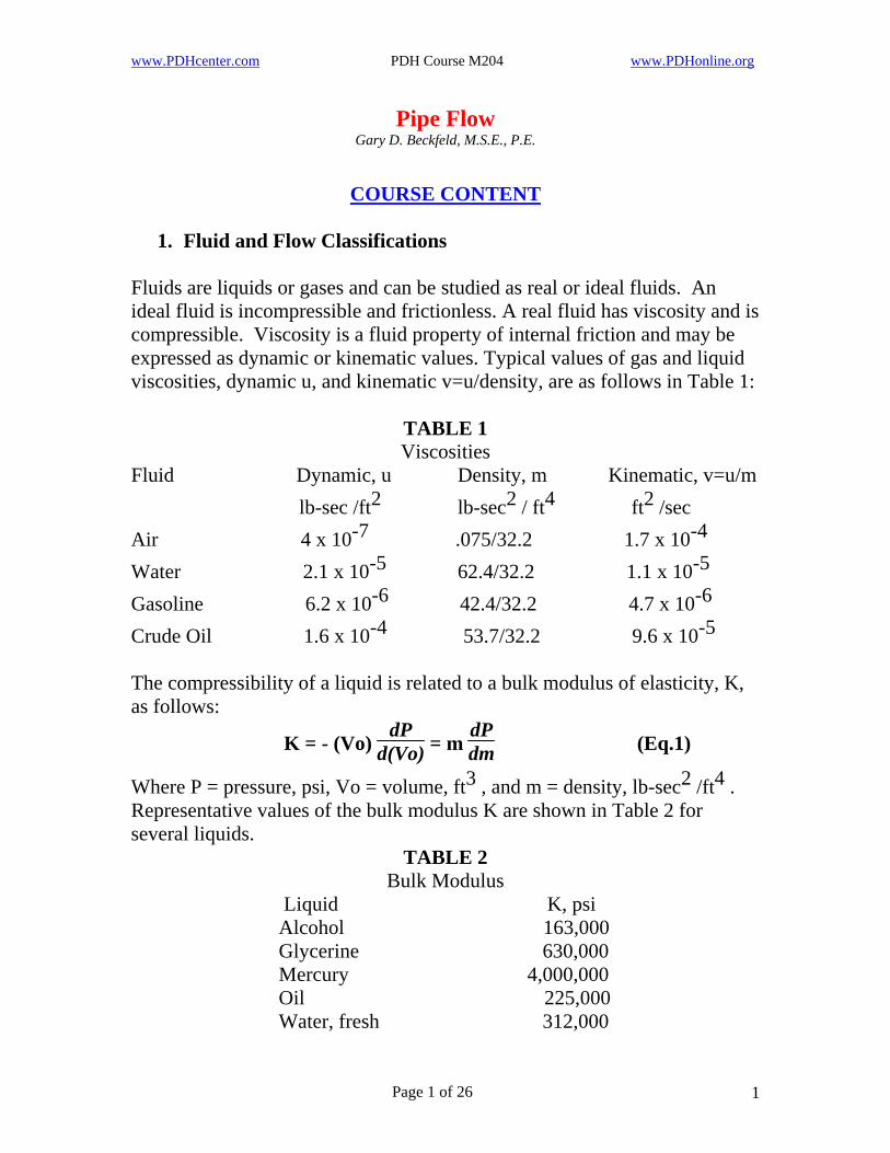
1. Fluid and Flow Classifications Fluids are liquids or gases and can be studied as real or ideal fluids. An ideal fluid is incompressible and frictionless. A real fluid has viscosity and is compressible. Viscosity is a fluid property of internal friction and may be expressed as dynamic or kinematic values. Typical values of gas and liquid viscosities, dynamic u, and kinematic v=u/density, are as follows in Table 1:
TABLE 1 Viscosities
Fluid Dynamic, u Density, m Kinematic, v=u/m lb-sec /ft2 lb-sec2 / ft4 ft2 /sec Air 4 x 10⁻⁷ .075/32.2 1.7 x 10⁻⁴ Water 2.1 x 10⁻⁵ 62.4/32.2 1.1 x 10⁻⁵ Gasoline 6.2 x 10⁻⁶ 42.4/32.2 4.7 x 10⁻⁶ Crude Oil 1.6 x 10⁻⁴ 53.7/32.2 9.6 x 10⁻⁵ The compressibility of a liquid is related to a bulk modulus of elasticity, K, as follows:
K = - (Vo) dP
d(Vo) = m dPdm (Eq.1)
Where P = pressure, psi, Vo = volume, ft3 , and m = density, lb-sec2 /ft4 . Representative values of the bulk modulus K are shown in Table 2 for several liquids.
TABLE 2 Bulk Modulus
Liquid K, psi Alcohol 163,000 Glycerine 630,000 Mercury 4,000,000 Oil 225,000 Water, fresh 312,000
Page 1 of 26 1
www.PDHcenter.com PDH Course M204 www.PDHonline.org
Equation 1 may be rearranged to give the change in density with change in pressure as
dmm =
dPK (Eq.2)
The compressibility of water is illustrated by considering a pressure change of 100 atmospheres (1470 psi) and finding the percent change in density.
dmm = 100
1470312000 = 0.47 %
This indicates that the compressibility of water is negligible at the pressure changes of much less than 100 atmospheres expected in most cases of fluid flow. For comparison, the compressibility of gas for isothermal flow is found from Boyle’s law, (P/m) = constant. Differentiating gives
1m dP - P
dmm2 = 0 or
dmm =
dPP (Eq.3)
For a gas at atmospheric pressure (14.7 psi) and a pressure change of 1/10 atmosphere (1.47 psi), the percent change in density is
dmm = 100
1.4714.7 = 10 % (isothermal gas)
For adiabatic flow, the relation (P/mk ) = constant holds and differentiating gives
1
mk dP – kP dm
mk+1 = 0 or dmm =
dPkP (Eq.4)
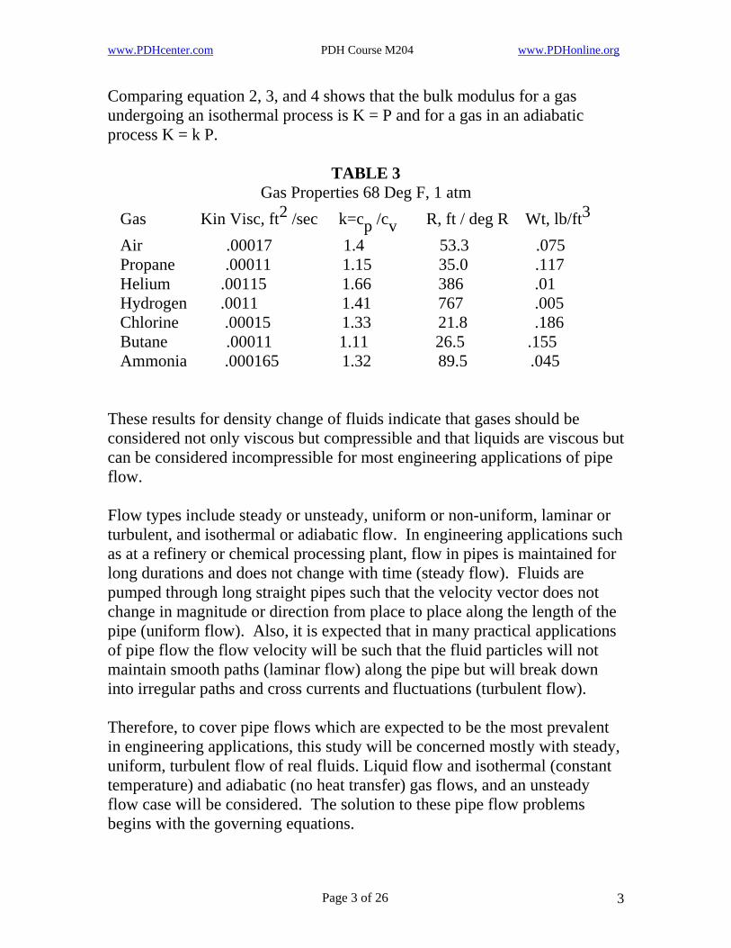
Where k = cp /cv , ratio of constant pressure specific heat to constant volume specific heat. For air k=1.4. Other k values are in Table 3. For air at 14.7 psi and a 1/10 atmosphere pressure change, the percent density change is
dmm = 100
1.471.4(14.7) = 7.1 % (adiabatic gas)
Page 2 of 26 2
www.PDHcenter.com PDH Course M204 www.PDHonline.org
Comparing equation 2, 3, and 4 shows that the bulk modulus for a gas undergoing an isothermal process is K = P and for a gas in an adiabatic process K = k P.
TABLE 3 Gas Properties 68 Deg F, 1 atm
2 Gas Kin Visc, ft /sec k=cp /cv R, ft / deg R Wt, lb/ft3 Air .00017 1.4 53.3 .075 Propane .00011 1.15 35.0 .117 Helium .00115 1.66 386 .01 Hydrogen .0011 1.41 767 .005 Chlorine .00015 1.33 21.8 .186 Butane .00011 1.11 26.5 .155 Ammonia .000165 1.32 89.5 .045 These results for density change of fluids indicate that gases should be considered not only viscous but compressible and that liquids are viscous but can be considered incompressible for most engineering applications of pipe flow. Flow types include steady or unsteady, uniform or non-uniform, laminar or turbulent, and isothermal or adiabatic flow. In engineering applications such as at a refinery or chemical processing plant, flow in pipes is maintained for long durations and does not change with time (steady flow). Fluids are pumped through long straight pipes such that the velocity vector does not change in magnitude or direction from place to place along the length of the pipe (uniform flow). Also, it is expected that in many practical applications of pipe flow the flow velocity will be such that the fluid particles will not maintain smooth paths (laminar flow) along the pipe but will break down into irregular paths and cross currents and fluctuations (turbulent flow). Therefore, to cover pipe flows which are expected to be the most prevalent in engineering applications, this study will be concerned mostly with steady, uniform, turbulent flow of real fluids. Liquid flow and isothermal (constant temperature) and adiabatic (no heat transfer) gas flows, and an unsteady flow case will be considered. The solution to these pipe flow problems begins with the governing equations.
Page 3 of 26 3
www.PDHcenter.com PDH Course M204 www.PDHonline.org
2. Governing Equations The descriptive relations in pipe flow include the continuity equation, the momentum equation, and the energy equation. Additional useful relations are velocity distribution equations, the Reynolds number, the Mach number, the speed of sound, gas laws and the equation of state. Referring to Figure 1, for steady state conditions, these equations are as follows: Continuity Equation (Conservation of mass) Compressible flow m1 A1 V1 = m2 A2 V2 (Eq.5) Incompressible flow Q = A1 V1 = A2 V2 (Eq.6) Where m1 , m2 = mass density at the pipe entrance and exit respectively
= slug/ft3 2 = (lb-sec )/ft4 m1 = m2 for incompressible flow
2 A1 , A2 = pipe entrance and exit cross section area, ft V1 , V2 = pipe entrance and exit average flow velocity, ft/sec
3 /sec Q = flow rate, ft Momentum Equation (Conservation of momentum) (vector equations)
22
12Compressible flow F = m2 A2 V - m1 A1 V (Eq.7)
Incompressible flow F = m Q ( V2 - V1 ) (Eq.8) Where F = sum of forces exerted on the pipe system by the fluid flow, lb m = m1 = m2 for incompressible flow The velocity V in equations 7 and 8 is the average velocity over the pipe cross section. As shown in Figure 2, the laminar and turbulent velocities vary over the cross section. To account for this variation from the average, the right side of equations 7 and 8 must be multiplied by a momentum correction factor beta. This factor is approximately as follows: Laminar flow beta = 1.33 (Eq.9) Turbulent flow beta = 1.04 (Eq.10)
Page 4 of 26 4

www.PDHcenter.com PDH Course M204 www.PDHonline.org
Energy Equation (Conservation of energy) Incompressible flow
V12
2gp1mg
V22g
2 + + z1 + H =
p2mg + + z2 + HL (Eq.11)
Compressible isothermal (constant temperature) flow
V12
2gV22g
2p1m1g + z1 + H =
p2m2g loge p1 + loge p2 + + z2 + HL (Eq.12)
Compressible adiabatic (no heat transfer) flow
( k
k-1 )p1
m1g + V1
2
2gV22g
2 + z1 + H = (
kk-1 )
p2m2g + + z2 + HL (Eq.13)
where p1 , p2 = pipe entrance and exit absolute static pressure, lb/ft2 z1 , z2 = entrance and exit height from a datum at the pump centerline, above positive, below negative, ft H = head (designating energy) supplied by the pump or fan, ft HL = energy or head loss due to friction, entrance, and fittings, ft
2 g = 32.2 ft/sec loge = ln = natural logarithm and m, V, k are as previously defined.
2 The velocity head or kinetic energy term V /2g is based on an average or uniform velocity over the pipe cross section. Both the laminar and turbulent velocities vary from this uniform distribution as shown in Figure 2. To account for this variation, the kinetic energy terms in equations 11, 12, and 13, should be multiplied by a correction factor, alpha, with approximate values as follows: Laminar flow alpha = 2.0 (Eq.14) Turbulent flow alpha = 1.1 (Eq.15)
Page 5 of 26 5

www.PDHcenter.com PDH Course M204 www.PDHonline.org
PUMP
FIGURE 1 PIPE DIAGRAM
STATION 1ENTRANCE
Z 1
1P
P
2Z
STATION 2EXIT
2
Velocity Distributions (see Figure 2)
r2
ro2Laminar flow V1 (r) = V1max ( 1- ) (Eq.16)
V1max = 2 V1 = 2m2A2V2
m1A1 (Eq.17)
Turbulent flow V1 (r) = V1max (1 - rro
)1/7 (Eq.18)
V1max = 12098 V1 = (
12098 )
m2A2V2m1A1
(Eq.19)
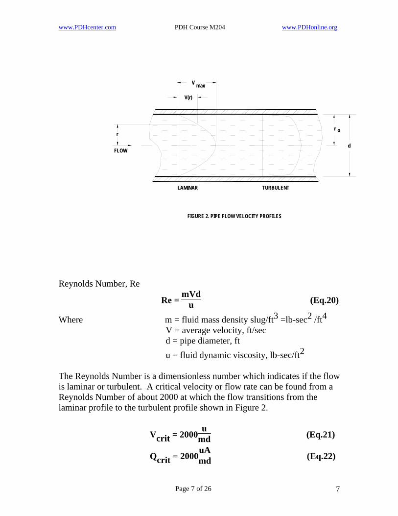
Where ro = pipe radius, r = radial distance from the pipe centerline V1 , V2 = average velocities The velocity profiles for Equations 16 and 18 are illustrated in Figure 2.
Page 6 of 26 6
www.PDHcenter.com PDH Course M204 www.PDHonline.org
FIGURE 2. PIPE FLOW VELOCITY PROFILES
LAMINAR
r
FLOW
V(r)
V max
TURBULENT
o
d
r
Reynolds Number, Re
Re = mVd
u (Eq.20)
Where m = fluid mass density slug/ft3 2 =lb-sec /ft4 V = average velocity, ft/sec d = pipe diameter, ft
2 u = fluid dynamic viscosity, lb-sec/ft The Reynolds Number is a dimensionless number which indicates if the flow is laminar or turbulent. A critical velocity or flow rate can be found from a Reynolds Number of about 2000 at which the flow transitions from the laminar profile to the turbulent profile shown in Figure 2.
Vcrit = 2000u
md (Eq.21)
Qcrit = 2000uAmd (Eq.22)
Page 7 of 26 7
www.PDHcenter.com PDH Course M204 www.PDHonline.org
Speed of sound, a
a = ( Km
1/2 ) (Eq.23)
For water, K = 312,000 lb/in2 (Table 2), and m = 62.4 lb/ft3 /32.2 ft/sec2 (Table 1), so the speed of sound in water is
312000 lb/in2(144 in2/ft2)1.94 lb-sec2/ft4
1/2 a = ( )
a = 4812 ft/sec (water speed of sound) Equation 23 is for liquids or gases. But a sound wave passing through gas is essentially an adiabatic (no heat transfer) process so the bulk modulus in equation 23 is K = kp (see Eq. 2 and 4). From the gas law, p=mgRT, so for gases equation 23 becomes a = (kgRT)1/2 (Eq.24) where R = gas constant, ft/deg Rankine (Table 3) T = temperature, deg Rankine = deg Fahrenheit + 460 For air, k = 1.4, and R = 53.3 ft/ deg Rankine, so the speed of sound in air is
2 1/2 a = (1.4 (32.2 ft/sec )(53.3 ft/deg Rankine)T) 1/2 (Eq.25) a = 49(T)
For air at 78 deg Fahrenheit, the speed of sound is
1/2 a = 49 (78 + 460) a = 1137 ft/sec (air speed of sound) Mach number, M
M = Va (Eq.26)
The Mach number is an indicator of the importance of compressibility.
Page 8 of 26 8
www.PDHcenter.com PDH Course M204 www.PDHonline.org
The effect of compressibility is seen for the case of gas flow in a pipe where the flow is stopped at a point adiabatically (no heat transfer) such that the velocity V2 = 0 in the energy equations. For no pump power added H = 0, no friction losses, HL = 0, and a horizontal pipe, z1 = z2 . Considering the flow as incompressible, the incompressible energy equation (11) gives
mV12
2 p2 = p1 + (Eq.27)
The compressible adiabatic energy equation (13) can be put in the form
m1V12
2 p2 = p1 + [1 + 14 +
(2-k)241
2 M M14 + …] (Eq.28)
Comparing equations 27 and 28 shows the effect of compressibility is to increase the pressure p2 but for a Mach number less than about M = 0.2, this increase can be neglected and incompressible equations can be used. For Mach number greater then M = 0.2, the compressible relations should be used for correct answers. Eq.28 applies only for M<1.0. Gas Laws
Isothermal (Boyle’s) law pm = constant (Eq.29)
pmkAdiabatic law = constant (Eq.30)
Charles’ law 1
mT = constant (Eq.31)
Equation of state (general gas law) p = mgRT (Eq.32) where R is the gas constant given in Table 3. R may also be found from R = 1544/w (Eq.33) Where w is the molecular weight of the gas. For example the molecular weight of steam, H2 O, is w = 2 + 16 = 18, and Rsteam = 1544/18 = 85.8 (Eq.34)
Page 9 of 26 9
www.PDHcenter.com PDH Course M204 www.PDHonline.org
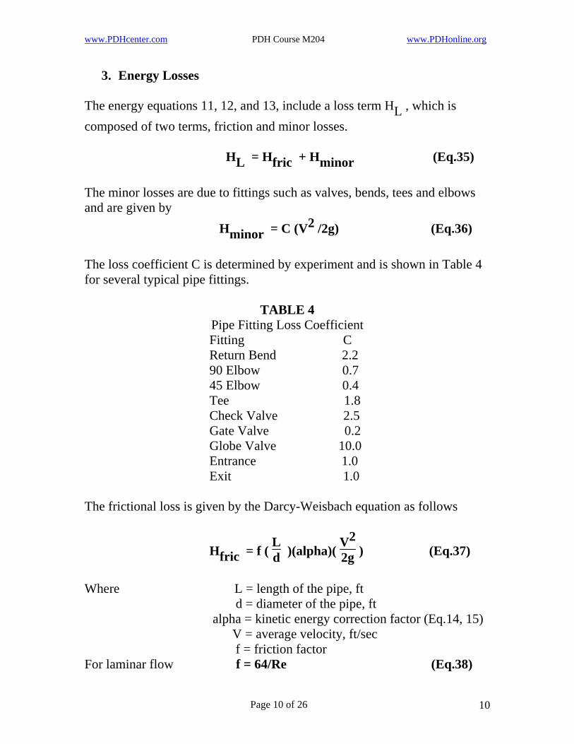
3. Energy Losses The energy equations 11, 12, and 13, include a loss term HL , which is composed of two terms, friction and minor losses. HL = Hfric + Hminor (Eq.35) The minor losses are due to fittings such as valves, bends, tees and elbows and are given by Hminor = C (V2 /2g) (Eq.36) The loss coefficient C is determined by experiment and is shown in Table 4 for several typical pipe fittings.
TABLE 4 Pipe Fitting Loss Coefficient
Fitting C Return Bend 2.2 90 Elbow 0.7 45 Elbow 0.4 Tee 1.8 Check Valve 2.5 Gate Valve 0.2 Globe Valve 10.0 Entrance 1.0 Exit 1.0 The frictional loss is given by the Darcy-Weisbach equation as follows
Hfric = f ( Ld )(alpha)(
V22g ) (Eq.37)
Where L = length of the pipe, ft d = diameter of the pipe, ft alpha = kinetic energy correction factor (Eq.14, 15) V = average velocity, ft/sec f = friction factor For laminar flow f = 64/Re (Eq.38)
Page 10 of 26 10
www.PDHcenter.com PDH Course M204 www.PDHonline.org
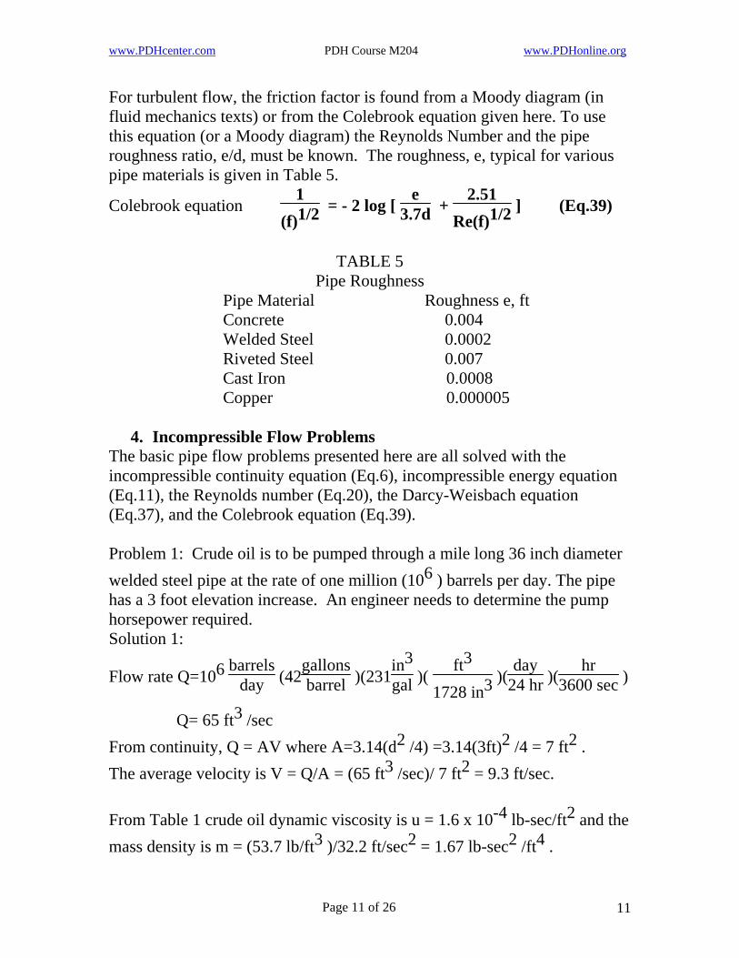
For turbulent flow, the friction factor is found from a Moody diagram (in fluid mechanics texts) or from the Colebrook equation given here. To use this equation (or a Moody diagram) the Reynolds Number and the pipe roughness ratio, e/d, must be known. The roughness, e, typical for various pipe materials is given in Table 5.
1(f)1/2
2.51Re(f)1/2 = - 2 log [
e3.7dColebrook equation + ] (Eq.39)
TABLE 5
Pipe Roughness Pipe Material Roughness e, ft Concrete 0.004 Welded Steel 0.0002 Riveted Steel 0.007 Cast Iron 0.0008 Copper 0.000005
4. Incompressible Flow Problems The basic pipe flow problems presented here are all solved with the incompressible continuity equation (Eq.6), incompressible energy equation (Eq.11), the Reynolds number (Eq.20), the Darcy-Weisbach equation (Eq.37), and the Colebrook equation (Eq.39). Problem 1: Crude oil is to be pumped through a mile long 36 inch diameter welded steel pipe at the rate of one million (106 ) barrels per day. The pipe has a 3 foot elevation increase. An engineer needs to determine the pump horsepower required. Solution 1:
Flow rate Q=106 barrels
day (42gallonsbarrel )(231
in3gal )(
ft3
1728 in3 )(day
24 hr )(hr
3600 sec )
Q= 65 ft3 /sec From continuity, Q = AV where A=3.14(d2 /4) =3.14(3ft)2 /4 = 7 ft2 . The average velocity is V = Q/A = (65 ft3 /sec)/ 7 ft2 = 9.3 ft/sec. From Table 1 crude oil dynamic viscosity is u = 1.6 x 10⁻⁴ lb-sec/ft2 and the mass density is m = (53.7 lb/ft3 )/32.2 ft/sec2 = 1.67 lb-sec2 /ft4 .
Page 11 of 26 11

www.PDHcenter.com PDH Course M204 www.PDHonline.org
Solution 1 continued: From Eq.20 the Reynolds number is
Re = mVd
u = (1.67lb-sec2 /ft4 )(9.3ft/sec)(3ft)/(0.00016lb-sec/ft2 )
Re = 291,206 (turbulent flow for Re>2000) For this turbulent flow, the energy correction factor, alpha, to be used in the Darcy-Weisbach equation (37) is given by Eq.15, alpha=1.1. Also, the pipe roughness, e, for welded steel pipe is given in Table 5 as e = 0.0002 ft. The relative roughness is e/d = 0.0002/3 = 0.000067 Substitute Re = 291,206 and e/d = 0.000067 in Eq.39. By iteration find a friction factor of f = 0.015. Then the frictional head loss from Eq. 37 is
Hfric = 0.015 (5280
3 )( 1.1)[(9.3)2
2 (32.2) ] = 39 ft
Other losses come from the entrance and exit of the pipe. Table 4 gives the loss coefficient, C, for both entrance and exit as C = 1.0. From Eq.36
Hminor = 1.0 [(9.3)22(32.2)
(9.3)22(32.2) ] + 1.0 [ ] = 2.7 ft
Since the pipe is of constant area, the continuity equation (6) gives constant velocity. Neglecting pressure change due to elevation change, the energy equation (11) gives H = Hfric + Hminor + (z2 - z1 ) = 39 + 2.7 + 3 H = 44.7 ft = 44.7 ft-lb/lb meaning that the flow loses 44.7 ft-lb of energy for every lb of fluid flowing and that energy must be input by the pump. The flow rate in pounds is given by
3 Q m g = (65 ft /sec)(53.7 lb/ft3 ) = 3490 lb/sec The power required is given by P =m g Q H (Eq.40) So P = 3490 lb/sec (44.7 ft) = 156,000 ft-lb/sec The horsepower required is HP = P/550 = 156,000/550 = 284 hp Final answer
Page 12 of 26 12
www.PDHcenter.com PDH Course M204 www.PDHonline.org
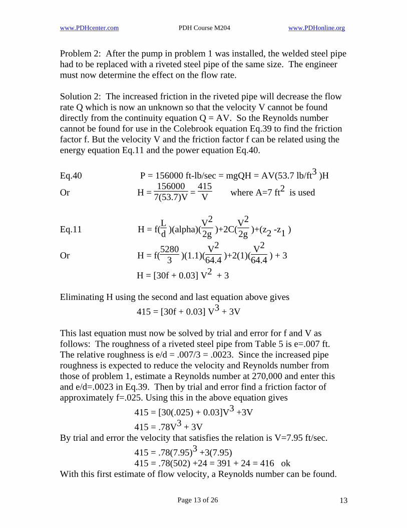
Problem 2: After the pump in problem 1 was installed, the welded steel pipe had to be replaced with a riveted steel pipe of the same size. The engineer must now determine the effect on the flow rate. Solution 2: The increased friction in the riveted pipe will decrease the flow rate Q which is now an unknown so that the velocity V cannot be found directly from the continuity equation Q = AV. So the Reynolds number cannot be found for use in the Colebrook equation Eq.39 to find the friction factor f. But the velocity V and the friction factor f can be related using the energy equation Eq.11 and the power equation Eq.40.
3Eq.40 P = 156000 ft-lb/sec = mgQH = AV(53.7 lb/ft )H
Or H = 156000
7(53.7)V = 415V
2 where A=7 ft is used
Eq.11 H = f(Ld )(alpha)(
V22g
V22g )+2C( )+(z2 -z1 )
Or H = f(5280
3 )(1.1)(V2
64.4 )+2(1)(V2
64.4 ) + 3
2 H = [30f + 0.03] V + 3 Eliminating H using the second and last equation above gives
3 415 = [30f + 0.03] V + 3V This last equation must now be solved by trial and error for f and V as follows: The roughness of a riveted steel pipe from Table 5 is e=.007 ft. The relative roughness is e/d = .007/3 = .0023. Since the increased pipe roughness is expected to reduce the velocity and Reynolds number from those of problem 1, estimate a Reynolds number at 270,000 and enter this and e/d=.0023 in Eq.39. Then by trial and error find a friction factor of approximately f=.025. Using this in the above equation gives
3 415 = [30(.025) + 0.03]V +3V 3 415 = .78V + 3V
By trial and error the velocity that satisfies the relation is V=7.95 ft/sec. 3 +3(7.95) 415 = .78(7.95)
415 = .78(502) +24 = 391 + 24 = 416 ok With this first estimate of flow velocity, a Reynolds number can be found.
Page 13 of 26 13

www.PDHcenter.com PDH Course M204 www.PDHonline.org
Solution 2 continued:
Eq.20 Re = mVd
u = (53.7/32.2)(7.95)(3)
0.00016 = 248,591
Entering equation 39 at this Reynolds number and the roughness e/d=.0023 obtain a second estimate of friction factor of about f=.0255. This is close enough to require no further iterations. If the difference in estimated friction factor had been larger, a second velocity would have been obtained using the above procedure and the process repeated until f was within the desired accuracy. With the velocity V=7.95 ft/sec determined, the flow rate Q can be found.
2Eq.6 Q = AV = 7 ft (7.95 ft/sec) = 55.65 ft3 /sec Converting this to barrels of crude oil per day gives
Q = 55.65ft3sec
1728 in3
ft3 (
3600 sechr )(
24 hr day )( )(
gallon231 in3 )(
barrels42 gallons )
Q = 856,370 barrels
day
The frictional and minor losses for this flow are as follows;
Eq.37 Hfric = .025(5280
3 )(1.1)[(7.95)22(32.2) ] = 47.5 ft
Eq.36 Hminor = 2(1.0)[(7.95)22(32.2) ] = 1.96 ft (for entrance plus exit)
Check of energy requirement for agreement with problem 1: Eq.11 H = Hfric + Hminor + (z2 - z1 ) H = 47.5 + 1.96 + 3 = 52.46 ft
ft3secEq.40 P = mg Q H =55.65 (53.7
lbft3
)(52.46 ft) = 156,771 ft-lbsec ok
These results show, for the same pumping power, there is a 15% loss in output capacity Q due to the increased frictional losses of the riveted steel pipe over the welded steel pipe.
Page 14 of 26 14

www.PDHcenter.com PDH Course M204 www.PDHonline.org
Problem 3: An engineer is assigned the design task of determining the pipe diameter required for pumping one million barrels per day of crude oil through one mile of welded steel pipe with a 3 foot elevation increase using an available 41 horsepower pump. Solution 3: Since the diameter of the pipe is unknown, the flow velocity V cannot be determined from the continuity equation Q=AV, and the Reynolds number Re and friction factor f cannot be found directly. These three unknowns can be related using the governing equations, continuity Eq.6, energy Eq.11, Reynolds number Eq.20, loss equations Eq.36 and 37, and the power relation Eq.40 as follows:
in3gal Q = 1,000,000
barrelsday (42
gallonsbarrel )(231 )(
ft3
1728 in3 )(day
24 hr )(hr
3600 sec )
3 /sec Q = 65 ft
From Eq.6 V = Q/A = 4(65)
3.14(d2)82.8d2 =
For a constant diameter pipe, A1 = A2 , and the continuity equation gives V1 = V2 . Neglecting pressure change across the pipe and substituting equations 36 and 37 in 11 gives
H = f(Ld )(1.1)(
V22g
V22g ) + 2C( ) + (z2 -z1 )
Substituting known values gives
H = f(5280
d )(1.1)(V2
64.4 ) + 2(1.0)(V2
64.4 ) + 3
H = 90f V2d
2 + .031V + 3
Using the result of Eq.6 above to eliminate V gives (82.8)2
d5(82.8)2
d4 H = 90f + .031 + 3 = 617025f
d5213d4 + + 3
From Eq.40 P = 41 hp(550 ft-lb/sec)/hp = 22550 ft-lb/sec P = mg QH
Page 15 of 26 15
www.PDHcenter.com PDH Course M204 www.PDHonline.org
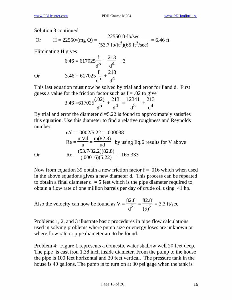
Solution 3 continued: 22550 ft-lb/sec
(53.7 lb/ft3)(65 ft3/sec) Or H = 22550/(mg Q) = = 6.46 ft
Eliminating H gives f
d5213d4 6.46 = 617025 + + 3
fd5
213d4Or 3.46 = 617025 +
This last equation must now be solved by trial and error for f and d. First guess a value for the friction factor such as f = .02 to give
(.02)d5
213d4 3.46 =617025 + =
12341d5
213d4 +
By trial and error the diameter d =5.22 is found to approximately satisfies this equation. Use this diameter to find a relative roughness and Reynolds number. e/d = .0002/5.22 = .000038
Re = mVd
u = m(82.8)
ud by using Eq.6 results for V above
Or Re = (53.7/32.2)(82.8)
(.00016)(5.22) = 165,333
Now from equation 39 obtain a new friction factor f = .016 which when used in the above equations gives a new diameter d. This process can be repeated to obtain a final diameter d = 5 feet which is the pipe diameter required to obtain a flow rate of one million barrels per day of crude oil using 41 hp.
82.8d2
82.8(5)2
Also the velocity can now be found as V = = = 3.3 ft/sec
Problems 1, 2, and 3 illustrate basic procedures in pipe flow calculations used in solving problems where pump size or energy loses are unknown or where flow rate or pipe diameter are to be found. Problem 4: Figure 1 represents a domestic water shallow well 20 feet deep. The pipe is cast iron 1.38 inch inside diameter. From the pump to the house the pipe is 100 feet horizontal and 30 feet vertical. The pressure tank in the house is 40 gallons. The pump is to turn on at 30 psi gage when the tank is
Page 16 of 26 16
www.PDHcenter.com PDH Course M204 www.PDHonline.org
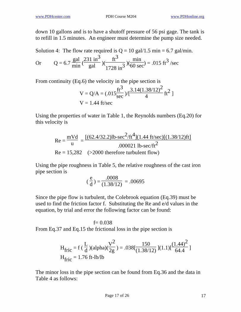
down 10 gallons and is to have a shutoff pressure of 56 psi gage. The tank is to refill in 1.5 minutes. An engineer must determine the pump size needed. Solution 4: The flow rate required is Q = 10 gal/1.5 min = 6.7 gal/min.
231 in3galOr Q = 6.7
galmin ( )(
ft3
1728 in3 )(min
60 sec3) = .015 ft /sec
From continuity (Eq.6) the velocity in the pipe section is
V = Q/A = (.015ft3sec
3.14(1.38/12)24 )/[ ft2 ]
V = 1.44 ft/sec Using the properties of water in Table 1, the Reynolds numbers (Eq.20) for this velocity is
[(62.4/32.2)lb-sec2/ft4](1.44 ft/sec)[(1.38/12)ft].000021 lb-sec/ft2
Re = mVd
u =
Re = 15,282 (>2000 therefore turbulent flow) Using the pipe roughness in Table 5, the relative roughness of the cast iron pipe section is
( ed ) =
.0008(1.38/12) = .00695
Since the pipe flow is turbulent, the Colebrook equation (Eq.39) must be used to find the friction factor f. Substituting the Re and e/d values in the equation, by trial and error the following factor can be found: f= 0.038 From Eq.37 and Eq.15 the frictional loss in the pipe section is
Hfric = f ( Ld )(alpha)(
V22g
(1.44)264.4 ) = .038[
150(1.38/12) ](1.1)[ ]
Hfric = 1.76 ft-lb/lb The minor loss in the pipe section can be found from Eq.36 and the data in Table 4 as follows:
Page 17 of 26 17
www.PDHcenter.com PDH Course M204 www.PDHonline.org
Solution 4 continued: V22g
(1.44)264.4 Hminor = (Centrance +3Celbow +Cexit )( )=[1.0+3(0.7)+1.0][ ]
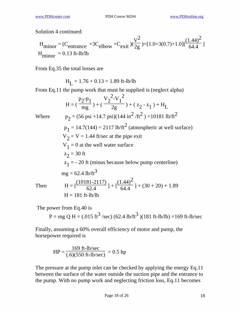
Hminor = 0.13 ft-lb/lb From Eq.35 the total losses are HL = 1.76 + 0.13 = 1.89 ft-lb/lb From Eq.11 the pump work that must be supplied is (neglect alpha)
V2 -V12
2g
2 H = (
p2-p1mg ) + ( ) + ( z2 - z1 ) + HL
Where p2 = (56 psi +14.7 psi)(144 in2 /ft2 ) =10181 lb/ft2 2 (atmospheric at well surface) p1 = 14.7(144) = 2117 lb/ft
V2 = V = 1.44 ft/sec at the pipe exit V1 = 0 at the well water surface z2 = 30 ft z1 = - 20 ft (minus because below pump centerline)
mg = 62.4 lb/ft3 (1.44)2
64.4Then H = [(10181-2117)
62.4 ] + [ ] + (30 + 20) + 1.89
H = 181 ft-lb/lb The power from Eq.40 is
3 P = mg Q H = (.015 ft /sec) (62.4 lb/ft3 )(181 ft-lb/lb) =169 ft-lb/sec Finally, assuming a 60% overall efficiency of motor and pump, the horsepower required is
HP = 169 ft-lb/sec
(.6)(550 ft-lb/sec) = 0.5 hp
The pressure at the pump inlet can be checked by applying the energy Eq.11 between the surface of the water outside the suction pipe and the entrance to the pump. With no pump work and neglecting friction loss, Eq.11 becomes
Page 18 of 26 18

www.PDHcenter.com PDH Course M204 www.PDHonline.org
Solution 4 continued: V1
2
2g p1mg + + z1 =
pentmg +
Vent2
2g + zent
where p1 = 14.7 psi , V1 = 0, z1 = 0, Vent = 1.44 ft/sec, zent =20 ft, and pent , the pressure at the pump entrance, is to be found.
(1.44 ft/sec)2(62.4 lb/ft3)(64.4 ft/sec2)(144 in2/ft2)
(20 ft)(62.4 lb/ft3)144 in2/ft2
14.7 psi + 0 + 0 = pent + +
from which pent = 6 psi which is well above the vapor pressure of water. If the well had been 32 feet deep, the pump entrance pressure would have been pent = 0.8 psi. Since this is approximately the vapor pressure of water, cavitation would probably occur and cause damage to the pump components. Shallow well pumps are usually limited to a suction side lift (or well depth) of about 25 feet. For wells deeper than this a submersible pump can be used at the bottom of the well. Problem 5: The well in problem 4 is converted to a deep well 560 ft deep. A submersible pump is placed at the bottom of the well such that z1 = 0 and the elevation z2 = 560 + 30 = 590 ft. With ever thing else the same, what is the new pump size required? (Neglect additional friction loss) Solution 5: Substituting the calculations from problem 4 and the new well depth into the energy equation Eq.11 gives
(1.44)264.4 H = [
(10181-2117)62.4 ] + [ ] + 590 + 1.89
H = 721 ft-lb/lb From Eq. 40 the power required is
3 P = mg Q H = (.015 ft /sec) (62.4 lb/ft3 )(721 ft-lb/lb) P = 675 ft-lb/sec At 80% efficiency the horsepower required is HP = 675/[(.8)(550)] = 1.5 hp
Page 19 of 26 19
www.PDHcenter.com PDH Course M204 www.PDHonline.org
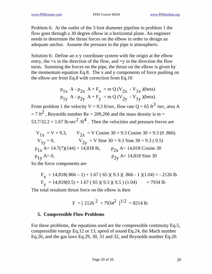
Problem 6: At the outlet of the 3 foot diameter pipeline in problem 1 the flow goes through a 30 degree elbow in a horizontal plane. An engineer needs to determine the thrust forces on the elbow in order to design an adequate anchor. Assume the pressure in the pipe is atmospheric. Solution 6: Define an x-y coordinate system with the origin at the elbow entry, the +x in the direction of the flow, and +y in the direction the flow turns. Summing the forces on the pipe, the thrust on the elbow is given by the momentum equation Eq.8. The x and y components of force pushing on the elbow are from Eq.8 with correction from Eq.10 p1x A - p2x A + Fx = m Q (V2x - V1x )(beta) p1y A - p2y A + Fy = m Q (V2y - V1y )(beta)
From problem 1 the velocity V = 9.3 ft/sec, flow rate Q = 65 ft3 /sec, area A = 7 ft2 , Reynolds number Re = 209,206 and the mass density is m = 53.7/32.2 = 1.67 lb-sec2 /ft4 . Then the velocities and pressure forces are V1x = V = 9.3, V2x = V Cosine 30 = 9.3 Cosine 30 = 9.3 (0 .866) V1y = 0, V2y = V Sine 30 = 9.3 Sine 30 = 9.3 ( 0.5) p1x A= 14.7(7)(144) = 14,818 lb, p2x A= 14,818 Cosine 30 p1y A= 0, p2y A= 14,818 Sine 30 So the force components are Fx = 14,818(.866 – 1) + 1.67 ( 65 )( 9.3 )( .866 - 1 )(1.04) = - 2126 lb Fy = 14,818(0.5) + 1.67 ( 65 )( 9.3 )( 0.5 ) (1.04) = 7934 lb The total resultant thrust force on the elbow is then
2 2 1/2 F = [ 2126 + 7934 ] = 8214 lb
5. Compressible Flow Problems For these problems, the equations used are the compressible continuity Eq.5, compressible energy Eq.12 or 13, speed of sound Eq.24, the Mach number Eq.26, and the gas laws Eq.29, 30, 31 and 32, and Reynolds number Eq.20.
Page 20 of 26 20
www.PDHcenter.com PDH Course M204 www.PDHonline.org
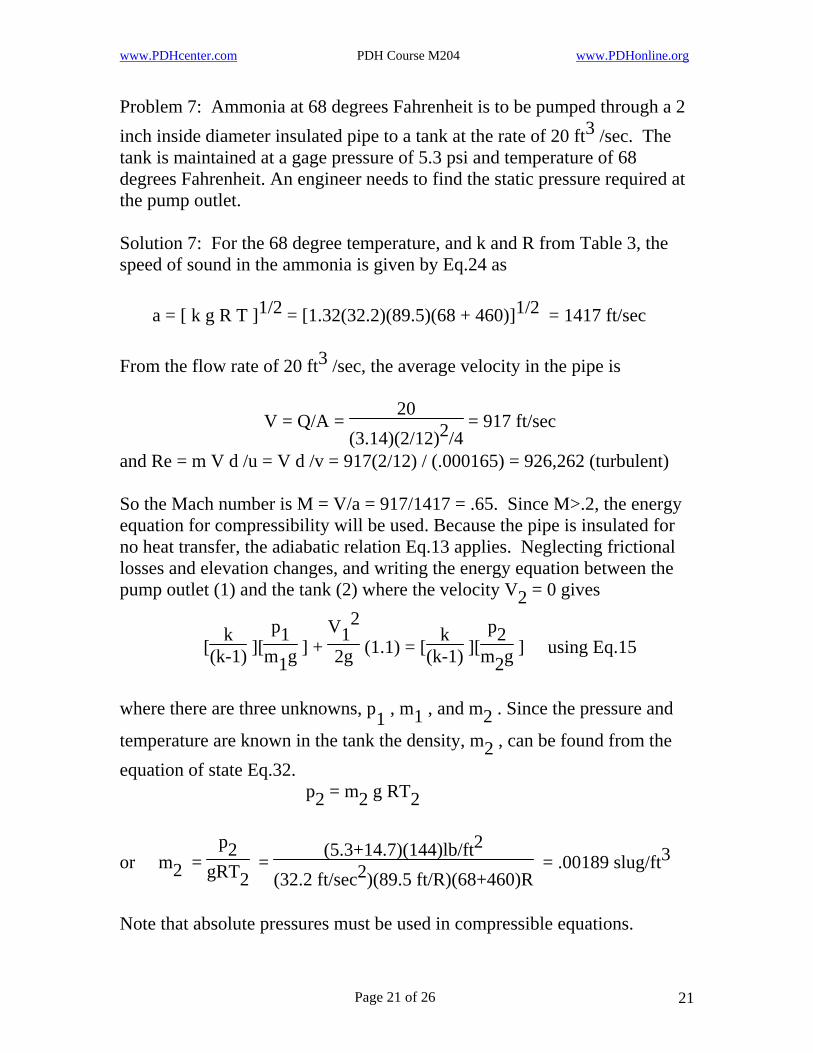
Problem 7: Ammonia at 68 degrees Fahrenheit is to be pumped through a 2 inch inside diameter insulated pipe to a tank at the rate of 20 ft3 /sec. The tank is maintained at a gage pressure of 5.3 psi and temperature of 68 degrees Fahrenheit. An engineer needs to find the static pressure required at the pump outlet. Solution 7: For the 68 degree temperature, and k and R from Table 3, the speed of sound in the ammonia is given by Eq.24 as a = [ k g R T ]1/2 = [1.32(32.2)(89.5)(68 + 460)]1/2 = 1417 ft/sec From the flow rate of 20 ft3 /sec, the average velocity in the pipe is
V = Q/A = 20
(3.14)(2/12)2/4 = 917 ft/sec
and Re = m V d /u = V d /v = 917(2/12) / (.000165) = 926,262 (turbulent) So the Mach number is M = V/a = 917/1417 = .65. Since M>.2, the energy equation for compressibility will be used. Because the pipe is insulated for no heat transfer, the adiabatic relation Eq.13 applies. Neglecting frictional losses and elevation changes, and writing the energy equation between the pump outlet (1) and the tank (2) where the velocity V2 = 0 gives
V12
2g [k
(k-1) ][p1
m1g ] + (1.1) = [k
(k-1) ][p2
m2g ] using Eq.15
where there are three unknowns, p1 , m1 , and m2 . Since the pressure and
temperature are known in the tank the density, m2 , can be found from the equation of state Eq.32. p2 = m2 g RT2
(5.3+14.7)(144)lb/ft2
(32.2 ft/sec2)(89.5 ft/R)(68+460)Ror m2 =
p2gRT2
= = .00189 slug/ft3
Note that absolute pressures must be used in compressible equations.
Page 21 of 26 21
www.PDHcenter.com PDH Course M204 www.PDHonline.org
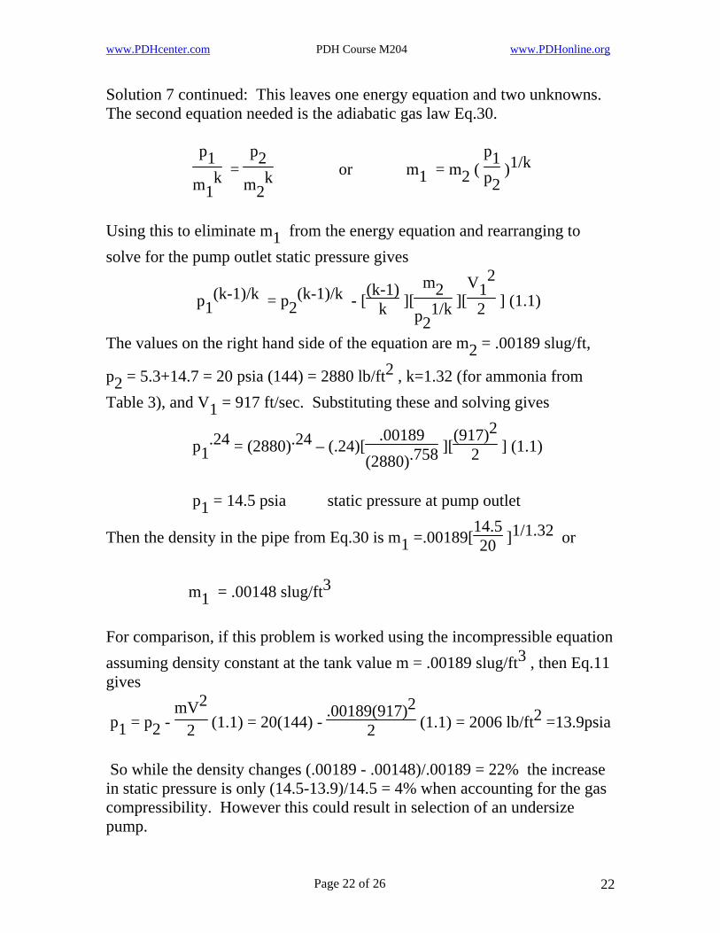
Solution 7 continued: This leaves one energy equation and two unknowns. The second equation needed is the adiabatic gas law Eq.30.
or m1 = m2 ( p1p2
p1m1
kp2
m2k
1/k = )
Using this to eliminate m1 from the energy equation and rearranging to solve for the pump outlet static pressure gives
V12
2m2
p21/k p1
(k-1)/k = p2(k-1)/k - [
(k-1)k ][ ][ ] (1.1)
The values on the right hand side of the equation are m2 = .00189 slug/ft,
p2 = 5.3+14.7 = 20 psia (144) = 2880 lb/ft2 , k=1.32 (for ammonia from Table 3), and V1 = 917 ft/sec. Substituting these and solving gives
(917)22 p1
.24 = (2880).24 – (.24)[.00189
(2880).758 ][ ] (1.1)
p1 = 14.5 psia static pressure at pump outlet
Then the density in the pipe from Eq.30 is m1 =.00189[14.520 ]1/1.32 or
m1 = .00148 slug/ft3 For comparison, if this problem is worked using the incompressible equation assuming density constant at the tank value m = .00189 slug/ft3 , then Eq.11 gives
mV2
2 p1 = p2 - (1.1) = 20(144) - .00189(917)2
2 (1.1) = 2006 lb/ft2 =13.9psia
So while the density changes (.00189 - .00148)/.00189 = 22% the increase in static pressure is only (14.5-13.9)/14.5 = 4% when accounting for the gas compressibility. However this could result in selection of an undersize pump.
Page 22 of 26 22
www.PDHcenter.com PDH Course M204 www.PDHonline.org
Problem 8: Propane flows isothermally in a pipe with a 2 inch inside diameter at a velocity V1 = 650 ft/sec, an absolute pressure p1 = 35 psia, and temperature T1 = 68 degree Fahrenheit. The flow enters a conical diverging section (1) with an outlet (2) 4 inches in diameter. The engineer designing the section and joint has to determine the thrust exerted by the flow on the diverging section. (Re = 984,848 at section 1) Solution 8: The force on the section is from the differences in static pressures and area of the two pipe diameters and the change in momentum of the flow given by Eq.7 with momentum correction from Eq.10
22
12 F = [ p2 A2 - p1 A1 ] + [m2 A 2 V - m1 A1 V ] (beta)
The density m1 can be found from the equation of state Eq.32 or
m1 = p1
gRT135(144)lb/ft2
(32.2 ft/sec2)(35 ft/R)(68+460)R2 = = .00847 lb-sec /ft4
where the gas constant R=35 is from Table 3. Now the pressure p2 , velocity V2 and density m2 must be found. Starting with Eq.12 the compressible isothermal energy equation applied at sections 1 and 2 across the diverging section where there is no pump and no elevation change, neglecting friction loss, gives, with correction from Eq.15
V12
2g p1
m1gV22g
2(alpha) =
p2m2g loge p1 + loge p2 + (alpha)
Since there are 3 unknowns in this equation, two additional equations are needed. These are the isothermal gas relation Eq.29 and the compressible continuity equation Eq.5.
Eq.29 p1m1
= p2m2
or m1m2
= p1p2
Eq.5 V2 = m1A1m2A2
V1 = p1A1p2A2
V1
Substituting these relations into the energy equation to eliminate m2 and V2 and rearranging gives
V12
2g p1
m1g loge p2p1
[ 1 –( p1p2
= )2 ( A1A2
2 ) ] (alpha)
Page 23 of 26 23
www.PDHcenter.com PDH Course M204 www.PDHonline.org
Solution 8 continued: The last equation has only one unknown, p2 , and can be solved by successive trial guesses. An initial guess for p2 could be 48 psia. Second and third trials could be higher and lower to find which causes the equation to converge. In this manner it is found the pressure p2 is p2 = 51 psia Then using continuity Eq.5 above, the velocity V2 is
V2 = ( 3551 )(
22
42 ) (650) = 112 ft/sec
From the gas law the density m2 is
m2 = .00847 ( 5135 ) = .0123 lb-sec2 4 /ft
With all flow properties now determined, the force on the divergent section of pipe can now be found.
F = (51)(3.14
4 )(4)2 – (35)(3.14
4 )(2)2
+ .0123(3.14
4 )(412 )2 (112)2 (1.04) - .00847(
3.144 )(
212 )2 (650)2 (1.04)
F = 641 - 110 + 14.0 - 81 = 464 lb
6. Unsteady Flow Problem 9: A mile long section of crude oil pipe line 3 feet in diameter is shut down for repairs by closing a valve at the outlet and turning off the pump at the inlet so the pipe is filled with liquid at zero velocity. After completion of repairs, the pump is started and the valve opened. The pump supplies a constant head equivalent of a 44.7 ft column of crude oil. An engineer must determine the time for the fluid to be accelerated to the final velocity and return the pipe flow to full capacity. Solution 9: In this case the final velocity is known from problem 1 as 9.3 ft/sec. If this velocity is not known, an estimate can be made from Eq.11 the energy equation. The final velocity will be that velocity at which the friction losses from the Darcy-Weisbach equation Eq.37, are equal to the pump head supplied, neglecting other minor losses. From the energy equation this is
H = f ( Ld ) (alpha ) (
Vf2
2g )
Page 24 of 26 24
www.PDHcenter.com PDH Course M204 www.PDHonline.org
Solution 9 continued: Estimating an f = .018 gives
Vf = [ 2gdH
fL(alpha) ]1/2 = [
2(32.2)(3)(44.7).018(5280)(1.1)
1/2 ]
Vf = 9.1 ft/sec At velocity less than this final velocity, the frictional loss will be less than the pump head so that there is unbalanced head given by
H – f( Ld )(alpha)(
V22g ) > 0
Or f ( Ld )(alpha)(
12g f
2 2 )[ V - V ] > 0
The time to establish the final velocity can be determined from Newton’s equation of motion, force F = mass x acceleration. The force F is given by the unbalanced head above times the weight of a column of fluid of cross section area A. This force accelerates the mass of fluid in the pipe of section A and length L or
] = mAL ( dVdt mgAf (
Ld )(alpha)(
12g )[ Vf
2 2 - V )
Rearranging to separate the variables of this differential equation gives
dt = 2d
f(alpha) [ dV
(Vf2 - V2)
]
LVf2
gHFrom the first equation 2d
f(alpha) = so the above equation becomes
LVf2
gH2Vf dV
(Vf2 - V2)
dt = [ dV
(Vf2 - V2)
] = LVf2gH [ ]
Integrating both sides gives the final expression
t = LVf2gH ln [
(Vf + V)(Vf - V) ]
From this equation it can be seen that it would take an infinite time for V to become Vf . For practical applications, V= .95 Vf can be considered the final velocity. The corresponding time is
t = 5280(9.1)
2(32.2)(44.7) ln [1.95.05 ] = 61 seconds
This is the time required for the pipe flow to reach steady state conditions.
Page 25 of 26 25
www.PDHcenter.com PDH Course M204 www.PDHonline.org
Course Summary This course has presented basic methods of solving problems of fluid flow in pipes. The compressibility and viscosity properties of liquids and gasses were reviewed. For both compressible and incompressible fluids, and for isothermal and adiabatic gases, the governing equations of continuity, momentum, and energy were presented. Gas laws and relations for acoustic velocity, Mach number, and Reynolds number were also given. Equations for energy loss in pipe flow due to viscous friction and pipe fittings were defined. Relations for friction factors for both laminar and turbulent flow were included. Velocity profiles were shown for laminar and turbulent flow. Example problems were presented for incompressible and compressible and adiabatic and isothermal pipe flow. Different solution methods were shown for finding various flow quantities for viscous turbulent steady uniform flow. Examples of thrust forces on pipe fittings using momentum equations were included. Finally, a problem of unsteady flow was presented.
References
1. Fluid Mechanics, Victor L Streeter, McGraw-Hill, 1958 2. Fluid Mechanics & Hydraulics, Ranald V. Giles, McGraw-Hill, 1962 3. Mechanical Engineering, Gerald Coren, Arco Publishing, 1965 4. Standard Handbook for Mechanical Engineers, Theodore Baumeister
and Lionel S. Marks, McGraw-Hill, 1967
Page 26 of 26 26