pip20 / pip22 bios v2 - mpl ag1.1 bios features the pip20 / pip22 bios v2.xy supports the following...
TRANSCRIPT

PIP20 / PIP22 BIOS V2.xy
System Configuration Utility Main Exit Boot POST PnP SIO Features Firmbase Misc >+--------------------------------------------------------+---------------------+| System Summary |Use TAB to switch || -------------------------------------------------------|between month, day || Phoenix[R] System BIOS |and year. Use digits|| BIOS Version EB(SF).005 |and BKSP to change || BIOS Build Date 10/29/09 |field. || System BIOS Size 128KB | || CPM/CSPM/BPM Modules P7C7, 945GM, PIP20 | || StrongFrame(R) Technology, Firmbase(R) Technology | || | || Processor (CPU) | || Genuine Intel(R) CPU L2400 @ 1.66GHz | || Processor Count 2 | || | || System Memory (RAM) | || Low Memory (KB) 625 | || Extended Memory (KB) 3128128 | || | || Real Time Clock (RTC) | || RTC Date [04/15/2009] | |+--------------------------------------------------------+---------------------+Embedded BIOS(R) w/StrongFrame(R) Technology - (c)2008 Phoenix Technologies Ltd
2009 by MPL AG 1 MEH-10126-101 Rev. C
PIP20 / PIP22
SYSTEM BIOS USER MANUALH ig h -Te c h • M a d e in Sw itze r l a n d

TABLE OF CONTENTS
1 INTRODUCTION.................................................................................................................. 61.1 BIOS FEATURES.........................................................................................................61.2 ABOUT THIS MANUAL................................................................................................61.3 MANUAL REVISIONS..................................................................................................7
1.3.1 RELATED PRODUCTS........................................................................................71.3.2 REVISION HISTORY...........................................................................................7
1.4 RELATED DOCUMENTATION....................................................................................7
2 HARDWARE CONFIGURATION..........................................................................................82.1 INTERRUPTS (IRQs)...................................................................................................82.2 MEMORY..................................................................................................................... 92.3 I/O............................................................................................................................... 112.4 EXAMPLE CONFIGURATION....................................................................................122.5 GRAPHICS CONFIGURATION..................................................................................13
2.5.1 INTEGRATED GRAPHICS CONTROLLER.......................................................132.5.2 FLAT PANEL DISPLAY (LVDS) INTERFACE....................................................13
2.5.2.1 18 BIT COLOR DEPTH..............................................................................132.5.2.2 24 BIT COLOR DEPTH (OPTIONAL).........................................................142.5.2.3 BACKLIGHT INVERTER TYPES...............................................................142.5.2.4 BIOS CONFIGURATION............................................................................15
2.5.2.4.1 PANEL BACKLIGHT..........................................................................152.5.2.4.2 PANEL BRIGHTNESS.......................................................................152.5.2.4.3 PANEL FITTING.................................................................................15
3 BIOS................................................................................................................................... 163.1 BIOS UPDATE...........................................................................................................163.2 BOOT SCREEN.........................................................................................................17
3.2.1 POST SCREEN..................................................................................................173.2.2 PCI DEVICES.....................................................................................................183.2.3 POST INTERVENTION......................................................................................18
3.3 SETUP SCREEN STRUCTURE.................................................................................193.3.1 INTRODUCTION................................................................................................193.3.2 MENUS..............................................................................................................193.3.3 NAVIGATION.....................................................................................................20
3.4 BOOT ACTION MENU...............................................................................................213.5 MAIN SETUP MENU..................................................................................................22
3.5.1 SYSTEM SUMMARY.........................................................................................223.5.2 REAL TIME CLOCK (RTC)................................................................................223.5.3 MPL INFORMATION..........................................................................................23
3.5.3.1 MPL BOARD INFORMATION....................................................................233.5.3.2 MPL BIOS INFORMATION........................................................................23
3.6 EXIT SETUP MENU...................................................................................................243.6.1 SAVE, RESTORE AND EXIT SETUP................................................................24
3.6.1.1 SAVE SETTINGS AND RESTART.............................................................243.6.1.2 EXIT SETUP WITHOUT SAVING CHANGES............................................253.6.1.3 RELOAD FACTORY-DEFAULTS AND RESTART....................................25
3.6.2 SAVE, RESTORE AND EXIT SETUP – USE PERMANENT STORAGE...........263.6.2.1 SAVE SETTINGS, STORE TO FLASH AND RESTART............................263.6.2.2 LOAD SETTINGS FROM FLASH AND RESTART....................................263.6.2.3 CLEAR SETTINGS IN FLASH...................................................................27
3.7 BOOT SETUP MENU.................................................................................................283.7.1 SYSTEM BOOT CONFIGURATION...................................................................28
2009 by MPL AG 2 MEH-10126-101 Rev. C
PIP20 / PIP22
SYSTEM BIOS USER MANUALH ig h -Te c h • M a d e in Sw itze r l a n d

3.7.1.1 BOOT DEVICE PRIORITIZATION (BBS)...................................................283.7.1.2 INITIALIZATION POLICY...........................................................................293.7.1.3 IDE DRIVE CONFIGURATION..................................................................30
3.7.2 ICH ATA CONTROLLER CONFIGURATION.....................................................313.7.2.1 SATA CONTROLLER.................................................................................31
3.7.2.1.1 RAID...................................................................................................323.7.2.1.2 COMBINED MODE............................................................................33
3.7.2.2 PATA CONTROLLER.................................................................................333.8 POST SETUP MENU.................................................................................................34
3.8.1 POST MEMORY TESTS....................................................................................343.8.1.1 LOW MEMORY STANDARD TEST...........................................................343.8.1.2 LOW MEMORY EXHAUSTIVE TEST........................................................343.8.1.3 HIGH MEMORY STANDARD TEST...........................................................343.8.1.4 HIGH MEMORY EXHAUSTIVE TEST........................................................343.8.1.5 CLICK DURING MEMORY TEST..............................................................353.8.1.6 CLEAR MEMORY DURING TEST.............................................................35
3.8.2 POST ERROR CONTROL.................................................................................353.8.2.1 PAUSE ON POST ERRORS......................................................................35
3.8.3 POST USER INTERFACE.................................................................................353.8.3.1 POST DISPLAY MESSAGES....................................................................353.8.3.2 POST OPERATOR PROMPT....................................................................353.8.3.3 DISPLAY PCI DEVICES.............................................................................363.8.3.4 DISPLAY PNP DEVICES...........................................................................36
3.8.4 POST DEBUGGING...........................................................................................363.8.5 DEVICE INITIALIZATION...................................................................................36
3.8.5.1 POST FLOPPY SEEK................................................................................363.8.5.2 POST HARD DISK SEEK...........................................................................36
3.9 PNP SETUP MENU....................................................................................................373.9.1 PLUG-N-PLAY (PNP) CONFIGURATION..........................................................37
3.9.1.1 PLUG-N-PLAY...........................................................................................373.9.1.2 PLUG-N-PLAY OS.....................................................................................37
3.9.2 IRQS RESERVED FOR PLUG-N-PLAY.............................................................383.9.3 DMA CHANNELS RESERVED FOR PLUG-N-PLAY.........................................39
3.10 SIO SETUP MENU...................................................................................................403.10.1 SERIAL PORT 1 SETTINGS............................................................................403.10.2 SERIAL PORT 3 SETTINGS............................................................................413.10.3 SERIAL PORT 2 SETTINGS............................................................................413.10.4 SERIAL PORT 4 SETTINGS............................................................................423.10.5 PARALLEL PORT SETTINGS..........................................................................43
3.11 FEATURES SETUP MENU......................................................................................443.11.1 BIOS FEATURE CONFIGURATION................................................................44
3.11.1.1 INTERRUPT PROCESSING....................................................................443.11.1.2 MP TABLES (NON-ACPI OSES).............................................................443.11.1.3 ACPI.........................................................................................................443.11.1.4 POST MEMORY MANAGER...................................................................453.11.1.5 SYSTEM MANAGEMENT BIOS..............................................................453.11.1.6 SPLASH SCREEN...................................................................................45
3.11.2 CONSOLE REDIRECTION..............................................................................453.11.2.1 USE CONSOLE ASSIGNMENTS BELOW...............................................453.11.2.2 POST CONSOLE.....................................................................................463.11.2.3 PREBOOT CONSOLE.............................................................................463.11.2.4 DEBUGGER CONSOLE..........................................................................46
3.11.3 CPU CONFIGURATION...................................................................................473.11.3.1 P7 GEYSERVILLE/SPEEDSTEP.............................................................473.11.3.2 INTEL VT..................................................................................................473.11.3.3 MICROCODE UPDATE............................................................................473.11.3.4 CORE MULTI-PROCESSING..................................................................47
2009 by MPL AG 3 MEH-10126-101 Rev. C
PIP20 / PIP22
SYSTEM BIOS USER MANUALH ig h -Te c h • M a d e in Sw itze r l a n d

3.12 FIRMBASE SETUP MENU.......................................................................................483.12.1 FEATURES ENABLED BY FIRMBASE[R] TECHNOLOGY.............................48
3.12.1.1 LEGACY USB..........................................................................................483.12.1.2 USB BOOT...............................................................................................483.12.1.3 EHCI/USB 2.0..........................................................................................49
3.12.2 BASIC FIRMBASE[R] TECHNOLOGY CONFIGURATION..............................493.12.2.1 FIRMBASE TECHNOLOGY.....................................................................493.12.2.2 FIRMBASE DEBUG LOG.........................................................................493.12.2.3 FIRMBASE SYSTEM CONSOLE.............................................................493.12.2.4 FIRMBASE SHELL ON SERIAL PORT....................................................49
3.13 MISC SETUP MENU................................................................................................503.13.1 CACHE CONTROL..........................................................................................50
3.13.1.1 SYSTEM CACHE.....................................................................................503.13.2 KEYBOARD CONTROL...................................................................................50
3.13.2.1 KEYBOARD NUMLOCK LED...................................................................503.13.2.2 TYPEMATIC RATE..................................................................................513.13.2.3 TYPEMATIC DELAY................................................................................51
3.13.3 MISCELLANEOUS BIOS CONFIGURATION..................................................513.13.3.1 LOWERCASE HEX DISPLAYS................................................................51
3.14 SPECIAL SETUP MENU..........................................................................................523.14.1 AC97 AUDIO CONFIGURATION.....................................................................52
3.14.1.1 AC97 AUDIO SUPPORT..........................................................................523.14.2 PC/104 MEMORY CONFIGURATION.............................................................52
3.14.2.1 PC/104 MEM BASE ADDRESS...............................................................523.14.2.2 PC/104 MEM LENGTH.............................................................................53
3.14.3 PS/2 CONNECTOR CONFIGURATION...........................................................533.14.3.1 PS/2 CONNECTOR MODE......................................................................53
3.15 VIDEO SETUP MENU..............................................................................................543.15.1 LVDS PANEL SETTINGS................................................................................54
3.15.1.1 PANEL BACKLIGHT................................................................................543.15.1.2 PANEL BRIGHTNESS (PERCENT).........................................................543.15.1.3 PANEL FITTING.......................................................................................55
3.15.2 GMCH SETTINGS............................................................................................553.15.2.1 INITIALIZE IGD ON S3 RESUME............................................................553.15.2.2 IGD FUNCTION 1.....................................................................................553.15.2.3 VIDEO FRAME BUFFER SIZE................................................................55
3.16 ADVANCED INFO SETUP MENU............................................................................563.16.1 CPU INFORMATION........................................................................................56
3.16.1.1 CPU MODEL AND STEPPING................................................................563.16.1.2 CPU MICROCODE VERSION.................................................................563.16.1.3 ON-DIE THERMAL SENSOR, °C.............................................................56
3.16.2 ETHERNET INFORMATION............................................................................563.16.2.1 LAN 1 MAC ADDRESS............................................................................563.16.2.2 LAN 2 MAC ADDRESS............................................................................56
4 NETWORK BOOT (PXE)....................................................................................................574.1 PXE SETUP MENU....................................................................................................57
4.1.1 CONFIGURATION OPTIONS............................................................................584.1.2 KEY ASSIGNMENTS.........................................................................................58
4.2 BOOTING FROM NETWORK....................................................................................58
5 COPYRIGHT...................................................................................................................... 60
6 DISCLAIMER......................................................................................................................60
7 TRADEMARKS................................................................................................................... 60
2009 by MPL AG 4 MEH-10126-101 Rev. C
PIP20 / PIP22
SYSTEM BIOS USER MANUALH ig h -Te c h • M a d e in Sw itze r l a n d

8 SUPPORT..........................................................................................................................60
2009 by MPL AG 5 MEH-10126-101 Rev. C
PIP20 / PIP22
SYSTEM BIOS USER MANUALH ig h -Te c h • M a d e in Sw itze r l a n d

1 INTRODUCTION
1.1 BIOS FEATURESThe PIP20 / PIP22 BIOS V2.xy supports the following standards and key features:
• ACPI 1.0• Plug'n'Play• USB Boot (Floppy disk, CD-ROM, Hard disk)• USB Legacy Keyboard and Mouse• PXE Network Boot
1.2 ABOUT THIS MANUALThis manual provides all the information necessary to configure the PIP20/PIP22 BIOS. The manual is written for technical personnel. It is recommended to use this manual in combination with the PIP20/PIP22 User Manual.
NOTEIt is strongly recommended to read the PIP20/PIP22 User Manual, the PIP20/PIP22
Technical Reference Manual and also this manual before the PIP20/PIP22 is switched on.
2009 by MPL AG 6 MEH-10126-101 Rev. C
PIP20 / PIP22
SYSTEM BIOS USER MANUALH ig h -Te c h • M a d e in Sw itze r l a n d

1.3 MANUAL REVISIONS
1.3.1 RELATED PRODUCTS
Manual Revision Related ToA PIP20/PIP22 BIOS V1.30B PIP20/PIP22 BIOS V1.35C PIP20/PIP22 BIOS V2.00
1.3.2 REVISION HISTORY
Manual Revision Date DescriptionA 2008-02-21 Initial release of this document.B 2008-06-16 Updated to reflect BIOS V1.35 featuresC 2009-10-29 Updated to reflect BIOS V2.00 features
1.4 RELATED DOCUMENTATIONThe following documents are related to this manual. For detailed Information about a specific PIP feature or setting please refer to these additional manuals.
Reference Description Available from[1] PIP20/PIP22 User Manual MPL AG: http://www.mpl.ch/6000.html[2] PIP20/PIP22 Technical Reference Manual MPL AG: http://www.mpl.ch/6000.html
2009 by MPL AG 7 MEH-10126-101 Rev. C
PIP20 / PIP22
SYSTEM BIOS USER MANUALH ig h -Te c h • M a d e in Sw itze r l a n d

2 HARDWARE CONFIGURATION
2.1 INTERRUPTS (IRQs)The standard PC AT architecture is limited to 16 Interrupts (IRQs). The following table shows the typical usage of the available interrupt lines on the PIP.
Please consult this table before changing IRQ assignments of devices in the BIOS or adding PC/104 expansion cards in order to avoid conflicts and to make sure that there will be sufficient IRQs available.
The PIP standard configuration uses all but two interrupts (5 and 11). IRQ 12 is also available if the following two conditions are met:
• 'PS/2 CONNECTOR MODE' (refer to section 3.14.3.1) is set to 'Mouse Disabled' or set to 'Auto (Y-cable) ' and no PS/2 mouse is connected
• 'LEGACY USB' (refer to section 3.12.1.1) is disabled
Additional interrupts can be made available by disabling onboard devices. Onboard devices that can be configured to use different interrupts are marked 'Configurable' in the table below.
IRQ Usage Remarks PIP default configuration0 System Timer Not available1 Keyboard Not available2 Cascade Not available3 Serial Port 2 / Serial Port 4 Configurable / Available for PC/104 Used4 Serial Port 1 / Serial Port 3 Configurable / Available for PC/104 Used5 Not used Configurable / Available for PC/104 Available6 Floppy Disk Controller Available for PC/104 Used7 Parallel Port Configurable / Available for PC/104 Used8 Real Time Clock (RTC) Not available9 PCI Devices Not available
10 PCI Devices Not available11 PCI Devices Not available12 PS/2 Mouse Available for PC/104 if PS/2 mouse disabled and Usb Legacy
disabled13 Floating Point Unit (FPU) Not available14 Primary ATA Channel Not available15 Secondary ATA Channel Not available
For a PC/104 card configuration example, please refer to section 2.4.
2009 by MPL AG 8 MEH-10126-101 Rev. C
PIP20 / PIP22
SYSTEM BIOS USER MANUALH ig h -Te c h • M a d e in Sw itze r l a n d

2.2 MEMORYPC/104 (ISA) and PC/104-Plus (PCI) add-on cards may require a certain amount of memory for installing their Option ROMs or they have onboard memory that needs to be mapped into the system memory space.The memory area used for this purpose is limited to 000CF000h – 000DFFFFh.
The area 000C0000h – 000CF000h is used by the VGA BIOS and is therefore not available for other devices. The system BIOS is located at 000E0000h – 000FFFFFh (128kB).
This leaves the memory range 000CF000h – 000E0000h (68kB) to be used as memory for Option ROMs and/or, from address 000D0000h on, for PC/104 cards. The onboard Option ROMs (PXE Network Boot, RAID) use this area of memory as well, if they are enabled.
The PC/104 Memory can be enabled in blocks of 16kB (4000h) size, starting at addresses 000D0000h (= segment D000), 000D4000h (= segment D400), 000D8000h (= segment D800) or 000DC000 (= segment DC00). Please refer to section 3.14.2 for the detailed options.
The following is an illustration of the PIP's memory map:
2009 by MPL AG 9 MEH-10126-101 Rev. C
PIP20 / PIP22
SYSTEM BIOS USER MANUALH ig h -Te c h • M a d e in Sw itze r l a n d
↑SystemBIOS
VGABIOS
↓
000DC000h
000D8000h
000D4000h
000D0000h
000E0000h
000CF000h
Available for PC/104 cards or Option ROMs
Available for Option ROMs only
000E0000h
PC/104 Memory
↓
Option ROMs
↓
16kB
16kB
16kB
16kB

The onboard Option ROMs, if enabled, require a certain amount of memory during their initialization and another for their execution. As with almost all Option ROMs, the amount of memory required for their execution is much smaller than during the initialization.
The following table shows the memory requirements for the onboard Option ROMs.
Memory needed for initialization Memory needed for executionPXE ROM 59kB (EC00h) 4kB (1000h)RAID ROM 55kB (DC00h) 16kB (4000h)
Please note that even if the system had enough free memory for the execution of an Option ROM, it is the amount of memory required during the initialization that defines whether or not a Option ROM can be executed.
The figure below shows the resulting memory map if the Option ROMs are initialized in the following order:1. PXE ROM for Ethernet 12. PXE ROM for Ethernet 23. RAID ROM
This is what happens at initialization:• The PXE ROM for Ethernet 1 gets initialized. It temporarily occupies the memory from 000CF000h to
000DDC00h (59kB).After initialization, it uses the memory range 000CF000h – 000D0000h (1kB).
• The PXE ROM for Ethernet 2 gets initialized. It temporarily occupies the memory from 000D000h to 000DEC00h (59kB).After initialization, it uses the memory range 000D0000h – 000D1000h (1kB).
• The RAID ROM gets initialized. It temporarily occupies the memory from 000D1000h to 000DEC00h (55kB).After initialization, it uses the memory range 000D1000h – 000D5000h (16kB).
NOTE: If the RAID ROM would have been initialized first, it ended up using the memory range000CF000h – 000D3000h. This would have left only 52kB of memory free, so the PXE ROM would not have been able to initialize anymore as it requires 59kB of memory for initialization.
2009 by MPL AG 10 MEH-10126-101 Rev. C
PIP20 / PIP22
SYSTEM BIOS USER MANUALH ig h -Te c h • M a d e in Sw itze r l a n d
PXE ROM
RAID ROM
↑SystemBIOS
VGABIOS
↓
000DC000h
000D8000h
000D4000h
000D0000h
000E0000h
000CF000h
000E0000h
PC/104 Memory
↓
Option ROMs
↓
Available for PC/104 cards or Option ROMs
Available for Option ROMs only
PXE ROM
000D5000h
000D0000h000D1000h
000CF000h
Used by Option ROMs

2.3 I/OInput/Output space is required by most PC/104 cards. The table below is an overview of the PIP's I/O space usage from 0000h to 03FFh, which is the important range for PC/104 cards.
'Configurable' devices can be set up to use a different I/O range, or can be disabled completely.
I/O range Usage Remarks PIP20/PIP22 default configuration03F8h – 03FFh Serial port Configurable Used03F7h – 03F7h Floppy disk controller Configurable Used03F6h – 03F6h Primary ATA channel Not available03F0h – 03F5h Floppy disk controller Configurable Used03E8h – 03EFh Serial port Configurable Used03C0h – 03DFh VGA Not available03B0h – 03BBh VGA Not available0378h – 037Fh Parallel port Configurable Used0376h – 0376h Secondary ATA channel Not available0338h – 033Fh Serial port Configurable Available02F8h – 02FFh Serial port Configurable Used02E8h – 02EFh Serial port Configurable Used0278h – 027Fh Parallel port Configurable Available0238h – 023Fh Serial port Configurable Available0228h – 022Fh Serial port Configurable Available0220h – 0227h Serial port Configurable Available01F0h – 01F7h Primary ATA channel Not available0170h – 0177h Secondary ATA channel Not available0000h – 00FFh Various system devices Not available
This leads to the following consecutive I/O ranges that can be used by PC/104 cards on a PIP with default configuration:
• 100h – 16Fh• 180h – 1EFh• 200h – 2DFh• 300h – 370h• 380h – 3AFh
For a PC/104 card configuration example, please refer to section 2.4.
2009 by MPL AG 11 MEH-10126-101 Rev. C
PIP20 / PIP22
SYSTEM BIOS USER MANUALH ig h -Te c h • M a d e in Sw itze r l a n d
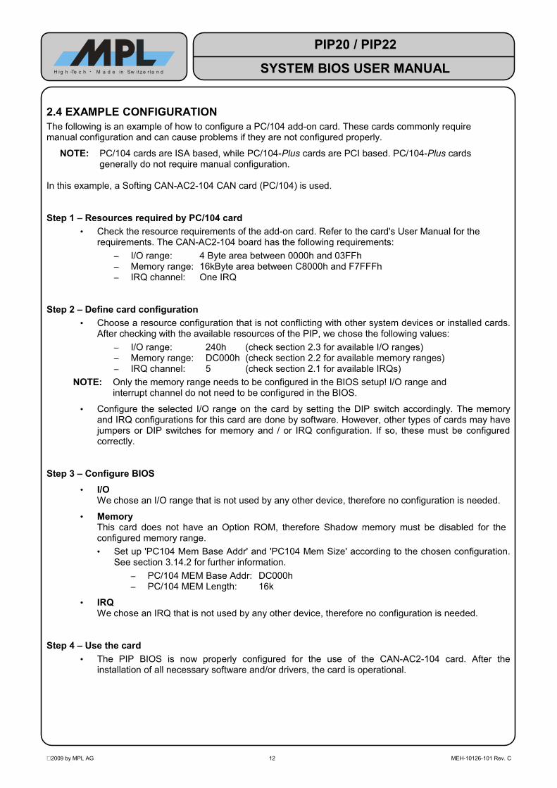
2.4 EXAMPLE CONFIGURATIONThe following is an example of how to configure a PC/104 add-on card. These cards commonly require manual configuration and can cause problems if they are not configured properly.
NOTE: PC/104 cards are ISA based, while PC/104-Plus cards are PCI based. PC/104-Plus cards generally do not require manual configuration.
In this example, a Softing CAN-AC2-104 CAN card (PC/104) is used.
Step 1 – Resources required by PC/104 card• Check the resource requirements of the add-on card. Refer to the card's User Manual for the
requirements. The CAN-AC2-104 board has the following requirements:– I/O range: 4 Byte area between 0000h and 03FFh– Memory range: 16kByte area between C8000h and F7FFFh– IRQ channel: One IRQ
Step 2 – Define card configuration• Choose a resource configuration that is not conflicting with other system devices or installed cards.
After checking with the available resources of the PIP, we chose the following values:– I/O range: 240h (check section 2.3 for available I/O ranges)– Memory range: DC000h (check section 2.2 for available memory ranges)– IRQ channel: 5 (check section 2.1 for available IRQs)
NOTE: Only the memory range needs to be configured in the BIOS setup! I/O range and interrupt channel do not need to be configured in the BIOS.
• Configure the selected I/O range on the card by setting the DIP switch accordingly. The memory and IRQ configurations for this card are done by software. However, other types of cards may have jumpers or DIP switches for memory and / or IRQ configuration. If so, these must be configured correctly.
Step 3 – Configure BIOS• I/O
We chose an I/O range that is not used by any other device, therefore no configuration is needed.
• MemoryThis card does not have an Option ROM, therefore Shadow memory must be disabled for the configured memory range.• Set up 'PC104 Mem Base Addr' and 'PC104 Mem Size' according to the chosen configuration.
See section 3.14.2 for further information.– PC/104 MEM Base Addr: DC000h– PC/104 MEM Length: 16k
• IRQWe chose an IRQ that is not used by any other device, therefore no configuration is needed.
Step 4 – Use the card• The PIP BIOS is now properly configured for the use of the CAN-AC2-104 card. After the
installation of all necessary software and/or drivers, the card is operational.
2009 by MPL AG 12 MEH-10126-101 Rev. C
PIP20 / PIP22
SYSTEM BIOS USER MANUALH ig h -Te c h • M a d e in Sw itze r l a n d
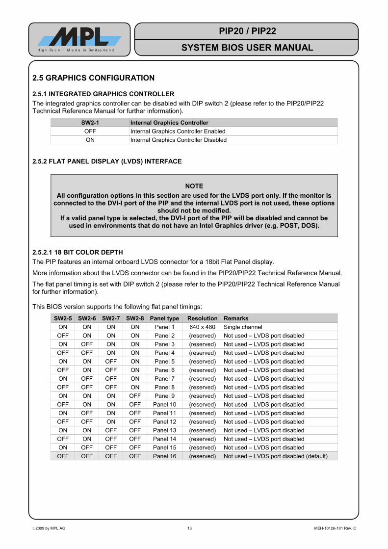
2.5 GRAPHICS CONFIGURATION
2.5.1 INTEGRATED GRAPHICS CONTROLLERThe integrated graphics controller can be disabled with DIP switch 2 (please refer to the PIP20/PIP22 Technical Reference Manual for further information).
SW2-1 Internal Graphics ControllerOFF Internal Graphics Controller EnabledON Internal Graphics Controller Disabled
2.5.2 FLAT PANEL DISPLAY (LVDS) INTERFACE
NOTEAll configuration options in this section are used for the LVDS port only. If the monitor is
connected to the DVI-I port of the PIP and the internal LVDS port is not used, these options should not be modified.
If a valid panel type is selected, the DVI-I port of the PIP will be disabled and cannot be used in environments that do not have an Intel Graphics driver (e.g. POST, DOS).
2.5.2.1 18 BIT COLOR DEPTHThe PIP features an internal onboard LVDS connector for a 18bit Flat Panel display.
More information about the LVDS connector can be found in the PIP20/PIP22 Technical Reference Manual.
The flat panel timing is set with DIP switch 2 (please refer to the PIP20/PIP22 Technical Reference Manual for further information).
This BIOS version supports the following flat panel timings:
SW2-5 SW2-6 SW2-7 SW2-8 Panel type Resolution RemarksON ON ON ON Panel 1 640 x 480 Single channelOFF ON ON ON Panel 2 (reserved) Not used – LVDS port disabledON OFF ON ON Panel 3 (reserved) Not used – LVDS port disabledOFF OFF ON ON Panel 4 (reserved) Not used – LVDS port disabledON ON OFF ON Panel 5 (reserved) Not used – LVDS port disabledOFF ON OFF ON Panel 6 (reserved) Not used – LVDS port disabledON OFF OFF ON Panel 7 (reserved) Not used – LVDS port disabledOFF OFF OFF ON Panel 8 (reserved) Not used – LVDS port disabledON ON ON OFF Panel 9 (reserved) Not used – LVDS port disabledOFF ON ON OFF Panel 10 (reserved) Not used – LVDS port disabledON OFF ON OFF Panel 11 (reserved) Not used – LVDS port disabledOFF OFF ON OFF Panel 12 (reserved) Not used – LVDS port disabledON ON OFF OFF Panel 13 (reserved) Not used – LVDS port disabledOFF ON OFF OFF Panel 14 (reserved) Not used – LVDS port disabledON OFF OFF OFF Panel 15 (reserved) Not used – LVDS port disabledOFF OFF OFF OFF Panel 16 (reserved) Not used – LVDS port disabled (default)
2009 by MPL AG 13 MEH-10126-101 Rev. C
PIP20 / PIP22
SYSTEM BIOS USER MANUALH ig h -Te c h • M a d e in Sw itze r l a n d
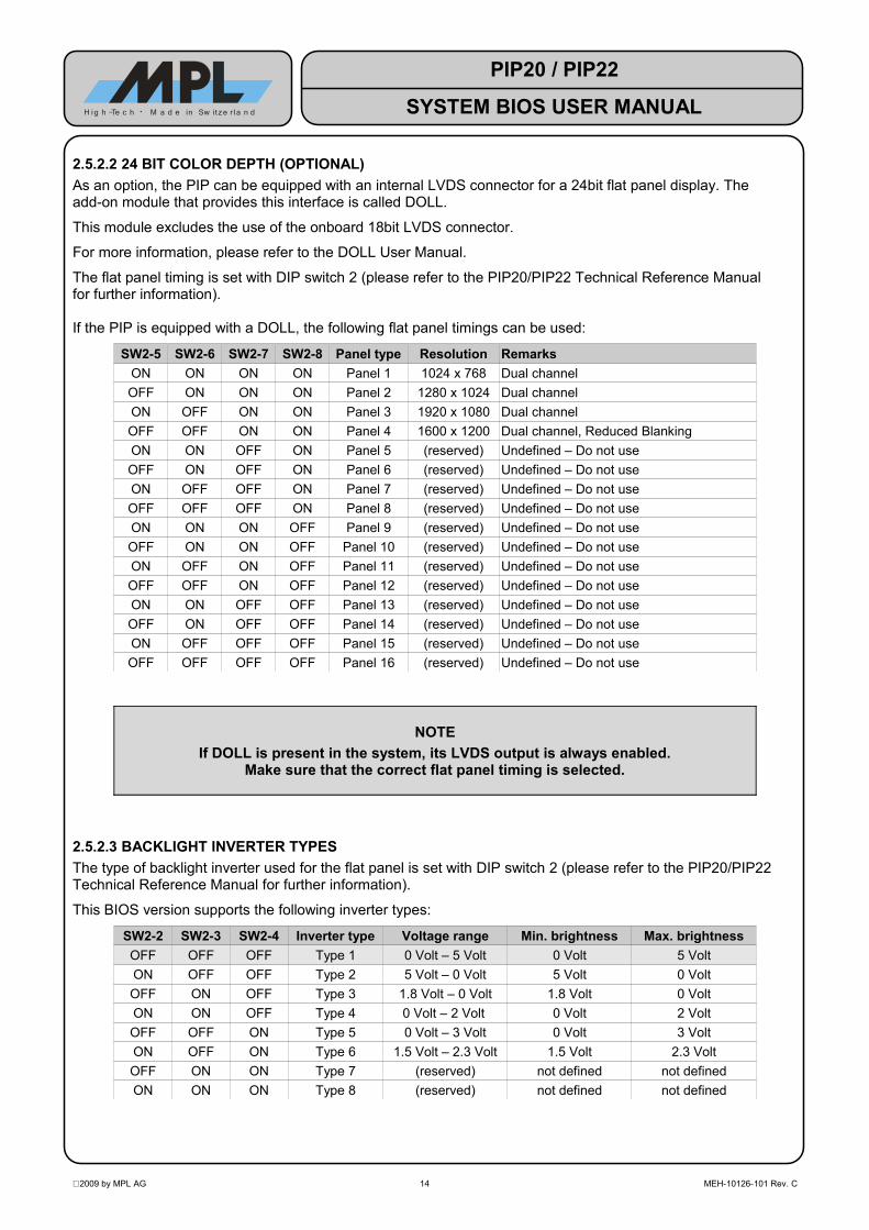
2.5.2.2 24 BIT COLOR DEPTH (OPTIONAL)As an option, the PIP can be equipped with an internal LVDS connector for a 24bit flat panel display. The add-on module that provides this interface is called DOLL.
This module excludes the use of the onboard 18bit LVDS connector.
For more information, please refer to the DOLL User Manual.
The flat panel timing is set with DIP switch 2 (please refer to the PIP20/PIP22 Technical Reference Manual for further information).
If the PIP is equipped with a DOLL, the following flat panel timings can be used:
SW2-5 SW2-6 SW2-7 SW2-8 Panel type Resolution RemarksON ON ON ON Panel 1 1024 x 768 Dual channelOFF ON ON ON Panel 2 1280 x 1024 Dual channelON OFF ON ON Panel 3 1920 x 1080 Dual channelOFF OFF ON ON Panel 4 1600 x 1200 Dual channel, Reduced BlankingON ON OFF ON Panel 5 (reserved) Undefined – Do not useOFF ON OFF ON Panel 6 (reserved) Undefined – Do not useON OFF OFF ON Panel 7 (reserved) Undefined – Do not useOFF OFF OFF ON Panel 8 (reserved) Undefined – Do not useON ON ON OFF Panel 9 (reserved) Undefined – Do not useOFF ON ON OFF Panel 10 (reserved) Undefined – Do not useON OFF ON OFF Panel 11 (reserved) Undefined – Do not useOFF OFF ON OFF Panel 12 (reserved) Undefined – Do not useON ON OFF OFF Panel 13 (reserved) Undefined – Do not useOFF ON OFF OFF Panel 14 (reserved) Undefined – Do not useON OFF OFF OFF Panel 15 (reserved) Undefined – Do not useOFF OFF OFF OFF Panel 16 (reserved) Undefined – Do not use
NOTEIf DOLL is present in the system, its LVDS output is always enabled.
Make sure that the correct flat panel timing is selected.
2.5.2.3 BACKLIGHT INVERTER TYPESThe type of backlight inverter used for the flat panel is set with DIP switch 2 (please refer to the PIP20/PIP22 Technical Reference Manual for further information).
This BIOS version supports the following inverter types:
SW2-2 SW2-3 SW2-4 Inverter type Voltage range Min. brightness Max. brightnessOFF OFF OFF Type 1 0 Volt – 5 Volt 0 Volt 5 VoltON OFF OFF Type 2 5 Volt – 0 Volt 5 Volt 0 VoltOFF ON OFF Type 3 1.8 Volt – 0 Volt 1.8 Volt 0 VoltON ON OFF Type 4 0 Volt – 2 Volt 0 Volt 2 VoltOFF OFF ON Type 5 0 Volt – 3 Volt 0 Volt 3 VoltON OFF ON Type 6 1.5 Volt – 2.3 Volt 1.5 Volt 2.3 VoltOFF ON ON Type 7 (reserved) not defined not definedON ON ON Type 8 (reserved) not defined not defined
2009 by MPL AG 14 MEH-10126-101 Rev. C
PIP20 / PIP22
SYSTEM BIOS USER MANUALH ig h -Te c h • M a d e in Sw itze r l a n d

2.5.2.4 BIOS CONFIGURATIONThe LVDS-related BIOS settings are located in the Video Setup Menu (refer to section 3.15.1).
NOTE: These options are only used if a LVDS panel is connected and properly configured via DIP switches. If the monitor is connected to the DVI-I port of the PIP, these options are inactive and do not affect the display output.
2.5.2.4.1 PANEL BACKLIGHTThis option selects whether the LVDS panel backlight brightness is controlled by BIOS setting or by other means (Hardware up/down switches or application software control).
When set to 'HW/App Control', the backlight can be dimmed by connecting UP and DOWN switches / buttons to Panel Dimming connector J27 (please refer to the Technical Reference Manual for further information).
Panel BacklightHW/App Control Brightness is controlled by hardware or application.
default BIOS Control Brightness is controlled by BIOS setup.
2.5.2.4.2 PANEL BRIGHTNESSThis option controls the brightness level of the panel backlight, if 'Panel Backlight” is set to “BIOS Control'. The brightness can be adjusted in 5% increments.
NOTE: Modifying this option changes the backlight brightness instantly. However, it is still required to write the settings to CMOS when leaving the BIOS setup. Otherwise, the previous brightness setting will be used after leaving the setup.
Panel Brightness (percent)Minimum Minimal brightness level.
5 5% brightness level.10 10% brightness level.... ...... [5% increments]... ...95 95% brightness level.
default 100 100% brightness level.
2.5.2.4.3 PANEL FITTINGThis option controls the fitting of the panel contents.
If the native resolution of a panel does not correspond to the software resolution, the contents is either stretched to fit the native screen resolution or centered, which results in a black frame around the actual screen content.
Panel Fitting is only used in environments without Intel Graphics driver installed (e.g. POST screen, DOS). If an operating system with Intel Graphics driver is started, this setting can be overridden by the driver.
Panel Backlightdefault Default Brightness is controlled by hardware or application.
Center All Modes Both Graphics and Text modes are centered.Stretch All Modes Always fit the screen size.
Stretch Text Modes Text modes are stretched to fit the screen.Stretch Graphics Modes Graphics Modes are stretched to fit the screen.
2009 by MPL AG 15 MEH-10126-101 Rev. C
PIP20 / PIP22
SYSTEM BIOS USER MANUALH ig h -Te c h • M a d e in Sw itze r l a n d
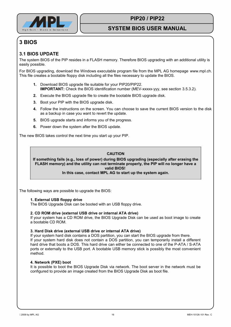
3 BIOS
3.1 BIOS UPDATEThe system BIOS of the PIP resides in a FLASH memory. Therefore BIOS upgrading with an additional utility is easily possible.
For BIOS upgrading, download the Windows executable program file from the MPL AG homepage www.mpl.ch. This file creates a bootable floppy disk including all the files necessary to update the BIOS.
1. Download BIOS upgrade file suitable for your PIP20/PIP22.IMPORTANT: Check the BIOS identification number (MEV-xxxxx-yyy, see section 3.5.3.2).
2. Execute the BIOS upgrade file to create the bootable BIOS upgrade disk.
3. Boot your PIP with the BIOS upgrade disk.
4. Follow the instructions on the screen. You can choose to save the current BIOS version to the disk as a backup in case you want to revert the update.
5. BIOS upgrade starts and informs you of the progress.
6. Power down the system after the BIOS update.
The new BIOS takes control the next time you start up your PIP.
CAUTIONIf something fails (e.g., loss of power) during BIOS upgrading (especially after erasing the FLASH memory) and the utility can not terminate properly, the PIP will no longer have a
valid BIOS! In this case, contact MPL AG to start up the system again.
The following ways are possible to upgrade the BIOS:
1. External USB floppy driveThe BIOS Upgrade Disk can be booted with an USB floppy drive.
2. CD ROM drive (external USB drive or internal ATA drive)If your system has a CD ROM drive, the BIOS Upgrade Disk can be used as boot image to create a bootable CD ROM.
3. Hard Disk drive (external USB drive or internal ATA drive)If your system hard disk contains a DOS partition, you can start the BIOS upgrade from there.If your system hard disk does not contain a DOS partition, you can temporarily install a different hard drive that boots a DOS. This hard drive can either be connected to one of the P-ATA / S-ATA ports or externally to the USB port. A bootable USB memory stick is possibly the most convenient method.
4. Network (PXE) bootIt is possible to boot the BIOS Upgrade Disk via network. The boot server in the network must be configured to provide an image created from the BIOS Upgrade Disk as boot file.
2009 by MPL AG 16 MEH-10126-101 Rev. C
PIP20 / PIP22
SYSTEM BIOS USER MANUALH ig h -Te c h • M a d e in Sw itze r l a n d
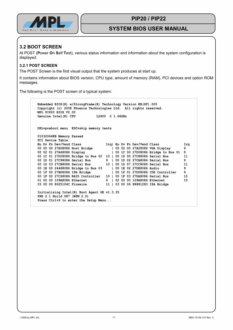
3.2 BOOT SCREENAt POST (Power On Self Test), various status information and information about the system configuration is displayed.
3.2.1 POST SCREENThe POST Screen is the first visual output that the system produces at start up.
It contains information about BIOS version, CPU type, amount of memory (RAM), PCI devices and option ROM messages.
The following is the POST screen of a typical system:
Embedded BIOS(R) w/StrongFrame(R) Technology Version EB(SF).005Copyright (c) 2008 Phoenix Technologies Ltd. All rights reserved.MPL PIP20 BIOS V2.00Genuine Intel(R) CPU L2400 @ 1.66GHz
DEL=preboot menu ESC=skip memory tests01032064KB Memory PassedPCI Device Table.Bu Dv Fn Dev/Vend Class Irq| Bu Dv Fn Dev/Vend Class Irq00 00 00 27A08086 Host Bridge | 00 02 00 27A28086 VGA Display 900 02 01 27A68086 Display | 00 1C 00 27D08086 Bridge to Bus 01 900 1C 01 27D28086 Bridge to Bus 02 10 | 00 1D 00 27C88086 Serial Bus 1100 1D 01 27C98086 Serial Bus 9 | 00 1D 02 27CA8086 Serial Bus 900 1D 03 27CB8086 Serial Bus 10 | 00 1D 07 27CC8086 Serial Bus 1100 1E 00 24488086 Bridge to Bus 03 | 00 1E 02 27DE8086 Audio 900 1F 00 27BD8086 ISA Bridge | 00 1F 01 27DF8086 IDE Controller 900 1F 02 27C68086 RAID Controller 10 | 00 1F 03 27DA8086 Serial Bus 1001 00 00 109A8086 Ethernet 9 | 02 00 00 109A8086 Ethernet 1003 00 00 8025104C Firewire 11 | 03 00 06 88881283 ISA BridgeInitializing Intel(R) Boot Agent GE v1.3.35PXE 2.1 Build 087 (WfM 2.0)Press Ctrl+S to enter the Setup Menu...
2009 by MPL AG 17 MEH-10126-101 Rev. C
PIP20 / PIP22
SYSTEM BIOS USER MANUALH ig h -Te c h • M a d e in Sw itze r l a n d

3.2.2 PCI DEVICESAt POST, the PCI devices installed in the system are listed. The figure below shows the typical PCI devices present on the PIP board.
Depending on BIOS settings and installed options, the actual PCI table may differ slightly from the example below.
NOTE: All additional PC/104+ and/or PCI devices installed in the system will appear on bus 03 and above.
PCI Device Table.Bu Dv Fn Dev/Vend Class Irq| Bu Dv Fn Dev/Vend Class Irq00 00 00 27A08086 Host Bridge | 00 02 00 27A28086 VGA Display 900 02 01 27A68086 Display | 00 1C 00 27D08086 Bridge to Bus 01 900 1C 01 27D28086 Bridge to Bus 02 10 | 00 1D 00 27C88086 Serial Bus 1100 1D 01 27C98086 Serial Bus 9 | 00 1D 02 27CA8086 Serial Bus 900 1D 03 27CB8086 Serial Bus 10 | 00 1D 07 27CC8086 Serial Bus 1100 1E 00 24488086 Bridge to Bus 03 | 00 1E 02 27DE8086 Audio 900 1F 00 27BD8086 ISA Bridge | 00 1F 01 27DF8086 IDE Controller 900 1F 02 27C68086 RAID Controller 10 | 00 1F 03 27DA8086 Serial Bus 1001 00 00 109A8086 Ethernet 9 | 02 00 00 109A8086 Ethernet 1003 00 00 8025104C Firewire 11 | 03 00 06 88881283 ISA Bridge
3.2.3 POST INTERVENTIONThe following table is an overview of the keys that invoke functions at POST.
Key Action
[B] or[CTRL] + [B]
Enter BBS Boot Action menu (see section 3.4 for details).
[DEL] or[C] or
[CTRL] + [C]Enter BIOS Setup.
[D] or[CTRL] + [D]
Skip disk drive detection.
[ESC] Skip memory testing.
2009 by MPL AG 18 MEH-10126-101 Rev. C
PIP20 / PIP22
SYSTEM BIOS USER MANUALH ig h -Te c h • M a d e in Sw itze r l a n d

3.3 SETUP SCREEN STRUCTURE
3.3.1 INTRODUCTIONThe BIOS setup screen is divided into several menus. Menus contain setup options and fields that fall into the same context. For example, the 'Boot' menu contains settings that deal with configuring the system's boot order.
On the top of the screen, all available menus are listed. Note the '<' and '>' symbols which can appear at either end of the menu line to indicate that the list of menus continues in that direction.
3.3.2 MENUSEach menu is divided into different sections.The left side of the screen contains configuration options/fields (the “BIOS settings”) and/or displays read-only information fields. Related items are grouped (see the screenshot below, for example the 'Console Redirection' items).
The currently selected field (the cursor position) is highlighted.
The right side of the screen contains a help area which provides instant help related to the selected option.
The following screenshot shows the main parts of a typical setup screen view (the 'Features' menu is selected):
System Configuration Utility Main Exit Boot POST PnP SIO Features Firmbase Misc >+--------------------------------------------------------+---------------------+| BIOS Feature Configuration |Enable Advanced || -------------------------------------------------------|Configuration and || Interrupt Processing [Use APIC] |Power Interface || MP Tables (non-ACPI OSes) [Enabled] |(ACPI) support. DO || ACPI [Enabled] |NOT CHANGE AFTER OS || POST Memory Manager [Enabled] |INSTALL. || System Management BIOS [Enabled] | || SMBUS API [Disabled] | || Splash Screen [Disabled] | || | || Console Redirection | || -------------------------------------------------------| || Use Console Assignments Below [Never] | || POST Console [COM1] | || Preboot Console [COM1] | || Debugger Console [COM1] | || | || CPU Configuration | || -------------------------------------------------------| || P7 Geyserville/Speedstep [Enabled] | |+--------------------------------------------------------+---------------------+Embedded BIOS(R) w/StrongFrame(R) Technology - (c)2008 Phoenix Technologies Ltd
2009 by MPL AG 19 MEH-10126-101 Rev. C
PIP20 / PIP22
SYSTEM BIOS USER MANUALH ig h -Te c h • M a d e in Sw itze r l a n d
Selected menu
Menus
Help area
Options (Fields)
Selected field
(Cursor position)
Additional menus follow

3.3.3 NAVIGATIONThe following table is an overview of the keys used to navigate through the setup menu and modify the settings.
Key Action[LEFT] Go to next menu.
[RIGHT] Go to previous menu.[DOWN] Move cursor one line down, scrolling the window as necessary.
[UP] Move cursor one line up, scrolling the window as necessary.[TAB] Move cursor down, to the next configurable field.
[SHIFT] + [TAB] Move cursor up, to the previous configurable field.
[HOME] Move cursor to first configurable field of the current menu, scrolling the window as necessary.
[END] Move cursor to last configurable field of the current menu, scrolling the window as necessary.
[ESC] Invoke 'Exit Setup Without Saving Changes' command. A confirmation dialog appears.
[SPACE]Toggle an Enable/Disable field.Go to next value of a multiple choice field.Increase a numeric field's value.
[+]Toggle an Enable / Disable field.Go to next value of a multiple choice field.Increase a numeric field's value.
[–]Toggle an Enable/Disable field.Go to previous value of a multiple choice field.Decrease a numeric field's value.
[BACKSPACE] Reset an Enable/Disable or multiple choice field.Back-up in numeric fields .
[0] – [9] Used to enter numeric values, e.g. RTC time.
2009 by MPL AG 20 MEH-10126-101 Rev. C
PIP20 / PIP22
SYSTEM BIOS USER MANUALH ig h -Te c h • M a d e in Sw itze r l a n d

3.4 BOOT ACTION MENUThe Boot Action Menu can be invoked by pressing the 'B' key at POST. It also appears at the end of POST in the event that the BIOS does not find a bootable device.
The Boot Action Menu can be used to boot from a different device, without having to change the Boot Order in the BIOS setup.
The boot device can be selected by using the UP and DOWN arrow keys. Pressing ENTER executes the boot command. If booting the device was not successful, the system returns to the Boot Action Menu.
The Boot Action Menu lists all possible boot sources. This does not mean that all sources are ready to be booted from. Some may not work without further initialization.
The following shows a typical Boot Action Menu:
Boot Action Menu+--------------------------------------------------------+---------------------+| USB Floppy |Press enter to select|| USB Hard Drive |a boot action or || USB CDROM Drive |[ESC] to exit. || IDE 0/Pri Master | || IDE 1/Pri Slave | || SATA Drive 0 | || SATA Drive 2 | || Onboard RAID | || PXE Network Boot, Onboard LAN 1 | || PXE Network Boot, Onboard LAN 2 | || PC/104+ Slot 1 | || PC/104+ Slot 2 | || PC/104+ Slot 3 | || PC/104+ Slot 4 | || Enter BIOS Setup Screen | || Reboot System | || | || | || | || | |+--------------------------------------------------------+---------------------+Embedded BIOS(R) w/StrongFrame(R) Technology - (c)2008 Phoenix Technologies Ltd
2009 by MPL AG 21 MEH-10126-101 Rev. C
PIP20 / PIP22
SYSTEM BIOS USER MANUALH ig h -Te c h • M a d e in Sw itze r l a n d

3.5 MAIN SETUP MENU System Configuration Utility Main Exit Boot POST PnP SIO Features Firmbase Misc >+--------------------------------------------------------+---------------------+| System Summary |Use TAB to switch || -------------------------------------------------------|between month, day || Phoenix[R] System BIOS |and year. Use digits|| BIOS Version EB(SF).005 |and BKSP to change || BIOS Build Date 10/29/09 |field. || System BIOS Size 128KB | || CPM/CSPM/BPM Modules P7C7, 945GM, PIP20 | || StrongFrame(R) Technology, Firmbase(R) Technology | || | || Processor (CPU) | || Genuine Intel(R) CPU L2400 @ 1.66GHz | || Processor Count 2 | || | || System Memory (RAM) | || Low Memory (KB) 626 | || Extended Memory (KB) 3128128 | || | || Real Time Clock (RTC) | || RTC Date [04/15/2009] | || RTC Time [12:15:33] | |+--------------------------------------------------------+---------------------+Embedded BIOS(R) w/StrongFrame(R) Technology - (c)2008 Phoenix Technologies Ltd
3.5.1 SYSTEM SUMMARYThis section contains detailed information about the system, such as BIOS details, processor information and system memory information.
3.5.2 REAL TIME CLOCK (RTC)The system's time and date are set here.
NOTE: Unlike other BIOS settings, changes to the time and/or date are applied immediately. It is not necessary to save the BIOS settings if just the time and/or date have been changed.
RTC Date notation is [mm/dd/yyyy] (mm = Month, dd = Day, yyyy = Year)RTC Time notation is [hh:mm:ss] in 24h format (hh = Hours, mm = Minutes, ss = Seconds)
The default values are as follows:RTC Date: equals BIOS Build DateRTC Time: 00:00:00
2009 by MPL AG 22 MEH-10126-101 Rev. C
PIP20 / PIP22
SYSTEM BIOS USER MANUALH ig h -Te c h • M a d e in Sw itze r l a n d
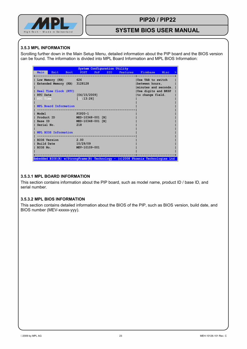
3.5.3 MPL INFORMATIONScrolling further down in the Main Setup Menu, detailed information about the PIP board and the BIOS version can be found. The information is divided into MPL Board Information and MPL BIOS Information:
System Configuration Utility Main Exit Boot POST PnP SIO Features Firmbase Misc >+--------------------------------------------------------+---------------------+| Low Memory (KB) 626 |Use TAB to switch || Extended Memory (KB) 3128128 |between hours, || |minutes and seconds. || Real Time Clock (RTC) |Use digits and BKSP || RTC Date [04/15/2009] |to change field. || RTC Time [11:13:26] | || | || MPL Board Information | || -------------------------------------------------------| || Model PIP20-1 | || Product ID MED-10348-001 [B] | || Base ID MED-10348-001 [B] | || Serial No. 218 | || | || MPL BIOS Information | || -------------------------------------------------------| || BIOS Version 2.00 | || Build Date 10/29/09 | || BIOS No. MEV-10109-001 | || | |+--------------------------------------------------------+---------------------+Embedded BIOS(R) w/StrongFrame(R) Technology - (c)2008 Phoenix Technologies Ltd
3.5.3.1 MPL BOARD INFORMATIONThis section contains information about the PIP board, such as model name, product ID / base ID, and serial number.
3.5.3.2 MPL BIOS INFORMATIONThis section contains detailed information about the BIOS of the PIP, such as BIOS version, build date, and BIOS number (MEV-xxxxx-yyy).
2009 by MPL AG 23 MEH-10126-101 Rev. C
PIP20 / PIP22
SYSTEM BIOS USER MANUALH ig h -Te c h • M a d e in Sw itze r l a n d

3.6 EXIT SETUP MENU
System Configuration Utility Main Exit Boot POST PnP SIO Features Firmbase Misc >+--------------------------------------------------------+---------------------+| Save, Restore, and Exit Setup |Press ENTER to save || -------------------------------------------------------|changes and reboot || Save Settings and Restart [Enter] |system. || | || Exit Setup Without Saving Changes [Enter] | || | || Reload Factory-Defaults and Restart [Enter] | || | || | || Save, Restore, and Exit Setup – Use Permanent Storage | || -------------------------------------------------------| || Save Settings, Store to Flash and Restart [Enter] | || | || Load Settings from Flash and Restart [Enter] | || | || Clear Settings in Flash [Enter] | || | || | || | || | |+--------------------------------------------------------+---------------------+Embedded BIOS(R) w/StrongFrame(R) Technology - (c)2008 Phoenix Technologies Ltd
The Exit Setup Menu allows the user to manage the BIOS settings. BIOS settings are typically stored in the battery-backed CMOS RAM. In addition, they can also be stored to Flash (Permanent Storage).
3.6.1 SAVE, RESTORE AND EXIT SETUP
3.6.1.1 SAVE SETTINGS AND RESTARTSaves the current settings to CMOS and reboots the system.
After pressing <ENTER>, the following confirmation dialog appears:
| Reload Factory-Defaults and Restart [Enter] | || | || +------------------------------+ | || Save, Restore, and Exi| Save, exit and reboot? (Y/N) | | || ----------------------+------------------------------+-| || Save Settings, Store to Flash and Restart [Enter] | || | |
Pressing <Y> saves the settings to CMOS and reboots the system.Pressing <N> aborts the action and returns to the Exit Setup Menu.
2009 by MPL AG 24 MEH-10126-101 Rev. C
PIP20 / PIP22
SYSTEM BIOS USER MANUALH ig h -Te c h • M a d e in Sw itze r l a n d

3.6.1.2 EXIT SETUP WITHOUT SAVING CHANGESDiscards any changes to the settings and exits BIOS setup.
After pressing <ENTER>, the following confirmation dialog appears:
| Reload Factory-Defaults and Restart [Enter] | || | || +----------------------------+ | || Save, Restore, and Exit| Exit without saving? (Y/N) | | || -----------------------+----------------------------+--| || Save Settings, Store to Flash and Restart [Enter] | || | |
Pressing <Y> leaves the setup without saving any changes.Pressing <N> aborts the action and returns to the Exit Setup Menu.
3.6.1.3 RELOAD FACTORY-DEFAULTS AND RESTARTLoads the factory default settings and reboots the system.
NOTE: The time and date values remain unaffected when the factory defaults are loaded.
After pressing <ENTER>, the following confirmation dialog appears:
| Reload Factory-Defaults and Restart [Enter] | || | || +-------------------------------------------+ || Save, Restore, | Reset to default values and reboot? (Y/N) | || ---------------+-------------------------------------------+ || Save Settings, Store to Flash and Restart [Enter] | || | |
Pressing <Y> loads the factory default BIOS settings and reboots the system.Pressing <N> aborts the action and returns to the Exit Setup Menu.
2009 by MPL AG 25 MEH-10126-101 Rev. C
PIP20 / PIP22
SYSTEM BIOS USER MANUALH ig h -Te c h • M a d e in Sw itze r l a n d

3.6.2 SAVE, RESTORE AND EXIT SETUP – USE PERMANENT STORAGEThese options control the storing of CMOS settings in both CMOS RAM and Flash.
Both CMOS RAM and Flash are non-volatile memories. They retain the settings when the system is powered down.
The difference between the two technologies is that Flash does not need any power source to retain its contents whereas CMOS RAM must be powered by the CMOS battery. If the CMOS battery is dead, removed or disabled, the CMOS RAM will be corrupt, and the BIOS settings are lost. The contents of the Flash however is not affected by such an event.
The contents of the CMOS RAM is checked at POST. If the BIOS detects that the CMOS RAM is corrupt, it checks whether the Flash contains a valid set of CMOS settings. If this is the case, the BIOS loads these settings into the CMOS RAM. If not, the BIOS loads the factory default values.
NOTE: The time and date values are not stored in the Flash. Whenever the CMOS settings are loaded from the Flash due to a corrupt CMOS RAM, the date will be reset to the BIOS build date and the time will be reset to 00:00:00.
3.6.2.1 SAVE SETTINGS, STORE TO FLASH AND RESTARTSaves the current settings to CMOS and to Flash and reboots the system.
After pressing <ENTER>, the following confirmation dialog appears:
| Reload Factory-Defaults and Restart [Enter] | || | || +----------------------------------------------+ || Save, Restore,| Save, store to Flash, exit and reboot? (Y/N) | || --------------+----------------------------------------------+ || Save Settings, Store to Flash and Restart [Enter] | || | |
Pressing <Y> saves the settings to CMOS and Flash and reboots the system.Pressing <N> aborts the action and returns to the Exit Setup Menu.
3.6.2.2 LOAD SETTINGS FROM FLASH AND RESTARTLoads the settings from Flash into CMOS.
After pressing <ENTER>, the following confirmation dialog appears:
| Reload Factory-Defaults and Restart [Enter] | || | || +--------------------------------------------+ || Save, Restore, | Load settings from Flash and reboot? (Y/N) | || ---------------+--------------------------------------------+ || Save Settings, Store to Flash and Restart [Enter] | || | |
Pressing <Y> loads the settings from Flash to CMOS and reboots the system.Pressing <N> aborts the action and returns to the Exit Setup Menu.
If the Flash does not contain valid BIOS settings, the command will not be executed. The following message indicates this:
| Reload Factory-Defaults and Restart [Enter] | || | || +--------------------------------------------------------------------+ || Sav| No valid settings in Flash! Load aborted. Press any key to return. | || ---+--------------------------------------------------------------------+ || Save Settings, Store to Flash and Restart [Enter] | || | |
2009 by MPL AG 26 MEH-10126-101 Rev. C
PIP20 / PIP22
SYSTEM BIOS USER MANUALH ig h -Te c h • M a d e in Sw itze r l a n d

If loading the settings from Flash failed, the following message appears:
| Reload Factory-Defaults and Restart [Enter] | || | || +---------------------------------------------------------+ || Save, Re| ERROR: Load from Flash failed! Press any key to return. | || --------+---------------------------------------------------------+ || Save Settings, Store to Flash and Restart [Enter] | || | |
3.6.2.3 CLEAR SETTINGS IN FLASHClears the part of the Flash that holds CMOS settings.
After pressing <ENTER>, the following confirmation dialog appears:
| Reload Factory-Defaults and Restart [Enter] | || | || +----------------------------------+ || Save, Restore, and E| Clear settings from Flash? (Y/N) | || --------------------+----------------------------------+ || Save Settings, Store to Flash and Restart [Enter] | || | |
Pressing <Y> erases the settings from the Flash and returns to the Exit Setup Menu.Pressing <N> aborts the action and returns to the Exit Setup Menu.
The following message indicates that the Flash has been successfully cleared:
| Reload Factory-Defaults and Restart [Enter] | || | || +---------------------------------------------------------+ || Save, Re| Settings cleared successfully. Press any key to return. | || --------+---------------------------------------------------------+ || Save Settings, Store to Flash and Restart [Enter] | || | |
If the Flash does not contain valid BIOS settings, the command will not be executed. The following message indicates this:
| Reload Factory-Defaults and Restart [Enter] | || | || +---------------------------------------------------------------------+ || Sa| No valid settings in Flash! Clear aborted. Press any key to return. | || --+---------------------------------------------------------------------+ || Save Settings, Store to Flash and Restart [Enter] | || | |
If clearing the settings failed, the following message appears:
| Reload Factory-Defaults and Restart [Enter] | || | || +-----------------------------------------------------------------+ || Save| ERROR: Clear settings in Flash failed! Press any key to return. | || ----+-----------------------------------------------------------------+ || Save Settings, Store to Flash and Restart [Enter] | || | |
2009 by MPL AG 27 MEH-10126-101 Rev. C
PIP20 / PIP22
SYSTEM BIOS USER MANUALH ig h -Te c h • M a d e in Sw itze r l a n d
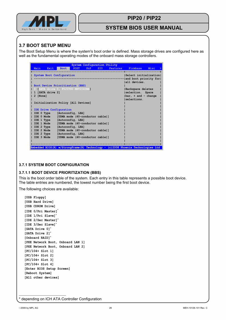
3.7 BOOT SETUP MENUThe Boot Setup Menu is where the system's boot order is defined. Mass storage drives are configured here as well as the fundamental operating modes of the onboard mass storage controllers.
System Configuration Utility Main Exit Boot POST PnP SIO Features Firmbase Misc >+--------------------------------------------------------+---------------------+| System Boot Configuration |Select initialization|| -------------------------------------------------------|and boot priority for|| |all devices. || Boot Device Prioritization (BBS) | || 0 [SATA drive 0, FUJITSU MHT2040BH] |Backspace deletes || 1 [SATA drive 2] |selection. Space || 2 [None] |bar, + and - change || |selections. || Initialization Policy [All Devices] | || | || IDE Drive Configuration | || IDE 0 Type [Autoconfig, LBA] | || IDE 0 Mode [UDMA mode (40-conductor cable)] | || IDE 1 Type [Autoconfig, LBA] | || IDE 1 Mode [UDMA mode (40-conductor cable)] | || IDE 2 Type [Autoconfig, LBA] | || IDE 2 Mode [UDMA mode (40-conductor cable)] | || IDE 2 Type [Autoconfig, LBA] | || IDE 3 Mode [UDMA mode (40-conductor cable)] | || | |+--------------------------------------------------------+---------------------+Embedded BIOS(R) w/StrongFrame(R) Technology - (c)2008 Phoenix Technologies Ltd
3.7.1 SYSTEM BOOT CONFIGURATION
3.7.1.1 BOOT DEVICE PRIORITIZATION (BBS)This is the boot order table of the system. Each entry in this table represents a possible boot device. The table entries are numbered, the lowest number being the first boot device.
The following choices are available:
[USB Floppy][USB Hard Drive][USB CDROM Drive][IDE 0/Pri Master]*
[IDE 1/Pri Slave]*
[IDE 2/Sec Master]*
[IDE 3/Sec Slave]*
[SATA Drive 0]*
[SATA Drive 2]*
[Onboard RAID]*
[PXE Network Boot, Onboard LAN 1][PXE Network Boot, Onboard LAN 2][PC/104+ Slot 1][PC/104+ Slot 2][PC/104+ Slot 3][PC/104+ Slot 4][Enter BIOS Setup Screen][Reboot System][All other devices]
* depending on ICH ATA Controller Configuration
2009 by MPL AG 28 MEH-10126-101 Rev. C
PIP20 / PIP22
SYSTEM BIOS USER MANUALH ig h -Te c h • M a d e in Sw itze r l a n d

Depending on the BIOS configuration, some items may be missing. For example, USB devices are only listed if both 'Firmbase Environment' and 'USB Boot' are enabled (see to section 3.12).
The above list shows the generic device names. When a device has been detected successfully, its name will either replace the generic name or will be added to it, for example:
[USB Hard Drive] → [takeMS USB EasyII USB Device][SATA Drive 0] → [SATA Drive 0, FUJITSU MHT2040BH][Onboard RAID] → [Intel Volume0 card in Onboard RAID]
NOTE: For pre-OS and legacy environments (e.g. DOS), all devices that need to be accessible must be added to the Boot Device Prioritization list. For example, if a USB Floppy drive is used to load a Mass Storage driver (e.g. RAID) during Windows setup, [USB Floppy] must be one of the entries in the table (preferrably the last one if booting from the floppy drive is not required).
3.7.1.2 INITIALIZATION POLICYThis option controls how devices are initialized at POST. The execution of Option ROMs (such as RAID, Ethernet PXE) can be controlled with this option. For example, if PXE Network Boot is not selected in in the Boot Device Prioritization menu, the PXE Option ROM will not be executed, thus leaving room for other Option ROMs that might be present in the system to execute (e.g those on add-on cards).
Initialization Policy
Boot Devices Only Only devices that are listed in the Boot Device Prioritization (BBS) menu are initialized.
default All Devices All devices are initialized.
2009 by MPL AG 29 MEH-10126-101 Rev. C
PIP20 / PIP22
SYSTEM BIOS USER MANUALH ig h -Te c h • M a d e in Sw itze r l a n d

3.7.1.3 IDE DRIVE CONFIGURATIONThese settings configure PATA devices.They are numbered 0 to 4 (Primary Master to Secondary Slave). The relationship between physical ports and BIOS names depends on the ICH ATA Controller configuration (see section 3.7.2).
Normally, these settings do not need to be changed, except when the default values do not work properly for a specific hard disk drive.
IDE x TypeNot installed No drive installed.
default Autoconfig
The 'Autoconfig' type performs the same query as 'Physical' (see below), but follows up by analyzing sector 0 and determining the geometry based on the MBR.NOTE: If the drive is not properly detected with this setting, use
'Autoconfig, LBA' instead.
Autoconfig, PhysicalThe 'Physical' type queries the drive's geometry from the controller and uses it without further translation, if the drive is smaller than 528MB.If the drive is larger than 528MB, LBA translation is used.
Autoconfig, LBA The 'LBA' type always translates the drive's geometry according to the LBA standard, regardless of the drive's size.
Autoconfig, Phoenix The 'Phoenix' type queries the drive's geometry from the controller and translates it according to the Phoenix CHS convention.
IDE x ModeFastest supported
mde Configures the drive for the fastest supported mode.
PIO mode Configures the drive for PIO mode, ignoring any reported support for multi-word DMA or UDMA modes.
Multi-word DMA mode Configures the drive for multi-word DMA mode, ignoring any reported support for UDMA modes.
default UDMA mode (40-concuctor cable)
Configures the drive for UDMA mode, limited to the maximum mode allowed with a 40-conductor cable (UDMA mode 2, equals UDMA/33).
UDMA mode (80-conductor cable)
Configures the drive for UDMA mode, allowing modes acheivable with a 80-conductor cable.NOTE: The 44-pin IDE connector does not support a 80-conductor
cable.
2009 by MPL AG 30 MEH-10126-101 Rev. C
PIP20 / PIP22
SYSTEM BIOS USER MANUALH ig h -Te c h • M a d e in Sw itze r l a n d

3.7.2 ICH ATA CONTROLLER CONFIGURATIONThe Southbridge of the PIP contains a SATA and a PATA controller. These settings configure the operating modes of the controllers.
3.7.2.1 SATA CONTROLLERThis option controls the operating mode of the SATA controller.
SATA ControllerDisabled The SATA controller is disabled.
Compatible Mode SATA controller operates in Compatible Mode.This mode is supported by all operating systems.
default Native Mode
SATA controller operates in Native Mode.
NOTE: This mode is only supported by newer operating systems (e.g. Windows XP).
Relationships between physical ports and BIOS names are as follows:PIP SATA0 port = 'SATA drive 0'PIP SATA1 port = 'SATA drive 2'
AHCI Mode
SATA controller operates in AHCI mode.
NOTE: This mode is only supported by newer operating systems (e.g. Windows XP) and may require special drivers for the operating system!
Relationships between physical ports and BIOS names are as follows:PIP SATA0 port = 'SATA drive 0'PIP SATA1 port = 'SATA drive 2'
RAID Mode
SATA controller operates in RAID mode. The RAID Option ROM will be activated to support booting from the RAID.
NOTE: This mode is only supported by newer operating systems (e.g. Windows XP) and may require special drivers for the operating system!
Relationships between physical ports and BIOS names are as follows:PIP SATA0 port = 'SATA drive 0'PIP SATA1 port = 'SATA drive 2'
2009 by MPL AG 31 MEH-10126-101 Rev. C
PIP20 / PIP22
SYSTEM BIOS USER MANUALH ig h -Te c h • M a d e in Sw itze r l a n d

3.7.2.1.1 RAIDWhen the SATA controller is set to RAID mode, the RAID Option ROM will be activated.In this mode, two SATA disks are required to create RAID-0 (Striping) or RAID-1 (Mirroring) sets.The basic creation of RAID sets is done in the Configuration Utility of the RAID Option ROM.
The following screenshot shows the boot messages with a RAID1 set:
Intel(R) Matrix Storage Manager option ROM v5.7.0.1011 ICH7MRCopyright(C) 2003-06 Intel Corporation. All Rights Reserved. RAID Volumes: ID Name Level Strip Size Status Bootable 0 Volume0 RAID1(Mirror) N/A 10.0GB Normal Yes Physical Disks: Port Drive Model Serial # Size Type/Status (Vol ID) 0 FUJITSU MHT2040B NR21T5B27G2J 37.3GB Member Disk(0) 2 FUJITSU MHT2040B NR34T4E56G45 37.3GB Member Disk(0)Press <CTRL+I> to enter Configuration Utility...
The RAID Configuration Utility can be started by pressing <CTRL+I>. This utility allows the creation of RAID sets so that the operating system can be installed onto that set.
Intel(R) Matrix Storage Manager option ROM v5.7.0.1011 ICH7MR Copyright(C) 2003-06 Intel Corporation. All Rights Reserved.+---------------------------------[ MAIN MENU ]--------------------------------+| 1. Create RAID Volume || 2. Delete RAID Volume || 3. Reset Disks to Non-RAID || 4. Exit |+------------------------------------------------------------------------------++--------------------------[ DISK/VOLUME INFORMATION ]-------------------------+| RAID Volumes: || ID Name Level Strip Size Status Bootable || 0 Volume0 RAID1(Mirror) N/A 10.0GB Normal Yes || || Physical Disks: || Port Drive Model Serial # Size Type/Status (Vol ID) || 0 FUJITSU MHT2040B NR21T5B27G2J 37.3GB Member Disk(0) || 2 FUJITSU MHT2040B NR34T4E56G45 37.3GB Member Disk(0) || || || || || || | +------------------------------------------------------------------------------+ [↑↓]-Select [ESC]-Exit [ENTER]-Select Menu
2009 by MPL AG 32 MEH-10126-101 Rev. C
PIP20 / PIP22
SYSTEM BIOS USER MANUALH ig h -Te c h • M a d e in Sw itze r l a n d

3.7.2.1.2 COMBINED MODEIf SATA Controller is set to 'Compatible Mode', this option appears.
Combined ModeDisabled Combined Mode is disabled.
default P0/P2=Pri, PATA=Sec
The SATA controller controls both SATA ports and the PATA port.
NOTE: This setting disables the 'PATA Controller' option.
Relationships between physical ports and BIOS names are as follows:SATA0 port = 'IDE 0/Pri Master'SATA1 port = 'IDE 1/Pri Slave'PATA Master = 'IDE 2/Sec Master'PATA Slave = 'IDE 3/Sec Slave'
3.7.2.2 PATA CONTROLLERThis option controls the operating mode of the PATA controller.
NOTE: If 'Combined Mode is set to 'P0/P2=Pri, PATA=Sec', this option is not available.
PATA ControllerDisabled The PATA controller is disabled.
default Compatible Mode
PATA Controller operates in Compatible Mode.This mode is supported by all operating systems.
Relationships between physical ports and BIOS names are as follows:PATA Master = 'IDE 0/Pri Master'PATA Slave = 'IDE 1/Pri Slave'
Native Mode
SATA controller operates in Native Mode.NOTE: This mode is only supported by newer operating systems (e.g.
Windows XP).
Relationships between physical ports and BIOS names are as follows:PATA Master = 'IDE 0/Pri Master'PATA Slave = 'IDE 1/Pri Slave'
2009 by MPL AG 33 MEH-10126-101 Rev. C
PIP20 / PIP22
SYSTEM BIOS USER MANUALH ig h -Te c h • M a d e in Sw itze r l a n d

3.8 POST SETUP MENU System Configuration Utility Main Exit Boot POST PnP SIO Features Firmbase Misc >+--------------------------------------------------------+---------------------+| POST Memory Tests |Enable basic memory || -------------------------------------------------------|confidence test below|| Low Memory Standard Test [Enabled] |1MB during POST. || Low Memory Exhaustive Test [Disabled] | || High Memory Standard Test [Disabled] | || High Memory Exhaustive Test [Disabled] | || Click During Memory Test [Enabled] | || Clear Memory During Test [Disabled] | || | || POST Error Control | || -------------------------------------------------------| || Pause on POST Errors [Enabled] | || | || POST User Interface | || -------------------------------------------------------| || POST Display Messages [Enabled] | || POST Operator Prompt [Enabled] | || POST Display PCI Devices [Enabled] | || POST Display PnP Devices [Enabled] | || | |+--------------------------------------------------------+---------------------+Embedded BIOS(R) w/StrongFrame(R) Technology - (c)2008 Phoenix Technologies Ltd
3.8.1 POST MEMORY TESTS
3.8.1.1 LOW MEMORY STANDARD TESTThis option enables or disables standard memory tests below 1MB.
Low Memory Standard TestDisabled Do not test memory below 1MB at POST.
default Enabled Test memory below 1MB at POST.
3.8.1.2 LOW MEMORY EXHAUSTIVE TESTThis option enables or disables exhaustive memory tests below 1MB.
Low Memory Exhaustive Testdefault Disabled Do not exhaustively test memory below 1MB at POST.
Enabled Exhaustively test memory below 1MB at POST.
3.8.1.3 HIGH MEMORY STANDARD TESTThis option enables or disables standard memory tests above 1MB.
High Memory Standard Testdefault Disabled Do not test memory above 1MB at POST.
Enabled Test memory above 1MB at POST.
3.8.1.4 HIGH MEMORY EXHAUSTIVE TESTThis option enables or disables exhaustive memory tests above 1MB.
High Memory Standard Testdefault Disabled Do not exhaustively test memory above 1MB at POST.
Enabled Exhaustively test memory above 1MB at POST.
2009 by MPL AG 34 MEH-10126-101 Rev. C
PIP20 / PIP22
SYSTEM BIOS USER MANUALH ig h -Te c h • M a d e in Sw itze r l a n d

3.8.1.5 CLICK DURING MEMORY TESTThis option enables or disables clicking of the speaker (if equipped) during memory test.
Click During Memory Testdefault Disabled Do not click during memory test.
Enabled Click during memory test.
3.8.1.6 CLEAR MEMORY DURING TESTThis option enables or disables clearing of the memory during memory count-up.When enabled, '0' are written to every memory location.This option is provided for compatibility with legacy software that may rely on the memory being cleared after POST.
Clear Memory During Testdefault Disabled Do not clear memory during test.
Enabled Clear memory during test.
3.8.2 POST ERROR CONTROL
3.8.2.1 PAUSE ON POST ERRORSThis option enables or disables pause when errors are detected during POST. This gives the user the possibility to take an action (e.g. enter the BIOS setup) whenever an error occurs.
Pause on POST ErrorsDisabled Do not pause on POST errors.
default Enabled Pause on POST errors.
3.8.3 POST USER INTERFACE
3.8.3.1 POST DISPLAY MESSAGESThis option enables or disables messages during POST (i.e. PCI device listing).
POST Display MessagesDisabled Do not display POST messages.
default Enabled Display POST messages.
3.8.3.2 POST OPERATOR PROMPTThis option enables or disables operator prompt during POST (i.e. '<DEL>=preboot menu').
POST Operator PromptDisabled Do not display operator prompt.
default Enabled Display operator prompt.
2009 by MPL AG 35 MEH-10126-101 Rev. C
PIP20 / PIP22
SYSTEM BIOS USER MANUALH ig h -Te c h • M a d e in Sw itze r l a n d
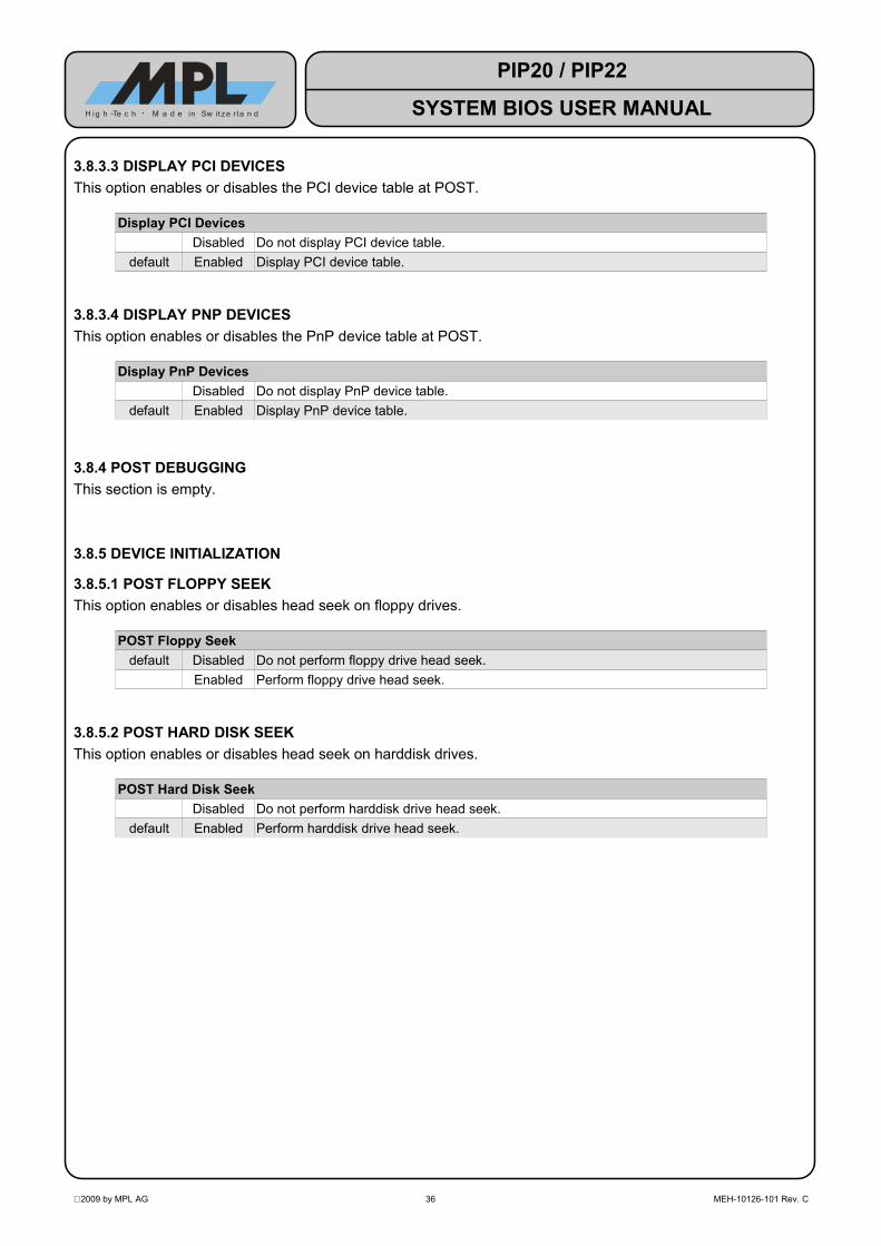
3.8.3.3 DISPLAY PCI DEVICESThis option enables or disables the PCI device table at POST.
Display PCI DevicesDisabled Do not display PCI device table.
default Enabled Display PCI device table.
3.8.3.4 DISPLAY PNP DEVICESThis option enables or disables the PnP device table at POST.
Display PnP DevicesDisabled Do not display PnP device table.
default Enabled Display PnP device table.
3.8.4 POST DEBUGGINGThis section is empty.
3.8.5 DEVICE INITIALIZATION
3.8.5.1 POST FLOPPY SEEKThis option enables or disables head seek on floppy drives.
POST Floppy Seekdefault Disabled Do not perform floppy drive head seek.
Enabled Perform floppy drive head seek.
3.8.5.2 POST HARD DISK SEEKThis option enables or disables head seek on harddisk drives.
POST Hard Disk SeekDisabled Do not perform harddisk drive head seek.
default Enabled Perform harddisk drive head seek.
2009 by MPL AG 36 MEH-10126-101 Rev. C
PIP20 / PIP22
SYSTEM BIOS USER MANUALH ig h -Te c h • M a d e in Sw itze r l a n d

3.9 PNP SETUP MENU System Configuration Utility Main Exit Boot POST PnP SIO Features Firmbase Misc >+--------------------------------------------------------+---------------------+| Plug-n-Play (PnP) Configuration |Enable Plug-n-Play || -------------------------------------------------------|1.0A specification || Plug-n-Play [Enabled] |support. || Plug-n-Play OS [Enabled] | || | || IRQs Reserved for Plug-n-Play | || IRQ 0 [Disabled] | || IRQ 1 [Disabled] | || IRQ 2 [Disabled] | || IRQ 3 [Enabled] | || IRQ 4 [Enabled] | || IRQ 5 [Enabled] | || IRQ 6 [Disabled] | || IRQ 7 [Enabled] | || IRQ 8 [Disabled] | || IRQ 9 [Enabled] | || IRQ 10 [Enabled] | || IRQ 11 [Enabled] | || IRQ 12 [Disabled] | || IRQ 13 [Enabled] | |+--------------------------------------------------------+---------------------+Embedded BIOS(R) w/StrongFrame(R) Technology - (c)2008 Phoenix Technologies Ltd
3.9.1 PLUG-N-PLAY (PNP) CONFIGURATION
3.9.1.1 PLUG-N-PLAYThis option enables or disables Plug-n-Play.If disabled, the operating system will not find PnP services in the BIOS.
Plug-n-PlayDisabled Plug-n-Play is disabled.
default Enabled Plug-n-Play is enabled.
3.9.1.2 PLUG-N-PLAY OSThis option controls how PnP hardware is configured by the BIOS.If disabled, the BIOS will configure PnP hardware.If enabled, the BIOS will not configure PnP hardware as the OS is capable of that task.
Plug-n-Play OSDisabled Plug-n-Play OS is disabled.
default Enabled Plug-n-Play OS is enabled.
2009 by MPL AG 37 MEH-10126-101 Rev. C
PIP20 / PIP22
SYSTEM BIOS USER MANUALH ig h -Te c h • M a d e in Sw itze r l a n d

3.9.2 IRQS RESERVED FOR PLUG-N-PLAYEach entry enables or disables the respective IRQ for exclusive use by PnP.
IRQs Reserved for Plug-n-Play
IRQ0default Disabled IRQ0 not reserved.
Enabled IRQ0 reserved for exclusive use by PnP.
IRQ1default Disabled IRQ1 not reserved.
Enabled IRQ1 reserved for exclusive use by PnP.
IRQ2default Disabled IRQ2 not reserved.
Enabled IRQ2 reserved for exclusive use by PnP.
IRQ3Disabled IRQ3 not reserved.
default Enabled IRQ3 reserved for exclusive use by PnP.
IRQ4Disabled IRQ4 not reserved.
default Enabled IRQ4 reserved for exclusive use by PnP.
IRQ5Disabled IRQ5 not reserved.
default Enabled IRQ5 reserved for exclusive use by PnP.
IRQ6default Disabled IRQ6 not reserved.
Enabled IRQ6 reserved for exclusive use by PnP.
IRQ7Disabled IRQ7 not reserved.
default Enabled IRQ7 reserved for exclusive use by PnP.
IRQ8default Disabled IRQ8 not reserved.
Enabled IRQ8 reserved for exclusive use by PnP.
IRQ9Disabled IRQ9 not reserved.
default Enabled IRQ9 reserved for exclusive use by PnP.
IRQ10Disabled IRQ10 not reserved.
default Enabled IRQ10 reserved for exclusive use by PnP.
IRQ11Disabled IRQ11 not reserved.
default Enabled IRQ11 reserved for exclusive use by PnP.
IRQ12default Disabled IRQ12 not reserved.
Enabled IRQ12 reserved for exclusive use by PnP.
IRQ13Disabled IRQ13 not reserved.
default Enabled IRQ13 reserved for exclusive use by PnP.
IRQ14default Disabled IRQ14 not reserved.
Enabled IRQ14 reserved for exclusive use by PnP.
IRQ15default Disabled IRQ15 not reserved.
Enabled IRQ15 reserved for exclusive use by PnP.
2009 by MPL AG 38 MEH-10126-101 Rev. C
PIP20 / PIP22
SYSTEM BIOS USER MANUALH ig h -Te c h • M a d e in Sw itze r l a n d
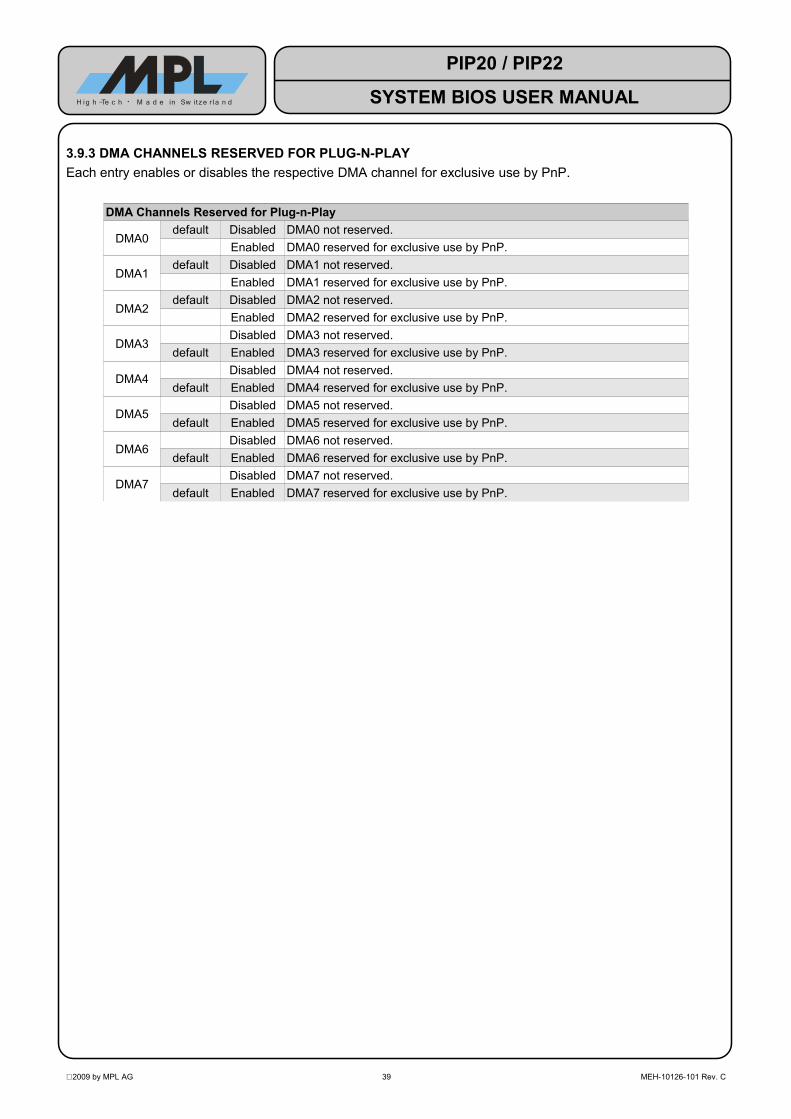
3.9.3 DMA CHANNELS RESERVED FOR PLUG-N-PLAYEach entry enables or disables the respective DMA channel for exclusive use by PnP.
DMA Channels Reserved for Plug-n-Play
DMA0default Disabled DMA0 not reserved.
Enabled DMA0 reserved for exclusive use by PnP.
DMA1default Disabled DMA1 not reserved.
Enabled DMA1 reserved for exclusive use by PnP.
DMA2default Disabled DMA2 not reserved.
Enabled DMA2 reserved for exclusive use by PnP.
DMA3Disabled DMA3 not reserved.
default Enabled DMA3 reserved for exclusive use by PnP.
DMA4Disabled DMA4 not reserved.
default Enabled DMA4 reserved for exclusive use by PnP.
DMA5Disabled DMA5 not reserved.
default Enabled DMA5 reserved for exclusive use by PnP.
DMA6Disabled DMA6 not reserved.
default Enabled DMA6 reserved for exclusive use by PnP.
DMA7Disabled DMA7 not reserved.
default Enabled DMA7 reserved for exclusive use by PnP.
2009 by MPL AG 39 MEH-10126-101 Rev. C
PIP20 / PIP22
SYSTEM BIOS USER MANUALH ig h -Te c h • M a d e in Sw itze r l a n d

3.10 SIO SETUP MENUThe SIO Setup Menu configures the devices of the PIP's SCH3114 Super I/O device (Serial ports and Parallel port).
System Configuration Utility Main Exit Boot POST PnP SIO Features Firmbase Misc >+--------------------------------------------------------+---------------------+| BIOS Super I/O Configuration |Enable or Disable || -------------------------------------------------------|Serial Port 1. || | || SCH3114 Devices | || -------------------------------------------------------| || Serial Port 1 [Enabled] | || Address [3F8h] | || IRQ [IRQ 4] | || Serial Port 3 [Enabled] | || Address [3E8h] | || IRQ [IRQ 4] | || Serial Port 2 [Enabled] | || Mode [RS-232] | || Address [2F8h] | || IRQ [IRQ 3] | || Serial Port 4 [Enabled] | || Mode [RS-232] | || Address [2E8h] | || IRQ [IRQ 3] | || Parallel Port [Enabled] | |+--------------------------------------------------------+---------------------+Embedded BIOS(R) w/StrongFrame(R) Technology - (c)2008 Phoenix Technologies Ltd
3.10.1 SERIAL PORT 1 SETTINGS
Serial Port 1 Enables / Disables Serial Port 1
Disabled Serial Port 1 is disabled. The Serial Port 1 options described below become inactive.
default Enabled Serial Port 1 is enabled (RS232 mode)Address Selects Serial Port 1 I/O base address
default 03F8h Use I/O base address 03F8h02F8h Use I/O base address 02F8h03E8h Use I/O base address 03E8h02E8h Use I/O base address 02E8h0220h Use I/O base address 0220h0228h Use I/O base address 0228h0238h Use I/O base address 0238h0338h Use I/O base address 0338h
IRQ Selects Serial Port 1 IRQ3 Use IRQ 3
default 4 Use IRQ 4 (default: shared1 with Serial Port 3)5 Use IRQ 57 Use IRQ 7
11 Use IRQ 11
1 Some operating systems are not capable of sharing interrupts between two serial ports. In such cases, select a unique interrupt for each serial port, e.g. Serial Port 1 = IRQ4, Serial Port 3 = IRQ11.
2009 by MPL AG 40 MEH-10126-101 Rev. C
PIP20 / PIP22
SYSTEM BIOS USER MANUALH ig h -Te c h • M a d e in Sw itze r l a n d

3.10.2 SERIAL PORT 3 SETTINGS
Serial Port 3 Enables / Disables Serial Port 3
Disabled Serial Port 3 is disabled. The Serial Port 3 options described below become inactive.
default Enabled Serial Port 3 is enabled (RS232 mode)Address Selects Serial Port 3 I/O base address
03F8h Use I/O base address 03F8h02F8h Use I/O base address 02F8h
default 03E8h Use I/O base address 03E8h02E8h Use I/O base address 02E8h0220h Use I/O base address 0220h0228h Use I/O base address 0228h0238h Use I/O base address 0238h0338h Use I/O base address 0338h
IRQ Selects Serial Port 3 IRQ3 Use IRQ 3
default 4 Use IRQ 4 (default: shared2 with Serial Port 1)5 Use IRQ 57 Use IRQ 7
11 Use IRQ 11
3.10.3 SERIAL PORT 2 SETTINGSNOTE: In order to use Serial Port 2, the PIP must be equipped with either a SERIF-1 module (for RS-232)
or a SERIF-2 module for RS-485/RS-422).
Serial Port 2 Selects Serial Port 2 mode
Disabled Serial Port 2 is disabled. The Serial Port 2 options described below become inactive.
default RS-232 RS232 mode (requires SERIF-1 module)RS-485 Half Duplex RS485 half–duplex mode (requires SERIF-2 module)RS-485 Full Duplex RS485 / RS422 full-duplex mode (requires SERIF-2 module)
Address Selects Serial Port 2 I/O base address03F8h Use I/O base address 03F8h
default 02F8h Use I/O base address 02F8h03E8h Use I/O base address 03E8h02E8h Use I/O base address 02E8h
IRQ Selects Serial Port 2 IRQdefault 3 Use IRQ 3 (default: shared3 with Serial Port 4)
4 Use IRQ 45 Use IRQ 57 Use IRQ 7
11 Use IRQ 11
2 Some operating systems are not capable of sharing interrupts between two serial ports. In such cases, select a unique interrupt for each serial port, e.g. Serial Port 1 = IRQ4, Serial Port 3 = IRQ11.
3 Some operating systems are not capable of sharing interrupts between two serial ports. In such cases, select a unique interrupt for each serial port, e.g. Serial Port 2 = IRQ3, Serial Port 4 = IRQ5.
2009 by MPL AG 41 MEH-10126-101 Rev. C
PIP20 / PIP22
SYSTEM BIOS USER MANUALH ig h -Te c h • M a d e in Sw itze r l a n d

3.10.4 SERIAL PORT 4 SETTINGSNOTE: In order to use Serial Port 4, the PIP must be equipped with either a SERIF-1 module (for RS-232) or
a SERIF-2 module for RS-485/RS-422).
Serial Port 4 Selects Serial Port 4 mode
Disabled Serial Port 2 is disabled. The Serial Port 2 options described below become inactive.
default RS-232 RS232 mode (requires SERIF-1 module)RS-485 Half Duplex RS485 half–duplex mode (requires SERIF-2 module)RS-485 Full Duplex RS485 / RS422 full-duplex mode (requires SERIF-2 module)
Address Selects Serial Port 2 I/O base address03F8h Use I/O base address 03F8h02F8h Use I/O base address 02F8h03E8h Use I/O base address 03E8h
default 02E8h Use I/O base address 02E8hIRQ Selects Serial Port 2 IRQ
default 3 Use IRQ 3 (default: shared4 with Serial Port 24 Use IRQ 45 Use IRQ 57 Use IRQ 7
11 Use IRQ 11
4 Some operating systems are not capable of sharing interrupts between two serial ports. In such cases, select a unique interrupt for each serial port, e.g. Serial Port 2 = IRQ3, Serial Port 4 = IRQ5.
2009 by MPL AG 42 MEH-10126-101 Rev. C
PIP20 / PIP22
SYSTEM BIOS USER MANUALH ig h -Te c h • M a d e in Sw itze r l a n d

3.10.5 PARALLEL PORT SETTINGS
Parallel Port Selects Parallel Port mode
Disabled Parallel Port is disabled. The Parallel Port options described below become hidden.
default SPP Standard bidirectional modePrinter Printer mode
SPP / EPP 1.7 SPP and EPP 1.7 modeSPP / EPP 1.9 SPP and EPP 1.9 mode
ECP ECP modeECP / EPP 1.7 ECP and EPP 1.7 modeECP / EPP 1.9 ECP and EPP 1.9 mode
Address Selects Parallel Port I/O base addressdefault 0378h Use I/O base address 0378h
0278h Use I/O base address 0278hIRQ Selects Parallel Port IRQ
3 Use IRQ 34 Use IRQ 45 Use IRQ 5
default 7 Use IRQ 711 Use IRQ 11
2009 by MPL AG 43 MEH-10126-101 Rev. C
PIP20 / PIP22
SYSTEM BIOS USER MANUALH ig h -Te c h • M a d e in Sw itze r l a n d

3.11 FEATURES SETUP MENU System Configuration Utility Main Exit Boot POST PnP SIO Features Firmbase Misc >+--------------------------------------------------------+---------------------+| BIOS Feature Configuration |Enable to initialize || -------------------------------------------------------|APICs and use them in|| Interrupt Processing [Use APIC] |an emulated PIC mode.|| MP Tables (non-ACPI OSes) [Enabled] |If you wish to use || ACPI [Enabled] |full-APIC mode, this || POST Memory Manager [Enabled] |must be set AND || System Management BIOS [Enabled] |either ACPI or MP || Splash Screen [Disabled] |must be enabled. DO || |NOT CHANGE AFTER OS || Console Redirection |INSTALL. || -------------------------------------------------------| || Use Console Assignments Below [Never] | || POST Console [COM1] | || Preboot Console [COM1] | || Debugger Console [None] | || | || CPU Configuration | || -------------------------------------------------------| || P7 Geyserville/Speedstep [Enabled] | || Intel VT [Disabled] | |+--------------------------------------------------------+---------------------+Embedded BIOS(R) w/StrongFrame(R) Technology - (c)2008 Phoenix Technologies Ltd
3.11.1 BIOS FEATURE CONFIGURATION
3.11.1.1 INTERRUPT PROCESSINGThis option controls how interrupt processing is handled, either in legacy PIC (Programmable Interrupt Controller) mode or in APIC (Advanced Programmable Interrupt Controller) mode.If enabled, the BIOS makes the necessary provisions for the OS to make use of the APIC. But it is the responsibility of the OS to make full use of the APIC mode.
Interrupt ProcessingUse Legacy PIC Legacy PIC is used.
default Use APIC APIC is used.
3.11.1.2 MP TABLES (NON-ACPI OSES)This option enables MP tables which provide the OS with processor and APIC information, according to the MultiProcessor specification.
NOTE: If this option is enabled, 'Interrupt Processing' must be set to 'Use APIC'.
MP Tables (Non-ACPI OSes)Disabled MP tables disabled.
default Enabled MP tables enabled.
3.11.1.3 ACPIThis option enables support for Advanced Configuration and Power Interface (ACPI).
ACPIDisabled ACPI disabled.
default Enabled ACPI enabled.
2009 by MPL AG 44 MEH-10126-101 Rev. C
PIP20 / PIP22
SYSTEM BIOS USER MANUALH ig h -Te c h • M a d e in Sw itze r l a n d
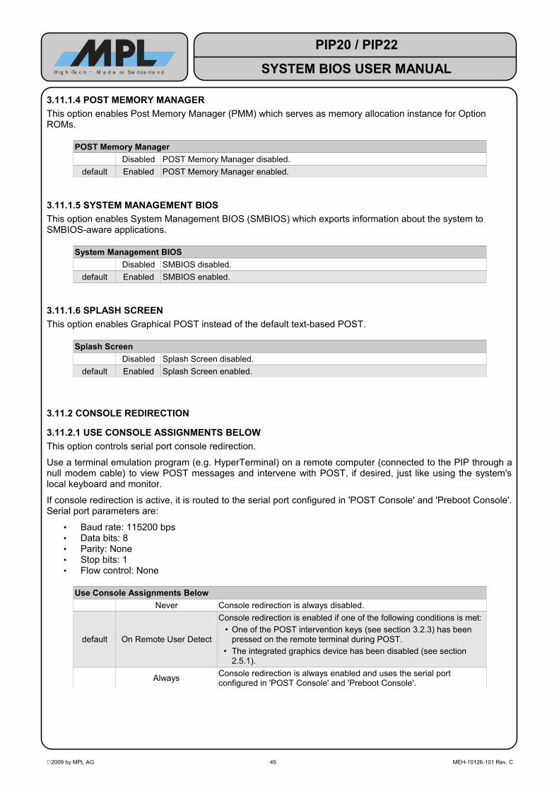
3.11.1.4 POST MEMORY MANAGERThis option enables Post Memory Manager (PMM) which serves as memory allocation instance for Option ROMs.
POST Memory ManagerDisabled POST Memory Manager disabled.
default Enabled POST Memory Manager enabled.
3.11.1.5 SYSTEM MANAGEMENT BIOSThis option enables System Management BIOS (SMBIOS) which exports information about the system to SMBIOS-aware applications.
System Management BIOSDisabled SMBIOS disabled.
default Enabled SMBIOS enabled.
3.11.1.6 SPLASH SCREENThis option enables Graphical POST instead of the default text-based POST.
Splash ScreenDisabled Splash Screen disabled.
default Enabled Splash Screen enabled.
3.11.2 CONSOLE REDIRECTION
3.11.2.1 USE CONSOLE ASSIGNMENTS BELOWThis option controls serial port console redirection.
Use a terminal emulation program (e.g. HyperTerminal) on a remote computer (connected to the PIP through a null modem cable) to view POST messages and intervene with POST, if desired, just like using the system's local keyboard and monitor.
If console redirection is active, it is routed to the serial port configured in 'POST Console' and 'Preboot Console'. Serial port parameters are:
• Baud rate: 115200 bps• Data bits: 8• Parity: None• Stop bits: 1• Flow control: None
Use Console Assignments BelowNever Console redirection is always disabled.
default On Remote User Detect
Console redirection is enabled if one of the following conditions is met:• One of the POST intervention keys (see section 3.2.3) has been
pressed on the remote terminal during POST.• The integrated graphics device has been disabled (see section
2.5.1).
Always Console redirection is always enabled and uses the serial port configured in 'POST Console' and 'Preboot Console'.
2009 by MPL AG 45 MEH-10126-101 Rev. C
PIP20 / PIP22
SYSTEM BIOS USER MANUALH ig h -Te c h • M a d e in Sw itze r l a n d
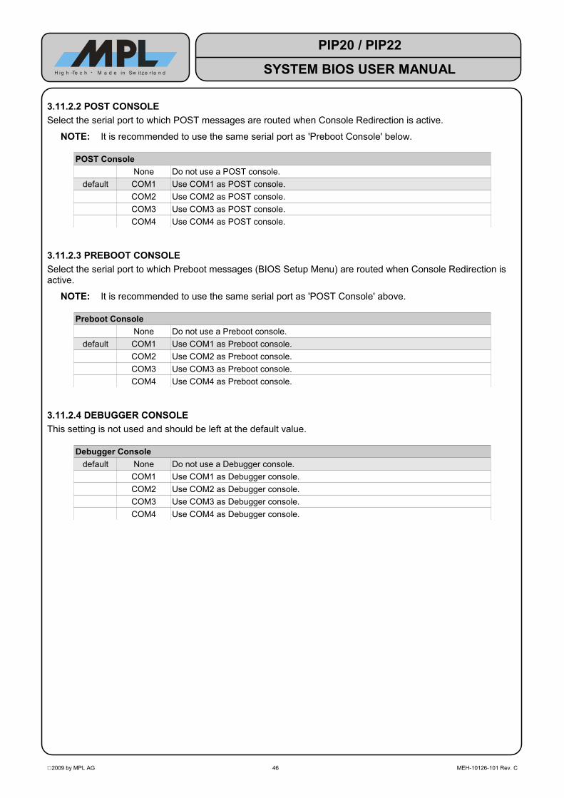
3.11.2.2 POST CONSOLESelect the serial port to which POST messages are routed when Console Redirection is active.
NOTE: It is recommended to use the same serial port as 'Preboot Console' below.
POST ConsoleNone Do not use a POST console.
default COM1 Use COM1 as POST console.COM2 Use COM2 as POST console.COM3 Use COM3 as POST console.COM4 Use COM4 as POST console.
3.11.2.3 PREBOOT CONSOLESelect the serial port to which Preboot messages (BIOS Setup Menu) are routed when Console Redirection is active.
NOTE: It is recommended to use the same serial port as 'POST Console' above.
Preboot ConsoleNone Do not use a Preboot console.
default COM1 Use COM1 as Preboot console.COM2 Use COM2 as Preboot console.COM3 Use COM3 as Preboot console.COM4 Use COM4 as Preboot console.
3.11.2.4 DEBUGGER CONSOLEThis setting is not used and should be left at the default value.
Debugger Consoledefault None Do not use a Debugger console.
COM1 Use COM1 as Debugger console.COM2 Use COM2 as Debugger console.COM3 Use COM3 as Debugger console.COM4 Use COM4 as Debugger console.
2009 by MPL AG 46 MEH-10126-101 Rev. C
PIP20 / PIP22
SYSTEM BIOS USER MANUALH ig h -Te c h • M a d e in Sw itze r l a n d
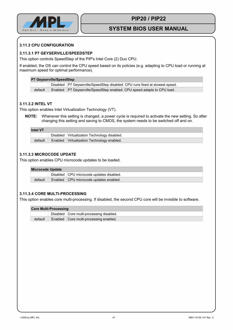
3.11.3 CPU CONFIGURATION
3.11.3.1 P7 GEYSERVILLE/SPEEDSTEPThis option controls SpeedStep of the PIP's Intel Core (2) Duo CPU.
If enabled, the OS can control the CPU speed based on its policies (e.g. adapting to CPU load or running at maximum speed for optimal performance).
P7 Geyserville/SpeedStepDisabled P7 Geyserville/SpeedStep disabled. CPU runs fixed at slowest speed.
default Enabled P7 Geyserville/SpeedStep enabled. CPU speed adapts to CPU load.
3.11.3.2 INTEL VTThis option enables Intel Virtualization Technology (VT).
NOTE: Whenever this setting is changed, a power cycle is required to activate the new setting. So after changing this setting and saving to CMOS, the system needs to be switched off and on.
Intel VTDisabled Virtualization Technology disabled.
default Enabled Virtualization Technology enabled.
3.11.3.3 MICROCODE UPDATEThis option enables CPU microcode updates to be loaded.
Microcode UpdateDisabled CPU microcode updates disabled.
default Enabled CPU microcode updates enabled.
3.11.3.4 CORE MULTI-PROCESSINGThis option enables core multi-processing. If disabled, the second CPU core will be invisible to software.
Core Multi-ProcessingDisabled Core multi-processing disabled.
default Enabled Core multi-processing enabled.
2009 by MPL AG 47 MEH-10126-101 Rev. C
PIP20 / PIP22
SYSTEM BIOS USER MANUALH ig h -Te c h • M a d e in Sw itze r l a n d

3.12 FIRMBASE SETUP MENUThe Firmbase Setup Menu configures Firmbase Technology and its components. Firmbase technology is based on System Management Mode (SMM) and all its components run in SMM.
System Configuration Utility Main Exit Boot POST PnP SIO Features Firmbase Misc >+--------------------------------------------------------+---------------------+| Features Enabled by Firmbase[R] Technology |Enable to support USB|| -------------------------------------------------------|keyboard and mouse. || Legacy USB [Enabled] | || USB Boot [Enabled] | || EHCI/USB 2.0 [Enabled] | || | || Basic Firmbase[R] Technology Configuration | || -------------------------------------------------------| || Firmbase Technology [Enabled] | || Firmbase Debug Log [None] | || Firmbase System Console [None] | || Firmbase Shell on Serial Port [None] | || | || | || | || | || | || | || | || | |+--------------------------------------------------------+---------------------+Embedded BIOS(R) w/StrongFrame(R) Technology - (c)2008 Phoenix Technologies Ltd
3.12.1 FEATURES ENABLED BY FIRMBASE[R] TECHNOLOGYAll these features require that Firmbase Technology is activated. If it is disabled, the remaining options in the Firmbase Setup Menu are disabled.
3.12.1.1 LEGACY USBThis option enables support for USB keyboards and mice in legacy environments, such as DOS and the BIOS Setup.
Legacy USBDisabled USB Legacy device support disabled.
default Enabled USB Legacy device support enabled.
3.12.1.2 USB BOOTThis option enables boot support for USB mass storage devices.If disabled, USB devices cannot be selected as boot devices in Boot Setup Menu.
NOTE: If you experience problems with a certain USB device, please disable EHCI/USB 2.0 (see section 3.12.1.3). If this does not help, try a different USB device. There is a vast variety of USB devicesavailable on the market, and some of them may prove incompatible with the USB host controller ofthe PIP20/PIP22.
USB BootDisabled USB Boot support disabled.
default Enabled USB Boot support enabled.
2009 by MPL AG 48 MEH-10126-101 Rev. C
PIP20 / PIP22
SYSTEM BIOS USER MANUALH ig h -Te c h • M a d e in Sw itze r l a n d

3.12.1.3 EHCI/USB 2.0This option enables support for EHCI / USB 2.0.
This option can be used in case a certain USB 2.0 device does not work properly. By disabling this option, the device will be limited to USB 1.1 (aka USB 2.0 Full-Speed) mode instead of USB 2.0 Hi-Speed mode.
EHCI/USB 2.0Disabled EHCI/USB 2.0 support disabled.
default Enabled EHCI/USB 2.0 support enabled.
3.12.2 BASIC FIRMBASE[R] TECHNOLOGY CONFIGURATION
3.12.2.1 FIRMBASE TECHNOLOGYThis option enables Firmbase Technology which introduces features such as Legacy USB and USB Boot support.
NOTE: Enabling Firmbase Technology implicitly enables System Management Mode (SMM) because all the features are based on SMM and cannot run without it.Due to its nature, SMM may cause problems if the application requires hard real time capabilities. The setup options 'LEGACY USB' (see section 3.12.1.1), 'USB BOOT' (see section 3.12.1.2) and 'EHCI/USB 2.0' (see section 3.12.1.3) are provided to individually disable SMM features in case of problems.
Firmbase TechnologyDisabled Firmbase Technology support disabled.
default Enabled Firmbase Technology support enabled.
3.12.2.2 FIRMBASE DEBUG LOGThis option is intended for debug purposes only and should be left at the default setting 'None'.
3.12.2.3 FIRMBASE SYSTEM CONSOLEThis option is intended for debug purposes only and should be left at the default setting 'None'.
3.12.2.4 FIRMBASE SHELL ON SERIAL PORTThis option is intended for debug purposes only and should be left at the default setting 'None'.
2009 by MPL AG 49 MEH-10126-101 Rev. C
PIP20 / PIP22
SYSTEM BIOS USER MANUALH ig h -Te c h • M a d e in Sw itze r l a n d

3.13 MISC SETUP MENU System Configuration Utility Main Exit Boot POST PnP SIO Features Firmbase Misc >+--------------------------------------------------------+---------------------+| Cache Control |Enable to allow || -------------------------------------------------------|caching to operate. || System Cache [Enabled] | || | || Keyboard Control | || -------------------------------------------------------| || Keyboard Numlock LED [Enabled] | || Typematic Rate [30/sec] | || Typematic Delay [250ms] | || | || Miscellaneous BIOS Configuration | || -------------------------------------------------------| || Lowercase Hex Displays [Disabled] | || | || | || | || | || | || | || | |+--------------------------------------------------------+---------------------+Embedded BIOS(R) w/StrongFrame(R) Technology - (c)2008 Phoenix Technologies Ltd
3.13.1 CACHE CONTROL
3.13.1.1 SYSTEM CACHEThis option enables the System Cache.
System CacheDisabled System Cache is disabled.
default Enabled System Cache is enabled.
3.13.2 KEYBOARD CONTROL
3.13.2.1 KEYBOARD NUMLOCK LEDThis option enables keyboard Numlock.
Keyboard Numlock LEDDisabled Numlock is disabled.
default Enabled Numlock is enabled.
2009 by MPL AG 50 MEH-10126-101 Rev. C
PIP20 / PIP22
SYSTEM BIOS USER MANUALH ig h -Te c h • M a d e in Sw itze r l a n d

3.13.2.2 TYPEMATIC RATEThis option specifies the rate at which characters are repeated when a key is pressed and held down.
Typematic Ratedefault 30/sec Characters repeat 30 times per second.
20/sec Characters repeat 20 times per second.10/sec Characters repeat 10 times per second.8/sec Characters repeat 8 times per second.6/sec Characters repeat 6 times per second.5/sec Characters repeat 5 times per second.4/sec Characters repeat 4 times per second.3/sec Characters repeat 3 times per second.2/sec Characters repeat 2 times per second.
3.13.2.3 TYPEMATIC DELAYThis option specifies the amount of time the key needs to be pressed and held down until the character repetition feature starts.
Typematic Delaydefault 250ms Characters start to repeat after pressing a key for 250ms.
500ms Characters start to repeat after pressing a key for 500ms.750ms Characters start to repeat after pressing a key for 750ms.
1s Characters start to repeat after pressing a key for 1s.
3.13.3 MISCELLANEOUS BIOS CONFIGURATION
3.13.3.1 LOWERCASE HEX DISPLAYSThis setting is not used and should be left at the default value.
Lowercase HEX Displaysdefault Disabled Do not display hexadecimal numbers in debugger in lower case.
Enabled Display hexadecimal numbers in debugger in lower case.
2009 by MPL AG 51 MEH-10126-101 Rev. C
PIP20 / PIP22
SYSTEM BIOS USER MANUALH ig h -Te c h • M a d e in Sw itze r l a n d

3.14 SPECIAL SETUP MENU System Configuration Utility< Boot POST PnP SIO Features Firmbase Misc Special Video+--------------------------------------------------------+---------------------+| AC97 Audio Configuration |Autodetect AC97 Sound|| -------------------------------------------------------|device (SoundPAN-1 || AC97 Audio Support [Auto] |option). || | || PC/104 Memory Configuration | || -------------------------------------------------------| || PC/104 Mem Base Address [Disabled] | || PC/104 Mem Length [16k] | || | || PS/2 Connector Configuration | || -------------------------------------------------------| || PS/2 Connector Mode [Auto (Y-cable)] | || | || | || | || | || | || | || | || | |+--------------------------------------------------------+---------------------+Embedded BIOS(R) w/StrongFrame(R) Technology - (c)2008 Phoenix Technologies Ltd
3.14.1 AC97 AUDIO CONFIGURATION
3.14.1.1 AC97 AUDIO SUPPORTThis option controls the onboard AC'97 audio device.
NOTE: This option is only useful if the MPL SoundPAN-1 option is installed.
AC97 Audio SupportDisabled AC'97 is disabled.
default Auto AC'97 audio device is enabled automatically if the MPL SoundPAN-1 option isinstalled. If SoundPAN-1 is not present, the AC'97 device is disabled.
3.14.2 PC/104 MEMORY CONFIGURATION
3.14.2.1 PC/104 MEM BASE ADDRESSThis option reserves memory space for legacy PC/104 (ISA-based) cards.The possible range for the PC/104 memory space is 000D0000h – 000DFFFFh (segments D000, D400, D800, DC00). Please refer to section 2.2 for more details about the memory map.
PC/104 Mem Base Addressdefault Disabled PC/104 memory window is disabled
D000 PC/104 memory window starts at segment address D000.D400 PC/104 memory window starts at segment address D400.D800 PC/104 memory window starts at segment address D800.DC00 PC/104 memory window starts at segment address DC00.
2009 by MPL AG 52 MEH-10126-101 Rev. C
PIP20 / PIP22
SYSTEM BIOS USER MANUALH ig h -Te c h • M a d e in Sw itze r l a n d

3.14.2.2 PC/104 MEM LENGTHThis option reserves memory space for legacy PC/104 (ISA-based) cards.
PC/104 Mem Lengthdefault 16k PC/104 memory window size 16k (4000h)
32k PC/104 memory window size 32k (8000h).64k PC/104 memory window size 64k (10000h).
3.14.3 PS/2 CONNECTOR CONFIGURATION
3.14.3.1 PS/2 CONNECTOR MODEThis option controls the PS/2 connector of the PIP.
The PS/2 connector contains both the keyboard and the mouse signal pairs. To support differentconfigurations, these signals can be swapped. The PIP BIOS offers automatic detection of the connecteddevices, but this feature can be disabled if required.
Keyboard and mouse devices can either be plugged directly into the PS/2 port or they can be usedsimultaneously with the help of a so-called Y cable.
Normally, the default setting 'Auto (Y-Cable)' works for any configuration. However, if the automatic detectiondoes not work properly for a certain device or if additional devices such as KVM switches (Keyboard, Video,Mouse) are connected between the PIP and the keyboard/mouse, it may be necessary to turn off automaticdetection and use one of the fixed options.
AC97 Audio Support
default Auto (Y-cable) Automatically detect attached PS/2 device(s) and configure PS/2 portaccordingly.
Keyboard direct
Support keyboard plugged directly into the PS/2 connector.Mouse is also supported if Y-cable is used and the devices are connectedproperly.
No automatic detection of PS/2 device(s).
Mouse direct
Support mouse plugged directly into the PS/2 connector.Keyboard is also supported if Y-cable is used and the devices are connectedproperly.
No automatic detection of PS/2 device(s).
Mouse disabledSupport keyboard plugged directly into the PS/2 connector.Mouse is not supported.
No automatic detection of PS/2 device(s).
2009 by MPL AG 53 MEH-10126-101 Rev. C
PIP20 / PIP22
SYSTEM BIOS USER MANUALH ig h -Te c h • M a d e in Sw itze r l a n d

3.15 VIDEO SETUP MENU System Configuration Utility< POST PnP SIO Features Firmbase Misc Special Video >+--------------------------------------------------------+---------------------+| LVDS Panel Settings |Choose the method of || -------------------------------------------------------|backlight brightness || Panel Backlight [BIOS Control] |control of LCD panels|| Panel Brightness (percent) [100] |connected to the LVDS|| Panel Fitting [Default] |connector. || | || GMCH Settings | || -------------------------------------------------------| || Initialize IGD on S3 Resume [Disabled] | || IGD Function 1 [Enabled] | || Video Frame Buffer Size [8MB] | || | || | || | || | || | || | || | || | || | |+--------------------------------------------------------+---------------------+Embedded BIOS(R) w/StrongFrame(R) Technology - (c)2008 Phoenix Technologies Ltd
3.15.1 LVDS PANEL SETTINGSThese options control panels connected to the PIP via LVDS interface.Please refer to section 2.5.2 for detailed information about the Flat Panel (LVDS) interface of the PIP.
NOTE: These options are only active if a LVDS panel is connected and properly configured via DIP switches. If the monitor is connected to the DVI-I port of the PIP, these options are inactive and do not affect the display output.
3.15.1.1 PANEL BACKLIGHTThis option defines how the backlight brightness level is controlled. If set to “BIOS Control”, the brightness canbe adjusted with the option 'Panel Brightness (percent)'.
Panel BacklightHW/App Control Brightness is controlled by hardware or application.
default BIOS Control Brightness is controlled by BIOS setup.
3.15.1.2 PANEL BRIGHTNESS (PERCENT)If 'Panel Backlight' is set to 'BIOS Control', the backlight brightness can be adjusted in 5% increments.
Panel Brightness (percent)Minimum Minimal brightness level.
5 5% brightness level.10 10% brightness level.... ...... [5% increments]... ...95 95% brightness level.
default 100 100% brightness level.
2009 by MPL AG 54 MEH-10126-101 Rev. C
PIP20 / PIP22
SYSTEM BIOS USER MANUALH ig h -Te c h • M a d e in Sw itze r l a n d

3.15.1.3 PANEL FITTINGThis option controls the fitting of the panel contents.If the native resolution of a panel does not correspond to the software resolution, the contents is either stretchedto fit the native screen resolution or centered, which results in a black frame around the actual screen content.
Panel Backlightdefault Default Brightness is controlled by hardware or application.
Center All Modes Both Graphics and Text modes are centered.Stretch All Modes Always fit the screen size.
Stretch Text Modes Text modes are stretched to fit the screen.Stretch Graphics Modes Graphics Modes are stretched to fit the screen.
3.15.2 GMCH SETTINGS
3.15.2.1 INITIALIZE IGD ON S3 RESUMEThis option defines whether the Integrated Graphics Device (IGD) is re-initialized upon a S3 resume.
Initialize IGD on S3 Resumedefault Disabled Do not re-initialize IGD on S3 resume.
Enabled Re-initialize IGD on S3 resume.
3.15.2.2 IGD FUNCTION 1This option enables or disables Integrated Graphics Device (IGD) function 1 (PCI device Bus0 Dev2 Fun1).Depending on the operating system and graphics drivers, it can be useful to disable IGD function 1.
IGD Function 1Disabled Integrated Graphics Device Function 1 is disabled.
default Enabled Integrated Graphics Device Function 1 is enabled.
3.15.2.3 VIDEO FRAME BUFFER SIZEThis option defines the initial size of the video frame buffer.
NOTE: This setting only applies to environments without Intel Graphics Driver, such as DOS.Intel Graphics Drivers override this setting in order to provide a larger frame buffer to the operating system.
Video Frame Buffer Size1MB Initial frame buffer size is 1MB.
default 8MB Initial frame buffer size is 8MB.
2009 by MPL AG 55 MEH-10126-101 Rev. C
PIP20 / PIP22
SYSTEM BIOS USER MANUALH ig h -Te c h • M a d e in Sw itze r l a n d

3.16 ADVANCED INFO SETUP MENUThe Advanced Info Setup Menu displays advanced information about the CPU and Ethernet controllers.
System Configuration Utility< SIO Features Firmbase Misc Special Video AdvancedInfo +--------------------------------------------------------+---------------------+| CPU Information | || -------------------------------------------------------| || CPU Model and Stepping: 06F6h | || CPU Microcode Version: C8h | || On-Die Thermal Sensor, °C: 55 | || | || Ethernet Information | || -------------------------------------------------------| || LAN 1 MAC Address: 00:60:C2:14:00:2E | || LAN 2 MAC Address: 00:60:C2:14:00:2F | || | || | || | || | || | || | || | || | || | || | |+--------------------------------------------------------+---------------------+Embedded BIOS(R) w/StrongFrame(R) Technology - (c)2008 Phoenix Technologies Ltd
3.16.1 CPU INFORMATION
3.16.1.1 CPU MODEL AND STEPPINGThis is the CPU information, as returned by the CPUID instruction: family (6), model (F) and stepping (6).
NOTE: This information varies depending on the installed CPU type.
3.16.1.2 CPU MICROCODE VERSIONThis shows the microcode version that is loaded in the system's CPU.
NOTE: This information varies depending on the installed CPU type and the BIOS version.
3.16.1.3 ON-DIE THERMAL SENSOR, °CThis is the current CPU temperature, in degrees Celsius.
3.16.2 ETHERNET INFORMATION
3.16.2.1 LAN 1 MAC ADDRESSThis is the Media Control Access (MAC) address of onboard LAN 1.
NOTE: If LAN 1 is disabled, the message 'Controller Disabled' will be displayed instead of the MAC address.
3.16.2.2 LAN 2 MAC ADDRESSThis is the Media Access Control (MAC) address of onboard LAN 2.
NOTE: If LAN 2 is disabled, the message 'Controller Disabled' will be displayed instead of the MAC address.
2009 by MPL AG 56 MEH-10126-101 Rev. C
PIP20 / PIP22
SYSTEM BIOS USER MANUALH ig h -Te c h • M a d e in Sw itze r l a n d

4 NETWORK BOOT (PXE)The PIP BIOS supports booting from the two onboard Ethernet controllers using the PXE protocol.Network Boot can be selected as boot action in the Boot Device Prioritization (BBS) menu (please refer to section 3.7 for more information).
The PXE Network Boot Option ROM shows the following message:
Initializing Intel(R) Boot Agent GE v1.3.35PXE 2.1 Build 087 (WfM 2.0)Press Ctrl+S to enter the Setup Menu...
NOTE: If the boot message above does not appear, the PXE Option ROM is not executed which means that the system will not be able to boot from network.
If both Ethernet controllers are configured as boot actions, the PXE Option ROM will be executed twice (once for each Ethernet controller), so the boot message also appears twice.
4.1 PXE SETUP MENUThe PXE setup menu is entered by pressing CTRL+S when indicated by the PXE initialization message (see above).
NOTE: Each Ethernet controller contains its own configuration menu. Changes made for one Ethernetcontroller do not affect the other Ethernet controller!
Intel(R) Boot Agent GE v1.3.35
Setup Menu╔══════════════════════════════════════════════════════════════════════════════╗║ ║║ Network Boot Protocol PXE (Preboot eXecution Environment) ║║ Boot Order Use BIOS Setup Boot Order ║║ Show Setup Prompt Enabled ║║ Setup Menu Wait Time 2 seconds ║║ ║╚══════════════════════════════════════════════════════════════════════════════╝
Diagnostic Support InformationPWA Number FFFFFF-0FF MAC Address 0060C214002E
Memory FBFE0000 I/O FCC0 IRQ 09 UMB D0000PCI ID 8086/109A/8086/0000/00 Slot 0100
Flags 0128:4000:0000:0001:1102:LSelect remote boot protocol.
════════════════════════════════════════════════════════════════════════════════ <Esc> <Space> <Enter> <F4> Cancel Changes Change Value Next Option Save Configuration
The PXE setup menu contains configurable settings as well as information about the Ethernet controller (such as MAC address, PCI resource consumption etc.).
2009 by MPL AG 57 MEH-10126-101 Rev. C
PIP20 / PIP22
SYSTEM BIOS USER MANUALH ig h -Te c h • M a d e in Sw itze r l a n d

4.1.1 CONFIGURATION OPTIONS
Network Boot Protocoldefault PXE (Preboot eXecution Environment) Use PXE as boot protocol
Boot Order
default Use BIOS Setup Boot Order Use the BIOS setup to define the boot order. Please refer to section 3.7 for more information.
Show Setup PromptDisabled Do not show 'Press Ctrl+S to enter the Setup Menu...'
default Enabled Show 'Press Ctrl+S to enter the Setup Menu...'Setup Menu Wait Time
0 Wait 0 sec for Ctrl+Sdefault 2 Wait 2 sec for Ctrl+S
3 Wait 3 sec for Ctrl+S5 Wait 5 sec for Ctrl+S
4.1.2 KEY ASSIGNMENTSThe following keys are used in the PXE Setup Menu to navigate and modify settings:
Key Action[ESC] Leave PXE Setup Menu and lose any changes.
[SPACE] Change value of currently selected option.[ENTER] Jump to next option.
[F4] Save changes and leave PXE Setup menu.
4.2 BOOTING FROM NETWORKSetting up a server that provides bootable images for network clients is a complex task which is beyond the scope of this manual. The PIP merely makes available the feature of booting from a correctly configured boot server.Please visit the Intel website at http://support.intel.com/support/network/adapter/pro100/bootagent/index.htm or search the internet for further information about PXE network booting.
2009 by MPL AG 58 MEH-10126-101 Rev. C
PIP20 / PIP22
SYSTEM BIOS USER MANUALH ig h -Te c h • M a d e in Sw itze r l a n d

This page is left blank intentionally.
2009 by MPL AG 59 MEH-10126-101 Rev. C
PIP20 / PIP22
SYSTEM BIOS USER MANUALH ig h -Te c h • M a d e in Sw itze r l a n d

5 COPYRIGHTCopyright © 2009 by MPL AG Elektronikunternehmen. All rights are reserved. Reproduction of this document in part or whole, by any means is prohibited, without written permission from MPL AG Elektronikunternehmen.
6 DISCLAIMERMPL AG has fully tested the PIP and reviewed the documentation. However, MPL AG makes no warranty or representation, either expressed, or implied, with respect to this product, its quality, performance, merchantability, or fitness for a particular purpose.In no event will MPL AG be liable for direct, indirect, special, incidental, or consequential damages resulting from any defect in the product or its documentation, even if advised of the possibility of such damages. In particular MPL AG shall have no liability for any parts connected to this product.MPL AG reserves the right to make changes to any product herein to improve reliability, function or design.
7 TRADEMARKSBrand or product names are trademarks and registered trademarks of their respective holders.
8 SUPPORTIn case of general information questions please feel free to contact us at our homepage (www.mpl.ch) or per email ([email protected]).In case of sales information questions please send an email to [email protected] you have a technical problem with a PIP, first please read the User Manual, the Technical Reference Manual and also this manual carefully. If you can’t solve the problem on your own you can contact us for technical support per email at [email protected].
Our local Distributor:
2009 by MPL AG 60 MEH-10126-101 Rev. C
PIP20 / PIP22
SYSTEM BIOS USER MANUALH ig h -Te c h • M a d e in Sw itze r l a n d