pioneer gmd8400m uk manual
DESCRIPTION
Pioneer GMD8400M UK ManualTRANSCRIPT

EN
GLIS
HES
PA
ÑO
LD
EU
TS
CH
FR
AN
ÇA
ISIT
ALIA
NO
NED
ERLA
ND
Sê
ìë
ëä
àâ
CLASS D MONO AMPLIFIER
AMPLIFICATEUR MONO DE CLASSE D
éÑçéäÄçÄãúçõâ ìëàãàíÖãú äãÄëëÄ D
Owner’s Manual
GM-D8400MMode d’emploi

1
Before Using This Product ...................... 1Visit our website ................................................ 1In case of trouble .............................................. 2About This Product .......................................... 2CAUTION ........................................................ 2WARNING ........................................................ 2
Setting the Unit .......................................... 3Gain Control ...................................................... 3LPF (Low-Pass-Filter) Cut Off Frequency
Control ........................................................ 4Power Indicator (Blue) ...................................... 4BFC (Beat Frequency Control) Switch ............ 4Input Switch ...................................................... 4Bass Boost Control ............................................ 4Setting the Gain properly .................................. 5
Connecting the Unit .................................. 6Connection Diagram ........................................ 7Solderless Terminal Connections ...................... 8Connecting the Power Terminal ........................ 8Connecting the Speaker Output Terminals ...... 9Using the Speaker Input .................................... 9Connecting the Speaker Wires .......................... 9
Installation ................................................ 10Attaching the Bass boost remote control ........ 11Example of installation on the floor mat
or on the chassis ...................................... 11
Specifications .......................................... 12
Thank you for purchasing this PIONEERproduct. Before attempting operation, besure to read this manual.
Private households in the member states ofthe EU, in Switzerland and Norway mayreturn their used electronic products freeof charge to designated collection facilitiesor to a retailer (if you purchase a similarnew one).For countries not mentioned above, pleasecontact your local authorities for the correct method of disposal.By doing so you will ensure that your disposed product undergoes the necessarytreatment, recovery and recycling and thusprevent potential negative effects on theenvironment and human health.
Visit our websiteVisit us at the following site:http://www.pioneer.co.uk• Register your product. We will keep the
details of your purchase on file to helpyou refer to this information in the eventof an insurance claim such as loss ortheft.
• We offer the latest information aboutPioneer Corporation on our website.
If you want to dispose thisproduct, do not mix it withgeneral household waste. Thereis a separate collection systemfor used electronic products inaccordance with legislation thatrequires proper treatment,recovery and recycling.
Contents Before Using This Product

EN
GLIS
HES
PA
ÑO
LD
EU
TS
CH
FR
AN
ÇA
ISIT
ALIA
NO
NED
ERLA
ND
Sê
ìë
ëä
àâ
2
In case of troubleWhen the unit does not operate properly,contact your dealer or the nearest autho-rized PIONEER Service Station.
About This ProductThis product is a class D amplifier for thesubwoofer. If both L (left) and R (right)channels are connected to the RCA inputof this product, output is mixed becausethis product is a mono amplifier.
CAUTION• Never replace the fuse with one of greater value
or rating than the original fuse. Use of an improper fuse could result in overheating andsmoke and could cause damage to the productand injury including burns.
• Use the supplied hexagonal wrench to tightenscrews when fastening wires to the terminal. Theuse of a long, commercially available hexagonalwrench can cause excessive torque to be appliedpossibly resulting in damage to terminals andwires.
WARNING• We recommend that you use the special red bat-
tery and ground wire [RD-228], which is soldseparately. Connect the battery wire directly tothe car battery positive terminal (+) and theground wire to the car body.
• Do not touch the amplifier with wet hands.Otherwise you may get an electric shock. Also,do not touch the amplifier when it is wet.
• For traffic safety and to maintain safe driving conditions, keep the volume low enough so thatyou can still hear normal traffic sound.
• Check the connections of the power supply andsubwoofer if the fuse of the separately sold bat-tery wire or the amplifier fuse blows. Detect thecause and solve the problem, then replace thefuse with another one of the same size and rating.
• To prevent malfunction of the amplifier and sub-woofer, the protective circuit will cut the powersupply to the amplifier (sound will stop) when anabnormal condition occurs. In such a case, switchthe power to the system OFF and check the connection of the power supply and subwoofer.Detect the cause and solve the problem.
• Contact the dealer if you cannot detect the cause.• To prevent an electric shock or short-circuit
during connection and installation, be sure to disconnect the negative (–) terminal of the batterybeforehand.
• Confirm that no parts are behind the panel whendrilling a hole for installation of the amplifier. Besure to protect all cables and important equipmentsuch as fuel lines, brake lines and the electricalwiring from damage.
• DO NOT allow amplifier to come into contactwith liquids due to, for example, the locationwhere the amplifier is installed. Electrical shockcould result. Also, amplifier and speaker damage,smoke, and overheating could result from contactwith liquids. In addition, the amplifier surfaceand the surface of any attached speakers couldbecome hot to the touch and minor burns couldresult.
3
Setting the Unit
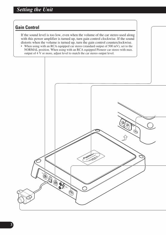
Gain ControlIf the sound level is too low, even when the volume of the car stereo used alongwith this power amplifier is turned up, turn gain control clockwise. If the sounddistorts when the volume is turned up, turn the gain control counterclockwise.• When using with an RCA equipped car stereo (standard output of 500 mV), set to the
NORMAL position. When using with an RCA equipped Pioneer car stereo with max.output of 4 V or more, adjust level to match the car stereo output level.

EN
GLIS
HES
PA
ÑO
LD
EU
TS
CH
FR
AN
ÇA
ISIT
ALIA
NO
NED
ERLA
ND
Sê
ìë
ëä
àâ
4
Power Indicator (Blue)The power indicator lights when the power is switched on.
BFC (Beat Frequency Control) SwitchIf you hear a beat while listening to an MW/LW broadcast with your car stereo, change theBFC switch using a small standard tip screwdriver.
LPF (Low-Pass-Filter) Cut Off Frequency ControlYou can select a cut off frequency from 40 Hz to 240 Hz.
Bass Boost ControlYou can adjust a bass boost level from 0 dB to 12 dB.For instruction of connecting the bass boost remote control to the amplifier, see the“Connection Diagram” section.
Input SwitchIt is possible to input from a car stereo external output or a car stereo speaker output. Switchthe input switch before turning on the power. Since switching the input switch while thepower is on can cause a loud noise to be emitted from the speakers, the power is turned offby a protection function. When using an external output, slide the switch to the right (RCA).For connection instructions, see the “Connection Diagram” section. When using a speakeroutput, slide the switch to the left (SP). In this case, it is necessary to use the supplied speak-er input wire with RCA pin cord. For details, see the “Using the Speaker Input” section.
5
Setting the Unit
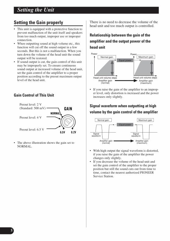
Setting the Gain properly• This unit is equipped with a protective function to
prevent malfunction of the unit itself and speakersfrom too much output, improper use or improperconnection.
• When outputting sound at high volume etc., thisfunction will cut off the sound output in a fewseconds. But this is not a malfunction. When youturn down the volume of the head unit the soundoutput will be restored.
• If sound output is cut, the gain control of this unitmay be improperly set. To ensure continuoussound output at increased volume of the head unit,set the gain control of the amplifier to a properposition according to the preout maximum outputlevel of the head unit.
Gain Control of This Unit
• The above illustration shows the gain set toNORMAL.
There is no need to decrease the volume of thehead unit and too much output is controlled.
Relationship between the gain of theamplifier and the output power of thehead unit
• If you raise the gain of the amplifier to an improp-er level, only distortion is increased and the powerincreases only slightly.
Signal waveform when outputting at highvolume by the gain control of the amplifier
• With high output the signal waveform is distorted,if you raise the gain of the amplifier the powerchanges only slightly.
• If you decrease the volume of the head unit andset the gain control of the amplifier to the properposition but still the sound cuts out from time totime, contact the nearest authorized PIONEERService Station.
Equal power
Amplifier gain(normal)
Amplifier gain(maximum)
Signalwaveform
Signalwaveform
Normal gain Maximum gain
Amplifier gain(normal)
Amplifier gain(maximum)
Head unit volume steps
PowerNormal gain
Power
Head unit volume steps
Maximum gain
Equal power
Preout level: 2 V (Standard: 500 mV)
Preout level: 4 V
Preout level: 6.5 V

Connecting the Unit
6
EN
GLIS
HES
PA
ÑO
LD
EU
TS
CH
FR
AN
ÇA
ISIT
ALIA
NO
NED
ERLA
ND
Sê
ìë
ëä
àâ
CAUTION• Disconnect the negative (–) terminal of the bat-
tery to avoid the risk of short-circuit and damageto the unit.
• Secure the wiring with cable clamps or adhesivetape. To protect the wiring, wrap adhesive tapearound it where they lie against metal parts.
• Do not route wires where they will get hot, forexample where the heater will blow over them. Ifthe insulation heats up, it may become damaged,resulting in a short-circuit through the vehiclebody.
• Make sure that wires will not interfere with mov-ing parts of the vehicle, such as the gearshift,handbrake or seat sliding mechanism.
• Do not shorten any wires. Otherwise the protec-tion circuit may fail to work when it should.
• Never feed power to other equipment by cuttingthe insulation of the power supply wire to tapfrom the wire. The current capacity of the wirewill be exceeded, causing overheating.
• Never replace the fuse with one of greater valueor rating than the original fuse. Use of an improp-er fuse could result in overheating and smoke andcould cause damage to the product and injuryincluding burns.
CAUTION:To prevent damage and/or injury• Do not ground the speaker wire directly or con-
nect a negative (–) lead wire for several speakers.• This unit is for vehicles with a 12-volt battery and
negative grounding. Before installing it in a recre-ational vehicle, truck or bus, check the batteryvoltage.
• If the car stereo is kept on for a long time whilethe engine is at rest or idling, the battery may godead. Turn the car stereo off when the engine is atrest or idling.
• If the system remote control wire of the amplifieris connected to the power terminal through theignition switch (12 V DC), the amplifier willalways be on when the ignition is on— regardlessof whether the car stereo is on or off. Because ofthis, the battery could go dead if the engine is atrest or idling.
• DO NOT connect a subwoofer with a lowerimpedance than specified in the “Connecting theSpeaker Wires” section. Amplifier damage,smoke, and overheating could result from a non-specified connection. The amplifier surface couldalso become hot to the touch and minor burnscould result.
• Connect either of two subwoofers to the amplifi-er; 1: a subwoofer with a 350 W or larger nomi-nal input and an impedance 4 Ω, or 2: a sub-woofer with a 600 W or larger nominal input andan impedance 2 Ω. If the nominal input andimpedance are out of the above ranges, the sub-woofer may catch fire, emit smoke or becomedamaged.
• Install and route the separately sold battery wireas far away as possible from the speaker wires.Install and route the separately sold battery wire,ground wire, speaker wires and the amplifier asfar away as possible from the antenna, antennacable and tuner.

7
Connecting the Unit
Connection Diagram• This diagram shows connections using external output (subwoofer output). Slide the input switch to the
right (RCA).
Fuse (40 A) × 2
Grommet Special red battery wire [RD-228] (sold separately)After making all other connections at the amplifier,connect the battery wire terminal of the amplifier tothe positive (+) terminal of the battery.
Ground wire (black) [RD-228] (sold separately)Connect to metal body or chassis.
Fuse (30 A) × 2
Car stereo withRCA output jacks
External Output(Subwoofer output)
Connecting wire with RCApin plugs (sold separately).
RCA input jack
Speaker terminalSee the “Connecting the Speaker Wires”section for speaker connection instructions.
System remote control wire (sold separately)Connect the male terminal of this wire to the system remote controlterminal of the car stereo (SYSTEM REMOTE CONTROL). Thefemale terminal can be connected to the auto-antenna relay controlterminal. If the car stereo does not have a system remote control ter-minal, connect the male terminal to the power terminal through theignition switch.
Jack for the bass boost remotecontrolConnect this jack and the bassboost remote control with thebass boost remote control wire.
Bass Boost Remote Control
Bass Boost Remote Control Wire
6 m
Reverse side

EN
GLIS
HES
PA
ÑO
LD
EU
TS
CH
FR
AN
ÇA
ISIT
ALIA
NO
NED
ERLA
ND
Sê
ìë
ëä
àâ
8
Solderless Terminal Connections• Do not connect a cord having an exposed core
wire to the power terminals of this amplifier(Power terminal, GND terminal, System remotecontrol terminal). Disconnection or breakage ofthe core wire can cause a fire or short-circuit.
• Since the wire will become loose over time, itmust be periodically inspected and tightened asnecessary.
• Do not solder or bind the ends of the twistedwires.
• Fasten while making sure to not to clamp the insulating sheath of the wire.
• Use the supplied hexagonal wrench to tighten andloosen the terminal screw of the amplifier.Securely fasten the wire with the terminal screw.However, since excessively tightening the termi-nal screw of the System remote control has therisk of damaging the wire, be careful not to tight-en excessively by observing the status of the wirewhen tightening.
Connecting the Power Terminal• We recommend that you use the special red bat-
tery and ground wire [RD-228], which is soldseparately. Connect the battery wire directly tothe car battery positive terminal (+) and theground wire to the car body.
• Recommended wires size (AWG: American WireGauge) is as follows. The battery wire and theground wire must be same size.
• Use a 10 AWG to 20 AWG wire for the systemremote control wire.
Battery Wire and Ground Wire Size
Wire Length less than less than less than
4.5 m 7.2 m 11.4 m
Wire Size 8 AWG 6 AWG 4 AWG
1. Pass the battery wire from theengine compartment to the interiorof the vehicle.• After making all other connections to the
amplifier, connect the battery wire terminalof the amplifier to the positive (+) terminal ofthe battery.
2. Connect the wires to the terminal.• Fix the wires securely with the terminal
screws.
WARNINGFailure to securely fasten the battery wire to the ter-minal using the terminal screws could cause the ter-minal area to overheat and could result in damageand injury including minor burns.
Enginecompartment
Interior ofthe vehicle
Drill a 13 mmhole into thevehicle body.
Insert the O-ring rubbergrommet into the vehiclebody.
Positive (+)terminal
Fuse (40 A) × 2
GND terminal
Power terminal
Battery wire
System remote control terminal
System remote control wire
Ground wire
Terminal screws

9
Connecting the Unit
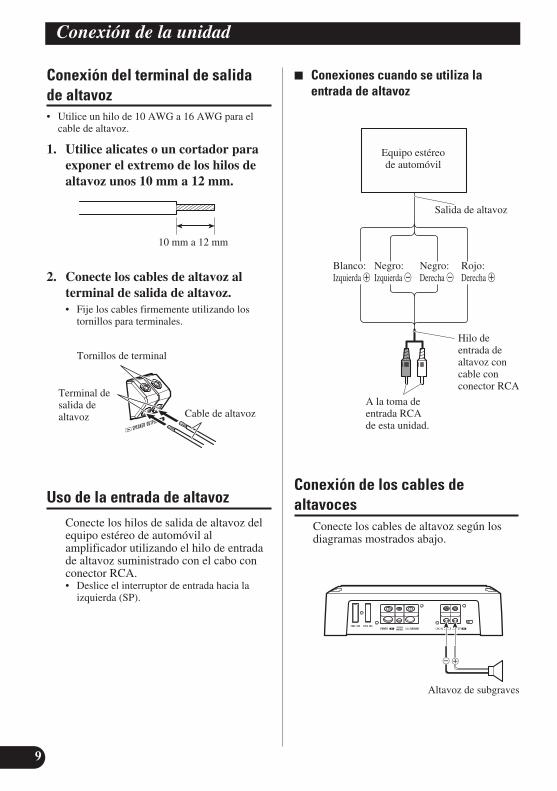
Connecting the Speaker OutputTerminals• Use a 10 AWG to 16 AWG wire for the speaker
wire.
1. Expose the end of the speaker wiresusing nippers or a cutter by about10 mm to 12 mm.
2. Connect the speaker wires to thespeaker output terminals.• Fix the speaker wires securely with the termi-
nal screws.
Using the Speaker InputConnect the car stereo speaker outputwires to the amplifier using the suppliedspeaker input wire with RCA pin cord.• Slide the input switch to the left (SP).
7 Connections when using the speakerinput
Connecting the Speaker WiresConnect the speaker leads according to thefigures shown below.
10 mm to 12 mm
Speaker outputterminal
Terminal screws
Speaker wire
Speaker output
Car Stereo
White: Black: Black: Red:Left + Left ≠ Right ≠ Right +
Speaker input wire with RCApin cord
To RCA inputjack of this unit.
Subwoofer
EN
GLIS
HES
PA
ÑO
LD
EU
TS
CH
FR
AN
ÇA
ISIT
ALIA
NO
NED
ERLA
ND
Sê
ìë
ëä
àâ
10
CAUTION• Do not install in:
—Places where it could injure the driver or pas-sengers if the vehicle stops suddenly.
—Places where it may interfere with the driver,such as on the floor in front of the driver’sseat.
• Make sure that wires are not caught in the slidingmechanism of the seats, resulting in a short-cir-cuit.
• Confirm that no parts are behind the panel whendrilling a hole for installation of the amplifier.Protect all cables and important equipment suchas fuel lines, brake lines and electrical wiringfrom damage.
• Install tapping screws in such a way that thescrew tip does not touch any wire. This is impor-tant to prevent wires from being cut by vibrationof the car, which can result in fire.
• DO NOT allow amplifier to come into contactwith liquids due to, for example, the locationwhere the amplifier is installed. Electrical shockcould result. Also, amplifier and speaker damage,smoke, and overheating could result from contactwith liquids. In addition, the amplifier surfaceand the surface of any attached speakers couldbecome hot to the touch and minor burns couldresult.
• To ensure proper installation, use the suppliedparts in the manner specified. If any parts otherthan the supplied ones are used, they may damageinternal parts of the amplifier, or they maybecome loose causing the amplifier to shut down.
• Never replace the fuse with one of greater valueor rating than the original fuse. Use of an improp-er fuse could result in overheating and smoke andcould cause damage to the product and injuryincluding burns.
CAUTION:To prevent malfunction and/or injury• To ensure proper heat dissipation of the amplifier,
be sure of the following during installation.—Allow adequate space above the amplifier for
proper ventilation.—Do not cover the amplifier with a floor mat
or carpet.• DO NOT allow amplifier to come into contact
with liquids due to, for example, the locationwhere the amplifier is installed. Electrical shockcould result. Also, amplifier and speaker damage,smoke, and overheating could result from contactwith liquids. In addition, the amplifier surfaceand the surface of any attached speakers couldbecome hot to the touch and minor burns couldresult.
• Do not install the amplifier on unstable placessuch as the spare tire board.
• The best location for installation differs with thecar model and installation location. Secure theamplifier at a sufficiently rigid location.
• Make temporary connections first and check thatthe amplifier and the system operate properly.
• After installing the amplifier, confirm that thespare tire, jack and tools can be easily removed.
Installation

11
Installation
Attaching the Bass boost remotecontrolAttach with tapping screws (3 mm × 10 mm) at aneasily accessible location such as under the dash-board.
Example of installation on the floormat or on the chassis
1. Place the amplifier where it is to beinstalled. Insert the supplied tap-ping screws (4 mm × 18 mm) intothe screw holes. Push on the screwswith a screwdriver so they makemarks where the installation holesare to be located.
2. Drill 2.5 mm diameter holes at thepoint marked, and install the ampli-fier, either on the carpet or directlyto the chassis.
Tapping screw (3 mm × 10 mm)
Drill a 2.5 mm diameter hole
Tapping screw (4 mm × 30 mm)
Floor mator chassis

EN
GLIS
HES
PA
ÑO
LD
EU
TS
CH
FR
AN
ÇA
ISIT
ALIA
NO
NED
ERLA
ND
Sê
ìë
ëä
àâ
12
Power source ........................................................................................................ 14.4 V DC (10.8 V to 15.1 V allowable)Grounding system .......................................................................................................................................... Negative typeCurrent consumption .................................................................................................... 27.0 A (at continuous power, 4 Ω)Average current drawn* .......................................................................................................... 7.5 A (4 Ω for one channel)
15.0 A (2 Ω for one channel)Fuse ........................................................................................................................................................................ 30 A × 2Dimensions ........................................................................................................ 290 mm (W) × 56 mm (H) × 200 mm (D)
(Terminals not included)Weight .................................................................................................................... 3.2 kg (Leads for wiring not included)Maximum power output .......................................................................................... 600 W × 1 (4 Ω) / 1 200 W × 1 (2 Ω)Continuous power (14.4 V) .................................................................. 4 Ω, 20 Hz to 240 Hz, 1.0 % THD, 300 W × 1
2 Ω, 50 Hz, 1.0 % THD, 600 W × 1Load impedance ........................................................................................................................ 4 Ω (2 Ω to 8 Ω allowable)Frequency response .......................................................................................................... 10 Hz to 240 Hz (+0 dB, –3 dB)Signal-to-noise ratio ...................................................................................................................... 80 dB (IEC-A network)Distortion .......................................................................................................................................... 0.3 % (10 W, 100 Hz)Low pass filter ............................................................................................................ Cut off frequency: 40 Hz to 240 Hz
Cut off slope: –12 dB/octBass Boost .............................................................................................................................................. Frequency: 50 Hz
Level: 0 dB to 12 dBGain control .................................................................................................................................... RCA: 200 mV to 6.5 V
Speaker: 0.8 V to 26 VMaximum input level / impedance ...................................................................................................... RCA: 6.5 V / 22 kΩ
Speaker: 26 V / 90 kΩ
Note:• Specifications and the design are subject to possible modification without notice
due to improvements.
*Average current drawn• The average current drawn is nearly the maximum current drawn by this unit
when an audio signal is input. Use this value when working out total currentdrawn by multiple power amplifiers.
Specifications

1
Antes de usar este producto .................... 1Visite nuestro sitio Web .................................... 1En caso de desperfectos .................................... 2Sobre este producto .......................................... 2PRECAUCION ................................................ 2ADVERTENCIA .............................................. 2
Ajuste de esta unidad .............................. 3Control de ganancia .......................................... 3Control de frecuencia de corte LPF
(Filtro de paso bajo) .................................. 4Indicador de alimentación (Azul) ...................... 4Interruptor BFC
(Control de la frecuencia de batido) .......... 4Interruptor de entrada ........................................ 4Control de refuerzo de graves .......................... 4Configuración apropiada de la ganancia ............ 5
Conexión de la unidad .............................. 6Diagrama de conexión ...................................... 7Conexiones de terminales sin soldadura .......... 8Conexión del terminal de alimentación ............ 8Conexión del terminal de salida de altavoz ...... 9Uso de la entrada de altavoz .............................. 9Conexión de los cables de altavoces ................ 9
Instalación ................................................ 10Instalación del control remoto de
intensificación de los graves .................... 11Ejemplo de instalación en la alfombra
del piso o en el chasis .............................. 11
Especificaciones .................................... 12
Muchas gracias por la adquisición de esteproducto PIONEER. Antes de tratar deoperarlo, lea atentamente este manual.
Las viviendas privadas en los estadosmiembros de la UE, en Suiza y Noruegapueden devolver gratuitamente susproductos electrónicos usados en lasinstalaciones de recolección previstas o bienen las instalaciones de minoristas (si adquieren un producto similar nuevo).En el caso de los países que no se hanmencionado en el párrafo anterior, póngaseen contacto con sus autoridades locales a finde conocer el método de eliminacióncorrecto.Al actuar siguiendo estas instrucciones, seasegurará de que el producto de desecho sesomete a los procesos de tratamiento,recuperación y reciclaje necesarios, con loque se previenen los efectos negativospotenciales para el entorno y la saludhumana.
Visite nuestro sitio WebVisítenos en el siguiente sitio:http://www.pioneer.es• Registre su producto. Conservaremos
los datos de su compra archivados paraque pueda consultar esta información encaso de que deba efectuar un reclamo ala compañía de seguros por pérdida orobo.
• En nuestro sitio Web ofrecemos la infor-mación más reciente acerca de PioneerCorporation.
Si desea deshacerse de esteproducto, no lo mezcle conlos residuos generales de suhogar. De conformidad con lalegislación vigente, existe unsistema de recogida distintopara los productoselectrónicos que requieren unprocedimiento adecuado detratamiento, recuperación yreciclado.
Contenido Antes de usar este producto

EN
GLIS
HES
PA
ÑO
LD
EU
TS
CH
FR
AN
ÇA
ISIT
ALIA
NO
NED
ERLA
ND
Sê
ìë
ëä
àâ
2
En caso de desperfectosSi esta unidad no funciona correctamente,póngase en contacto con su distribuidor ocon el Centro de Servicio PIONEERautorizado más cercano.
Sobre este productoEste producto es un amplificador de claseD para el altavoz de subgraves. Si amboslos canales L (izquierdo) y R (derecho) seconectan a la entrada RCA de este produc-to, la salida se mezcla ya que este produc-to es un amplificador monofónico.
PRECAUCION• No reemplace nunca el fusible por uno con un
valor de régimen mayor que el fusible original. El uso de un fusible inadecuado podría causar elsobrecalantamiento o humo, así como podríacausar daños al producto y lesiones, incluyendoquemaduras.
• Utilice la llave hexagonal suministrada paraapretar los tornillos al fijar los hilos a losterminales. El uso de una llave hexagonal largadisponible comercialmente puede causar laaplicación de un par de apriete excesivo,resultando en daños a los terminales y hilos.
ADVERTENCIA• Se recomienda utilizar el cable de batería rojo
especial y el cable de tierra [RD-228], vendidosseparadamente. Conecte el cable de bateríadirectamente al terminal positivo de la batería delvehículo (+) y el cable de tierra a la carrocería delvehículo.
• No toque en el amplificador con las manosmojadas. Caso contrario, usted puede llevar unchoque eléctrico. Igualmente, no toque en elamplificador cuando esté mojado.
• Para seguridad del tráfico y para mantenercondiciones de conducción seguras, mantenga elvolumen suficientemente bajo de manera que aunse pueda escuchar el sonido del tráfico normal.
• Verifique las conexiones del suministro deenergía y altavoz de subgraves para ver si elfusible del cable de batería vendidoseparadamente o el fusible del amplificador sequeman. Detecte la causa y solucione elproblema, y reemplace el fusible con un otro delmismo tamaño y régimen.
• Para evitar mal funcionamiento del amplificadory altavoz de subgraves, el circuito de proteccióncortará la alimentación al amplificador (el sonido se detendrá) cuando se produzca unasituación anormal. En tal caso, apague el sistemay verifique la conexión de la alimentación yaltavoz de subgraves. Detecte la causa y resuelva el problema.
• Contacte a su distribuidor si no puede detectar lacausa.
• Para evitar choques eléctricos o cortocircuitorsdurante la conexión e instalación, asegúrese dedesconectar el terminal negativo (–) de la bateríaantes de proceder.
• Confirme que ninguna parte quede detrás delpanel, cuando perfore un orificio para lainstalación del amplificador. Asegúrese deproteger todos los cables y equipos importantes,tales como líneas de combustibles, líneas defrenos y el cableado eléctrico.
• NO permita que el amplificador entre en contactocon líquidos debido a, por ejemplo, la locali-zación donde el amplificador esté instalado. Estopodría causar una sacudida eléctrica. El contactocon líquidos también podría causar daños ysobrecalentamiento al amplificador e altavoces.Además, la superficie del amplificador y lasuperficie de cualquier altavoz instalado tambiénpodrían ponerse muy calientes al tacto, pudiendocausar pequeñas quemaduras.

3
Ajuste de esta unidad
Control de gananciaSi el nivel del sonido está muy bajo, aún cuando se aumenta el volumen delequipo estéreo para automóvil usado con este amplificador de potencia, gire a laderecha el control de ganancia. Si hay distorsión del sonido cuando se aumentael volumen del equipo estéreo de automóvil, gire los controles a la izquierda.• Cuando se usa un estéreo de automóvil equipado con RCA (salida estándar de 500
mV), ajuste a la posición normal. Cuando use con un estéreo de automóvil Pioneerequipado con RCA con una salida máxima de 4 V o más, ajuste el nivel para adecuarseal nivel de salida del estéreo del automóvil.

EN
GLIS
HES
PA
ÑO
LD
EU
TS
CH
FR
AN
ÇA
ISIT
ALIA
NO
NED
ERLA
ND
Sê
ìë
ëä
àâ
4
Interruptor BFC (Control de la frecuencia de batido)Si escucha sonidos de batido mientras está recibiendo una emisora de MW/LW con suestéreo de automóvil, cambie el interruptor BFC usando un destornillador pequeño.
Control de frecuencia de corte LPF (Filtro de paso bajo)Se puede seleccionar una frecuencia de corte de 40 Hz a 240 Hz.
Control de refuerzo de gravesSe puede ajustar el nivel de refuerzo de graves de 0 dB a 12 dB.Para las instrucciones acerca de la conexión del control remoto de refuerzo de graves alamplificador, consulte la sección “Diagrama de conexiones”.
Indicador de alimentación (Azul)El indicador de alimentación se ilumina cuando la unidad se encuentra activada.
Interruptor de entradaEs posible introducir desde la salida exterior de un equipo estéreo de automóvil o desde lasalida de altavoz de un equipo estéreo de automóvil. Cambie el interruptor de entrada antesde encender la unidad. Como cambiar el interruptor de entrada con la unidad encendidapuede generar un ruido alto por los altavoces, la unidad se apaga por una función deprotección. Cuando utilice una salida exterior, deslice el interruptor hacia la derecha (RCA).Para las instrucciones de instalación, consulte la sección “Diagrama de conexión”. Cuandoutilice una salida de altavoz, deslice el interruptor hacia la izquierda (SP). En este caso, esnecesario utilizar el hilo de entrada de altavoz suministrado con el cable con conector RCA.Para los detalles, consulte la sección “Uso de la entrada de altavoz”.

5
Ajuste de esta unidad
Configuración apropiada de laganancia• Esta unidad está equipada con una función de pro-
tección para evitar el fallo de funcionamiento dela propia unidad y de los altavoces debido a unasalida muy alta, uso inadecuado o conexión incor-recta.
• Al producir el sonido a un volumen alto, etc., estafunción cortará la salida del sonido en algunossegundos. Sin embargo, esto no es un fallo de fun-cionamiento. Al bajar el volumen de la unidadprincipal, se restaurará la salida del volumen.
• Si se corta la salida del sonido, puede que seajuste incorrectamente el control de ganancia deesta unidad. Para asegurar la salida continua delsonido al volumen aumentado de la unidad princi-pal, ajuste el control de ganancia del amplificadora una posición adecuada de acuerdo con el nivelde salida máximo de la pre-salida de la unidadprincipal.
Control de ganancia de esta unidad
• En la ilustración de arriba se muestra la gananciaajustada a NORMAL.
No hay necesidad de disminuir el volumen dela unidad principal y se controla una salidamuy alta.
Relación entre la ganancia delamplificador y la potencia de salida de launidad principal
• Si se eleva la ganancia del amplificador a un nivelinadecuado, solamente la distorsión aumenta,mientras la potencia aumenta solamente un poco.
Forma de onda de la señal con la salida devolumen alto por el control de gananciadel amplificador
• Cuando la salida alta de la forma de onda de señalestá con distorsión, si se eleva la ganancia delamplificador, la potencia cambia solamente unpoco.
• Si disminuye el volumen de la unidad principal yajusta el control de ganancia del amplificador auna posición adecuada, pero todavía se corta elsonido de vez en cuando, póngase en contacto conla Estación de Servicio PIONEER autorizada máscercana.
Ganancia delamplificador (normal)
Ganancia delamplificador (máxima)
Forma deonda de la
señal
Forma deonda de la
señal
Potencia igual
Ganancia normal Ganancia máxima
Ganancia delamplificador
(normal)
Ganancia delamplificador
(máxima)
Pasos de volumen dela unidad principal
Potencia
Ganancia normal
Potencia
Pasos de volumen dela unidad principal
Ganancia máxima
Potencia igual
Nivel de pre-salida: 2 V(Estándar: 500 mV)
Nivel de pre-salida: 4 V
Nivel de pre-salida: 6,5 V

Conexión de la unidad
6
EN
GLIS
HES
PA
ÑO
LD
EU
TS
CH
FR
AN
ÇA
ISIT
ALIA
NO
NED
ERLA
ND
Sê
ìë
ëä
àâ
PRECAUCION• Quite el terminal negativo (–) de la batería para
evitar riesgo de cortocircuitos y daño a la unidad.• Asegure el alambrado con abrazaderas de cable o
cinta adhesiva. Para proteger el alambrado,envuelva cinta adhesiva alrededor de ellos endonde contacta con partes metálicas.
• No tienda cables por donde puedan calentarse,por ejemplo donde el calentador sople sobre ellos.Si la aislación se calienta, podría resultar dañada,resultando en cortocircuito a través de la carro-cería del vehículo.
• Asegúrese que los alambres no interfieran conpartes móviles del vehículo como la palanca decambios, el freno de mano o el mecanismo dedeslizamiento de los asientos.
• No corte ningún cable. De otra manera, el circuitode protección podría no funcionar cuandodebiera.
• Nunca alimente otro equipo cortando la aislacióndel cable de alimentación y conectándolo alcable. La capacidad de corriente del cable seráexcedida, causando sobrecalentamiento.
• No reemplace nunca el fusible por uno con unvalor de régimen mayor que el fusible original. Eluso de un fusible inadecuado podría causar elsobrecalantamiento o humo, así como podríacausar daños al producto y lesiones, incluyendoquemaduras.
PRECAUCION:Para evitar daños y/o lesiones• No conecte a tierra (masa) el cable del altavoz
directamente ni conecte un cable negativo (–) avarios altavoces.
• Esta unidad es para vehículos con una batería de12 voltios y terminal negativo a tierra. Antes deinstalar en un vehículo de recreación, camión uómnibus, verifique el voltaje de la batería.
• Si el sistema estereofónico del coche estáfuncionando por un largo período de tiempomientras el motor permanece inactivo o enmarcha al ralentí, la batería puede agotarse.Apague el estéreo de automóvil cuando el motorse encuentre funcionando en marcha al ralenté opermanece in activo.
• Si el cable del control remoto del sistema delamplificador se conecta al terminal dealimentación a través del interruptor de encendido(12 V de CC), el amplificador estará siempreactivado cuando el encendido está activado, sinconsiderar de si el estéreo de automóvil seencuentra activado o desactivado. Debido a esto,la batería puede agotarse si deja el motorfuncionando en marcha al ralentí o permaneceinactivo.
• NO conecte un altavoz de subgraves con unaimpedancia inferior a la especificada en lasección “Conexión de los cables de altavoces”.Una conexión no especificada podría causardaños, desprendimiento de humo ysobrecalentamiento del amplificador. Lasuperficie del amplificador también podríaponerse caliente al tacto y esto podría resultar enquemaduras ligeras.
• Conecte uno de los dos altavoces de subgraves alamplificador; 1: un altavoz de subgraves con unaentrada nominal de 350 W o mayor y unaimpedancia de 4 Ω, o 2: un altavoz con unaentrada nominal de 600 W y una impedancia de 2 Ω. Si la entrada nominal y la impedancia estánfuera de los rangos arriba, el altavoz de subgravespuede incendiarse, emitir humo o averiarse.
• Instale y coloque el cable de batería vendidoseparadamente lo más alejado posible de loscables de los altavoces. Instale y coloque el cablede batería y cable de tierra vendidosseparadamente, los cables de los altavoces, y elamplificador lo más alejados posible de la antena,cable de antena y sintonizador.

7
Conexión de la unidad
Diagrama de conexión • Este diagrama muestra las conexiones utilizando la salida exterior (salida de altavoz de graves secundario).
Deslice el interruptor de entrada hacia la derecha (RCA).
6 m
OjalCable de batería rojo especial [RD-228] (en venta por separado)Después de realizar todas las conexiones al amplificador,conecte el terminal del conductor de batería del amplificadoral terminal positivo (+) de la batería.
Cable de puesta a tierra (negro) [RD-228] (en venta por separado)Conecte a una carrocería metálica o chasis.
Fusible (30 A) × 2
Estéreo deautomóvil contomas con conectorde salida RCA
Salida externa(salida del altavoz de subgraves)
Conexión de cable con los enchufes de conector RCA(en venta por separado).
Tomas de conectorde entrada RCA
Cable del control remoto del sistema (en venta por separado)Conecte el terminal macho de este hilo al terminal de control remotode sistema del equipo estéreo para automóvil (SYSTEM REMOTECONTROL). El terminal hembra puede ser conectado al terminal decontrol del relé de antena. Si el estéreo de automóvil no tiene unterminal de control remoto del sistema, conecte el terminal macho alterminal de alimentación a través del interruptor de encendido.
Terminal de altavozVea la sección “Conexión de los cables dealtavoces” para las instrucciones deconexión del altavoz.
Toma para el control remoto derefuerzo de gravesConecte esta toma y el controlremoto de refuerzo de graves conel hilo de control remoto derefuerzo de graves.
Control remoto de refuerzo de graves
Hilo de control remoto de refuerzo de graves
Fusible (40 A) × 2
Lado inverso

EN
GLIS
HES
PA
ÑO
LD
EU
TS
CH
FR
AN
ÇA
ISIT
ALIA
NO
NED
ERLA
ND
Sê
ìë
ëä
àâ
8
Conexiones de terminales sinsoldadura• No conecte un cable con un hilo expuesto a los
terminales de alimentación de este amplificador(terminal POWER, terminal GND, terminal decontrol remoto de sistema). La desconexión oruptura del hilo puede causar un incendio o corto-circuito.
• Como el hilo se aflojará con el tiempo, se debeinspeccionar y apretarlo periódicamente como seanecesario.
• No suelde o enlace los extremos de los conduc-tores torcidos.
• Apriete asegurándose de no fijar la vaina de ais-lamiento del hilo.
• Utilice la llave hexagonal suministrada para apre-tar y aflojar el tornillo de terminal del amplifi-cador. Fije firmemente el hilo con lo tornillo determinal. Sin embargo, como el apriete excesivodel tornillo de terminal del mando a distancia desistema puede dañar el hilo, tenga cuidado en noapretar excesivamente, observando el estado delhilo cuando apriete.
Conexión del terminal de alimentación• Se recomienda utilizar el cable de batería rojo
especial y el cable de tierra [RD-228], vendidosseparadamente. Conecte el cable de batería direc-tamente al terminal positivo de la batería delvehículo (+) y el cable de tierra a la carrocería delvehículo.
• A continuación se indica el tamaño recomendadopara los cables (AWG: American Wire Gauge).El cable de batería y el cable de tierra deben serdel mismo tamaño.
• Utilice un hilo de 10 AWG a 20 AWG para elhilo de control remoto del sistema.
Tamaño del cable de batería y cable de puesta a tierra
Longitud del inferior a inferior a inferior acable 4,5 m 7,2 m 11,4 m
Tamaño del cable 8 AWG 6 AWG 4 AWG
1. Pase el cable de batería desde elcompartimiento del motor alinterior del vehículo.• Luego de hacer todas las otras conexiones al
amplificador, conecte el terminal del conduc-tor de batería del amplificador al terminalpositivo (+) de la batería.
2. Conecte los cables al terminal.• Fijar los cables firmemente utilizando los
tornillos para terminales.
ADVERTENCIADejar de apretar firmemente el cable de puesta atierra al terminal usando los tornillos para terminalespodría causar el sobrecalentamiento del área de losterminales, así como podría causar daños y lesionesincluyendo pequeñas quemaduras.
Comparti-miento delmotor
Interior delvehículo
Perfore unorificio de 13 mm en lacarrocería delvehículo.
Inserte el ojal de caucho dela junta tórica en lacorrocería del vehículo.
Terminal (+) positivo
Fusible (40 A) × 2
Terminal GND
Terminal POWER
Cable de batería
Terminal de controlremoto del sistema
Cable del control remoto del sistema
Cable depuesta a tierra
Tornillos de terminal
9
Conexión de la unidad
Conexión del terminal de salidade altavoz• Utilice un hilo de 10 AWG a 16 AWG para el
cable de altavoz.
1. Utilice alicates o un cortador paraexponer el extremo de los hilos dealtavoz unos 10 mm a 12 mm.
2. Conecte los cables de altavoz alterminal de salida de altavoz.• Fije los cables firmemente utilizando los
tornillos para terminales.
Uso de la entrada de altavozConecte los hilos de salida de altavoz delequipo estéreo de automóvil alamplificador utilizando el hilo de entradade altavoz suministrado con el cabo conconector RCA.• Deslice el interruptor de entrada hacia la
izquierda (SP).
7 Conexiones cuando se utiliza la entrada de altavoz
Conexión de los cables dealtavoces
Conecte los cables de altavoz según losdiagramas mostrados abajo.
10 mm a 12 mm
Cable de altavoz
Tornillos de terminal
Terminal desalida dealtavoz
Salida de altavoz
Equipo estéreo de automóvil
A la toma deentrada RCA de esta unidad.
Hilo deentrada dealtavoz concable conconector RCA
Blanco: Negro: Negro: Rojo:Izquierda + Izquierda ≠ Derecha ≠ Derecha +
Altavoz de subgraves

EN
GLIS
HES
PA
ÑO
LD
EU
TS
CH
FR
AN
ÇA
ISIT
ALIA
NO
NED
ERLA
ND
Sê
ìë
ëä
àâ
10
PRECAUCION• No lo instale en:
— Donde podría lesionar al conductor o a lospasajeros si se detiene el vehículobruscamente.
— Donde podría interferir con el conductor,como por ejemplo en el piso en frente alasiento del conductor.
• Asegúrese que los cables no se enganchen en elmecanismo deslizante de los asientos, resultandoen cortocircuito.
• Confirme que ninguna parte quede detrás delpanel, cuando perfore un orificio para lainstalación del amplificador. Asegúrese deproteger todos los cables y equipos importantes,tales como líneas de combustibles, líneas defrenos y el cableado eléctrico.
• Instale los tornillos de conexión de manera talque la punta del tornillo no toque ningún cable.Esto es importante para evitar que los cables secorten por vibración del automóvil, lo que podríacausar un incendio.
• NO permita que el amplificador entre en contactocon líquidos debido a, por ejemplo, la locali-zación donde el amplificador esté instalado. Estopodría causar una sacudida eléctrica. El contactocon líquidos también podría causar daños ysobrecalentamiento al amplificador e altavoces.Además, la superficie del amplificador y lasuperficie de cualquier altavoz instalado tambiénpodrían ponerse muy calientes al tacto, pudiendocausar pequeñas quemaduras.
• Para asegurar una instalación apropiada, utilicelas partes suministradas de la maneraespecificada. Si se utiliza cualquier otra parte queno sean las suministradas, puede dañarse laspartes internas del amplificador, o puedenaflojarse y el amplificador puede dejar defuncionar.
• No reemplace nunca el fusible por uno con unvalor de régimen mayor que el fusible original. Eluso de un fusible inadecuado podría causar elsobrecalantamiento o humo, así como podríacausar daños al producto y lesiones, incluyendoquemaduras.
PRECAUCION:Para evitar fallas de funcionamiento y/olesiones• Para asegurar la disipación de calor apropriada
del amplificador, cuide de lo siguiente durante lainstalación.— Permita un espacio adecuado en la parte
superior del amplificador para unaventilación apropiada.
— No cubra el amplificador con la cubierta depiso o alfombra.
• NO permita que el amplificador entre en contactocon líquidos debido a, por ejemplo, la locali-zación donde el amplificador esté instalado. Estopodría causar una sacudida eléctrica. El contactocon líquidos también podría causar daños ysobrecalentamiento al amplificador e altavoces.Además, la superficie del amplificador y lasuperficie de cualquier altavoz instalado tambiénpodrían ponerse muy calientes al tacto, pudiendocausar pequeñas quemaduras.
• No instale el amplificador sobre superficiesinestables como el tablero del neumático derepuesto.
• La mejor ubicación para la instalación difiere conel modelo del vehículo y localización deinstalación. Fije el amplificador en un lugarsuficientemente rígido.
• Realice primero conexiones provisorias ycompruebe que el amplificador y el sistemaoperan adecuadamente.
• Después de instalar el amplificador, compruebeque se puede sacar fácilmente el neumático derepuesto, gato y herramientas.
Instalación

11
Instalación
Instalación del control remoto deintensificación de los gravesInstale con los tornillos autorroscantes (3 mm ×10 mm) en una localización de fácil acceso tal comopor debajo del tablero de instrumentos.
Ejemplo de instalación en laalfombra del piso o en el chasis
1. Ubique el amplificador en laposición en donde va a ser instalado.Inserte los tornillos autoterrajantessuministrados (4 mm × 18 mm) enlos orificios de los tornillos. Presionelos tornillos con un destornilladorde modo que puedan dejar puntosmarcados de la posición en dondeirán los orificios para la instalación.
2. Perfore orificios de 2,5 mm dediámetro en el punto marcado, einstale el amplificador, ya sea en laalfombra o directamente en elchasis.
Tornillo autorroscante (3 mm × 10 mm)
Perfore un orificio de 2,5 mmde diámetro
Tornillo autoterrajante(4 mm × 30 mm)
Alfombradel piso ochasis

EN
GLIS
HES
PA
ÑO
LD
EU
TS
CH
FR
AN
ÇA
ISIT
ALIA
NO
NED
ERLA
ND
Sê
ìë
ëä
àâ
12
Alimentación ...................................................................................................... 14,4 V CC (10,8 V a 15,1 V permisible)Sistema de puesta a tierra .............................................................................................................................. Tipo negativoConsumo de corriente ...................................................................................................... 27,0 A (potencia continua, 4 Ω)Consumo de corriente promedio* ............................................................................................ 7,5 A (4 Ω para uno canal)
15,0 A (2 Ω para uno canal)Fusible .................................................................................................................................................................... 30 A × 2Dimensiones .................................................................................................. 290 mm (An) × 56 mm (Al) × 200 mm (Pr)
(Sin incluir los terminales)Peso .......................................................................................... 3,2 kg (No se incluyen los conductores para el cableado)Potencia de salida máxima ...................................................................................... 600 W × 1 (4 Ω) / 1 200 W × 1 (2 Ω)Potencia continua (14,4 V) .................................................................... 4 Ω, 20 Hz a 240 Hz, 1,0 % THD, 300 W × 1
2 Ω, 50 Hz, 1,0 % THD, 600 W × 1Impedancia de carga ................................................................................................................ 4 Ω (2 Ω a 8 Ω permisible)Respuesta de frecuencia .................................................................................................... 10 Hz a 240 Hz (+0 dB, –3 dB)Relación de señal a ruido ...................................................................................................................... 80 dB (IEC-Red A)Distorsión .......................................................................................................................................... 0,3% (10 W, 100 Hz)Filtro de paso bajo .................................................................................................... Frecuencia de corte: 40 Hz a 240 Hz
Pendiente de corte: –12 dB/octRefuerzo de graves .................................................................................................................................. Frecuencia: 50 Hz
Nivel: 0 dB a 12 dBControl de ganancia ........................................................................................................................ RCA: 200 mV a 6,5 V
Altavoz: 0,8 V a 26 VImpedancia / nivel de entrada máxima .............................................................................................. RCA: 6,5 V / 22 kΩ
Altavoz: 26 V / 90 kΩ
Nota:• Las especificaciones y el diseño están sujetos a posibles modificaciones sin previo
aviso debido a mejoramientos.
*Consumo de corriente promedio• El consumo de corriente promedio es casi el consumo de corriente máximo de esta
unidad, cuando se ingresa una señal de audio. Utilice este valor cuando tenga quetrabajar con la corriente total consumida por múltiples amplificadores de potencia.
Especificaciones
1
Vor Gebrauch dieses Produkts ................ 1Unsere Website ................................................ 1Im Störungsfall .................................................. 2Über dieses Produkt .......................................... 2VORSICHT ...................................................... 2WARNUNG ...................................................... 2
Einstellen dieses Geräts .......................... 3Verstärkungsregelung ........................................ 3LPF (Tiefpassfilter)-Ausschaltfrequenz-
Regelung .................................................... 4Stromanzeige (Blau) .......................................... 4Interferenzschutzschalter (BFC) ........................ 4Eingangsschalter ................................................ 4Bassverstärkungsregler ...................................... 4Richtige Einstellung der Verstärkung .............. 5
Anschluss der Einheit .............................. 6Anschlussschema .............................................. 7Lötfreie Verbindungen ...................................... 8Anschluss der Stromversorgung ........................ 8Anschluss der Lautsprecher-Ausgang-
Klemmen .................................................... 9Benutzung des Lautsprecher-Eingangs ............ 9Anschließen der Lautsprecherkabel .................. 9
Einbau ........................................................ 10Befestigen der Fernbedienung für die
Bassverstärkung ...................................... 11Beispiel eines Einbaus auf einer
Bodenmatte oder auf dem Rahmen .......... 11
Technische Daten .................................... 12
Vielen Dank für den Kauf dieses PIONEER Produkts. DieseBedienungsanleitung vor derInbetriebnahme sorgfältig durchlesen.
Privathaushalte in den Mitgliedsstaaten derEU, in der Schweiz und in Norwegenkönnen ihre gebrauchten elektronischenProdukte an vorgesehenenSammeleinrichtungen kostenfreizurückgeben oder aber an einen Händlerzurückgeben (wenn sie ein ähnliches neuesProdukt kaufen).Bitte wenden Sie sich in den Ländern, dieoben nicht aufgeführt sind, hinsichtlich derkorrekten Verfahrensweise der Entsorgungan die örtliche Kommunalverwaltung.Auf diese Weise stellen Sie sicher, dassdas zu entsorgende Produkt dernotwendigen Behandlung, Rückgewinnungund Wiederverwertung unterzogen wird,und so mögliche negative Einflüsse auf dieUmwelt und die menschliche Gesundheitvermieden werden.
Unsere WebsiteBesuchen Sie uns auf folgender Website:http://www.pioneer.de• Registrieren Sie Ihr Produkt. Wir
speichern die Detaildaten IhresProduktkaufs in einer Datei, sodass wirIhnen diese Informationen bei Verlustoder Diebstahl des Produkts jederzeit fürIhre Versicherung bereitstellen können.
• Auf unserer Website finden Sie die jeweils neuesten Informationen derPioneer Corporation.
Mischen Sie dieses Produkt,wenn Sie es entsorgenwollen, nicht mitgewöhnlichenHaushaltsabfällen. Es gibt eingetrenntes Sammelsystem fürgebrauchte elektronischeProdukte, über das dierichtige Behandlung,Rückgewinnung undWiederverwertung gemäß derbestehenden Gesetzgebunggewährleistet wird.
Inhaltsverzeichnis Vor Gebrauch dieses Produkts

EN
GLIS
HES
PA
ÑO
LD
EU
TS
CH
FR
AN
ÇA
ISIT
ALIA
NO
NED
ERLA
ND
Sê
ìë
ëä
àâ
2
Im StörungsfallBei Betriebsstörungen den Händler odereine PIONEER-Kundendienststellekonsultieren.
Über dieses ProduktBei diesem Produkt handelt es sich umeinen Verstärker der Klasse D für denSubwoofer. Wenn sowohl der linke (L) alsauch rechte (R) Kanal mit dem RCA-Eingang dieses Produkts verbunden ist,wird der Ausgang gemischt, da es sich beidiesem Produkt um einen Mono-Verstärker handelt.
VORSICHT• Ersetzen Sie die Sicherung niemals durch eine
mit einem größeren Wert bzw. Nennwert, als dieursprüngliche Sicherung hatte. Der Gebraucheiner falschen Sicherung kann zu Heißlauf,Rauchentwicklung, Beschädigung des Produkts,Verbrennungen und anderen Verletzungenführen.
• Verwenden Sie den mitgeliefertenSechskantschlüssel, um die Schraubenfestzuziehen, wenn Sie die Drähte an denKlemmen befestigen. Der Gebrauch eines langen,im Fachhandel erhältlichen Sechskantschlüsselskann dazu führen, dass ein übermäßigesAnzugsmoment angewandt wird, was zu einerBeschädigung der Klemmen und der Drähteführen kann.
WARNUNG• Wir empfehlen, dass Sie das getrennt erhältliche
rote Spezial-Batterie- und Massekabel [RD-228]verwenden. Das Batteriekabel direkt an denPluspol (+) der Wagenbatterie und dasMassekabel an Karosseriemasse anschließen.
• Fassen Sie den Verstärker nicht mit nassenHänden an, da Sie anderenfalls einen elektrischenSchlag erleiden können. Berühren Sie denVerstärker auch nicht, wenn dieser nass ist.
• Lassen Sie die Lautstärke so eingestellt, dass Siebeim Fahren noch Verkehrsgeräusche hörenkönnen. Es ist gefährlich, ein Fahrzeug zu führen,ohne Verkehrsgeräusche von außen hören zukönnen.
• Die Anschlüsse der Stromversorgung undSubwoofer überprüfen, wenn die Sicherung desgetrennt erhältlichen Batteriekabels oder dieVerstärker-Sicherung durchbrennt. Machen Siedie Ursache ausfindig, beheben Sie die Störung,und ersetzen Sie die Sicherung dann durch eineandere mit derselben Größe und demselbenNennwert.
• Zur Vermeidung von Schäden am Verstärker undSubwoofer unterbricht eine Schutzschaltungautomatisch die Stromversorgung zum Verstärker(der Klang setzt aus), sobald ein anormalerBetriebszustand eintritt. Stellen Sie denBetriebsschalter in diesem Fall auf OFF, undüberprüfen Sie die Stromversorgungs- undSubwoofer-Anschlüsse. Ermitteln Sie dieUrsache des Problems und schaffen Sieumgehend Abhilfe.
• Wenden Sie sich bitte an Ihren Fachhändler, fallssich die Ursache der Störung nicht klären lässt.
• Trennen Sie zur Vermeidung von elektrischenSchlägen und Kurzschlüssen bei derInbetriebnahme des Gerätes vorher unbedingt dasAnschlusskabel vom negativen (–) Batteriepol ab.
• Überzeugen Sie sich, dass sich keine Teile hinterder Konsole befinden, wenn Sie ein Loch zumEinbau des Verstärkers bohren. Achten Siedarauf, dass alle Kabel und wichtigen Teile wieBenzin- und Bremsleitungen und die elektrischenKabelbäume geschützt sind.
• ACHTEN Sie darauf, dass der Verstärker NICHTmit Flüssigkeiten in Berührung kommen kann,zum Beispiel wegen eines ungünstigenEinbauplatzes. Ein elektrischer Schlag könnte dieFolge sein. Berührung mit Flüssigkeiten kannauch zu einer Beschädigung von Verstärker undLautsprechern, sowie zu Rauchbildung undÜberhitzung führen. Außerdem könnenOberflächen von Verstärker und jeglicherangebrachter Lautsprecher heiß werden, sodassbei Berührung kleinere Verbrennungenverursacht werden könnten.
3
Einstellen dieses Geräts
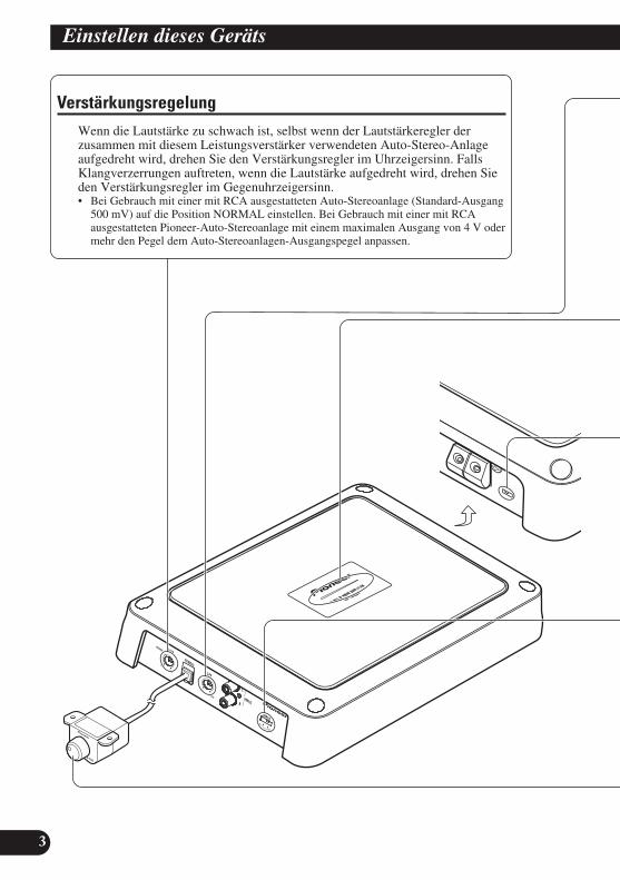
VerstärkungsregelungWenn die Lautstärke zu schwach ist, selbst wenn der Lautstärkeregler derzusammen mit diesem Leistungsverstärker verwendeten Auto-Stereo-Anlageaufgedreht wird, drehen Sie den Verstärkungsregler im Uhrzeigersinn. FallsKlangverzerrungen auftreten, wenn die Lautstärke aufgedreht wird, drehen Sieden Verstärkungsregler im Gegenuhrzeigersinn.• Bei Gebrauch mit einer mit RCA ausgestatteten Auto-Stereoanlage (Standard-Ausgang
500 mV) auf die Position NORMAL einstellen. Bei Gebrauch mit einer mit RCAausgestatteten Pioneer-Auto-Stereoanlage mit einem maximalen Ausgang von 4 V odermehr den Pegel dem Auto-Stereoanlagen-Ausgangspegel anpassen.

EN
GLIS
HES
PA
ÑO
LD
EU
TS
CH
FR
AN
ÇA
ISIT
ALIA
NO
NED
ERLA
ND
Sê
ìë
ëä
àâ
4
Interferenzschutzschalter (BFC)Verstellen Sie bitte den BFC-Schalter mittels eines kleinen Schraubendrehers, falls Sie beieingestelltem MW/LW-Sender Hintergrundgeräusche hören.
LPF (Tiefpassfilter)-Ausschaltfrequenz-RegelungSie können eine Ausschaltfrequenz zwischen 40 Hz und 240 Hz wählen.
BassverstärkungsreglerSie können den Bassverstärkungspegel zwischen 0 dB und 12 dB einstellen.Anweisungen zum Anschluss der Bassverstärkungs-Fernbedienung an den Verstärker findenSie im Abschnitt “Anschlussschema”.
Stromanzeige (Blau)Die Stromanzeige leuchtet auf, wenn die Stromversorgung eingeschaltet wird.
EingangsschalterEingang von einem externen Auto-Stereo-Ausgang oder einem Auto-Stereo-Lautsprecher-Ausgang ist möglich. Stellen Sie den Eingangsschalter ein, bevor Sie den Strom einschalten.Da Umstellen des Eingangsschalters bei eingeschaltetem Strom ein lautesLautsprechergeräusch verursachen kann, wird der Strom durch eine Schutzfunktionabgeschaltet. Zur Verwendung eines externen Ausgangs legen Sie den Schalter nach rechts(RCA). Bezüglich Anschlussanweisungen siehe Abschnitt “Anschlussschema”. ZurVerwendung eines Lautsprecher-Ausgangs legen Sie den Schalter nach links (SP). In diesemFall muss das mitgelieferte Lautsprecher-Eingangskabel mit RCA-Stiftkabel verwendet wer-den. Genaueres hierzu finden Sie im Abschnitt “Benutzung des Lautsprecher-Eingangs”.

5
Einstellen dieses Geräts
Richtige Einstellung derVerstärkung• Dieses Gerät ist mit einer Schutzfunktion
ausgestattet, die eine Betriebsstörung des Gerätsselbst und eine Beeinträchtigung der Lautsprecherwegen zu hoher Ausgangsleistung, inkorrektenGebrauchs oder fehlerhaften Anschlusses verhindert.
• Bei Ausgabe von Tonsignalen mit hoherLautstärke z.B. schaltet diese Funktion dieKlangwiedergabe nach einigen Sekunden ab. Diesist kein Anzeichen für eine Funktionsstörung. DieKlangwiedergabe normalisiert sich, sobald dieLautstärke am Hauptgerät reduziert wird.
• Wenn die Klangwiedergabe unterbrochen wird,könnte der Verstärkungsregler dieses Gerätsfalsch eingestellt sein. Um fortwährendeKlangwiedergabe bei höherer Lautstärke-Einstellung am Hauptgerät zu gewährleisten,stellen Sie den Verstärkungsregler des Verstärkersauf eine dem maximalen Preout-Ausgangspegeldes Hauptgeräts entsprechende Position ein.
Verstärkungsregler dieses Geräts
• Die obige Abbildung die auf NORMALeingestellte Verstärkung.
Die Lautstärke muss am Hauptgerät nichtreduziert werden, übermäßige Ausgängewerden kontrolliert.
Beziehung zwischenLeistungsverstärkung des Verstärkersund Ausgangsleistung des Hauptgeräts
• Wenn die Leistungsverstärkung am Verstärkerunangemessen erhöht wird, treten mehrVerzerrungen auf, während die Leistung nur ingeringem Maße gesteigert wird.
Signal-Wellenform bei Klangwiedergabemit hoher Lautstärke durchVerstärkungsregler am Verstärker
• Bei hohem Ausgang wird die Signal-Wellenformverzerrt, wenn die Leistungsverstärkung desVerstärkers erhöht wird, während die Leistungsich nur geringfügig ändert.
• Wenn auch nach Verminderung der Lautstärkeam Hauptgerät und korrekter Einstellung desVerstärkungsreglers am Verstärker noch ab undzu Tonaussetzer auftreten, wenden Sie sich bittean eine autorisierte PIONEER Kundendienststellein Ihrer Nähe.
Normale Verstärkung Maximale Verstärkung
Gleiche Leistung
Leistungsverstärkungam Verstärker (normal)
Leistungsverstärkung amVerstärker (maximal)
Signal-Wellenform
Signal-Wellenform
Normale Verstärkung Maximale Verstärkung
Leistungsverstärkungam Verstärker (normal)
Leistungsverstärkungam Verstärker (maximal)
Hauptgerät-Lautstärkestufen
Leistung Leistung
Hauptgerät-Lautstärkestufen
Gleiche Leistung
Preout-Pegel: 2 V(Standard: 500 mV)
Preout-Pegel: 4 V
Preout-Pegel: 6,5 V
Anschluss der Einheit
6
EN
GLIS
HES
PA
ÑO
LD
EU
TS
CH
FR
AN
ÇA
ISIT
ALIA
NO
NED
ERLA
ND
Sê
ìë
ëä
àâ
VORSICHT• Trennen Sie das Batterieanschlusskabel vom
negativen (–) Batteriepol, um Kurzschlüsse undSchäden am Gerät zu vermeiden.
• Befestigen Sie die Kabel mit Kabelklemmen oderKlebeband. Kabel, die Kontakt mit Metallteilenhaben, sollten an den betreffenden Stellen mitKlebeband isoliert werden.
• Vermeiden Sie beim Verlegen der Kabel Plätze,an denen die Kabel Wärmeeinwirkung ausgesetztsind, wie z.B. in der Nähe der Heizung. DerartigeWärmeeinwirkung kann zu einer Beschädigungder Kabelisolierung und schließlich zuKurzschlüssen über die Fahrzeugkarosserieführen.
• Achten Sie darauf, dass keines der Kabelbewegliche Fahrzeugteile, wie z.B. denSchalthebel, die Handbremse oder denSitzverstellhebel, behindert.
• Kürzen Sie die Kabel nicht. Gekürzte Kabelkönnen einen Ausfall der Schutzschaltungverursachen.
• Leiten Sie niemals Strom an andere Geräte,indem Sie die lsolierung desSpannungsversorgungskabels dieses Gerätesfreilegen und anzapfen. Die hieraus resultierendeÜberschreitung derSpannungsbelastungskapazität des Kabels hatÜberhitzung zur Folge.
• Ersetzen Sie die Sicherung niemals durch einemit einem größeren Wert bzw. Nennwert, als dieursprüngliche Sicherung hatte. Der Gebraucheiner falschen Sicherung kann zu Heißlauf,Rauchentwicklung, Beschädigung des Produkts,Verbrennungen und anderen Verletzungenführen.
VORSICHT:Zur Vermeidung von Schäden und/oderVerletzungen• Keinesfalls das Lautsprecherkabel direkt erden
oder einen negativen Anschluss (–) für mehrereLautsprecher gleichzeitig anschließen.
• Dieses Gerät ist für Fahrzeuge mit einer 12 VoltBatterie und negativer Erdung bestimmt. Vordem Einbau in ein Freizeitfahrzeug, Laster oderBus, die Spannung der Batterie überprüfen.
• Wenn die Autostereoanlage längere Zeiteingeschaltet bleibt, während der Motor nichtoder nur im Leerlauf läuft, so könnte dies zu einerEntladung der Batterie führen. Schalten Sie IhrStereogerät aus, wenn der Motor im Leerlauf oderim Stillstand ist.
• Sollte die System-Fernbedienungskabel desVerstärkers am Stromanschluss über denZündungsschalter angeschlossen sein(12 V Gleichspannung), so ist der Verstärkerimmer eingeschaltet, wenn die Zündungeingeschaltet wird, unabhängig davon, ob dasStereogerät ein- oder ausgeschaltet ist. In diesemFall könnte es zu einer Entladung der Batteriekommen, wenn der Motor im Stillstand oder imLeerlauf betrieben wird.
• Schließen Sie KEINEN Subwoofer mit einerniedrigeren Impedanz als im Abschnitt“Anschließen der Lautsprecherkabel” angegebenan. Ein Anschluss, der nicht den Spezifikationenentspricht, kann zu einer Beschädigung,Rauchabgabe und Überhitzung des Verstärkersführen. Außerdem kann die Oberfläche desVerstärkers heiß werden und bei Berührungleichte Verbrennungen verursachen.
• Schließen Sie einen der genannten beidenSubwoofer an den Verstärker an; 1: einenSubwoofer mit einem Nenneingang von 350 Woder höher und mit einer Impedanz von 4 Ω, oder2: einen Subwoofer mit einem Nenneingang von600 W oder höher und mit einer Impedanz von 2Ω. Wenn Nenneingang und Impedanz außerhalbdieser Bereiche liegen, kann der Subwoofer zubrennen beginnen, Rauch abgeben, oderbeschädigt werden.
• Das getrennt erhältliche Batteriekabel installierenund möglichst weit von den Lautsprecherkabelnentfernt verlegen. Getrennt erhältlichesBatteriekabel, Massekabel, Lautsprecherkabelund Verstärker möglichst weit von Antenne,Antennenkabel und Tuner entferntinstallieren/verlegen.

7
Anschluss der Einheit
Anschlussschema• Dieses Schema zeigt die Anschlüsse für externen Ausgang (Subwoofer-Ausgang). Legen Sie den
Eingangsschalter nach rechts (RCA).
6 m
Tülle Spezielles rotes Batteriekabel [RD-228] (separat erhältlich)Nachdem alle anderen Anschlüsse am Verstärker ausgeführtworden sind, das Batterie-Kabelklemme des Verstärkers mitder positiven (+) Klemme der Batterie verbinde.
Erdungskabel (schwarz) [RD-228] (separat erhältlich)An Fabrzeugkarosserie oder Metallteil anschließen.
Sicherung (30 A) × 2
Autostereo mitRCA-Ausgangsbuchsen
Externer Ausgang(Subwoofer-Ausgang)
Anschlusskabel mit RCA-Stiftsteckern (separat erhältlich).
RCA-Eingangsbuchsen
System-Fernbedienungskabel (separat erhältlich)Den Stecker dieses Kabels an die System-Fernbedienungsbuchse derAuto-Stereoanlage anschließen (SYSTEM REMOTE CONTROL). Die Buchse kann am Auto-Antennen-Relais-Anschluss angeschlossenwerden. Sollte die Stereoanlage nicht über einen Fernbedienung-System-Regler-Anschluss verfügen, schließen Sie das Steckteil amStromanschluss des Zündschalters an.
LautsprecherklemmenSiehe Abschnitt: “Anschließen derLautsprecherkabel” für Einzelheitenbezüglich des Lautsprecheranschlusses.
Buchse für die Bassverstärkungs-FernbedienungSchließen Sie das Bassverstärkungs-Fernbedienungskabel an dieseBuchse und an dieBassverstärkungs-Fernbedienungan.
Bassverstärkungs-Fernbedienung
Bassverstärkungs-Fernbedienungskabel
Sicherung (40 A) × 2
Rückseite
EN
GLIS
HES
PA
ÑO
LD
EU
TS
CH
FR
AN
ÇA
ISIT
ALIA
NO
NED
ERLA
ND
Sê
ìë
ëä
àâ
8
Lötfreie Verbindungen• Schließen Sie kein Kabel mit einer freiliegenden
Kernader an die Stromklemmen diesesVerstärkers an (Stromversorgung, GND-Anschluss, System-Fernbedienungsanschluss).Ein Abtrennen oder Zerreißen der Kernader kannzu einem Brand oder Kurzschluss führen.
• Da sich der Draht mit der Zeit lockert, muss erregelmäßig überprüft und, falls erforderlich, festgezogen werden.
• Löten oder binden Sie die Enden der verdrehtenLeiter nicht.
• Achten Sie beim Befestigen darauf, denSchutzmantel des Leiters nicht festzuklemmen.
• Verwenden Sie den mitgelieferten Inbusschlüssel,um die Klemmenschrauben des Verstärkers zulockern und festzuziehen. Sichern Sie den Drahtimmer richtig mit den Anschlussschrauben. Daein zu starkes Festziehen der Anschlussschraubender System-Fernbedienung jedoch zu einerBeschädigung des Leiters führen kann, achten Siedarauf, die Schrauben nicht zu stark festzuziehen,indem Sie beim Festziehen auf den Zustand desLeiters achten.
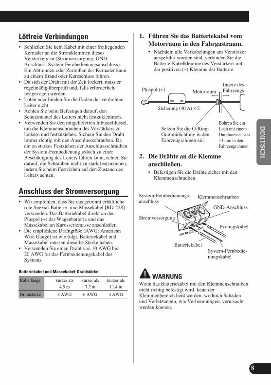
Anschluss der Stromversorgung• Wir empfehlen, dass Sie das getrennt erhältliche
rote Spezial-Batterie- und Massekabel [RD-228]verwenden. Das Batteriekabel direkt an denPluspol (+) der Wagenbatterie und dasMassekabel an Karosseriemasse anschließen.
• Die empfohlene Drahtgröße (AWG: AmericanWire Gauge) ist wie folgt. Batteriekabel undMassekabel müssen dieselbe Stärke haben.
• Verwenden Sie einen Draht von 10 AWG bis 20 AWG für das Fernbedienungskabel desSystems.
Batteriekabel und Massekabel-Drahtstärke
Kabellänge kürzer als kürzer als kürzer als
4,5 m 7,2 m 11,4 m
Drahtstärke 8 AWG 6 AWG 4 AWG
1. Führen Sie das Batteriekabel vomMotorraum in den Fahrgastraum.• Nachdem alle Verkabelungen am Verstärker
ausgeführt worden sind, verbinden Sie dieBatterie-Kabelklemme des Verstärkers mitder positiven (+) Klemme der Batterie.
2. Die Drähte an die Klemmeanschließen.• Befestigen Sie die Drähte sicher mit den
Klemmenschrauben.
WARNUNGWenn das Batteriekabel mit den Klemmenschraubennicht richtig befestigt wird, kann derKlemmenbereich heiß werden, wodurch Schädenund Verletzungen, wie Verbrennungen, verursachtwerden können.
MotorraumInnere desFahrzeugs
Bohren Sie einLoch mit einemDurchmesser von13 mm in denFahrzeugrahmen.
Setzen Sie die O-Ring-Gummidichtung in denFahrzeugrahmen ein.
Pluspol (+)
Sicherung (40 A) × 2
GND-Anschluss
Stromversorgung
Batteriekabel
System-Fernbedienungs-anschluss
System-Fernbedie-nungskabel
Erdungskabel
Klemmenschrauben

9
Anschluss der Einheit
Anschluss der Lautsprecher-Ausgang-Klemmen• Verwenden Sie einen Draht von 10 AWG bis 16
AWG für die Lautsprecherkabel.
1. Entfernen Sie den Mantel an denEnden der Lautsprecherkabel umca. 10 mm bis 12 mm mit einerKneifzange oder einem Schneider.
2. Schließen Sie die Lautsprecherkabel an dieLautsprecherausgangklemmen an.• Die Lautsprecherdrähte fest mit den
Klemmenschrauben befestigen.
Benutzung des Lautsprecher-Eingangs
Schließen Sie die Auto-Stereo-Lautsprecher-Ausgangskabel mithilfe des mitgeliefertenLautsprecher-Eingangskabels mit RCA-Stiftkabel an den Verstärker an.• Legen Sie den Eingangsschalter nach links
(SP).
7 Anschlüsse bei Benutzung desLautsprecher-Eingangs
Anschließen derLautsprecherkabel
Schließen Sie die Lautsprecherkabelgemäß folgenden Abbildungen an.
10 mm bis 12 mm
Klemmenschrauben
Lautsprecher-Ausgangklemme
Lautsprecherkabel
Lautsprecher-Ausgang
Lautsprecher-Eingangskabelmit RCA-Stiftkabel
An RCA-Eingangsbuchsedieses Geräts.
Auto-Stereo
Weiß: Schwarz: Schwarz: Rot:Links + Links ≠ Rechts ≠ Rechts +
Subwoofer

EN
GLIS
HES
PA
ÑO
LD
EU
TS
CH
FR
AN
ÇA
ISIT
ALIA
NO
NED
ERLA
ND
Sê
ìë
ëä
àâ
10
VORSICHT• Keinesfalls an Orten einbauen:
—Plätze, an denen sich der Fahrer oder dieFahrzeuginsassen bei plötzlichem Abbremsenam Gerät verletzen könnten.
—Plätze, an denen das Gerät den Fahrer behin-dern könnte, wie z.B. auf dem Boden vor derFahrersitz.
• Achten Sie darauf, dass sich die Anschlusskabelnicht im Schiebemechanismus der Sitzeverklemmen und auf diese Weise einen Kurzschlussverursachen.
• Bestätigen Sie vor dem Bohren, dass sich hinter derKonsole keine Teile befinden, die nicht beschädigtwerden dürfen. Schützen Sie alle Kabel undwichtigen Teile wie Benzinleitungen undBremsleitungen und elektrischen Leitungen vorSchäden.
• Bringen Sie Schneidschrauben so an, dass dieSchraubenspitze keines der Kabel berührt.Andernfalls können die Kabel durch die Vibrationendes Fahrzeugs beschädigt werden und Brändeverursachen.
• ACHTEN Sie darauf, dass der Verstärker NICHTmit Flüssigkeiten in Berührung kommen kann, zumBeispiel wegen eines ungünstigen Einbauplatzes.Ein elektrischer Schlag könnte die Folge sein.Berührung mit Flüssigkeiten kann auch zu einerBeschädigung von Verstärker und Lautsprechern,sowie zu Rauchbildung und Überhitzung führen.Außerdem können Oberflächen von Verstärker undjeglicher angebrachter Lautsprecher heiß werden,sodass bei Berührung kleinere Verbrennungenverursacht werden könnten.
• Um einen ordnungsgemäßen Einbau zugewährleisten, verwenden Sie die mitgeliefertenTeile wie spezifiziert. Falls andere Teile außer denspezifizierten verwendet werden, so könnten innereTeile des Verstärkers beschädigt werden oder diesekönnten sich lösen, und der Verstärker sichausschalten.
• Ersetzen Sie die Sicherung niemals durch eine miteinem größeren Wert bzw. Nennwert, als dieursprüngliche Sicherung hatte. Der Gebrauch einerfalschen Sicherung kann zu Heißlauf,Rauchentwicklung, Beschädigung des Produkts,Verbrennungen und anderen Verletzungen führen.
VORSICHT:Zur Vermeidung von Funktionsstörungenund/oder Verletzungen• Beachten Sie zur Gewährleistung ausreichender
Wärmeableitung beim Einbau die folgende Punkte.—Lassen Sie genügend Freiraum über dem
Verstärker, damit richtige Ventilationgewährleistet ist.
—Decken Sie den Verstärker nicht mit einerBodenmatte oder einem Teppich ab.
• ACHTEN Sie darauf, dass der Verstärker NICHTmit Flüssigkeiten in Berührung kommen kann,zum Beispiel wegen eines ungünstigenEinbauplatzes. Ein elektrischer Schlag könnte dieFolge sein. Berührung mit Flüssigkeiten kannauch zu einer Beschädigung von Verstärker undLautsprechern, sowie zu Rauchbildung undÜberhitzung führen. Außerdem könnenOberflächen von Verstärker und jeglicherangebrachter Lautsprecher heiß werden, sodassbei Berührung kleinere Verbrennungenverursacht werden könnten.
• Bauen Sie den Verstärker nicht an unstabilenPlätzen ein, wie z.B. auf dem Ersatzreifenhalter.
• Die beste Einbauposition ist je nach Autotypunterschiedlich. Befestigen Sie den Verstärker aneinem sicheren Platz.
• Führen Sie vorrübergehende Anschlüsse zuerstdurch, und stellen Sie sicher, dass der Verstärkerund das System sicher funktionieren.
• Achten Sie nach dem Einbau des Verstärkersdarauf, dass Ersatzreifen, Wagenheber undWerkzeuge noch leicht zugänglich sind.
Einbau

11
Einbau
Befestigen der Fernbedienung fürdie BassverstärkungBefestigen Sie die beiden Blechschrauben (3 mm ×10 mm) an einem leicht zugänglichen Ort, beispiel-sweise unter dem Armaturenbrett.
Beispiel eines Einbaus auf einerBodenmatte oder auf dem Rahmen1. Legen Sie den Verstärker auf die
Stelle, an welcher dieser eingebautwerden soll. Setzen Sie diemitgelieferen Schneidschrauben (4 mm × 18 mm) in dieSchraubenlöcher ein. Drücken Siedie Schrauben mit einemSchraubenzieher, sodass dieseMarkierungen hinterlassen, wodiese eingesetzt werden sollen.
2. Bohren Sie Löcher mit einemDurchmesser von 2,5 mm an denzuvor markierten Punkten, undbringen Sie den Verstärker an,entweder direkt am Teppich oderam Rahmen.
Blechschraube (3 mm × 10 mm)
Bohren Sie ein Loch mit einemDurchmesser von 2,5 mm
Schneidschraube(4 mm × 30 mm)
Boden-matteoderRahmen

EN
GLIS
HES
PA
ÑO
LD
EU
TS
CH
FR
AN
ÇA
ISIT
ALIA
NO
NED
ERLA
ND
Sê
ìë
ëä
àâ
12
Stromversorgung ............................................................................ 14,4 V Gleichspannung (Toleranz 10,8 V bis 15,1 V)Erdungssystem ........................................................................................................................................................ NegativLeistungsaufnahme .......................................................................................... 27,0 A (bei gleichbleibendem Strom, 4 Ω)Durchschnittliche Stromentnahme* ............................................................................................ 7,5 A (4 Ω für ein Kanal)
15,0 A (2 Ω für ein Kanal)Sicherung ................................................................................................................................................................ 30 A × 2Abmessungen ...................................................................................................... 290 mm (B) × 56 mm (H) × 200 mm (T)
(Außer den Klemmen)Gewicht ...................................................................................................................... 3,2 kg (Kabel nicht eingeschlossen)Max. Ausgangsleistung ............................................................................................ 600 W × 1 (4 Ω) / 1 200 W × 1 (2 Ω)Dauerleistung (14,4 V) ........................................................................ 4 Ω, 20 Hz bis 240 Hz, 1,0 % THD, 300 W × 1
2 Ω, 50 Hz, 1,0 % THD, 600 W × 1Verbraucher-Impedanz .............................................................................................................. 4 Ω (2 Ω bis 8 Ω zulässig)Frequenzgang .................................................................................................................. 10 Hz bis 240 Hz (+0 dB, –3 dB)Signalrauschabstand ............................................................................................................................ 80 dB (IEC-A-Netz)Verzerrungen .................................................................................................................................... 0,3% (10 W, 100 Hz)Tiefpassfilter .................................................................................................................. Trennfrequenz: 40 Hz bis 240 Hz
Trennkurve: –12 dB/octBassverstärkungt ........................................................................................................................................ Frequenz: 50 Hz
Pegel: 0 dB bis 12 dBVerstärkungsregelung .................................................................................................................. RCA: 200 mV bis 6,5 V
Lautsprecher: 0,8 V bis 26 VMax. Eingangsstufe / Impedanz .......................................................................................................... RCA: 6,5 V / 22 kΩ
Lautsprecher: 26 V / 90 kΩ
Hinweis:• Änderungen der technischen Daten und des Designs jederzeit vorbehalten.
*Durchschnittliche Stromentnahme• Die durchschnittliche Stromentnahme entspricht fast der maximalen
Stromentnahme dieses Gerätes, wenn ein Audiosignal eingegeben wird.Verwenden Sie diesen Wert, wenn Sie die Gesamtstromentnahmen für mehrereLeistungsverstärker berechnen wollen.
Technische Daten

1
Avant d’utiliser cet appareil .................... 1Visitez notre site Web ...................................... 1En cas d’anomalie ............................................ 2Quelques mots concernant cet appareil ............ 2PRÉCAUTION .................................................. 2ATTENTION .................................................... 2
Réglage de l’appareil ................................ 3Commande du gain ............................................ 3Commande de la fréquence de coupure LPF
(Filtre passe-bas) ........................................ 4Témoin d’alimentation (Bleu) .......................... 4Interrupteur BFC (Commande de fréquence
de battement) .............................................. 4Sélecteur d’entrée .............................................. 4Commande de l’accentuation des graves .......... 4Réglage correct du gain .................................... 5
Raccordement de l’appareil .................... 6Schéma de raccordement .................................. 7Prise de connexion sans soudure ...................... 8Raccordement de la borne d’alimentation ........ 8Raccordement des bornes de sortie vers
les haut-parleurs ........................................ 9Utilisation de l’entrée de haut-parleur .............. 9Connexion des câbles des haut-parleurs ............ 9
Installation ................................................ 10Fixation de la télécommande d’accentuation
des graves ................................................ 11Exemple d’installation sur le tapis de sol
ou sur le châssis ........................................ 11
Caractéristiques techniques ................ 12
Nous vous remercions d’avoir acheté cetappareil PIONEER. Avant de l’utiliser,prendre soin de lire ce manuel.
Les habitants des états membres de l’UE,de Suisse et de Norvège peuvent retournergratuitement leurs appareils électroniquesusagés aux centres de collecte agréés ou àun détaillant (si vous rachetez un appareilsimilaire neuf).Dans les pays qui ne sont pas mentionnés ci-dessus, veuillez contacter les autoritéslocales pour savoir comment vous pouvezvous débarrasser de vos appareils.Vous garantirez ainsi que les appareilsdont vous vous débarrassez sontcorrectement récupérés, traités et recycléset préviendrez de cette façon les impactsnéfastes possibles sur l’environnement etla santé humaine.
Visitez notre site WebRendez-nous visite sur le site suivant:http://www.pioneer.fr• Enregistrez votre produit. Nous con-
serverons sur fichier les détails de votreachat pour vous permettre de vousreporter à ces informations en cas dedéclaration à votre assurance pour perteou vol.
• Notre site Web fournit les informationsles plus récentes sur la PioneerCorporation.
Si vous souhaitez vousdébarrasser de cet appareil, nele mettez pas à la poubelleavec vos ordures ménagères.Il existe un système decollecte séparé pour lesappareils électroniquesusagés, qui doivent êtrerécupérés, traités et recyclésconformément à lalégislation.
Table des matières Avant d’utiliser cet appareil
EN
GLIS
HES
PA
ÑO
LD
EU
TS
CH
FR
AN
ÇA
ISIT
ALIA
NO
NED
ERLA
ND
Sê
ìë
ëä
àâ
2
En cas d’anomalieEn cas d’anomalie de fonctionnement,veuillez consulter le distributeur ou le centre d’entretien PIONEER le plusproche.
Quelques mots concernant cet appareil
Cet appareil est un amplificateur de classeD pour haut-parleur d’extrême grave. Siles deux canaux, L (gauche) et R (droit),sont connectés à l’entrée cinch (RCA) decet appareil, la sortie est mixée parce quecet appareil est un amplificateur monaural.
PRÉCAUTION• Ne remplacez pas le fusible par un fusible de plus
grande valeur ou de plus grand calibre.L’utilisation d’un fusible inadapté peut entraînerune surchauffe et de la fumée, et peut provoquerl’endommagement de l’appareil et des blessures,y compris des brûlures.
• Utilisez la clé hexagonale fournie pour serrer lesvis lors de la fixation des câbles sur la borne.L’utilisation d’une longue clé hexagonale en ventedans le commerce peut entraîner l’application d’uncouple de serrage excessif et endommager lesbornes et les câbles.
ATTENTION• Nous recommandons que vous utilisiez le
faisceau de câbles de liaison à la batterie (uncâble rouge et un câble de masse) qui est venduséparément [RD-228]. Reliez le câble rouge à laborne positive (+) de la batterie et le câble demasse à la carrosserie du véhicule.
• Ne touchez pas l’amplificateur quand vous avezles mains mouillées, faute de quoi vous risquezde ressentir une secousse électrique. Pareillement,ne touchez pas l’amplificateur s’il est mouillé.
• Pour votre sécurité et celles des autres usagers dela route, maintenez le niveau d’écoute à unevaleur telle que les bruits de la circulationdemeurent nettement perceptibles.
• Si le fusible monté sur le câble de liaison à labatterie, câble qui est vendu séparément, a grilléou bien s’il en est ainsi de celui del’amplificateur, vérifiez soigneusement toutes lesconnexions d’alimentation et du haut-parleurd’extrême grave. Recherchez la cause del’anomalie puis corrigez-la; enfin, remplacez lefusible grillé par un fusible de même taille et demême calibre.
• Pour éviter d’endommager l’amplificateur et duhaut-parleur d’extrême grave, le circuit deprotection coupe l’alimentation de l’amplificateur(les sons ne sont plus émis) dès que survient unesituation anormale. Dans ce cas, mettezl’ensemble des appareils hors tension et contrôlezles liaisons entre l’amplificateur et du haut-parleur d’extrême grave. Le cas échéant,recherchez la cause de l’anomalie et corrigez-la.
• Consultez le revendeur si vous n’êtes pas enmesure de résoudre le problème qui se pose àvous.
• Pour éviter toute secousse électrique et toutrisque de court-circuit au cours des opérations de raccordement et d’installation, n’oubliez pas dedébrancher le câble relié au pôle négatif de labatterie (–) avant d’effectuer quelque opérationque ce soit.
• Avant d’effectuer un perçage requis parl’installation de l’amplificateur, assurez-vous quevous pouvez le faire sans danger pour les câbles,canalisations, flexibles, etc., qui sont placésderrière le panneau que vous devez percer.
• NE LAISSEZ PAS l’amplificateur entrer encontact avec des liquides à cause, par exemple, del’emplacement où il a été placé. Cela pourraitentraîner une secousse électrique. De plus, lecontact avec un liquide pourrait endommagerl’amplificateur et les enceintes, produire de lafumée ou surchauffer l’appareil. Enfin, la surfacede l’amplificateur et des enceintes connectéespeut devenir chaude au toucher et entraîner delégères brûlures.

3
Réglage de l’appareil
Commande du gainSi le niveau d’écoute est faible même lorsque la commande de l’autoradio estsur la position correspondant au maximum, tournez la commande de gain dansle sens des aiguilles d’une montre. Inversement, si vous constatez de ladistorsion lorsque vous augmentez le niveau de sortie de l’autoradio, tournezcette commande dans le sens contraire des aiguilles d’une montre.• Choisissez la position NORMAL si l’autoradio stéréo est équipé de prises Cinch
(RCA) (niveau de sortie standard à 500 mV). Si cet appareil est utilisé conjointementavec un autoradio stéréo Pioneer pourvu de prises Cinch (RCA) sur lesquelles peuventse trouver une tension de sortie de 4 V ou plus, réglez le niveau en fonction du niveaude sortie de l’autoradio.

EN
GLIS
HES
PA
ÑO
LD
EU
TS
CH
FR
AN
ÇA
ISIT
ALIA
NO
NED
ERLA
ND
Sê
ìë
ëä
àâ
4
Interrupteur BFC (Commande de fréquence de battement) Si l’on entend un battement pendant que l’on écoute une transmission MW/LW (PO/GO)avec le stéréo de la voiture, changer l’interrupteur BFC en utilisant un petit tournevis stan-dard de pointe.
Commande de la fréquence de coupure LPF (Filtre passe-bas)La fréquence de coupure peut être choisie entre 40 Hz et 240 Hz.
Commande de l’accentuation des gravesVous pouvez ajuster le niveau d’accentuation entre 0 dB et 12 dB.Pour connaître la manière de relier le boîtier de télécommande d’accentuation des graves àl’amplificateur, reportez-vous à la section “Schéma de raccordement”.
Témoin d’alimentation (Bleu)Ce témoin s’éclaire lorsque l’amplificateur est sous tension.
Sélecteur d’entréeIl est possible d’entrer des signaux à partir de la sortie extérieure d’un autoradio ou de la sortied’enceinte d’un autoradio. Réglez le sélecteur d’entrée avant de mettre l’appareil sous tension.Une fonction de protection met l’appareil hors tension si vous essayez de régler le sélecteurquand l’appareil est sous tension car sinon un son fort pourrait être émis des haut-parleurs. Lorsde l’utilisation d’une sortie extérieure, faites glisser le sélecteur sur la droite (RCA). Pour lesinstructions de connexion, reportez-vous à la section “Schéma de raccordement”. Lors del’utilisation de la sortie de haut-parleur, faites glisser le sélecteur sur la gauche (SP). Dans cecas, il est nécessaire d’utiliser le cordon d’entrée de haut-parleur muni de fiches Cinch (RCA)fourni. Pour les détails, reportez-vous à la section “Utilisation de l’entrée de haut-parleur”.

5
Réglage de l’appareil
Réglage correct du gain• Cet appareil est muni d’une fonction de protection
qui protège l’appareil et les enceintes de toutmauvais fonctionnement dû à une utilisationincorrecte ou à une connexion incorrecte.
• Quand le son est sorti à un niveau de volumeélevé, etc. cette fonction coupe la sortie du son enquelques secondes. Ce n’est pas un mauvais fonc-tionnement. Si vous baissez le niveau de volumede l’appareil principal, la sortie du son estrétablie.
• Si la sortie du son est coupée, c’est peut-êtreparce que la commande de gain de cet appareil estréglée incorrectement. Pour assurer une sortiecontinue du son même quand le niveau de volumede l’appareil principal est augmenté, réglez lacommande du gain de l’amplificateur sur uneposition correcte en fonction du niveau de sortiemaximum préamplifié de l’appareil principal.
Commande du gain de cet appareil
• L’illustration ci-dessus montre le réglage du gainsur NORMAL.
Il n’est pas nécessaire de diminuer le volumede l’appareil principal et quand la sortie esttrop forte.
Relation entre le gain de l’amplificateuret la puissance de sortie de l’appareilprincipal
• Si vous augmentez le gain de l’amplificateur à unniveau incorrect, seule la distorsion est augmentéeet la puissance n’augmente que légèrement.
Forme de signal quand la puissance desortie est élevée par la commande gain del’amplificateur
• Quand la puissance de sortie est élevée, la formede signal est déformée et si vous augmentez legain de l’amplificateur la puissance n’augmenteque légèrement.
• Si vous diminuez le volume de l’appareil princi-pal et réglez la commande de gain de l’amplifica-teur sur la position correcte mais que le son con-tinue à être coupé de temps à autre, contactez lecentre de service autorisé PIONEER le plusproche.
Puissance égale
Gain de l’amplificateur(normal)
Gain de l’amplificateur(maximum)
Forme designal
Forme designal
Gain normal Gain maximum
Gain de l’amplificateur(normal)
Gain de l’amplificateur(maximum)
Augmentation du volumede l’appareil principal
PuissanceGain normal
Puissance
Augmentation du volumede l’appareil principal
Gain maximum
Puissance égale
Niveau depréamplification: 2 V(Standard: 500 mV)
Niveau de préamplification: 4 V
Niveau de préamplification: 6,5 V

Raccordement de l’appareil
6
EN
GLIS
HES
PA
ÑO
LD
EU
TS
CH
FR
AN
ÇA
ISIT
ALIA
NO
NED
ERLA
ND
Sê
ìë
ëä
àâ
PRÉCAUTION• Pour éviter tout risque de court-circuit ou
d’endommager cet appareil, débranchez le câblerelié à la borne négative (–) de la batterie, auniveau de cette borne.
• Fixez les câbles au moyen de colliers ou du rubanadhésif. Lorsque l’isolant du câble peut êtreendommagé par une pièce métallique, assurez saprotection en le gainant de ruban adhésif.
• Faites cheminer les câbles en évitant les zoneschaudes telles que les bouches du chauffage. La chaleur peut endommager l’isolant et il peuten résulter un court-circuit si l’âme du câble vienten contact avec la carrosserie.
• Assurez-vous que les câbles ne gênent en rien lamanoeuvre des organes mobiles tels que rails desiège mais aussi levier de frein de stationnement,pédale de frein, etc.
• Veillez à ce qu’aucun câble ne soit en court-circuit, faute de quoi le circuit de protectionpourrait être dans l’incapacité de remplir sonoffice.
• N’alimentez pas un appareil par un piquage sur lecâble qui alimente un autre appareil. Ce câble n’apeut-être pas la section suffisante pour supportersans danger l’intensité consommée par les deuxappareils.
• Ne remplacez pas le fusible par un fusible de plusgrande valeur ou de plus grand calibre.L’utilisation d'un fusible inadapté peut entraînerune surchauffe et de la fumée, et peut provoquerl’endommagement de l’appareil et des blessures,y compris des brûlures.
PRÉCAUTION:Pour éviter toute anomalie ou blessure• Ne reliez pas à la masse le câble (–) d’un
haut-parleur; ne reliez pas ensemble plusieurscâbles négatifs de haut-parleurs.
• Cet appareil est conçu pour les véhiculesalimentés par une batterie 12 V dont le pôlenégatif est à la masse. Avant d’installer cetappareil, contrôlez la tension de la batterie.
• Si vous conservez l’autoradio en fonctionnementalors que le moteur est arrêté ou tourne au ralenti,la batterie peut être déchargée au bout d’uncertain temps. Pour éviter cela, mettez l’autoradiohors tension.
• Si le câble de commande à distance del’amplificateur est relié à la borne d’alimentationpar l’intermédiaire du contacteur d’allumage (12V CC), l’amplificateur sera sous tension dès quevous mettrez le contact, et cela quelle que soit lasituation de l’autoradio. En conséquence, labatterie peut être rapidement déchargée si lemoteur ne tourne pas, ou tourne au ralenti.
• NE RACCORDEZ PAS un haut-parleurd’extrêmes graves dont l’impédance seraitinférieure à celle prescrite dans la section“Connexion des câbles des haut-parleurs”. Il pourrait en résulter un endommagement del’amplificateur, voire de la production de fuméeaccompagnée de surchauffe. La surface del’amplificateur pourrait s’échauffer au point decauser des brûlure légères.
• Reliez l’un de ces deux caissons de graves àl’amplificateur; 1: un caisson de graves ayant unepuissance admissible de 350 W ou mieux et uneimpédance de 4 Ω, ou 2: un caisson de gravesayant une puissance admissible de 600 W oumieux et une impédance de 2 Ω. Si l’entréenominale et l’impédance sont au-dessus de cesplages, le haut-parleur d’extrême grave risque deprendre feu, d’émettre de la fumée ou d’êtreendommagé.
• Installez le câble de liaison à la batterie, venduséparément, et faites-le cheminer aussi loin quepossible des câbles de liaison aux haut-parleurs.Installez le câble de liaison à la batterie, venduséparément, le câble de masse, les câbles deliaison aux haut-parleurs et l’amplificateur aussiloin que possible de l’antenne, du câble d’antenneet du syntoniseur.

7
Raccordement de l’appareil
Schéma de raccordement• Ce schéma montre les connexions en utilisant une sortie extérieure (sortie de haut-parleur d’extrêmes
graves). Faites glisser le sélecteur d’entrée sur la droite (RCA).
6 m
Câble rouge de liaison à la batterie [RD-228] (vendu séparément)Après avoir effectué tous les autres raccordements de l’amplificateur, reliez ce câble à la borne positive (+) de labatterie.
Câble de masse (noir) [RD-228] (vendu séparément)Reliez ce câble à la carrosserie du véhicule.
Passe-câblecaoutchouté
Fusible (30 A) × 2
Prises d’entrée Cinch (RCA)
Borne des haut-parleurReportez-vous à la section “Connexion descâbles des haut-parleurs”.
Câble de commande à distance d’alimentation (vendu séparément)Reliez la fiche mâle de ce câble à la borne de commande à distance del’autoradio (SYSTEM REMOTE CONTROL). La fiche femelle doit êtrereliée à la prise de commande de l’antenne motorisée. Si l’autoradio nepossède par de prise pour commande à distance de la mise sous tension,reliez la fiche mâle à une borne d’alimentation en passant par le contacteurd’allumage.
Prises Cinch(RCA) de sortiede l’autoradio
Sortie extérieure(sortie de haut-parleurd’extrême grave)
Câble de liaison munis de prisesCinch (RCA) (vendus séparément).
Prise pour la télécommanded’accentuation des gravesReliez cette prise et le boîtier detélécommande d’accentuationdes graves au moyen d’un câblede télécommande.
Télécommande d’accentuation des graves
Câble de télécommande d’accentuation des graves
Fusible (40 A) × 2
Autre face

EN
GLIS
HES
PA
ÑO
LD
EU
TS
CH
FR
AN
ÇA
ISIT
ALIA
NO
NED
ERLA
ND
Sê
ìë
ëä
àâ
8
Prise de connexion sans soudure• Ne connectez pas un câble dont l’âme est à nu à
la borne d’alimentation de cet amplificateur(Borne d’alimentation, borne de masse (GND),Borne de commande à distance d’alimentation).Une déconnexion ou une coupure de l’âme ducâble peut être la cause d’un incendie ou d’uncourt-circuit.
• Comme le câble devient lâche avec le temps, ildoit être vérifié périodiquement et resserré sinécessaire.
• Ne soudez ni ne tordez les extrémités des âmestorsadées.
• Serrez en vous assurant de ne pas coincer la gaineisolante du câble.
• Utilisez la clé hexagonale fournie pour serrer etdesserrer la vis de la prise de l’amplificateur.Serrez le câble solidement avec la vis de la prise.Cependant, faites attention de ne pas serrer exces-sivement en contrôlant l’état du câble pendant leserrage car un serrage excessif de la vis de laprise du système de commande à distance peutendommager le câble.
Raccordement de la borne d’alimentation• Nous recommandons que vous utilisiez le fais-
ceau de câbles de liaison à la batterie (un câblerouge et un câble de masse) qui est vendu séparé-ment [RD-228]. Reliez le câble rouge à la bornepositive (+) de la batterie et le câble de masse à lacarrosserie du véhicule.
• La section conseillée des câbles est la suivante(suivant AWG, American Wire Gauge). Le câblede batterie et le câble de masse doivent avoir lamême section.
• Utilisez un câble de 10 AWG à 20 AWG pour lecâble de commande à distance d’alimentation.
Section de câble de la batterie et câble de masse
Longueur du moins de moins de moins decâble 4,5 m 7,2 m 11,4 m
Section du câble 8 AWG 6 AWG 4 AWG
1. Faites passer le câble de liaison à labatterie du compartiment moteurvers l’intérieur du véhicule.• Après avoir effectué tous les autres raccorde-
ments de l’amplificateur, reliez la borne d’alimentation de l’amplificateur à la bornepositive (+) de la batterie.
2. Reliez les câbles aux bornes.• Serrez soigneusement les câbles au moyen
des vis.
ATTENTIONFaute de serrer soigneusement le câble de batteriesur la borne au moyen d’une vis de borne, uneélévation importante de température de la borne peutse produire et provoquer dommages et blessures, ycompris brûlures légères.
Compartimentmoteur
Intérieur duvéhicule
Percez untrou de 13mm dans letablier.
Engagez le passe-câble encaoutchouc dans le perçagepour assurer la protection ducâble.
Bornepositive (+)
Fusible (40 A) × 2
Borne de masse(GND)
Borne d’alimentation
Câble de la batterie
Borne de commande àdistance d’alimentation
Câble de commandeà distanced’alimentation
Câble de masse
Vis de borne
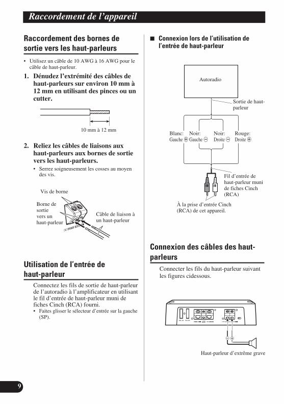
9
Raccordement de l’appareil
Raccordement des bornes de sortie vers les haut-parleurs• Utilisez un câble de 10 AWG à 16 AWG pour le
câble de haut-parleur.
1. Dénudez l’extrémité des câbles dehaut-parleurs sur environ 10 mm à12 mm en utilisant des pinces ou uncutter.
2. Reliez les câbles de liaisons auxhaut-parleurs aux bornes de sortievers les haut-parleurs.• Serrez soigneusement les cosses au moyen
des vis.
Utilisation de l’entrée de haut-parleur
Connectez les fils de sortie de haut-parleurde l’autoradio à l’amplificateur en utilisantle fil d’entrée de haut-parleur muni defiches Cinch (RCA) fourni.• Faites glisser le sélecteur d’entrée sur la gauche
(SP).
7 Connexion lors de l’utilisation del’entrée de haut-parleur
Connexion des câbles des haut-parleurs
Connecter les fils du haut-parleur suivantles figures cidessous.
10 mm à 12 mm
Vis de borne
Borne de sortie vers un haut-parleur
Câble de liaison àun haut-parleur
Sortie de haut-parleur
Fil d’entrée dehaut-parleur munide fiches Cinch(RCA)
À la prise d’entrée Cinch(RCA) de cet appareil.
Autoradio
Blanc: Noir: Noir: Rouge:Gauche + Gauche ≠ Droite ≠ Droite +
Haut-parleur d’extrême grave

EN
GLIS
HES
PA
ÑO
LD
EU
TS
CH
FR
AN
ÇA
ISIT
ALIA
NO
NED
ERLA
ND
Sê
ìë
ëä
àâ
10
PRÉCAUTION• N’installez pas l’appareil:
—dans un endroit où il pourrait blesser unoccupant du véhicule en cas d’arrêt brusque;
—dans un endroit où il pourrait gêner leconducteur, par exemple devant son siège.
• Veillez à ce que les câbles ne puissent pas êtrepincés et endommagés par les sièges, ce qui peutconduire à un court-circuit.
• Avant d’effectuer un perçage requis parl’installation de l’amplificateur, assurez-vous quevous pouvez le faire sans danger pour les câbles,canalisations, flexibles, etc., qui sont placésderrière le panneau que vous devez percer.
• Posez les vis autotaraudeuses de manière que leurextrémité ne puisse pas endommager les câbles. Ilest important que l’isolant d’un câble ne soit pasendommagé par le frottement sur une pièce, cequi pourrait ultérieurement entraîner un court-circuit.
• NE LAISSEZ PAS l’amplificateur entrer encontact avec des liquides à cause, par exemple, del’emplacement où il a été placé. Cela pourraitentraîner une secousse électrique. De plus, lecontact avec un liquide pourrait endommagerl’amplificateur et les enceintes, produire de lafumée ou surchauffer l’appareil. Enfin, la surfacede l’amplificateur et des enceintes connectéespeut devenir chaude au toucher et entraîner delégères brûlures.
• Pour effectuer convenablement l’installation,utilisez les pièces fournies et procédez comme ilest indiqué. L’utilisation de pièces autres quecelles fournies peut endommager l’amplificateur.
• Ne remplacez pas le fusible par un fusible de plusgrande valeur ou de plus grand calibre.L’utilisation d'un fusible inadapté peut entraînerune surchauffe et de la fumée, et peut provoquerl’endommagement de l’appareil et des blessures,y compris des brûlures.
PRÉCAUTION:Pour éviter toute anomalie de fonctionnement ou blessure• Pour que la chaleur puisse se dissiper sans mal,
respectez ce qui suit:—veillez à ce qu’un espace dégagé existe au-
dessus de l’amplificateur;—ne recouvrez pas l’amplificateur d’un tapis
ou d’une moquette.• NE LAISSEZ PAS l’amplificateur entrer en
contact avec des liquides à cause, par exemple, del’emplacement où il a été placé. Cela pourraitentraîner une secousse électrique. De plus, le contact avec un liquide pourraitendommager l’amplificateur et les enceintes,produire de la fumée ou surchauffer l’appareil.Enfin, la surface de l’amplificateur et desenceintes connectées peut devenir chaude autoucher et entraîner de légères brûlures.
• N’installez pas l’amplificateur sur une surfaceinstable telle que le tapis amovible cachant laroue de secours.
• Le meilleur emplacement d’installation dépenddu véhicule, mais, quoi qu’il en soit, doit êtrerigide et solide.
• Effectuez tout d’abord des raccordementstemporaires pour vous assurer que l’amplificateuret les autres appareils fonctionnent correctement.
• Choisissez un emplacement qui permette le retraitsans peine de la roue de secours, du cric et de laboîte à outils.
Installation

11
Installation
Fixation de la télécommanded’accentuation des gravesFixez-la avec les vis autotaraudeuses (3 mm ×10 mm) dans un endroit facile d’accès tel que sous letableau de bord.
Exemple d’installation sur le tapisde sol ou sur le châssis
1. Posez l’amplificateur àl’emplacement choisi. Introduisezles vis autotaraudeuses fournies (4 mm × 18 mm) dans les perçages.Appuyez fermement sur les vis aumoyen d’un tournevis pourmarquer les points de perçage.
2. Percer des trous de 2,5 mm dediamètre aux emplacementsmarqués puis fixez l’amplificateursoit à travers le tapis, soitdirectement sur le châssis.
Vis autotaraudeuse(3 mm × 10 mm)
Percer un trou de 2,5 mm dediamètre
Vis autotaraudeuse (4 mm × 30 mm)
Tapis ouchâssis
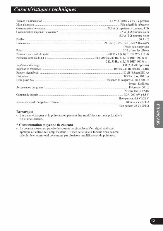
EN
GLIS
HES
PA
ÑO
LD
EU
TS
CH
FR
AN
ÇA
ISIT
ALIA
NO
NED
ERLA
ND
Sê
ìë
ëä
àâ
12
Tension d’alimentation .............................................................................................. 14,4 V CC (10,8 V à 15,1 V permis)Mise à la masse ............................................................................................................................ Pôle négatif de la batterieConsommation de courant ........................................................................................ 27,0 A (à la puissance continue, 4 Ω)Consommation moyenne de courant* ........................................................................................ 7,5 A (4 Ω pour une voie)
15,0 A (2 Ω pour une voie)Fusible .................................................................................................................................................................... 30 A × 2Dimensions .......................................................................................................... 290 mm (L) × 56 mm (H) × 200 mm (P)
(Prises non comprises)Poids ................................................................................................................................................ 3,2 kg (sans les câbles)Puissance maximale de sortie .................................................................................. 600 W × 1 (4 Ω) / 1 200 W × 1 (2 Ω)Puissance continue (14,4 V) .................................................................... 4 Ω, 20 Hz à 240 Hz, 1,0 % DHT, 300 W × 1
2 Ω, 50 Hz, 1,0 % DHT, 600 W × 1Impédance de charge ...................................................................................................................... 4 Ω (2 Ω à 8 Ω permis)Réponse en fréquence ........................................................................................................ 10 Hz à 240 Hz (+0 dB, –3 dB)Rapport signal/bruit ........................................................................................................................ 80 dB (Réseau IEC-A)Distorsion .......................................................................................................................................... 0,3 % (10 W, 100 Hz)Filtre passe-bas ...................................................................................................... Fréquence de coupure: 40 Hz à 240 Hz
Pente: –12 dB/octAccentuation des graves .......................................................................................................................... Fréquence: 50 Hz
Niveau: 0 dB à 12 dBCommande du gain .......................................................................................................................... RCA: 200 mV à 6,5 V
Haut-parleur: 0,8 V à 26 VNiveau maximale / impédance d’entrée .............................................................................................. RCA: 6,5 V / 22 kΩ
Haut-parleur: 26 V / 90 kΩ
Remarque:• Les caractéristiques et la présentation peuvent être modifiées sans avis préalable à
fin d’amélioration.
* Consommation moyenne de courant• Le courant moyen est proche du courant maximal lorsqu’un signal audio est
appliqué à l’entrée de l’amplificateur. Utilisez cette valeur lorsque vous désirezcalculer le courant total consommé par plusieurs amplificateurs de puissance.
Caractéristiques techniques
1
Prima di usare questo prodotto .............. 1Visita il nostro sito Web .................................... 1In caso di difficotà ............................................ 2A proposito del prodotto .................................... 2PRECAUZIONE ................................................ 2ATTENZIONE .................................................. 2
Regolazione di questa unità .................... 3Comando del guadagno .................................... 3Commando della soglia della frequenza
di taglio LPF (filtro passa-basso) .............. 4Indicatore dell’alimentazione (Blu) .................. 4Commutatore BFC (Comando della
frequenza di battimento) ............................ 4Selettore d’ingresso .......................................... 4Comando di selezione per
l’espansione dei bassi ................................ 4Regolazione corretta del guadagno .................... 5
Come collegare I’unità .............................. 6Schema di collegamento .................................... 7Collegamenti senza saldatura ai terminali ........ 8Come collegare il terminale
dell’alimentazione ...................................... 8Come collegare il terminale di uscita degli
altoparlanti .................................................. 9Utilizzo dell’ingresso altoparlanti .................... 9Collegamento dei cavi d’altoparlanti ................ 9
Installazione ............................................ 10Fissaggio del telecomando di potenziamento
dei bassi .................................................... 11Esempio dell’installazione sul pavimento
oppure sullo chassis .................................. 11
Caratteristiche .......................................... 12
Grazie per aver acquistato questo prodottoPIONEER. Leggere attentamente questeistruzioni prima di usare questoapparecchio.
I privati cittadini dei paesi membridell’UE, di Svizzera e Norvegia, possonorestituire senza alcun costo i loro prodottielettronici usati ad appositi servizi diraccolta o a un rivenditore (se si desideraacquistarne uno simile).Per i paesi non citati qui sopra, si pregadi prendere contatto con le autorità localiper il corretto metodo di smaltimento.In questo modo, si è sicuri che il proprioprodotto eliminato subirà il trattamento,il recupero e il riciclo necessari perprevenire gli effetti potenzialmentenegativi sull’ambiente e sulla vitadell’uomo.
Visita il nostro sito WebVisita il seguente sito Web:http://www.pioneer.it• Potrai registrare il tuo prodotto. Pioneer
conserverà i dettagli del tuo acquisto peragevolare il riferimento a taliinformazioni nel caso di una richiesta dirisarcimento assicurativa, come in casodi furto o smarrimento.
• Sul nostro sito Web sono disponibili leinformazioni più recenti su PioneerCorporation.
Se si vuole eliminare questoprodotto, non gettarlo insiemeai rifiuti domestici. Esiste unsistema di raccoltadifferenziata in conformitàalle leggi che richiedonoappositi trattamenti, recuperoe riciclo.
Indice Prima di usare questo prodotto

EN
GLIS
HES
PA
ÑO
LD
EU
TS
CH
FR
AN
ÇA
ISIT
ALIA
NO
NED
ERLA
ND
Sê
ìë
ëä
àâ
2
In caso di difficotàSe l’apparecchio non funzionacorrettamente, rivolgersi al rivenditore oad un Centro Assistenza AutorizzatoPIONEER.
A proposito del prodottoQuesto prodotto è un amplificatore inClasse D per subwoofer. Trattandosi di unamplificatore monofonico, collegandoneall’ ingresso RCA sia il canale L (sinistro)che il canale R (destro) l’uscita risulteràmiscelata.
PRECAUZIONE• Non sostituire mai il fusibile con uno di valore o
taratura superiore a quella del fusibile originale.L’uso di fusibili non adeguati può determinare unsurriscaldamento o generare fumo, eventualmentedanneggiando il prodotto e procurando lesioni oustioni.
• Per serrare le viti che bloccano i cavi neiterminali si raccomanda di usare la chiavettaesagonale a brugola fornita in dotazione. L’uso dichiavi esagonali lunghe del tipo normalmentereperibile in commercio potrebbe infatti condurreall’applicazione di una coppia eccessiva, conconseguente danneggiamento dei terminali e deicavi stessi.
ATTENZIONE• Si raccomamnda di usare lo speciale cavo rosso
per batteria e il cavo di messa a terra [RD-228],venduti a parte. Collegare il cavo per la batteriadirettamente al terminale positivo (+) dellabatteria dell’auto, ed il cavo per la messa a terraal corpo dell’autovettura.
• Non toccare l’amplificatore con le mani bagnate.Toccando l’apparecchio con le mani bagnate sirischia di rimanere folgorati. Ugualmente, nontoccare l’amplificatore se risulta umido obagnato.
• Per una buona sicurezza della guida e per unaguida appropriata della vettura, mantenere ilvolume ad un basso livello di tale modo che sipossa sentire ancora il suono normale del traffico.
• Se il fusibile del cavo della batteria (venduto aparte) o il fusibile dell’amplificatore brucianocontrollare i collegamenti dell’alimentazione edel subwoofer. Individuare la causa e risolvere ilproblema, e provvedere poi a sostituire il fusibilecon un altro delle stesse dimensioni e capacità.
• Per evitare un funzionamento incorrettodell’amplificatore e del subwoofer, il circuito diprotezione taglia l’alimentazioneall’amplificatore (il suono si interrompe in questocaso) quando una condizione anormale sipresenta. In tale caso, commutare l’alimentazionedel sistema alla posizione “OFF “ (arresto) poiverificare il collegamento dell’alimentazione edel subwoofer. Cercare la causa del problema edeliminare il problema.
• Consulare il rivenditore se non si può trovare lacausa del problema.
• Per evitare qualsiasi scossa elettrica oppurecortocircuito durante il collegamento el’installazione, assicurarsi di scollegare inanticipo il polo negativo (–) della batteria.
• Verificare che nessuna parte si trovi dietro ilpannello quando un foro viene eseguito perl’installazione dell’amplificatore. Assicurarsi diproteggere tutti i cavi e componenti importanticome linee del carburante, linee del freno ecablaggio elettrico, contro i danni.
• NON lasciare che l’amplificatore entri in contattocon liquidi nel luogo in cui esso è installato. Sipotrebbero generare infatti scosse elettriche. Ilcontatto con i liquidi può altresì danneggiarel’amplificatore stesso e i diffusori, con emissionedi fumo e creazione di surriscaldamento. Lasuperficie dell’amplificatore o quella deglialtoparlanti ad esso collegati potrebbe inoltredivenire molto calda e, al contatto, procurare piccole scottature.

3
Regolazione di questa unità
Comando del guadagnoSe il livello sonoro continua a rimanere troppo basso, anche alzando il volumedello stereo utilizzato in concomitanza con questo amplificatore di potenza,ruotare in senso orario il comando del guadagno. Se invece il suono si distorcequando si alza il volume, ruotare il comando del guadagno in senso antiorario.• In caso di uso in combinazione con un car stereo dotato di presa di tipo RCA (uscita
standard di 500 mV) porre questo comando sulla posizione NORMAL. In caso di usoin combinazione con un car stereo dotato di presa di tipo RCA con uscita massima di 4 V, o più, regolare il livello in modo che si adegui al livello di uscita del car stereo.

EN
GLIS
HES
PA
ÑO
LD
EU
TS
CH
FR
AN
ÇA
ISIT
ALIA
NO
NED
ERLA
ND
Sê
ìë
ëä
àâ
4
Commutatore BFC (Comando della frequenza di battimento) Se si sente un battimento mentre si ascolta una trasmissione MW/LW con l’impianto stereodella macchina, cambiare la posizione del commutatore BFC utilizzando un piccolo cac-ciavite di punto standard.
Commando della soglia della frequenza di taglio LPF (filtro passa-basso)
Si può selezionare la soglia della frequenza di taglio ad un valore compreso tra 40 Hz e 240 Hz.
Comando di selezione per l’espansione dei bassiCon questo comando si può regolare tra 0 dB e 12 dB il livello di espansione dei bassi.Per istruzioni sul collegamento del telecomando di espansione dei bassi all’amplificatore siprega di vedere la sezione “Diagramma di collegamento”.
Indicatore dell’alimentazione (Blu)L’indicatore dell’alimentazione viene illuminato quando si attiva l’alimentazione.
Selettore d’ingressoÈ possibile porre in ingresso il segnale proveniente dall’uscita esterna oppure dall’un’uscitaaltoparlanti dell’apparecchio stereo dell’auto. La posizione del selettore d’ingresso deveessere cambiata prima ancora di accendere l’apparecchio. Poiché qualsiasi cambio eseguitodopo avere acceso l’apparecchio può dar luogo all’emissione di forte rumore daglialtoparlanti, la funzione di protezione interverrebbe per spegnerlo. In caso di utilizzodell’uscita esterna fare scorrere il selettore a destra (RCA). Per maggiori informazioni sullaconnessione si rimanda alla sezione “Schema di collegamento”. In caso di utilizzo dell’uscitaagli altoparlanti fare scorrere il selettore a sinistra (SP). In tal caso è necessario fare uso delcavetto d’ingresso per altoparlanti provvisto di spina RCA fornito in dotazione. Per maggioriinformazioni in merito si rimanda alla sezione “Utilizzo dell’ingresso altoparlanti”.

5
Regolazione di questa unità
Regolazione corretta del guadagno• Questa unità è provvista di una funzione di
protezione il cui scopo è prevenire l’insorgere dimalfunzionamenti nell’unità stessa e nei diffusoria causa dell’eccessiva potenza del segnaled’uscita oppure di un utilizzo o di collegamentinon corretti.
• In caso di uscita di un segnale di eccessivaintensità, questa funzione lo azzeracompletamente nell’arco di pochi secondi. Non sitratta quindi di un malfunzionamento dell’unità.Riducendo il volume dell’unità principale l’uscitaaudio infatti si ripristinerà.
• All’azzeramento del volume del segnale d’uscita,il controllo di guadagno di questo apparecchiopotrebbe risultare non adeguatamente regolato.Per garantire la continuità dell’uscita audiodell’unità principale a volume elevato èsufficiente regolare il controllo di guadagnodell’amplificatore al livello più appropriato infunzione del massimo livello di uscita dipreamplificazione dell’unità principale stessa.
Controllo di guadagno di questa unità
• L’illustrazione qui sopra mostra il guadagnoimpostato su NORMAL.
Non è necessario ridurre il volume dell’unitàprincipale, poiché interviene il controllo disegnale d’uscita eccessivo.
Relazione tra il guadagnodell’amplificatore e la potenza di uscitadell’unità principale
• Elevando il guadagno dell’amplificatore ad unlivello non adeguato si otterrà l’aumento delladistorsione contro solo un lieve aumento dipotenza.
Forma d’onda del segnale con uscita adalto volume tramite controllo di guadagnodell’amplificatore
• Ad elevati livelli d’uscita la forma d’onda delsegnale presenta distorsione ed aumentando ilguadagno dell’amplificatore la potenza varia solodi poco.
• Qualora di tanto in tanto il suono d’uscita vengaazzerato pur dopo aver ridotto il volume dell’unitàprincipale e regolato adeguatamente il controllo diguadagno dell’amplificatore, si invita a rivolgersiad un centro di assistenza PIONEER autorizzato.
Guadagno normale Guadagno massimo
Parità di potenza
Guadagno diamplificazione
(normale)
Forma d’ondadel segnale
Guadagno diamplificazione
(massimo)
Forma d’ondadel segnale
Guadagno normale Guadagno massimo
Guadagno diamplificazione
(normale)
Guadagno diamplificazione
(massimo)
Volume dell’unità principale
Potenza
Volume dell’unità principale
Parità di potenza
Potenza
Livello preamplificazione: 2 V(Standard: 500 mV)
Livello preamplificazione: 4 V
Livello preamplificazione: 6,5 V

Come collegare l’unità
6
EN
GLIS
HES
PA
ÑO
LD
EU
TS
CH
FR
AN
ÇA
ISIT
ALIA
NO
NED
ERLA
ND
Sê
ìë
ëä
àâ
PRECAUZIONE• Togliere il contatto negativo (–) dalla batteria per
evitare ogni rischio di cortocircuito e danniall’unità.
• Fissare il cablaggio con dei fermi per cavi oppurenastro adesivo. Per proteggere il cablaggio,avvolgere il nastro adesivo intorno al cablaggiodove esso si trova in contatto con parti di metallo.
• Non posare i cavi dove possono riscaldarsi, peresempio dove il dispositivo di riscaldamentorischia di riscaldarli. Se l’isolamento si riscalda,potrebbe danneggiarsi, e risultare in uncortocircuito attraverso la carrozzeria del veicolo.
• Assicurarsi che i cavi non siano in contatto condelle parti mobili del veicolo, come leva delcambio, freno a mano oppure meccanismo ascorrimento del sedile.
• Non cortocircuitare i cavi. In caso contrario, ilcircuito di protezione non funzionerà quando sarànecessario.
• Evitare di collegare altri apparecchi tramiterimozione copertura cavo di alimentazione peraccedere all’alimentazione. Questo risulterà insovraccarico ed eccessivo riscaldamento.
• Non sostituire mai il fusibile con uno di valore otaratura superiore a quella del fusibile originale.L’uso di fusibili non adeguati può determinare unsurriscaldamento o generare fumo, eventualmentedanneggiando il prodotto e procurando lesioni oustioni.
PRECAUZIONE:Per evitare danneggiamenti e/o lesioni• Non mettere direttamente alla massa il cavo
dell’altoparlante oppure collegare un cavonegativo (–) a diversi altoparlanti.
• Questa unità è fornita per veicoli con una batteriada 12 volt ed una messa alla massa negativa.Prima di installarla in un veicolo, autocarrooppure un autobus, controllare la tensione dellabatteria.
• Se l’impianto stereofonico della vettura viene lasciato in funzionamento per un lungo periodo ditempo a motore spento o al minimo, la batteriapuò esaurirsi. Disattivare l’impianto stereo dellamacchina quando il motore è fermo o al minima.
• Se il cavo di telecomando del sistemadell’amplificatore viene collegato al terminaledell’alimentazione attraverso l’interruttore diaccensione (12 V, CC), l’amplificatore saràsempre attivato quando l’accensione è attivata,indipendentemente dal fatto che l’impianto stereodella macchina sia attivato oppure no. Dovuto aquesta condizione, la batteria potrà esaurirsi se silascia il motore fermo o al minimo.
• NON collegare un subwoofer caratterizzato da unvalore d’impedenza inferiore a quello specificatonella sezione “Collegamento dei cavid’altoparlanti”. A causa di collegamenti nonconformi alle specifiche fornite si potrebbe infattiverificare il danneggiamento dell’amplificatore, ilsuo surriscaldamento oppure un’emissione difumo. La superficie esterna dell’amplificatorepotrebbe inoltre divenire molto calda e causarequindi lievi ustioni.
• Collegate all’amplificatore uno dei duesubwoofer; 1: un subwoofer provvisto di ingressonominale da 350 W o più ed un’impedenza da 4 Ω, oppure 2: un subwoofer provvisto diingresso nominale da 600 W o più edun’impedenza da 2 Ω. Qualora sia l’ingressonominale che l’impedenza si trovassero al di fuoridelle gamme qui indicate, il subwoofer potrebbedare luogo ad incendi, emettere fumo ocomunque danneggiarsi.
• Installare ed istradare il cavo per la batteria(venduto separatamente) quanto più possibilelontano dai cavi degli altoparlanti. Installare edistradare i cavi della batteria e della messa a terra(venduti separatamente), degli altoparlanti edell’amplificatore quanto più lontani possibiledall’antenna, dal cavo dell’antenna e dalsintonizzatore.

7
Come collegare l’unità
Schema di collegamento• Questo schema mostra le connessioni in caso di utilizzo dell’uscita esterna (uscita per subwoofer). Fare
scorrere verso sinistra (RCA) il selettore d’ingresso.
6 m
Cavo rosso speciale della batteria [RD-228] (venduto separatamente)Dopo aver eseguito tutti gli altri collegamentiall’amplificatore, collegare il terminale del cavodell’amplificatore destinato alla batteria al terminalepositivo (+) della batteria.
Cavo di massa (nero) [RD-228] (venduto separatamente)Collegare alla parte metallica della carrozzeria oppuredello chassis.
Occhiello
Fusibile (30 A) × 2
Prese di ingresso tipo RCA
Terminale dell’ altoparlante Vedere la sezione “Collegamento dei cavid’altoparlanti” per le istruzioni sullaconnessione degli altoparlanti.
Cavo del telecomando del sistema (venduto separatamente)Collegare il terminale maschio di questo cavo al terminale dell’impiantostereo per il telecomando del sistema (SYSTEM REMOTECONTROL). Il terminale femmina può essere collegato al terminale dicomando del relè dell’antenna automatica.Se l’impianto stereo della macchina non presenta un terminale per iltelecomando del sistema, collegare il terminale maschio al terminaledell’alimentazione attraverso l’interruttore di accensione.
Cavo di connessione con spine tipo RCA(venduto separatamente).
Impianto stereodella macchinacon prese a spillidi uscita RCA
Uscita esterna(uscita del subwoofer)
Presa per il comando di selezioneper l’espansione dei bassiCollegare questa presa ed iltelecomando di espansione deibassi per mezzo del cavo deltelecomando stesso.
Telecomando di espansione dei bassi
Cavo del telecomando di espansione dei bassi
Fusibile (40 A) × 2
Lato rovescio
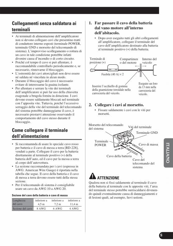
EN
GLIS
HES
PA
ÑO
LD
EU
TS
CH
FR
AN
ÇA
ISIT
ALIA
NO
NED
ERLA
ND
Sê
ìë
ëä
àâ
8
Collegamenti senza saldatura aiterminali• Ai terminali di alimentazione dell’amplificatore
non si devono collegare cavi che presentino trattidi conduttore interno esposti (terminale POWER,terminale GND e morsetto del telecomando disistema). L’improvviso scollegamento o rottura diun cavo in tale condizione potrebbe infattidivenire causa d’incendio o di corto circuito.
• Poiché col tempo il cavo si può allentare, èraccomandabile controllarlo periodicamente e, senecessario, rinnovarne il bloccaggio.
• L’estremità dei cavi attorcigliati non deve esserené saldata né vincolata in alcun modo.
• Durante il bloccaggio del cavo è necessarioevitare di interessarne la guaina isolante.
• Per allentare e serrare la vite dei terminalidell’amplificatore si può far uso della chiavettaesagonale a brugola fornita in dotazione. I cavidevono essere saldamente bloccati nel terminalecon l’apposita vite. Tuttavia, poiché l’eccessivoserraggio della vite del terminale del telecomandodel sistema potrebbe danneggiarne il cavo, ènecessario prestarvi attenzione osservando ilcomportamento del cavo stesso durante ilbloccaggio.
Come collegare il terminale dell’alimentazione• Si raccomamnda di usare lo speciale cavo rosso
per batteria e il cavo di messa a terra [RD-228],venduti a parte. Collegare il cavo per la batteriadirettamente al terminale positivo (+) dellabatteria dell’auto, ed il cavo per la messa a terraal corpo dell’autovettura.
• La sezione raccomandata per i cavi (espressa inAWG: American Wire Gauge) è riportata nellatabella che segue. Il cavo della batteria e il cavodi messa a terra devono essere tutti della stessasezione.
• Per il telecomando di sistema è consigliabileusare un cavo da AWG 10 a AWG 20.
Sezione del cavo della batteria e cavo di massa
Lunghezza inferiore a inferiore a inferiore adel cavo 4,5 m 7,2 m 11,4 m
Sezione del cavo 8 AWG 6 AWG 4 AWG
1. Far passare il cavo della batteriadal vano motore all’interno dell’abitacolo.• Dopo aver eseguito tutti gli altri collegamenti
all’amplificatore, collegare il terminale delcavo dell’amplificatore destinato alla batteriaal terminale positivo (+) della batteria.
2. Collegare i cavi al morsetto.• Fissare saldamente i cavi con le viti per
morsetti.
ATTENZIONEQualora non si fissi saldamente al terminale il cavodella batteria al terminale con le apposite viti, l’areadel terminale stesso potrebbe surriscaldarsi divenen-do quindi eventualmente causa di danneggiamenti edi lesioni quali, ad esempio, lievi ustioni.
Compartimeno del motore
Interno del veicolo
Eseguire un foroda 13 mm nellacarrozzeria delveicolo.
Inserire l’occhiello di gommadella guarnizione toroidale nellacarrozzeria del veicolo.
Terminale diposizione (+)
Fusibile (40 A) × 2
Cavo della batteria
TerminalePOWER Cavo di massa
Terminale GND
Morsetto del telecomandodel sistema
Cavo del telecomando delsistema
Viti del terminale

9
Come collegare l’unità
Come collegare il terminale diuscita degli altoparlanti• Per l’altoparlante è consigliabile usare un cavo da
AWG 10 a AWG 16.
1. Con delle pinzette o un taglierinorimuovere all’estremità dei cavid’altoparlante circa 10 mm a 12 mm di guaina isolante.
2. Collegare i cavi degli altoparlanti alterminale di uscita degli altoparlanti.• Fissare saldamente i cavi con le viti per
morsetti.
Utilizzo dell’ingresso altoparlantiCon i cavetti d’ingresso altoparlantiprovvisti di spina RCA, forniti indotazione, collegare all’amplificatore icavetti dell’uscita altoparlantidell’apparecchio stereo dell’auto.• Fare scorrere il selettore a sinistra (SP).
7 Connessioni in caso di utilizzodell’ingresso altoparlanti.
Collegamento dei cavi d’altopar-lanti
Collegare i fili dell’altoparlante in basealle seguenti illustrazioni.
per circa 10 mm a 12 mm
Subwoofer
Viti del terminale
Terminaledi uscita deglialtoparlanti Cavo di
altoparlante
Uscitaaltoparlanti
Cavetto d’ingressoaltoparlantiprovvisto di spinaRCA
Al presa d’ingresso tipoRCA di questa unità.
Apparecchio stereo dell’auto
Bianco: Nero: Nero: Rosso:Sinistra + Sinistra ≠ Destra ≠ Destra +

EN
GLIS
HES
PA
ÑO
LD
EU
TS
CH
FR
AN
ÇA
ISIT
ALIA
NO
NED
ERLA
ND
Sê
ìë
ëä
àâ
10
PRECAUZIONE• Non installare l’unità sulle posizioni seguenti:
—Posti dove potrebbe ferire il conducente o ipassaggeri se il veicolo si arrestabruscamente.
—Posti dove potrebbe disturbare il conducente,come pavimento verso la parte anteriore delsedile del conducente.
• Assicurarsi che i cavi non vengano presi nel meccanismo a scorrimento del sedile, provocandocosì un cortocircuito.
• Verificare che nulla si trovi dietro il pannelloquando si esegue un foro per l’installazionedell’amplificatore. Assicurarsi di proteggere tuttii cavi e componenti importanti come linee delcarburante, linee del freno e cablaggio elettrico,contro i danni.
• Installare le viti autofilettanti in tale modo che lepunte delle viti non siano in contatto con i cavi.Questa precauzione è importante per evitare che icavi vengano tagliati dalle vibrazioni dellavettura, poiché cio può risultare in un incendio.
• NON lasciare che l’amplificatore entri in contattocon liquidi nel luogo in cui esso è installato. Sipotrebbero generare infatti scosse elettriche. Ilcontatto con i liquidi può altresì danneggiarel’amplificatore stesso e i diffusori, con emissionedi fumo e creazione di surriscaldamento. Lasuperficie dell’amplificatore o quella deglialtoparlanti ad esso collegati potrebbe inoltredivenire molto calda e, al contatto, procurare piccole scottature.
• Per ottenere una installazione appropriata,utilizzare le parti fornite nel modo specificato. Sequalunque parte diversa da quelle fornite vieneutilizzata, potrà danneggiare le parti internedell’amplificatore, oppure potrà allentarsi el’amplificatore rischia di danneggiarsi.
• Non sostituire mai il fusibile con uno di valore otaratura superiore a quella del fusibile originale.L’uso di fusibili non adeguati può determinare unsurriscaldamento o generare fumo, eventualmentedanneggiando il prodotto e procurando lesioni oustioni.
PRECAUZIONE:Per evitare malfunzionamenti e/o lesioni• Per assicurare una dissipazione appropriata di
calore dall’amplificatore, fare attenzione aiseguenti punti per l’installazione.
—Lasciare uno spazio adeguato sopral’amplificatore per ottenere una ventilazioneappropriata.
—Non ricoprire l’amplificatore con tappeti omoquette.
• NON lasciare che l’amplificatore entri in contattocon liquidi nel luogo in cui esso è installato. Si potrebbero generare infatti scosse elettriche. Il contatto con i liquidi può altresì danneggiarel’amplificatore stesso e i diffusori, con emissionedi fumo e creazione di surriscaldamento. Lasuperficie dell’amplificatore o quella deglialtoparlanti ad esso collegati potrebbe inoltredivenire molto calda e, al contatto, procurare piccole scottature.
• Non installare l’amplificatore in luoghi instabilicome il pannello della ruota di scorta.
• La posizione ottimale d’installazione varia aseconda del tipo di veicolo. L’amplificatore devecomunque essere installato in zone del veicoloadeguatamente rigide.
• Eseguire prima i collegamenti provvisori, poiverificare se l’amplificatore ed il sistemafunzionano in modo adeguato.
• Una volta installato l’amplificatore si raccomandadi verificare che la ruota di scorta, il martinetto disollevamento e i necessari attrezzi sianofacilmente estraibili dal veicolo.
Installazione

11
Installazione
Fissaggio del telecomando dipotenziamento dei bassiDeve essere fissato con viti autofilettanti (3 mm ×10 mm) in un punto del veicolo facilmente accessi-bile, ad esempio sotto il cruscotto.
Esempio dell’installazione sulpavimento oppure sullo chassis
1. Posizionare l’amplificatore dovedeve essere installato. Inserire le vitiautofilettanti fornite (4 mm ×18 mm) nei fori delle viti. Spingerele viti con un cacciavite per fare deisegni dove i fori dell’installazionedevono essere fatti.
2. Eseguire dei fori del diametro di 2,5 mm al punto marcato edinstallare l’amplificatore, sia sutappeto, sia direttamente sullochassis.
Vite autofilettante (3 mm × 10 mm)
Eseguire dei fori deldiametro di 2,5 mm
Vite autofilettante(4 mm × 30 mm)
Pavimentooppurechassis

EN
GLIS
HES
PA
ÑO
LD
EU
TS
CH
FR
AN
ÇA
ISIT
ALIA
NO
NED
ERLA
ND
Sê
ìë
ëä
àâ
12
Alimentazione ................................................................................................... 14,4 V CC (10,8 V a 15,1 V permissìbili)Collegamento a terra .................................................................................................................................. Tipo negativoeConsumo ............................................................................................................. 27,0 A (ad alimentazione continua, 4 Ω)Corrente media consumata* .................................................................................................... 7,5 A (4 Ω per una canale)
15,0 A (2 Ω per una canale)Fusibile ................................................................................................................................................................... 30 A × 2Dimensioni .......................................................................................................... 290 mm (L) × 56 mm (A) × 200 mm (P)
(terminali esclusi)Peso ................................................................................................................ 3,2 kg (Cavi per il cablaggio non compresi)Uscita massima di potenza ....................................................................................... 600 W × 1 (4 Ω) / 1 200 W × 1 (2 Ω)Potenza continua (14,4 V) ............................................................... 4 Ω, da 20 Hz a 240 Hz, 1,0 % THD, 300 W × 1
2 Ω, 50 Hz, 1,0 % THD, 600 W × 1Impedenza di carico ............................................................................................................... 4 Ω (2 Ω a 8 Ω permissìbili)Risposta in frequenza ........................................................................................................ 10 Hz a 240 Hz (+0 dB, –3 dB)Rapporto segnale/rumore ................................................................................................................... 80 dB (IEC-A rete) Distorsione ........................................................................................................................................ 0,3 % (10 W, 100 Hz)Filtro passa-basso ...................................................................................................... Frequenza di taglio: 40 Hz a 240 Hz
Pendenza di taglio: –12 dB/ottavaPotenziamento dei bassi .......................................................................................................................... Frequenza: 50 Hz
Livello: 0 dB a 12 dBComando del guadagno ................................................................................................................... RCA: 200 mV a 6,5 V
Altoparlante: 0,8V a 26 VLivello di ingresso massimo / impedenza ........................................................................................... RCA: 6,5 V / 22 kΩ
Altoparlante: 26 V / 90 kΩ
Nota:• Caratteristiche tecniche e design soggetti a modifiche senza preavviso a causa di migliorie.
*Corrente media consumata • La corrente media consumata è circa uguale alla corrente massima consumata da
questa unità quando un segnale audio viene immesso. Tenere presente questo valore per il calcolo della corrente totale consumata dai vari amplificatori utilizzati.
Caratteristiche

1
Alvorens gebruik ........................................ 1Bezoek onze website ........................................ 2Bij problemen .................................................... 2Over dit product ................................................ 2WAARSCHUWING ........................................ 2WAARSCHUWING ........................................ 2
Instellen van dit toestel ............................ 3Versterkingsregelaar .......................................... 3Regelaar voor LPF (lage-doorlaatfilter)
drempelfrequentie ...................................... 4Spanningsindicator (Blauw) .............................. 4Schakelaar voor de regeling van de
slagfrequentie (BFC) .................................. 4Ingangsschakelaar ............................................ 4Bass Boost regelaar .......................................... 4Correct instellen van de Gain
(extra versterking) ...................................... 5
Aansluiten van het toestel ...................... 6Aansluitschema ................................................ 7Aansluitingen zonder solderen .......................... 8Aansluiten van het spanningsaansluitpunt ........ 8Verbinden van de
luidsprekeruitgangsaansluitingen .............. 9Gebruik van de luidspreker-ingang .................. 9Aansluiten van de luidsprekerdraden ................ 9
Installatie .................................................. 10Bevestigen van de Bass Boost
afstandsbediening .................................... 11Voorbeeld van installatie op de vloermat of
op het chassis ............................................ 11
Technische gegevens ............................ 12
Dank U zeer voor de aanschaf van ditPIONEER-product. Lees deze gebruiks-aanwijzing goed door, voordat het toestelin gebruik genomen wordt.
In de lidstaten van de EU, Zwitserland enNoorwegen kunnen particulieren hungebruikte elektronische producten gratisbij de daarvoor bestemde verzamelplaatsenof een verkooppunt (indien u aldaar eengelijkwaardig nieuw product koopt)inleveren.Indien u zich in een ander danbovengenoemd land bevindt kunt u contactopnemen met de plaatselijke overheid voorinformatie over de juiste verwijdering vanhet product.Zodoende zorgt u ervoor dat hetverwijderde product op de juiste wijzewordt behandeld, opnieuw bruikbaar wordtgemaakt, t gerecycleerd en het nietschadelijk is voor de gezondheid en hetmilieu.
Bezoek onze websiteHier vindt u onze site:http://www.pioneer.nl• Registreer uw product. Wij bewaren de
gegevens van het product dat u heeftaangeschaft zodat u deze eenvoudigkunt opvragen als u die nodig mochthebben voor de verzekering na bijvoorbeeld verlies of diefstal.
• Op onze website vindt u de laatste informatie over Pioneer Corporation.
Deponeer dit product niet bijhet gewone huishoudelijkafval wanneer u het wiltverwijderen. Er bestaat eenspeciaal wettelijkvoorgeschrevenverzamelsysteem voor dejuiste behandeling, hetopnieuw bruikbaar maken ende recycling van gebruikteelektronische producten.
Inhoudsopgave Alvorens gebruik
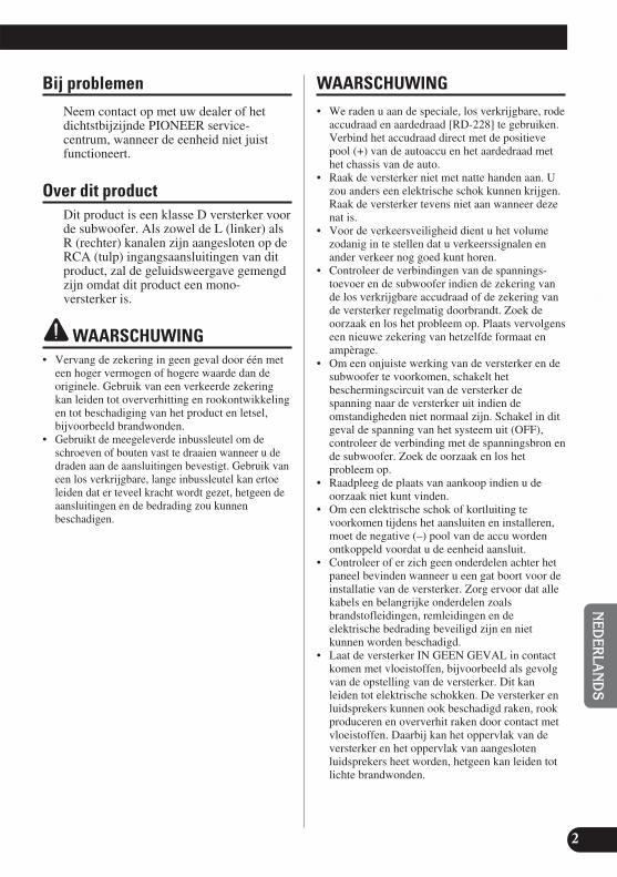
EN
GLIS
HES
PA
ÑO
LD
EU
TS
CH
FR
AN
ÇA
ISIT
ALIA
NO
NED
ERLA
ND
Sê
ìë
ëä
àâ
2
Bij problemenNeem contact op met uw dealer of hetdichtstbijzijnde PIONEER service-centrum, wanneer de eenheid niet juistfunctioneert.
Over dit productDit product is een klasse D versterker voorde subwoofer. Als zowel de L (linker) alsR (rechter) kanalen zijn aangesloten op deRCA (tulp) ingangsaansluitingen van ditproduct, zal de geluidsweergave gemengdzijn omdat dit product een mono-versterker is.
WAARSCHUWING• Vervang de zekering in geen geval door één met
een hoger vermogen of hogere waarde dan deoriginele. Gebruik van een verkeerde zekeringkan leiden tot oververhitting en rookontwikkelingen tot beschadiging van het product en letsel,bijvoorbeeld brandwonden.
• Gebruikt de meegeleverde inbussleutel om deschroeven of bouten vast te draaien wanneer u dedraden aan de aansluitingen bevestigt. Gebruik vaneen los verkrijgbare, lange inbussleutel kan ertoeleiden dat er teveel kracht wordt gezet, hetgeen deaansluitingen en de bedrading zou kunnenbeschadigen.
WAARSCHUWING• We raden u aan de speciale, los verkrijgbare, rode
accudraad en aardedraad [RD-228] te gebruiken.Verbind het accudraad direct met de positievepool (+) van de autoaccu en het aardedraad methet chassis van de auto.
• Raak de versterker niet met natte handen aan. Uzou anders een elektrische schok kunnen krijgen.Raak de versterker tevens niet aan wanneer dezenat is.
• Voor de verkeersveiligheid dient u het volumezodanig in te stellen dat u verkeerssignalen enander verkeer nog goed kunt horen.
• Controleer de verbindingen van de spannings-toevoer en de subwoofer indien de zekering vande los verkrijgbare accudraad of de zekering vande versterker regelmatig doorbrandt. Zoek deoorzaak en los het probleem op. Plaats vervolgenseen nieuwe zekering van hetzelfde formaat enampèrage.
• Om een onjuiste werking van de versterker en desubwoofer te voorkomen, schakelt hetbeschermingscircuit van de versterker despanning naar de versterker uit indien deomstandigheden niet normaal zijn. Schakel in ditgeval de spanning van het systeem uit (OFF),controleer de verbinding met de spanningsbron ende subwoofer. Zoek de oorzaak en los hetprobleem op.
• Raadpleeg de plaats van aankoop indien u deoorzaak niet kunt vinden.
• Om een elektrische schok of kortluiting tevoorkomen tijdens het aansluiten en installeren,moet de negative (–) pool van de accu wordenontkoppeld voordat u de eenheid aansluit.
• Controleer of er zich geen onderdelen achter hetpaneel bevinden wanneer u een gat boort voor deinstallatie van de versterker. Zorg ervoor dat allekabels en belangrijke onderdelen zoalsbrandstofleidingen, remleidingen en deelektrische bedrading beveiligd zijn en nietkunnen worden beschadigd.
• Laat de versterker IN GEEN GEVAL in contactkomen met vloeistoffen, bijvoorbeeld als gevolgvan de opstelling van de versterker. Dit kanleiden tot elektrische schokken. De versterker enluidsprekers kunnen ook beschadigd raken, rookproduceren en oververhit raken door contact metvloeistoffen. Daarbij kan het oppervlak van deversterker en het oppervlak van aangeslotenluidsprekers heet worden, hetgeen kan leiden totlichte brandwonden.

3
Instellen van dit toestel
VersterkingsregelaarDraai de versterkingsregelaar naar rechts indien de weergave te zacht klinkt,zelf wanneer het volume is verhoogd met de auto-stereo die u met dezeeindversterker gebruikt. Draai de versterkingsregelaar naar links indien hetgeluid vervormt wanneer het volume wordt verhoogd.• Wanneer u een auto-stereo gebruikt met RCA (standaard uitgangsspanning 500 mV),
dient u de NORMAL stand in te stellen. Wanneer u een Pioneer auto-stereo met RCAgebruikt, met een maximale uitgangsspanning van 4 V of meer, dient u het niveau aante passen aan het uitgangsniveau van de auto-stereo.

EN
GLIS
HES
PA
ÑO
LD
EU
TS
CH
FR
AN
ÇA
ISIT
ALIA
NO
NED
ERLA
ND
Sê
ìë
ëä
àâ
4
Schakelaar voor de regeling van de slagfrequentie (BFC)Als u een slag of dreun hoort bij het luisteren naar een MW/LW (MG/LG)-uitzending op uwautostereo, kunt u de stand van de BFC-schakelaar wijzigen met een kleine schroevedraaiermet platte kop.
Regelaar voor LPF (lage-doorlaatfilter) drempelfrequentieU kunt een drempelfrequentie van 40 Hz t/m 240 Hz kiezen.
Bass Boost regelaarU kunt de extra versterking van de lage tonen (Bass Boost) regelen van 0 dB t/m 12 dB.Voor aanwijzingen omtrent het aansluiten van de Bass Boost afstandsbediening op deversterker, verwijzen we u naar het “Aansluitschema”.
Spanningsindicator (Blauw)De spanningsindicator licht op wanneer de spanning wordt ingeschakeld.
IngangsschakelaarHet is mogelijk signalen te ontvangen van de externe uitgang van een autostereo of de luidspreker-uitgang van een autostereo. Verzet de ingangsschakelaar voor u de stroom inschakelt. Omdat ereen zeer hard geluid geproduceerd kan worden via de luidsprekers wanneer u de ingangsschakelaaromzet terwijl de stroom is ingeschakeld, zal de stroom worden uitgeschakeld door een ingebouwdebeveiliging. Bij gebruik van een externe uitgang dient u deze schakelaar naar rechts (RCA) tezetten. Voor instructies betreffende de aansluitingen verwijzen we u naar het “Aansluitschema”.Bij gebruik van een luidspreker-uitgang dient u de schakelaar naar links (SP) te zetten. In dit gevalis het nodig het meegeleverde luidspreker-ingangssnoer met RCA (tulp) stekkers te gebruiken. Zievoor details de paragraaf “Gebruik van de luidspreker-ingang”.

5
Instellen van dit toestel
Correct instellen van de Gain(extra versterking)• Dit toestel is uitgerust met een beveiliging die
bedoeld is om storingen aan het toestel zelf en aande luidsprekers veroorzaakt door een te hoog uitgangsvermogen, onjuist gebruik of onjuisteaansluitingen te voorkomen.
• Wanneer er geluid wordt gereproduceerd bij eente hoog volume enz. zal deze functie de geluidsweergave binnen een paar seconden onderbreken. Dit duidt echter niet op een storing.Wanneer u het volume van het hoofdtoestel lagerzet, zal de geluidsweergave worden hersteld.
• Als de geluidsweergave wordt onderbroken, is hetmogelijk dat de ‘gain’ (extra versterking) van dittoestel incorrect is ingesteld. Om er zeker van tekunnen zijn dat de geluidsweergave niet zal worden onderbroken wanneer het hoofdtoestelmet een hoog volume weergeeft, dient u de ‘gain’instelling van de versterker op een geschikte standte zetten in overeenstemming met het maximalepre-out uitgangsniveau van het hoofdtoestel.
‘Gain’ instelling van dit toestel
• Op de afbeelding hierboven is de GAIN ingesteldop NORMAL.
Zo is het niet nodig het volume van hethoofdtoestel te verlagen en wordt een te hooguitgangsniveau voorkomen.
Verhouding tussen de ‘gain’ van de versterker en het uitgangsvermogen vanhet hoofdtoestel
• Als u de ‘gain’ (extra versterking) van de versterker op een ongeschikt niveau instelt, zalalleen de vervorming toenemen en zal het vermogen slechts marginaal toenemen.
Golfvorm signaal bij weergave met hoogvolume via de ‘gain’ instelling van de versterker
• Bij een hoog uitgangsvermogen wordt degolfvorm van het signaal vervormd, terwijl hetvermogen slechts marginaal zal veranderen als ude ‘gain’ van de versterker hoger instelt.
• Als u het volume van het hoofdtoestel hoger zeten de ‘gain’ (extra versterking) van de versterkerop de juiste stand, maar merkt dat het geluid nogsteeds zo nu en dan onderbroken wordt, dan dientu contact op te nemen met uw dichtstbijzijndeerkende PIONEER service-centrum.
Gelijk vermogen
‘Gain’ versterker(normaal)
‘Gain’ versterker(maximaal)
Golfvormsignaal
Golfvormsignaal
Normale ‘gain’ Maximale ‘gain’
‘Gain’ versterker(normaal)
‘Gain’ versterker(maximaal)
Volumestappen hoofdtoestel
Vermogen
Normale ‘gain’
Vermogen
Volumestappen hoofdtoestel
Maximale ‘gain’
Gelijk vermogen
Pre-out niveau: 2 V(Standaard: 500 mV)
Pre-out niveau: 4 V
Pre-out niveau: 6,5 V

Aansluiten van het toestel
6
EN
GLIS
HES
PA
ÑO
LD
EU
TS
CH
FR
AN
ÇA
ISIT
ALIA
NO
NED
ERLA
ND
Sê
ìë
ëä
àâ
WAARSCHUWING• Voorkom kortsluiting en beschadiging van de
eenheid en ontkoppel de nagatieve (–) accupoolvan het voertuig.
• Zet de bedrading met kabelklemmen of isoleer-of plakband vast. Bescherm de bedrading door degedeelten in de buurt van metalen delen metisoleerband af ze dekken.
• Leid de draden niet langs plaatsen die heetworden, bijvoorbeeld in de buurt van deverwarmingselementen. Indien de isolatie vandraden heet wordt, zullen de draden wordenbeschadigd met kortsluiting tot gevolg.
• Zorg dat de bedrading de werking van bewegendeof verplaatsbare onderdelen, bijvoorbeeld deversnelling, handrem of stoelverstelmechanismenvan het de auto niet hindert.
• Sluit draden niet kort. Het beschermingscircuitwerkt anders namelijk niet wanneer het voor deveiligheid zou moeten functioneren.
• Tap het spanningsdraad van dit toestel niet afvoor gebruik van andere apparaten. Hetvermogen van het draad zou dan namelijk wordenoverschreden, met oververhitting tot gevolg.
• Vervang de zekering in geen geval door één meteen hoger vermogen of hogere waarde dan deoriginele. Gebruik van een verkeerde zekeringkan leiden tot oververhitting en rookontwikkelingen tot beschadiging van het product en letsel,bijvoorbeeld brandwonden.
WAARSCHUWING:Om beschadiging en/of letsel tevoorkomen• Aard het luidsprekersnoer niet rechtstreeks en
sluit evenmin een negatief snoer (–) aan voorverschillende luidsprekers.
• Dit toestel is ontworpen voor auto’s met een accuvan 12 V en negatieve aarding. Kijk bijgevolgeerst de accuspanning na voor u het toestelinstalleert in een recreatief voertuig, vrachtwagenof bus.
• De accu raakt mogelijk uitgeput indien de auto-stereo langdurig is ingeschakeld maar de motorstationair draait of is uitgeschakeld. Zet de auto-stereo uit wanneer de motor stationair draait of isuitgeschakeld.
• Als het systeem-afstandbedieningssnoer van deversterker is aangesloten op despanningsaansluiting via de contactschakelaar(12 V gelijkstroom), is de versterker altijdingeschakeld wanneer het contact aanstaat,ongeacht of de auto-stereo wel of niet door u isaangezet. Hierdoor raakt de accu mogelijkuitgeput wanneer de motor stationair draait of isuitgeschakeld.
• Sluit GEEN subwoofer aan met een lagereimpedantie dan opgegeven onder “Aansluiten vande luidsprekerdraden”. Dit kan namelijk leidentot schade aan de versterker, rookontwikkeling en oververhitting. Ook kan het oppervlak van de versterker heet aanvoelen, hetgeen zelfs kan leiden tot lichte brandwonden.
• U kunt twee soorten subwoofers aansluiten op deversterker; 1: een subwoofer met een nominaalingangsvermogen van 350 W of meer en eenimpedantie van 4 Ω, of 2: een subwoofer met eennominaal ingangsvermogen van 600 W of meeren een impedantie van 2 Ω. Als het nominaleingangsvermogen en de impedantie buiten degenoemde waarden ligt, kan de subwoofer vlamvatten, rook uitstoten of kapot gaan.
• Plaats en leid het los verkrijgbare accudraad zover als mogelijk uit de buurt van deluidsprekerdraden. Plaats en leid het losverkrijgbare accudraad en aardedraad,luidsprekerdraden en de versterker zo ver alsmogelijk uit de buurt van de antenne,antennekabel en tuner.
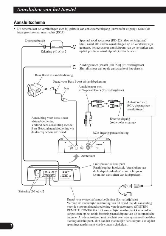
7
Aansluiten van het toestel
Aansluitschema • Dit schema laat de verbindingen zien bij gebruik van een externe uitgang (subwoofer uitgang). Schuif de
ingangsschakelaar naar rechts (RCA).
6 m
Doorvoerbuisje Speciaal rood accusnoer [RD-228] (los verkrijgbaar)Sluit, nadat alle andere aansluitingen op de versterker zijngemaakt, het accusnoer-aansluitpunt van de versterker aanop het positieve aansluitpunt (+) van de accu.
Aardingssnoer (zwart) [RD-228] (los verkrijgbaar)Sluit dit snoer aan op de carrosserie of het chassis.
Zekering (30 A) × 2
Autostereo metRCA-uitgangspen-aansluitingen
Externe uitgang(subwoofer uitgang)
Aansluitsnoer met RCA-penstekkers (los verkrijgbaar).
RCA-ingangspenaansluiting
Draad voor systeemafstandsbediening (los verkrijgbaar)Verbind de mannelijke aansluiting van dit draad met de aansluitingvoor de systeemafstandsbediening van de autostereo (SYSTEMREMOTE CONTROL). Het vrouwelijke aansluitpunt kan wordenaangesloten op het relais-besturingsaansluitpunt van de automatischeantenne. Als de autostereo niet beschikt over een systeem-afstandsbe-dieningsaansluitpunt, sluit dan het mannelijke aansluitpunt aan op hetspanningsaansluitpunt via de contactschakelaar.
Luidspreker-aansluitpuntRaadpleeg het hoofdstuk “Aansluiten vande luidsprekerdraden” voor richtlijneni.v.m. het aansluiten van luidsprekers.
Aansluiting voor Bass BoostafstandsbedieningVerbind deze aansluiting met deBass Boost afstandsbediening viade daarbij behorende draad.
Bass Boost afstandsbediening
Draad voor Bass Boost afstandsbediening
Zekering (40 A) × 2
Achterkant

EN
GLIS
HES
PA
ÑO
LD
EU
TS
CH
FR
AN
ÇA
ISIT
ALIA
NO
NED
ERLA
ND
Sê
ìë
ëä
àâ
8
Aansluitingen zonder solderen• Sluit geen bedrading met blootliggende
geleiderkern aan op de stroomaansluitingen vandeze versterker (spanningsaansluitpunt, GNDaardeaansluiting, aansluiting voorsysteemafstandsbediening). Als de blootliggendegeleiderkern van een dergelijke draad los raakt ofbreekt, zou dit kunnen leiden tot kortsluiting ofbrand.
• Omdat de draad na verloop van tijd los zal komente zitten, moet u deze regelmatig controleren enindien nodig opnieuw vastzetten.
• Zet de uiteinden van de draadjes niet vast door zete solderen of af te binden.
• Let er bij het vastdraaien op dat u de draad nietmet de isolatie vastklemt.
• Gebruik de meegeleverde inbussleutel om deschroef van de versterkeraansluiting vast of los tedraaien. Zet de draad goed vast met de schroefvan de aansluiting. Omdat echter te vastaandraaien van de aansluitingsschroef voor de systeemafstandsbediening het risico met zich meebrengt dat de draad beschadigd raakt, moet ude draad bij het vastdraaien goed in de gatenhouden en voorzichtig zijn dat u de schroef niet tevast aandraait.
Aansluiten van hetspanningsaansluitpunt• We raden u aan de speciale, los verkrijgbare, rode
accudraad en aardedraad [RD-228] te gebruiken.Verbind het accudraad direct met de positievepool (+) van de autoaccu en het aardedraad methet chassis van de auto.
• De aanbevolen maten voor de draden (AWG:American Wire Gauge) zijn als volgt. De accudraad en de aarddraad moeten allemaaldezelfde maat hebben.
• Gebruik draad van 10 AWG tot 20 AWG voor dedraad voor de systeemafstandsbediening.
Maat voor de accudraad en de aarddraad
Draadlengte minder dan minder dan minder dan4,5 m 7,2 m 11,4 m
Draadmaat 8 AWG 6 AWG 4 AWG
1. Trek het accudraad van hetmotorgedeelte naar de cabine vande auto.• Sluit, nadat alle andere aansluitingen op de
versterker zijn gemaakt, het accusnoer-aansluitpunt van de versterker aan op hetpositieve aansluitpunt (+) van de accu.
2. Sluit de draden aan.• Zet de draden stevig met de schroeven van de
aansluitingen vast.
WAARSCHUWINGAls de accudraad niet goed wordt bevestigd aan hetaansluitpunt met behulp van de schroef, kan hetaansluitpunt oververhit raken, hetgeen kan leiden totschade en letsel, met inbegrip van lichtebrandwonden.
Motor-compartiment
Interieur vanhet voertuig
Boor een gatvan 13 mm inde carrosserievan de auto.
Steek het rubberen O-vormigedoorvoerbuisje in de carrosserievan de auto.
Positieveaansluiting (+)
Zekering (40 A) × 2
GND aarde-aansluiting
Spannings-aansluitpunt (POWER)
Accudraad
Aansluiting voor systeemafstandsbediening
Draad voor systeemafstands-bediening
Aardingssnoer
Aansluitpuntschroeven

9
Aansluiten van het toestel
Verbinden van de luidsprekeruitgangsaansluitingen• Gebruik draad van 10 AWG tot 16 AWG voor
luidsprekerdraad.
1. Strip ongeveer 10 mm tot 12 mmvan de isolatie van het uiteinde vande luidsprekerdraden met eenstriptang of mes.
2. Verbind de luidsprekerdraden metde luidsprekeruitgangsaansluiting.• Zet de luidsprekerdraden goed met de
schroeven van de aansluiting vast.
Gebruik van de luidspreker-ingangSluit de uitgangsdraden van de autostereoaan op de versterker via de meegeleverdeluidspreker-ingangsdraad met RCA (tulp)stekkers.• Schuif de ingangsschakelaar naar links (SP).
7 Verbindingen bij gebruik van de luidspreker-ingang
Aansluiten van deluidsprekerdraden
Sluit de luidsprekersnoeren aan zoalsaangegeven in de onderstaandeafbeeldingen.
10 mm tot 12 mm
Subwoofer
Aansluitpuntschroeven
Luidspreker-uitgangsaansluiting Luidsprekerdraad
Luidspreker-ingang
Luidspreker-ingangsdraad metRCA (tulp) stakkers
Naar de RCA-ingangsaansluitingvan dit toestel.
Autostereo
Wit: Zwart: Zwart: Rood:Links + Links ≠ Rechts ≠ Rechts +

EN
GLIS
HES
PA
ÑO
LD
EU
TS
CH
FR
AN
ÇA
ISIT
ALIA
NO
NED
ERLA
ND
Sê
ìë
ëä
àâ
10
WAARSCHUWING• Niet installeren op:
—Plaatsen waar het de bestuurder of passagierszou kunnen verwonden wanner de autoplotseling stopt.
—Plaasten waar de bestuurder door de eenheidtijdens het rijden zou kunnen wordengehinderd, zoals bijvoorbeeld op de vloervoor de bestuurdersstoel.
• Kontroleer dat draden niet in de weg van destoelverstelmechanismen zitten. Dit zou namelijkkortsluiting kunnen veroorzaken.
• Controleer of er zich geen onderdelen achter hetpaneel bevinden wanneer u een gat boort voor deinstallatie van de versterker. Zorg ervoor dat allekabels en belangrijke onderdelen zoalsbrandstofleidingen, remleidingen en deelektrische bedrading beveiligd zijn en nietkunnen worden beschadigd.
• Plaats tapse schroeven zodanig dat de kop van deschroef niet in aanraking met draden komt. Dit isbelangrijk en voorkomt dat draden door trillingenvan het voertuig door worden gesneden metbrand tot gevolg.
• Laat de versterker IN GEEN GEVAL in contactkomen met vloeistoffen, bijvoorbeeld als gevolgvan de opstelling van de versterker. Dit kanleiden tot elektrische schokken. De versterker enluidsprekers kunnen ook beschadigd raken, rookproduceren en oververhit raken door contact metvloeistoffen. Daarbij kan het oppervlak van deversterker en het oppervlak van aangeslotenluidsprekers heet worden, hetgeen kan leiden totlichte brandwonden.
• Gebruik de bijgeleverde onderdelen op de manierdie is beschreven om de installatie uit te voerenzoals het hoort. Als andere onderdelen dandiegene die zijn bijgeleverd worden gebruikt, ishet mogelijk dat inwendige onderdelen van deversterker schade oplopen of loskomen, zodat deversterker niet meer werkt.
• Vervang de zekering in geen geval door één meteen hoger vermogen of hogere waarde dan deoriginele. Gebruik van een verkeerde zekeringkan leiden tot oververhitting en rookontwikkelingen tot beschadiging van het product en letsel,bijvoorbeeld brandwonden.
WAARSCHUWING:Om slechte werking en/of letsel tevoorkomen• Zorg dat de ventiltie van de versterker niet wordt
gehinderd, en let derhalve op de volgende puntentijdens het installeren.
—Zorg dat er voor een goede vrije ruimteboven de versterker is.
—Bedek de versterker niet met een vloermat ofkleed.
• Laat de versterker IN GEEN GEVAL in contactkomen met vloeistoffen, bijvoorbeeld als gevolgvan de opstelling van de versterker. Dit kanleiden tot elektrische schokken. De versterker enluidsprekers kunnen ook beschadigd raken, rookproduceren en oververhit raken door contact metvloeistoffen. Daarbij kan het oppervlak van deversterker en het oppervlak van aangeslotenluidsprekers heet worden, hetgeen kan leiden totlichte brandwonden.
• Installeer de versterker niet op onstabieleplaatsen, zoals op de reservebandhouder.
• De beste installatieplaats is verschillendafhankelijk van het automerk en model en uwwensen. Plaats de versterker echter beslist stevigop een stabiele plaats.
• Maak eerst voorlopige aansluitingen en ga na ofde versterker en het systeem naar behorenwerken.
• Na het installeren van de versterker, moet ucontroleren dat het reservewiel, de krik en hetgereedschap nog gemakkelijk kunnen wordenverwij-derd.
Installatie

11
Installatie
Bevestigen van de Bass Boost afstandsbedieningBevestig deze met zelftappende schroeven (3 mm ×10 mm) op een gemakkelijk toegankelijke plek,bijvoorbeeld onder het dashboard.
Voorbeeld van installatie op devloermat of op het chassis
1. Zet de versterker op de plaats waarhij moet worden geïnstalleerd. Steekde bijgeleverde tapschroeven (4 mm × 18 mm) in de schroefgaten.Druk met een schroevendraaier opde schroeven zodat ze een inkepingmaken op de plaats waar de gatenvoor de installatie moeten komen.
2. Boor gaten met een diameter van2,5 mm op de plaatsen die zijngemerkt en installeer de versterker,ofwel op de vloermat ofwelrechtstreeks op het chassis.
Zelftappende schroef (3 mm × 10 mm)
Boor een gat met een diametervan 2,5 mm
Tapschroef(4 mm × 30 mm)
Vloermatof chassis

EN
GLIS
HES
PA
ÑO
LD
EU
TS
CH
FR
AN
ÇA
ISIT
ALIA
NO
NED
ERLA
ND
Sê
ìë
ëä
àâ
12
Spanningsbron .................................................................................. 14,4 V gelijkstroom (10,8 V t/m 15,1 V toelaatbaar)Aarding ...................................................................................................................................... Negatieve klem aan massaStroomverbruik .......................................................................................................... 27,0 A (met continu spanning, 4 Ω)Gemiddeld stroomverbruik* .................................................................................................. 7,5 A (4 Ω voor een kanaal)
15,0 A (2 Ω voor een kanaal)Zekering .................................................................................................................................................................. 30 A × 2Afmetingen ........................................................................................................ 290 mm (B) × 56 mm (H) × 200 mm (D)
(Exclusief aansluitingen)Gewicht ........................................................................................................................................ 3,2 kg (Excl. bedrading)Maximale spanningsuitvoer ......................................................................................600 W × 1 (4 Ω) / 1 200 W × 1 (2 Ω)Continu vermogen (14,4 V) ............................................................… 4 Ω, 20 Hz t/m 240 Hz, 1,0 % THV, 300 W × 1
2 Ω, 50 Hz, 1,0 % THV, 600 W × 1Aansluitimpedantie .............................................................................................................. 4 Ω (2 Ω t/m 8 Ω toelaatbaar)Frequentieweergave ...................................................................................................... 10 Hz t/m 240 Hz (+0 dB, –3 dB)Signaal/ruisverhouding .................................................................................................................. 80 dB (IEC-A netwerk)Vervorming ........................................................................................................................................ 0,3% (10 W, 100 Hz)Laag-doorlaatfilter ...................................................................................................... Afsnijfrequentie: 40 Hz t/m 240 Hz
Afsnijsteilheid: –12 dB/octExtra versterking lage tonen .................................................................................................................... Frequentie: 50 Hz
Helling: 0 dB t/m 12 dBVersterkingsregelaar .................................................................................................................... RCA: 200 mV t/m 6,5 V
Luidspreker: 0,8 V t/m 26 VMaximale ingangsniveau / -impedantie .............................................................................................. RCA: 6,5 V / 22 kΩ
Luidspreker: 26 V / 90 kΩ
Opmerking:• Technische gegevens en ontwerp zijn ter productverbetering zonder voorafgaande
kennisgeving wijzigbaar.
*Gemiddeld stroomverbruik• Het gemiddelde stroomverbruik is zo goed als gelijk aan het maximale stroomver-
bruik van dit toestel bij ontvangst van een audiosignaal. Gebruik deze waarde bijhet uitrekenen van het totale stroomverbruik van meerdere vermogensversterkers.
Technische gegevens
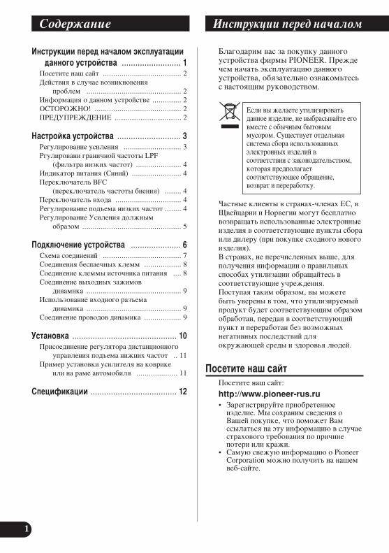
1
àÌÒÚÛ͈ËË Ô‰ ̇˜‡ÎÓÏ ˝ÍÒÔÎÛ‡Ú‡ˆËˉ‡ÌÌÓ„Ó ÛÒÚÓÈÒÚ‚‡ .......................... 1
èÓÒÂÚËÚ ̇¯ Ò‡ÈÚ ...................................... 2ÑÂÈÒÚ‚Ëfl ‚ ÒÎÛ˜‡Â ‚ÓÁÌËÍÌÓ‚ÂÌËfl
ÔÓ·ÎÂÏ .............................................. 2àÌÙÓχˆËfl Ó ‰‡ÌÌÓÏ ÛÒÚÓÈÒÚ‚Â .............. 2éëíéêéÜçé! .......................................... 2èêÖÑìèêÖÜÑÖçàÖ .................................... 2
ç‡ÒÚÓÈ͇ ÛÒÚÓÈÒÚ‚‡ ............................ 3ê„ÛÎËÓ‚‡ÌË ÛÒËÎÂÌËfl ............................ 3ê„ÛÎËÓ‚‡ÌË „‡Ì˘ÌÓÈ ˜‡ÒÚÓÚ˚ LPF
(ÙËθڇ ÌËÁÍËı ˜‡ÒÚÓÚ) ...................... 4à̉Ë͇ÚÓ ÔËÚ‡ÌËfl (ëËÌËÈ) ........................ 4èÂÂÍβ˜‡ÚÂθ BFC
(ÔÂÂÍβ˜‡ÚÂθ ˜‡ÒÚÓÚ˚ ·ËÂÌËfl) ........ 4èÂÂÍβ˜‡ÚÂθ ‚ıÓ‰‡ ................................ 4ê„ÛÎËÓ‚‡ÌË ÔÓ‰˙Âχ ÌËÁÍËı ˜‡ÒÚÓÚ ........ 4ê„ÛÎËÓ‚‡ÌË ìÒËÎÂÌËfl ‰ÓÎÊÌ˚Ï
Ó·‡ÁÓÏ ................................................ 5
èÓ‰Íβ˜ÂÌË ÛÒÚÓÈÒÚ‚‡ ...................... 6ëıÂχ ÒÓ‰ËÌÂÌËÈ ...................................... 7ëÓ‰ËÌÂÌËfl ·ÂÒԇ˜Ì˚ı ÍÎÂÏÏ .................. 8ëÓ‰ËÌÂÌË ÍÎÂÏÏ˚ ËÒÚÓ˜ÌË͇ ÔËÚ‡ÌËfl .... 8ëÓ‰ËÌÂÌË ‚˚ıÓ‰Ì˚ı Á‡ÊËÏÓ‚
‰Ë̇ÏË͇ .............................................. 9àÒÔÓθÁÓ‚‡ÌË ‚ıÓ‰ÌÓ„Ó ‡Á˙Âχ
‰Ë̇ÏË͇ .............................................. 9ëÓ‰ËÌÂÌË ÔÓ‚Ó‰Ó‚ ‰Ë̇ÏË͇ .................. 9
ìÒÚ‡Ìӂ͇ .............................................. 10èËÒÓ‰ËÌÂÌË „ÛÎflÚÓ‡ ‰ËÒڇ̈ËÓÌÌÓ„Ó
ÛÔ‡‚ÎÂÌËfl ÔÓ‰˙Âχ ÌËÊÌËı ˜‡ÒÚÓÚ .. 11èËÏ ÛÒÚ‡ÌÓ‚ÍË ÛÒËÎËÚÂÎfl ̇ ÍÓ‚ËÍÂ
ËÎË Ì‡ ‡Ï ‡‚ÚÓÏÓ·ËÎfl .................... 11
ëÔˆËÙË͇ˆËË ...................................... 12
Å·„Ó‰‡ËÏ ‚‡Ò Á‡ ÔÓÍÛÔÍÛ ‰‡ÌÌÓ„ÓÛÒÚÓÈÒÚ‚‡ ÙËÏ˚ PIONEER. èÂʉ˜ÂÏ Ì‡˜‡Ú¸ ˝ÍÒÔÎÛ‡Ú‡ˆË˛ ‰‡ÌÌÓ„ÓÛÒÚÓÈÒÚ‚‡, Ó·flÁ‡ÚÂθÌÓ ÓÁ̇ÍÓϸÚÂÒ¸Ò Ì‡ÒÚÓfl˘ËÏ ÛÍÓ‚Ó‰ÒÚ‚ÓÏ.
ó‡ÒÚÌ˚ ÍÎËÂÌÚ˚ ‚ Òڇ̇ı-˜ÎÂ̇ı EC, ‚ô‚ÂȈ‡ËË Ë çӂ„ËË ÏÓ„ÛÚ ·ÂÒÔ·ÚÌÓ‚ÓÁ‚‡˘‡Ú¸ ËÒÔÓθÁÓ‚‡ÌÌ˚ ˝ÎÂÍÚÓÌÌ˚ÂËÁ‰ÂÎËfl ‚ ÒÓÓÚ‚ÂÚÒÚ‚Û˛˘Ë ÔÛÌÍÚ˚ Ò·Ó‡ËÎË ‰ËÎÂÛ (ÔË ÔÓÍÛÔÍ ÒıÓ‰ÌÓ„Ó ÌÓ‚Ó„ÓËÁ‰ÂÎËfl).Ç Òڇ̇ı, Ì Ô˜ËÒÎÂÌÌ˚ı ‚˚¯Â, ‰ÎflÔÓÎÛ˜ÂÌËfl ËÌÙÓχˆËË Ó Ô‡‚ËθÌ˚ıÒÔÓÒÓ·‡ı ÛÚËÎËÁ‡ˆËË Ó·‡˘‡ÈÚÂÒ¸ ‚ÒÓÓÚ‚ÂÚÒÚ‚Û˛˘Ë ۘÂʉÂÌËfl.èÓÒÚÛÔ‡fl Ú‡ÍËÏ Ó·‡ÁÓÏ, ‚˚ ÏÓÊÂÚ·˚Ú¸ Û‚ÂÂÌ˚ ‚ ÚÓÏ, ˜ÚÓ ÛÚËÎËÁËÛÂÏ˚ÈÔÓ‰ÛÍÚ ·Û‰ÂÚ ÒÓÓÚ‚ÂÚÒÚ‚Û˛˘ËÏ Ó·‡ÁÓÏÓ·‡·ÓÚ‡Ì, Ô‰‡Ì ‚ ÒÓÓÚ‚ÂÚÒÚ‚Û˛˘ËÈÔÛÌÍÚ Ë Ô‡·ÓÚ‡Ì ·ÂÁ ‚ÓÁÏÓÊÌ˚ıÌ„‡ÚË‚Ì˚ı ÔÓÒΉÒÚ‚ËÈ ‰ÎflÓÍÛʇ˛˘ÂÈ Ò‰˚ Ë Á‰ÓÓ‚¸fl β‰ÂÈ.
èÓÒÂÚËÚ ̇¯ Ò‡ÈÚèÓÒÂÚËÚ ̇¯ Ò‡ÈÚ:
http://www.pioneer-rus.ru• á‡Â„ËÒÚËÛÈÚ ÔËÓ·ÂÚÂÌÌÓÂ
ËÁ‰ÂÎËÂ. å˚ ÒÓı‡ÌËÏ Ò‚Â‰ÂÌËfl ÓLJ¯ÂÈ ÔÓÍÛÔÍÂ, ˜ÚÓ ÔÓÏÓÊÂÚ Ç‡ÏÒÒ˚·ڸÒfl ̇ ˝ÚÛ ËÌÙÓχˆË˛ ‚ ÒÎÛ˜‡ÂÒÚ‡ıÓ‚Ó„Ó Ú·ӂ‡ÌËfl ÔÓ Ô˘ËÌÂÔÓÚÂË ËÎË Í‡ÊË.
• ë‡ÏÛ˛ Ò‚ÂÊÛ˛ ËÌÙÓχˆË˛ Ó PioneerCorporation ÏÓÊÌÓ ÔÓÎÛ˜ËÚ¸ ̇ ̇¯Âς·-Ò‡ÈÚÂ.
ÖÒÎË ‚˚ Ê·ÂÚ ÛÚËÎËÁËÓ‚‡Ú¸‰‡ÌÌÓ ËÁ‰ÂÎËÂ, Ì ‚˚·‡Ò˚‚‡ÈÚ „ӂÏÂÒÚÂ Ò Ó·˚˜Ì˚Ï ·˚ÚÓ‚˚ÏÏÛÒÓÓÏ. ëÛ˘ÂÒÚ‚ÛÂÚ ÓÚ‰Âθ̇flÒËÒÚÂχ Ò·Ó‡ ËÒÔÓθÁÓ‚‡ÌÌ˚ı˝ÎÂÍÚÓÌÌ˚ı ËÁ‰ÂÎËÈ ‚ÒÓÓÚ‚ÂÚÒÚ‚ËË Ò Á‡ÍÓÌÓ‰‡ÚÂθÒÚ‚ÓÏ,ÍÓÚÓ‡fl Ô‰ÔÓ·„‡ÂÚÒÓÓÚ‚ÂÚÒÚ‚Û˛˘Â ӷ‡˘ÂÌËÂ,‚ÓÁ‚‡Ú Ë Ô‡·ÓÚÍÛ.
ëÓ‰ÂʇÌË àÌÒÚÛ͈ËË Ô‰ ̇˜‡ÎÓÏ

EN
GLIS
HES
PA
ÑO
LD
EU
TS
CH
FR
AN
ÇA
ISIT
ALIA
NO
NED
ERLA
ND
Sê
ìë
ëä
àâ
2
ÑÂÈÒÚ‚Ëfl ‚ ÒÎÛ˜‡Â ‚ÓÁÌËÍÌÓ‚ÂÌËfl ÔÓ·ÎÂÏÖÒÎË ÛÒÚÓÈÒÚ‚Ó Ì ‡·ÓÚ‡ÂÚ ‰ÓÎÊÌ˚ÏÓ·‡ÁÓÏ, Ò‚flÊËÚÂÒ¸ Ò ‚‡¯ËÏ ‰ËÎÂÓÏËÎË ·ÎËʇȯÂÈ ÛÚ‚ÂʉÂÌÌÓÈÒڇ̈ËÂÈ Ó·ÒÎÛÊË‚‡ÌËfl ÔÓ‰Û͈ËËPIONEER.
àÌÙÓχˆËfl Ó ‰‡ÌÌÓÏ ÛÒÚÓÈÒÚ‚ÂчÌÌÓ ÛÒÚÓÈÒÚ‚Ó Ô‰ÒÚ‡‚ÎflÂÚ ÒÓ·ÓÈÛÒËÎËÚÂθ Í·ÒÒ‡ D ‰ÎflÌËÁÍÓ˜‡ÒÚÓÚÌÓ„Ó ‰Ë̇ÏË͇. ÖÒÎËÔÓ‰Íβ˜ËÚ¸ Í RCA ‚ıÓ‰Û ‰‡ÌÌÓ„ÓÔÓ‰ÛÍÚ‡ Ë Î‚˚È (L), Ë Ô‡‚˚È (R)͇̇Î, ÚÓ ‚˚ıÓ‰ÌÓÈ Ò˄̇Π·Û‰ÂÚÒϯ˂‡Ú¸Òfl, ÔÓÒÍÓθÍÛ ‰‡ÌÌ˚ÈÛÒËÎËÚÂθ – ÏÓÌÓÙÓÌ˘ÂÒÍËÈ.
éëíéêéÜçé!• çËÍÓ„‰‡ Ì Á‡ÏÂÌflÈÚ Ô„ӂ¯ËÈ
Ô‰Óı‡ÌËÚÂθ Ô‰Óı‡ÌËÚÂÎÂÏ Ò ·Ó±Î¸¯ËÏÌÓÏË̇ÎÓÏ. àÒÔÓθÁÓ‚‡ÌË ÌÂÔÓ‰ıÓ‰fl˘Â„ÓÔ‰Óı‡ÌËÚÂÎfl ÏÓÊÂÚ ÔË‚ÂÒÚË Í Ô„‚ÛË ‚˚‰ÂÎÂÌ˲ ‰˚χ. ùÚÓ Ú‡ÍÊ ÏÓÊÂÚÔË‚ÂÒÚË Í ÔÓ‚ÂʉÂÌ˲ ÛÒÚÓÈÒÚ‚‡ ËÚ‡‚χÏ, ‚ ÚÓÏ ˜ËÒΠÓÊÓ„‡Ï.
• àÒÔÓθÁÛÈÚ ÔÓÒÚ‡‚ÎflÂÏ˚È ¯ÂÒÚËÛ„ÓθÌ˚È„‡Â˜Ì˚È Íβ˜, ˜ÚÓ·˚ Á‡ÚflÌÛÚ¸ ‚ËÌÚ˚, ÍÓ„‰‡ÒÓ‰ËÌflÂÚ ÔÓ‚Ó‰‡ Ò ÍÎÂÏÏÓÈ.àÒÔÓθÁÓ‚‡ÌË ‰ÎËÌÌÓ„Ó, ÒÂËÈÌÓ‚˚ÔÛÒ͇ÂÏÓ„Ó ¯ÂÒÚËÛ„ÓθÌÓ„Ó „‡Â˜ÌÓ„ÓÍβ˜‡ ÏÓÊÂÚ ÒÚ‡Ú¸ Ô˘ËÌÓÈ ÔËÏÂÌÂÌËfl˜ÂÁÏÂÌÓ„Ó ‚‡˘‡˛˘Â„Ó ÏÓÏÂÌÚ‡,‚ÓÁÏÓÊÌÓ ÔË‚Ó‰fl˘Â„Ó Í ÔÓ‚ÂʉÂÌ˲ÍÎÂÏÏ Ë ÔÓ‚Ó‰Ó‚.
èêÖÑìèêÖÜÑÖçàÖ• å˚ ÂÍÓÏẨÛÂÏ, ˜ÚÓ·˚ Ç˚ ËÒÔÓθÁÓ‚‡ÎË
ÒÔˆˇθÌ˚ ͇ÒÌ˚ ÔÓ‚Ó‰‡ [RD-228] ‰Îfl·‡Ú‡ÂË Ë Á‡ÁÂÏÎÂÌËfl, ÍÓÚÓ˚ ÔÓ‰‡˛ÚÒflÓÚ‰ÂθÌÓ. èÓ‰ÒÓ‰ËÌËÚ ˝ÎÂÍÚ˘ÂÒÍËÈÔÓ‚Ó‰ ·‡Ú‡ÂË ÔflÏÓ Í ÔÓÎÓÊËÚÂθÌÓÈÍÎÂÏÏ (+) ·‡Ú‡ÂË ‡‚ÚÓÏÓ·ËÎfl, ‡ ÔÓ‚Ó‰Á‡ÁÂÏÎÂÌËfl Í ÍÛÁÓ‚Û ‡‚ÚÓÏÓ·ËÎfl.
• ç ÔË͇҇ÈÚÂÒ¸ Í ÛÒËÎËÚÂβ ‚·ÊÌ˚ÏËÛ͇ÏË, Ú‡Í Í‡Í ˝ÚÓ ÏÓÊÂÚ ÔË‚ÂÒÚË ÍÔÓ‡ÊÂÌ˲ ˝ÎÂÍÚ˘ÂÒÍËÏ ÚÓÍÓÏ. í‡ÍÊ ÌÂÒΉÛÂÚ ‰ÓÚ‡„Ë‚‡Ú¸Òfl ‰Ó ÛÒËÎËÚÂÎfl, ÂÒÎË Ì‡ÌÂ„Ó ÔÓԇ· ͇͇fl-ÎË·Ó ÊˉÍÓÒÚ¸.
• ÑÎfl Ó·ÂÒÔ˜ÂÌËfl ·ÂÁÓÔ‡ÒÌÓÒÚË ‰‚ËÊÂÌËfl Ë·ÂÁÓÔ‡ÒÌ˚ı ÛÒÎÓ‚ËÈ ‚ÓʉÂÌËfl ÛÒÚ‡ÌÓ‚ËÚÂÚ‡ÍÓÈ ÛÓ‚Â̸ „ÓÏÍÓÒÚË, ÔË ÍÓÚÓÓÏ ‚‡Ï·Û‰ÂÚ ÒÎ˚¯ÂÌ Ó·˚˜Ì˚È ¯ÛÏ ‰ÓÓÊÌÓ„Ó‰‚ËÊÂÌËfl.
• ÖÒÎË Ô„ÓËÚ Ô‰Óı‡ÌËÚÂθ ÓÚ‰ÂθÌÓÔÓ‰‡‚‡ÂÏÓ„Ó ÔÓ‚Ó‰‡ ·‡Ú‡ÂË ËÎËÔ‰Óı‡ÌËÚÂθ ÛÒËÎËÚÂÎfl, Ôӂ¸ÚÂÒÓ‰ËÌÂÌËfl ËÒÚÓ˜ÌË͇ ÔËÚ‡ÌËfl ËÌËÁÍÓ˜‡ÒÚÓÚÌÓ„Ó ‰Ë̇ÏË͇. éÔ‰ÂÎËÚ ËÛÒÚ‡ÌËÚ Ô˘ËÌÛ, Á‡ÚÂÏ Á‡ÏÂÌËÚÂÔ‰Óı‡ÌËÚÂθ ÌÓ‚˚Ï Ô‰Óı‡ÌËÚÂÎÂÏÚ‡ÍÓ„Ó Ê ‡Áχ Ë ÌÓÏË̇·.
• ÑÎfl ÚÓ„Ó, ˜ÚÓ·˚ Ô‰ÓÚ‚‡ÚËÚ¸ ‚˚ıÓ‰ ËÁÒÚÓfl ÛÒËÎËÚÂÎfl Ë ÌËÁÍÓ˜‡ÒÚÓÚÌÓ„Ó‰Ë̇ÏË͇, ÔË ‚ÓÁÌËÍÌÓ‚ÂÌËË ÌÂÒڇ̉‡ÚÌ˚ıÛÒÎÓ‚ËÈ Á‡˘ËÚ̇fl ˆÂÔ¸ ÔÂ͇ÚËÚ ÔÓ‰‡˜ÛÔËÚ‡ÌËfl ̇ ÛÒËÎËÚÂθ (ÔË ˝ÚÓÏ ÔÂ͇ÚËÚÒfl‚ÓÒÔÓËÁ‚‰ÂÌË Á‚Û͇). Ç ˝ÚÓÏ ÒÎÛ˜‡ÂÒΉÛÂÚ ÓÚÍβ˜ËÚ¸ ˝ÎÂÍÚÓÔËÚ‡ÌË ÒËÒÚÂÏ˚Ë ÔÓ‚ÂËÚ¸ ÒÓ‰ËÌÂÌË ËÒÚÓ˜ÌË͇ ÔËÚ‡ÌËfl ËÌËÁÍÓ˜‡ÒÚÓÚÌÓ„Ó ‰Ë̇ÏË͇. éÔ‰ÂÎËÚ ËÛÒÚ‡ÌËÚ Ô˘ËÌÛ ÌÂËÒÔ‡‚ÌÓÒÚË.
• ë‚flÊËÚÂÒ¸ Ò ‰ËÎÂÓÏ, ÂÒÎË ‚˚ Ì ÏÓÊÂÚÂÓÔ‰ÂÎËÚ¸ Ô˘ËÌÛ ÌÂËÒÔ‡‚ÌÓÒÚË.
• ÇÓ ËÁ·ÂʇÌË ÔÓ‡ÊÂÌËfl ˝ÎÂÍÚ˘ÂÒÍËÏÚÓÍÓÏ ËÎË ÍÓÓÚÍÓ„Ó Á‡Ï˚͇ÌËfl ‚Ó ‚ÂÏflÔÓ‰Íβ˜ÂÌËfl Ë ÛÒÚ‡ÌÓ‚ÍË Ô‰ ‚˚ÔÓÎÌÂÌËÂχ·ÓÚ ÒΉÛÂÚ Ó·flÁ‡ÚÂθÌÓ ÓÚÒÓ‰ËÌËÚ¸ÓÚˈ‡ÚÂθÌÛ˛ (–) ÍÎÂÏÏÛ ·‡Ú‡ÂË.
• èË ÔÓÒ‚ÂÎË‚‡ÌËË ÓÚ‚ÂÒÚËÈ ‰Îfl ÛÒÚ‡ÌÓ‚ÍËÛÒËÎËÚÂÎfl ۷‰ËÚÂÒ¸ ‚ ÚÓÏ, ˜ÚÓ Á‡ Ô‡ÌÂθ˛ Ì‡ÒÔÓÎÓÊÂÌ˚ ͇ÍËÂ-ÎË·Ó ‰ÂÚ‡ÎË.é·flÁ‡ÚÂθÌÓ Á‡˘ËÚËÚ ÓÚ ‚ÓÁÏÓÊÌ˚ıÔÓ‚ÂʉÂÌËÈ ‚Ò ͇·ÂÎË Ë ‚‡ÊÌÓÂÓ·ÓÛ‰Ó‚‡ÌËÂ, ̇ÔËÏ ÚÛ·ÍË ÚÓÔÎË‚ÌÓÈ ËÚÓÏÓÁÌÓÈ ÒËÒÚÂÏ Ë ˝ÎÂÍÚÓÔÓ‚Ó‰ÍÛ.
• çÖ ìëíÄçÄÇãàÇÄâíÖ ÛÒËÎËÚÂθ ‚ Ú‡ÍËıÏÂÒÚ‡ı, „‰Â ̇ ÌÂ„Ó ÏÓ„ÛÚ ÔÓÔ‡‰‡Ú¸ ͇ÍËÂ-ÎË·Ó ÊˉÍÓÒÚË, Ú‡Í Í‡Í ˝ÚÓ ÏÓÊÂÚ ÔË‚ÂÒÚË ÍÔÓ‡ÊÂÌ˲ ˝ÎÂÍÚ˘ÂÒÍËÏ ÚÓÍÓÏ. äÓÏÂÚÓ„Ó, ÍÓÌÚ‡ÍÚ Ò ÊˉÍÓÒÚ¸˛ ÏÓÊÂÚ ÔË‚ÂÒÚË ÍÔÓ‚ÂʉÂÌ˲ ÛÒËÎËÚÂÎfl Ë ‰Ë̇ÏËÍÓ‚,‚˚‰ÂÎÂÌ˲ ‰˚χ Ë Ô„‚Û. èË ˝ÚÓÏÔÓ‚ÂıÌÓÒÚ¸ ÛÒËÎËÚÂÎfl Ë ÔÓ‰Íβ˜ÂÌÌ˚ı ÍÌÂÏÛ ‰Ë̇ÏËÍÓ‚ ÏÓÊÂÚ Ì‡„ÂÚ¸Òfl ËÔËÍÓÒÌÓ‚ÂÌËÂ Í ÌÂÈ ÏÓÊÂÚ ÔË‚ÂÒÚË ÍÌÂÁ̇˜ËÚÂθÌ˚Ï ÓÊÓ„‡Ï.
˝ÍÒÔÎÛ‡Ú‡ˆËË ‰‡ÌÌÓ„Ó ÛÒÚÓÈÒÚ‚‡

3
ç‡ÒÚÓÈ͇ ÛÒÚÓÈÒÚ‚‡
ê„ÛÎËÓ‚‡ÌË ÛÒËÎÂÌËfl
ÖÒÎË ‰‡Ê ÔË ÔË·‡‚ÎÂÌËË „ÓÏÍÓÒÚË ‡‚ÚÓÏÓ·ËθÌÓÈ Ï‡„ÌËÚÓÎ˚,ËÒÔÓθÁÛ˛˘ÂÈÒfl Ò ‰‡ÌÌ˚Ï ÛÒËÎËÚÂÎÂÏ ÏÓ˘ÌÓÒÚË, ÛÓ‚Â̸ Á‚Û͇ÓÒÚ‡ÂÚÒfl ÌËÁÍËÏ, ÔÓ‚ÂÌËÚ ÔÓ ˜‡ÒÓ‚ÓÈ ÒÚÂÎÍ „ÛÎflÚÓ ÛÒËÎÂÌËfl.ÖÒÎË ÔË ÔË·‡‚ÎÂÌËË „ÓÏÍÓÒÚË ÔÓËÒıÓ‰ËÚ ËÒ͇ÊÂÌË Á‚Û͇, ÔÓ‚ÂÌËÚ„ÛÎflÚÓ ÛÒËÎÂÌËfl ÔÓÚË‚ ˜‡ÒÓ‚ÓÈ ÒÚÂÎÍË.• èË ËÒÔÓθÁÓ‚‡ÌËË Ï‡„ÌËÚÓÎ˚ Ò ‡Á˙ÂχÏË RCA (Òڇ̉‡ÚÌ˚È ‚˚ıÓ‰ÌÓÈ Ò˄̇Î
500 ÏÇ), ÛÒÚ‡ÌÓ‚ËÚ ˝ÚË Â„ÛÎflÚÓ˚ ‚ ÔÓÎÓÊÂÌË NORMAL. èË ËÒÔÓθÁÓ‚‡Ìˡ‚ÚÓÏÓ·ËθÌÓÈ Ï‡„ÌËÚÓÎ˚ Pioneer Ò ‡Á˙ÂχÏË RCA Ò Ï‡ÍÒËχθÌ˚Ï‚˚ıÓ‰Ì˚Ï Ò˄̇ÎÓÏ 4 Ç ËÎË ‚˚¯Â, ÓÚ„ÛÎËÛÈÚ ÛÓ‚Â̸ ‚ ÒÓÓÚ‚ÂÚÒÚ‚ËË ÒÛÓ‚ÌÂÏ ‚˚ıÓ‰ÌÓ„Ó Ò˄̇· ‡‚ÚÓÏÓ·ËθÌÓÈ Ï‡„ÌËÚÓÎ˚.
EN
GLIS
HES
PA
ÑO
LD
EU
TS
CH
FR
AN
ÇA
ISIT
ALIA
NO
NED
ERLA
ND
Sê
ìë
ëä
àâ
4
ê„ÛÎËÓ‚‡ÌË „‡Ì˘ÌÓÈ ˜‡ÒÚÓÚ˚ LPF (ÙËÎ Ú‡ ÌËÁÍËı ˜‡ÒÚÓÚ)
åÓÊÌÓ ‚˚·‡Ú¸ „‡Ì˘ÌÛ˛ ˜‡ÒÚÓÚÛ ‚ ‰Ë‡Ô‡ÁÓÌ ÓÚ 40 Ɉ ‰Ó 240 Ɉ.
èÂÂÍβ˜‡ÚÂθ BFC (ÔÂÂÍβ˜‡ÚÂθ ˜‡ÒÚÓÚ˚ ·ËÂÌËfl)
ÖÒÎË ÔË ÔÓÒÎۯ˂‡ÌËË Ì‡ ‚‡¯ÂÈ ‡‚ÚÓÏÓ·ËθÌÓÈ Ï‡„ÌËÚÓΠÒ˄̇· ‡‰ËÓÒڇ̈ËȉˇԇÁÓ̇ Ò‰ÌËı/‰ÎËÌÌ˚ı ‚ÓÎÌ ÒÎ˚¯ËÚÒfl ·ËÂÌËÂ, ËÁÏÂÌËÚ ÔÓÎÓÊÂÌËÂÔÂÂÍβ˜‡ÚÂÎfl BFC ÔË ÔÓÏÓ˘Ë Òڇ̉‡ÚÌÓÈ ÓÚ‚ÂÚÍË.
ê„ÛÎËÓ‚‡ÌË ÔÓ‰˙Âχ ÌËÁÍËı ˜‡ÒÚÓÚ
Ç˚ ÏÓÊÂÚ „ÛÎËÓ‚‡Ú¸ ÛÓ‚Â̸ ÔÓ‰˙Âχ ÌËÁÍËı ˜‡ÒÚÓÚ ÓÚ 0 ‰Å ‰Ó 12 ‰Å.àÌÒÚÛ͈ËË ÔÓ ÔÓ‰Íβ˜ÂÌ˲ ÛÒÚÓÈÒÚ‚‡ ‰Îfl ‰ËÒڇ̈ËÓÌÌÓ„Ó ÛÔ‡‚ÎÂÌËfl ÔÓ‰˙ÂÏÓÏÌËÁÍËı ˜‡ÒÚÓÚ Í ÛÒËÎËÚÂβ Ô˂‰ÂÌ˚ ‚ ‡Á‰ÂΠ“ëıÂχ ÒÓ‰ËÌÂÌËÈ”.
à̉Ë͇ÚÓ ÔËÚ‡ÌËfl (ëËÌËÈ)à̉Ë͇ÚÓ ÔËÚ‡ÌËfl Á‡ÊË„‡ÂÚÒfl ÔË ÔÓ‰‡˜Â ˝ÎÂÍÚÓÔËÚ‡ÌËfl.
èÂÂÍβ˜‡ÚÂθ ‚ıÓ‰‡ÇÓÁÏÓÊÂÌ ‚‚Ó‰ ÓÚ ‚̯ÌÂ„Ó ‚˚ıÓ‰ÌÓ„Ó ‡Á˙Âχ ‡‚ÚÓÏÓ·ËθÌÓÈ Ï‡„ÌËÚÓÎ˚ ËÎË ÓÚ‚˚ıÓ‰ÌÓ„Ó ‡Á˙Âχ ‰Ë̇ÏË͇ ‡‚ÚÓÏÓ·ËθÌÓÈ Ï‡„ÌËÚÓÎ˚. èÂÂÍβ˜ËÚ ‚ıÓ‰ÌÓÈÔÂÂÍβ˜‡ÚÂθ ‰Ó ‚Íβ˜ÂÌËfl ÔËÚ‡ÌËfl. èÓÒΠÔÂÂÍβ˜ÂÌËfl ‚ıÓ‰ÌÓ„ÓÔÂÂÍβ˜‡ÚÂÎfl, ÔÓ͇ ÏÓ˘ÌÓÒÚ¸ ÏÓÊÂÚ ·˚Ú¸ ËÒÚÓ˜ÌËÍÓÏ „ÓÏÍÓ„Ó ¯Ûχ ËÁ‰‡‚‡ÂÏÓ„Ó‰Ë̇ÏË͇ÏË, ÏÓ˘ÌÓÒÚ¸ ÓÚÍβ˜‡ÂÚÒfl Á‡˘ËÚÌÓÈ ÙÛÌ͈ËÂÈ. äÓ„‰‡ ËÒÔÓθÁÛÂÚÒfl‚̯ÌËÈ ‚˚ıÓ‰ÌÓÈ ‡Á˙ÂÏ Ò‰‚Ë̸Ú ÔÂÂÍβ˜‡ÚÂθ ‚Ô‡‚Ó (RCA). ÑÎfl ÒÓ‰ËÌÂÌËÈ ÔÓËÌÒÚÛ͈ËË, ÒÏÓÚËÚ ‡Á‰ÂÎ “ëıÂχ ÒÓ‰ËÌÂÌËÈ”. äÓ„‰‡ ËÒÔÓθÁÛÂÚÒfl ‚˚ıÓ‰ÌÓȇÁ˙ÂÏ ‰Ë̇ÏË͇, Ò‰‚Ë̸Ú ÔÂÂÍβ˜‡ÚÂθ ‚ÎÂ‚Ó (SP). Ç ˝ÚÓÏ ÒÎÛ˜‡Â, ÌÂÓ·ıÓ‰ËÏÓËÒÔÓθÁÓ‚‡Ú¸ ÔÓÒÚ‡‚ÎflÂÏ˚È ÔÓ‚Ó‰ ‚ıÓ‰ÌÓ„Ó ‡Á˙Âχ ‰Ë̇ÏË͇ ÒÓ ¯ÚÂÍÂÓÏ ¯ÌÛ‡RCA. èÓ‰Ó·ÌÓ ÒÏÓÚËÚ ‡Á‰ÂÎ “àÒÔÓθÁÓ‚‡ÌË ‚ıÓ‰ÌÓ„Ó ‡Á˙Âχ ‰Ë̇ÏË͇”.

5
ç‡ÒÚÓÈ͇ ÛÒÚÓÈÒÚ‚‡
ê„ÛÎËÓ‚‡ÌË ìÒËÎÂÌËfl ‰ÓÎÊÌ˚ÏÓ·‡ÁÓÏ• ùÚÓÚ ÔË·Ó Ó·ÓÛ‰Ó‚‡Ì Á‡˘ËÚÌÓÈ ÙÛÌ͈ËÂÈ,
Ì ‰ÓÔÛÒÚËÚ¸ Ò·ÓÈ ‚ ‡·ÓÚ ҇ÏÓ„Ó ÔË·Ó‡ ˉË̇ÏËÍÓ‚ ÓÚ ÒÎ˯ÍÓÏ ·Óθ¯Ó„Ó ÍÓ΢ÂÒÚ‚‡‚˚‚Ó‰‡, ÌÂÔ‡‚ËθÌÓ„Ó ËÒÔÓθÁÓ‚‡ÌËfl ËÎËÌÂÔÓ‰ıÓ‰fl˘ÂÈ Ò‚flÁË.
• äÓ„‰‡ Á‚ÛÍÓ‚ÓÈ ‚˚‚Ó‰ ‚ ·Óθ¯ÓÏ Ó·˙ÂÏ ËÚ.‰., ˝Ú‡ ÙÛÌ͈Ëfl ÓÚÍβ˜‡ÂÚ Á‚ÛÍÓ‚ÓÈ ‚˚‚Ó‰˜ÂÂÁ ÌÂÒÍÓθÍÓ ÒÂÍÛ̉. çÓ ˝ÚÓ Ì ҷÓÈ ‚‡·ÓÚÂ. äÓ„‰‡ Ç˚ ÛÏÂ̸¯ËÚ ÛÓ‚Â̸„ÓÏÍÓÒÚË ÒËÎÓ‚ÓÈ „ÓÎÓ‚ÍË, Á‚ÛÍÓ‚ÓÈ ‚˚‚Ó‰·Û‰ÂÚ ‚ÓÒÒÚ‡ÌÓ‚ÎÂÌ.
• äÓ„‰‡ Á‚ÛÍÓ‚ÓÈ ‚˚‚Ó‰ ÓÚÍβ˜ÂÌ, ÍÓÌÚÓθÛÒËÎÂÌËfl ˝ÚÓ„Ó ÔË·Ó‡ ÏÓÊÂÚ ·˚Ú¸ÌÂÔ‡‚ËθÌÓ ÛÒÚ‡ÌÓ‚ÎÂÌ. ÑÎfl Ó·ÂÒÔ˜ÂÌËflÛ‚Â΢ÂÌËfl Ó·˙Âχ ÌÂÔÂ˚‚ÌÓ„Ó Á‚ÛÍÓ‚Ó„Ó‚˚‚Ó‰‡ ÒËÎÓ‚ÓÈ „ÓÎÓ‚ÍË ÛÒÚ‡ÌÓ‚ËÚ ÍÓÌÚÓθÛÒËÎÂÌËfl ÛÒËÎËÚÂÎfl ‚ ÔÓ‰ıÓ‰fl˘Û˛ ÔÓÁËˆË˛ÒÓÓÚ‚ÂÚÒÚ‚ÂÌÌÓ Ò Ï‡ÍÒËχθÌ˚Ï ‚˚ıÓ‰Ì˚ÏÛÓ‚ÌÂÏ Ô‰‚‡ËÚÂθÌÓ„Ó ‚˚‚Ó‰‡ ÒËÎÓ‚ÓÈ„ÓÎÓ‚ÍË.
äÓÌÚÓθ ÛÒËÎÂÌËfl ‰‡ÌÌÓ„Ó ÔË·Ó‡
• Ç˚¯ÂÔ˂‰ÂÌ̇fl ËÎβÒÚ‡ˆËfl ÔÓ͇Á˚‚‡ÂÚÛÒÚ‡ÌÓ‚ÍÛ ÛÒËÎÂÌËfl ̇ NORMAL.
çÂÚ ÌÂÓ·ıÓ‰ËÏÓÒÚË ÛÏÂ̸¯‡Ú¸ ÛÓ‚Â̸„ÓÏÍÓÒÚË ÒËÎÓ‚ÓÈ „ÓÎÓ‚ÍË, ‡ ÒÎ˯ÍÓÏ ‚˚ÒÓÍËÈ‚˚‚Ó‰ ÏÓÊÂÚ ·˚Ú¸ ÔÓÍÓÌÚÓÎËÓ‚‡Ì.
éÚÌÓ¯ÂÌË ÏÂÊ‰Û ÛÒËÎÂÌËÂÏ ÛÒËÎËÚÂÎfl Ë‚˚ıÓ‰ÌÓÈ ÏÓ˘ÌÓÒÚ¸˛ ÒËÎÓ‚ÓÈ „ÓÎÓ‚ÍË
• ÖÒÎË Ç˚ ÔÓ‚˚ÒËÚ ÛÒËÎÂÌË ÛÒËÎËÚÂÎfl ̇ÌÂÔ‡‚ËθÌ˚È ÛÓ‚Â̸, Û‚Â΢ËÚÒfl ÚÓθÍÓËÒ͇ÊÂÌËÂ, ‡ ÏÓ˘ÌÓÒÚ¸ Û‚Â΢ËÚÒflÌÂÁ̇˜ËÚÂθÌÓ.
îÓχ Ò˄̇·, ÍÓ„‰‡ ‚˚‚Ó‰ËÚÒfl ‚˚ÒÓÍËÈÛÓ‚Â̸ „ÓÏÍÓÒÚË ÍÓÌÚÓÎÂÏ ÛÒËÎÂÌËflÛÒËÎËÚÂÎfl
• ë ‚˚ÒÓÍËÏ ‚˚ıÓ‰ÓÏ ÙÓχ Ò˄̇·ËÒ͇ʇÂÚÒfl, ÂÒÎË Ç˚ ÔÓ‚˚ÒËÚ ÛÒËÎÂÌËÂÛÒËÎËÚÂÎfl, ÚÓ ÏÓ˘ÌÓÒÚ¸ ËÁÏÂÌËÚÒflÌÂÁ̇˜ËÚÂθÌÓ.
• ïÓÚfl Ç˚ ÛÏÂ̸¯‡ÂÚ ÛÓ‚Â̸ „ÓÏÍÓÒÚËÒËÎÓ‚ÓÈ „ÓÎÓ‚ÍË Ë ÛÒڇ̇‚ÎË‚‡ÂÚ ÍÓÌÚÓθÛÒËÎÂÌËfl ÛÒËÎËÚÂÎfl ‚ ÔÓ‰ıÓ‰fl˘Û˛ ÔÓÁËˆË˛,‡ Á‚ÛÍ ‚ÂÏfl ÓÚ ‚ÂÏÂÌË ÔÓÔ‡‰‡ÂÚ,ÔÓʇÎÛÈÒÚ‡, Ò‚flÊËÚÂÒ¸ Ò ·ÎËʇȯÂȇ‚ÚÓËÁËÓ‚‡ÌÌÓÈ PIONEER STATION.
çÓχθÌÓ ÛÒËÎÂÌË å‡ÍÒËχθÌÓ ÛÒËÎÂÌËÂ
ìÒËÎËÚÂθ ÛÒËÎÂÌËfl(ÌÓχθÌÓ)
ìÒËÎËÚÂθ ÛÒËÎÂÌËfl(χÍÒËχθÌÓ)
îÓχÒ˄̇·
îÓχÒ˄̇·
ꇂ̇fl ÏÓ˘ÌÓÒÚ¸
çÓχθÌÓ ÛÒËÎÂÌË å‡ÍÒËχθÌÓ ÛÒËÎÂÌËÂ
ìÒËÎËÚÂθ ÛÒËÎÂÌËfl(ÌÓχθÌÓ)
ìÒËÎËÚÂθ ÛÒËÎÂÌËfl(χÍÒËχθÌÓ)
ëÚÛÔÂÌË ÛÓ‚Ìfl „ÓÏÍÓÒÚËÒËÎÓ‚ÓÈ „ÓÎÓ‚ÍË
åÓ˘ÌÓÒÚ¸ åÓ˘ÌÓÒÚ¸
ëÚÛÔÂÌË ÛÓ‚Ìfl „ÓÏÍÓÒÚËÒËÎÓ‚ÓÈ „ÓÎÓ‚ÍË
ꇂ̇fl ÏÓ˘ÌÓÒÚ¸
ìÓ‚Â̸Ô‰‚‡ËÚÂθÌÓ„Ó‚˚‚Ó‰‡: 2 Ç(ëڇ̉‡Ú: 500 ÏÇ)
ìÓ‚Â̸Ô‰‚‡ËÚÂθÌÓ„Ó‚˚‚Ó‰‡: 4 Ç
ìÓ‚Â̸Ô‰‚‡ËÚÂθÌÓ„Ó‚˚‚Ó‰‡: 6,5 Ç

èÓ‰Íβ˜ÂÌË ÛÒÚÓÈÒÚ‚‡
6
EN
GLIS
HES
PA
ÑO
LD
EU
TS
CH
FR
AN
ÇA
ISIT
ALIA
NO
NED
ERLA
ND
Sê
ìë
ëä
àâ
éëíéêéÜçé!• éÚÒÓ‰ËÌËÚ ÓÚˈ‡ÚÂθÌÛ˛ (–) ÍÎÂÏÏÛ
·‡Ú‡ÂË, ˜ÚÓ·˚ Ì ‰ÓÔÛÒÚËÚ¸ ÍÓÓÚÍÓ„ÓÁ‡Ï˚͇ÌËfl Ë ÔÓ‚ÂʉÂÌËfl ÛÒÚÓÈÒÚ‚‡.
• á‡ÍÂÔËÚ ÔÓ‚Ó‰‡ ͇·ÂθÌ˚ÏË Á‡ÊËχÏËËÎË ÎËÔÍÓÈ ÎÂÌÚÓÈ. ÑÎfl Á‡˘ËÚ˚ ÔÓ‚Ó‰Ó‚ÒΉÛÂÚ Ó·ÏÓÚ‡Ú¸ Ëı ÎËÔÍÓÈ ÎÂÌÚÓÈ ‚ ÚÂıÏÂÒÚ‡ı, „‰Â ÓÌË ÒÓÔË͇҇˛ÚÒfl ÒÏÂÚ‡Î΢ÂÒÍËÏË ˜‡ÒÚflÏË.
• ç ‡ÒÔÓ·„‡ÈÚ ÔÓ‚Ó‰‡ ‚ ÏÂÒÚ‡ı,ÔÓ‰‚ÂÊÂÌÌ˚ı ‚ÓÁ‰ÂÈÒڂ˲ ‚˚ÒÓÍÓÈÚÂÏÔ‡ÚÛ˚, ̇ÔËÏ ‚ Ú‡ÍÓÏ ÏÂÒÚÂ, „‰Â ̇ÌËı ÏÓÊÂÚ ‰ÂÈÒÚ‚Ó‚‡Ú¸ ̇„ÂÚ˚È ‚ÓÁ‰Ûı ËÁӷӄ‚‡ÚÂÎfl. 燄‚‡ÌË ÏÓÊÂÚ ÔË‚ÂÒÚË ÍÔÓ‚ÂʉÂÌ˲ ËÁÓÎflˆËË, ‚ ÂÁÛθڇÚ ˜Â„ÓÏÓÊÂÚ ÔÓËÁÓÈÚË ÍÓÓÚÍÓ Á‡Ï˚͇ÌË ̇ÍÓÔÛÒ ‡‚ÚÓÏÓ·ËÎfl.
• ì·Â‰ËÚÂÒ¸ ‚ ÚÓÏ, ˜ÚÓ ÔÓ‚Ó‰‡ ̠ϯ‡˛Ú‰‚Ë„‡˛˘ËÏÒfl ˜‡ÒÚflÏ ‡‚ÚÓÏÓ·ËÎfl, ̇ÔËÏÂ,˚˜‡„Û ÔÂÂÍβ˜ÂÌËfl ÍÓÓ·ÍË Ô‰‡˜,Û˜ÌÓÏÛ ÚÓÏÓÁÛ ËÎË ÏÂı‡ÌËÁÏÛÔ‰‚ËÊÂÌËfl ÒˉÂÌËÈ.
• ç ÛÍÓ‡˜Ë‚‡ÈÚ ͇ÍËÂ-ÎË·Ó ÔÓ‚Ó‰‡. èËÛÍÓ‡˜Ë‚‡ÌËË ÔÓ‚Ó‰‡ ˆÂÔ¸ Á‡˘ËÚ˚ ÏÓÊÂÚ ÌÂÒ‡·ÓÚ‡Ú¸ ‚ ÌÛÊÌ˚È ÏÓÏÂÌÚ.
• çËÍÓ„‰‡ Ì ÔÓ‰‡‚‡ÈÚ ˝ÎÂÍÚÓÔËÚ‡ÌË ̇‰Û„Ó ӷÓÛ‰Ó‚‡ÌË ÔÓÒ‰ÒÚ‚ÓÏ ÒÌflÚËflËÁÓÎflˆËË ÔÓ‚Ó‰‡, ÔÓ ÍÓÚÓÓÏÛ ÔÓ‰‡ÂÚÒfl˝ÎÂÍÚÓÔËÚ‡ÌËÂ, Ë ÔÓ‰Íβ˜ÂÌËfl Í ˝ÚÓÏÛÔÓ‚Ó‰Û. èÓÔÛÒÍ̇fl ÒÔÓÒÓ·ÌÓÒÚ¸ ÔÓ‚Ó‰‡ ÔÓÚÓÍÛ ·Û‰ÂÚ Ô‚˚¯Â̇, ˜ÚÓ Ô˂‰ÂÚ ÍÔ„‚Û.
• çËÍÓ„‰‡ Ì Á‡ÏÂÌflÈÚ Ô„ӂ¯ËÈÔ‰Óı‡ÌËÚÂθ Ô‰Óı‡ÌËÚÂÎÂÏ Ò ·Ó±Î¸¯ËÏÌÓÏË̇ÎÓÏ. àÒÔÓθÁÓ‚‡ÌË ÌÂÔÓ‰ıÓ‰fl˘Â„ÓÔ‰Óı‡ÌËÚÂÎfl ÏÓÊÂÚ ÔË‚ÂÒÚË Í Ô„‚ÛË ‚˚‰ÂÎÂÌ˲ ‰˚χ. ùÚÓ Ú‡ÍÊ ÏÓÊÂÚÔË‚ÂÒÚË Í ÔÓ‚ÂʉÂÌ˲ ÛÒÚÓÈÒÚ‚‡ ËÚ‡‚χÏ, ‚ ÚÓÏ ˜ËÒΠÓÊÓ„‡Ï.
éëíéêéÜçé!àÌÒÚÛ͈ËË ÔÓ Ô‰ÛÔÂʉÂÌ˲ÔÓ‚ÂʉÂÌËÈ Ë/ËÎË Ú‡‚Ï• çËÍÓ„‰‡ Ì Á‡ÁÂÏÎflÈÚ ÔÓ‚Ó‰ ‰Ë̇ÏË͇
ÌÂÔÓÒ‰ÒÚ‚ÂÌÌÓ Ë Ì ÔÓ‰Íβ˜‡ÈÚÂÓÚˈ‡ÚÂθÌ˚È (–) ÔÓ‚Ó‰ Í ÌÂÒÍÓθÍËωË̇ÏË͇Ï.
• чÌÌÓ ÛÒÚÓÈÒÚ‚Ó Ô‰̇Á̇˜ÂÌÓ ‰Îfl‡‚ÚÓÏÓ·ËÎÂÈ Ò ·‡Ú‡ÂÈ 12 ‚ÓÎ¸Ú ËÓÚˈ‡ÚÂθÌ˚Ï Á‡ÁÂÏÎÂÌËÂÏ. è‰ ÛÒÚ‡ÌÓ‚ÍÓÈÛÒÚÓÈÒÚ‚‡ ‚ Ú‡ÌÒÔÓÚÌÓÏ Ò‰ÒÚ‚Â ‰Îfl ÓÚ‰˚ı‡,„ÛÁÓ‚ÓÏ ‡‚ÚÓÏÓ·ËΠËÎË ‡‚ÚÓ·ÛÒ ÌÂÓ·ıÓ‰ËÏÓÔÓ‚ÂËÚ¸ ̇ÔflÊÂÌË ·‡Ú‡ÂË.
• ŇڇÂfl ÏÓÊÂÚ ‡Áfl‰ËÚÒfl, ÂÒÎË ‡‚ÚÓÏÓ·Ëθ̇flχ„ÌËÚÓ· ÔÓ‰ÓÎʇÂÚ ‡·ÓÚ‡Ú¸ ‚ Ú˜ÂÌˉÓÎ„Ó„Ó ‚ÂÏÂÌË ÔË ÓÚÍβ˜ÂÌÌÓÏ ËΡ·ÓÚ‡˛˘ÂÏ ‚ ıÓÎÓÒÚÓÏ ÂÊËÏ ‰‚Ë„‡ÚÂÎÂ. ç‚Íβ˜‡ÈÚ ‡‚ÚÓÏÓ·ËθÌÛ˛ χ„ÌËÚÓÎÛ, ÂÒÎˉ‚Ë„‡ÚÂθ ÓÚÍβ˜ÂÌ ËÎË ‡·ÓÚ‡ÂÚ ‚ ıÓÎÓÒÚÓÏÂÊËÏÂ.
• ÖÒÎË ÔÓ‚Ó‰ ÛÒËÎËÚÂÎfl ‰Îfl ‰ËÒڇ̈ËÓÌÌÓ„ÓÛÔ‡‚ÎÂÌËfl ÒËÒÚÂÏÓÈ ÒÓ‰ËÌÂÌ Ò ÍÎÂÏÏÓÈËÒÚÓ˜ÌË͇ ÔËÚ‡ÌËfl ˜ÂÂÁ Á‡ÏÓÍ Á‡ÊË„‡ÌËfl (12 ÇÔÓÒÚÓflÌÌÓ„Ó ÚÓ͇), ÛÒËÎËÚÂθ ‚Ò„‰‡ ·Û‰ÂÚ‚Íβ˜‡Ú¸Òfl ÔË ‚Íβ˜ÂÌËË Á‡ÊË„‡ÌËfl,ÌÂÁ‡‚ËÒËÏÓ ÓÚ ÚÓ„Ó, ‚Íβ˜Â̇ ‡‚ÚÓÏÓ·Ëθ̇flχ„ÌËÚÓ· ËÎË ÌÂÚ. èÓ˝ÚÓÏÛ ·‡Ú‡Âfl ÏÓÊÂÚ‡Áfl‰ËÚ¸Òfl, ÂÒÎË ‰‚Ë„‡ÚÂθ ÓÚÍβ˜ÂÌ ËΡ·ÓÚ‡ÂÚ ‚ ıÓÎÓÒÚÓÏ ÂÊËÏÂ.
• çÖ èéÑëéÖÑàçüâíÖ ÌËÁÍÓ˜‡ÒÚÓÚÌ˚ȉË̇ÏËÍ Ò ÔÓÎÌ˚Ï ÒÓÔÓÚË‚ÎÂÌËÂÏ ÌËÊÂ, ˜ÂÏÛ͇Á‡ÌÓ ‚ ‡Á‰ÂΠ“ëÓ‰ËÌÂÌË ÔÓ‚Ó‰Ó‚‰Ë̇ÏËÍÓ‚”. èÓ‚ÂʉÂÌË ÛÒËÎËÚÂÎfl, ‰˚Ï ËÔ„‚ ÏÓ„ÛÚ ·˚Ú¸ Ô˘ËÌÓÈ ÌÂÔ‡‚ËθÌÓ„ÓÒÓ‰ËÌÂÌËfl. èÓ‚ÂıÌÓÒÚ¸ ÛÒËÎËÚÂÎfl Ú‡ÍÊÂÏÓÊÂÚ Ì‡„ÂÚ¸Òfl ̇ Ó˘ÛÔ¸ Ë ‚ ÂÁÛθڇÚÂÏÓÊÂÚ ÔÓËÁÓÈÚË ÌÂÁ̇˜ËÚÂθÌ˚È ÓÊÓ„.
• èÓ‰ÒÓ‰ËÌËÚ ͇ÍÓÈ-ÎË·Ó ËÁ ‰‚ÛıÌËÁÍÓ˜‡ÒÚÓÚÌ˚ı ‰Ë̇ÏËÍÓ‚ Í ÛÒËÎËÚÂβ; 1:ÌËÁÍÓ˜‡ÒÚÓÚÌ˚È ‰Ë̇ÏËÍ Ò ÌÓÏË̇ÎÓÏ Ì‡ ‚ıÓ‰Â350 ÇÚ ËÎË ·Óθ¯Â Ë Ò ÔÓÎÌ˚Ï ÒÓÔÓÚË‚ÎÂÌËÂÏ 4Ω, 2: ÌËÁÍÓ˜‡ÒÚÓÚÌ˚È ‰Ë̇ÏËÍ Ò ÌÓÏË̇ÎÓÏ Ì‡‚ıӉ 600 ÇÚ ËÎË ·Óθ¯Â Ë Ò ÔÓÎÌ˚ÏÒÓÔÓÚË‚ÎÂÌËÂÏ 2 Ω. ÖÒÎË ÌÓÏË̇Π̇ ‚ıӉ ËÔÓÎÌÓ ÒÓÔÓÚË‚ÎÂÌË ‚˚ıÓ‰flÚ Á‡ Ô‰ÂÎ˚Û͇Á‡ÌÌÓ„Ó ‰Ë‡Ô‡ÁÓ̇, ÚÓ ÌËÁÍÓ˜‡ÒÚÓÚÌ˚ȉË̇ÏËÍ ÏÓÊÂÚ Á‡„ÓÂÚ¸Òfl, ‚˚‰ÂÎflÚ¸ ‰˚Ï ËÒÎÓχڸÒfl.
• éÚ‰ÂθÌÓ ÔÓ‰‡‚‡ÂÏ˚È ÔÓ‚Ó‰ ·‡Ú‡ÂË ÒΉÛÂÚ‡ÁÏÂÒÚËÚ¸ Í‡Í ÏÓÊÌÓ ‰‡Î¸¯Â ÓÚ ÔÓ‚Ó‰Ó‚‰Ë̇ÏËÍÓ‚. éÚ‰ÂθÌÓ ÔÓ‰‡‚‡ÂÏ˚È ÔÓ‚Ó‰·‡Ú‡ÂË, ÔÓ‚Ó‰ Á‡ÁÂÏÎÂÌËfl, ÔÓ‚Ó‰‡ ‰Ë̇ÏËÍÓ‚Ë ÛÒËÎËÚÂθ ÒΉÛÂÚ ‡ÁÏÂÒÚËÚ¸ Í‡Í ÏÓÊÌÓ‰‡Î¸¯Â ÓÚ ‡ÌÚÂÌÌ˚, ͇·ÂÎfl ‡ÌÚÂÌÌ˚ Ë Ú˛Ì‡.

7
èÓ‰Íβ˜ÂÌË ÛÒÚÓÈÒÚ‚‡
ëıÂχ ÒÓ‰ËÌÂÌËÈ• ùÚ‡ ÒıÂχ ÔÓ͇Á˚‚‡ÂÚ ÒÓ‰ËÌÂÌËfl, ËÒÔÓθÁÛÂÏ˚ ‚̯ÌËÏ ‚˚ıÓ‰Ì˚Ï ‡Á˙ÂÏÓÏ (‚˚ıÓ‰ÌÓÈ ‡Á˙ÂÏ
ÌËÁÍÓ˜‡ÒÚÓÚÌÓ„Ó ‰Ë̇ÏË͇). 뉂Ë̸Ú ÔÂÂÍβ˜‡ÚÂθ ‚ıÓ‰‡ ‚Ô‡‚Ó (RCA).
àÁÓÎËÛ˛˘‡fl ‚ÚÛÎ͇ ëÔˆˇθÌ˚È Í‡ÒÌ˚È ÔÓ‚Ó‰ ·‡Ú‡ÂË [RD-228](ÔÓ‰‡ÂÚÒfl ÓÚ‰ÂθÌÓ)Ç˚ÔÓÎÌË‚ ‚Ò ÓÒڇθÌ˚ ÒÓ‰ËÌÂÌËfl ̇ ÛÒËÎËÚÂÎÂ,ÒÓ‰ËÌËÚ ÍÎÂÏÏÛ ÔÓ‚Ó‰‡ ·‡Ú‡ÂË Ì‡ ÛÒËÎËÚÂΠÒÔÓÎÓÊËÚÂθÌÓÈ (+) ÍÎÂÏÏÓÈ ·‡Ú‡ÂË.
á‡ÁÂÏÎfl˛˘ËÈ ÔÓ‚Ó‰ (˜ÂÌ˚È) [RD-228] (ÔÓ‰‡ÂÚÒflÓÚ‰ÂθÌÓ)ëÓ‰ËÌËÚÂ Ò ÏÂÚ‡Î΢ÂÒÍËÏ ÍÓÔÛÒÓÏ ËÎË ‡ÏÓȇ‚ÚÓÏÓ·ËÎfl.
è‰Óı‡ÌËÚÂθ (30 Ä) × 2
Ä‚ÚÓÏÓ·Ëθ̇flχ„ÌËÚÓ· Ò‚˚ıÓ‰Ì˚ÏË„ÌÂÁ‰‡ÏË RCA
Ç̯ÌËÈ ‚˚ıÓ‰(Ç˚ıÓ‰ÌÓÈ Ò˄̇ÎÌËÁÍÓ˜‡ÒÚÓÚÌÓ„Ó ‰Ë̇ÏË͇)
ÇıÓ‰ÌÓ „ÌÂÁ‰Ó RCA
èÓ‚Ó‰ ‰ËÒڇ̈ËÓÌÌÓ„Ó ÛÔ‡‚ÎÂÌËfl ÒËÒÚÂÏÓÈ (ÔÓ‰‡ÂÚÒfl ÓÚ‰ÂθÌÓ)ëÓ‰ËÌËÚ ‚ÒÚ‡‚ÌÛ˛ ÍÎÂÏÏÛ ‰‡ÌÌÓ„Ó ÔÓ‚Ó‰‡ Ò ÍÎÂÏÏÓȉËÒڇ̈ËÓÌÌÓ„Ó ÛÔ‡‚ÎÂÌËfl ̇ ‡‚ÚÓÏÓ·ËθÌÓÈ Ï‡„ÌËÚÓΠ(SYSTEMREMOTE CONTROL). äÎÂÏÏ˚-„ÌÂÁ‰‡ ÏÓ„ÛÚ ·˚Ú¸ ÒÓ‰ËÌÂÌ˚ ÒÍÎÂÏÏÓÈ ÛÔ‡‚ÎÂÌËfl ÂΠ‡‚ÚÓÏÓ·ËθÌÓÈ ‡ÌÚÂÌÌ˚. ÖÒÎË Ì‡‡‚ÚÓÏÓ·ËθÌÓÈ Ï‡„ÌËÚÓΠ̠ԉÛÒÏÓÚÂ̇ ÍÎÂÏχ ‰ËÒڇ̈ËÓÌÌÓ„ÓÛÔ‡‚ÎÂÌËfl ÒËÒÚÂÏÓÈ, ÒÓ‰ËÌËÚ ‚ÒÚ‡‚ÌÛ˛ ÍÎÂÏÏÛ Ò ÍÎÂÏÏÓÈËÒÚÓ˜ÌË͇ ÔËÚ‡ÌËfl ˜ÂÂÁ Á‡ÏÓÍ Á‡ÊË„‡ÌËfl.
á‡ÊËÏ ‰Îfl ÔÓ‰Íβ˜ÂÌËfl ‰Ë̇ÏË͇àÌÒÚÛ͈ËË ÔÓ ÔÓ‰ÒÓ‰ËÌÂÌ˲‰Ë̇ÏËÍÓ‚ Ô˂‰ÂÌ˚ ‚ ‡Á‰ÂΓëÓ‰ËÌÂÌË ÔÓ‚Ó‰Ó‚ ‰Ë̇ÏË͇”.
è‰Óı‡ÌËÚÂθ (40 Ä) × 2
ëÓ‰ËÌËÚÂθÌ˚È Í‡·Âθ ÒÓ ¯ÚÂ͇ÏËRCA (ÔÓ‰‡ÂÚÒfl ÓÚ‰ÂθÌÓ).
ÉÌÂÁ‰Ó ‰Îfl ÔÓ‰Íβ˜ÂÌËfl ÛÒÚÓÈÒÚ‚‡ ‰Îfl ‰ËÒڇ̈ËÓÌÌÓ„ÓÛÔ‡‚ÎÂÌËfl ÔÓ‰˙ÂÏÓÏ ÌËÁÍËı ˜‡ÒÚÓÚèÓ‰Íβ˜ËÚ ÛÒÚÓÈÒÚ‚Ó ‰Îfl‰ËÒڇ̈ËÓÌÌÓ„Ó ÛÔ‡‚ÎÂÌËflÔÓ‰˙ÂÏÓÏ ÌËÁÍËı ˜‡ÒÚÓÚ Í ‰‡ÌÌÓÏÛ„ÌÂÁ‰Û ÔË ÔÓÏÓ˘Ë ÔÓ‚Ó‰‡‰ËÒڇ̈ËÓÌÌÓ„Ó ÛÔ‡‚ÎÂÌËflÔÓ‰˙ÂÏÓÏ ÌËÁÍËı ˜‡ÒÚÓÚ.
ìÒÚÓÈÒÚ‚Ó ‰Îfl ‰ËÒڇ̈ËÓÌÌÓ„ÓÛÔ‡‚ÎÂÌËfl ÔÓ‰˙ÂÏÓÏ ÌËÁÍËı ˜‡ÒÚÓÚ
èÓ‚Ó‰ ‰Îfl ‰ËÒڇ̈ËÓÌÌÓ„Ó ÛÔ‡‚ÎÂÌËflÔÓ‰˙ÂÏÓÏ ÌËÁÍËı ˜‡ÒÚÓÚ
6 Ï
é·‡Ú̇fl ÒÚÓÓ̇

EN
GLIS
HES
PA
ÑO
LD
EU
TS
CH
FR
AN
ÇA
ISIT
ALIA
NO
NED
ERLA
ND
Sê
ìë
ëä
àâ
8
ëÓ‰ËÌÂÌËfl ·ÂÒԇ˜Ì˚ı ÍÎÂÏÏ• ç ÔÓ‰ÒÓ‰ËÌflÈÚ ¯ÌÛ, Ëϲ˘ËÈ
ÌÂÁ‡˘Ë˘ÂÌÌ˚È ÔÓ‚Ó‰ Ò Ò‰˜ÌËÍÓÏ ÍÒËÎÓ‚˚Ï ÍÎÂÏÏ‡Ï ˝ÚÓ„Ó ÛÒËÎËÚÂÎfl (äÎÂÏχËÒÚÓ˜ÌË͇ ÔËÚ‡ÌËfl, äÎÂÏχ Á‡ÁÂÏÎÂÌËfl,äÎÂÏχ ‰ËÒڇ̈ËÓÌÌÓ„Ó ÛÔ‡‚ÎÂÌËflÒËÒÚÂÏÓÈ). éÚÒÓ‰ËÌÂÌË ËÎË ÔÓÎÓÏ͇ÔÓ‚Ó‰‡ Ò Ò‰˜ÌËÍÓÏ ÏÓ„ÛÚ ÒÚ‡Ú¸ Ô˘ËÌÓÈÔÓʇ‡ ËÎË ÍÓÓÚÍÓ„Ó Á‡Ï˚͇ÌËfl.
• í‡Í Í‡Í ÔÓ‚Ó‰‡ ‡Á˙‰ËÌfl˛ÚÒfl ÒÓ ‚ÂÏÂÌÂÏ,Ëı ÌÂÓ·ıÓ‰ËÏÓ ÔÂËӉ˘ÂÒÍË ÔÓ‚ÂflÚ¸ ËÁ‡Úfl„Ë‚‡Ú¸ ÔÓ ÌÂÓ·ıÓ‰ËÏÓÒÚË.
• ç Òԇ˂‡ÈÚ ËÎË ÒÍۘ˂‡ÈÚ ÍÓ̈˚ÔÂÂÔÎÂÚÂÌÌ˚ı ÔÓ‚Ó‰Ó‚.
• á‡ÍÂÔÎflÈÚÂ, ÔÓ͇ Ì ۉÓÒÚÓ‚ÂËÚÂÒ¸, ˜ÚÓÒÍÂÔËÎË ËÁÓÎflˆËÓÌÌÓ ÔÓÍ˚ÚË ÔÓ‚Ó‰‡.
• àÒÔÓθÁÛÈÚ ‚ÒÔÓÏÓ„‡ÚÂθÌ˚È ¯ÂÒÚË„‡ÌÌ˚È„‡Â˜Ì˚È Íβ˜, ˜ÚÓ·˚ Á‡Úfl„Ë‚‡Ú¸ Ë ÓÒ··ÎflÚ¸ÔËÒÓ‰ËÌËÚÂθÌ˚È ‚ËÌÚ ÛÒËÎËÚÂÎfl. 燉ÂÊÌÓÔËÍÂÔËÚ ÔÓ‚Ó‰ Ò ÔËÒÓ‰ËÌËÚÂθÌ˚Ï‚ËÌÚÓÏ. é‰Ì‡ÍÓ, Ú‡Í Í‡Í ˜ÂÁÏÂÌÓÂÁ‡Úfl„Ë‚‡ÌË ÔËÒÓ‰ËÌËÚÂθÌÓ„Ó ‚ËÌÚ‡ëËÒÚÂÏ˚ ‰ËÒڇ̈ËÓÌÌÓ„Ó ÛÔ‡‚ÎÂÌËfl ËÏÂÂÚËÒÍ ÔÓ‚ÂʉÂÌËfl ÔÓ‚Ó‰‡, ·Û‰¸ÚÂÓÒÚÓÓÊÌ˚, Ì Á‡Úfl„Ë‚‡ÈÚ ˜ÂÁÏÂÌÓ,̇·Î˛‰‡fl ÒÓÒÚÓflÌË ÔÓ‚Ó‰‡, ÍÓ„‰‡Á‡Úfl„Ë‚‡ÂÚÂ.
ëÓ‰ËÌÂÌË ÍÎÂÏÏ˚ ËÒÚÓ˜ÌË͇ÔËÚ‡ÌËfl• å˚ ÂÍÓÏẨÛÂÏ, ˜ÚÓ·˚ Ç˚ ËÒÔÓθÁÓ‚‡ÎË
ÒÔˆˇθÌ˚ ͇ÒÌ˚ ÔÓ‚Ó‰‡ [RD-228] ‰Îfl·‡Ú‡ÂË Ë Á‡ÁÂÏÎÂÌËfl, ÍÓÚÓ˚ ÔÓ‰‡˛ÚÒflÓÚ‰ÂθÌÓ. èÓ‰ÒÓ‰ËÌËÚ ˝ÎÂÍÚ˘ÂÒÍËÈÔÓ‚Ó‰ ·‡Ú‡ÂË ÔflÏÓ Í ÔÓÎÓÊËÚÂθÌÓÈÍÎÂÏÏ (+) ·‡Ú‡ÂË ‡‚ÚÓÏÓ·ËÎfl, ‡ ÔÓ‚Ó‰Á‡ÁÂÏÎÂÌËfl Í ÍÛÁÓ‚Û ‡‚ÚÓÏÓ·ËÎfl.
• êÂÍÓÏẨӂ‡ÌÌ˚ ‰Ë‡ÏÂÚ˚ ÔÓ‚Ó‰Ó‚ (AWG:ÄÏÂË͇ÌÒÍËÈ Í‡ÎË· ÔÓ‚Ó‰Ó‚) ÒÎÂ‰Û˛˘ËÂ.èÓ‚Ó‰ ·‡Ú‡ÂË Ë ÔÓ‚Ó‰ Á‡ÁÂÏÎÂÌËfl ˉÓÎÊÌ˚ ·˚Ú¸ Ó‰Ë̇ÍÓ‚Ó„Ó ‰Ë‡ÏÂÚ‡.
• àÒÔÓθÁÛÈÚ ÔÓ‚Ó‰ Ò˜ÂÌËÂÏ ÓÚ 10 AWG ‰Ó20 AWG ‰Îfl ÔÓ‚Ó‰‡ ÒËÒÚÂÏ˚‰ËÒڇ̈ËÓÌÌÓ„Ó ÛÔ‡‚ÎÂÌËfl.
ÑˇÏÂÚ èÓ‚Ó‰‡ ŇڇÂË Ë èÓ‚Ó‰‡ á‡ÁÂÏÎÂÌËfl
ÑÎË̇ ÔÓ‚Ó‰‡ ÏÂ̸¯Â ÏÂ̸¯Â ÏÂ̸¯Â
˜ÂÏ 4,5 Ï ˜ÂÏ 7,2 Ï ˜ÂÏ 11,4 Ï
ÑˇÏÂÚ8 AWG 6 AWG 4 AWG
ÔÓ‚Ó‰‡
1. èӂ‰ËÚ ÔÓ‚Ó‰ ·‡Ú‡ÂË ËÁÏÓÚÓÌÓ„Ó ÓÚÒÂ͇ ‚ Ò‡ÎÓ̇‚ÚÓÏÓ·ËÎfl.• Ç˚ÔÓÎÌË‚ ‚Ò ÓÒڇθÌ˚ ÒÓ‰ËÌÂÌËfl ̇
ÛÒËÎËÚÂÎÂ, ÒÓ‰ËÌËÚ ÍÎÂÏÏÛ ÔÓ‚Ó‰‡·‡Ú‡ÂË Ì‡ ÛÒËÎËÚÂÎÂ Ò ÔÓÎÓÊËÚÂθÌÓÈ(+) ÍÎÂÏÏÓÈ ·‡Ú‡ÂË.
2. èÓ‰ÒÓ‰ËÌËÚ ÔÓ‚Ó‰‡ Í ÍÎÂÏχÏ.• 燉ÂÊÌÓ Á‡ÍÂÔËÚ ÔÓ‚Ó‰‡ ‚ ‚ËÌÚÓ‚˚ı
Á‡ÊËχı.
èêÖÑìèêÖÜÑÖçàÖçÂÔÎÓÚÌÓ Á‡ÍÂÔÎÂÌË ÔÓ‚Ó‰‡ ·‡Ú‡ÂË ‚‚ËÌÚÓ‚ÓÏ Á‡ÊËÏ ÍÎÂÏÏ˚ ÏÓÊÂÚ ‚˚Á‚‡Ú¸Ô„‚ ÚÓÈ ˜‡ÒÚË ÛÒÚÓÈÒÚ‚‡, ‚ ÍÓÚÓÓÈÛÒÚ‡ÌÓ‚ÎÂÌ˚ ÍÎÂÏÏ˚, ˜ÚÓ ÏÓÊÂÚ ÔË‚ÂÒÚËÔÓ‚ÂʉÂÌ˲ ÛÒÚÓÈÒÚ‚‡ Ë Ú‡‚χÏ, ‚ ÚÓϘËÒΠÌÂÁ̇˜ËÚÂθÌ˚Ï ÓÊÓ„‡Ï.
éÚ‰ÂÎÂÌˉ‚Ë„‡ÚÂÎfl
àÌÚ¸ÂÚ‡ÌÒÔÓÚÌÓ„ÓÒ‰ÒÚ‚‡
èÓÒ‚ÂÎËÚÂÓÚ‚ÂÒÚË 13 ÏÏ‚ ÍÓÔÛÒÂÚ‡ÌÒÔÓÚÌÓ„ÓÒ‰ÒÚ‚‡.
ÇÒÚ‡‚¸Ú ÛÔÎÓÚÌËÚÂθÌÓ ÂÁËÌÓ‚ÓÂÍÓθˆÓ ‚ ÍÓÔÛÒ Ú‡ÌÒÔÓÚÌÓ„Ó Ò‰ÒÚ‚‡.
èÓÎÓÊËÚÂθ̇fl(+) ÍÎÂÏχ
è‰Óı‡ÌËÚÂθ (40 Ä) × 2
ÇËÌÚÓ‚˚ Á‡ÊËÏ˚äÎÂÏχÁ‡ÁÂÏÎÂÌËfl
äÎÂÏχËÒÚÓ˜ÌË͇ÔËÚ‡ÌËfl
èÓ‚Ó‰ ·‡Ú‡ÂË
äÎÂÏχ ‰ËÒڇ̈ËÓÌÌÓ„ÓÛÔ‡‚ÎÂÌËfl ÒËÒÚÂÏÓÈ
èÓ‚Ó‰‰ËÒڇ̈ËÓÌÌÓ„ÓÛÔ‡‚ÎÂÌËflÒËÒÚÂÏÓÈ
á‡ÁÂÏÎfl˛˘ËÈÔÓ‚Ó‰

9
èÓ‰Íβ˜ÂÌË ÛÒÚÓÈÒÚ‚‡
ëÓ‰ËÌÂÌË ‚˚ıÓ‰Ì˚ı Á‡ÊËÏÓ‚‰Ë̇ÏË͇• àÒÔÓθÁÛÈÚ ÔÓ‚Ó‰ Ò˜ÂÌËÂÏ ÓÚ 10 AWG ‰Ó
16 AWG ‰Îfl ÔÓ‚Ó‰‡ ‰Ë̇ÏË͇.
1. é„ÓÎËÚ ÍÓ̈ ÔÓ‚Ó‰‡‰Ë̇ÏË͇, ËÒÔÓθÁÛfl ÍÛÒ‡˜ÍËËÎË ÎÂÁ‚ËÂ, ÔËÏÂÌÓ ÓÚ 10 ÏÏ ‰Ó12 ÏÏ.
2. èÓ‰ÒÓ‰ËÌËÚ ÔÓ‚Ó‰‡‰Ë̇ÏËÍÓ‚ Í ‚˚ıÓ‰Ì˚Ï Á‡ÊËχωË̇ÏËÍÓ‚.• 燉ÂÊÌÓ Á‡ÍÂÔËÚ ÔÓ‚Ó‰‡ ‰Ë̇ÏËÍÓ‚ ‚
‚ËÌÚÓ‚˚ı Á‡ÊËχı.
àÒÔÓθÁÓ‚‡ÌË ‚ıÓ‰ÌÓ„Ó ‡Á˙Âχ‰Ë̇ÏË͇
èËÒÓ‰ËÌËÚ ‚˚ıÓ‰Ì˚ ÔÓ‚Ó‰‡‰Ë̇ÏËÍÓ‚ ‡‚ÚÓÏÓ·ËθÌÓÈ Ï‡„ÌËÚÓÎ˚Í ÛÒËÎËÚÂβ, ËÒÔÓθÁÛfl ÔÓ‚Ó‰‚ıÓ‰ÌÓ„Ó ‡Á˙Âχ ‰Ë̇ÏË͇ ÒÓ¯ÚÂÍÂÓÏ ¯ÌÛ‡ RCA.• 뉂Ë̸Ú ÔÂÂÍβ˜‡ÚÂθ ‚ıÓ‰‡ ‚΂Ó
(SP).
7 ëıÂχ ÒÓ‰ËÌÂÌËÈ ÔË ËÒÔÓθÁÓ‚‡ÌËË‚ıÓ‰ÌÓ„Ó ‡Á˙Âχ ‰Ë̇ÏË͇
ëÓ‰ËÌÂÌË ÔÓ‚Ó‰Ó‚ ‰Ë̇ÏË͇èÓ‰Íβ˜ËÚ ÔÓ‚Ó‰‡ ‰Ë̇ÏËÍÓ‚, ͇ÍÔÓ͇Á‡ÌÓ Ì‡ ÌËÊÂÔ˂‰ÂÌÌ˚ıËÒÛÌ͇ı.
ÓÚ 10 ÏÏ ‰Ó 12 ÏÏ
Ç˚ıÓ‰ÌÓÈÁ‡ÊËωË̇ÏË͇
èÓ‚Ó‰‰Ë̇ÏË͇
ÇËÌÚÓ‚˚ Á‡ÊËÏ˚
Ç˚ıÓ‰ÌÓÈ ‡Á˙ÂÏ ‰Ë̇ÏË͇
èÓ‚Ó‰ ‚ıÓ‰ÌÓ„Ó‡Á˙Âχ ‰Ë̇ÏË͇ÒÓ ¯ÚÂÍÂÓϯÌÛ‡ RCA
ä ‚ıÓ‰ÌÓÏÛ „ÌÂÁ‰Û RCA‰‡ÌÌÓ„Ó ÛÒÚÓÈÒÚ‚‡.
ÅÂÎ˚È: óÂÌ˚È: óÂÌ˚È: ä‡ÒÌ˚È:ã‚˚È + ã‚˚È ≠ 臂˚È ≠ 臂˚È +
Ä‚ÚÓÏÓ·Ëθ̇flχ„ÌËÚÓ·
çËÁÍÓ˜‡ÒÚÓÚÌ˚È ‰Ë̇ÏËÍ

EN
GLIS
HES
PA
ÑO
LD
EU
TS
CH
FR
AN
ÇA
ISIT
ALIA
NO
NED
ERLA
ND
Sê
ìë
ëä
àâ
10
éëíéêéÜçé!• èË ÛÒÚ‡ÌÓ‚Í ÛÒÚÓÈÒÚ‚‡ ÌÂÓ·ıÓ‰ËÏÓ
‚˚ÔÓÎÌflÚ¸ ÒÎÂ‰Û˛˘Ë Ú·ӂ‡ÌËfl:—ç ÛÒڇ̇‚ÎË‚‡ÈÚ ÛÒÚÓÈÒÚ‚Ó ‚ ÏÂÒÚ‡ı,
„‰Â ÓÌÓ ÏÓÊÂÚ Ú‡‚ÏËÓ‚‡Ú¸ ‚Ó‰ËÚÂÎflËÎË Ô‡ÒÒ‡ÊËÓ‚ ‚ ÒÎÛ˜‡Â ÂÁÍÓ„ÓÚÓÏÓÊÂÌËfl.
—ç ÛÒڇ̇‚ÎË‚‡ÈÚ ÛÒÚÓÈÒÚ‚Ó ‚ Ú‡ÍËıÏÂÒÚ‡ı, „‰Â ÓÌÓ ÏÓÊÂÚ Ï¯‡Ú¸ ‚Ó‰ËÚÂβ,̇ÔËÏ ̇ ÔÓÎÛ Ô‰ ÒˉÂ̸ÂÏ‚Ó‰ËÚÂÎfl.
• èÓ‚Ó‰‡ Ì ‰ÓÎÊÌ˚ ÔÓÔ‡‰‡Ú¸ ‚ ÏÂı‡ÌËÁÏÔ‰‚ËÊÂÌËfl ÒˉÂÌËÈ, Ú‡Í Í‡Í ˝ÚÓ ÏÓÊÂÚÔË‚ÂÒÚË Í ÍÓÓÚÍÓÏÛ Á‡Ï˚͇Ì˲.
• èË ÔÓÒ‚ÂÎË‚‡ÌËË ÓÚ‚ÂÒÚËÈ ‰Îfl ÛÒÚ‡ÌÓ‚ÍËÛÒËÎËÚÂÎfl ۷‰ËÚÂÒ¸ ‚ ÚÓÏ, ˜ÚÓ Á‡ Ô‡ÌÂθ˛ Ì‡ÒÔÓÎÓÊÂÌ˚ ͇ÍËÂ-ÎË·Ó ‰ÂÚ‡ÎË. ᇢËÚËÚÂÓÚ ‚ÓÁÏÓÊÌ˚ı ÔÓ‚ÂʉÂÌËÈ ‚Ò ͇·ÂÎË Ë‚‡ÊÌÓ ӷÓÛ‰Ó‚‡ÌËÂ, ̇ÔËÏ ÚÛ·ÍËÚÓÔÎË‚ÌÓÈ Ë ÚÓÏÓÁÌÓÈ ÒËÒÚÂÏ˚ Ë˝ÎÂÍÚÓÔÓ‚Ó‰ÍÛ.
• ìÒÚ‡ÌÓ‚ËÚ ̇ÂÁÌ˚ ‚ËÌÚ˚ Ú‡ÍËÏ Ó·‡ÁÓÏ,˜ÚÓ·˚ ÓÒÚËfl ‚ËÌÚÓ‚ Ì ÔË͇҇ÎËÒ¸ Í Í‡ÍËÏ-ÎË·Ó ÔÓ‚Ó‰‡Ï. ùÚÓ Ú·ӂ‡ÌË ËÏÂÂÚ Ó˜Â̸‚‡ÊÌÓ Á̇˜ÂÌË ‰Îfl Ô‰ÓÚ‚‡˘ÂÌËfl Ó·˚‚‡ÔÓ‚Ó‰Ó‚ ‚ ÂÁÛθڇÚ ‚Ë·‡ˆËË ‡‚ÚÓÏÓ·ËÎfl.èÓ‰Ó·Ì˚È Ó·˚‚ ÏÓÊÂÚ ÔË‚ÂÒÚË Í‚ÓÁÌËÍÌÓ‚ÂÌ˲ ÔÓʇ‡.
• çÖ ìëíÄçÄÇãàÇÄâíÖ ÛÒËÎËÚÂθ ‚ Ú‡ÍËıÏÂÒÚ‡ı, „‰Â ̇ ÌÂ„Ó ÏÓ„ÛÚ ÔÓÔ‡‰‡Ú¸ ͇ÍËÂ-ÎË·Ó ÊˉÍÓÒÚË. ùÚÓ ÏÓÊÂÚ ÔË‚ÂÒÚË ÍÔÓ‡ÊÂÌ˲ ˝ÎÂÍÚ˘ÂÒÍËÏ ÚÓÍÓÏ. äÓÏÂÚÓ„Ó, ÍÓÌÚ‡ÍÚ Ò ÊˉÍÓÒÚ¸˛ ÏÓÊÂÚ ÔË‚ÂÒÚË ÍÔÓ‚ÂʉÂÌ˲ ÛÒËÎËÚÂÎfl Ë ‰Ë̇ÏËÍÓ‚,‚˚‰ÂÎÂÌ˲ ‰˚χ Ë Ô„‚Û. èË ˝ÚÓÏÔÓ‚ÂıÌÓÒÚ¸ ÛÒËÎËÚÂÎfl Ë ÔÓ‰Íβ˜ÂÌÌ˚ı ÍÌÂÏÛ ‰Ë̇ÏËÍÓ‚ ÏÓÊÂÚ Ì‡„ÂÚ¸Òfl ËÔËÍÓÒÌÓ‚ÂÌËÂ Í ÌÂÈ ÏÓÊÂÚ ÔË‚ÂÒÚË ÍÌÂÁ̇˜ËÚÂθÌ˚Ï ÓÊÓ„‡Ï.
• ÑÎfl Ô‡‚ËθÌÓÈ ÛÒÚ‡ÌÓ‚ÍË ÒΉÛÂÚËÒÔÓθÁÓ‚‡Ú¸ ÍÓÏÔÓÌÂÌÚ˚, ‚ıÓ‰fl˘Ë ‚ÍÓÏÔÎÂÍÚ ÔÓÒÚ‡‚ÍË, ‚ ÒÓÓÚ‚ÂÚÒÚ‚ËË ÒÔ˂‰ÂÌÌ˚ÏË ËÌÒÚÛ͈ËflÏË. Ç ÒÎÛ˜‡ÂËÒÔÓθÁÓ‚‡ÌËfl ͇ÍËı-ÎË·Ó ÍÓÏÔÓÌÂÌÚÓ‚, Ì‚ıÓ‰fl˘Ëı ‚ ÍÓÏÔÎÂÍÚ ÔÓÒÚ‡‚ÍË, ‰‡ÌÌ˚ÂÍÓÏÔÓÌÂÌÚ˚ ÏÓ„ÛÚ Ôӂ‰ËÚ¸ ‚ÌÛÚÂÌÌ˘‡ÒÚË ÛÒËÎËÚÂÎfl ËÎË ÓÚÒÓ‰ËÌËÚ¸Òfl, ˜ÚÓÔ˂‰ÂÚ Í ÓÚÍβ˜ÂÌ˲ ÛÒËÎËÚÂÎfl.
• çËÍÓ„‰‡ Ì Á‡ÏÂÌflÈÚ Ô„ӂ¯ËÈÔ‰Óı‡ÌËÚÂθ Ô‰Óı‡ÌËÚÂÎÂÏ Ò ·Ó±Î¸¯ËÏÌÓÏË̇ÎÓÏ. àÒÔÓθÁÓ‚‡ÌË ÌÂÔÓ‰ıÓ‰fl˘Â„ÓÔ‰Óı‡ÌËÚÂÎfl ÏÓÊÂÚ ÔË‚ÂÒÚË Í Ô„‚ÛË ‚˚‰ÂÎÂÌ˲ ‰˚χ. ùÚÓ Ú‡ÍÊ ÏÓÊÂÚÔË‚ÂÒÚË Í ÔÓ‚ÂʉÂÌ˲ ÛÒÚÓÈÒÚ‚‡ ËÚ‡‚χÏ, ‚ ÚÓÏ ˜ËÒΠÓÊÓ„‡Ï.
éëíéêéÜçé!àÌÒÚÛ͈ËË ÔÓ Ô‰ÛÔÂʉÂÌ˲ Ò·Ó‚ ‚‡·ÓÚ Ë/ËÎË Ú‡‚Ï• ÑÎfl ÚÓ„Ó, ˜ÚÓ·˚ Ó·ÂÒÔ˜ËÚ¸ ÌÂÓ·ıÓ‰ËÏÓÂ
‡ÒÒÂË‚‡ÌË ÚÂÔ·, „ÂÌÂËÛÂÏÓ„Ó ÛÒËÎËÚÂÎÂÏ,‚Ó ‚ÂÏfl ÛÒÚ‡ÌÓ‚ÍË Ó·flÁ‡ÚÂθÌÓ ‚˚ÔÓÎÌËÚÂÒÎÂ‰Û˛˘ÂÂ:
— ìÒÚ‡ÌÓ‚ËÚ ÛÒËÎËÚÂθ Ú‡ÍËÏ Ó·‡ÁÓÏ,˜ÚÓ·˚ ̇‰ ÌËÏ ·˚ÎÓ ‰ÓÒÚ‡ÚÓ˜ÌÓ ÓÚÍ˚ÚÓ„ÓÔÓÒÚ‡ÌÒÚ‚‡ ‰Îfl Ó·ÂÒÔ˜ÂÌËfl ‡‰ÂÍ‚‡ÚÌÓÈ‚ÂÌÚËÎflˆËË.
— ç ̇Í˚‚‡ÈÚ ÛÒËÎËÚÂθ ̇ÒÚËÎÓÏ ËÎËÍÓ‚ËÍÓÏ.
• çÖ ìëíÄçÄÇãàÇÄâíÖ ÛÒËÎËÚÂθ ‚ Ú‡ÍËıÏÂÒÚ‡ı, „‰Â ̇ ÌÂ„Ó ÏÓ„ÛÚ ÔÓÔ‡‰‡Ú¸ ͇ÍËÂ-ÎË·ÓÊˉÍÓÒÚË. ùÚÓ ÏÓÊÂÚ ÔË‚ÂÒÚË Í ÔÓ‡ÊÂÌ˲˝ÎÂÍÚ˘ÂÒÍËÏ ÚÓÍÓÏ. äÓÏ ÚÓ„Ó, ÍÓÌÚ‡ÍÚ ÒÊˉÍÓÒÚ¸˛ ÏÓÊÂÚ ÔË‚ÂÒÚË Í ÔÓ‚ÂʉÂÌ˲ÛÒËÎËÚÂÎfl Ë ‰Ë̇ÏËÍÓ‚, ‚˚‰ÂÎÂÌ˲ ‰˚χ ËÔ„‚Û. èË ˝ÚÓÏ ÔÓ‚ÂıÌÓÒÚ¸ ÛÒËÎËÚÂÎfl ËÔÓ‰Íβ˜ÂÌÌ˚ı Í ÌÂÏÛ ‰Ë̇ÏËÍÓ‚ ÏÓÊÂÚ̇„ÂÚ¸Òfl Ë ÔËÍÓÒÌÓ‚ÂÌËÂ Í ÌÂÈ ÏÓÊÂÚ ÔË‚ÂÒÚËÍ ÌÂÁ̇˜ËÚÂθÌ˚Ï ÓÊÓ„‡Ï.
• ç ÛÒڇ̇‚ÎË‚‡ÈÚ ÛÒËÎËÚÂθ ̇ ÌÂÒÚ‡·ËθÌ˚ıÛ˜‡ÒÚ͇ı, Í‡Í Ì‡ÔËÏ ̇ ‰ÓÒÍÂ, ÔËÍ˚‚‡˛˘ÂÈÁ‡Ô‡ÒÌÓ ÍÓÎÂÒÓ.
• ãÛ˜¯Â ÏÂÒÚÓ ‰Îfl ÛÒÚ‡ÌÓ‚ÍË ÛÒËÎËÚÂÎfl Á‡‚ËÒËÚÓÚ ÏÓ‰ÂÎË ‡‚ÚÓÏÓ·ËÎfl. ìÒËÎËÚÂθ ‰ÓÎÊÂÌ ·˚Ú¸Á‡ÍÂÔÎÂÌ Ì‡ ‰ÓÒÚ‡ÚÓ˜ÌÓ ÛÒÚÓȘ˂ÓÏ ÏÂÒÚÂ.
• ë̇˜‡Î‡ ÔÓ‰ÒÓ‰ËÌËÚ ÔÓ‚Ó‰‡ ‚ÂÏÂÌÌÓ Ë۷‰ËÚÂÒ¸ ‚ ÚÓÏ, ˜ÚÓ ÛÒËÎËÚÂθ Ë ÒËÒÚÂχ‡·ÓÚ‡˛Ú ‰ÓÎÊÌ˚Ï Ó·‡ÁÓÏ.
• ìÒÚ‡ÌÓ‚Ë‚ ÛÒËÎËÚÂθ, ۷‰ËÚÂÒ¸ ‚ ÚÓÏ, ˜ÚÓ ÓÌ ÌÂÔÂÔflÚÒÚ‚ÛÂÚ ‰ÓÒÚÛÔÛ Í Á‡Ô‡ÒÌÓÏÛ ÍÓÎÂÒÛ,‰ÓÏ͇ÚÛ Ë ËÌÒÚÛÏÂÌÚ‡Ï.
ìÒÚ‡Ìӂ͇

11
ìÒÚ‡Ìӂ͇
èËÒÓ‰ËÌÂÌË „ÛÎflÚÓ‡‰ËÒڇ̈ËÓÌÌÓ„Ó ÛÔ‡‚ÎÂÌËflÔÓ‰˙Âχ ÌËÊÌËı ˜‡ÒÚÓÚèËÒÓ‰ËÌËÚÂ Ò ÔÓÏÓ˘¸˛ Ò‡ÏÓ̇ÂÁ‡˛˘Ëı‚ËÌÚÓ‚ (3 ÏÏ × 10 ÏÏ) ‚ ΄ÍÓ‰ÓÒÚÛÔÌÓÏ ÏÂÒÚÂ,Ú‡ÍÓÏ Í‡Í ÔÓ‰ ÔË·ÓÌÓÈ Ô‡ÌÂθ˛.
èËÏ ÛÒÚ‡ÌÓ‚ÍË ÛÒËÎËÚÂÎfl ̇ÍÓ‚ËÍ ËÎË Ì‡ ‡Ï ‡‚ÚÓÏÓ·ËÎfl1. èÓÎÓÊËÚ ÛÒËÎËÚÂθ ̇ ÏÂÒÚÓ
ÛÒÚ‡ÌÓ‚ÍË. ÇÒÚ‡‚¸Ú ̇ÂÁÌ˚‚ËÌÚ˚ (4 ÏÏ × 18 ÏÏ), ‚ıÓ‰fl˘Ë ‚ÍÓÏÔÎÂÍÚ ÔÓÒÚ‡‚ÍË, ‚ ÓÚ‚ÂÒÚËfl‰Îfl ‚ËÌÚÓ‚. 燉‡‚ËÚ ̇ ̇ÂÁÌ˚‚ËÌÚ˚ ÓÚ‚ÂÚÍÓÈ, ˜ÚÓ·˚ ÓÒÚ‡‚ËÚ¸ÏÂÚÍË ‚ ÚÂı ÏÂÒÚ‡ı, „‰Â ‰ÓÎÊÌ˚·˚Ú¸ ‡ÒÔÓÎÓÊÂÌ˚ ÓÚ‚ÂÒÚËfl.
2. èÓÒ‚ÂÎËÚ ÓÚ‚ÂÒÚËfl ‰Ë‡ÏÂÚÓÏ2,5 ÏÏ ‚ ÓÚϘÂÌÌ˚ı ÚӘ͇ı ËÛÒÚ‡ÌÓ‚ËÚ ÛÒËÎËÚÂθ, ÎË·Ó Ì‡Ì‡ÒÚËÎÂ, ÎË·Ó ÌÂÔÓÒ‰ÒÚ‚ÂÌÌÓ Ì‡‡Ï ‡‚ÚÓÏÓ·ËÎfl.
ë‡ÏÓ̇ÂÁ‡˛˘ËÈ ‚ËÌÚ (3 ÏÏ × 10 ÏÏ)
èÓÒ‚ÂÎËÚ ÓÚ‚ÂÒÚˉˇÏÂÚÓÏ 2,5 ÏÏ
ç‡ÂÁÌÓÈ ‚ËÌÚ(4 ÏÏ × 30 ÏÏ)
äÓ‚ËÍ ËÎË ‡Ï‡‡‚ÚÓÏÓ·ËÎfl

EN
GLIS
HES
PA
ÑO
LD
EU
TS
CH
FR
AN
ÇA
ISIT
ALIA
NO
NED
ERLA
ND
Sê
ìë
ëä
àâ
12
àÒÚÓ˜ÌËÍ ÔËÚ‡ÌËfl ...................................... 14,4 Ç ÔÓÒÚÓflÌÌÓ„Ó ÚÓ͇ (‰ÓÔÛÒÚËÏÓ Á̇˜ÂÌË ÓÚ 10,8 Ç ‰Ó 15,1 Ç)ëËÒÚÂχ Á‡ÁÂÏÎÂÌËfl .................................................................................................................. éÚˈ‡ÚÂθ̇flèÓÚ·ÎÂÌË ÚÓ͇ .......................................................... 27,0 Ä (ÔË ÌÂÔÂ˚‚ÌÓÈ ÔÓ‰‡˜Â ˝ÎÂÍÚÓÔËÚ‡ÌËfl, 4 Ω) ë‰Ì ÔÓÚ·ÎÂÌË ÚÓ͇* ................................................................................ 7,5 Ä (4 Ω ‰Îfl Ó‰ÌÓ„Ó Í‡Ì‡Î‡)
15,0 Ä (2 Ω ‰Îfl Ó‰ÌÓ„Ó Í‡Ì‡Î‡)è‰Óı‡ÌËÚÂθ .................................................................................................................................... 30 Ä × 2ê‡ÁÏÂ˚ ...................................................................... 290 ÏÏ (¯ËË̇) × 56 ÏÏ (‚˚ÒÓÚ‡) × 200 ÏÏ (ÚÓ΢Ë̇)
(äÎÂÏÏ˚ Ì ‚Íβ˜ÂÌ˚)ÇÂÒ ............................................................................................................ 3,2 Í„ (ËÒÍβ˜‡fl ˝ÎÂÍÚÓÔÓ‚Ó‰ÍÛ)å‡ÍÒËχθ̇fl ‚˚ıӉ̇fl ÏÓ˘ÌÓÒÚ¸ ............................................................ 600 ÇÚ × 1 (4 Ω) / 1 200 ÇÚ × 1 (2 Ω)ÑÎËÚÂθ̇fl ÏÓ˘ÌÓÒÚ¸ (14,4 Ç) .................................................. 4 Ω, 20 Ɉ ‰Ó 240 Ɉ, 1,0 % THD, 300 ÇÚ × 1
2 Ω, 50 Ɉ, 1,0 % THD, 600 ÇÚ × 1èÓÎÌÓ ÒÓÔÓÚË‚ÎÂÌË ̇„ÛÁÍË ............................................................ 4 Ω (‰ÓÔÛÒÚËÏÓ Á̇˜ÂÌË 2 Ω ‰Ó 8 Ω)ó‡ÒÚÓÚ̇fl ı‡‡ÍÚÂËÒÚË͇ .................................................................................. 10 Ɉ ‰Ó 240 Ɉ (+0 ‰Å, –3 ‰Å)ëÓÓÚÌÓ¯ÂÌË Ò˄̇Î/¯ÛÏ .................................................................................................... 80 ‰Å (ÒÂÚ¸ IEC-A)àÒ͇ÊÂÌË ........................................................................................................................ 0,3 % (10 ÇÚ, 100 Ɉ)îËÎ¸Ú ÌËÁÍËı ˜‡ÒÚÓÚ ................................................................................ ɇÌ˘̇fl ˜‡ÒÚÓÚ‡: 40 Ɉ ‰Ó 240 Ɉ
äÛÚËÁ̇ ı‡‡ÍÚÂËÒÚËÍË Á‡ÚÛı‡ÌËfl: –12 ‰Å/ÓÍÚ.èÓ‰˙ÂÏ ÌËÁÍËı ˜‡ÒÚÓÚ ................................................................................................................ ó‡ÒÚÓÚ‡: 50 Ɉ
ìÓ‚Â̸: 0 ‰Å ‰Ó 12 ‰Åê„ÛÎËÓ‚‡ÌË ÛÒËÎÂÌËfl .................................................................................................. RCA: 200 ÏÇ ‰Ó 6,5 Ç
ÑË̇ÏËÍ: 0,8 Ç ‰Ó 26 Çå‡ÍÒËχθÌ˚È ÛÓ‚Â̸ ‚ıÓ‰ÌÓ„Ó Ò˄̇·/ χÍÒËχθÌÓ ÔÓÎÌÓ ÒÓÔÓÚË‚ÎÂÌË .............. RCA: 6,5 Ç / 22 kΩ
ÑË̇ÏËÍ: 26 Ç / 90 kΩ
èËϘ‡ÌËÂ:• ëÔˆËÙË͇ˆËË Ë ÍÓÌÒÚÛ͈Ëfl ÏÓ„ÛÚ ·˚Ú¸ ËÁÏÂÌÂÌ˚ ·ÂÁ Ô‰‚‡ËÚÂθÌÓ„Ó Û‚Â‰ÓÏÎÂÌËfl ‚ Ò‚flÁË
Ò ÔÓÒÚÓflÌÌÓÈ ‡·ÓÚÓÈ ÔÓ ÛÎÛ˜¯ÂÌ˲ ÛÒÚÓÈÒÚ‚‡.• чÌÌÓ ÛÒÚÓÈÒÚ‚Ó ÔÓËÁ‚‰ÂÌÓ ‚ äËÚ‡Â.
*ë‰Ì ÔÓÚ·ÎÂÌË ÚÓ͇• ë‰Ì ÔÓÚ·ÎÂÌË ÚÓ͇ ÔË·ÎËÁËÚÂθÌÓ ‡‚ÌÓ Ï‡ÍÒËχθÌÓÏÛ ÔÓÚ·ÎÂÌ˲ ÚÓ͇ ‰‡ÌÌ˚Ï
ÛÒÚÓÈÒÚ‚ÓÏ ÔË ÔÓÒÚÛÔÎÂÌËË ‚ ÌÂ„Ó Á‚ÛÍÓ‚Ó„Ó Ò˄̇·. чÌÌÓ Á̇˜ÂÌË ÒΉÛÂÚ ËÒÔÓθÁÓ‚‡Ú¸‰Îfl ‡Ò˜ÂÚ‡ Ó·˘Â„Ó ÔÓÚ·ÎÂÌËfl ÚÓ͇ ÌÂÒÍÓθÍËÏË ÛÒËÎËÚÂÎflÏË ÏÓ˘ÌÓÒÚË.
èËϘ‡ÌËÂ:B ÒÓÓÚ‚ÂÚÒÚ‚ËË ÒÓ ÒÚ‡Ú¸ÂÈ 5 Á‡ÍÓ̇ êÓÒÒËÈÒÍÓÈ î‰‡ˆËË «é Á‡˘ËÚ ԇ‚ ÔÓÚ·ËÚÂÎÂÈ» ËÔÓÒÚ‡ÌÓ‚ÎÂÌËÂÏ Ô‡‚ËÚÂθÒÚ‚‡ êÓÒÒËÈÒÍÓÈ î‰‡ˆËË ‹ 720 ÓÚ 16.06.97 ÍÓÏÔ‡ÌËfl PioneerEurope NV Ó„Ó‚‡Ë‚‡ÂÚ ÒÎÂ‰Û˛˘ËÈ ÒÓÍ ÒÎÛÊ·˚ ËÁ‰ÂÎËÈ, ÓÙˈˇθÌÓ ÔÓÒÚ‡‚ÎflÂÏ˚ı ̇ ÓÒÒËÈÒÍËÈ ˚ÌÓÍ.Ä‚ÚÓÏÓ·Ëθ̇fl ˝ÎÂÍÚÓÌË͇: 6 ÎÂÚ ÑÛ„Ë ËÁ‰ÂÎËfl („ÓÎÓ‚Ì˚ ÚÂÎÂÙÓÌ˚, ÏËÍÓÙÓÌ˚, Ë Ú.Ô.): 5 ÎÂÚ
ëÔˆËÙË͇ˆËË

PIONEER CORPORATION4-1, MEGURO 1-CHOME, MEGURO-KU, TOKYO 153-8654, JAPAN
äÓÔÓ‡ˆËfl è‡ÈÓÌË4-1, å„ÛÓ 1-óÓÏÂ, å„ÛÓ-ÍÛ, íÓÍËÓ 153-8654, üÔÓÌËfl
PIONEER ELECTRONICS (USA) INC.P.O. Box 1540, Long Beach, California 90801-1540, U.S.A.TEL: (800) 421-1404
PIONEER EUROPE NVHaven 1087, Keetberglaan 1, B-9120 Melsele, BelgiumTEL: (0) 3/570.05.11
PIONEER ELECTRONICS ASIACENTRE PTE. LTD.253 Alexandra Road, #04-01, Singapore 159936TEL: 65-6472-7555
PIONEER ELECTRONICS AUSTRALIA PTY. LTD.178-184 Boundary Road, Braeside, Victoria 3195, AustraliaTEL: (03) 9586-6300
PIONEER ELECTRONICS OF CANADA, INC.300 Allstate Parkway, Markham, Ontario L3R 0P2, CanadaTEL: 1-877-283-5901TEL: 905-479-4411
PIONEER ELECTRONICS DE MEXICO, S.A. de C.V.Blvd.Manuel Avila Camacho 138 10 pisoCol.Lomas de Chapultepec, Mexico, D.F. 11000TEL: 55-9178-4270
Published by Pioneer Corporation. Copyright © 2007 by Pioneer Corporation. All rights reserved.
Publication de Pioneer Corporation. Copyright © 2007 Pioneer Corporation. Tous droits de reproduction et de traductionréservés.
Printed in ChinaImprimé en Chine
<YRD5155-A/S> EW<KMMNX> <07J00000>