pinpad 1000se installation guide - 1st national · pinpad 1000se installation guide 3 preface this...
TRANSCRIPT

VeriFone Part Number 22902, Revision C
PINpad 1000SE
Installation Guide

All rights reserved. No part of the contents of this document may be reproduced or transmitted in any form without the writtenpermission of VeriFone, Inc.
The information contained in this document is subject to change without notice. Although VeriFone has attempted to ensure theaccuracy of the contents of this document, this document may include errors or omissions. The examples and sample programs arefor illustration only and may not be suited for your purpose. You should verify the applicability of any example or sample programbefore placing the software into productive use. This document, including without limitation the examples and software programs, issupplied “As-Is.”
VeriFone, Inc.2455 Augustine Drive
Santa Clara CA 95054-3002
www.verifone.com
VeriFone Part Number 22902, Revision C
PINpad 1000SE Installation Guide© 2005 VeriFone, Inc.
VeriFone, the VeriFone logo, Omni, VeriCentre, Verix, and ZonTalk are registered trademarks of VeriFone. Other brand names ortrademarks associated with VeriFone’s products and services are trademarks of VeriFone, Inc.
All other brand names and trademarks appearing in this manual are the property of their respective holders.
Comments? Please e-mail all comments on this document to your local VeriFone Support Team.
CONTENTS
PREFACE . . . . . . . . . . . . . . . . . . . . . . . . . . . . . . . . . . . . . . . 3
Audience. . . . . . . . . . . . . . . . . . . . . . . . . . . . . . . . . . . . . . . . . . . . . . . . . . . . . . . . 3Organization . . . . . . . . . . . . . . . . . . . . . . . . . . . . . . . . . . . . . . . . . . . . . . . . . . . . . 3Related Documentation . . . . . . . . . . . . . . . . . . . . . . . . . . . . . . . . . . . . . . . . . . . . 3Guide Conventions . . . . . . . . . . . . . . . . . . . . . . . . . . . . . . . . . . . . . . . . . . . . . . . . 4
CHAPTER 1Introduction Unit Overview . . . . . . . . . . . . . . . . . . . . . . . . . . . . . . . . . . . . . . . . . . . . . . . . . . . . 5
Features and Benefits . . . . . . . . . . . . . . . . . . . . . . . . . . . . . . . . . . . . . . . . . . . . . 6
CHAPTER 2Setup Select Location . . . . . . . . . . . . . . . . . . . . . . . . . . . . . . . . . . . . . . . . . . . . . . . . . . . 9
Ease of Use . . . . . . . . . . . . . . . . . . . . . . . . . . . . . . . . . . . . . . . . . . . . . . . . . . 9Environmental Factors . . . . . . . . . . . . . . . . . . . . . . . . . . . . . . . . . . . . . . . . . . 9Electrical Considerations . . . . . . . . . . . . . . . . . . . . . . . . . . . . . . . . . . . . . . . 10
Unpack Shipping Carton. . . . . . . . . . . . . . . . . . . . . . . . . . . . . . . . . . . . . . . . . . . 10ExamineUnit Features . . . . . . . . . . . . . . . . . . . . . . . . . . . . . . . . . . . . . . . . . . . . . . . . . . . 11Connect Unit to Controller . . . . . . . . . . . . . . . . . . . . . . . . . . . . . . . . . . . . . . . . . 11Connect Unit to a PC/AT (optional) . . . . . . . . . . . . . . . . . . . . . . . . . . . . . . . . . . 12Use Stand Adapter . . . . . . . . . . . . . . . . . . . . . . . . . . . . . . . . . . . . . . . . . . . . . . . 13
Mounting the Adapter to Plate . . . . . . . . . . . . . . . . . . . . . . . . . . . . . . . . . . . 13Screw-Mounting the Adapter . . . . . . . . . . . . . . . . . . . . . . . . . . . . . . . . . . . . 14Using the Stand Adapter. . . . . . . . . . . . . . . . . . . . . . . . . . . . . . . . . . . . . . . . 14
Use Privacy Shield . . . . . . . . . . . . . . . . . . . . . . . . . . . . . . . . . . . . . . . . . . . . . . . 15Use Unit . . . . . . . . . . . . . . . . . . . . . . . . . . . . . . . . . . . . . . . . . . . . . . . . . . . . . . . 15
Startup . . . . . . . . . . . . . . . . . . . . . . . . . . . . . . . . . . . . . . . . . . . . . . . . . . . . . 15Idle Prompt . . . . . . . . . . . . . . . . . . . . . . . . . . . . . . . . . . . . . . . . . . . . . . . . . . 15Keypad . . . . . . . . . . . . . . . . . . . . . . . . . . . . . . . . . . . . . . . . . . . . . . . . . . . . . 15
CHAPTER 3Specifications Unit Power Requirements. . . . . . . . . . . . . . . . . . . . . . . . . . . . . . . . . . . . . . . . . . 17
Temperature . . . . . . . . . . . . . . . . . . . . . . . . . . . . . . . . . . . . . . . . . . . . . . . . . . . . 17Humidity . . . . . . . . . . . . . . . . . . . . . . . . . . . . . . . . . . . . . . . . . . . . . . . . . . . . . . . 17External Dimensions. . . . . . . . . . . . . . . . . . . . . . . . . . . . . . . . . . . . . . . . . . . . . . 17Weight . . . . . . . . . . . . . . . . . . . . . . . . . . . . . . . . . . . . . . . . . . . . . . . . . . . . . . . . 17
CHAPTER 4Service and
SupportMaintenance and Cleaning. . . . . . . . . . . . . . . . . . . . . . . . . . . . . . . . . . . . . . . . . 19Service Returns . . . . . . . . . . . . . . . . . . . . . . . . . . . . . . . . . . . . . . . . . . . . . . . . . 19Accessories and Documentation . . . . . . . . . . . . . . . . . . . . . . . . . . . . . . . . . . . . 21
Cables. . . . . . . . . . . . . . . . . . . . . . . . . . . . . . . . . . . . . . . . . . . . . . . . . . . . . . 21Power Supply . . . . . . . . . . . . . . . . . . . . . . . . . . . . . . . . . . . . . . . . . . . . . . . . 21Power Cord . . . . . . . . . . . . . . . . . . . . . . . . . . . . . . . . . . . . . . . . . . . . . . . . . . 21PC/AT Interface Kits . . . . . . . . . . . . . . . . . . . . . . . . . . . . . . . . . . . . . . . . . . . 21Supplementary Hardware . . . . . . . . . . . . . . . . . . . . . . . . . . . . . . . . . . . . . . . 21
PINPAD 1000SE INSTALLATION GUIDE 1

2
Cleaning Kit. . . . . . . . . . . . . . . . . . . . . . . . . . . . . . . . . . . . . . . . . . . . . . . . . . 22Documentation . . . . . . . . . . . . . . . . . . . . . . . . . . . . . . . . . . . . . . . . . . . . . . . 22
CHAPTER 5Troubleshooting
GuidelinesDisplay Panel Does Not Work . . . . . . . . . . . . . . . . . . . . . . . . . . . . . . . . . . . . . . 23Keypad Does Not Respond . . . . . . . . . . . . . . . . . . . . . . . . . . . . . . . . . . . . . . . . 23
PINPAD 1000SE INSTALLATION GUIDE

PREFACE
This guide is the primary source of information for setting up and installing PINpad 1000SE units.
Audience This guide provides simple descriptions of PINpad 1000SE features, as well as basic information for anyone installing and configuring PINpad 1000SE devices.
Organization This guide is organized as follows:
Chapter 1, Introduction. Provides an overview of PINpad 1000SE units.
Chapter 2, Setup. Explains set up and installation of PINpad 1000SE units. This chapter tells how to select a location and establish connections with other devices.
Chapter 3, Specifications. Discusses power requirements and dimensions of PINpad 1000SE units.
Chapter 4, Service and Support. Provides information on cleaning PINpad 1000SE units, contacting your VeriFone representative or service provider, as well as information on how to order accessories or documentation from VeriFone.
Chapter 5, Troubleshooting Guidelines. Provides troubleshooting guidelines should you encounter a problem in terminal installation and configuration.
RelatedDocumentation
To learn more about PINpad 1000SE units, documents, and their associated VeriFone Part Numbers (VPN):
• PINpad 1000SE Certifications and Regulations, VPN - 22900
• PINpad 1000SE Quick Installation Guide, VPN - 22901
• PINpad 1000SE Reference and Programmers Manual, VPN - 22903
• PINpad 1000SE Stand Adapter Quick Installation Guide, VPN - 22906
PINPAD 1000SE INSTALLATION GUIDE 3

PREFACEGuide Conventions
4
GuideConventions
Various conventions are used to help quickly identify special formatting.Table 1 describes these conventions and provides examples of their use.
Table 1 Document Conventions
Convention Meaning ExampleBlue Text in blue indicates terms that are cross
references.See Guide Conventions.
Italics Italic typeface indicates book titles or emphasis.
You must not use this unit underwater.
The pencil icon is used to highlight important information.
RS232-type cannot be connected directly to the PINpad 1000SE port.
The caution symbol indicates hardware or software failure, or loss of data.
The unit is not waterproof and is intended for indoor use only.
The lighting symbol is used as a warning when bodily injury might occur.
Due to risk of shock do not use the terminal near water.
NOTE
CAUTION
WARNING
PINPAD 1000SE INSTALLATION GUIDE
CHAPTER 1
Introduction
This chapter provides a brief description of VeriFone’s PINpad 1000SE device.
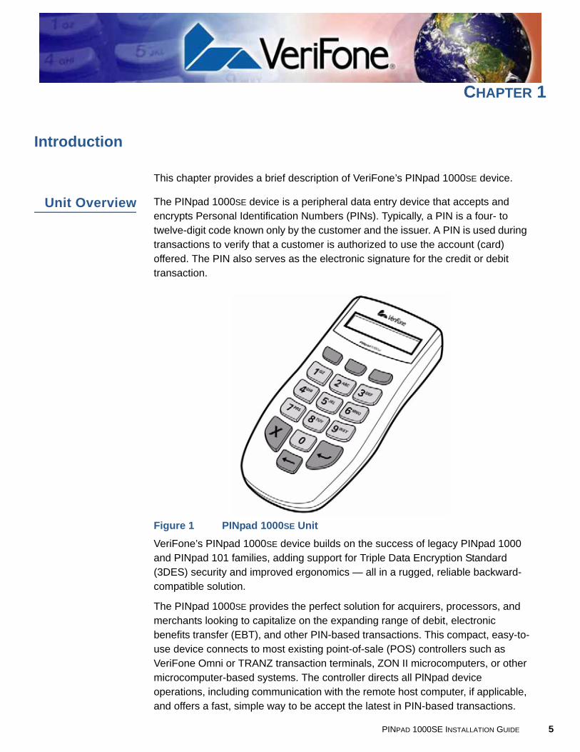
Unit Overview The PINpad 1000SE device is a peripheral data entry device that accepts and encrypts Personal Identification Numbers (PINs). Typically, a PIN is a four- to twelve-digit code known only by the customer and the issuer. A PIN is used during transactions to verify that a customer is authorized to use the account (card) offered. The PIN also serves as the electronic signature for the credit or debit transaction.
Figure 1 PINpad 1000SE UnitVeriFone’s PINpad 1000SE device builds on the success of legacy PINpad 1000 and PINpad 101 families, adding support for Triple Data Encryption Standard (3DES) security and improved ergonomics — all in a rugged, reliable backward-compatible solution.
The PINpad 1000SE provides the perfect solution for acquirers, processors, and merchants looking to capitalize on the expanding range of debit, electronic benefits transfer (EBT), and other PIN-based transactions. This compact, easy-to-use device connects to most existing point-of-sale (POS) controllers such as VeriFone Omni or TRANZ transaction terminals, ZON II microcomputers, or other microcomputer-based systems. The controller directs all PlNpad device operations, including communication with the remote host computer, if applicable, and offers a fast, simple way to be accept the latest in PIN-based transactions.
PINPAD 1000SE INSTALLATION GUIDE 5

INTRODUCTIONFeatures and Benefits
6
The PED-compliant PINpad 1000SE incorporates a broad array of sophisticated security features to guard against fraud and abuse. This includes full support for the 3DES encryption standard, and a choice of Master/Session or DUKPT (Derived Unique Key Per Transaction) key management methods. The PINpad 1000SE also supports MAC (Message Authentication Code) to protect debit transaction data from accidental or fraudulent tampering during transfer to its host.
The PINpad 1000SE features improved ergonomics with large, hard-rubber keys for ease of use, and a sleek new design that fits in the palm of a hand. The device is rugged and reliable, built to withstand the hard knocks at the point of sale. Most importantly, the PINpad 1000SE is fully compatible with the legacy PINpad 1000 and PINpad 101 families.
Features andBenefits
Exceptional Ease of Use and Ergonomics
• Sleek and stylish shape occupies less counter space than the PINpad 1000.
• Bold, ergonomic design fits comfortably in the palm of a hand and grip-zone texture on the case provides a better grip.
• Large, hard-rubber keys provide improved tactile feedback, minimizing errors and maximizing ease-of-use for consumers of all ages.
• Intuitive telco-style interface and colored control keys simplify training and reduce support requests.
• Programmable function keys allows selection of functions within an application.
• Highly readable 8-character liquid crystal display supports multiple languages for global applications and automatically scrolls through up to 16 characters.
Critical Security Protection
• Includes full support for single and 3DES encryption standard.
• Offers a choice of Master/Session or DUKPT key-management methods to protect PIN-based transactions.
• Offers secure, reliable PIN input for expanding range of PIN-based transactions.
• Is PED-compliant for secure solutions meeting the PED standard.
• Meets ISO and ANSI standards for PIN encryption, key management, and MAC.
• Incorporates tamper-detection glued case to resist unauthorized intrusion and supports a broad spectrum of software-based security features.
• Key injection simplified and secured with VeriFone’s SecureKit key loading software.
PINPAD 1000SE INSTALLATION GUIDE
INTRODUCTIONFeatures and Benefits
Strong Flexibility
• Rugged and reliable design absorbs the hard knocks found at POS.
• Removable privacy shield offers option of supplemental physical security.
• Optional key overlays allow localizing by language.
• Well-planned shape works with existing VeriFone PINpad stands and wall- or counter-mounting hardware.
• Connects with most POS payment terminals, PCs, and ECRs.
• Backward-compatible with VeriFone’s PINpad 1000 and PINpad 101 legacy families.
PINPAD 1000SE INSTALLATION GUIDE 7

INTRODUCTIONFeatures and Benefits
8
PINPAD 1000SE INSTALLATION GUIDE
CHAPTER 2
Setup
This chapter describes the setup procedure for PINpad 1000SE units, in the following sections:
• Select Location
• Unpack Shipping Carton
• Examine Unit Features
• Connect Unit to Controller
• Connect Unit to a PC/AT (optional)
• Use Stand Adapter
• Use Privacy Shield
• Use Unit
Select Location Use the following guidelines to select the best location for the PINpad 1000SE unit.
Ease of Use • Select a location convenient for both merchant and cardholder.
• Select a flat support surface, such as a countertop or table.
• Select a location near a power outlet and the terminal or computer connected to the PINpad 1000SE unit. For safety, do not string cables or cords across a walkway.
EnvironmentalFactors
• Do not use the unit where there is high heat, dust, humidity, moisture, or caustic chemicals or oils.
• Keep the unit away from direct sunlight and anything that radiates heat, such as a stove or a motor.
• Do not use the PINpad 1000SE unit outdoors.
CAUTION The PINpad 1000SE unit is not waterproof or dustproof, and is intended for indoor use only. Any damage to the unit from exposure to rain or dust can void any warranty.
PINPAD 1000SE INSTALLATION GUIDE 9
SETUPUnpack Shipping Carton
1
ElectricalConsiderations
• Avoid using this product during electrical storms.
• Avoid locations near electrical appliances or other devices that cause excessive voltage fluctuations or emit electrical noise (for example, air conditioners, electric motors, neon signs, high-frequency or magnetic security devices, or computer equipment).
• Do not use the PINpad 1000SE unit near water or in moist conditions.
UnpackShipping
Carton
Carefully inspect the shipping carton and its content for possible tampering or damage. The PINpad 1000SE device is a secure product and any tampering can cause it to cease to function or operate in an unsecured manner.
1 Remove the PINpad 1000SE unit from the shipping carton.
2 Remove any protective plastic wrap and place the unit on a table or countertop.
3 Remove the clear protective film from the display.
4 Replace all the packing materials, close the lid, and save the carton for repacking or moving the PINpad 1000SE device in the future.
WARNING Due to risk of shock or damage, do not use the PINpad 1000SE unit near water, including a bathtub, wash bowl, kitchen sink, or laundry tub, in a wet basement, or near a swimming pool.
WARNING Do not use a unit that has been tampered with or otherwise damaged.
The PINpad 1000SE unit comes equipped with tamper-evident labels. If a label or component appears damaged, immediately notify the shipping company and your VeriFone representative or service provider immediately.
0 PINPAD 1000SE INSTALLATION GUIDE
SETUPExamine Unit Features
ExamineUnit Features
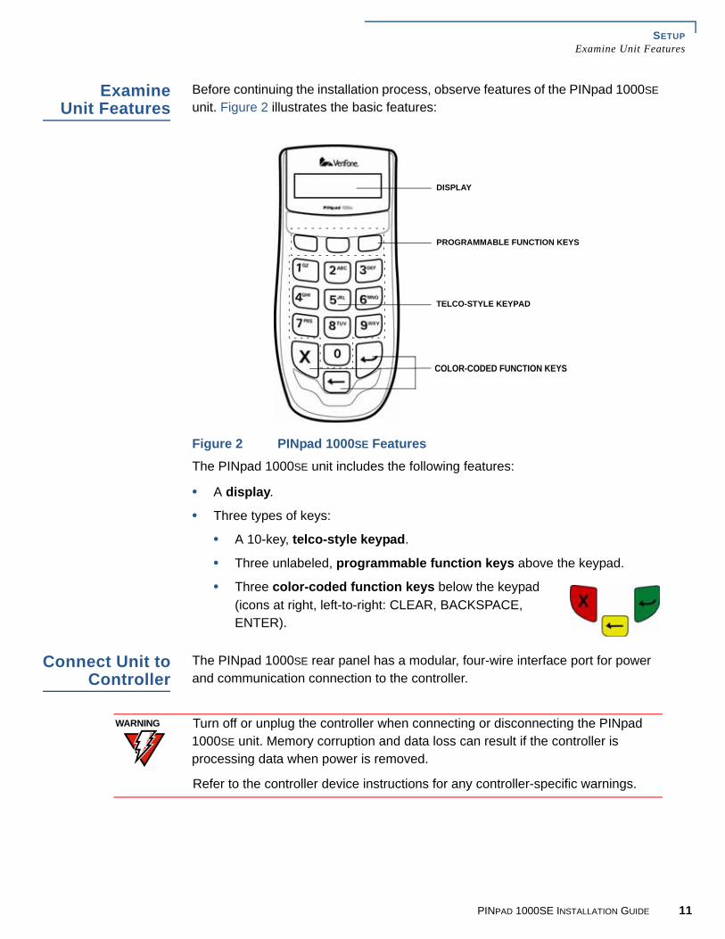
Before continuing the installation process, observe features of the PINpad 1000SE unit. Figure 2 illustrates the basic features:
Figure 2 PINpad 1000SE FeaturesThe PINpad 1000SE unit includes the following features:
• A display.
• Three types of keys:
• A 10-key, telco-style keypad.
• Three unlabeled, programmable function keys above the keypad.
• Three color-coded function keys below the keypad (icons at right, left-to-right: CLEAR, BACKSPACE, ENTER).
Connect Unit toController
The PINpad 1000SE rear panel has a modular, four-wire interface port for power and communication connection to the controller.
DISPLAY
TELCO-STYLE KEYPAD
PROGRAMMABLE FUNCTION KEYS
COLOR-CODED FUNCTION KEYS
WARNING Turn off or unplug the controller when connecting or disconnecting the PINpad 1000SE unit. Memory corruption and data loss can result if the controller is processing data when power is removed.
Refer to the controller device instructions for any controller-specific warnings.
PINPAD 1000SE INSTALLATION GUIDE 11
SETUPConnect Unit to a PC/AT (optional)
1
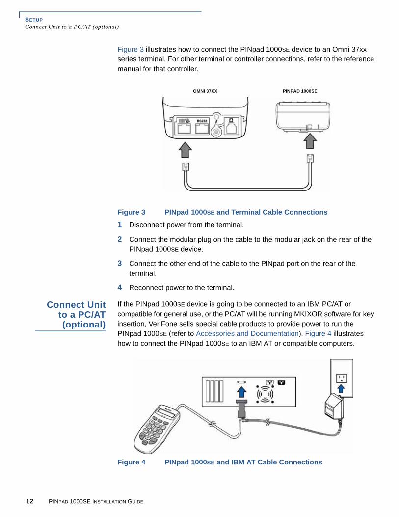
Figure 3 illustrates how to connect the PINpad 1000SE device to an Omni 37xx series terminal. For other terminal or controller connections, refer to the reference manual for that controller.
Figure 3 PINpad 1000SE and Terminal Cable Connections
1 Disconnect power from the terminal.
2 Connect the modular plug on the cable to the modular jack on the rear of the PINpad 1000SE device.
3 Connect the other end of the cable to the PlNpad port on the rear of the terminal.
4 Reconnect power to the terminal.
Connect Unitto a PC/AT(optional)
If the PINpad 1000SE device is going to be connected to an IBM PC/AT or compatible for general use, or the PC/AT will be running MKIXOR software for key insertion, VeriFone sells special cable products to provide power to run the PINpad 1000SE (refer to Accessories and Documentation). Figure 4 illustrates how to connect the PINpad 1000SE to an IBM AT or compatible computers.
Figure 4 PINpad 1000SE and IBM AT Cable Connections
OMNI 37XX PINPAD 1000SE
2 PINPAD 1000SE INSTALLATION GUIDE
SETUPUse Stand Adapter
1 Disconnect power from the PC/AT.
2 Connect the end of the cord with the DB25/DB9 connector to the PC/AT.
3 Connect the modular plug on the other end of the cord to the PINpad 1000SE device.
4 Plug the power supply cord into the socket at the base of the PC/AT connector.
5 Plug the power supply into an AC wall outlet.
6 Reconnect power to the PC/AT.
Use StandAdapter
The optional stand adapter holds the PINpad 1000SE unit securely to a countertop or a wall. The unit can be removed from the stand adapter anytime for handheld operation.
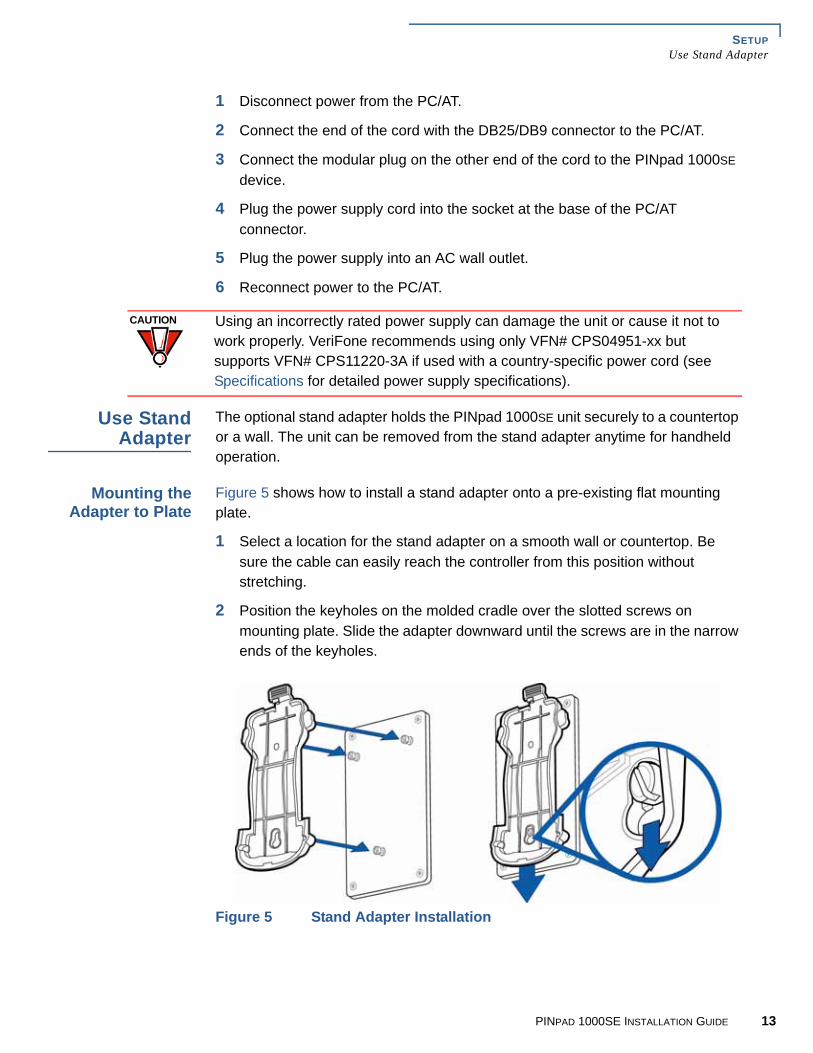
Mounting theAdapter to Plate
Figure 5 shows how to install a stand adapter onto a pre-existing flat mounting plate.
1 Select a location for the stand adapter on a smooth wall or countertop. Be sure the cable can easily reach the controller from this position without stretching.
2 Position the keyholes on the molded cradle over the slotted screws on mounting plate. Slide the adapter downward until the screws are in the narrow ends of the keyholes.
Figure 5 Stand Adapter Installation
CAUTION Using an incorrectly rated power supply can damage the unit or cause it not to work properly. VeriFone recommends using only VFN# CPS04951-xx but supports VFN# CPS11220-3A if used with a country-specific power cord (see Specifications for detailed power supply specifications).
PINPAD 1000SE INSTALLATION GUIDE 13
SETUPUse Stand Adapter
1
Screw-Mountingthe Adapter
The stand adapter may also be screwed directly to a wall or countertop.
• Use screw anchors when fastening the adapter to a cement or brick wall.
• When fastening the plate to drywall, the screws must go into the studs behind the wall. Screw anchors alone will not safely hold the adapter to drywall.
To screw-mount the stand adaptor, use American National Standard #8 or Metric M3 screws, with head diameter between 4.5 and 6.0mm, and head thickness less than 2.5mm. Use the stand adaptor to mark the hole placement on the desired location, and then insert screws, adjust the screw depth until the unit is firmly mounted.
Using the StandAdapter
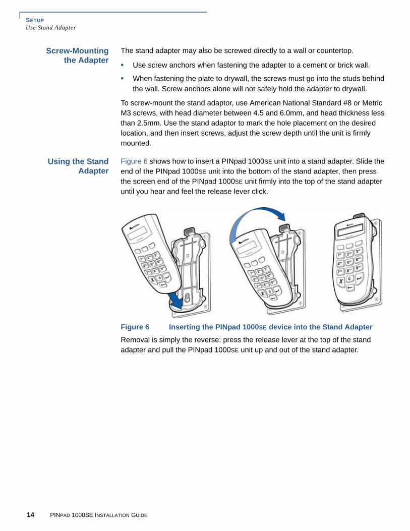
Figure 6 shows how to insert a PINpad 1000SE unit into a stand adapter. Slide the end of the PINpad 1000SE unit into the bottom of the stand adapter, then press the screen end of the PINpad 1000SE unit firmly into the top of the stand adapter until you hear and feel the release lever click.
Figure 6 Inserting the PINpad 1000SE device into the Stand AdapterRemoval is simply the reverse: press the release lever at the top of the stand adapter and pull the PINpad 1000SE unit up and out of the stand adapter.
4 PINPAD 1000SE INSTALLATION GUIDE

SETUPUse Privacy Shield
Use PrivacyShield
Figure 7 shows an example of an installed privacy shield.
Figure 7 Installed Privacy Shield
Use Unit
Startup Upon startup, the PINpad 1000SE briefly displays the version and date (example: 4E00001 1 W94) followed by the idle prompt.
Idle Prompt The idle prompt indicates the PINpad 1000SE is ready for use. The default idle prompt is a row of characters that resembles a marching arrow (<------------).
The display and sequence of the idle prompts can be programmed through an application program written for the controller. For example, the idle prompt display may be customized to rotate WELCOME and ENTER YOUR PIN messages.
Keypad The PINpad 1000SE unit has 10-key telco-style keypad that include letters A through Z and numerals 0 through 9, as well as three unlabeled, programmable function keys and three color-coded function keys (see Figure 2).
At the PIN request prompt, enter the PIN and press ENTER. The PINpad 1000SE rotates a processing display when it successfully receives the PIN entry.
NOTE Press CLEAR once to clear the last number.
Press CLEAR twice to cancel the transaction.
PINPAD 1000SE INSTALLATION GUIDE 15

SETUPUse Unit
1
6 PINPAD 1000SE INSTALLATION GUIDE
CHAPTER 3
Specifications
This chapter discusses power requirements, dimensions, and other specifications of the PINpad 1000SE unit.
Unit PowerRequirements
PINpad 1000SE unit: 6-14 V DC maximum power 36.5mA
Temperature Operating temperature: 0o to 40o C (32o to 104o F)
Humidity Relative humidity: 15% to 90%; no condensation
ExternalDimensions
• Length: 150 mm (5.90 in)
• Width: 68 mm (2.68 in)
• Depth: 37 mm (1.46 in)
Weight Unit weight: 190 gms (6.67 oz.)
Shipping weight: 330 g (.15 lb.)
The shipping weight includes: shipping carton, unit, one PINpad 1000SE Quick Installation Guide, and one PINpad 1000SE Certifications and Regulations.
PINPAD 1000SE INSTALLATION GUIDE 17

SPECIFICATIONSWeight
1
8 PINPAD 1000SE INSTALLATION GUIDE
CHAPTER 4
Service and Support
Maintenanceand Cleaning
PINpad 1000SE units have no user-serviceable parts. Unless otherwise instructed, do not, under any circumstances, attempt any service, adjustments, or repairs on this unit.
To clean the unit, periodically use a clean cloth slightly dampened with water and a drop or two of mild soap. For stubborn stains, use alcohol or an alcohol-based cleaner. For best results, use a Verifone Cleaning Kit (refer to Accessories and Documentation).
ServiceReturns
For PINpad 1000SE equipment failures that cannot be resolved by your help desk or service department, contact one of the following hotlines for product service and repair information:
• USA – VeriFone Service and Support Group, 1-800-834-9133, Monday - Friday, 8 A.M. - 7 P.M., EST
• International – Contact your VeriFone representative
Before returning PINpad 1000SE unit(s) to VeriFone, you must obtain a Merchandise Return Authorization (MRA) number. The following procedure describes how to return one or more PINpad 1000SE units for repair or replacement (U.S. customers only).
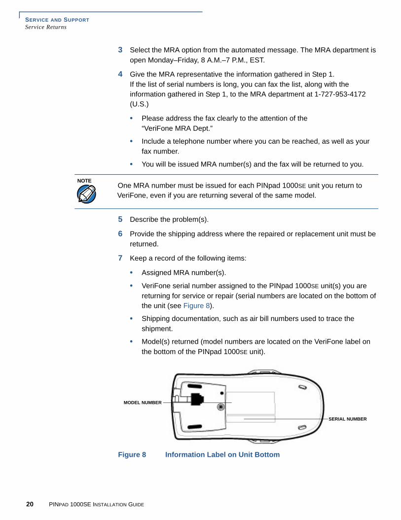
1 Gather the following information from the printed labels (see Figure 8) on the bottom of each PINpad 1000SE unit to be returned:
• Product ID, including the model and part number. For example, “P003-160-01.”
• Serial number (S/N xxx-xxx-xxx)
2 Within the United States, call VeriFone toll-free at 1-800-834-9133.
CAUTION Never use thinner, trichloroethylene, or ketone-based solvents – they can deteriorate plastic or rubber parts.
Because the PINpad 1000SE unit can be damaged by liquid, do not spray cleaners or other solutions directly onto the keypad or display. Always apply the cleaner to a cloth before cleaning the device.
NOTEInternational customers, please contact your local VeriFone representative for assistance with your service, return, or replacement.
PINPAD 1000SE INSTALLATION GUIDE 19
SERVICE AND SUPPORTService Returns
2
3 Select the MRA option from the automated message. The MRA department is open Monday–Friday, 8 A.M.–7 P.M., EST.
4 Give the MRA representative the information gathered in Step 1.If the list of serial numbers is long, you can fax the list, along with the information gathered in Step 1, to the MRA department at 1-727-953-4172 (U.S.)
• Please address the fax clearly to the attention of the“VeriFone MRA Dept.”
• Include a telephone number where you can be reached, as well as your fax number.
• You will be issued MRA number(s) and the fax will be returned to you.
5 Describe the problem(s).
6 Provide the shipping address where the repaired or replacement unit must be returned.
7 Keep a record of the following items:
• Assigned MRA number(s).
• VeriFone serial number assigned to the PINpad 1000SE unit(s) you are returning for service or repair (serial numbers are located on the bottom of the unit (see Figure 8).
• Shipping documentation, such as air bill numbers used to trace the shipment.
• Model(s) returned (model numbers are located on the VeriFone label on the bottom of the PINpad 1000SE unit).
Figure 8 Information Label on Unit Bottom
NOTEOne MRA number must be issued for each PINpad 1000SE unit you return to VeriFone, even if you are returning several of the same model.
SERIAL NUMBER
MODEL NUMBER
0 PINPAD 1000SE INSTALLATION GUIDE

SERVICE AND SUPPORTAccessories and Documentation
Accessoriesand
Documentation
VeriFone produces accessories and documentation for the PINpad 1000SE unit. When ordering, please refer to the part number in the left column.
• VeriFone Online Store at www.store.verifone.com
• USA – VeriFone Customer Development Center, 1-800-VeriFone (837-4366) Monday - Friday, 7 A.M. - 5 P.M., MST
• International – Contact your VeriFone representative
Cables Contact your local VeriFone distributor to determine which cable fits your needs.
07042-xx 4PC plug to MOD10 plug, coiled (Omni 32xx, 33xx, 36xx, or 37xx Series Terminals)
10441-xx 4PC plug to 6-pin DIN plug, coiled (most Tranz terminals)
01582-xx 4PC plug to 6-pin DIN plug, straight (most Tranz terminals)
03021-xx 4PC plug to 6-pin mini-DIN plug, coiled (Omni 4xx and 7000MPD terminals, as well as Everest and Everest Plus terminals)
Power Supply CPS04951-xx DC power supply
CPS11220-3A DC power pack (universal)
Power Cord 07152-xx United States of America
PC/AT InterfaceKits
10776-01 4PC plug to DB25 plug (most IBM PC or compatible computers)
10776-02 4PC plug to DB9 plug (most IBM AT or compatible computers)
SupplementaryHardware
E-100674051 Stand adapter
E-100675051 Privacy shield
NOTE
Cables with -xx part number suffixes have multiple available lengths.
NOTE Cables with -xx part number suffixes have multiple available versions. VeriFone supports different variants of the CPS04951-xx power supply based on the country where it will be used. Contact your local VeriFone representative or service provider to identify the best power supply for your needs.
NOTE VeriFone supports different power cords based on the country where they will be used. Contact your local VeriFone representative or service provider to identify the best power supply for your needs.
PINPAD 1000SE INSTALLATION GUIDE 21

SERVICE AND SUPPORTAccessories and Documentation
2
Cleaning Kit 02746-01 VeriFone Cleaning Kit
Documentation 22900 PINpad 1000SE Certifications and Regulations
22901 PINpad 1000SE Quick Installation Guide
22903 PINpad 1000SE Reference and Programmers Manual
22906 PINpad 1000SE Stand Adapter Quick Installation Guide
2 PINPAD 1000SE INSTALLATION GUIDE
CHAPTER 5
Troubleshooting Guidelines
This chapter lists typical malfunctions that may occur while operating a PINpad 1000SE unit and the appropriate corrective action. If the problem persists even after performing the outlined guidelines or if the problem is not described, contact your local VeriFone representative for assistance.
Display PanelDoes Not Work
1 Check all the cable connections.
2 Check the controller's AC outlet to be sure the outlet is supplying sufficient power. Substitute the controller's power pack with another power pack.
3 The controller's application program might not be loaded correctly. Download the application program and try again.
4 Run the display reliability test (option 5) as described in Section 3 in the PINpad 1000SE Reference and Programmers Manual (VPN - 22903).
5 If the problem persists, contact your local VeriFone representative.
Keypad DoesNot Respond
1 Check the display panel. If there are no characters, or the wrong characters are displayed, refer to Display Panel Does Not Work.
2 Run the keypad reliability test (Option 4) as described in Section 3 in the PINpad 1000SE Reference and Programmers Manual (VPN - 22903).
3 If the problem persists, contact your local VeriFone representative.
NOTE The PINpad 1000SE unit uses a tamper-evident case. The PINpad 1000SE unit contains no user-serviceable parts. Do not, under any circumstance, attempt to disassemble the unit. Perform only those adjustments or repairs specified in this guide. For all other services, contact your local VeriFone service provider. Service conducted by parties other than authorized VeriFone representatives may void any warranty.
PINPAD 1000SE INSTALLATION GUIDE 23

PINpad 1000SE
Installation Guide
VeriFone Part Number 22902, Revision C
VeriFone, Inc.2455 Augustine DriveSanta Clara CA 95054-3002Tel: (800) VeriFone (837-4366)www.verifone.com