pinning effect on the phase separation dynamics of thin polymer-dispersed liquid crystals
TRANSCRIPT
Pinning effect on the phase separation dynamics of thin polymer-dispersed liquid crystals
Yi-Hsin Lin, Hongwen Ren, Yung-Hsun Wu, Xiao Liang and Shin-Tson Wu College of Optics and Photonics, University of Central Florida, Orlando, Florida 32816
http://lcd.creol.ucf.edu
Abstract: The surface pining effects on phase separation dynamics of polymer-dispersed liquid crystals (PDLCs) with thin cell gaps are demonstrated. Comparing various boundary conditions, the inner surfaces of the substrates with or without polyimide layers [but no rubbing] cannot provide enough anchoring force, so in either case the liquid crystal (LC) droplets flow and coalesce to form larger and less uniform droplets. However, if the inner surfaces of the substrates are coated with rubbed polyimide layers with anchoring energy >1x10⁻⁴ J/m2, almost all the nucleated LC droplets grow at a fixed position during phase separation. The appearance of the coalescence is not obvious and the formed LC droplets are relatively uniform. The surface anchoring has a significant effect on the morphology of PDLCs.
©2005 Optical Society of America
OCIS codes: (230.3720) Liquid-crystal devices; (160.5470) Polymers
References and links
1. J. L. Fergason, US Patent 4,435,047 (1984). 2. J. W. Doane, N. A. Vaz, B. G. Wu and S. Zumer, “Field controlled light-scattering from nematic
microdroplets,” Appl. Phys. Lett. 48, 269-271 (1986). 3. N. A. Vaz, G. W. Smith, and G. P. Montgomery, “A light control film composed of liquid-crystal droplets
dispersed in a UV-curable polymer ,” Mol. Cryst. Liq. Cryst. 146, 1-15 (1987). 4. R. Sutherland, L.V. Natarajan, V.P. Tondiglia, and T. J. Bunning, “Bragg gratings in an acrylate polymer
consisting of periodic polymer-dispersed liquid-crystal planes,” Chem. Mater. 5, 1533- (1993). 5. F. Basile, F. Bloisi, L. Vicari, and F. Simoni,”Optical-phase shift of polymer-dispersed liquid-crystals,”
Phys. Rev. E 48, 432-438 (1993). 6. L. Vicari, “Electro-optic phase modulation by polymer dispersed liquid crystals,” J. Appl. Phys. 81, 6612-
6615 (1997). 7. S. Matsumoto, M. Houlbert, T. Hayashi, and K. Kubodera, “Fine droplets of liquid crystals in a transparent
polymer and their response to an electric field,” Appl. Phys. Lett, 69, 1044-1046 (1996). 8. S. X. Cheng, R. K. Bai, Y. F. Zou, and C. Y. Pan, “Electro-optical properties of polymer dispersed liquid
crystal materials” J. Appl. Phys, 80, 1991-1995 (1996). 9. H. Ren and S. T. Wu, “Inhomogeneous nanoscale polymer-dispersed liquid crystals with gradient refractive
index,” Appl. Phys. Lett. 81, 3537-3539 (2002). 10. W. J. Chen and S. H. Chen, “Addition polymerization in a nematic medium-effects of an anisotropic solvent
in a kinetic gelation model,” Phys. Rev. E 52, 4549-4552 (1995). 11. P. I. C. Teixeira and B. M. Mulder, “Cell dynamics model of droplet formation in polymer-dispersed liquid
crystals,” Phys. Rev. E 53, 1805-1815 (1996). 12. D. Nwabunma, H. Chiu, and T. Kyu, “Theoretical investigation on dynamics of photopolymerization-
induced phase separation and morphology development in nematic liquid crystal/polymer mixtures,” J. Chem. Phys 113, 6429-6436 (2000).
13. T. Kyu and H. Chiu, “Morphology development during polymerization-induced phase separation in a polymer dispersed liquid crystals,” Polymer 42, 9173-9185 (2001).
14. A. Mertelj, L. Spindler, and M. Copic, “Dynamic light scattering in polymer-dispersed liquid crystals,” Phys. Rev. E 56, 549-553 (1997).
15. J. B Nephew, T. C. Nihei, and S. A. Carter, “Reaction-induced phase separation dynamics: a polymer in a liquid crystal solvent,” Phys. Rev. Lett. 80, 3276-3279 (1998).
16. P. S. Drzaic, Liquid Crystal Dispersions (World Scientific, Singapore, 1995), Chap. 4.
(C) 2005 OSA 24 January 2005 / Vol. 13, No. 2 / OPTICS EXPRESS 468#6097 - $15.00 US Received 17 December 2004; revised 11 January 2005; accepted 11 January 2005

17. Y. H. Lin, H. Ren, and S. T. Wu, “High contrast polymer-dispersed liquid crystal in a 90 degrees twisted cell,” Appl. Phys. Lett. 84, 4083-4085 (2004).
18. H. M. J. Boot, J. G. Kloosterboer, C. Serbutoviez, and F. J. Touwslager, “Polymerization-induced phase separation .1. Conversion-phase diagrams,” Macromolecules 29, 7683-7689 (1996).
19. J. Cognard,”Alignment of nematic liquid-crystals and their mixtures,” Mol. Cryst. Liq. Cryst. Suppl. 1, 1-77 (1982).
20. H. Yokoyama and H. A. Van Sprang, “A novel method for determining the anchoring energy function at a nematic liquid crystal-wall interface from director distortions at high fields,” J. Appl. Phys. 57, 4520-4526 (1985).
21. S. T. Wu, “Birefringence dispersions of liquid crystals,” Phys. Rev. A 33, 1270-1274 (1986).
1. Introduction
Polymer dispersed liquid crystals (PDLCs), consisting of micron-sized LC droplets dispersed in a polymer matrix, are a promising electro-optic material for displays [1, 2], light switches [3-8] and tunable-focus lenses [9] because of their polarization independence. The phase separation, which is an important process affecting the electro-optic properties of PDLCs, has been studied by computer simulations [10-13] and by experiments [14, 15]. In a conventional PDLC, the formed droplets, each about the size of a visible wavelength, are randomly distributed in the polymer matrix. Typically, the LC and monomer mixture is sandwiched between two indium-tin-oxide (ITO) glasses without any surface treatments. After photo-induced phase separation, the droplets are formed and their sizes vary. Due to the relatively large cell gap and micron-sized LC droplets, phase separation dynamics do not depend on surface interaction. The phase separation dynamics determine the final composite morphology of PDLC. The more uniform LC droplets exhibit a higher light scattering efficiency and higher device contrast ratio [16, 17].
Several factors, such as the transition from isotropic to nematic ordering of the LCs, the solubility of the LC and monomer, the growing molecular weight and the gelation of polymer matrix and elastic forces in the polymer matrix [16,18], compete with each other to determine the phase separation dynamics of PDLCs. In this paper, we demonstrate that the phase separation dynamics are influenced by the surface effect for a PDLC confined in a thin cell. The PDLCs with a strong surface anchoring exhibit smaller LC droplets and better uniformity because the anchoring force in the boundaries fixes the droplets and prevents them from flowing and coalescing.
2. Sample fabrication
To fabricate a PDLC device, we mixed UV-curable monomer NOA65 in a nematic LC host (E48, ∆n= 0.231 at λ=589 nm and T=22 oC). We varied the polymer concentration from 20 to 40 wt %. However, the general phenomena remain the same except for the different droplet sizes. Thus, we focus our discussions using the PDLC with 30 wt % NOA65 as examples. The LC and monomer mixture was injected into an empty cell in the isotropic state. The cell gap is d=8 µm. For comparison, we prepared four types of cells with different surface treatments: 1) a conventional PDLC cell, i.e. the indium-tin-oxide (ITO) glass substrates without polyimide (PI) alignment layers, 2) a PI cell, i.e. an ITO glass cell with each inner surface overcoated with a thin (~10 nm) PI layer but without rubbing, 3) a 90o twisted nematic (TN) cell, i.e., the ITO glass substrates with orthogonal rubbing alignment layers, and 4) a homogeneous cell, i.e., the ITO glass substrates with anti-parallel rubbing alignment layers. The polyimide we used is PI-2525 (HD MicroSystems). A thin PI layer (~800 nm) was spin-coated on glass substrates and then baked in an oven (250oC) for about one hour. For the homogeneous and TN cells, the coated PI substrates were buffed using a rubbing machine. The polar anchoring energy of these TN and homogeneous cells was measured to be ~3x10⁻⁴ J/m2 by the voltage-dependent phase retardation method [19, 20]. The pretilt angle of these PI cells is about 3o.
3. Experiment and results
Figures 1(a) to 1(e) show the morphologies of the above mentioned conventional, PI, TN, and homogeneous UV-cured PDLC cells observed from a polarized optical microscope in the
(C) 2005 OSA 24 January 2005 / Vol. 13, No. 2 / OPTICS EXPRESS 469#6097 - $15.00 US Received 17 December 2004; revised 11 January 2005; accepted 11 January 2005
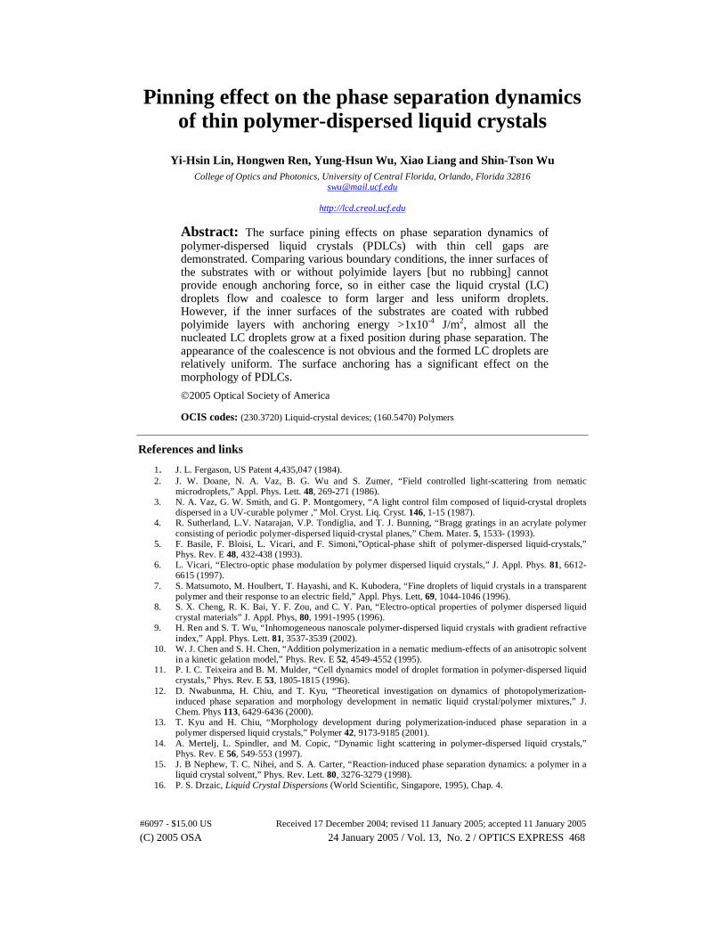
voltage-off state. The UV exposure intensity was I=60 mW/cm2 and the curing time for both cells was 15 min at T=20 oC. From Figs. 1(a) and 1(b), we find that the LC droplets in the conventional and non-rubbed PI cells are larger and less uniform than those observed in Figs. 1(c) for the TN cells and 1(d) for homogeneous cells. That means the rubbed PI surfaces have a crucial influence on the phase separation of PDLC when the cell gap is thin. The smaller and more uniform LC droplets exhibit a higher light scattering efficiency which, in turn, leads to a higher device contrast ratio. [17] For comparison, the morphology in the homogeneous cell with weaker anchoring energy ~1x10⁻⁴ J/m2 is also nonuniform as shown in Fig. 1(e).
(a) (b) (c)
(d) (e)
Fig. 1. Phase separation morphologies of PDLC in (a) conventional cell, (b) PI cell without rubbing, (c) TN cell (anchoring energy ~3x10⁻⁴ J/m2), (d) homogeneous cell (anchoring energy ~3x10⁻⁴ J/m2), and (e) homogeneous cell (anchoring energy ~1x10⁻⁴ J/m2) observed from a polarized optical microscope. LC/monomer mixture: 70 wt% E48 and 30 wt% NOA65. Both devices have the same cell gap d~8 µm.
To show that the phase separation dynamics indeed depend on the surface rubbing
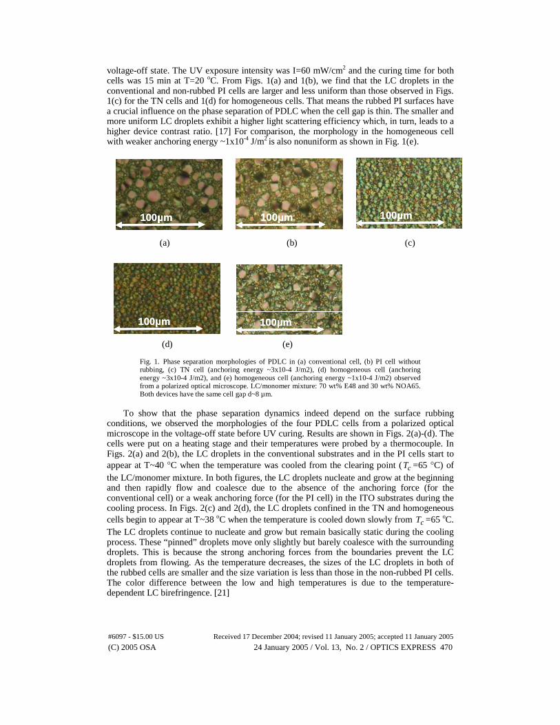
conditions, we observed the morphologies of the four PDLC cells from a polarized optical microscope in the voltage-off state before UV curing. Results are shown in Figs. 2(a)-(d). The cells were put on a heating stage and their temperatures were probed by a thermocouple. In Figs. 2(a) and 2(b), the LC droplets in the conventional substrates and in the PI cells start to appear at T~40 °C when the temperature was cooled from the clearing point ( cT =65 °C) of the LC/monomer mixture. In both figures, the LC droplets nucleate and grow at the beginning and then rapidly flow and coalesce due to the absence of the anchoring force (for the conventional cell) or a weak anchoring force (for the PI cell) in the ITO substrates during the cooling process. In Figs. 2(c) and 2(d), the LC droplets confined in the TN and homogeneous cells begin to appear at T~38 oC when the temperature is cooled down slowly from cT =65 oC. The LC droplets continue to nucleate and grow but remain basically static during the cooling process. These “pinned” droplets move only slightly but barely coalesce with the surrounding droplets. This is because the strong anchoring forces from the boundaries prevent the LC droplets from flowing. As the temperature decreases, the sizes of the LC droplets in both of the rubbed cells are smaller and the size variation is less than those in the non-rubbed PI cells. The color difference between the low and high temperatures is due to the temperature-dependent LC birefringence. [21]
100µm100µm100µm 100µm100µm100µm 100µm100µm100µm
100µm100µm100µm 100µm100µm100µm
(C) 2005 OSA 24 January 2005 / Vol. 13, No. 2 / OPTICS EXPRESS 470#6097 - $15.00 US Received 17 December 2004; revised 11 January 2005; accepted 11 January 2005
(a) (b)
(c) (d)
Fig. 2. The dynamic phase separation morphologies of PDLC observed from a polarized optical microscope under different temperatures without UV illumination: (a) conventional PDLC cell (816KB), (b) PI without rubbing (816KB), (c) TN cell (504KB), and (d) homogeneous cell (376KB).
In Figs. 3 and 4, the cells were cooled to T=27 °C and then illuminated by UV light at
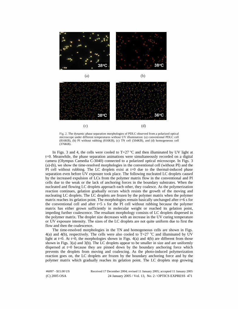
t=0. Meanwhile, the phase separation animations were simultaneously recorded on a digital camera (Olympus Camedia C-3040) connected to a polarized optical microscope. In Figs. 3 (a)-(b), we show the time-resolved morphologies in the conventional cell (without PI) and the PI cell without rubbing. The LC droplets exist at t=0 due to the thermal-induced phase separation even before UV exposure took place. The following nucleated LC droplets caused by the increased expulsion of LCs from the polymer matrix flow in the conventional and PI cells due to the weak or the lack of anchoring forces in the boundary substrates. When the nucleated and flowing LC droplets approach each other, they coalesce. As the polymerization reaction continues, gelation gradually occurs which resists the growth of the moving and nucleating LC droplets. The LC droplets are frozen by the polymer matrix when the polymer matrix reaches its gelation point. The morphologies remain basically unchanged after t=6 s for the conventional cell and after t=5 s for the PI cell without rubbing because the polymer matrix has either grown sufficiently in molecular weight or reached its gelation point, impeding further coalescence. The resultant morphology consists of LC droplets dispersed in the polymer matrix. The droplet size decreases with an increase in the UV curing temperature or UV exposure intensity. The sizes of the LC droplets are not quite uniform due to first the flow and then the coalescence.
The time-resolved morphologies in the TN and homogeneous cells are shown in Figs. 4(a) and 4(b), respectively. The cells were also cooled to T=27 oC and illuminated by UV light at t=0. At t=0, the morphologies shown in Figs. 4(a) and 4(b) are different from those shown in Figs. 3(a) and 3(b). The LC droplets appear to be smaller in size and are uniformly dispersed at t=0 because they are pinned down by the boundary anchoring force which prevents the droplets from moving and coalescing. As the photo-induced polymerization reaction goes on, the LC droplets are frozen by the boundary anchoring force and by the polymer matrix which gradually reaches its gelation point. The LC droplets stop growing
(C) 2005 OSA 24 January 2005 / Vol. 13, No. 2 / OPTICS EXPRESS 471#6097 - $15.00 US Received 17 December 2004; revised 11 January 2005; accepted 11 January 2005
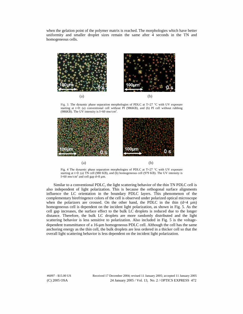
when the gelation point of the polymer matrix is reached. The morphologies which have better uniformity and smaller droplet sizes remain the same after 4 seconds in the TN and homogeneous cells.
(a) (b) Fig. 3. The dynamic phase separation morphologies of PDLC at T=27 °C with UV exposure starting at t=0: (a) conventional cell without PI (986KB), and (b) PI cell without rubbing (986KB). The UV intensity is I=60 mw/cm2.
(a) (b)
Fig. 4 The dynamic phase separation morphologies of PDLC at T=27 °C with UV exposure starting at t=0: (a) TN cell (980 KB), and (b) homogeneous cell (979 KB). The UV intensity is I=60 mw/cm2 and cell gap d=8 µm.
Similar to a conventional PDLC, the light scattering behavior of the thin TN PDLC cell is
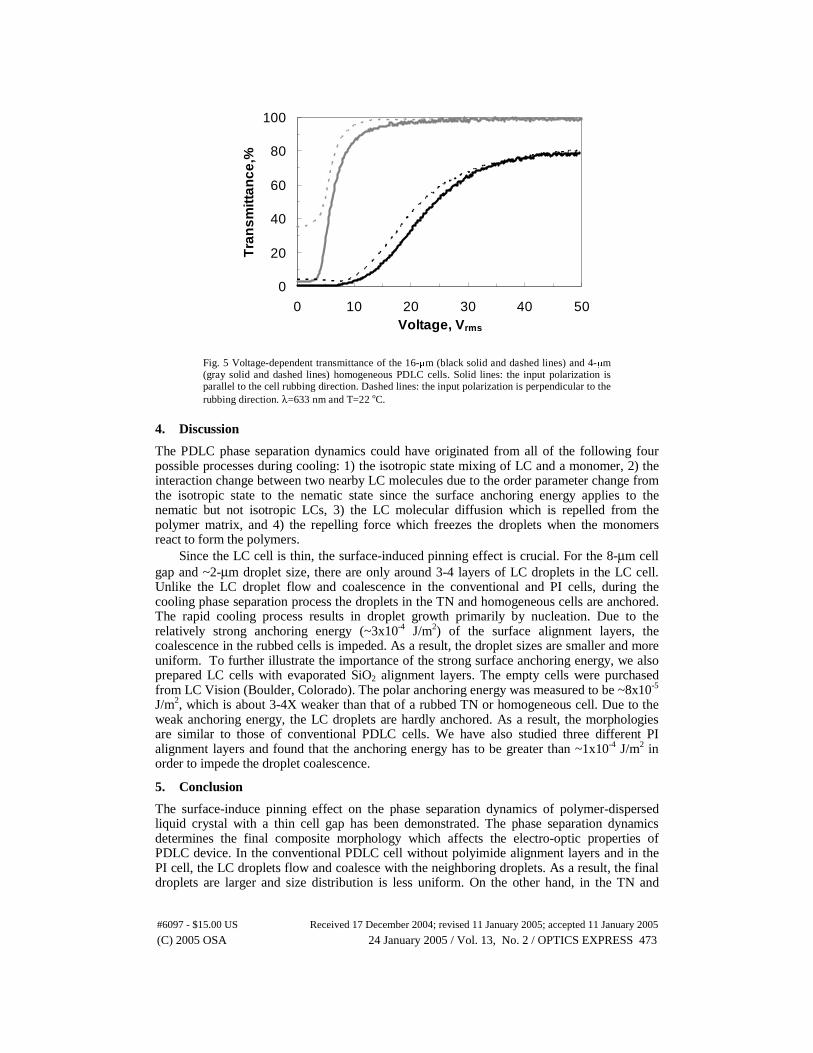
also independent of light polarization. This is because the orthogonal surface alignments influence the LC orientation in the boundary PDLC layers. This phenomenon of the complementary birefringence colors of the cell is observed under polarized optical microscope when the polarizers are crossed. On the other hand, the PDLC in the thin (d=4 µm) homogeneous cell is dependent on the incident light polarization, as shown in Fig. 5. As the cell gap increases, the surface effect to the bulk LC droplets is reduced due to the longer distance. Therefore, the bulk LC droplets are more randomly distributed and the light scattering behavior is less sensitive to polarization. Also included in Fig. 5 is the voltage-dependent transmittance of a 16-µm homogeneous PDLC cell. Although the cell has the same anchoring energy as the thin cell, the bulk droplets are less ordered in a thicker cell so that the overall light scattering behavior is less dependent on the incident light polarization.
(C) 2005 OSA 24 January 2005 / Vol. 13, No. 2 / OPTICS EXPRESS 472#6097 - $15.00 US Received 17 December 2004; revised 11 January 2005; accepted 11 January 2005
0
20
40
60
80
100
0 10 20 30 40 50Voltage, Vrms
Tra
nsm
ittan
ce,%
Fig. 5 Voltage-dependent transmittance of the 16-µm (black solid and dashed lines) and 4-µm (gray solid and dashed lines) homogeneous PDLC cells. Solid lines: the input polarization is parallel to the cell rubbing direction. Dashed lines: the input polarization is perpendicular to the rubbing direction. λ=633 nm and T=22 oC.
4. Discussion
The PDLC phase separation dynamics could have originated from all of the following four possible processes during cooling: 1) the isotropic state mixing of LC and a monomer, 2) the interaction change between two nearby LC molecules due to the order parameter change from the isotropic state to the nematic state since the surface anchoring energy applies to the nematic but not isotropic LCs, 3) the LC molecular diffusion which is repelled from the polymer matrix, and 4) the repelling force which freezes the droplets when the monomers react to form the polymers.
Since the LC cell is thin, the surface-induced pinning effect is crucial. For the 8-µm cell gap and ~2-µm droplet size, there are only around 3-4 layers of LC droplets in the LC cell. Unlike the LC droplet flow and coalescence in the conventional and PI cells, during the cooling phase separation process the droplets in the TN and homogeneous cells are anchored. The rapid cooling process results in droplet growth primarily by nucleation. Due to the relatively strong anchoring energy (~3x10⁻⁴ J/m2) of the surface alignment layers, the coalescence in the rubbed cells is impeded. As a result, the droplet sizes are smaller and more uniform. To further illustrate the importance of the strong surface anchoring energy, we also prepared LC cells with evaporated SiO2 alignment layers. The empty cells were purchased from LC Vision (Boulder, Colorado). The polar anchoring energy was measured to be ~8x10⁻⁵ J/m2, which is about 3-4X weaker than that of a rubbed TN or homogeneous cell. Due to the weak anchoring energy, the LC droplets are hardly anchored. As a result, the morphologies are similar to those of conventional PDLC cells. We have also studied three different PI alignment layers and found that the anchoring energy has to be greater than ~1x10⁻⁴ J/m2 in order to impede the droplet coalescence.
5. Conclusion
The surface-induce pinning effect on the phase separation dynamics of polymer-dispersed liquid crystal with a thin cell gap has been demonstrated. The phase separation dynamics determines the final composite morphology which affects the electro-optic properties of PDLC device. In the conventional PDLC cell without polyimide alignment layers and in the PI cell, the LC droplets flow and coalesce with the neighboring droplets. As a result, the final droplets are larger and size distribution is less uniform. On the other hand, in the TN and
(C) 2005 OSA 24 January 2005 / Vol. 13, No. 2 / OPTICS EXPRESS 473#6097 - $15.00 US Received 17 December 2004; revised 11 January 2005; accepted 11 January 2005
homogeneous cells, the LC droplets are pinned by the strong anchoring force exerted from the surface alignment layers which fix the LC droplets and hinder the coalescence during phase separation. The final morphology in these rubbed cells is much uniform and has smaller droplets.
Acknowledgments
The authors are indebted to Janet Wu and Karen Tinsley-Kim for proofreading the manuscript. This work is supported by DARPA Bio-Optic Synthetic Systems program under Contract No. W911NF04C0048.
(C) 2005 OSA 24 January 2005 / Vol. 13, No. 2 / OPTICS EXPRESS 474#6097 - $15.00 US Received 17 December 2004; revised 11 January 2005; accepted 11 January 2005