pid based dc drive
DESCRIPTION
A detail presentation PID proportional integral derivative implementation of DC drive algorithmTRANSCRIPT
PID BASED DC DRIVE USING
MICROCONTROLLER
ABDUL HASEEB SIDDIQI EE-42UMAIR JAMAL MANSURI EE-47
SYED ZOHAIB ALAM EE-56www.hasboo.co.nr
Hasboo86[at]gmail.com
1

INTRODUCTION
2

ELECTRIC DRIVEElectric drive for motor is used to draw electrical energy from
the mains and supply the electrical energy to the motor at whatever voltage, current and frequency necessary to
achieve the desired mechanical output.
3
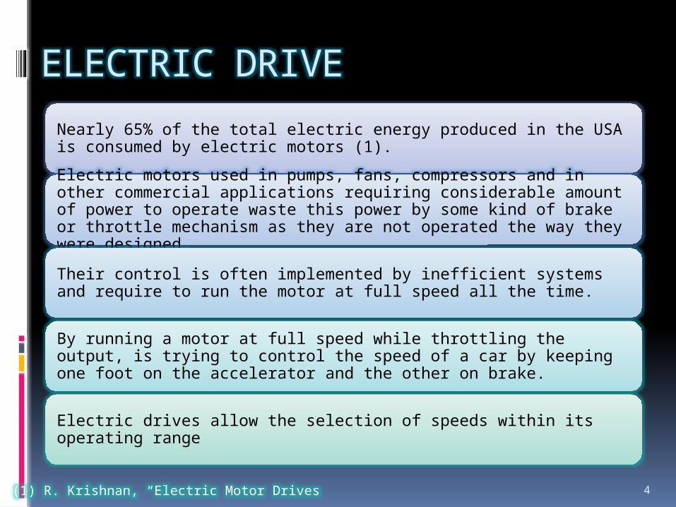
ELECTRIC DRIVENearly 65% of the total electric energy produced in the USA is consumed by electric motors (1).
Electric motors used in pumps, fans, compressors and in other commercial applications requiring considerable amount of power to operate waste this power by some kind of brake or throttle mechanism as they are not operated the way they were designed.
Their control is often implemented by inefficient systems and require to run the motor at full speed all the time.
By running a motor at full speed while throttling the output, is trying to control the speed of a car by keeping one foot on the accelerator and the other on brake.
Electric drives allow the selection of speeds within its operating range
(1) R. Krishnan, “Electric Motor Drives 4
Types
DC drives AC drives
5
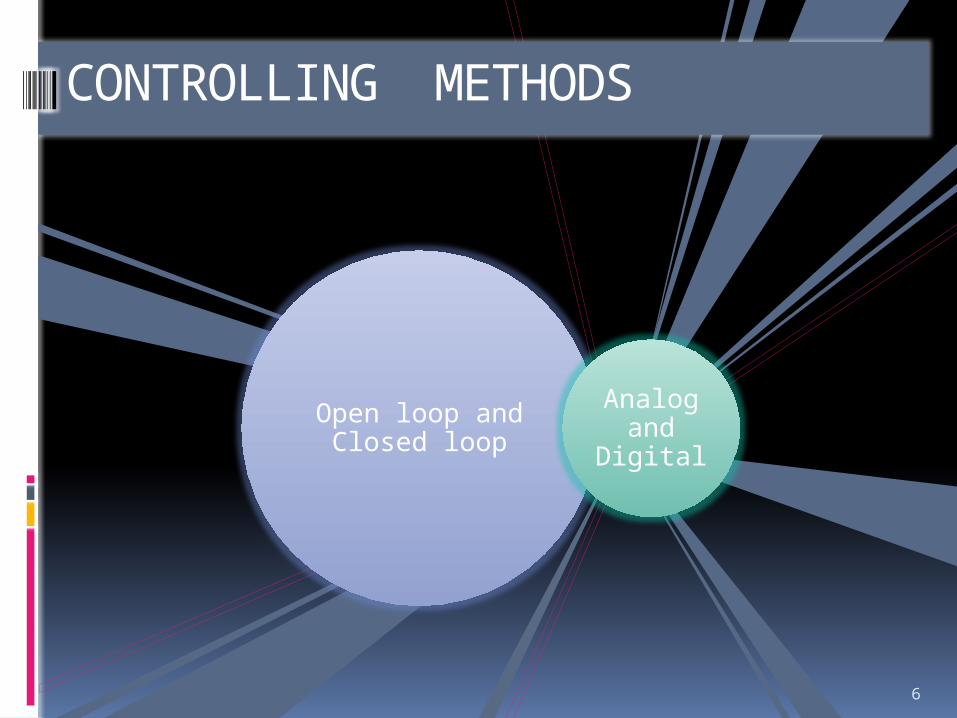
Open loop and Closed loop
Analog and
Digital
CONTROLLING METHODS
6
PROPORTIONAL , INTEGRAL & DERIVATIVE CONTROLLER
7
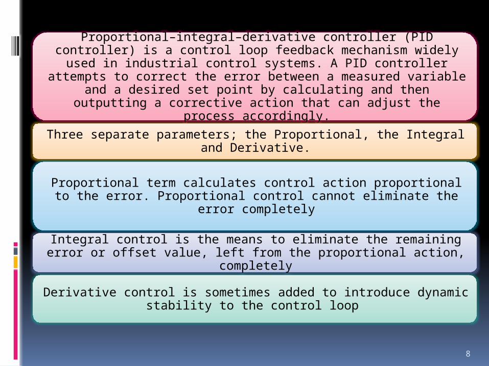
Proportional–integral–derivative controller (PID controller) is a control loop feedback mechanism widely used in industrial control systems. A PID controller attempts to correct the error between a measured variable and a desired set point by calculating and then
outputting a corrective action that can adjust the process accordingly.
Three separate parameters; the Proportional, the Integral and Derivative.
Proportional term calculates control action proportional to the error. Proportional control cannot eliminate the error completely
Integral control is the means to eliminate the remaining error or offset value, left from the proportional action, completely
Derivative control is sometimes added to introduce dynamic stability to the control loop
8
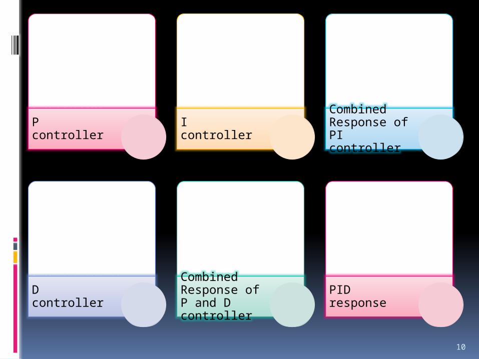
• Starting Response
• Steady State• Changing
Loads• Varying
Proportional gainP controller
• Starting Response
• Steady State• Changing
Loads• Varying gainI controller
• Varying Loads• Varying gain
Combined Response of PI controller
• Starting Response
• Steady State• Changing
Loads• Varying D gainD controller
• Varying Loads• Varying gain
Combined Response of P and D controller
• Varying Loads• Varying gain
PID response
10

DC DRIVE
11
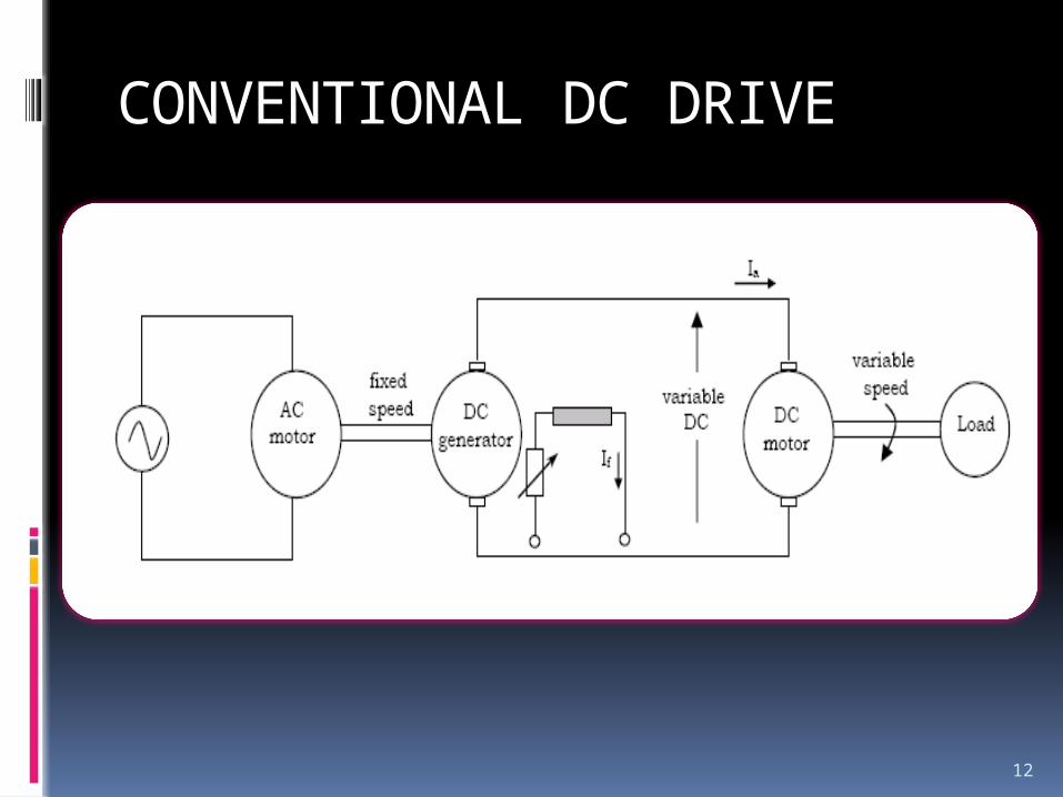
CONVENTIONAL DC DRIVE
12
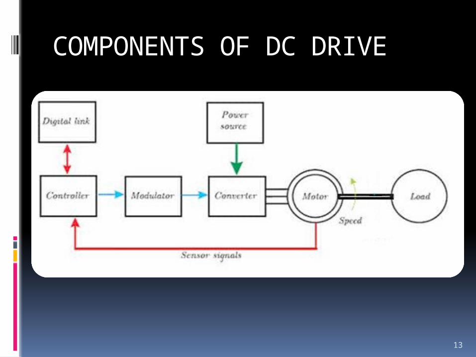
COMPONENTS OF DC DRIVE
13
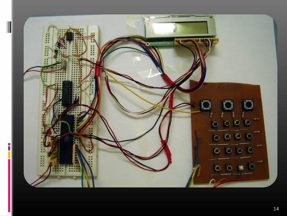
14

CONTROLLER
15
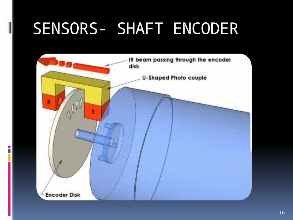
SENSORS- SHAFT ENCODER
16
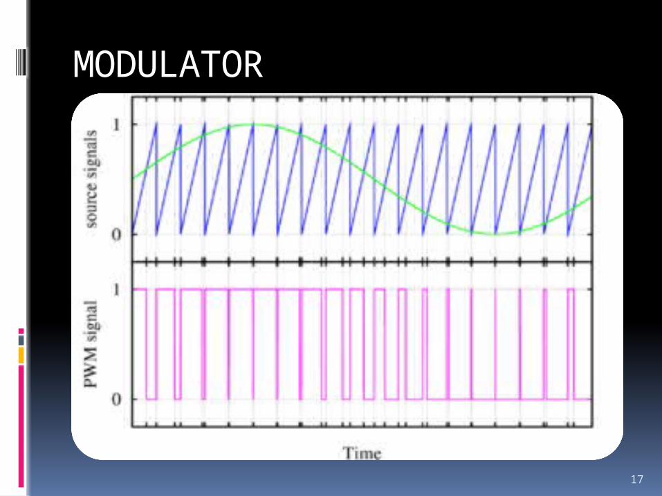
MODULATOR
17
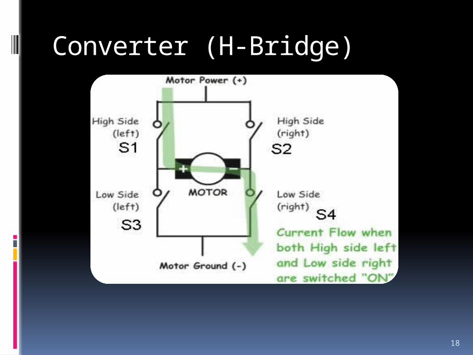
Converter (H-Bridge)
18
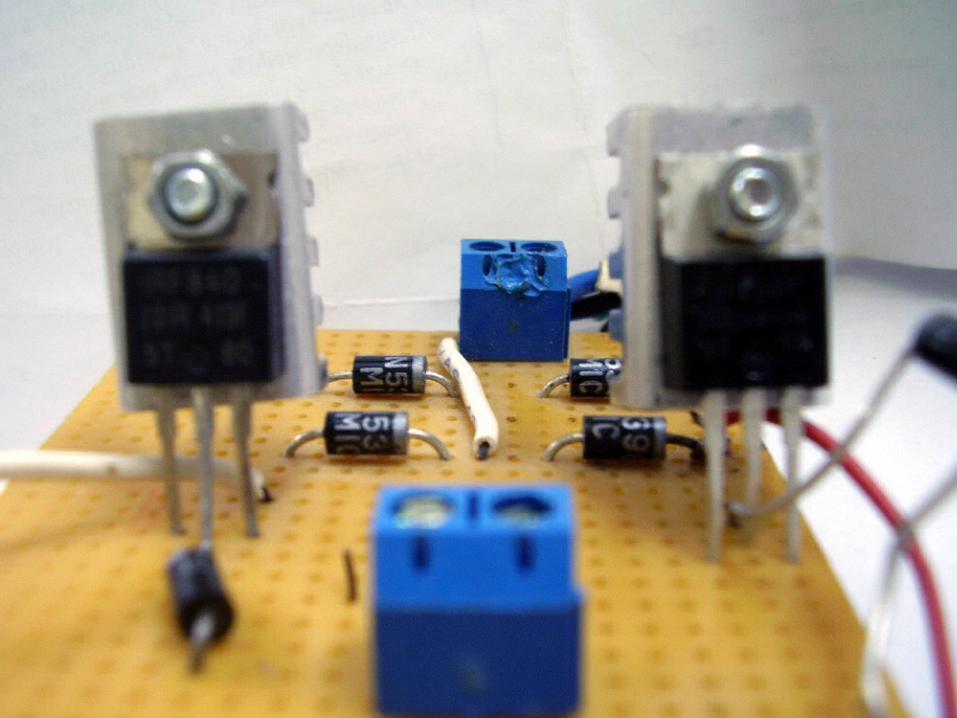
Source
19
20
FLOW DIAGRAM
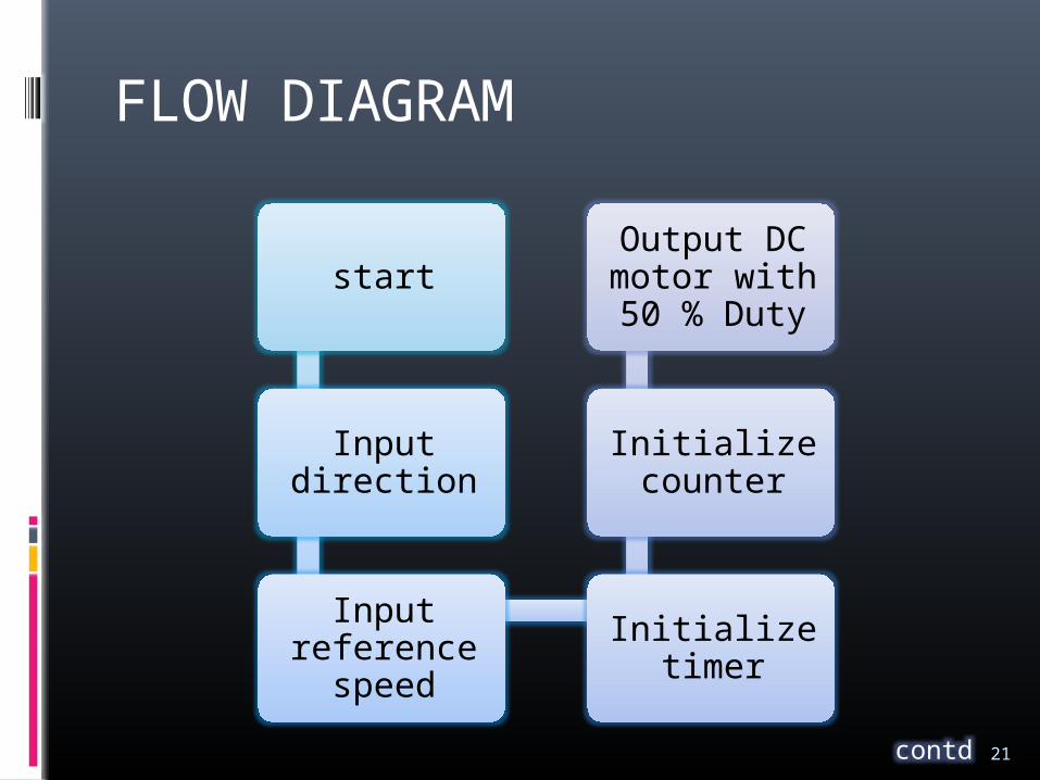
FLOW DIAGRAM
start
Input direction
Input reference
speedInitialize
timer
Initialize counter
Output DC motor with 50 % Duty
contd 21

After 30 seconds
interrupt is generated by
timer
Pulses of counter are
counted
Error = reference –
counted pulses
Sets the carry bit and PID acts
on error
Output = reference
signal +- PID answer
Output send to DAC
22

ENHANCEMENTS
23
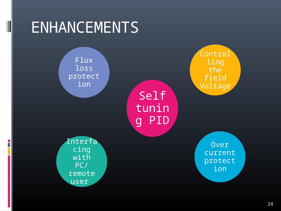
ENHANCEMENTS
Self tuning PID
Controlling the field
Voltage
Over current
protection
Flux loss protectio
n
Interfacing with
PC/ remote user
24

SIMULATION
25
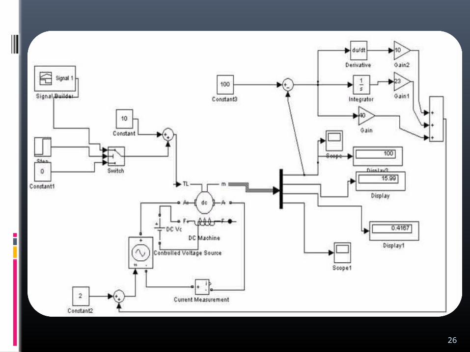
26

SPECIFICATIONS
27
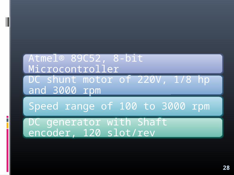
Atmel® 89C52, 8-bit MicrocontrollerDC shunt motor of 220V, 1/8 hp and 3000 rpm Speed range of 100 to 3000 rpmDC generator with Shaft encoder, 120 slot/rev
28

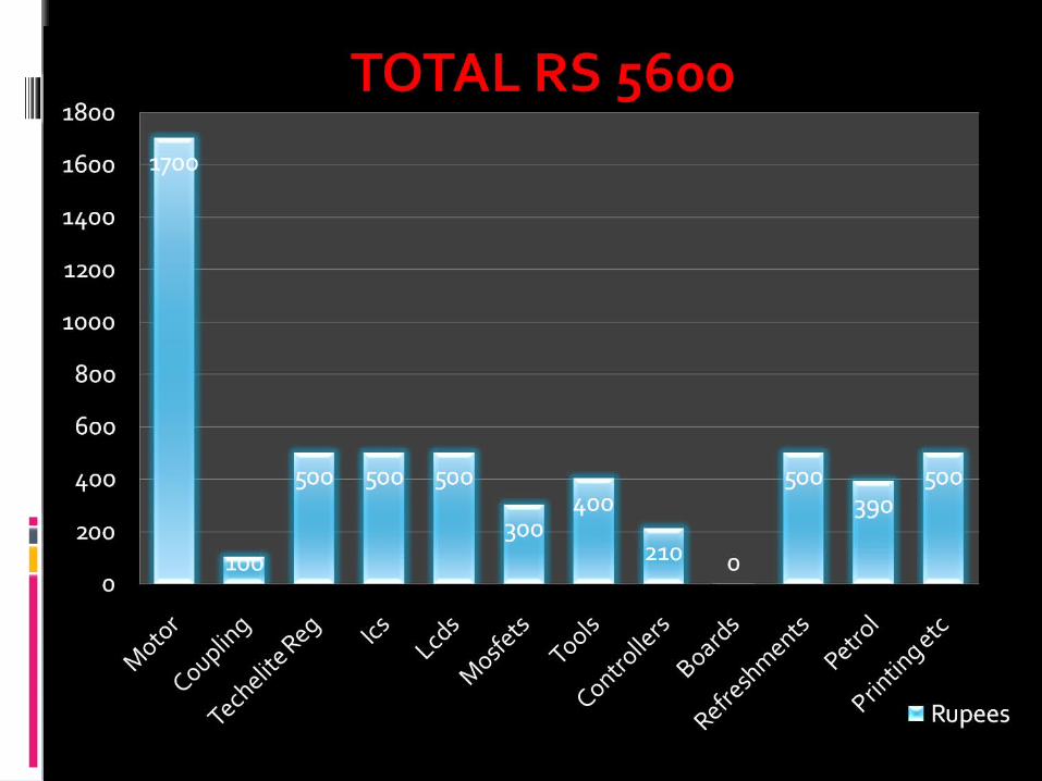
COSTS
29
30

31
THANKYOU