picture compression in fpga -...
TRANSCRIPT

Picture compression in FPGA
Per Arne Rønning
December 20, 2015
i

Abstract
This is a report for TFE4520. In this report there will be taken a closerlook on the possibility of picture compression and quality estimation ofthe picture on an FPGA. The FPGA will be programmed using VHDL.The picture compression unit is a part of the NTNU test satellite (NUTS)and there is therefore also taken into account the problems that mightarise in a space environment, and what constraints the design has.
ii

Contents
1 Introduction 11.1 Previous work . . . . . . . . . . . . . . . . . . . . . . . . . . . . . 11.2 Requirements . . . . . . . . . . . . . . . . . . . . . . . . . . . . . 1
2 Theory 32.1 Luminance . . . . . . . . . . . . . . . . . . . . . . . . . . . . . . 32.2 Chrominance . . . . . . . . . . . . . . . . . . . . . . . . . . . . . 32.3 Compression algorithm . . . . . . . . . . . . . . . . . . . . . . . . 3
2.3.1 Lossless compression . . . . . . . . . . . . . . . . . . . . . 32.3.2 Lossy compression . . . . . . . . . . . . . . . . . . . . . . 32.3.3 Wavelet compression . . . . . . . . . . . . . . . . . . . . . 3
2.4 JPEG2000 . . . . . . . . . . . . . . . . . . . . . . . . . . . . . . . 42.5 JPEG-LS . . . . . . . . . . . . . . . . . . . . . . . . . . . . . . . 42.6 Gamma correction . . . . . . . . . . . . . . . . . . . . . . . . . . 42.7 Histogram . . . . . . . . . . . . . . . . . . . . . . . . . . . . . . . 52.8 Min-Max computation . . . . . . . . . . . . . . . . . . . . . . . . 52.9 Color transform . . . . . . . . . . . . . . . . . . . . . . . . . . . . 52.10 Sign extension . . . . . . . . . . . . . . . . . . . . . . . . . . . . 5
3 Method 63.1 System overview . . . . . . . . . . . . . . . . . . . . . . . . . . . 63.2 Color transform . . . . . . . . . . . . . . . . . . . . . . . . . . . . 73.3 Histogram computation . . . . . . . . . . . . . . . . . . . . . . . 73.4 Min-Max computation . . . . . . . . . . . . . . . . . . . . . . . . 83.5 Auto exclusion . . . . . . . . . . . . . . . . . . . . . . . . . . . . 93.6 In flight reprogramming . . . . . . . . . . . . . . . . . . . . . . . 93.7 Exposure time . . . . . . . . . . . . . . . . . . . . . . . . . . . . 103.8 Data format . . . . . . . . . . . . . . . . . . . . . . . . . . . . . . 113.9 Gamma correction . . . . . . . . . . . . . . . . . . . . . . . . . . 12
4 Results 134.1 Design implementation . . . . . . . . . . . . . . . . . . . . . . . . 134.2 Min max computation . . . . . . . . . . . . . . . . . . . . . . . . 134.3 Gamma correction . . . . . . . . . . . . . . . . . . . . . . . . . . 13
5 Discussion 155.1 JPEG2000 vs JPEG-LS . . . . . . . . . . . . . . . . . . . . . . . 155.2 SD-card . . . . . . . . . . . . . . . . . . . . . . . . . . . . . . . . 155.3 In flight reprogramming . . . . . . . . . . . . . . . . . . . . . . . 165.4 Future work . . . . . . . . . . . . . . . . . . . . . . . . . . . . . . 16
6 Conclusion 17
iii

List of Figures
1 Schematic of the camera module . . . . . . . . . . . . . . . . . . 62 Flowchart for the histogram computation logic . . . . . . . . . . 83 Flowchart of the logic for min-max computation . . . . . . . . . 94 Flowchart for the auto exclude logic . . . . . . . . . . . . . . . . 105 The image sensor setup for the pixels (source: [4]) . . . . . . . . 116 The data stream from the image sensor (source: [4]) . . . . . . . 12
iv
1 Introduction
This report is written with the NUTS (NTNU test satellite) in mind. Whentaking a picture, the RAW image takes a lot of digital space. From the satelliteto earth there is limited time to send the data, and the data rate is not high.Therefore we need to compress the images down to a more manageable size, sowe can take pictures with a good resolution, and still be able to send them downto Earth. To do this we will be using an FPGA to minimize the time used, andminimize the need for memory.
Image compression usually looks at both compression, and reconstruction ofthe picture in the same system. In this case, it is just the compression thatis taking place in the FPGA, and the reconstruction will be happening on acomputer.
In addition to compressing the image, it should be able to see if the picture thatwas taken is of earth, and not just the emptiness of space, or directly at thesun.
1.1 Previous work
This work is based on the work done by Andreas Bertheusen[1] and ThomasHanssen Nornes[3], who worked on this system last year. There already existsan implementation of a functioning image compression software, but this im-plementation is, as stated, in software. There is a wish to do this in hardwareinstead, with the help of an FPGA.
1.2 Requirements
The camera module has, as the whole satellite, a set of requirements for its finaldesign
1
ID SpecificationR04-CAM-COM-001 COM = Internal Communication Bus
Must be able to communicate with the other sub systems usingthe back plane
R04-CAM-COM-002 Must be able to capture image on requestR04-CAM-COM-003 Must be able to send images to the OBC on requestR04-CAM-COM-004 Must be able to change image sensor parameters on requestR04-CAM-CPR-001 CPR = Compression of images
Must to be able to read images from the image sensor and com-press them to reduce file size
R04-CAM-CPR-002 Must be able to produce thumbnailsR04-CAM-CPR-003 Must be able to produce histograms of pixel valuesR04-CAM-CPR-004 Must be able to detect and not process unwanted images (Pictures
of space or the sun)R04-CAM-CPR-005 Must be able to make gamma corrections on captured imagesR04-CAM-IMG-001 IMG = Storing of images
Must be able to store compressed images to local memoryR04-CAM-IMG-002 Must be able to retrieve images from local memoryR04-CAM-REP-001 REP = Reprogramming
The compression logic should be able to be reprogrammed in flight
2

2 Theory
2.1 Luminance
Luminance is the brightness of a pixel. This is the only value that is necessaryto have a black and white picture.
2.2 Chrominance
Chrominance is the value that explains the colors of the image. The chromianceis usually represented by the difference between the color and the brightness ofthe pixel, where the brightness is represented by the luminance.
2.3 Compression algorithm
A compression algorithm is a method of making a file smaller. This can be donein several ways, but there are two very important versions: Lossless and lossy.The difference between these two algorithms is whether or not data is lost inthe compression process.
2.3.1 Lossless compression
In lossless compression, no data is lost. This is done by storing the data in asmarter way than the uncompressed data is.
2.3.2 Lossy compression
Lossy compression loses data in the compression process, but will get a highercompression rate than lossless compression. In image compression, much of thelost data is irrelevant for the viewer.
2.3.3 Wavelet compression
Wavelet compression is a way of compressing images and film. It compressesimages by looking at transients and takes a wavelet transfer of this. This resultsin less information needed to represent this transient on the image. So in prac-tice, what you do is to look for changes in values that are great. Because theseare the transients. This process is done several times over for a better and morecompressed image, without loosing information. This results in an image thathas degrees of resolution according to the amount of data you send. The firstdata will be a low resolution image, with the later data improving the qualityof the image by giving the higher frequency data.
3
Two dimensional discrete wavelet transfer The two dimensional DWTis made up from simple one dimensional building blocks, which converts a finitelength input sequence, x[n] into two sub band sequences y0[n] and y1[n]. Thesetwo sub bands can be seen as a low pass and high pass sub band respectivelywho have then been sub-sampled by disregarding every second sample[5, page423]. One can then look at y[2n] = y0[n] and y[2n+1] = y1[n].
Both x[n] and y[n] will have the same amount of samples. y1[n] and y0[n] willthen be half the length of x[n], and will be equal to each other as long as x[n] isan even length.
2D DWT To do a D level two dimensional discrete wavelet transfer, is to do atwo dimensional DWT of the already transferred. One does this again with thenow two timed transferred. This will be done over and over again, dependingon the size of D.[5, page 428-430]
2.4 JPEG2000
JPEG2000 is an image format that can be both lossless and lossy. JPEG2000uses wavelet compression, witch makes it possible for it to store data, and extractdifferent resolution pictures from it.
2.5 JPEG-LS
JPEG-LS stands for JPEG lossless, and is a lossless standard for compressionof images.
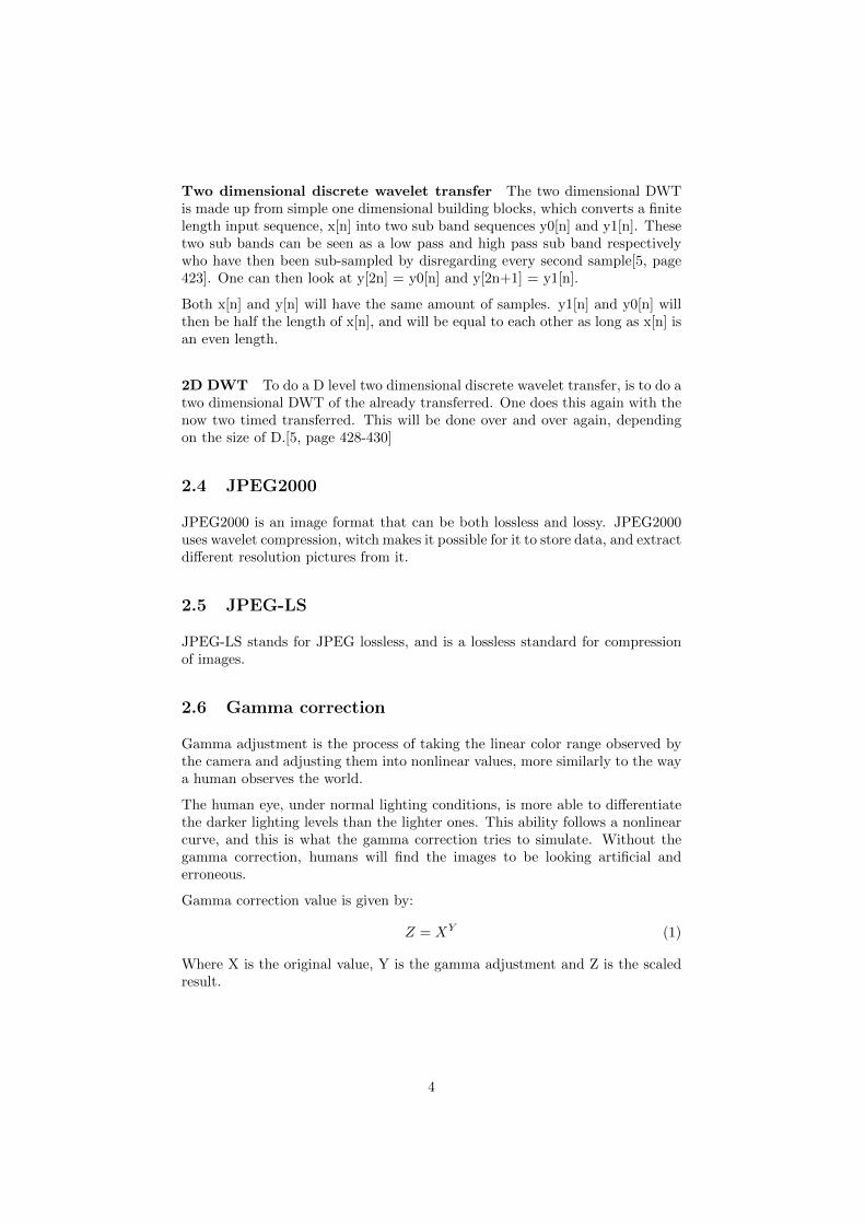
2.6 Gamma correction
Gamma adjustment is the process of taking the linear color range observed bythe camera and adjusting them into nonlinear values, more similarly to the waya human observes the world.
The human eye, under normal lighting conditions, is more able to differentiatethe darker lighting levels than the lighter ones. This ability follows a nonlinearcurve, and this is what the gamma correction tries to simulate. Without thegamma correction, humans will find the images to be looking artificial anderroneous.
Gamma correction value is given by:
Z = XY (1)
Where X is the original value, Y is the gamma adjustment and Z is the scaledresult.
4

2.7 Histogram
The computation of a histogram, is to put individual pixel values into differentpredetermined bins. This can be done both before or after the gamma correc-tion.
2.8 Min-Max computation
Min-Max computation is, as the name suggests, finding the lowest and highestvalues of the pixels from the image capture.
2.9 Color transform
Color transform comes in two different forms, irreversible and reversible colortransform. The color transform requires that the R,G and B are of the samebit-depth and dimensions.[5, page 420]
γCbCr
=
0.299 0.587 0.114−0.16875 −0.33126 0.500
0.500 −041869 −0.08131
RGB
(2)
γ =
[R+ 2G+B
4
], Db = B −G,Dr = R−G (3)
Equation 2 is the equation for the irreversible color transform, while 3 is for thereversible color transform.
2.10 Sign extension
Sign extension is to extend the size of a variable. A way to do this is to pad oneof the edges with zeros. The easiest way is to put them in the most significant bitposition, as to retain the original value, as long as it is not a signed variable orfloating point. For example will a 12 bit variable with this value: 111100001111become 0000111100001111.
5

3 Method
3.1 System overview
Figure 1: Schematic of the camera module
If we look at the schematic we can see that the micro controller is the only partof the system that communicates with the rest of the satellite, and it does thisover the CAN-bus network. The micro controller controls what happens, andwill start image capturing or image transfers upon request from the on boardcomputer.
The FPGA will handle the image compression, and handles the data directlyfrom the image sensor. The FPGA and the image sensor will be unpowered whennot in use. This is to save power. The FPGA will also have a auto-exclusionlogic, so that it can automatically exclude images that are bad. This is mainlyif the camera has been pointing towards space instead of earth at the moment ofimage capturing. The other possibility is if it is pointed towards the sun. Thisauto exclusion will be able to be turned off, in the case we want to take picturesof space, the moon, or the sun. Or if the auto exclusion seems to exclude thingstoo easy. The auto exclusion should also be able to be calibrated in flight bysetting values over the I/O pins to the micro controller. This calibration shouldbe able to change the values where it decides if the image compression shouldbe aborted or not.
One can see that from the micro controller there is an enable line that goes toa power sequencer. This is what starts up the FPGA, witch in turn starts upthe image sensor. These power sequencers are what is holding the FPGA andimage sensor in an unpowered state when image taking and compression are notactive.
The flash memory on the schematic is where the image are to be stored. This
6

must be a form of non-volatile memory as the images must not be lost in thecase of a power outage.
The USB Uart and USB FIFO are there for testing purposes in the lab, andshould not be populated on the flight model.
3.2 Color transform
Color transform is the first step in compressing the image to JPEG2000, andthe goal with this transform is to get rid of redundant information. The mostcommon form of color transformation is YCbCr transform where Y has theluminance, and Cb and Cr have the chrominance.
JPEG2000 can use two different forms of color transfers, irreversible color trans-fer or reversible color transfer. The reversible color transfer is better for our taskbecause it does not use floating point computations. The problem though, isthat it is designed for RGB, instead of RGGB which our image sensor provides.This problem can be overcomed by just simply ignoring G1 or G0, and therebyhaving a normal RGB setup, or we could do as suggested [1][page 13] by stor-ing the difference between G0 and G1 in a fourth channel, and thereby get animprovement in image quality.
3.3 Histogram computation
The histogram can be realized in two different ways. One can either have threehistograms, one for each color, or one can have a single histogram based onthe complete combined pixel value. It is suggested that the best choice is tocompute three histograms[1, page 12] for the ease of seeing the individual colordistribution. It is also suggested to only look at one of the two green values, asthese two should be almost identical.
The size of the histogram buckets will be adjustable and will therefore givedifferent value of information of the image, depending on the granularity of thehistogram.
The histogram will be the basis for the auto exclusion logic, and will be animportant tool for analyzing whether an image should be sent down to earth ornot. From the histogram we can easily see if there is an abundance of a colorin the picture, and from it, determine if it has any value for download.
The histogram will be computed directly from the image sensor stream, afterthe sign extension. This means that it will not slow the compression time down,as it will be doing its computations in parallel with the compression.
Since each color is 12 bits this gives us 4096 numbers of different values it cantake. It is suggested to have 64 bins[1, page 12]. There is also no need to havethe counter for each of the bins, to go to the maximum possibility of hits there.The interesting thing with the histogram is the correlation between the bins,not the exact number of each bin.
7

Figure 2: Flowchart for the histogram computation logic
With 64 bins, it is easy to find what bin a pixel value holds, as 4096 is thesquare of 64. Dividing the incoming pixel value by 64 will yield the bin number.After we now what bin it belongs to, we can increase the counter that showshow many hits this bin has had.
3.4 Min-Max computation
Min-Max computation is done in the FPGA, directly on the stream from theimage sensor, but after the sign extension. The operation in itself is not veryadvanced, but you get metrics that can be used later to see if the image hasbeen over or under exposed.
As seen in figure 3 the incoming data is checked to see if it is the largest orsmallest pixel value yet. If so, it is stored as the new min or max value.
8

Figure 3: Flowchart of the logic for min-max computation
The min-max computation could be computed at the same time as the his-togram computation, but it is beneficial to do either the min max computationor the histogram before the gamma correction. It is suggested that the minmax computation is done before the gamma correction, so that we can see thedynamic range of the sensor[1], and then have the histogram computed afterthe gamma correction.
The min max computation will yield the maximum and minimum values of thedifferent colors. We will therefore have eight different values.
3.5 Auto exclusion
This system will automatically decide if an image is good enough to warrant acompression. If the auto exclude logic finds the image to be too dark or bright,meaning it is pointing towards space or the sun, it will abort the compressionprocess and give a message to the micro controller.
3.6 In flight reprogramming
The FPGA has to load a bit-file every time it is powered up to know how it issupposed to work. It usually does this from the SRAM, but this is too small forthe program, and a bootloader is required.[1, page 19] This means that the bit-file has to be stored on an external memory for the FPGA to work as intended.This opens the possibility for in flight reprogramming. By allowing the MCU aconnection to the program memory, and giving it writing privileges. One cansend up a new bit file from earth, and write it to the program memory.
A possibility is to have the bit-file in the flash memory where the pictures arebeing stored. This will not require additional infrastructure or components, andboth FPGA and MCU already have connections to it. If this is done, there mustbe a reserved space of the flash memory for the bit-file, so that it will not beoverwritten when storing images or other data.
9
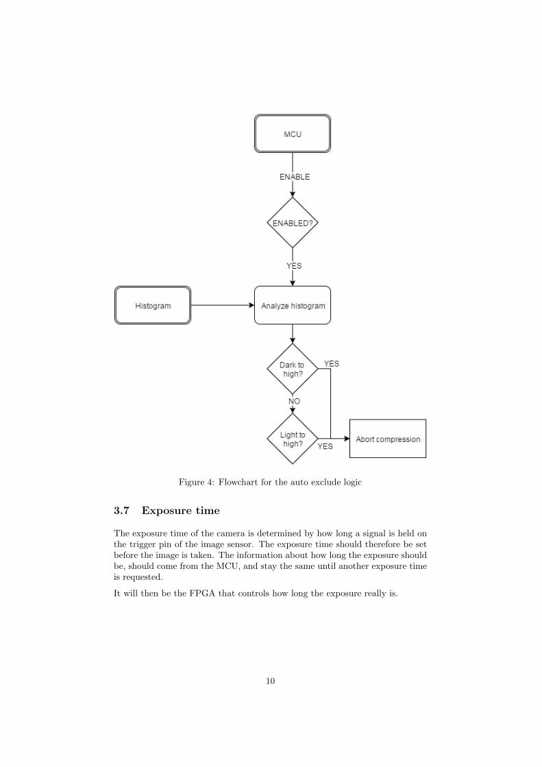
Figure 4: Flowchart for the auto exclude logic
3.7 Exposure time
The exposure time of the camera is determined by how long a signal is held onthe trigger pin of the image sensor. The exposure time should therefore be setbefore the image is taken. The information about how long the exposure shouldbe, should come from the MCU, and stay the same until another exposure timeis requested.
It will then be the FPGA that controls how long the exposure really is.
10
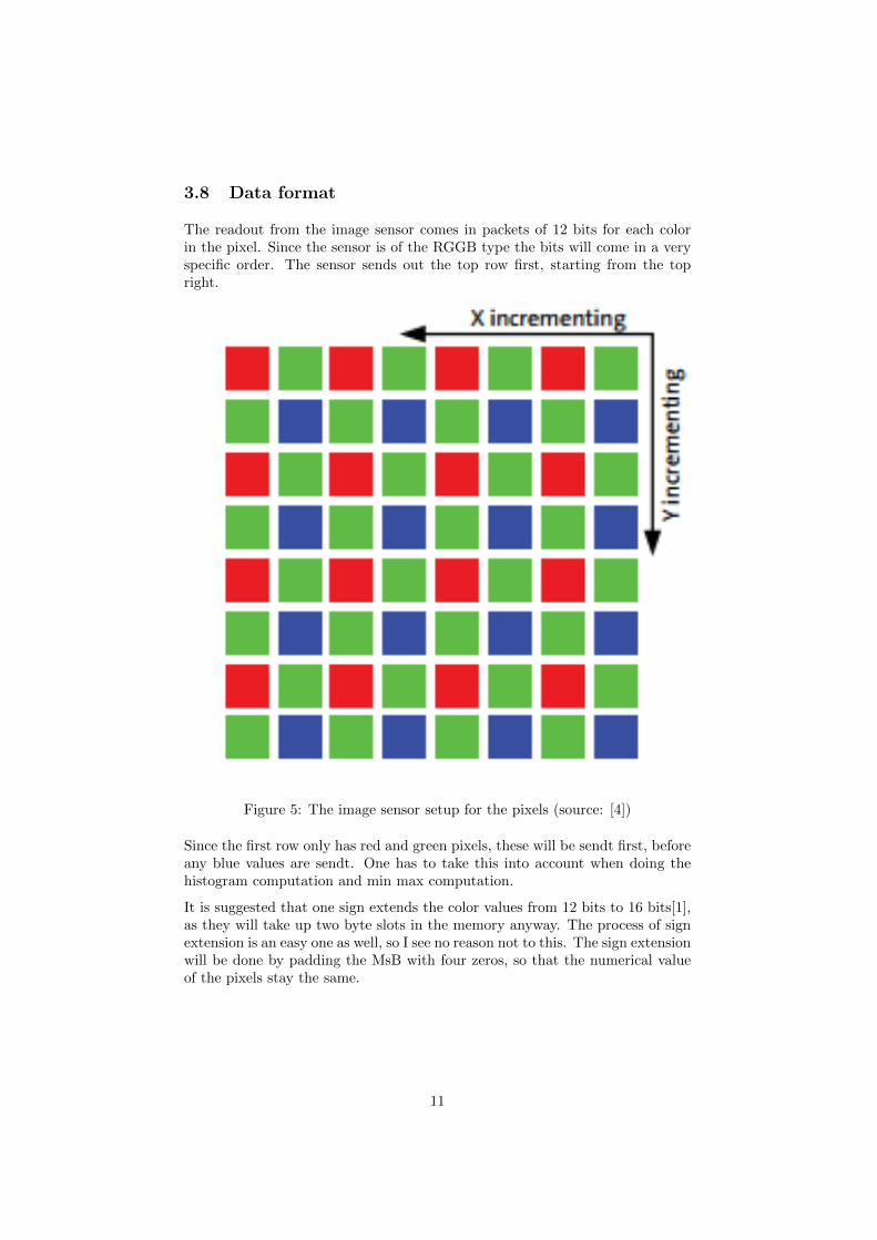
3.8 Data format
The readout from the image sensor comes in packets of 12 bits for each colorin the pixel. Since the sensor is of the RGGB type the bits will come in a veryspecific order. The sensor sends out the top row first, starting from the topright.
Figure 5: The image sensor setup for the pixels (source: [4])
Since the first row only has red and green pixels, these will be sendt first, beforeany blue values are sendt. One has to take this into account when doing thehistogram computation and min max computation.
It is suggested that one sign extends the color values from 12 bits to 16 bits[1],as they will take up two byte slots in the memory anyway. The process of signextension is an easy one as well, so I see no reason not to this. The sign extensionwill be done by padding the MsB with four zeros, so that the numerical valueof the pixels stay the same.
11

Figure 6: The data stream from the image sensor (source: [4])
3.9 Gamma correction
The problem with the gamma correction is that the exponent is between 0 and1. Therefore it is not a straightforward mathematical operation in VHDL. Theproposed exponent of 1/2.2 is quite close to 1/2, which would mean taking thesquare root of the initial value.
Taking the square root of an input is something there exists solutions for, whichcan be altered to suit our needs.
The original code[6] was a function. I changed it to be its own architecture,with some changes to the code to handle the incoming data stream. I also madea test bench to test if this design works.
12

4 Results
4.1 Design implementation
ID SpecificationD04-CAM-COM-001 COM = Internal Communication Bus
Communication with the back plane will be done with an MCUvia the CAN-bus
D04-CAM-COM-002 The OBC will send an image capture request, which the MCUwill handle and execute.
D04-CAM-COM-003 The MCU will retrieve compressed images from the local memoryand pass them to the correct subsystem.
D04-CAM-COM-004 The MCU will be able to change the parameters; gain, frame rate,frame size, exposure. This will be done by receiving commandsfrom the OBC, and pass them along to the FPGA, which controlsthe image sensor.
D04-CAM-CPR-001 CPR = Compression of imagesAn FPGA will handle the raw image data from the image sensor,and compress them using a JPEG-2000 standard.
D04-CAM-CPR-002 The JPEG-2000 standard has the ability to read out a thumbnailof a full-scale image by only using parts of the image data
D04-CAM-CPR-003 The FPGA will create a histogram from the pixel values whilereading the raw data from the image sensor
D04-CAM-CPR-004 The FPGA will read the histogram, and if abnormally high or lowpixel values are found, the compression will not be executed.
D04-CAM-CPR-005 The FPGA will handle the gamma correction during the imagecapture phase, before the compression.
D04-CAM-IMG-001 IMG = Storing of imagesThe images will be stored using a local non-volatile memory, inthis case, an appropriately sized SD-card. The FPGA will storethe compressed images on this memory
D04-CAM-IMG-002 The MCU will read the memory to retrieve the compressed images.D04-CAM-REP-001 REP = Reprogramming
The FPGA gets its bit-file from an external memory, and theMCU has access to this memory for reprogramming purposes
4.2 Min max computation
The min max VHDL code was tested with a test bench in active HDL. Thesimulation shows that it will put out the minimum and maximum value correctly.The code for the min max computation and its test bench can be found in theappendix.
4.3 Gamma correction
The gamma correction code was tested with a self build test bench in activeHDL. The simulations in the test bench shows that the logic works correctly.
13

The code for the gamma correction and its test bench can be found in theappendix.
14

5 Discussion
5.1 JPEG2000 vs JPEG-LS
JPEG2000 and JPEG-LS both have good reasons to be the chosen format forthe satellite image system. Both systems are resilient to bit-flips renderingimages useless or majorly distorted, something the normal JPEG standard isvery susceptible to. JPEG2000 was suggested by a group from ”experts inteam”[2], while JPEG-LS has come up a fair amount of time during my researchon this assignment, because of its existing use.
JPEG-LS is already used extensively in NASA satellites and has a better com-pression rate for lossless images than the JPEG2000 format can achieve [7].JPEG-LS is also easier to implement into an FPGA, because of already existingIPs, and an overall easier compression process. The big drawback with JPEG-LS is that it does not support lossy compression of images and therefore cannot produce images with very high compression.
JPEG2000s biggest strength is the ability to both process images into losslessand lossy compression. This makes it possible to use the same architecture tocompress images to the most useful format at the moment.
The biggest issue for the images on the satellite is their file size. There is avery limited number of megabytes that can be sent from the satellite every day.Therefore the most important task is to compress the images into a size thatis small enough. In raw format, the image will be 9,6 MB[1, page 10], which istoo big to be sent directly. Lossless compression will still yield image sizes thatare too big for the limitation on data transfer.
Even though the lossy compressed image will have lost some data, most of thisdata will be unimportant for the overall quality of the image. Some of this datacan for example be noise. So even if we lose some data, it is more importantto have an image that we are able to send to earth at all, than an image withno lost data, that never gets transferred to earth, or will take so much time totransfer that the satellite will not be able to do other tasks than transfer theimage.
Therefore JPEG2000 will be the chosen format for the images taken with thesatellite.
5.2 SD-card
There is a question of what sort of non-volatile memory to use for the storage ofthe images taken by the camera. The SD-card is a tempting solution because ofits simple implementation and high usage in already existing camera systems.The problem is that there does not exist any good documentation on how theybehave in space. There is also little use of them in other satellites.
15

5.3 In flight reprogramming
If one opens the possibility for in flight reprogramming, one also makes thesystem able to correct eventual errors that might come from bit-flips in theprogram memory of the FPGA. But it also opens up for new errors, where thebit-file can be reprogrammed by error, and therefore render the camera non-working until the error is discovered. I think that the possibility of correctingthe possible errors from bit-flips, and the potential of reprogramming in flight,far outweigh the downside of the possibility of erroneous programming.
5.4 Future work
The logical continuation is to continue the process of implementing the jaspercodec into the FPGA and run tests on the finished logic. Other things to lookat is to test the possibility to change the FPGA bit-file in flight, so that onecan change the picture analysis in the future if one wants that.
16

6 Conclusion
It is possible to make the compression work in the FPGA. It is also possibleto implement an in flight reprogramming, but this has to be included in thecircuit design. The choice of JPEG2000 seems like a sound choice consideringthat it has low distortion when exposed to bit flips, a file format that allows forreadable pictures, even after a partial download. And it also has the possibilityof high compression rates.
References
[1] Andreas Bertheusen, Digital processing system for a Cubesat camera, [online]available: https://www.ntnu.no/wiki/download/attachments/63574301/digital processing for cubesat camera andreas bertheussen.pdf?api=v2
[2] Nicolas Oppheim Bakkebø, Eirik Lund Flogard, Martin Gammelsæter,Hakon Sveinssønn Mork, Antoine F.X. Pignede, Stian Solberg, [online]available: https://www.ntnu.no/wiki/download/attachments/63574301/Bildekomprimering.pdf?version=1&modificationDate=1423675763000&api=v2
[3] Thomas Hanssen Nornes, PROTOTYPE DESIGN FOR CUBESAT CAM-ERA, [online]available: https://www.ntnu.no/wiki/download/attachments/63574301/prototype design for cubesat by thomas hanssen nornes.pdf?version=1&modificationDate=1420909519000&api=v2
[4] ON Semiconductor, 1/2.5-Inch 5 Mp CMOS Digital Image Sensor,MT9P031 Datasheet, Rev. J [online]available: http://www.onsemi.com/pub link/Collateral/MT9P031-D.PDF
[5] David S. Taubman and Michael W. Marcellin, JPEG2000 image compressionfundamentals, standards and practice[ISBN 0-7923-7519-X]
[6] vipin, A VHDL Function for finding SQUARE ROOT [online]available: http://vhdlguru.blogspot.no/2010/03/vhdl-function-for-finding-square-root.html
[7] Joint bi-level image experts group, A study of JPEG 2000 still image codingversus other standards, [online]available: http://old.jpeg.org/public/wg1n1814.pdf
17

Appendix
Gamma correction
library IEEE;
use IEEE.std_logic_1164.all;
use ieee.numeric_std.all;
entity gamma is
port(
clk : in std_logic;
rst : in std_logic;
X : in unsigned(15 downto 0);
Xg : out unsigned(15 downto 0)
);
end entity gamma;
architecture RTL of gamma is
begin
sqrt: process (clk, rst) is
variable a : unsigned(31 downto 0):=(others => ’0’); --original input.
variable q : unsigned(15 downto 0):=(others => ’0’); --result.
variable left,right,r : unsigned(17 downto 0):=(others => ’0’); --input to adder/sub.r-remainder.
variable i : integer:=0;
begin
a(15 downto 0) := X;
a(31 downto 16) := "0000000000000000";
q:=(others => ’0’);
left:=(others => ’0’);
right:=(others => ’0’);
r:=(others => ’0’);
for i in 0 to 15 loop
right(0):=’1’;
right(1):=r(17);
right(17 downto 2):=q;
left(1 downto 0):=a(31 downto 30);
left(17 downto 2):=r(15 downto 0);
a(31 downto 2):=a(29 downto 0); --shifting by 2 bit.
if ( r(17) = ’1’) then
r := left + right;
18

else
r := left - right;
end if;
q(15 downto 1) := q(14 downto 0);
q(0) := not r(17);
end loop;
Xg <= q;
end process;
end architecture;
19

Gamma correction test bench
library IEEE;
use IEEE.std_logic_1164.all;
use ieee.numeric_std.all;
entity gamma_tb is
end gamma_tb;
architecture behavior of gamma_tb is
component gamma
port(
clk : in std_logic := ’0’;
rst : in std_logic := ’0’;
X : in unsigned(15 downto 0) := (others => ’0’);
Xg : out unsigned(15 downto 0) := (others => ’0’)
);
end component;
signal clk, rst : std_logic;
signal X, Xg : unsigned(15 downto 0);
constant clk_period : time := 1 ns;
begin
uut: gamma port map(
clk => clk,
rst => rst,
X => X,
Xg => Xg
);
clk_process: process
begin
clk <= ’0’;
wait for clk_period/2;
clk <= ’1’;
wait for clk_period/2;
end process;
stim_proc: process
begin
X <= x"0000";
wait for 1 ns;
X <= x"0002";
wait for 1 ns;
X <= x"0004";
20
wait for 1 ns;
X <= x"0009";
wait for 1 ns;
X <= x"0010";
wait for 1 ns;
X <= x"0020";
wait for 1 ns;
X <= x"0030";
wait for 1 ns;
X <= x"0100";
wait for 1 ns;
X <= x"2500";
wait for 1 ns;
X <= x"0590";
wait for 1 ns;
X <= x"0099";
wait for 1 ns;
X <= x"0016";
wait for 1 ns;
X <= x"0032";
wait for 1 ns;
X <= x"0042";
wait for 1 ns;
X <= x"0019";
wait for 1 ns;
X <= x"0030";
wait for 1 ns;
X <= x"0040";
wait for 1 ns;
X <= x"0090";
wait for 1 ns;
X <= x"0120";
wait for 1 ns;
X <= x"0151";
wait for 1 ns;
end process;
end;
21
histogram
library IEEE;
use IEEE.STD_LOGIC_1164.ALL;
use IEEE.STD_LOGIC_ARITH.ALL;
use IEEE.STD_LOGIC_UNSIGNED.ALL;
entity histogram is
port(
clk : in std_logic;
rst : in std_logic;
R : in integer;
G : in integer;
B : in integer;
histR : out integer;
histG : out integer;
histB : out integer
);
end entity histogram;
architecture RTL of histogram is
--signals goes here
type row_t is array(0 to 63) of integer;
signal histR_t : row_t;
signal histG_t : row_t;
signal histB_t : row_t;
begin
histogram: process(clk, rst) is
variable bin_number_R : integer :=0;
variable bin_number_G : integer :=0;
variable bin_number_B : integer :=0;
begin
if (rst=’1’) then
histR <= 0;
histG <= 0;
histB <= 0;
else
bin_number_R := R/ 64;
bin_number_G := G/ 64;
bin_number_B := B/ 64;
histR_t(bin_number_R) <= (histR_t(bin_number_R) + 1);
22

histG_t(bin_number_G) <= (histG_t(bin_number_G) + 1);
histR_t(bin_number_B) <= (histR_t(bin_number_B) + 1);
histR <= histR_t(1);
histG <= histG_t(1);
histB <= histB_t(1);
end if;
end process histogram;
end architecture;
23

Histogram test bench
library IEEE;
use IEEE.STD_LOGIC_1164.ALL;
use IEEE.STD_LOGIC_ARITH.ALL;
use IEEE.STD_LOGIC_UNSIGNED.ALL;
entity histogram_tb is
end entity;
architecture behavior of histogram_tb is
component histogram
port(
clk : in std_logic;
rst : in std_logic;
R : in integer;
G : in integer;
B : in integer;
histR : out integer;
histG : out integer;
histB : out integer
);
end component;
signal clk : std_logic;
signal rst : std_logic :=’0’;
signal R,G,B : integer :=0;
signal HistR,HistG,HistB : integer := 0;
constant clk_period : time := 1 ns;
begin
uut: histogram port map (
clk => clk,
rst => rst,
R => R,
G => G,
B => B,
HistR => HistR,
HistG => HistG,
HistB => HistB
);
clk_process: process
begin
clk <= ’0’;
wait for clk_period/2;
clk <= ’1’;
24

wait for clk_period/2;
end process;
stim_proc: process
begin
R <= 4000;
G <= 5;
B <= 156;
wait for 1 ns;
R <= 1;
G <= 250;
B <= 1156;
wait for 1 ns;
R <= 1;
G <= 555;
B <= 1156;
wait for 1 ns;
R <= 1;
G <= 5;
B <= 2156;
wait for 1 ns;
R <= 1;
G <= 500;
B <= 3156;
wait for 1 ns;
end process;
end;
25

Min max computation
library IEEE;
use IEEE.STD_LOGIC_1164.ALL;
use IEEE.STD_LOGIC_ARITH.ALL;
use IEEE.STD_LOGIC_UNSIGNED.ALL;
entity minmax is
port(
clk : in std_logic;
rst : in std_logic;
R : in std_logic_vector(15 downto 0);
G_0 : in std_logic_vector(15 downto 0);
G_1 : in std_logic_vector(15 downto 0);
B : in std_logic_vector(15 downto 0);
maxR : out std_logic_vector(15 downto 0);
maxG_0: out std_logic_vector(15 downto 0);
maxG_1 : out std_logic_vector(15 downto 0);
maxB : out std_logic_vector(15 downto 0);
minR : out std_logic_vector(15 downto 0);
minG_0 : out std_logic_vector(15 downto 0);
minG_1 : out std_logic_vector(15 downto 0);
minB : out std_logic_vector(15 downto 0)
);
end entity minmax;
architecture RTL of minmax is
--signals goes here
signal maxR_t : std_logic_vector(15 downto 0):= "0000000000000000";
signal maxG_0_t : std_logic_vector(15 downto 0):= "0000000000000000";
signal maxG_1_t : std_logic_vector(15 downto 0):= "0000000000000000";
signal maxB_t : std_logic_vector(15 downto 0):= "0000000000000000";
signal minR_t : std_logic_vector(15 downto 0):= "1111111111111111";
signal minG_0_t : std_logic_vector(15 downto 0):= "1111111111111111";
signal minG_1_t : std_logic_vector(15 downto 0):= "1111111111111111";
signal minB_t : std_logic_vector(15 downto 0):= "1111111111111111";
signal max_temp : std_logic_vector(15 downto 0):= "0000000000000000";
signal min_temp : std_logic_vector(15 downto 0):= "1111111111111111";
begin
maximum : process(clk, rst) is
begin
if R > maxR_t then
maxR <= R;
maxR_t <= R;
end if;
if B > maxB_t then
maxB <= B;
maxB_t <= B;
26
end if;
if G_0 > maxG_0_t then
maxG_0 <= G_0;
maxG_0_t <= G_0;
end if;
if G_1 > maxG_1_t then
maxG_1 <= G_1;
maxG_1_t <= G_1;
end if;
end process maximum;
minimum : process(clk,rst) is
begin
if R < minR_t then
minR <= R;
minR_t <= R;
end if;
if B < minB_t then
minB <= B;
minB_t <= B;
end if;
if G_0 < minG_0_t then
minG_0 <= G_0;
minG_0_t <= G_0;
end if;
if G_1 < minG_1_t then
minG_1 <= G_1;
minG_1_t <= G_1;
end if;
end process minimum;
end architecture;
27

Min max computation test bench
library IEEE;
use IEEE.STD_LOGIC_1164.ALL;
use IEEE.STD_LOGIC_ARITH.ALL;
use IEEE.STD_LOGIC_UNSIGNED.ALL;
entity minmax_tb is
end minmax_tb;
architecture behavior of minmax_tb is
component minmax
port(
clk : in std_logic;
rst : in std_logic;
R : in std_logic_vector(15 downto 0);
G_0 : in std_logic_vector(15 downto 0);
G_1 : in std_logic_vector(15 downto 0);
B : in std_logic_vector(15 downto 0);
maxR : out std_logic_vector(15 downto 0);
maxG_0: out std_logic_vector(15 downto 0);
maxG_1 : out std_logic_vector(15 downto 0);
maxB : out std_logic_vector(15 downto 0);
minR : out std_logic_vector(15 downto 0);
minG_0 : out std_logic_vector(15 downto 0);
minG_1 : out std_logic_vector(15 downto 0);
minB : out std_logic_vector(15 downto 0)
);
end component;
signal clk : std_logic := ’0’;
signal rst : std_logic := ’0’;
signal R : std_logic_vector(15 downto 0) := "0000111100001111";
signal G_0 : std_logic_vector(15 downto 0):= "0000111100001111";
signal G_1 : std_logic_vector(15 downto 0):= "0000111100001111";
signal B : std_logic_vector(15 downto 0):= "0000111100001111";
signal maxR : std_logic_vector(15 downto 0):= "0000000000000000";
signal maxG_0 : std_logic_vector(15 downto 0):= "0000000000000000";
signal maxG_1 : std_logic_vector(15 downto 0):= "0000000000000000";
signal maxB : std_logic_vector(15 downto 0):= "0000000000000000";
signal minR : std_logic_vector(15 downto 0):= "1111111111111111";
signal minG_0 : std_logic_vector(15 downto 0):= "1111111111111111";
signal minG_1 : std_logic_vector(15 downto 0):= "1111111111111111";
signal minB : std_logic_vector(15 downto 0):= "1111111111111111";
constant clk_period : time := 1ns;
begin
28

uut: minmax port map (
clk => clk,
rst => rst,
R => R,
G_0 => G_0,
G_1 => G_1,
B => B,
maxR => maxR,
maxG_0 => maxG_0,
maxG_1 => maxG_1,
maxB => maxB,
minR => minR,
minG_0 => minG_0,
minG_1 => minG_1,
minB => minB
);
clk_process: process
begin
clk <= ’0’;
wait for clk_period/2;
clk <= ’1’;
wait for clk_period/2;
end process;
stim_process: process
begin
R <= "0000111100001111";
G_0 <= "0000111100001111";
G_1 <= "0000111100001111";
B <= "0000111100001111";
wait for 1 ns;
R <= "0010111100001111";
G_0 <= "0100111100001111";
G_1 <= "0100111100001111";
B <= "0100111100001111";
wait for 1 ns;
R <= "0010111100001111";
G_0 <= "0010111100001111";
G_1 <= "0010111100001111";
B <= "0010111100001111";
wait for 1 ns;
R <= "0000101100001111";
G_0 <= "0000110100001111";
G_1 <= "0000110000001111";
B <= "0000000000001111";
wait for 1 ns;
R <= "1100111100001111";
G_0 <= "0000011100001111";
G_1 <= "0000000000001111";
29

B <= "0000101100001111";
wait for 1 ns;
R <= "0000111100001111";
G_0 <= "0010111100001111";
G_1 <= "0000111101101111";
B <= "1111111100001111";
wait for 1 ns;
R <= "0000111100001111";
G_0 <= "0000111100001111";
G_1 <= "0000111100001111";
B <= "0000111100000000";
wait for 1 ns;
R <= "0000111100001111";
G_0 <= "0000111100001111";
G_1 <= "0000111100001111";
B <= "0000111100001111";
wait for 1 ns;
R <= "0000111100111111";
G_0 <= "0000101000001111";
G_1 <= "0000111101001001";
B <= "0000111101101111";
wait for 1 ns;
end process;
end;
30
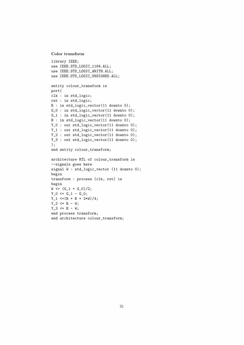
Color transform
library IEEE;
use IEEE.STD_LOGIC_1164.ALL;
use IEEE.STD_LOGIC_ARITH.ALL;
use IEEE.STD_LOGIC_UNSIGNED.ALL;
entity colour_transform is
port(
clk : in std_logic;
rst : in std_logic;
R : in std_logic_vector(11 downto 0);
G_0 : in std_logic_vector(11 downto 0);
G_1 : in std_logic_vector(11 downto 0);
B : in std_logic_vector(11 downto 0);
Y_0 : out std_logic_vector(11 downto 0);
Y_1 : out std_logic_vector(11 downto 0);
Y_2 : out std_logic_vector(11 downto 0);
Y_3 : out std_logic_vector(11 downto 0);
);
end entity colour_transform;
architecture RTL of colour_transform is
--signals goes here
signal W : std_logic_vector (11 downto 0);
begin
transform : process (clk, rst) is
begin
W <= (G_1 + G_0)/2;
Y_0 <= G_1 - G_0;
Y_1 <=(R + B + 2*W)/4;
Y_2 <= R - W;
Y_3 <= B - W;
end process transform;
end architecture colour_transform;
31