picsimlab 0.8
TRANSCRIPT

PICSimLab 0.8.9
Luis Claudio Gambôa Lopes <[email protected]>
Download: github
HTML version of documentation
PICSimLab on Twitter
PICSimLab on Discord
September 27, 2021

Contents
1 Introduction 2
2 Install 42.1 Stable version executables download . . . . . . . . . . . . . . . . . . 42.2 Unstable version executables download . . . . . . . . . . . . . . . . 42.3 Install from source . . . . . . . . . . . . . . . . . . . . . . . . . . . 4
2.3.1 Linux . . . . . . . . . . . . . . . . . . . . . . . . . . . . . . 42.3.2 Windows . . . . . . . . . . . . . . . . . . . . . . . . . . . . 52.3.3 macOS . . . . . . . . . . . . . . . . . . . . . . . . . . . . . 52.3.4 Experimental version . . . . . . . . . . . . . . . . . . . . . . 5
3 Simulator Interface 63.1 Main Window . . . . . . . . . . . . . . . . . . . . . . . . . . . . . . 63.2 Interaction with the Board . . . . . . . . . . . . . . . . . . . . . . . 83.3 Command Line . . . . . . . . . . . . . . . . . . . . . . . . . . . . . 93.4 Remote Control Interface . . . . . . . . . . . . . . . . . . . . . . . . 93.5 Picture Map Reference . . . . . . . . . . . . . . . . . . . . . . . . . 12
4 Boards 144.1 Breadboard . . . . . . . . . . . . . . . . . . . . . . . . . . . . . . . 164.2 McLab1 . . . . . . . . . . . . . . . . . . . . . . . . . . . . . . . . . 164.3 K16F . . . . . . . . . . . . . . . . . . . . . . . . . . . . . . . . . . 174.4 McLab2 . . . . . . . . . . . . . . . . . . . . . . . . . . . . . . . . . 184.5 PICGenios . . . . . . . . . . . . . . . . . . . . . . . . . . . . . . . . 194.6 PQDB . . . . . . . . . . . . . . . . . . . . . . . . . . . . . . . . . . 214.7 Arduino Uno . . . . . . . . . . . . . . . . . . . . . . . . . . . . . . 214.8 Franzininho DIY . . . . . . . . . . . . . . . . . . . . . . . . . . . . 22
5 Experimental Boards 235.1 Blue Pill . . . . . . . . . . . . . . . . . . . . . . . . . . . . . . . . . 235.2 uCboard . . . . . . . . . . . . . . . . . . . . . . . . . . . . . . . . . 235.3 gpboard . . . . . . . . . . . . . . . . . . . . . . . . . . . . . . . . . 245.4 STM32 H103 . . . . . . . . . . . . . . . . . . . . . . . . . . . . . . 245.5 X . . . . . . . . . . . . . . . . . . . . . . . . . . . . . . . . . . . . 25
1
CONTENTS 2
5.6 Curiosity . . . . . . . . . . . . . . . . . . . . . . . . . . . . . . . . 255.7 Curiosity HPC . . . . . . . . . . . . . . . . . . . . . . . . . . . . . . 265.8 Xpress . . . . . . . . . . . . . . . . . . . . . . . . . . . . . . . . . . 26
6 Serial Communication 286.1 Com0com Installation and Configuration(Windows) . . . . . . . . . . 286.2 tty0tty Installation and Configuration (Linux) . . . . . . . . . . . . . 30
7 Debug Support 327.1 MPLABX Integrated Debug (picsim and simavr) . . . . . . . . . . . 327.2 Arduino IDE Integration (simavr) . . . . . . . . . . . . . . . . . . . 327.3 avr-gdb Debug (simavr) . . . . . . . . . . . . . . . . . . . . . . . . 337.4 arm-gdb Debug (qemu-stm32) . . . . . . . . . . . . . . . . . . . . . 337.5 uCsim Debug . . . . . . . . . . . . . . . . . . . . . . . . . . . . . . 33
8 Tools 348.1 Serial Terminal . . . . . . . . . . . . . . . . . . . . . . . . . . . . . 348.2 Serial Remote Tank . . . . . . . . . . . . . . . . . . . . . . . . . . . 34
8.2.1 Actuators . . . . . . . . . . . . . . . . . . . . . . . . . . . . 358.2.2 Sensors . . . . . . . . . . . . . . . . . . . . . . . . . . . . . 368.2.3 Communication Protocol . . . . . . . . . . . . . . . . . . . . 36
8.3 Esp8266 Modem Simulator . . . . . . . . . . . . . . . . . . . . . . . 378.3.1 Supported Commands . . . . . . . . . . . . . . . . . . . . . 38
8.4 Arduino Bootloader . . . . . . . . . . . . . . . . . . . . . . . . . . . 388.5 MPLABX Debugger Plugin . . . . . . . . . . . . . . . . . . . . . . 388.6 Pin Viewer . . . . . . . . . . . . . . . . . . . . . . . . . . . . . . . . 39
9 Oscilloscope 40
10 Spare Parts 4110.1 Pin Alias . . . . . . . . . . . . . . . . . . . . . . . . . . . . . . . . . 4410.2 Inputs . . . . . . . . . . . . . . . . . . . . . . . . . . . . . . . . . . 46
10.2.1 DS1621 (Temperature I2C) . . . . . . . . . . . . . . . . . . . 4610.2.2 Encoder . . . . . . . . . . . . . . . . . . . . . . . . . . . . . 4610.2.3 FM50 (Temperature) . . . . . . . . . . . . . . . . . . . . . . 4610.2.4 Fixed Voltage . . . . . . . . . . . . . . . . . . . . . . . . . . 4710.2.5 Gamepad . . . . . . . . . . . . . . . . . . . . . . . . . . . . 4710.2.6 Gamepad (Analogic) . . . . . . . . . . . . . . . . . . . . . . 4910.2.7 Keypad . . . . . . . . . . . . . . . . . . . . . . . . . . . . . 4910.2.8 LM35 (Temperature) . . . . . . . . . . . . . . . . . . . . . . 5110.2.9 MPU6050 . . . . . . . . . . . . . . . . . . . . . . . . . . . . 5110.2.10 Potentiometers . . . . . . . . . . . . . . . . . . . . . . . . . 5210.2.11 Potentiometers (Rotary) . . . . . . . . . . . . . . . . . . . . 5310.2.12 Push Buttons . . . . . . . . . . . . . . . . . . . . . . . . . . 5310.2.13 Push Buttons (Analogic) . . . . . . . . . . . . . . . . . . . . 5410.2.14 SHT3X (Temp. Hum.) . . . . . . . . . . . . . . . . . . . . . 54

CONTENTS 3
10.2.15 Switches . . . . . . . . . . . . . . . . . . . . . . . . . . . . 5510.2.16 Ultrasonic HC-SR04 . . . . . . . . . . . . . . . . . . . . . . 55
10.3 Outputs . . . . . . . . . . . . . . . . . . . . . . . . . . . . . . . . . 5510.3.1 7 Segments Display . . . . . . . . . . . . . . . . . . . . . . . 5510.3.2 7 Segments Display (Decoder) . . . . . . . . . . . . . . . . . 5610.3.3 Buzzer . . . . . . . . . . . . . . . . . . . . . . . . . . . . . 5710.3.4 DC Motor . . . . . . . . . . . . . . . . . . . . . . . . . . . . 5710.3.5 LCD hd44780 . . . . . . . . . . . . . . . . . . . . . . . . . 5710.3.6 LCD ili9341 . . . . . . . . . . . . . . . . . . . . . . . . . . 5910.3.7 LCD pcf8833 . . . . . . . . . . . . . . . . . . . . . . . . . . 6010.3.8 LCD pcd8544 . . . . . . . . . . . . . . . . . . . . . . . . . 6010.3.9 LCD ssd1306 . . . . . . . . . . . . . . . . . . . . . . . . . 6010.3.10 LED Matrix . . . . . . . . . . . . . . . . . . . . . . . . . . . 6110.3.11 LEDs . . . . . . . . . . . . . . . . . . . . . . . . . . . . . . 6110.3.12 RGB LED . . . . . . . . . . . . . . . . . . . . . . . . . . . 6210.3.13 Servo Motor . . . . . . . . . . . . . . . . . . . . . . . . . . 6310.3.14 Step Motor . . . . . . . . . . . . . . . . . . . . . . . . . . . 63
10.4 Others . . . . . . . . . . . . . . . . . . . . . . . . . . . . . . . . . . 6410.4.1 ETH w5500 . . . . . . . . . . . . . . . . . . . . . . . . . . . 6410.4.2 IO 74xx595 . . . . . . . . . . . . . . . . . . . . . . . . . . . 6510.4.3 IO MCP23S17 . . . . . . . . . . . . . . . . . . . . . . . . . 6610.4.4 IO PCF8574 . . . . . . . . . . . . . . . . . . . . . . . . . . 6610.4.5 IO UART . . . . . . . . . . . . . . . . . . . . . . . . . . . . 6610.4.6 Jumper Wires . . . . . . . . . . . . . . . . . . . . . . . . . . 6710.4.7 MEM 24CXXX . . . . . . . . . . . . . . . . . . . . . . . . . 6710.4.8 RTC ds1307 . . . . . . . . . . . . . . . . . . . . . . . . . . 6810.4.9 RTC pfc8563 . . . . . . . . . . . . . . . . . . . . . . . . . . 6810.4.10 SD Card . . . . . . . . . . . . . . . . . . . . . . . . . . . . . 6910.4.11 Temperature System . . . . . . . . . . . . . . . . . . . . . . 69
10.5 Virtual . . . . . . . . . . . . . . . . . . . . . . . . . . . . . . . . . . 7010.5.1 D. Transfer Function . . . . . . . . . . . . . . . . . . . . . . 7010.5.2 IO Virtual Term . . . . . . . . . . . . . . . . . . . . . . . . . 7010.5.3 Signal Generator . . . . . . . . . . . . . . . . . . . . . . . . 7110.5.4 VCD Dump . . . . . . . . . . . . . . . . . . . . . . . . . . . 7110.5.5 VCD Dump (Analogic) . . . . . . . . . . . . . . . . . . . . . 7210.5.6 VCD Play . . . . . . . . . . . . . . . . . . . . . . . . . . . . 72
11 Troubleshooting 74
12 License 75
A Online Simulator 76

CONTENTS 4
B Use with MPLABX 78B.1 Installing the Necessary Tools . . . . . . . . . . . . . . . . . . . . . 78
B.1.1 Install MPLABX IDE and XC8 Compiler . . . . . . . . . . . 78B.1.2 Install PICsimLab . . . . . . . . . . . . . . . . . . . . . . . 79B.1.3 How to Install PICSimLab MPLABX Debugger plugin . . . . 79
B.2 Configuring a New Project in MPLABX . . . . . . . . . . . . . . . . 84B.2.1 Project Creation . . . . . . . . . . . . . . . . . . . . . . . . 84B.2.2 File Creation . . . . . . . . . . . . . . . . . . . . . . . . . . 87B.2.3 PIC Configuration Bits . . . . . . . . . . . . . . . . . . . . . 88B.2.4 Code Example . . . . . . . . . . . . . . . . . . . . . . . . . 89B.2.5 Building the Project . . . . . . . . . . . . . . . . . . . . . . 90
B.3 Program and Debug PICsimLab With MPLABX . . . . . . . . . . . 91B.3.1 Starting PICsimLab . . . . . . . . . . . . . . . . . . . . . . . 91B.3.2 Programming PICsimLab . . . . . . . . . . . . . . . . . . . 91B.3.3 Pausing the Program . . . . . . . . . . . . . . . . . . . . . . 92B.3.4 Restarting the Program . . . . . . . . . . . . . . . . . . . . . 92B.3.5 Running Step by Step . . . . . . . . . . . . . . . . . . . . . 93B.3.6 Stopping Debugger . . . . . . . . . . . . . . . . . . . . . . . 94B.3.7 Disconnect Debugger . . . . . . . . . . . . . . . . . . . . . . 94
B.4 This Tutorial in Video . . . . . . . . . . . . . . . . . . . . . . . . . . 95
C Creating New Boards 96C.1 Creating a New Board . . . . . . . . . . . . . . . . . . . . . . . . . . 96
C.1.1 Board Hardware and Schematic . . . . . . . . . . . . . . . . 96C.1.2 Board Picture . . . . . . . . . . . . . . . . . . . . . . . . . . 99C.1.3 Picture map . . . . . . . . . . . . . . . . . . . . . . . . . . . 101C.1.4 Board code . . . . . . . . . . . . . . . . . . . . . . . . . . . 105C.1.5 Integration with PICsimLab . . . . . . . . . . . . . . . . . . 124C.1.6 Final Result . . . . . . . . . . . . . . . . . . . . . . . . . . . 124

Chapter 1
Introduction
PICSimLab means Programmable IC Simulator LaboratoryPICSimLab is a realtime emulator of development boards with integrated MPLABX/avr-
gdb debugger. PICSimLab supports some picsim microcontrollers and some simavrmicrocontrollers. PICSimLab have integration with MPLABX/Arduino IDE for pro-gramming the boards microcontrollers. As the purpose of PICSimLab is to emulatereal hardware it does not have any source code editing support. For code editing anddebugging the same tools used for a real board should be used with PICSimLab, suchas MPLABX or Arduino IDE.
PICSimLab supports several devices (spare parts) that can be connected to theboards for simulation. As for example LEDs and push buttons for simple outputs andinputs and some more complex ones like the ethernet shield w5500 for internet con-nection or the color graphic display ili9340 with touchscreen. The the complete list ofparts can be accessed in the chapter Spare Parts.
The experimental version boards supports uCsim, gpsim and qemu-stm32 simula-tors in addition to the stable ones.
5

CHAPTER 1. INTRODUCTION 6

Chapter 2
Install
2.1 Stable version executables downloadIf you are on Linux or Windows you can download the last version at:
https://github.com/lcgamboa/picsimlab/releasesIf you are on macOS you can run PICSimLab using Wine:
1. Download and install [‘xquartz‘](https://www.xquartz.org)
2. Download and install [Wine](https://dl.winehq.org/wine-builds/macosx/download.html)
3. Download the executable and double-click it to run the installer
2.2 Unstable version executables downloadThe binaries of last code available on github can be downloaded at: Sourceforge.net
The unstable test version have the unreleased features of Changelog_auto.mdIf you need a specific binary that is not available please contact me.
2.3 Install from source
2.3.1 LinuxIn Debian Linux and derivatives Linux native:
Using a user with permission to run the sudo command:In first time build:
git clone --depth=1 https://github.com/lcgamboa/picsimlab.git
cd picsimlab
./picsimlab_build_all_and_install.sh
To recompile use:
7

CHAPTER 2. INSTALL 8
make -j4
2.3.2 WindowsCross-compiling for Windows (from Linux or WSL on win10)
In first time build in Debian Linux and derivatives target Windows 64 bits:
git clone https://github.com/lcgamboa/picsimlab.git
cd picsimlab
./picsimlab_build_w64.sh
To recompile use:
make FILE=Makefile.cross -j4
For target Windows 32 bits:
git clone https://github.com/lcgamboa/picsimlab.git
cd picsimlab
./picsimlab_build_w32.sh
To recompile use:
make FILE=Makefile.cross_32 -j4
2.3.3 macOSTheoretically it is possible to compile PICSimLab natively on macOS. But I do nothave access to any computer with macOS to try to compile and until today nobody hascommunicated that they managed to do it. (help wanted)
2.3.4 Experimental versionExperimental version can be built using the parameter "exp" on scripts:
./picsimlab_build_all_and_install.sh exp
./picsimlab_build_w64.sh exp
./picsimlab_build_w32.sh exp
And recompiled using the parameter "exp" on Makefiles:
make -j4 exp
make FILE=Makefile.cross -j4 exp
make FILE=Makefile.cross_32 -j4 exp

Chapter 3
Simulator Interface
3.1 Main WindowThe main window consists of a menu, a status bar, a frequency selection combobox,an on/off button to trigger debugging, some board-specific controls and the part of theboard interface itself.
In the title of the window is shown the name of the simulator PICSimLab, followedby the board and the microcontroller in use.
The frequency selection combobox directly changes the working speed of the mi-
9

CHAPTER 3. SIMULATOR INTERFACE 10
crocontroller. The “Spd” label show the ratio between simulation speed and real time.when the “Spd” label goes red indicates that the computer is not being able to run theprogram in real time for the selected clock. In this case the simulation may presentsome difference than expected and the CPU load will be increased.
The on/off button to enable debugging is used to enable debugging support, whenactive simulation load is increased.
The menus and their functions are listed below:
• File
– Load Hex - Load .hex files
– Reload Last - Reload the last used .hex file
– Save Hex - Save memory in a .hex file
– Configure - Open the configuration windows
– Save Workspace - Saves all current workspace settings to a .pzw file
– Load Workspace - Loads saved settings from a .pzw file
– Exit
• Board
– Arduino Uno - Choose board Arduino Uno
– Breadboard - Choose board Breadboard
– Franzininho - Choose board Franzininho
– K16F - Choose board K16F
– McLab1 - Choose board McLab1
– McLab2 - Choose board McLab2
– PICGenios - Choose board PICGenios
– PQDB - Choose board PQDB
• Microcontroller
– xxxxx - Selects the microcontroller to be used (depends on the selectedboard)
• Modules
– Oscilloscope - Open the oscilloscope window
– Spare parts - Open the spare parts window
• Tools
– Serial Terminal - Open the serial terminal Cutecom
– Serial Remote Tank - Open the remote tank simulator
– Esp8266 Modem Simulator - Open the Esp8266 Modem Simulator

CHAPTER 3. SIMULATOR INTERFACE 11
– Arduino Bootloader - Load microcontroller with Arduino serial bootloader
– MPLABX Debugger Plugin - Open the web page to download the MPLABXDebugger Plugin
– Pin Viewer - Open the Pin Viewer
• Help
– Contents - Open the Help window
– Board - Open the Board Help window
– Examples - Load the examples
– About Board - Show message about author and version of board
– About PICSimLab - Show message about author and version of PICSim-Lab
The first part of the status bar shows the state of the simulation, in the middlepart the status of the debug support and in the last part the name of the serial portused, its default speed and the error in relation to the real speed configured in themicrocontroller.
3.2 Interaction with the BoardOn the interface area of the board it is possible to interact in some ways:
• Click in ICSP connector to load an .hex file.
• Click in PWR button to ON/OFF the emulator..
• The buttons can be activated through mouse or keys 1, 2, 3 e 4.
• Click and drag in potentiometers to change their values.
• Click on EEPROM memory to view its contents.

CHAPTER 3. SIMULATOR INTERFACE 12
3.3 Command LinePICSimLab supports two command lines format:
One for load a PICSimLab Workspace file (.pzw)
picsimlab file.pzw
And other for load .hex files
picsimlab boardname microcontroller [file.hex] [file.pcf]
3.4 Remote Control InterfaceThe remote control interface allows other programs to control the PICSimLab simula-tion through a TCP/IP socket using text formatted commands.
The PICSimLab remote control interface supports TCP connections using telnet ornc (netcat).
The default port is 5000 and can be changed in configuration windows.The ’rlwrap’ command can be used for best command edition support in telnet or
nc:
rlwrap nc 127.0.0.1 5000
The supported commands can be shown using the “help” command:
help
List of supported commands:
dumpe [a] [s]- dump internal EEPROM memory
dumpf [a] [s]- dump Flash memory
dumpr [a] [s]- dump RAM memory
exit - shutdown PICSimLab
get ob - get object value
help - show this message
info - show actual setup info and objects
loadhex file - load hex file (use full path)
pins - show pins directions and values
pinsl - show pins formated info
quit - exit remote control interface
reset - reset the board
set ob vl - set object with value
sim [cmd] - show simulation status or execute cmd start/stop
sync - wait to syncronize with timer event
version - show PICSimLab version
Ok
The “info” command show all available "objects" and values:

CHAPTER 3. SIMULATOR INTERFACE 13
info
Board: Arduino Uno
Processor: atmega328p
Frequency: 16000000 Hz
Use Spare: 1
board.out[00] LD_L= 254
part[00]: LEDs
part[00].out[08] LD_1= 254
part[00].out[09] LD_2= 30
part[00].out[10] LD_3= 254
part[00].out[11] LD_4= 254
part[00].out[12] LD_5 254
part[00].out[13] LD_6= 254
part[00].out[14] LD_7= 254
part[01]: Buzzer
part[01].out[02] LD_1= 140
part[02]: Push buttons
part[02].in[00] PB_1= 1
part[02].in[01] PB_2= 0
part[02].in[02] PB_3= 1
part[02].in[03] PB_4= 1
part[02].in[04] PB_5= 1
part[02].in[05] PB_6= 1
part[02].in[06] PB_7= 1
part[02].in[07] PB_8= 1
Ok
The “pins” command show all pins directions and digital values:
pins
pin[01] ( PC6/RST) < 0 pin[15] ( PB1/~9) > 0
pin[02] ( PD0/0) < 1 pin[16] ( PB2/~10) > 0
pin[03] ( PD1/1) < 1 pin[17] ( PB3/~11) > 0
pin[04] ( PD2/2) < 1 pin[18] ( PB4/12) < 0
pin[05] ( PD3/~3) > 0 pin[19] ( PB5/13) > 0
pin[06] ( PD4/4) < 1 pin[20] ( +5V) < 1
pin[07] ( +5V) < 1 pin[21] ( AREF) < 0
pin[08] ( GND) < 0 pin[22] ( GND) < 0
pin[09] ( PB6/X1) < 0 pin[23] ( PC0/A0) < 0
pin[10] ( PB7/X2) < 0 pin[24] ( PC1/A1) < 0
pin[11] ( PD5/~5) < 1 pin[25] ( PC2/A2) < 0
pin[12] ( PD6/~6) < 1 pin[26] ( PC3/A3) < 0
pin[13] ( PD7/7) < 1 pin[27] ( PC4/A4) > 0
pin[14] ( PB0/8) > 0 pin[28] ( PC5/A5) > 0
Ok
The “pinsl” command show all pins info in text formatted output:

CHAPTER 3. SIMULATOR INTERFACE 14
pinsl
28 pins [atmega328p]:
pin[01] D I 0 000 0.000 "PC6/RST "
pin[02] D I 1 200 0.000 "PD0/0 "
pin[03] D I 1 200 0.000 "PD1/1 "
pin[04] D I 1 200 0.000 "PD2/2 "
pin[05] D O 0 007 0.000 "PD3/~3 "
pin[06] D I 1 200 0.000 "PD4/4 "
pin[07] P I 1 200 0.000 "+5V "
pin[08] P I 0 000 0.000 "GND "
pin[09] D I 0 000 0.000 "PB6/X1 "
pin[10] D I 0 000 0.000 "PB7/X2 "
pin[11] D I 1 200 0.000 "PD5/~5 "
pin[12] D I 1 200 0.000 "PD6/~6 "
pin[13] D I 1 200 0.000 "PD7/7 "
pin[14] D O 0 000 0.000 "PB0/8 "
pin[15] D O 0 000 0.000 "PB1/~9 "
pin[16] D O 0 000 0.000 "PB2/~10 "
pin[17] D O 0 006 0.000 "PB3/~11 "
pin[18] D I 0 000 0.000 "PB4/12 "
pin[19] D O 0 000 0.000 "PB5/13 "
pin[20] P I 1 200 0.000 "+5V "
pin[21] R I 0 000 0.000 "AREF "
pin[22] P I 0 000 0.000 "GND "
pin[23] A I 0 000 0.875 "PC0/A0 "
pin[24] A I 0 000 1.925 "PC1/A1 "
pin[25] A I 0 000 2.700 "PC2/A2 "
pin[26] A I 0 000 4.275 "PC3/A3 "
pin[27] D O 1 179 0.000 "PC4/A4 "
pin[28] D O 1 186 0.000 "PC5/A5 "
Ok
You can view one input/output state using the “get” command:
get board.out[00]
get part[02].in[01]
Its possible use the “get” command to view individual pins state:
#digital state
get pin[19]
pin[19]= 0
Ok
#digital mean value (0-200)
get pinm[19]
pin[18]= 100

CHAPTER 3. SIMULATOR INTERFACE 15
Ok
#analog state
get apin[25]
apin[25]= 2.700
Ok
#all info
get pinl[13]
pin[13] D I 1 200 0.000 "PD7/7 "
Ok
And set value of one input using the “set” command:
set part[02].in[01] 0
set part[02].in[01] 1
Or set value of one pin using the “set” command:
#digital
set pin[10] 2
#analog
set apin[20] 2.345
For windows users putty telnet client is a good option to access the remote controlinterface.
3.5 Picture Map ReferenceNames used in .map files for boards and parts are standardized and used by the remotecontrol interface.
The names must start with I_ if it is an input, O_ if it is an output or B_ if it isbidirectional. And be followed by one of the two-letter types in the table below beforethe area name.

CHAPTER 3. SIMULATOR INTERFACE 16
Function Type Description RControl In RControl OutI MD Memory Dump - -I KB Keyboard Key 0 or 1 0 or 1I PG Program - -I CN Connector - -B PO Potentiometer 0 to 200 0 to 200B JP Jumper 0 or 1 0 or 1B VS Value short -32768 to 32767 -32768 to 32767B PB Push button 0 or 1 0 or 1B DP Dip switch 0 or 1 0 or 1B SW Switch 0 or 1 0 or 1B RT Rotary encoder 0 to 200 0 to 200B AJ Dip switch - -O MC Motor Cooler - 0 to 200O PN Pin name - -O ST Status - -O IC IC name - -O LR LED RGB - -O LM LED Matrix - -O DI Display Info - -O LD LED - 0 to 200O DS Display - if alphanumeric show textO MT DC motor - dir 0 or 1, spd. 0 to 200, pos. 0 to 200O DG Degree - float angleO SS seven segment - decoded number
For example area named B_PB_Start, which describes the position of a push but-ton named "Start". The B_ bidirectional indicates that the mapped area serves as useraction input and drawing output.

Chapter 4
Boards
PICSimLab currently supports five backend simulators. The stable version supportspicsim and simavr. The experimental version supports uCsim, gpsim and qemu-stm32in addition to the stable ones.
The Figure 4.1 shows which cards are based on which backend simulator:
17

CHAPTER 4. BOARDS 18
Figure 4.1: Boards backend simulators
The below table show the supported debug interface of each simulator:
Backend Debug Supportpicsim MPLABX Integrated Debug (see section 7.1)simavr MPLABX Integrated Debug (see section 7.1) and remote avr-gdb (see section 7.3)
qemu-stm32 remote arm-gdb (see Chapter 7.4)uCsim uCsim remote console (telnet) (see section 7.5)gpsim none yet

CHAPTER 4. BOARDS 19
4.1 BreadboardIt is a generic board only with reset, serial and crystal circuits and support to multiplemicrocontrollers of picsim and simavr.
Examples
4.2 McLab1It emulates the Labtools development board McLab1 that uses one PIC16F84, PIC16F628or PIC16F648 of picsim.
PIC
ICSP
8 x LEDs
2x 7 segments multiplexed display
4 x push-buttons
lamp (PWM) PO
RT
B
PO
RT
A

CHAPTER 4. BOARDS 20
Board McLab1 schematics.
The code examples can be loaded in PICSimLab menu Help->Examples.The source code of board McLab1 examples using MPLABX and XC8 compiler
are in the link: board_McLab1.
4.3 K16FIt emulates an didactic board developed by author that uses one PIC16F84, PIC16F628or PIC16F648 of picsim.
PIC
ICSP
4 x LEDs PO
RT
B
PO
RT
A
I2C eeprom
RTC
serial
3x4 keyboard
serial LCD 16x2
CHAPTER 4. BOARDS 21
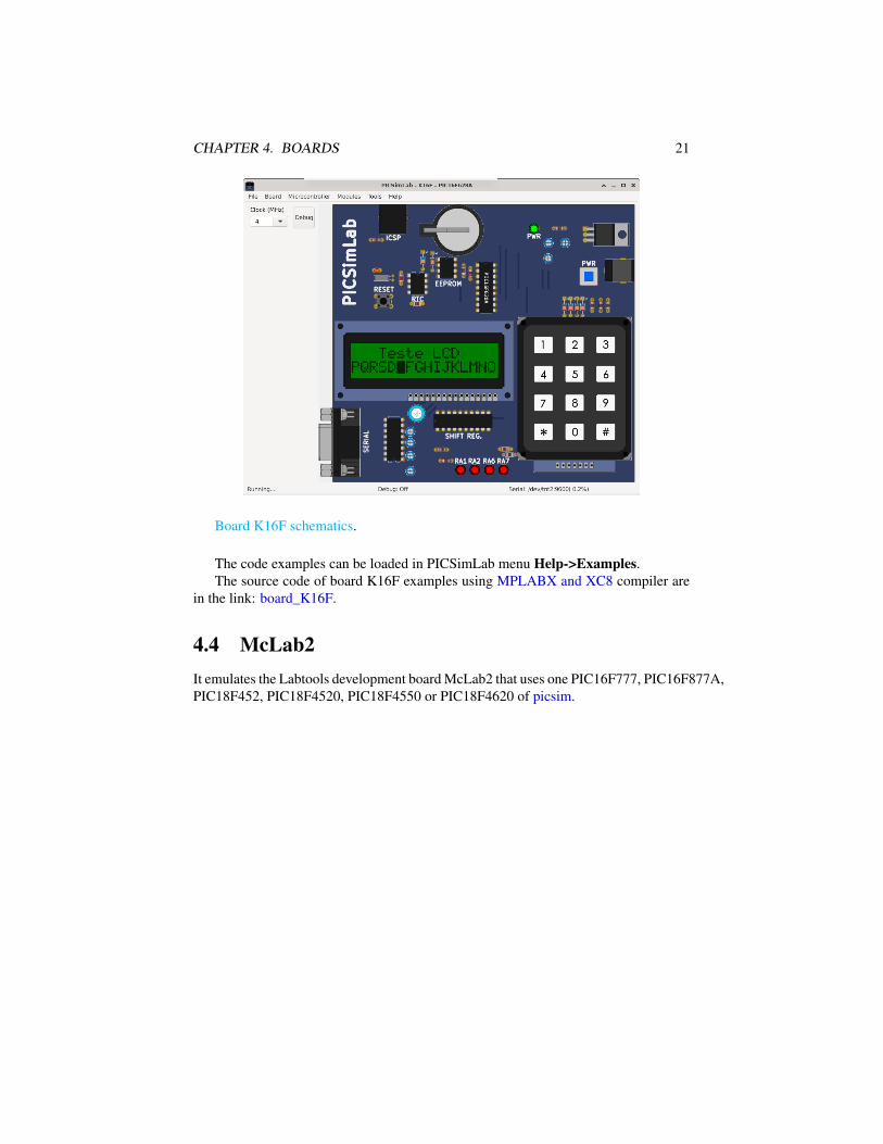
Board K16F schematics.
The code examples can be loaded in PICSimLab menu Help->Examples.The source code of board K16F examples using MPLABX and XC8 compiler are
in the link: board_K16F.
4.4 McLab2It emulates the Labtools development board McLab2 that uses one PIC16F777, PIC16F877A,PIC18F452, PIC18F4520, PIC18F4550 or PIC18F4620 of picsim.

CHAPTER 4. BOARDS 22
PIC
ICSP4 x LEDs
PO
RT
B
PO
RT
A
I2C eeprom
serial LCD 16x2
4x 7 segments multiplexed display
4 x push-buttons
PO
RT
C
PO
RT
D
PORTE
fan
heater
temp. sensor
fan tacometer
buzzer
potentiometer
Board McLab2 schematics.
The code examples can be loaded in PICSimLab menu Help->Examples.The source code of board McLab2 examples using MPLABX and XC8 compiler
are in the link: board_McLab2.
4.5 PICGeniosIt emulates the microgenius development board PICGenios PIC18F e PIC16F Mi-crochip that uses one PIC16F777, PIC16F877A, PIC18F452, PIC18F4520, PIC18F4550or PIC18F4620 of picsim.

CHAPTER 4. BOARDS 23
PIC
ICSP
8 x LEDs
PO
RT
B
PO
RT
AI2C eeprom
serial
LCD 16x2
4x 7 segments multiplexed display
6 x push-buttons
PO
RT
C
PO
RT
D
PORTE
fan
heater
temp. sensor
fan tacometer
buzzer
2 x potentiometer
RTC
3x4 keyboard
8 x LEDs
relay
push-button
PS2
relay
Board PICGenios schematics.
The code examples can be loaded in PICSimLab menu Help->Examples.The source code of board PICGenios examples using MPLABX and XC8 compiler
are in the link: board_PICGenios.

CHAPTER 4. BOARDS 24
4.6 PQDBThe PQDB board is an opensource/openhardware project, more info at https://github.com/projetopqdb/.It was developed to be used with arduino/freedom boards, but adapted to use the mi-crocontroller PIC18F4520 of picsim on PICSImLab.
Examples
4.7 Arduino UnoIt emulates the Arduino Uno development board that uses one ATMEGA328P micro-controller of simavr.

CHAPTER 4. BOARDS 25
Board Arduino Uno schematics.
The code examples can be loaded in PICSimLab menu Help->Examples.The source code of board Arduino Uno examples using the Arduino IDE with avr-
gcc are in the link: board_Arduino_Uno.More information about the Arduino in www.arduino.cc
4.8 Franzininho DIYThe Franzininho DIY board is an openhardware project, more info at https://franzininho.com.br/.It was developed to be used with the microcontroller ATtiny85 of of simavr.
Examples

Chapter 5
Experimental Boards
Boards in the experimental phase. Probably with some bugs and missing features.
5.1 Blue PillIt is a generic board only with reset, serial and crystal circuits and support to stm32f103c8t6microcontroller of qemu-stm32.
Examples
5.2 uCboardIt is a generic board only with reset, serial and crystal circuits and support to multiplemicrocontrollers (initially C51, Z80 and STM8S103 )of uCsim.
26

CHAPTER 5. EXPERIMENTAL BOARDS 27
Examples
5.3 gpboardIt is a generic board only with reset, serial and crystal circuits and support to multiplemicrocontrollers of gpsim.
Examples
5.4 STM32 H103It is a generic board only with reset, one push button, serial and crystal circuits andsupport to stm32f103rbt6 microcontroller of qemu-stm32.

CHAPTER 5. EXPERIMENTAL BOARDS 28
Examples
5.5 XIt is a generic board, used as example in How to Compile PICsimLab and Create NewBoards.
Examples
5.6 CuriosityThis is a simple PIC microcontroller development board that uses picsim.

CHAPTER 5. EXPERIMENTAL BOARDS 29
Examples
5.7 Curiosity HPCThis is a simple PIC microcontroller development board that uses picsim.
Examples
5.8 XpressThis is a simple PIC microcontroller development board that uses picsim.

CHAPTER 5. EXPERIMENTAL BOARDS 30
Examples

Chapter 6
Serial Communication
To use the simulator serial port emulation, you must install a NULL-MODEM emula-tor:
• Windows: com0com http://sourceforge.net/projects/com0com/
• Linux: tty0tty https://github.com/lcgamboa/tty0tty
For communication the PICSimLab should be connected in one port of the NULL-MODEM emulator and the other application connected in the other port. Configurationexamples linking PICSimLab to Cutecom for serial communication:
OS PicsimLab port Cutecom port NULL-Modem prog. ConnectionWindows com1 com2 com0com com1<=>com2
Linux /dev/tnt2 /dev/tnt3 tty0tty /dev/tnt2<=>/dev/tnt3
The PICSimLab serial communication uses the 8N1 format.
6.1 Com0com Installation and Configuration(Windows)Download the signed version of com0com.
Unzip the downloaded .zip file and run the specific installer of your operating sys-tem, x86 for windows 32-bit or x64 for windows 64-bit.
Configure the “choose components” window as the figure below:
31

CHAPTER 6. SERIAL COMMUNICATION 32
In the last configuration window, check the “Launch setup” option:
In the setup window, change the port names to COM1, COM2, COM3 .... Justcheck the “enable buffer overrun” option on the two ports, click in the “Apply” buttonand close the setup. In the configuration shown in the figure below, the COM1 andCOM2 ports form a NULL-MODEM connection, where one port must be used by thePICSimLab and another by the application with serial communication.

CHAPTER 6. SERIAL COMMUNICATION 33
6.2 tty0tty Installation and Configuration (Linux)Download the tty0tyy. Unzip the downloaded folder.
Open a terminal and enter in the tty0tty/module/ folder and enter the followingcommands:
sudo apt-get updatesudo apt-get -y upgradesudo apt-get -y install gcc make linux-headers-`uname -r`sudo ./dkms-install.shsudo modprobe tty0tty
The user must be in the dialout group to access the ports. To add your user todialout group use the command:
sudo usermod -a -G dialout your_user_name
after this is necessary logout and login to group permissions take effect.Once installed, the module creates 8 interconnected ports as follows:
/dev/tnt0 <=> /dev/tnt1/dev/tnt2 <=> /dev/tnt3/dev/tnt4 <=> /dev/tnt5/dev/tnt6 <=> /dev/tnt7
the connection between each pair is of the form:

CHAPTER 6. SERIAL COMMUNICATION 34
TX -> RXRX <- TXRTS -> CTSCTS <- RTSDSR <- DTRCD <- DTRDTR -> DSRDTR -> CD
Any pair of ports form a NULL-MODEM connection, where one port must be usedby the PICSimLab and another by the application with serial communication.

Chapter 7
Debug Support
The type of debug interface depends on the backend simulator utilized.
7.1 MPLABX Integrated Debug (picsim and simavr)To use the MPLABX IDE for debug and program the PicsimLab, install the plugincom-picsim-picsimlab.nbm in MPLABX.
The plugin connect to Picsimlab through a TCP socket using port 1234 (or otherdefined in configuration window), and you have to allow the access in the firewall.
Tutorial: how to use MPLABX to program and debug PICsimLab.It’s possible import and debug a Arduino sketch into MPLABX using the Arduino
import plugin.
7.2 Arduino IDE Integration (simavr)For integrated use with the Arduino IDE, simply configure the serial port as explainedin the section 6 and load the Arduino bootloader. The bootloader can be loaded fromthe “Tools->Arduino bootloader” menu.
In Windows, considering com0com making a NULL-MODEM connection betweenCOM1 and COM2, simply connect the PICSimLab on the COM1 port (defined inconfiguration window) and the Arduino IDE on the COM2 port or vice versa.
On Linux the operation is the same, but using for example the ports /dev/tnt2 and/dev/tnt3.
In Linux for the virtual ports to be detected in Arduino it is necessary to replace thelibrary lib/liblistSerialsj.so of the Arduino with a version which support the detectionof tty0tty ports, that can be downloaded in the link listSerialC with tty0tty support.
35

CHAPTER 7. DEBUG SUPPORT 36
7.3 avr-gdb Debug (simavr)With debug support enabled you can use avr-gdb to debug the code used in the simu-lator. Use the configuration window to choose between MDB (MPLABX) or GDB todebug AVR microcontrollers.
Use avr-gdb with the .elf file as the parameter:
avr-gdb compiled_file.elf
and the command below to connect (1234 is the default port):
target remote localhost:1234
Graphic debug mode can be made using eclipse IDE with Sloeber Arduino plugin.
7.4 arm-gdb Debug (qemu-stm32)With debug support enabled you can use arm-none-eabi-gdb (or gdb-multiarch) to de-bug the code used in the simulator.
Use arm-none-eabi-gdb with the .elf file as the parameter:
arm-none-eabi-gdb compiled_file.elf
and the command below to connect (1234 is the default port):
target remote localhost:1234
Graphic debug mode can be made using eclipse IDE with Eclipse Embedded CDT.
7.5 uCsim DebugThe uCsim debug console can be accessed with the telnet (1234 is the default port):
telnet localhost 1234
All uCsim commands are supported.For windows users putty telnet client is a good option to access the uCsim console.

Chapter 8
Tools
8.1 Serial TerminalOpen the serial terminal Cutecom.
A serial terminal is used to send and receive data over a serial communicationchannel. The use of this terminal can be replaced by others like the Arduino IDE serialmonitor.
To use this tool with PICSimLab you first need to configure a virtual serial port asdescribed in Chapter: Serial Communication. It is possible to use this tool with a realserial port connected to a real device.
8.2 Serial Remote TankThe serial remote tank is a tank simulator controlled by a serial communication proto-col. The tank has several sensors and actuators that can be read and controlled using
37

CHAPTER 8. TOOLS 38
the communication protocol. The parameters of the serial communication port must be19200 8N1.
To use this tool with PICSimLab you first need to configure a virtual serial port asdescribed in Chapter: Serial Communication. It is possible to use this tool with a realserial port connected to a real device.
8.2.1 ActuatorsDigital inputs:
1. Inlet valve
2. Outlet valve
3. Heater
4. Cooler
5. Stirrer
Analog inputs:
1. Minimal temperature alarm trigger level
2. Maximal temperature alarm trigger level

CHAPTER 8. TOOLS 39
8.2.2 SensorsDigital outputs:
1. High floater
2. Low floater
3. Minimal temperature
4. Maximal temperature
Analog outputs:
1. Volume
2. Temperature
8.2.3 Communication ProtocolWriting on Digital Input
Sent one byte in 0x0N hexadecimal format where N is the number of input followedby a second byte with value 0x00 for disable or 0x01 for enable.
Example to turn on the input 2:
Serial_write(0x02);
Serial_write(0x01);
Reading Digital Output
Sent one byte in 0x1N hexadecimal format where N is the number of output and readone byte. The byte readed have value 0x00 for disable or 0x01 for enable.
Example to read output 3:
Serial_write(0x13);
valor=Serial_read(0);
Writing on Analog Input
Sent one byte in 0x2N hexadecimal format where N is the number of input followedby two bytes with the 16 bits value.
Example to write the value 230 on analog input 1:
Serial_write(0x21);
valor=230;
Serial_write((valor&0xFF00)>>8);
Serial_write(valor&0x00FF);

CHAPTER 8. TOOLS 40
Reading Analog Output
Sent one byte in 0x3N hexadecimal format where N is the number of output and readtwo bytes to form the 16 bits value.
Example to read analog output 2:
Serial_write(0x32);
valorh=Serial_read(0);
valorl=Serial_read(0);
valor=(valorh<<8)|valorl;
8.3 Esp8266 Modem SimulatorThe ESP8266 modem simulator emulates the operation of an esp8266 with wifi modemfirmware. Communication is done using a serial channel via AT modem commands.The parameters of the serial communication port must be 115200 8N1.
To use this tool with PICSimLab you first need to configure a virtual serial port asdescribed in Chapter: Serial Communication. It is possible to use this tool with a real

CHAPTER 8. TOOLS 41
serial port connected to a real device.
8.3.1 Supported Commands• AT
• AT+RST
• AT+GMR
• AT+CWMODE=1
• AT+CWDHCP=1,1
• AT+CWLAP
• AT+CWJAP="rede1","123456"
• AT+CIFSR
• AT+CIPMUX=1
• AT+CIPSERVER=1,2000
• AT+CIPSEND=0,10
• AT+CIPCLOSE=0
8.4 Arduino BootloaderThis menu option load PICSimLab microcontroller with Arduino serial bootloader.The microcontroller with the bootloader loaded can be programmed directly by theArduino IDE or using the avrdude program.
To use this tool with PICSimLab you first need to configure a virtual serial port asdescribed in Chapter: Serial Communication.
8.5 MPLABX Debugger PluginThis menu option open the web page to download the MPLABX Debugger Plugin.
The plugin must be installed on MPLABX to allow debugging and programmingPICSimLab (PICs and AVRs) from the IDE, like a real tool for debugging and pro-gramming.

CHAPTER 8. TOOLS 42
8.6 Pin ViewerThe PinViewer connects to PICSimLab through the rcontrol interface and allows view-ing the status and direction of all microcontroller pins. It is also possible to change thestate of the digital pins and adjust the voltage value on the analog pins configured asinput. Pins configured as outputs also show the average value, useful for evaluating thefunctioning of PWM outputs.

Chapter 9
Oscilloscope
The PICSimLab has a basic two-channel oscilloscope that can be used to view thesignal on any pin of the microcontroller. The oscilloscope can be accessed through the“Modules->Oscilloscope” menu.
43
Chapter 10
Spare Parts
The PICSimLab has a window that allows the connection of spare parts to the micro-controller, it can be accessed through the menu “ Modules-> Spare parts ”.
The main window has the menu with the following functions:
• File
– New configuration - Clear the spare parts window
– Save configuration - Saves the current settings of the spare parts into .pcffile
– Load configuration - Loads the settings from .pcf file
– Save pin alias - Saves the current pin alias to .ppa text file
– Load pin alias - Loads the pin alias from .ppa file
• Edit
– Clear pin alias - Clear the pin alias
– Toggle pin alias - Enable/Disable pin alias use
– Edit pin alias - Open current pin alias .ppa file in text editor
– Reload pin alias - Reload the current .ppa pin alias file (need after edit .ppafile)
– Zoom in - Increase draw scale
– Zoom out - Decrease draw scale
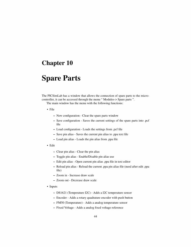
• Inputs
– DS1621 (Temperature I2C) - Adds a I2C temperature sensor
– Encoder - Adds a rotary quadrature encoder with push button
– FM50 (Temperature) - Adds a analog temperature sensor
– Fixed Voltage - Adds a analog fixed voltage reference
44

CHAPTER 10. SPARE PARTS 45
– Gamepad - Adds a gamepad
– Gamepad (Analogic) - Adds a gamepad with one analogic output
– Keypad - Adds one matrix keypad
– LM35 (Temperature) - Adds a analog temperature sensor
– MPU6050 - Adds a accelerometer and gyroscope (only raw values)
– Potentiometers - Adds 4 potentiometers
– Potentiometers (Rotary) - Adds 4 rotary potentiometers
– Push Buttons - Adds 8 push buttons
– Push Buttons (Analogic) - Adds 8 push buttons with analog output
– SHT3X - Adds a analog temperature and humidity sensor
– Switches - Adds eight switches
– Ultrasonic HC-SR04 - Adds a ultrasonic range sensor
• Outputs
– 7 Segments Display - Adds four multiplexed 7 segments displays
– 7 Segments Display (w/dec) - Adds four multiplexed 7 segments displayswith decoder
– Buzzer - Adds a active/passive buzzer
– DC Motor - Adds a DC motor with H-bridge and quadrature encoder
– LCD hd44780 - Adds a text display hd44780
– LCD hd44780 I2C - Adds a text display hd44780 connect to one PCF8574I2C converter
– LCD ili9340 - Adds a color graphic display ili9340 with touchscreen
– LCD pcd8544 - Adds a monochrome graphic display pcd8544 (Nokia 5110)
– LCD pcf8833 - Adds a color graphic display pcf8833
– LCD ssd1306 - Adds a monochrome graphic display ssd1306
– LED Matrix - Adds a 8x8 LED matrix with MAX72xx controller
– LEDs - Adds 8 red LEDs
– RGB LED - Adds one RGB LED
– Servo Motor - Adds a servo motor
– Step Motor - Adds a step motor
• Others
– ETH w5500 - Adds a ethernet shield w5500
– IO 74xx595 - Adds a 74xx595 SIPO 8 bit shift register
– IO MCP23S17 - Adds a MCP23S17 serial SPI IO expander

CHAPTER 10. SPARE PARTS 46
– IO PCF8574 - Adds a PCF8574 serial I2C IO expander
– IO UART - Adds a UART serial port
– Jumper Wires - Adds sixteen jumper wires
– MEM 24CXXX - Adds a 24CXXX serial I2C EEPROM memory
– RTC ds1307 - Adds a ds1307 real time clock
– RTC pfc8563 - Adds a pfc8563 real time clock
– SD Card - Adds a SD card shield
– Temperature System - Adds a temperature control system
• Virtual
– D. Transfer Function - Adds a discrete transfer function mathematical model
– IO Virtual term - Adds a virtual serial terminal
– Signal Generator - Adds a virtual signal generator
– VCD Dump - Adds a digital value file dump recorder
– VCD Dump (Analogic) - Adds a analog value file dump recorder
– VCD Play - Adds a digital value file dump player
• Help
– Contents - Open Help window
– About - Show message about author and version

CHAPTER 10. SPARE PARTS 47
After adding the part, with a right click of the mouse you can access the optionsmenu of the part with the options:
• Properties - Opens the connection settings window
• Move - Unlocks the part to move
• Rotate - Change the orientation of part
• Delete - Remove part
• Help - Open Help window of part
• About - Show message about author and version of part
10.1 Pin AliasThe pin alias support allows the user to place custom names on the pins making it easyto identify according to the project.
When off the normal names are shown:

CHAPTER 10. SPARE PARTS 48
When on the alias names are shown:
To use:
1. active the menu “Edit->Clear pin alias” to reset the pin alias file
2. active the menu “Edit->Edit pin alias” to open pin alias file, change the names,save and close.

CHAPTER 10. SPARE PARTS 49
3. active the menu “Edit->Reload pin alias” to load new alias
4. active the menu “Edit->Toggle pin alias” to show new alias
10.2 Inputs
10.2.1 DS1621 (Temperature I2C)This part is DS1621 I2C temperature sensor. The measurement range is -55 to 125 °C.
Examples
10.2.2 EncoderThis part is a rotary quadrature encoder with push button. The output is twenty pulsesper revolution.
Examples
10.2.3 FM50 (Temperature)This part is FM50 analog temperature sensor. The measurement range is -40 to 125 °Cand voltage output is 10mV/°C + 500mV.

CHAPTER 10. SPARE PARTS 50
Examples
10.2.4 Fixed VoltageThis part is analog fixed voltage reference. The value range is 0 to 5V.
Examples
10.2.5 GamepadThis part is a gamepad with two analog axis and 7 push buttons.

CHAPTER 10. SPARE PARTS 51
The gamepad can be controlled by keyboards keys:
• X axis - keys ’A’ and ’D’
• Y axis - keys ’W’ and ’S’
• Button A - key ’I’
• Button B - key ’L’
• Button C - key ’K’
• Button D - key ’J’
• Button E - key ’E’

CHAPTER 10. SPARE PARTS 52
• Button F - key ’O’
• Button K - key ’R’
Examples
10.2.6 Gamepad (Analogic)This part is a gamepad with 5 push buttons and one analogic output.
The gamepad can be controlled by keyboards keys:
• Button A - key ’L’
• Button B - key ’I’
• Button C - key ’K’
• Button D - key ’J’
• Button E - key ’O’
Examples
10.2.7 KeypadIt is a matrix keyboard configurable to 4x3 , 4x4 or 2x5 rows/columns.

CHAPTER 10. SPARE PARTS 53
CHAPTER 10. SPARE PARTS 54
Examples
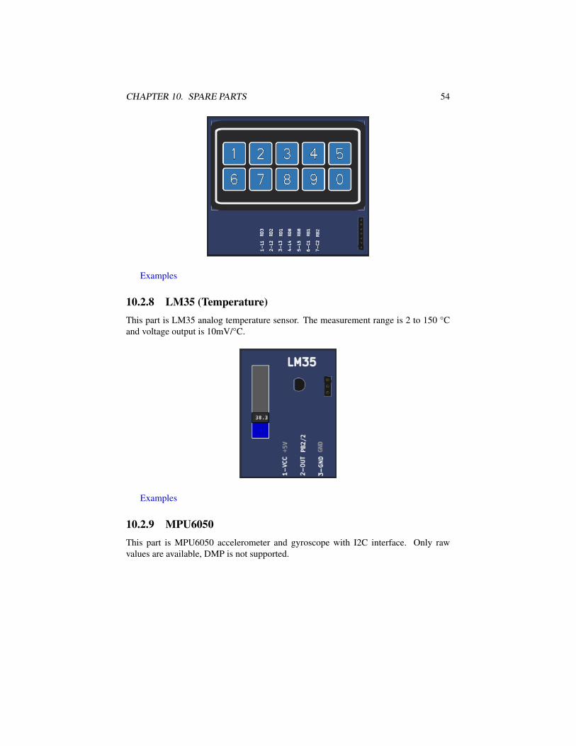
10.2.8 LM35 (Temperature)This part is LM35 analog temperature sensor. The measurement range is 2 to 150 °Cand voltage output is 10mV/°C.
Examples
10.2.9 MPU6050This part is MPU6050 accelerometer and gyroscope with I2C interface. Only rawvalues are available, DMP is not supported.

CHAPTER 10. SPARE PARTS 55
Examples
10.2.10 PotentiometersThis part is formed by 4 potentiometers connected between 0 and 5 volts, the output isconnected to the cursor and varies within this voltage range.

CHAPTER 10. SPARE PARTS 56
Examples
10.2.11 Potentiometers (Rotary)This part is formed by 4 rotary potentiometers connected between 0 and 5 volts, theoutput is connected to the cursor and varies within this voltage range.
Examples
10.2.12 Push ButtonsThis part consists of 8 push buttons. The output active state can be configurable.

CHAPTER 10. SPARE PARTS 57
Examples
10.2.13 Push Buttons (Analogic)This part consists of 8 push buttons connected in a resistive ladder.
Examples
10.2.14 SHT3X (Temp. Hum.)This part is SHT3X analog temperature and humidity sensor. The temperature range is-40 to 125 °C and voltage output is 22.85mV/°C + 1.53V . The relative humidity rangeis 0 to 100 % and voltage output is 40mV/% + 500mV.
Examples
CHAPTER 10. SPARE PARTS 58
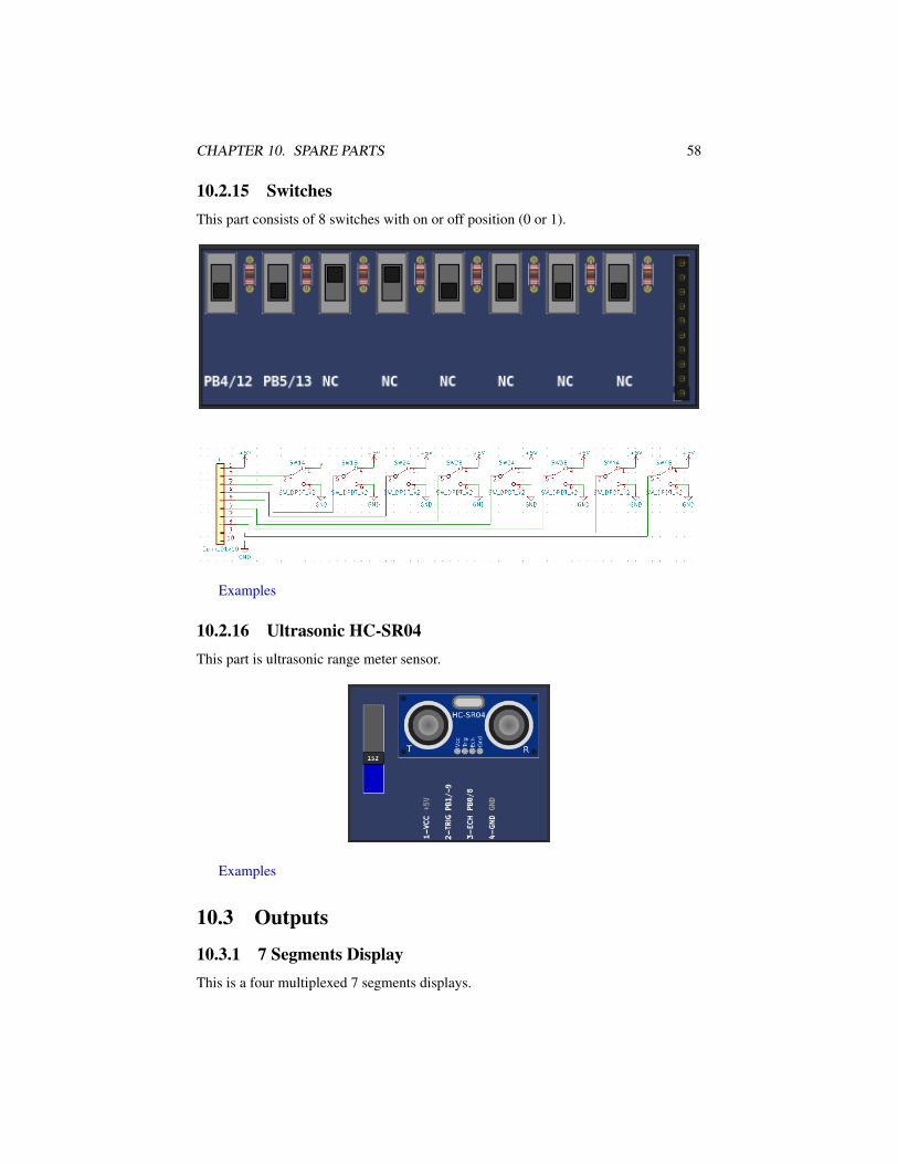
10.2.15 SwitchesThis part consists of 8 switches with on or off position (0 or 1).
Examples
10.2.16 Ultrasonic HC-SR04This part is ultrasonic range meter sensor.
Examples
10.3 Outputs
10.3.1 7 Segments DisplayThis is a four multiplexed 7 segments displays.

CHAPTER 10. SPARE PARTS 59
Examples
10.3.2 7 Segments Display (Decoder)This is a four multiplexed 7 segments displays with BCD to 7 segments decoder (CD4511).
Examples

CHAPTER 10. SPARE PARTS 60
10.3.3 BuzzerThis is a active/passive buzzer. The buzzer has 3 operating modes:
• Active: When powered, the buzzer emits a frequency of 440Hz.
• Passive: In this mode the values read from the input pin are sent directly to thesound card, this mode only works well if the simulation is in real time.
• Tone: This second passive mode measures the frequency on the input and up-dates the frequency of the buzzer every 100ms, its accuracy is less than the nor-mal passive mode but it works better when the simulation is not in real time.
Examples
10.3.4 DC MotorThis part is DC motor with H-bridge driver and quadrature encoder.
Examples
10.3.5 LCD hd44780This part is a text display with 2 (or 4) lines by 16 (or 20) columns.

CHAPTER 10. SPARE PARTS 61

CHAPTER 10. SPARE PARTS 62
Examples
10.3.6 LCD ili9341This part is a color graphic display with 240x320 pixels with touchscreen (xpt2046controller). Only 4 SPI mode and 8 bits parallel mode is avaliable.

CHAPTER 10. SPARE PARTS 63
Examples
10.3.7 LCD pcf8833This part is a color graphic display with 132x132 pixels.
Examples
10.3.8 LCD pcd8544This part is a monochrome graphic display with 48x84 pixels. (Nokia 5110)
Examples
10.3.9 LCD ssd1306This part is a monochrome oled graphic display with 128x64 pixels. The part suportI2C and 4 SPI serial mode.

CHAPTER 10. SPARE PARTS 64
Examples
10.3.10 LED MatrixIt is a 8x8 LED matrix with MAX72xx controller.
Examples
10.3.11 LEDsThis part is a bar of 8 independent red LEDs.

CHAPTER 10. SPARE PARTS 65
Examples
10.3.12 RGB LEDThis part consists of a 4-pin RGB LED. Each color can be triggered independently.Using PWM it is possible to generate several colors by combining the 3 primary colors.
Examples

CHAPTER 10. SPARE PARTS 66
10.3.13 Servo MotorThe servo motor is a component that must be activated with a pulse of variable widthfrom 1ms to 2ms every 20 ms. A pulse of 1ms positions the servo at -90º, one from1.5ms to 0º and one from 2ms to 90º.
Examples
10.3.14 Step MotorThe stepper motor is a component with 4 coils that must be driven in the correct orderto rotate the rotor. Each step of the motor is 1.8º.

CHAPTER 10. SPARE PARTS 67
Examples
10.4 Others
10.4.1 ETH w5500This part is a ethernet shield w5500 with support to 8 sockets simultaneously.
Only TCP/UDP unicast address sockets is supported. DHCP is emulated and returna fake ipv4 address.
All listening ports below 2000 are increased by 2000 to avoid operational systemservices ports. For example listening on port 80 becomes 2080.

CHAPTER 10. SPARE PARTS 68
w5500 Status Legend:
1º Letter - Type 2º Letter - Status 3º Letter - ErrorC - Closed C - Closed B - BindT - TCP I - Initialized S - SendU - UDP L - Listen R - ReceiveM - MACRAW (don’t supported) S - Syn sent L - Listen
E - Established U - ReuseW - Close wait C - ConnectingU - UDP D - ShutdownM - MACRAW (don’t supported)
Click on connector to toggle link status.
Examples
10.4.2 IO 74xx595This is one 74xx595 serial input and parallel output 8 bit shift register.
Examples

CHAPTER 10. SPARE PARTS 69
10.4.3 IO MCP23S17It is a MCP23S17 serial SPI IO expander part.
Examples
10.4.4 IO PCF8574It is a PCF8574 serial I2C IO expander.
Examples
10.4.5 IO UARTThis part is a UART serial port. This part connects the hardware/software UART IOpins of microcontroller to one real/virtual PC serial port. To use virtual port is needto install a virtual port software, as described in 6. The serial communication uses the8N1 format.

CHAPTER 10. SPARE PARTS 70
Examples
10.4.6 Jumper WiresThis part are formed by sixteen jumper wires. Each jumper has one input and oneoutput. The jumper input must be connected to one pin output, the jumper output canbe connected to multiple pin inputs. The jumper can be used to connect microcontrollerpins or make connection between spare parts pins.
Examples
10.4.7 MEM 24CXXXIt is a 24CXXX serial I2C EEPROM part. There are support to the models 24C04 and24C512.

CHAPTER 10. SPARE PARTS 71
Examples
10.4.8 RTC ds1307This part is a ds1307 real time clock with serial I2C interface.
Examples
10.4.9 RTC pfc8563This part is a pfc8563 real time clock with serial I2C interface.

CHAPTER 10. SPARE PARTS 72
Examples
10.4.10 SD CardThis part is a SD Card shield. It’s necessary set one sd card file image before use it.(Click on SD card connector to open file dialog)
On Linux one empty image can be created with this command:
dd if=/dev/zero of=sd.img bs=1M count=32
This empty image can be used with raw sd card access, to work with FAT file systemthe image need to be formatted before the use. (using SdFormatter.ino for example)
Examples
10.4.11 Temperature SystemThis part is a temperature control system. The temperature control system consists ofa heating resistor, an LM35 temperature sensor, a cooler and an infrared tachometer.
CHAPTER 10. SPARE PARTS 73
Examples
10.5 Virtual
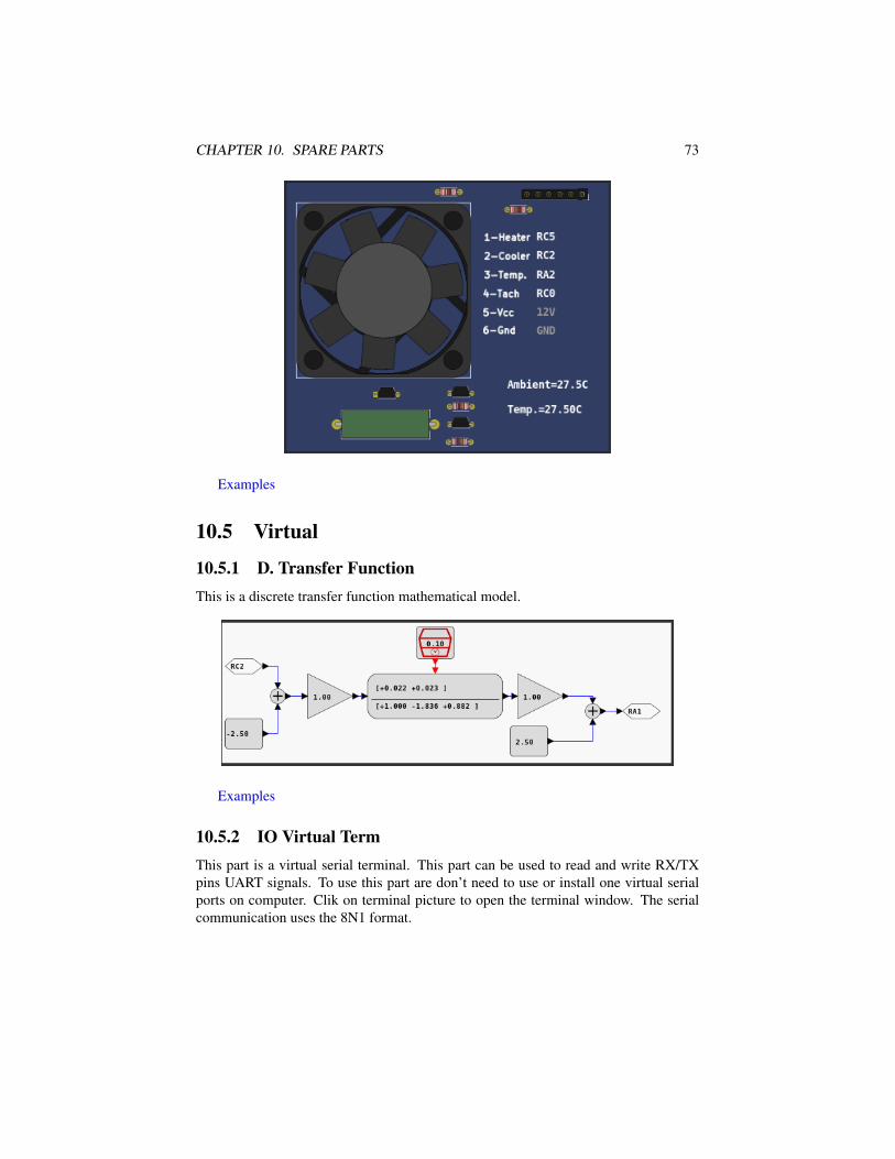
10.5.1 D. Transfer FunctionThis is a discrete transfer function mathematical model.
Examples
10.5.2 IO Virtual TermThis part is a virtual serial terminal. This part can be used to read and write RX/TXpins UART signals. To use this part are don’t need to use or install one virtual serialports on computer. Clik on terminal picture to open the terminal window. The serialcommunication uses the 8N1 format.

CHAPTER 10. SPARE PARTS 74
Examples
10.5.3 Signal GeneratorThis part is a virtual signal generator with support for sine, square and triangular wavesgeneration with amplitude and frequency adjustment.
Examples
10.5.4 VCD DumpThis part is a digital value file dump recorder. The file can be visualized with gtkwave.

CHAPTER 10. SPARE PARTS 75
Examples
10.5.5 VCD Dump (Analogic)This part is a analog value file dump recorder. The file can be visualized with gtkwave.
Examples
10.5.6 VCD PlayThis part play a VCD file saved from VCD Dump part.

CHAPTER 10. SPARE PARTS 76
Examples

Chapter 11
Troubleshooting
The simulation in PICSimLab consists of 3 parts:
• The microcontroller program
• Microcontroller simulation (made by picsim and simavr)
• Simulation of boards and parts
When a problem occurs it is important to detect where it is occurring.One of the most common problems is the error in the microcontroller program.
Before creating an issue, test your code on a real circuit (even partially) to make surethe problem is not there.
Errors in the microcontroller simulation can be detected using code debugging.Any instruction execution or peripheral behavior outside the expected should be re-ported in the project of simulator used (picsim or simavr).
If the problem is not in either of the previous two options, the problem is probablyin PICSimLab. A good practice is to send a source code together with a PICSimLabworkspace (.pzw file) to open the issue about the problem.
77

Chapter 12
License
Copyright © 2021 Luis Claudio Gambôa Lopes <[email protected]>This program is free software; you can redistribute it and/or modify it under the
terms of the GNU General Public License as published by the Free Software Founda-tion; either version 2 of the License, or (at your option) any later version.
This program is distributed in the hope that it will be useful, but WITHOUT ANYWARRANTY; without even the implied warranty of MERCHANTABILITY or FIT-NESS FOR A PARTICULAR PURPOSE. See the GNU General Public License formore details.
You should have received a copy of the GNU General Public License along withthis program; if not, write to the Free Software Foundation, Inc., 59 Temple Place,Suite 330, Boston, MA 02111-1307, USA.
78

Appendix A
Online Simulator
The online version of PICSimLab has the same source code as the desktop versioncompiled using Emscripten. The online version does not have the Tools menu, supportfor debugging and serial communication (only for IO Vterm).
There are three versions generated with Emscripten:
• WASM with multithread - Fast speed (50% of desktop version ) and worsebrowser compatibility (currently only work in Chrome desktop and Firefox nightlydesktop because javascript SharedArrayBuffer security requirements)
79
APPENDIX A. ONLINE SIMULATOR 80
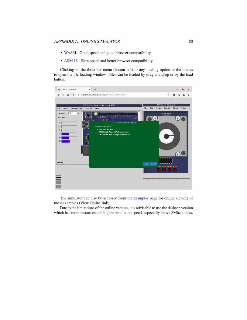
• WASM - Good speed and good browser compatibility
• ASM.JS - Slow speed and better browser compatibility
Clicking on the three-bar menu (botton left) or any loading option in the menusto open the file loading window. Files can be loaded by drag and drop or by the loadbutton.
The simulator can also be accessed from the examples page for online viewing ofmost examples (View Online link).
Due to the limitations of the online version, it is advisable to use the desktop versionwhich has more resources and higher simulation speed, especially above 8Mhz clocks.
Appendix B
Use with MPLABX
Use with MPLABX to program and Debug
B.1 Installing the Necessary Tools
B.1.1 Install MPLABX IDE and XC8 CompilerLinks for download MPLABX IDE and XC8 Compiler installers. Download and in-stall.
For PICSimLab only MPLAB X IDE and 8 bit MCU support needs to be installed.
81

APPENDIX B. USE WITH MPLABX 82
B.1.2 Install PICsimLabLink for download PICSimLab installer. Download and install
B.1.3 How to Install PICSimLab MPLABX Debugger pluginLink for download PicsimLab MPLABX Debugger plugin (com-picsim-picsimlab.nbm)

APPENDIX B. USE WITH MPLABX 83

APPENDIX B. USE WITH MPLABX 84

APPENDIX B. USE WITH MPLABX 85

APPENDIX B. USE WITH MPLABX 86

APPENDIX B. USE WITH MPLABX 87
B.2 Configuring a New Project in MPLABX
B.2.1 Project Creation

APPENDIX B. USE WITH MPLABX 88

APPENDIX B. USE WITH MPLABX 89

APPENDIX B. USE WITH MPLABX 90
B.2.2 File Creation

APPENDIX B. USE WITH MPLABX 91
B.2.3 PIC Configuration Bits

APPENDIX B. USE WITH MPLABX 92
B.2.4 Code ExamplePaste the configuration and this simple code example in test.c:
void main(){
TRISB=0x00; //All pins as outputPORTB=0; //All pins offwhile(1) //main loop{
PORTBbits.RB0=1; //Turn RB0 onPORTBbits.RB1=1; //Turn RB1 onPORTB=0; //All pins off
}}

APPENDIX B. USE WITH MPLABX 93
B.2.5 Building the ProjectUse the Build button and wait for the message “BUILD SUCCESSFUL”.

APPENDIX B. USE WITH MPLABX 94
B.3 Program and Debug PICsimLab With MPLABX
B.3.1 Starting PICsimLab
The plugin connect to Picsimlab through a TCP socket using port 1234, and you haveto allow the access in the firewall. Verify in the PICsimLab statusbar the message“MplabxD: Ok”. It’s show debugger server state.
B.3.2 Programming PICsimLabUse the Debug button to programming PICsimLab.

APPENDIX B. USE WITH MPLABX 95
B.3.3 Pausing the ProgramUse the Pause button to stop the program and inspect the code and memory.
B.3.4 Restarting the ProgramUse the Restart button to restart the program.

APPENDIX B. USE WITH MPLABX 96
B.3.5 Running Step by StepUse the Step or Step Over button to run the program step by step.
See in the PICsimLab the changes of each step.

APPENDIX B. USE WITH MPLABX 97
B.3.6 Stopping DebuggerUse the Stop button to turn off the MPLABX debugger.
B.3.7 Disconnect DebuggerUse the menu Debug->Disconnect From Debug Tool to disconnect the MPLABXdebugger. The program continues running in PICsimLab after MPLABX debugger isdisconnected.

APPENDIX B. USE WITH MPLABX 98
B.4 This Tutorial in VideoLink for Youtube video version of this tutorial: How to use MPLABX to program anddebug PicsimLab 0.6

Appendix C
Creating New Boards
First get the source code and compile as described in Install from source.
C.1 Creating a New BoardThe first step is get the schematic and all information about the board hardware. Thesecond step is the creation of four files in PICSimLab dir (consider replace the ’x’ ofboard_x for a name of your board in your case):
• Board Picture (share/boards/X/board.svg) or (share/boards/X/board.png);
• Board map (share/boards/X/board.map);
• Board header (src/boards/board_x.h);
• Board C++ code (src/boards/board_x.cc);
The third and last step is recompiling PICSimLab with new board support.
C.1.1 Board Hardware and SchematicFor this tutorial, the board created have the hardware shown in diagram below:
ICSP
PIC
Serial
LED Output
Switch Input
Analog Input
99

APPENDIX C. CREATING NEW BOARDS 100
The schematic for the tutorial board made in Kicad.

APPENDIX C. CREATING NEW BOARDS 101
And the PCB layout was made in Kicad too. The PCB is not necessary if you havea real board.
APPENDIX C. CREATING NEW BOARDS 102
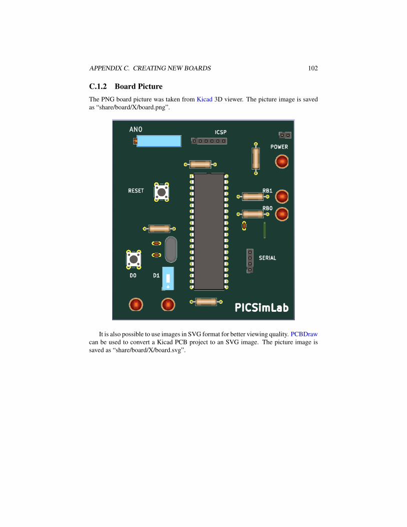
C.1.2 Board PictureThe PNG board picture was taken from Kicad 3D viewer. The picture image is savedas “share/board/X/board.png”.
It is also possible to use images in SVG format for better viewing quality. PCBDrawcan be used to convert a Kicad PCB project to an SVG image. The picture image issaved as “share/board/X/board.svg”.

APPENDIX C. CREATING NEW BOARDS 103

APPENDIX C. CREATING NEW BOARDS 104
C.1.3 Picture mapThe PICSimLab use one picture image map for inputs and outputs.
The inputs are the areas in board picture which user can interact (by mouse click)and start with letters “I_”.
The output are the areas in board picture to be redraw according simulator statusand start with letters “O_”.
The bidirectional areas in board picture which user can interact and need to beredraw according simulator status are started with letter “B_”.
The picture map used for PICSimLab are normal HTML image-map. They canbe made by hand or using any software which can handle image maps. The originalPICSimLab maps are made using Gimp image editor.
To start, in the GIMP, use the Filters->Web->Image Map to open image map editorwindow.

APPENDIX C. CREATING NEW BOARDS 105
Then select rectangle or circle map on toolbar.
And mark the area in picture.
APPENDIX C. CREATING NEW BOARDS 106
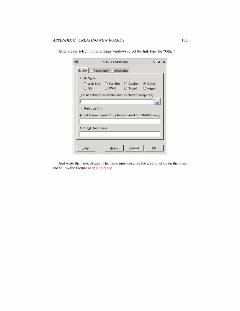
After area is select, in the settings windows select the link type for “Other”.
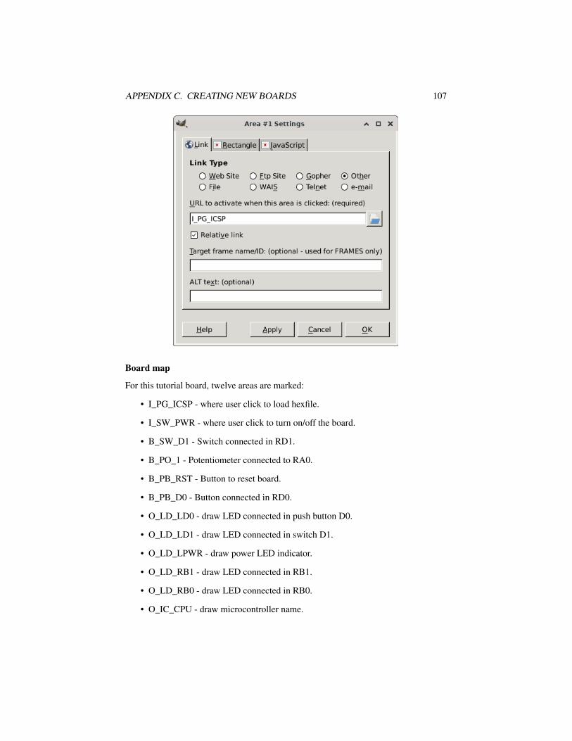
And write the name of area. The name must describe the area function on the boardand follow the Picture Map Reference.
APPENDIX C. CREATING NEW BOARDS 107
Board map
For this tutorial board, twelve areas are marked:
• I_PG_ICSP - where user click to load hexfile.
• I_SW_PWR - where user click to turn on/off the board.
• B_SW_D1 - Switch connected in RD1.
• B_PO_1 - Potentiometer connected to RA0.
• B_PB_RST - Button to reset board.
• B_PB_D0 - Button connected in RD0.
• O_LD_LD0 - draw LED connected in push button D0.
• O_LD_LD1 - draw LED connected in switch D1.
• O_LD_LPWR - draw power LED indicator.
• O_LD_RB1 - draw LED connected in RB1.
• O_LD_RB0 - draw LED connected in RB0.
• O_IC_CPU - draw microcontroller name.

APPENDIX C. CREATING NEW BOARDS 108
Board map generated by Gimp image map editor and saved as “share/boards/X/board.map”.
1 <img src="[board_x] (imported)" width="448" height="491" border="0" usemap="#map" />
2
3 <map name="map">
4 <!-- #$-:Image map file created by GIMP Image Map plug-in -->
5 <!-- #$-:GIMP Image Map plug-in by Maurits Rijk -->
6 <!-- #$-:Please do not edit lines starting with "#$" -->
7 <!-- #$VERSION:2.3 -->
8 <!-- #$AUTHOR:[email protected] -->
9 <area shape="rect" coords="196,45,280,58" href="I_PG_ICSP" />
10 <area shape="rect" coords="409,30,441,46" href="I_SW_PWR" />
11 <area shape="rect" coords="133,379,142,401" href="B_SW_D1" />
12 <area shape="rect" coords="74,42,156,61" href="B_PO_1" />
13 <area shape="rect" coords="105,162,138,195" href="B_PB_RST" />
14 <area shape="rect" coords="37,327,70,360" href="B_PB_D0" />
15 <area shape="circle" coords="59,454,17" href="O_LD_LD0" />
16 <area shape="circle" coords="137,454,17" href="O_LD_LD1" />
17 <area shape="circle" coords="418,102,17" href="O_LD_LPWR" />
18 <area shape="circle" coords="418,189,17" href="O_LD_RB1" />
19 <area shape="circle" coords="418,232,17" href="O_LD_RB0" />
20 <area shape="rect" coords="227,220,247,328" href="O_IC_CPU" />
21 </map>
The kicad project files can be download from github PICSimLab repository.
C.1.4 Board codeThe header file and c++ code file with comments are listed in the next two subsections.This files control the behavior of board in simulator.

APPENDIX C. CREATING NEW BOARDS 109
board_x.h
board_x.h online file.board_x.h online doxygen version.
1 /* ########################################################################
2
3 PICsimLab - PIC laboratory simulator
4
5 ########################################################################
6
7 Copyright (c) : 2015-2021 Luis Claudio Gambôa Lopes
8
9 This program is free software; you can redistribute it and/or modify
10 it under the terms of the GNU General Public License as published by
11 the Free Software Foundation; either version 2, or (at your option)
12 any later version.
13
14 This program is distributed in the hope that it will be useful,
15 but WITHOUT ANY WARRANTY; without even the implied warranty of
16 MERCHANTABILITY or FITNESS FOR A PARTICULAR PURPOSE. See the
17 GNU General Public License for more details.
18
19 You should have received a copy of the GNU General Public License
20 along with this program; if not, write to the Free Software
21 Foundation, Inc., 675 Mass Ave, Cambridge, MA 02139, USA.
22
23 For e-mail suggestions : [email protected]
24 ######################################################################## */
25
26 #ifndef BOARD_x_H
27 #define BOARD_x_H
28
29 #include<lxrad.h>
30
31 #include "bsim_picsim.h"
32
33 #define BOARD_x_Name "X"
34
35 //new board class must be derived from board class defined in board.h
36 class cboard_x:public bsim_picsim
37 {
38 private:
39 unsigned char p_BT1; //first board push button in RD0
40 unsigned char p_BT2; //second board switch in RD1
41
42 //value of potentiometer
43 unsigned char pot1;

APPENDIX C. CREATING NEW BOARDS 110
44 //flag to control if potentiometer is active
45 unsigned char active;
46
47 //controls to be added in simulator window
48 CGauge *gauge1; //gauge to show mean value of RB0
49 CGauge *gauge2; //gauge to show mean value of RB1
50 CLabel *label2; //label of gauge RB0
51 CLabel *label3; //label of gauge RB1
52
53 //Register controls for remote interface called once on board creation
54 void RegisterRemoteControl(void);
55
56 lxColor color1;//LEDs color 1
57 lxColor color2;//LEDs color 2
58 lxFont font;
59 public:
60 //Constructor called once on board creation
61 cboard_x(void);
62 //Destructor called once on board destruction
63 ~cboard_x(void);
64 //Return the board name
65 lxString GetName(void) {return lxT(BOARD_x_Name); };
66 //Return the about info of board
67 lxString GetAboutInfo(void){return lxT("L.C. Gamboa \n <[email protected]>");};
68 //Called ever 100ms to draw board
69 void Draw(CDraw *draw);
70 void Run_CPU(void);
71 //Return a list of board supported microcontrollers
72 lxString GetSupportedDevices(void){return lxT("PIC16F877A,PIC18F4550,PIC18F4620,");};
73 //Reset board status
74 void Reset(void);
75 //Event on the board
76 void EvMouseButtonPress(uint button, uint x, uint y,uint state);
77 //Event on the board
78 void EvMouseButtonRelease(uint button, uint x, uint y,uint state);
79 //Event on the board
80 void EvMouseMove(uint button, uint x, uint y, uint state);
81 //Event on the board
82 void EvKeyPress(uint key,uint mask);
83 //Event on the board
84 void EvKeyRelease(uint key,uint mask);
85 //Called ever 1s to refresh status
86 void RefreshStatus(void);
87 //Called to save board preferences in configuration file
88 void WritePreferences(void);
89 //Called whe configuration file load preferences
90 void ReadPreferences(char *name,char *value);

APPENDIX C. CREATING NEW BOARDS 111
91 //return the input ids numbers of names used in input map
92 unsigned short get_in_id(char * name);
93 //return the output ids numbers of names used in output map
94 unsigned short get_out_id(char * name);
95 };
96
97 #endif /* BOARD_x_H */
APPENDIX C. CREATING NEW BOARDS 112
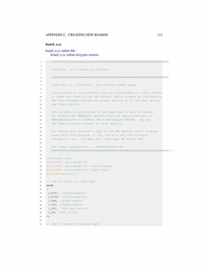
board_x.cc
board_x.cc online file.board_x.cc online doxygen version.
1 /* ########################################################################
2
3 PICsimLab - PIC laboratory simulator
4
5 ########################################################################
6
7 Copyright (c) : 2015-2021 Luis Claudio Gambôa Lopes
8
9 This program is free software; you can redistribute it and/or modify
10 it under the terms of the GNU General Public License as published by
11 the Free Software Foundation; either version 2, or (at your option)
12 any later version.
13
14 This program is distributed in the hope that it will be useful,
15 but WITHOUT ANY WARRANTY; without even the implied warranty of
16 MERCHANTABILITY or FITNESS FOR A PARTICULAR PURPOSE. See the
17 GNU General Public License for more details.
18
19 You should have received a copy of the GNU General Public License
20 along with this program; if not, write to the Free Software
21 Foundation, Inc., 675 Mass Ave, Cambridge, MA 02139, USA.
22
23 For e-mail suggestions : [email protected]
24 ######################################################################## */
25
26 //include files
27 #include"../picsimlab1.h"
28 #include"../picsimlab4.h" //Oscilloscope
29 #include"../picsimlab5.h" //Spare Parts
30 #include"board_x.h"
31
32 /* ids of inputs of input map*/
33 enum
34 {
35 I_POT1, //potentiometer
36 I_ICSP, //ICSP connector
37 I_PWR, //Power button
38 I_RST, //Reset button
39 I_BD0, //RD0 push button
40 I_SD1 //RD1 switch
41 };
42
43 /* ids of outputs of output map*/

APPENDIX C. CREATING NEW BOARDS 113
44 enum
45 {
46 O_POT1, //potentiometer
47 O_RST, //Reset button
48 O_SD1, //switch position (On/Off)
49 O_LD0, //LED on RD0 push button
50 O_LD1, //LED on RD1 switch
51 O_LPWR, //Power LED
52 O_RB0, //LED on RB0 output
53 O_RB1, //LED on RB1 output
54 O_BD0, //RD1 switch
55 O_CPU //CPU name
56 };
57
58 //return the input ids numbers of names used in input map
59
60 unsigned short
61 cboard_x::get_in_id(char * name)
62 {
63 if (strcmp (name, "PG_ICSP") == 0)return I_ICSP;
64 if (strcmp (name, "SW_PWR") == 0)return I_PWR;
65 if (strcmp (name, "PB_RST") == 0)return I_RST;
66 if (strcmp (name, "PB_D0") == 0)return I_BD0;
67 if (strcmp (name, "SW_D1") == 0)return I_SD1;
68 if (strcmp (name, "PO_1") == 0)return I_POT1;
69
70 printf ("Error input '%s' don't have a valid id! \n", name);
71 return -1;
72 }
73
74 //return the output ids numbers of names used in output map
75
76 unsigned short
77 cboard_x::get_out_id(char * name)
78 {
79
80 if (strcmp (name, "SW_D1") == 0)return O_SD1;
81 if (strcmp (name, "LD_LD0") == 0)return O_LD0;
82 if (strcmp (name, "LD_LD1") == 0)return O_LD1;
83 if (strcmp (name, "LD_LPWR") == 0)return O_LPWR;
84 if (strcmp (name, "LD_RB1") == 0)return O_RB1;
85 if (strcmp (name, "LD_RB0") == 0)return O_RB0;
86 if (strcmp (name, "PB_D0") == 0)return O_BD0;
87 if (strcmp (name, "PO_1") == 0)return O_POT1;
88 if (strcmp (name, "PB_RST") == 0)return O_RST;
89 if (strcmp (name, "IC_CPU") == 0)return O_CPU;
90
91 printf ("Error output '%s' don't have a valid id! \n", name);

APPENDIX C. CREATING NEW BOARDS 114
92 return 1;
93 }
94
95 //Constructor called once on board creation
96
97 cboard_x::cboard_x(void) :
98 font(10, lxFONTFAMILY_TELETYPE, lxFONTSTYLE_NORMAL, lxFONTWEIGHT_BOLD)
99 {
100 Proc = "PIC18F4550"; //default microcontroller if none defined in preferences
101 ReadMaps (); //Read input and output board maps
102
103 pot1 = 100;
104
105 active = 0;
106
107 //controls properties and creation
108 //gauge1
109 gauge1 = new CGauge ();
110 gauge1->SetFOwner (&Window1);
111 gauge1->SetName (lxT ("gauge1_px"));
112 gauge1->SetX (13);
113 gauge1->SetY (382 - 160);
114 gauge1->SetWidth (140);
115 gauge1->SetHeight (20);
116 gauge1->SetEnable (1);
117 gauge1->SetVisible (1);
118 gauge1->SetRange (100);
119 gauge1->SetValue (0);
120 gauge1->SetType (4);
121 Window1.CreateChild (gauge1);
122 //gauge2
123 gauge2 = new CGauge ();
124 gauge2->SetFOwner (&Window1);
125 gauge2->SetName (lxT ("gauge2_px"));
126 gauge2->SetX (12);
127 gauge2->SetY (330 - 160);
128 gauge2->SetWidth (140);
129 gauge2->SetHeight (20);
130 gauge2->SetEnable (1);
131 gauge2->SetVisible (1);
132 gauge2->SetRange (100);
133 gauge2->SetValue (0);
134 gauge2->SetType (4);
135 Window1.CreateChild (gauge2);
136 //label2
137 label2 = new CLabel ();
138 label2->SetFOwner (&Window1);

APPENDIX C. CREATING NEW BOARDS 115
139 label2->SetName (lxT ("label2_px"));
140 label2->SetX (12);
141 label2->SetY (306 - 160);
142 label2->SetWidth (60);
143 label2->SetHeight (20);
144 label2->SetEnable (1);
145 label2->SetVisible (1);
146 label2->SetText (lxT ("RB0"));
147 label2->SetAlign (1);
148 Window1.CreateChild (label2);
149 //label3
150 label3 = new CLabel ();
151 label3->SetFOwner (&Window1);
152 label3->SetName (lxT ("label3_px"));
153 label3->SetX (13);
154 label3->SetY (357 - 160);
155 label3->SetWidth (60);
156 label3->SetHeight (20);
157 label3->SetEnable (1);
158 label3->SetVisible (1);
159 label3->SetText (lxT ("RB1"));
160 label3->SetAlign (1);
161 Window1.CreateChild (label3);
162 }
163
164 //Destructor called once on board destruction
165
166 cboard_x::~cboard_x(void)
167 {
168 //controls destruction
169 Window1.DestroyChild (gauge1);
170 Window1.DestroyChild (gauge2);
171 Window1.DestroyChild (label2);
172 Window1.DestroyChild (label3);
173 }
174
175 //Reset board status
176
177 void
178 cboard_x::Reset(void)
179 {
180 pic_reset (1);
181
182 p_BT1 = 1; //set push button in default state (high)
183
184 //write button state to pic pin 19 (RD0)
185 pic_set_pin (19, p_BT1);

APPENDIX C. CREATING NEW BOARDS 116
186 //write switch state to pic pin 20 (RD1)
187 pic_set_pin (20, p_BT2);
188
189
190 //verify serial port state and refresh status bar
191 #ifndef _WIN_
192 if (pic.serial[0].serialfd > 0)
193 #else
194 if (pic.serial[0].serialfd != INVALID_HANDLE_VALUE)
195 #endif
196 Window1.statusbar1.SetField (2, lxT ("Serial: ") +
197 lxString::FromAscii (SERIALDEVICE) + lxT (":") + itoa (pic.serial[0].serialbaud) + lxT ("(") +
198 lxString ().Format ("%4.1f", fabs ((100.0 * pic.serial[0].serialexbaud - 100.0 *199 pic.serial[0].serialbaud) / pic.serial[0].serialexbaud)) + lxT ("%)"));
200 else
201 Window1.statusbar1.SetField (2, lxT ("Serial: ") +
202 lxString::FromAscii (SERIALDEVICE) + lxT (" (ERROR)"));
203
204 if (use_spare)Window5.Reset ();
205
206 RegisterRemoteControl ();
207 }
208
209 //Register variables to be controled by remote control
210
211 void
212 cboard_x::RegisterRemoteControl(void)
213 {
214 //register inputa
215 input_ids[I_BD0]->status = &p_BT1;
216 input_ids[I_SD1]->status = &p_BT2;
217 input_ids[I_POT1]->status = &pot1;
218
219 //register output to be updated on input change
220 input_ids[I_BD0]->update = &output_ids[O_BD0]->update;
221 input_ids[I_SD1]->update = &output_ids[O_SD1]->update;
222 input_ids[I_POT1]->update = &output_ids[O_POT1]->update;
223
224 //register outputa
225 output_ids[O_RB0]->status = &pic.pins[32].oavalue;
226 output_ids[O_RB1]->status = &pic.pins[33].oavalue;
227 output_ids[O_LD0]->status = &pic.pins[18].oavalue;
228 output_ids[O_LD1]->status = &pic.pins[19].oavalue;
229 }
230
231 //Called ever 1s to refresh status
232

APPENDIX C. CREATING NEW BOARDS 117
233 void
234 cboard_x::RefreshStatus(void)
235 {
236 //verify serial port state and refresh status bar
237 #ifndef _WIN_
238 if (pic.serial[0].serialfd > 0)
239 #else
240 if (pic.serial[0].serialfd != INVALID_HANDLE_VALUE)
241 #endif
242 Window1.statusbar1.SetField (2, lxT ("Serial: ") +
243 lxString::FromAscii (SERIALDEVICE) + lxT (":") + itoa (pic.serial[0].serialbaud) + lxT ("(") +
244 lxString ().Format ("%4.1f", fabs ((100.0 * pic.serial[0].serialexbaud - 100.0 *245 pic.serial[0].serialbaud) / pic.serial[0].serialexbaud)) + lxT ("%)"));
246 else
247 Window1.statusbar1.SetField (2, lxT ("Serial: ") +
248 lxString::FromAscii (SERIALDEVICE) + lxT (" (ERROR)"));
249
250 }
251
252 //Called to save board preferences in configuration file
253
254 void
255 cboard_x::WritePreferences(void)
256 {
257 //write selected microcontroller of board_x to preferences
258 Window1.saveprefs (lxT ("X_proc"), Proc);
259 //write switch state of board_x to preferences
260 Window1.saveprefs (lxT ("X_bt2"), lxString ().Format ("%i", p_BT2));
261 //write microcontroller clock to preferences
262 Window1.saveprefs (lxT ("X_clock"), lxString ().Format ("%2.1f", Window1.GetClock ()));
263 //write potentiometer position to preferences
264 Window1.saveprefs (lxT ("X_pot1"), lxString ().Format ("%i", pot1));
265 }
266
267 //Called whe configuration file load preferences
268
269 void
270 cboard_x::ReadPreferences(char *name, char *value)
271 {
272 //read switch state of board_x of preferences
273 if (!strcmp (name, "X_bt2"))
274 {
275 if (value[0] == '0')
276 p_BT2 = 0;
277 else
278 p_BT2 = 1;
279 }

APPENDIX C. CREATING NEW BOARDS 118
280 //read microcontroller of preferences
281 if (!strcmp (name, "X_proc"))
282 {
283 Proc = value;
284 }
285 //read microcontroller clock
286 if (!strcmp (name, "X_clock"))
287 {
288 Window1.SetClock (atof (value));
289 }
290
291 //read potentiometer position
292 if (!strcmp (name, "X_pot1"))
293 {
294 pot1 = atoi (value);
295 }
296 }
297
298
299 //Event on the board
300
301 void
302 cboard_x::EvKeyPress(uint key, uint mask)
303 {
304 //if keyboard key 1 is pressed then activate button (state=0)
305 if (key == '1')
306 {
307 p_BT1 = 0;
308 output_ids[O_BD0]->update = 1;
309 }
310
311 //if keyboard key 2 is pressed then toggle switch state
312 if (key == '2')
313 {
314 p_BT2 ^= 1;
315 output_ids[O_SD1]->update = 1;
316 }
317
318 }
319
320 //Event on the board
321
322 void
323 cboard_x::EvKeyRelease(uint key, uint mask)
324 {
325 //if keyboard key 1 is pressed then deactivate button (state=1)
326 if (key == '1')

APPENDIX C. CREATING NEW BOARDS 119
327 {
328 p_BT1 = 1;
329 output_ids[O_BD0]->update = 1;
330 }
331
332 }
333
334 //Event on the board
335
336 void
337 cboard_x::EvMouseButtonPress(uint button, uint x, uint y, uint state)
338 {
339
340 int i;
341
342 //search for the input area which owner the event
343 for (i = 0; i < inputc; i++)
344 {
345 if (((input[i].x1 <= x)&&(input[i].x2 >= x))&&((input[i].y1 <= y)&&
346 (input[i].y2 >= y)))
347 {
348
349 switch (input[i].id)
350 {
351 //if event is over I_ISCP area then load hex file
352 case I_ICSP:
353 Window1.menu1_File_LoadHex_EvMenuActive (NULL);
354 break;
355 //if event is over I_PWR area then toggle board on/off
356 case I_PWR:
357 if (Window1.Get_mcupwr ()) //if on turn off
358 {
359 Window1.Set_mcurun (0);
360 Window1.Set_mcupwr (0);
361 Reset ();
362 p_BT1 = 1;
363 Window1.statusbar1.SetField (0, lxT ("Stoped"));
364 }
365 else //if off turn on
366 {
367 Window1.Set_mcupwr (1);
368 Window1.Set_mcurun (1);
369 Reset ();
370 Window1.statusbar1.SetField (0, lxT ("Running..."));
371 }
372 output_ids[O_LPWR]->update = 1;
373 break;
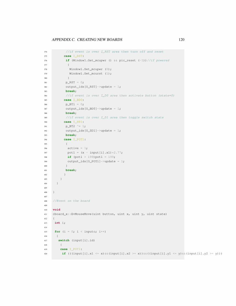
APPENDIX C. CREATING NEW BOARDS 120
374 //if event is over I_RST area then turn off and reset
375 case I_RST:
376 if (Window1.Get_mcupwr () && pic_reset (-1))//if powered
377 {
378 Window1.Set_mcupwr (0);
379 Window1.Set_mcurst (1);
380 }
381 p_RST = 0;
382 output_ids[O_RST]->update = 1;
383 break;
384 //if event is over I_D0 area then activate button (state=0)
385 case I_BD0:
386 p_BT1 = 0;
387 output_ids[O_BD0]->update = 1;
388 break;
389 //if event is over I_D1 area then toggle switch state
390 case I_SD1:
391 p_BT2 ^= 1;
392 output_ids[O_SD1]->update = 1;
393 break;
394 case I_POT1:
395 {
396 active = 1;
397 pot1 = (x - input[i].x1)*2.77;
398 if (pot1 > 199)pot1 = 199;
399 output_ids[O_POT1]->update = 1;
400 }
401 break;
402 }
403 }
404 }
405
406 }
407
408 //Event on the board
409
410 void
411 cboard_x::EvMouseMove(uint button, uint x, uint y, uint state)
412 {
413 int i;
414
415 for (i = 0; i < inputc; i++)
416 {
417 switch (input[i].id)
418 {
419 case I_POT1:
420 if (((input[i].x1 <= x)&&(input[i].x2 >= x))&&((input[i].y1 <= y)&&(input[i].y2 >= y)))

APPENDIX C. CREATING NEW BOARDS 121
421 {
422 if (active)
423 {
424 pot1 = (x - input[i].x1)*2.77;
425 if (pot1 > 199)pot1 = 199;
426 output_ids[O_POT1]->update = 1;
427 }
428 }
429 break;
430 }
431 }
432 }
433
434 //Event on the board
435
436 void
437 cboard_x::EvMouseButtonRelease(uint button, uint x, uint y, uint state)
438 {
439 int i;
440
441 //search for the input area which owner the event
442 for (i = 0; i < inputc; i++)
443 {
444 if (((input[i].x1 <= x)&&(input[i].x2 >= x))&&((input[i].y1 <= y)&&
445 (input[i].y2 >= y)))
446 {
447 switch (input[i].id)
448 {
449 //if event is over I_RST area then turn on
450 case I_RST:
451 if (Window1.Get_mcurst ())//if powered
452 {
453 Window1.Set_mcupwr (1);
454 Window1.Set_mcurst (0);
455
456 if (pic_reset (-1))
457 {
458 Reset ();
459 }
460 }
461 p_RST = 1;
462 output_ids[O_RST]->update = 1;
463 break;
464 //if event is over I_D0 area then deactivate button (state=1)
465 case I_BD0:
466 p_BT1 = 1;
467 output_ids[O_BD0]->update = 1;

APPENDIX C. CREATING NEW BOARDS 122
468 break;
469 case I_POT1:
470 {
471 active = 0;
472 output_ids[O_POT1]->update = 1;
473 }
474 break;
475 }
476 }
477 }
478
479 }
480
481
482 //Called ever 100ms to draw board
483 //This is the critical code for simulator running speed
484
485 void
486 cboard_x::Draw(CDraw *draw)
487 {
488 int update = 0; //verifiy if updated is needed
489 int i;
490
491
492 //board_x draw
493 for (i = 0; i < outputc; i++) //run over all outputs
494 {
495 if (output[i].update)//only if need update
496 {
497 output[i].update = 0;
498
499 if (!update)
500 {
501 draw->Canvas.Init (Scale, Scale);
502 }
503 update++; //set to update buffer
504
505 if (!output[i].r)//if output shape is a rectangle
506 {
507 if (output[i].id == O_SD1)//if output is switch
508 {
509 //draw a background white rectangle
510 draw->Canvas.SetBgColor (255, 255, 255);
511 draw->Canvas.Rectangle (1, output[i].x1, output[i].y1,
512 output[i].x2 - output[i].x1, output[i].y2 - output[i].y1);
513
514 if (!p_BT2) //draw switch off

APPENDIX C. CREATING NEW BOARDS 123
515 {
516 //draw a grey rectangle
517 draw->Canvas.SetBgColor (70, 70, 70);
518 draw->Canvas.Rectangle (1, output[i].x1, output[i].y1 +
519 ((int) ((output[i].y2 - output[i].y1)*0.35)), output[i].x2 - output[i].x1,
520 (int) ((output[i].y2 - output[i].y1)*0.65));
521 }
522 else //draw switch on
523 {
524 //draw a grey rectangle
525 draw->Canvas.SetBgColor (70, 70, 70);
526 draw->Canvas.Rectangle (1, output[i].x1,
527 output[i].y1, output[i].x2 - output[i].x1,
528 (int) ((output[i].y2 - output[i].y1)*0.65));
529 }
530 }
531 else if (output[i].id == O_BD0)
532 {
533 draw->Canvas.SetColor (102, 102, 102);
534 draw->Canvas.Circle (1, output[i].cx, output[i].cy, 10);
535 if (p_BT1)
536 {
537 draw->Canvas.SetColor (15, 15, 15);
538 }
539 else
540 {
541 draw->Canvas.SetColor (55, 55, 55);
542 }
543 draw->Canvas.Circle (1, output[i].cx, output[i].cy, 8);
544 }
545 else if (output[i].id == O_RST)
546 {
547 draw->Canvas.SetColor (102, 102, 102);
548 draw->Canvas.Circle (1, output[i].cx, output[i].cy, 10);
549
550 if (p_RST)
551 {
552 draw->Canvas.SetColor (15, 15, 15);
553 }
554 else
555 {
556 draw->Canvas.SetColor (55, 55, 55);
557 }
558 draw->Canvas.Circle (1, output[i].cx, output[i].cy, 8);
559 }
560 else if (output[i].id == O_POT1)
561 {

APPENDIX C. CREATING NEW BOARDS 124
562 draw->Canvas.SetColor (0, 50, 215);
563 draw->Canvas.Rectangle (1, output[i].x1, output[i].y1, output[i].x2 - output[i].x1, output[i].y2 - output[i].y1);
564 draw->Canvas.SetColor (250, 250, 250);
565 draw->Canvas.Rectangle (1, output[i].x1 + pot1 / 2.77, output[i].y1 + 2, 10, 15);
566 }
567 else if (output[i].id == O_CPU)
568 {
569 draw->Canvas.SetFont (font);
570 int x, y, w, h;
571 draw->Canvas.SetColor (26, 26, 26);
572 draw->Canvas.Rectangle (1, output[i].x1, output[i].y1, output[i].x2 - output[i].x1, output[i].y2 - output[i].y1);
573
574 draw->Canvas.SetColor (230, 230, 230);
575 w = output[i].x2 - output[i].x1;
576 h = output[i].y2 - output[i].y2;
577 x = output[i].x1 + (w / 2) + 7;
578 y = output[i].y1 + (h / 2) + (Proc.length ());
579 draw->Canvas.RotatedText (Proc, x, y, 270);
580 }
581 }
582 else //if output shape is a circle
583 {
584 draw->Canvas.SetFgColor (0, 0, 0); //black
585
586 switch (output[i].id)//search for color of output
587 {
588 case O_LD0: //White using pin 19 mean value (RD0)
589 draw->Canvas.SetBgColor (pic.pins[18].oavalue, pic.pins[18].oavalue, pic.pins[18].oavalue);
590 break;
591 case O_LD1: //Yelllow using pin 20 mean value (RD1)
592 draw->Canvas.SetBgColor (pic.pins[19].oavalue, pic.pins[19].oavalue, 0);
593 break;
594 case O_LPWR: //Blue using mcupwr value
595 draw->Canvas.SetBgColor (0, 0, 200 * Window1.Get_mcupwr () + 55);
596 break;
597 case O_RB0: //Green using pin 33 mean value (RB0)
598 draw->Canvas.SetBgColor (0, pic.pins[32].oavalue, 0);
599 break;
600 case O_RB1: //Red using pin 34 mean value (RB1)
601 draw->Canvas.SetBgColor (pic.pins[33].oavalue, 0, 0);
602 break;
603 }
604
605 //draw a LED
606 color1 = draw->Canvas.GetBgColor ();
607 int r = color1.Red () - 120;
608 int g = color1.Green () - 120;

APPENDIX C. CREATING NEW BOARDS 125
609 int b = color1.Blue () - 120;
610 if (r < 0)r = 0;
611 if (g < 0)g = 0;
612 if (b < 0)b = 0;
613 color2.Set (r, g, b);
614 draw->Canvas.SetBgColor (color2);
615 draw->Canvas.Circle (1, output[i].x1, output[i].y1, output[i].r + 1);
616 draw->Canvas.SetBgColor (color1);
617 draw->Canvas.Circle (1, output[i].x1, output[i].y1, output[i].r - 2);
618 }
619 }
620 }
621 //end draw
622
623 if (update)
624 {
625 draw->Canvas.End ();
626 draw->Update ();
627 }
628
629 //RB0 mean value to gauge1
630 gauge1->SetValue ((pic.pins[33].oavalue - 55) / 2);
631 //RB1 mean value to gauge2
632 gauge2->SetValue ((pic.pins[32].oavalue - 55) / 2);
633
634 }
635
636 void
637 cboard_x::Run_CPU(void)
638 {
639 int i;
640 int j;
641 unsigned char pi;
642 const picpin * pins;
643 unsigned int alm[40];
644
645 int JUMPSTEPS = Window1.GetJUMPSTEPS (); //number of steps skipped
646 long int NSTEP = Window1.GetNSTEP () / MGetPinCount (); //number of steps in 100ms
647
648
649 //reset pins mean value
650 memset (alm, 0, 40 * sizeof (unsigned int));
651
652 //read pic.pins to a local variable to speed up
653 pins = pic.pins;
654
655 //Spare parts window pre process

APPENDIX C. CREATING NEW BOARDS 126
656 if (use_spare)Window5.PreProcess ();
657
658 j = JUMPSTEPS; //step counter
659 if (Window1.Get_mcupwr ()) //if powered
660 for (i = 0; i < Window1.GetNSTEP (); i++) //repeat for number of steps in 100ms
661 {
662
663 if (j >= JUMPSTEPS)//if number of step is bigger than steps to skip
664 {
665 pic_set_pin (pic.mclr, p_RST);
666 pic_set_pin (19, p_BT1); //Set pin 19 (RD0) with button state
667 pic_set_pin (20, p_BT2); //Set pin 20 (RD1) with switch state
668 }
669
670 //verify if a breakpoint is reached if not run one instruction
671 if (!mplabxd_testbp ())pic_step ();
672 //Oscilloscope window process
673 if (use_oscope)Window4.SetSample ();
674 //Spare parts window process
675 if (use_spare)Window5.Process ();
676
677 //increment mean value counter if pin is high
678 alm[i % pic.PINCOUNT] += pins[i % pic.PINCOUNT].value;
679
680 if (j >= JUMPSTEPS)//if number of step is bigger than steps to skip
681 {
682
683 //set analog pin 2 (AN0) with value from scroll
684 pic_set_apin (2, (5.0 * pot1 / 199));
685
686 j = -1; //reset counter
687 }
688 j++; //counter increment
689 }
690
691 //calculate mean value
692 for (pi = 0; pi < pic.PINCOUNT; pi++)
693 {
694 pic.pins[pi].oavalue = (int) (((200.0 * alm[pi]) / NSTEP) + 55);
695 }
696
697 //Spare parts window pre post process
698 if (use_spare)Window5.PostProcess ();
699
700 //verifiy if LEDS need update
701 if (output_ids[O_LD0]->value != pic.pins[18].oavalue)
702 {

APPENDIX C. CREATING NEW BOARDS 127
703 output_ids[O_LD0]->value = pic.pins[18].oavalue;
704 output_ids[O_LD0]->update = 1;
705 }
706 if (output_ids[O_LD1]->value != pic.pins[19].oavalue)
707 {
708 output_ids[O_LD1]->value = pic.pins[19].oavalue;
709 output_ids[O_LD1]->update = 1;
710 }
711 if (output_ids[O_RB0]->value != pic.pins[32].oavalue)
712 {
713 output_ids[O_RB0]->value = pic.pins[32].oavalue;
714 output_ids[O_RB0]->update = 1;
715 }
716 if (output_ids[O_RB1]->value != pic.pins[33].oavalue)
717 {
718 output_ids[O_RB1]->value = pic.pins[33].oavalue;
719 output_ids[O_RB1]->update = 1;
720 }
721
722 }
723
724
725 //Register the board in PICSimLab
726 board_init(BOARD_x_Name, cboard_x);
C.1.5 Integration with PICsimLabAfter include the four files created for new board, the PICSimLab can be recompiled,as described in Install from source.
C.1.6 Final ResultThe PICSimLab board created for this tutorial are shown in the figure below.

APPENDIX C. CREATING NEW BOARDS 128
The sample program below can be used to test new board, this code is write forXC8 compiler:
1 #include <xc.h>;
2
3 #include "config_4550.h"
4 #include "adc.h"
5 #include "serial.h"
6 #include "itoa.h"
7
8 void main()
9 {
10 unsigned int val;
11 char buffer[10];
12
13 ADCON1=0x02;
14 TRISA=0xFF;
15 TRISB=0xFC;
16 TRISC=0xBF;
17 TRISD=0xFF;
18 TRISE=0x0F;
19
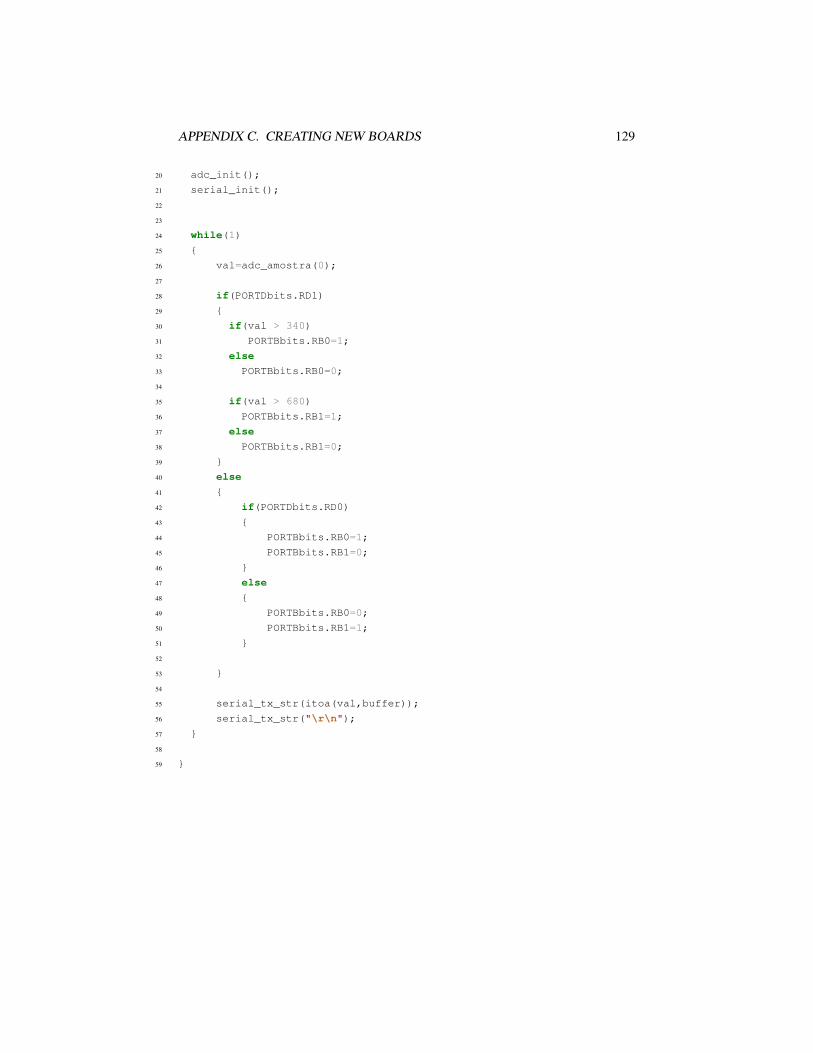
APPENDIX C. CREATING NEW BOARDS 129
20 adc_init();
21 serial_init();
22
23
24 while(1)
25 {
26 val=adc_amostra(0);
27
28 if(PORTDbits.RD1)
29 {
30 if(val > 340)
31 PORTBbits.RB0=1;
32 else
33 PORTBbits.RB0=0;
34
35 if(val > 680)
36 PORTBbits.RB1=1;
37 else
38 PORTBbits.RB1=0;
39 }
40 else
41 {
42 if(PORTDbits.RD0)
43 {
44 PORTBbits.RB0=1;
45 PORTBbits.RB1=0;
46 }
47 else
48 {
49 PORTBbits.RB0=0;
50 PORTBbits.RB1=1;
51 }
52
53 }
54
55 serial_tx_str(itoa(val,buffer));
56 serial_tx_str("\r\n");
57 }
58
59 }