picolay tutorial · picolay tutorial heribert cypionka 2010-09-01 installation in order to install...
TRANSCRIPT

PICOLAY Tutorial Heribert Cypionka 2010-09-01
Installation
In order to install PICOLAY on your computer you only have to download a small file (<1 MB), picolay.exe, and save it in any directory (or even on a USB stick). Don't forget to place a link to the file on your desktop in order to start it easily. That's all installation you need. There is NO CHANGE of any system file on your computer. Note: Even if you are not online and did forget to print out this tutorial, the MANUAL (without images) is available within the program under 'Help'.
Select files (the example stack used here can be downloaded from www.picolay.de/examples)
At first you have to select a set of image files. Click on 'File' and then 'Select pictures' to open a new window. Click on the first image file you want to select, then press the shift-key and hold it pressed, click on the last file of your selection (the selected File names turn blue) and then click on 'Open'. Alternatively, one can keep the Ctrl-key pressed and click on each image separately.

PICOLAY Tutorial Heribert Cypionka - 2 -
A list of the selected file names is shown in the listbox, and the first image is displayed. To display another image just click on its name in the listbox. You can zoom in and out ([+] and [-] on the image window), and you will have the same position with all images. To unmark or mark images, double-click a name, the 'X' in at the left will disappear (or re-appear, if you double-click again). Only marked images will be regarded during stack operations.
Note: All pictures should have the same dimensions (width and height) and have the JPEG, Bitmap or GIF format. Tiff files might work also, but this is not guaranteed. The names of the files should have the same alphabetical sequence as the layers they were taken. You can reverse the order under 'Image list' depending on whether you started with the uppermost or lowermost layer. PICOLAY assumes that the first images shows the uppermost layer and requires the image names in the corresponding alphabetical order. PICOLAY will not change the original files. However, automatically generated files will overwrite older versions. Next time you start PICOLAY the last image directory will be remembered.
Browsing the image list
Hints: - [X] at the left indicates that an image is marked = selected for further operations - Unmarked images [_] will not be included in stacking averaging etc. - Clicking on the name causes display of an image - Double-clicking toggles the mark - The names are sorted by alphabetical order: 1. File = top layer. To reverse the order, click on 'Image list' | 'Reverse list top-down' - F12 starts a slide show af all marked images (see below)
PICOLAY Tutorial Heribert Cypionka - 3 -
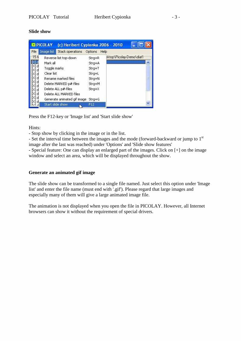
Slide show
Press the F12-key or 'Image list' and 'Start slide show' Hints: - Stop show by clicking in the image or in the list. - Set the interval time between the images and the mode (forward-backward or jump to 1st image after the last was reached) under 'Options' and 'Slide show features' - Special feature: One can display an enlarged part of the images. Click on [+] on the image window and select an area, which will be displayed throughout the show. Generate an animated gif image The slide show can be transformed to a single file named. Just select this option under 'Image list' and enter the file name (must end with '.gif'). Please regard that large images and especially many of them will give a large animated image file. The animation is not displayed when you open the file in PICOLAY. However, all Internet browsers can show it without the requirement of special drivers.

PICOLAY Tutorial Heribert Cypionka - 4 -
Crop images In many cases the images of your stack are larger than the area of interest. To crop the relevant area select a rectangle with your mouse ([Mouse function =] Rectangle). With [Edit] and 'Crop all marked images' clipped images will be generated. The new file names are 'clip#’ + original file name. Hint: Do no cut too small: Stacking requires some edge that can be cut away later.
PICOLAY Tutorial Heribert Cypionka - 5 -
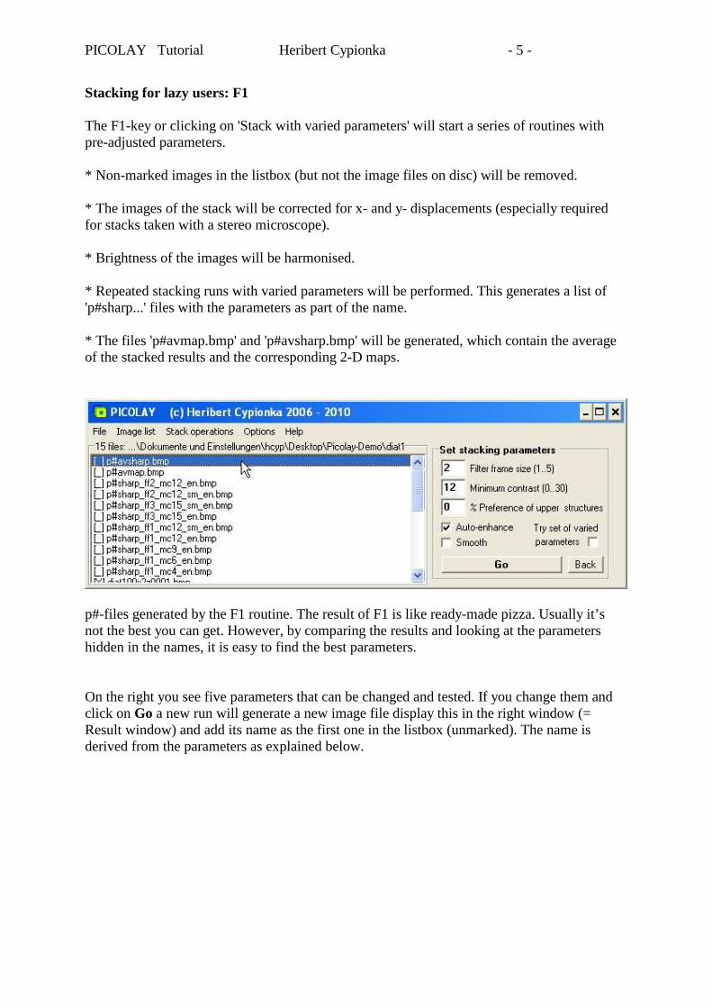
Stacking for lazy users: F1 The F1-key or clicking on 'Stack with varied parameters' will start a series of routines with pre-adjusted parameters. * Non-marked images in the listbox (but not the image files on disc) will be removed. * The images of the stack will be corrected for x- and y- displacements (especially required for stacks taken with a stereo microscope). * Brightness of the images will be harmonised. * Repeated stacking runs with varied parameters will be performed. This generates a list of 'p#sharp...' files with the parameters as part of the name. * The files 'p#avmap.bmp' and 'p#avsharp.bmp' will be generated, which contain the average of the stacked results and the corresponding 2-D maps.
p#-files generated by the F1 routine. The result of F1 is like ready-made pizza. Usually it’s not the best you can get. However, by comparing the results and looking at the parameters hidden in the names, it is easy to find the best parameters. On the right you see five parameters that can be changed and tested. If you change them and click on Go a new run will generate a new image file display this in the right window (= Result window) and add its name as the first one in the listbox (unmarked). The name is derived from the parameters as explained below.

PICOLAY Tutorial Heribert Cypionka - 6 -
How the parameters are encoded in the filenames EXAMPLE File name The file name p#sharp_ff2_mc12_sm_en.jpg tells you that this image was generated by PICOLAY by the sharpness-based stacking routine with a filter frame size of 2, a minimum contrast value set to 12, and with the 2-D map smoothed, and the the final result automatically enhanced . ff = filter frame size defines the radius that is used to measure sharpness. Fine structures require small values (1 to 2), large structures are better detected by large filter squares (3 to 4). mc = minimum contrast: Pixels with a contrast (= sharpness) below the value set here, will be averaged, thus giving a smooth background. However, if the value is set too high, interesting structures will lose sharpness. pr = preference of upper layers. Prevents contrast-rich pixels from being overwritten by those coming from lower layers. This function will be required only, if you have multi-layered objects. sm = Smooth 2-D map. Does not smooth the resulting image but causes usages of larger patches from each layer, thus giving a less noisy result. en = auto-enhance result. This will increase sharpness and contrast (see below). If this function causes strange results check the values set in the enhance panel (reachable from the image window, see below). Do not use this function if you are planning to do manual stacking (clone original pixels to the result) later on.

PICOLAY Tutorial Heribert Cypionka - 7 -
Optimising stacking parameters (1) To find the perfect parameters, it is very helpful to look at the 2-D depth map. This is displayed after clicking on [Flip view=] in the Results window (and switched back after a second click). The map shows a yellow-green-blue Image with yellow for top and blue for bottom layers. Contrast-poor areas are shown in grey. Sharp result and map generated by the F1-routine (ready made…). This is an average of the results obtained with the different parameters.
With a Filter frame size of 1 and a Minumum contrast of 0 the background is noisy. This is due to the fact that there was no minimum contrast required (mc=0). Now we increase this value to mc=15 and start the stacking routine by clicking on 'Go'.
PICOLAY Tutorial Heribert Cypionka - 8 -
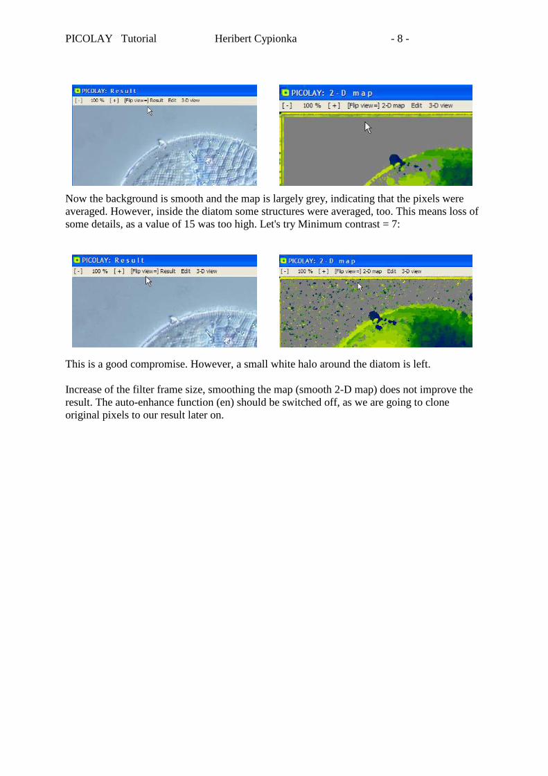
Now the background is smooth and the map is largely grey, indicating that the pixels were averaged. However, inside the diatom some structures were averaged, too. This means loss of some details, as a value of 15 was too high. Let's try Minimum contrast = 7: This is a good compromise. However, a small white halo around the diatom is left. Increase of the filter frame size, smoothing the map (smooth 2-D map) does not improve the result. The auto-enhance function (en) should be switched off, as we are going to clone original pixels to our result later on.
PICOLAY Tutorial Heribert Cypionka - 9 -
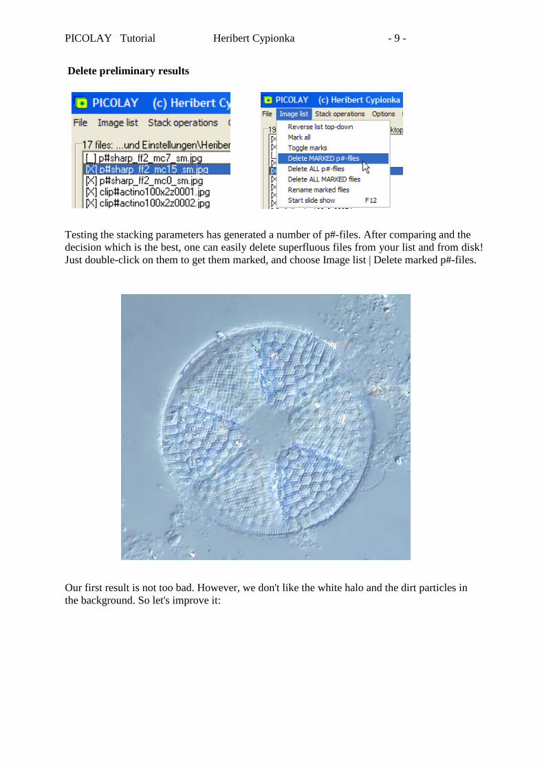
Delete preliminary results Testing the stacking parameters has generated a number of p#-files. After comparing and the decision which is the best, one can easily delete superfluous files from your list and from disk! Just double-click on them to get them marked, and choose Image list | Delete marked p#-files. Our first result is not too bad. However, we don't like the white halo and the dirt particles in the background. So let's improve it:
PICOLAY Tutorial Heribert Cypionka - 10 -
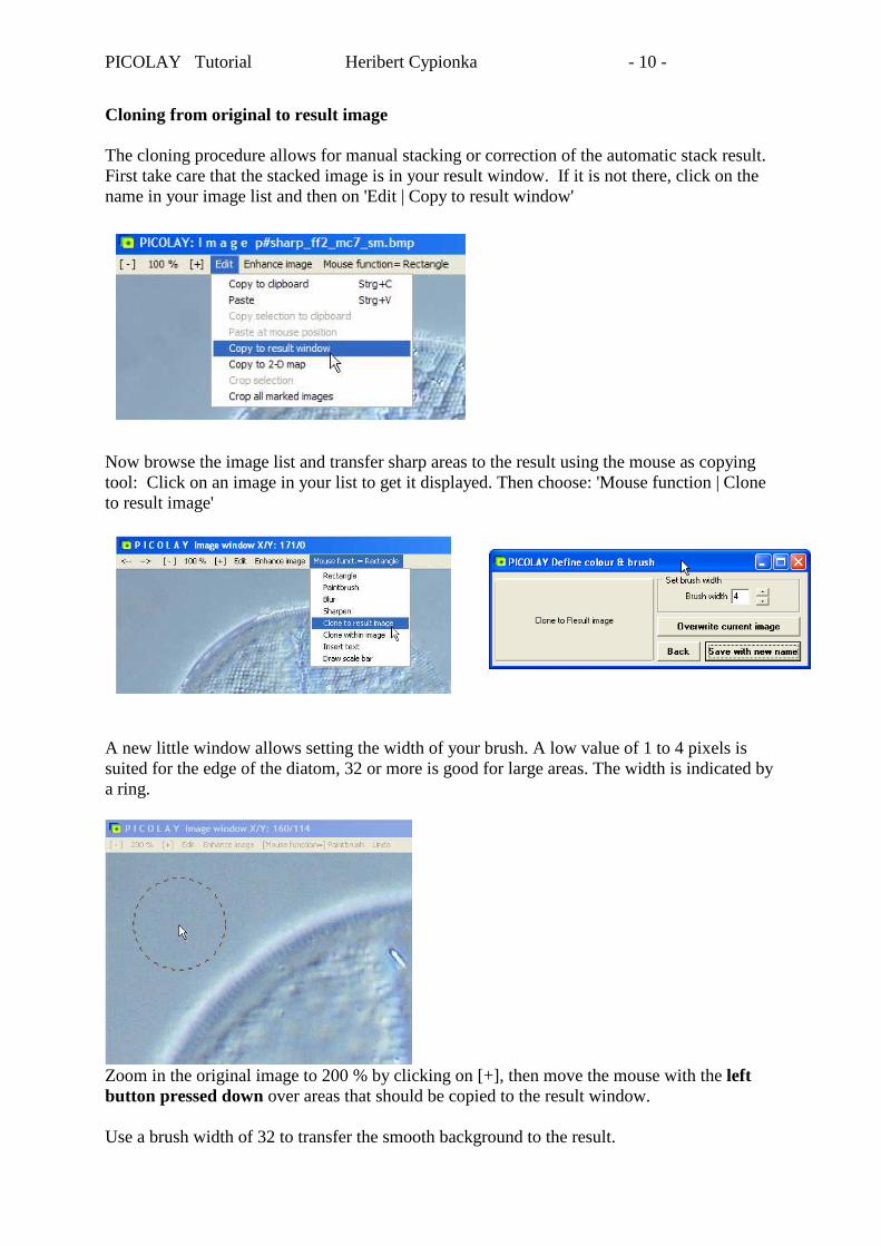
Cloning from original to result image The cloning procedure allows for manual stacking or correction of the automatic stack result. First take care that the stacked image is in your result window. If it is not there, click on the name in your image list and then on 'Edit | Copy to result window' Now browse the image list and transfer sharp areas to the result using the mouse as copying tool: Click on an image in your list to get it displayed. Then choose: 'Mouse function | Clone to result image' A new little window allows setting the width of your brush. A low value of 1 to 4 pixels is suited for the edge of the diatom, 32 or more is good for large areas. The width is indicated by a ring.
Zoom in the original image to 200 % by clicking on [+], then move the mouse with the left button pressed down over areas that should be copied to the result window. Use a brush width of 32 to transfer the smooth background to the result.
PICOLAY Tutorial Heribert Cypionka - 11 -
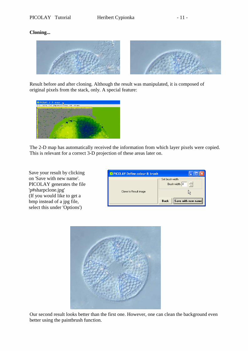
Cloning... Result before and after cloning. Although the result was manipulated, it is composed of original pixels from the stack, only. A special feature: The 2-D map has automatically received the information from which layer pixels were copied. This is relevant for a correct 3-D projection of these areas later on. Our second result looks better than the first one. However, one can clean the background even better using the paintbrush function.
Save your result by clicking on 'Save with new name'. PICOLAY generates the file 'p#sharpclone.jpg' (If you would like to get a bmp instead of a jpg file, select this under 'Options')

PICOLAY Tutorial Heribert Cypionka - 12 -
Manual cleaning with the paintbrush function Click on an image to display it on your screen, then 'Mouse function | Paintbrush' A new window shows up, which allows to set width and colour of the brush. The colour can easily be extracted from your image by clicking on it with the RIGHT mouse button. Here I demonstrate different widths and the increasing transparency from the middle in black. The faster the mouse is moved (now with the left button pressed) the higher is the transparency.
The 'Undo' function allows restoring the image to the state it had when you last time pressed the left mouse button. Pressing 'Ctrl-Z' will do the same. Tip: Instead of pressing the left mouse button one can also keep the control-key pressed, which might be more comfortable for your hand. The result now looks very good. One can save either as new file 'Save with new name' (it will automatically get the filename p#enhanced-02.jpg) or overwrite the it by pressing 'Overwrite current image'. Can you still improve this? A little bit more sharpness and contrast would be desirable...

PICOLAY Tutorial Heribert Cypionka - 13 -
Image enhancement
Open image by clicking in the list, then 'Enhance Image' A new window with the adjustable parameters opens. Change some of the values, and click on the test button to see the consequences, until you have the perfect result. Then 'Apply' to save it, in our case 'p#enhanced-03.jpg' (or .bmp if selected under options). Here I tried to increase sharpness and contrast without making the result too 'hard'. The gamma value and colour saturation were decreased a bit.
This is now an excellent image – with only one major disadvantage: it is stacked! This means, although it looks somehow plastic, it has been digitally ironed flat. The real 3-D structure is not visible any more. However, PICOLAY had generated a 2-D map keeping the information from which layer each pixel is derived. This will now be used to generate 3-D reconstructions.

PICOLAY Tutorial Heribert Cypionka - 14 -
Three-dimensional projections An image and a corresponding depth map are required for simple generation of 3-D image. These were produced by the stacking procedure. The image was even improved as described above. The depth map was changed by cloning. If it is not already there, copy the improved image to the result window:
Now click on '3-D view' to open a new window: Concomitantly the depth map is shown.
No matter about the partially green and grey areas – that's all background. Just click on 'Go' to get a stereo image for your red-cyan anaglyph goggles:

PICOLAY Tutorial Heribert Cypionka - 15 -
3-D projection based on depth map
Anaglyph images for red-cyan goggles. Left: Length of z-axis 40%, Cyan-red shift=0, Seam around 3-D pixels=6; the right image with z=80%, Cyan-red shift=10 und Seam=0 has more depth, appears to be located farther in the background, and shows fissures. The latter will disappear if you increase the seam value. Here an explanation of the parameters to be adjusted in the '3-D view' window: Length of Z axis (% of image height) x- and y-axes are image width and height, respectively. The value for the length of z-axis is given as percent of the image height. After simple stacking the z-axis is invisible, as one looks parallel to it. For stereoscopic viewing two images are generated which differ slightly in the viewing angle and need a value for the length of the z-axis. An exact value would require knowledge of the image height as well as the distance of the top and bottom focus layers. This distance can be read at the focussing wheel of good microscopes. However, one can get a natural impression by playing with the value and looking whether the object seems to get stretched or squeezed when it rotates. Cyan-red shift The shift between the overlaying red and cyan images is adjustable. Positive values move the object into the foreground while negative move it backwards. With a value of zero the mid layer is placed just on the screen. Seam When you increase the length of the z-axis, the spatial depth increases, causing a problem: The area of the stacked image is not sufficient to form the three-dimensional shape. Therefore fissures show up between patches from different layers. These gaps can be filled with the seam around the patches. Increase the value until the fissures have disappeared. When you do hologram stacking (see below) the seam is drawn around every pixel, which reduces the sharpness of the image and makes it look smoother. Set the value to 0 or 1 if this is not wanted.

PICOLAY Tutorial Heribert Cypionka - 16 -
Images to be generated PICOLAY generates 3-D projections not only of the original images, but also of the 2-D map or an overlay of image and map. The image can be transformed to black&white if needed. And one can add a 3-D grid (5x5x5) for scientific purposes. Viewing angle The viewing angle between our eyes is normally between 2 and 5°. It is larger for near than for remote objects. Pairs of two and combined panel with four images Instead of generating a red-cyan image, PICOLAY can also produce pairs of separate images or a panel with 4 combined images that allow for stereoscopic viewing. One can look at these images without goggles with relaxed eyes using a technique known from the 'magic eye' books that were common in the 1990's.
The combined panel allows for 3-D viewing with both parallel and crossed eyes. You stare on it until you see six images. Now you focus on those in the middle which appear in 3-D, the upper one convex, the lower one concave - or vice versa, depending on whether you are looking with crossed or parallel eyes (don't care about this, when it works!).

PICOLAY Tutorial Heribert Cypionka - 17 -
How to look at 3-D image pairs Generally, parallel viewing is difficult with images that are broader than the distance between our eyes (about 6.5 cm). To prevent unwanted cross-viewing, one can use a sheet of paper as separator between the eyes. For cross-viewing one can use the hands to block parallel viewing as shown below:

PICOLAY Tutorial Heribert Cypionka - 18 -
Hologram stacking Finally we are going to rotate our object freely in space, and to unravel new details that were hidden so far. Normal stacking not only flattens the object, it also destroys information, if there are structures in more than one level. Only the pixels with the highest contrast will be displayed, while those from low-contrast layers will be ignored. (With PICOLAY this can be controlled partially by setting a preference for upper layers, see chapter 'Optimising stacking parameters'). If one tilts the object before drawing one can avoid masking of underlying structures that were hidden during simple top-view projection. If you rotate the object all structures should become visible at a suited angle. I called this type of presentation hologram stacking. One needs a threshold value to keep the object partially transparent and to avoid that all pixels of upper layers are displayed and masking the rest. This threshold can be a minimum contrast or similarity to a target colour. For comparison: If you would like to visualise all occurrences and positions of a certain letter in a book (without opening it) the paper should be transparent and the book should be tilted or rotating. Let's apply hologram stacking to our diatom: Check Hologram stacking, a new panel shows up at the right. Background A background colour is required as parts of the area will stay unused during rotation. You can select the average as background. However, for rotations it's often better to to check 'Colour' and select one. Grey is o.k. in this case. You could also click on the black or white square, or on the bar to enter RGB values. Furthermore, one can click on the bar, then suck up the background colour from an original image by clicking on it with the RIGHT mouse button, and confirm the colour by clicking on OK/Close. 3-D Rotation The projection angles of the three axes are entered as numbers. If stepwise rotation is checked, a series (defined by the number of repeats) of images will be generated. The projection angle is each time changed by the angle defined under 'Step'. You can produce red-cyan images, pairs, or panels with four images, or simply tilted projections, if you uncheck '3-D view'. The presentation is most impressive as slide show that can be frozen as animated gif image as described above. For this go back to the main window, toggle marks (under image list) and press F12. Hologram parameters The values for Minimum contrast and Filter frame size often have to be changed compared to the previous stacking, as pixels are not regarded in their neighbourhood any more. A minimum contrast of 0 generates a brick without transparency (see example below). Colour-based hologram stacking is useful for the detection of stains and not demonstrated here.

PICOLAY Tutorial Heribert Cypionka - 19 -
Hologram images (for red-cyan goggles) Diatom Actinoptychus (Parameters: Length of Z axis=30%, Cyan-red shift=0, Viewing angle 2°, mc=6, ff=2) Left X/Y/Z = 0/0/0, right X/Y/Z = 180/0/0. The object is not only turned around, new details become visible at the bottom. Overlay of map and original images. Left X/Y/Z = 60/20/0, right X/Y/Z = 150/20/0. The layers of the images appear as coloured rings. X/Y/Z = 60/20/0, without minimum X/Y/Z = 90/20/0: at 90° rotation contrast (mc=0) the images look like lines

PICOLAY Tutorial Heribert Cypionka - 20 -
Finishing your session Rename your best images To avoid automatic deletion of PICOLAY results, rename the best files. Mark them by double-clicking in the list and click on: 'Image list | Rename marked files':
PICOLAY offers to remove p# from the names of marked files. However, you can make any replacement of strings. When you exit the program PICOLAY offers to delete 'p#...' files:
If you click on 'No', p#-files in your list will be erased from disk. Other files generated by PICOLAY, with names beginning with clip# (cropped images), xy# (positions corrected), b# (brightness adjusted) or enh# (enhanced) will not be deleted automatically. You could do this manually by marking them and carrying out 'Delete all marked files' under 'Image list':
That's it! Good luck and many great images!