picmg® 3.1 ethernet/fibre channel over picmg...
TRANSCRIPT

PICMG® 3.1 Ethernet/Fibre Channel Over PICMG 3.0
Draft Specification
January 14, 2003 Version D1.0
Do Not Specify or Claim Compliance to this Draft Specification

© Copyright 2002, 2003 PCI Industrial Computer Manufacturers Group
The attention of adopters is directed to the possibility that compliance with or adoption of PICMG® specifications may require use of an invention covered by patent rights. PICMG shall not be responsible for identifying patents for which a license may be required by any PICMG specification, or for conducting legal inquiries into the legal validity or scope of those patents that are brought to its attention. PICMG specifications are prospective and advisory only. Prospective users are responsible for protecting themselves against liability for infringement of patents.
Notice: The information contained in this document is subject to change without notice. The material in this document details a PICMG* specification in accordance with the license and notices set forth on this page. This document does not represent a commitment to implement any portion of this specification in any company’s products.
WHILE THE INFORMATION IN THIS PUBLICATION IS BELIEVED TO BE ACCURATE, PICMG MAKES NO WARRANTY OF ANY KIND, EXPRESS OR IMPLIED, WITH REGARD TO THIS MATERIAL INCLUDING, BUT NOT LIMITED TO ANY WARRANTY OF TITLE OR OWNERSHIP, IMPLIED WARRANTY OF MERCHANTABILITY OR WARRANTY OF FITNESS FOR PARTICULAR PURPOSE OR USE.
In no event shall PICMG be liable for errors contained herein or for indirect, incidental, special, consequential, reliance or cover damages, including loss of profits, revenue, data or use, incurred by any user or any third party. Compliance with this specification does not absolve manufacturers of CompactPCI® Hot Swap equipment, from the requirements of safety and regulatory agencies (UL, CSA, FCC, IEC, etc.).
PICMG, CompactPCI®, and the PICMG logos are registered trademarks of the PCI Industrial Computer Manufacturers Group.
All other brand or product names may be trademarks or registered trademarks of their respective holders.
PICMG 3.1 Draft Specification v1.0 Released on: January 14, 2003 2 Do Not Design To/Do Not Claim Compliance To/Do Not Distribute This Specification

Contents
1 INTRODUCTION AND OBJECTIVES.........................................................................................................................................6 1.1 Objectives..........................................................................................................................................................................6 1.2 Reference documents ......................................................................................................................................................7
1.2.1 Reference specifications ...................................................................................................................................7 1.2.2 Environment and regulatory documents ...........................................................................................................8
1.3 Contributors ......................................................................................................................................................................8 1.4 Special word usage ..........................................................................................................................................................8 1.5 Name and logo usage.......................................................................................................................................................8 1.6 Signal naming conventions .............................................................................................................................................9 1.7 Intellectual property .........................................................................................................................................................9 1.8 Acronyms and definitions................................................................................................................................................9
2 PICMG 3.0 COMPLIANCE ........................................................................................................................................................10 2.1 Mechanical ......................................................................................................................................................................10 2.2 Power distribution ..........................................................................................................................................................10 2.3 Thermal............................................................................................................................................................................10
3 SYSTEM MANAGEMENT .........................................................................................................................................................11 3.1 Introduction.....................................................................................................................................................................11 3.2 PICMG 3.1 implementation requirements.....................................................................................................................11
3.2.1 Implementation independent requirements.....................................................................................................11 3.3 Messaging algorithm......................................................................................................................................................11 3.4 E-Ke ing extensions ......................................................................................................................................................11 y
3.4.1 Link Descriptor ................................................................................................................................................12 3.4.2 LDES: Link Designator....................................................................................................................................12 3.4.3 LTYPE: Link Type ...........................................................................................................................................12 3.4.4 LEXT: Link Type Extension.............................................................................................................................12
3.5 Link and Link Descriptor Options.................................................................................................................................13 3.6 Fabric Interface ...............................................................................................................................................................17
4 DATA TRANSPORT..................................................................................................................................................................18 4.1 Introduction.....................................................................................................................................................................18 4.2 Pin assignments .............................................................................................................................................................19
5 BACKPLANE PHYSICAL LAYER INTERFACES ....................................................................................................................21 5.1 Giga it backplane interface, 1000BASE-BX/FC-PI ......................................................................................................21 b
5.1.1 1000BASE-BX/FC-PI transmitter electrical specifications ..............................................................................22 5.1.2 1000BASE-BX/FC-PI receiver electrical specifications...................................................................................24 5.1.3 1000BASE-BX/FC-PI jitter specifications........................................................................................................26
5.2 10 G t backplane interface, 10GBASE-BX4...........................................................................................................27 igabi5.2.1 10GBASE-BX4 transmitter electrical specifications........................................................................................27 5.2.2 10GBASE-BX4 receiver electrical specifications ............................................................................................29 5.2.3 10GBASE-BX4 TP-T and TP-R eye mask ......................................................................................................30
5.3 Gigabit to 10 gigabit auto negotiation (AN)..................................................................................................................31
PICMG 3.1 Draft Specification v1.0 Released on: January 14, 2003 3 Do Not Design To/Do Not Claim Compliance To/Do Not Distribute This Specification
Figures Figure 1 - SerDes Ethernet/Fibre Channel electrical environment.................................................................................................21 Figure 2 – 1000BASE-BX/FC-PI testpoints .......................................................................................................................................22 Figure 3 - Transmit testpoint TP-T ....................................................................................................................................................23 Figure 4 - Absolute eye diagram mask at TP-T ................................................................................................................................24 Figure 5 - Receive testpoint TP-R......................................................................................................................................................24 Figure 6 - Received eye mask at TP-R ..............................................................................................................................................26 Figure 7 - 10GBASE-BX4 electrical environment.............................................................................................................................27 Figure 8-Compliance interconnect magnitude response and ISI loss...........................................................................................29 Figure 9 - TP-T and TP-R eye mask...................................................................................................................................................30
Tables Table 1 - PICMG 3.1 Link Extension – (LEXT – 4bit field)................................................................................................................13 Table 2 - Link Options ........................................................................................................................................................................13 Table 3 – Example Link Descriptor, One 1000BASE-BX .................................................................................................................14 Table 4 - – Example Link Descriptor, Two 1000BASE-BX...............................................................................................................14 Table 5 - – Example Link Descriptor, Four 1000BASE-BX..............................................................................................................14 Table 6 - – Example Link Descriptor, One 1000BASE-BX, One FC ................................................................................................15 Table 7 - – Example Link Descriptor, Two 1000BASE-BX, One FC ................................................................................................15 Table 8 - – Example Link Descriptor, Two 1000BASE-BX, Two FC................................................................................................16 Table 9 - – Example Link Descriptor, One FC ..................................................................................................................................16 Table 10 - – Example Link Descriptor, Two FC ................................................................................................................................17 Table 11 - – Example Link Descriptor, One 10BASE-BX4 ...............................................................................................................17 Table 12 - AdvancedTCA™ Fabric Interface generic pin mappings ..............................................................................................18 Table 13 - PICMG 3.1 Channel options .............................................................................................................................................19 Table 14 - Channel Interface pin Assignments for 1000BASE-BX Ethernet Ports .......................................................................19 Table 15 - 1000BASE-BX Ethernet with Fibre Channel pin assignments ......................................................................................20 Table 16 - Channel Interface pin mappings for 10GBASE-BX4 (10 Gbps XAUI)...........................................................................20 Table 17 - Transmitter specifications at TP-T ..................................................................................................................................23 Table 18 - Transmitter specifications at TP-T ..................................................................................................................................24 Table 19 - Receiver specifications at TP-R.......................................................................................................................................25 Table 20 - Jitter Budget ......................................................................................................................................................................26 Table 21 - Transmit specifications at TP-T .......................................................................................................................................28 Table 22 - Receiver specifications at TP-R.......................................................................................................................................30
PICMG 3.1 Draft Specification v1.0 Released on: January 14, 2003 4 Do Not Design To/Do Not Claim Compliance To/Do Not Distribute This Specification
Revision History
Date Revision Changes
14-Jan-03 1.0 Original Release
PICMG 3.1 Draft Specification v1.0 Released on: January 14, 2003 5 Do Not Design To/Do Not Claim Compliance To/Do Not Distribute This Specification
1 Introduction and objectives
The PICMG® 3.1 specification is a member of the PICMG 3 AdvancedTCA™ series of specifications. The base specification in the family, PICMG 3.0, is required to understand this specification. The PICMG 3.0 base specification implements a plug-in card & chassis architecture where the plug-in cards all have point-to-point differential pair serial-data links to communicate with each other. The base design is sufficiently generic that it can accommodate many different link-level standards. PICMG 3.1 establishes the usage of Ethernet (IEEE 802.3) and Fibre Channel (NCITS T11) communication within the AdvancedTCA™ chassis.
Ethernet is a highly successful LAN (Local Area Network) standard with support from a wide array of silicon, board, and software vendors. Originally developed by a consortium consisting of Digital Equipment Corporation, Intel, and Xerox (“DIX”) it was eventually standardized in 1983. Higher speeds of operation and other new capabilities have been defined and incorporated into the standard over the years. IEEE 802.3 and its amendments are approved as national standards by ANSI, and international standards by ISO, although these approvals will lag from IEEE Standards Association approval. The international standards are published as ISO/IEC 8802-3. The Ethernet standards referred to by PICMG 3.1 are listed in Section 1.2.1 on page 7.
Fibre Channel has become a very popular standard for the connection of disk media storage systems with processors to form SANs (Storage Area Networks). It has been incorporated into PICMG 3.1 to allow the development of chassis units with mass storage in addition to processing and switching. PICMG 3.1 supports a Fibre Channel Port as FC-PI. The default for a FC-PI Port is 1 Gig/s, however if both ends have autonegotiation implemented, a datarate of 2 Gig/s can be achieved. In general, the use of Fibre Channel is expected to be used in parallel with Ethernet, although PICMG 3.1 does not preclude the use of Fibre Channel only.
It is expected that 10 Gigabit Ethernet, when fully developed, will include the capability of integrating both the SAN and the LAN function. PICMG 3.1 supports 10 Gigabit Ethernet via AdvancedTCA™ channels using XAUI signaling.
A similar architecture to PICMG 3.1 (for Ethernet only) was developed by the PICMG 2.16 sub-committee, whose Revision 1.0 standard was published on September 5, 2001. Many of the members of the PICMG 2.16 sub-committee are now participating in the PICMG 3.1 sub-committee.
1.1 Objectives The specification in this document is wholly derived from and is dependent upon, the PICMG 3.0 base specification. It is not intended to stand-alone or to be used separately from the base specification.
PICMG 3.1 builds upon the PICMG 3.0 base specification, the IEEE 802.3-2003 specifications as well as the Fibre Channel FC-PI specifications, to meet the following objectives:
• Define the signals to be used over the data link channels provided by PICMG 3.0 based on Ethernet/Fibre Channel-compatible devices.
• Support over each PICMG 3.0 Channel the option of
o One Port of SerDes Gigabit Ethernet/Fibre Channel
o Two Ports (Link-aggregated optional) of SerDes Gigabit Ethernet/Fibre Channel
PICMG 3.1 Draft Specification v1.0 Released on: January 14, 2003 6 Do Not Design To/Do Not Claim Compliance To/Do Not Distribute This Specification
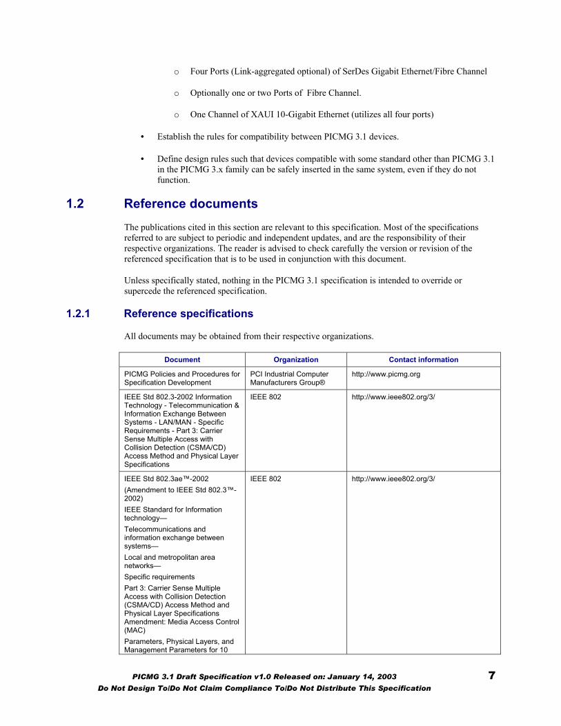
o Four Ports (Link-aggregated optional) of SerDes Gigabit Ethernet/Fibre Channel
o Optionally one or two Ports of Fibre Channel.
o One Channel of XAUI 10-Gigabit Ethernet (utilizes all four ports)
• Establish the rules for compatibility between PICMG 3.1 devices.
• Define design rules such that devices compatible with some standard other than PICMG 3.1 in the PICMG 3.x family can be safely inserted in the same system, even if they do not function.
1.2 Reference documents The publications cited in this section are relevant to this specification. Most of the specifications referred to are subject to periodic and independent updates, and are the responsibility of their respective organizations. The reader is advised to check carefully the version or revision of the referenced specification that is to be used in conjunction with this document.
Unless specifically stated, nothing in the PICMG 3.1 specification is intended to override or supercede the referenced specification.
1.2.1 Reference specifications
All documents may be obtained from their respective organizations.
Document Organization Contact information
PICMG Policies and Procedures for Specification Development
PCI Industrial Computer Manufacturers Group®
http://www.picmg.org
IEEE Std 802.3-2002 Information Technology - Telecommunication & Information Exchange Between Systems - LAN/MAN - Specific Requirements - Part 3: Carrier Sense Multiple Access with Collision Detection (CSMA/CD) Access Method and Physical Layer Specifications
IEEE 802 http://www.ieee802.org/3/
IEEE Std 802.3ae™-2002 (Amendment to IEEE Std 802.3™-2002) IEEE Standard for Information technology— Telecommunications and information exchange between systems— Local and metropolitan area networks— Specific requirements Part 3: Carrier Sense Multiple Access with Collision Detection (CSMA/CD) Access Method and Physical Layer Specifications Amendment: Media Access Control (MAC) Parameters, Physical Layers, and Management Parameters for 10
IEEE 802 http://www.ieee802.org/3/
PICMG 3.1 Draft Specification v1.0 Released on: January 14, 2003 7 Do Not Design To/Do Not Claim Compliance To/Do Not Distribute This Specification

Document Organization Contact information Gb/s Operation
PICMG 3.0 Draft Specification PCI Industrial Computer Manufacturers Group®
http://www.picmg.org
INCITS-352 Fibre Channel Physical Interfaces (FC-PI) Information technology - Fibre Channel 1998 Physical Interface (FC-PI'98)
INCITS T11 http://www.t11.org
1.2.2 Environment and regulatory documents
All environment and regulatory requirements that pertain to the PICMG 3.1 specification are cited within the PICMG 3.0 base specification.
1.3 Contributors The following companies participated in the PICMG 3.1 Final Subcommitte ballot:.
Advanet Inc. APW Electronic Solutions Brooktrout Technology
Crystal Group Inc. Communication Automation Force Computers
General Micro systems GNP Computers Hewlett Packard
Hybricon Intel Corporation Interphase Corporation
Lucent Technologies Motorola Computer Group Pentair/Schroff
Performance Technologies, Inc. Pigeon Point Systems RadiSys Corporation
Ramix Rittal/Kaparel Corporation SBS Communications Products
Tyco Electronics VMIC Xilinx
ZNYX Networks
1.4 Special word usage In this specification the following key words (in bold text) will be used:
may: Indicates flexibility of choice with no implied preference.
should: Indicates flexibility of choice with a strongly preferred implementation. The use of should not (in bold text) indicates a flexibility of choice with a strong preference that the choice or implementation should be prohibited.
shall: Indicates a mandatory requirement. Designers shall implement such mandatory requirements to ensure interchangeability and to claim conformance with this specification. The use of shall not (in bold text) indicates an action or implementation that is prohibited.
Note: When not in bold text, the words “may,” “should,” and “shall” are being used in the traditional sense; that is, they do not adhere to the strict meanings described above.
1.5 Name and logo usage The PCI Industrial Computer Manufacturers Group’s policy regarding the use of the registered trademarks PICMG, AdvancedTCA™, and the PICMG, AdvancedTCA™ logos is as follows:
PICMG 3.1 Draft Specification v1.0 Released on: January 14, 2003 8 Do Not Design To/Do Not Claim Compliance To/Do Not Distribute This Specification
Any company may claim compatibility with PICMG, whether a member of the PICMG or not.
Permission to use the PICMG ® and AdvancedTCA™ logo is automatically granted to designated members only as stipulated on the most recent Membership Privileges document during the period of time for which their membership dues are paid.
Member’s distributors and sales representatives may use the PICMG and AdvancedTCA™ logo in promoting member’s products sold under the name of the member.
The PICMG and AdvancedTCA™ logos shall be printed in black or in color as illustrated on the Logo Page that is available from the PICMG at the address above. The center bar of the logo containing the phrase “PICMG” or “AdvancedTCA™” is set horizontally and the aspect ratio of the logo shall be maintained, but the size may be varied. Nothing may be added to or deleted from the PICMG and AdvancedTCA™ logos.
Since the PICMG and AdvancedTCA™ logos, and the PICMG and AdvancedTCA™ names are registered trademarks of the PICMG, the following statement shall be included in all published literature and advertising material in which the logo appears: PICMG, AdvancedTCA™ and the PICMG, AdvancedTCA™ logos are registered trademarks of the PCI Industrial Computer Manufacturers Group.
1.6 Signal naming conventions All signals are active high unless denoted by a trailing # symbol. Differential signals are denoted by a trailing + (positive) or – (negative) symbol.
1.7 Intellectual property The PICMG 3.1 Specification conforms to the Intellectual Property guidelines outlined in the PICMG Policies and Procedures for Specification Development.
1.8 Acronyms and definitions The following terms and acronyms are used in specific ways throughout this document. The PICMG 3.0 base specification also provides an extensive glossary of terms that are used in this document.
CAT5 CATegory 5
FC-PI Fibre Channel-Physical Interface
ISO International Standards Organization
XAUI 10 Gigabit Attachment Unit Interface
PICMG 3.1 Draft Specification v1.0 Released on: January 14, 2003 9 Do Not Design To/Do Not Claim Compliance To/Do Not Distribute This Specification
2 PICMG 3.0 compliance
The PICMG 3.1 specification is wholly derived from the PICMG 3.0 specification, which fully addresses all issues regarding mechanical form, power distribution, and thermal characteristics. The notes provided in this section are provided for continuity; no exceptions to the base specification have been taken.
2.1 Mechanical A PICMG 3.1 board shall conform to all the mechanical specifications set forth in PICMG 3.0 as detailed by Section 2 and other sections of the PICMG 3.0 specification.
2.2 Power distribution A PICMG 3.1 board shall conform to all the power specifications set forth in PICMG 3.0 as detailed by Section 4 and other sections of the PICMG 3.0 specification.
2.3 Thermal A PICMG 3.1 board shall conform to all the thermal specifications set forth in PICMG 3.0 as detailed by Section 5 and other sections of the PICMG 3.0 specification.
PICMG 3.1 Draft Specification v1.0 Released on: January 14, 2003 10 Do Not Design To/Do Not Claim Compliance To/Do Not Distribute This Specification
3 System management
3.1 Introduction The PICMG 3.1 System Manageability requirements are derived from and based upon the features provisioned in Section 3, Shelf Management, of the PICMG 3.0 base specification. System Manageability is applicable to Ethernet/Fibre Channel over the Fabric interface.
Two states where system manageability is most evident in its interaction with the Ethernet/Fibre Channel signaling are:
• At System Power on
• During Insertion or Extraction of a Hub or Node Board.
The architecture of the control interface between system management and the Ethernet/Fibre Channel implementation is based on event messaging. Event messaging is used to facilitate both Electronic-Keying (E-Keying) and power state protocol processes. Ultimately, the actions taken by the Node and Hub Boards, in order to comply with the E-Keying and power management messages, are implementation dependent. Please refer to Section 3 of PICMG 3.0 for further details on E-Keying and power management.
3.2 PICMG 3.1 implementation requirements
3.2.1 Implementation independent requirements
PICMG 3.1 compliant connections shall support E-Keying between the Shelf Manager and the IPM Controller.
PICMG 3.1 compliant designs shall adhere to the requirements of the PICMG 3.0 base specification, Section 3. The most noteworthy requirements pertain to E-Keying, power management, and the existence of an IPM Controller on the node and Hub boards. Further, compliant designs shall have the capability to respond to the Set Port State (Disable) command.
3.3 Messaging algorithm Upon detection of a Hub or Node Board during the power-on state or Board insertion, the Link Designator, Link Type, Link Extension, and Link Grouping are read by the the Shelf Manager from FRU information. The Shelf Manager determines if the Port partners are compatible, returning a message via the IPMB-0 management bus to the IPM Controller on the respective Hub or Node Board. The Shelf Manager determination of matching ports is based on a comparison of each of the Link Descriptor fields. Upon identifying a match, an event message is returned to the IPM Controller, stating that the Link should be enabled or disabled augmented with a description of the Channel capabilities required. This process is detailed in Section 3, of the PICMG 3.0 base specification.
3.4 E-Keying extensions The Link Type and Link Designator (Ports and Channels) are defined within the PICMG 3.0 shelf management section. One of the main underlying assumptions of E-Keying is that a capabilities description (a.k.a. Link description contained in the FRU) is read by the Shelf Manager for every Port present in the Channel. The Link Descriptors are sent in order of preference. The Shelf Manager
PICMG 3.1 Draft Specification v1.0 Released on: January 14, 2003 11 Do Not Design To/Do Not Claim Compliance To/Do Not Distribute This Specification
proceeds with its comparison of the Port partner’s capabilities, all being received by the Shelf Manager in order of preference. The actual Links enabled are determined by application dependent policies implemented in the Shelf Manager.
3.4.1 Link Descriptor
Each Node and Hub board must provide information about each link to the Shelf Manager upon insertion and initialization. For the Board FRU information, the capabilities of all Fabric Channels and Ports are recorded via the Link Descriptor, which has four fields:
Link Designator, comprised of Channel Number (6bits) Interface (2bits) 00b = Base Interface 01b = Fabric Interface 10b = Update Channel Interface 11b = Reserved Port 0-3 Flags (4 bits)
Link Type (8 bits) 00h = Reserved 01h = PICMG 3.0 Base Interface 10/100/1000 BASE-T 02h = PICMG 3.1 Ethernet Fabric Interface 03h = PICMG 3.2 Infiniband Fabric Interface 04h = PICMG 3.3 StarFabric Fabric Interface 05h = PICMG 3.4 PCI Express Fabric Interface 06h .. EFh = Reserved F0h .. FEh = OEM FFh = Reserved
Link Extension = (4 bits)
Link Group ID (8 bits)
3.4.2 LDES: Link Designator
The Link Designator uniquely identifies the channel, interface, and port being described. For PICMG 3.1, only 1000BASE-BX, Fibre Channel and 10BASE-BX4 technologies are permitted to be used on the Fabric Interface.
3.4.3 LTYPE: Link Type
The Link Type values are assigned one per subsidiary specification. For PICMG 3.1, the value 0x02h has been assigned.
3.4.4 LEXT: Link Type Extension
The Link Type Extension bits are governed by the subsidiary specification and have no meaning outside of the context of the specification. They are used by system management as a comparison flag, and cannot be assumed to convey information to system management other than match or mismatch.
PICMG 3.1 Draft Specification v1.0 Released on: January 14, 2003 12 Do Not Design To/Do Not Claim Compliance To/Do Not Distribute This Specification

Table 1 - PICMG 3.1 Link Extension – (LEXT – 4bit field)
LEXT value Description
0x00 Fixed 1000BASE-BX
0x01 Fixed 10GBASE-BX4 [XAUI]
0x02 FC-PI
0x03 – 0xAF Reserved by PICMG 3.1
0xB0 – 0xFE OEM
0xFF Reserved
LGID: Link Grouping ID
The Link Group ID flag is used to indicate multiple channels which are operated in concert on a card. All Channels operated as a group on a Board are assigned the same, non-zero value. A LGID value of 00h value always indicates an independent port.
Note that the system management does not compare LGID values between boards, only between the Channels on a single board.
3.5 Link and Link Descriptor Options Nine port configurations are defined in this specification for implementing Ethernet and Fibre Channel within the channel, as called out in Table 2 below. Link configurations not listed in the table are not defined nor supported within the PICMG 3.1 specification.
Table 2 - Link Options
Option Port 0 Port 1 Port 2 Port 3 Descriptions
1 √ One 1000BASE-BX
2 √ √ Two 1000BASE-BX
3 √ √ √ √ Four 1000BASE-BX
√ One 1000BASE-BX 4
√ One FC-PI
√ √ Two 1000BASE-BX 5
√ One FC-PI
√ √ Two 1000BASE-BX 6
√ √ Two FC-PI
7 √ One FC-PI
8 √ √ Two FC-PI
9 √ √ √ √ One 10GBASE-BX4
Table 3 through Table 11, Example Link Descriptors, show the sample Link Descriptor List parameters by Link option.
PICMG 3.1 Draft Specification v1.0 Released on: January 14, 2003 13 Do Not Design To/Do Not Claim Compliance To/Do Not Distribute This Specification
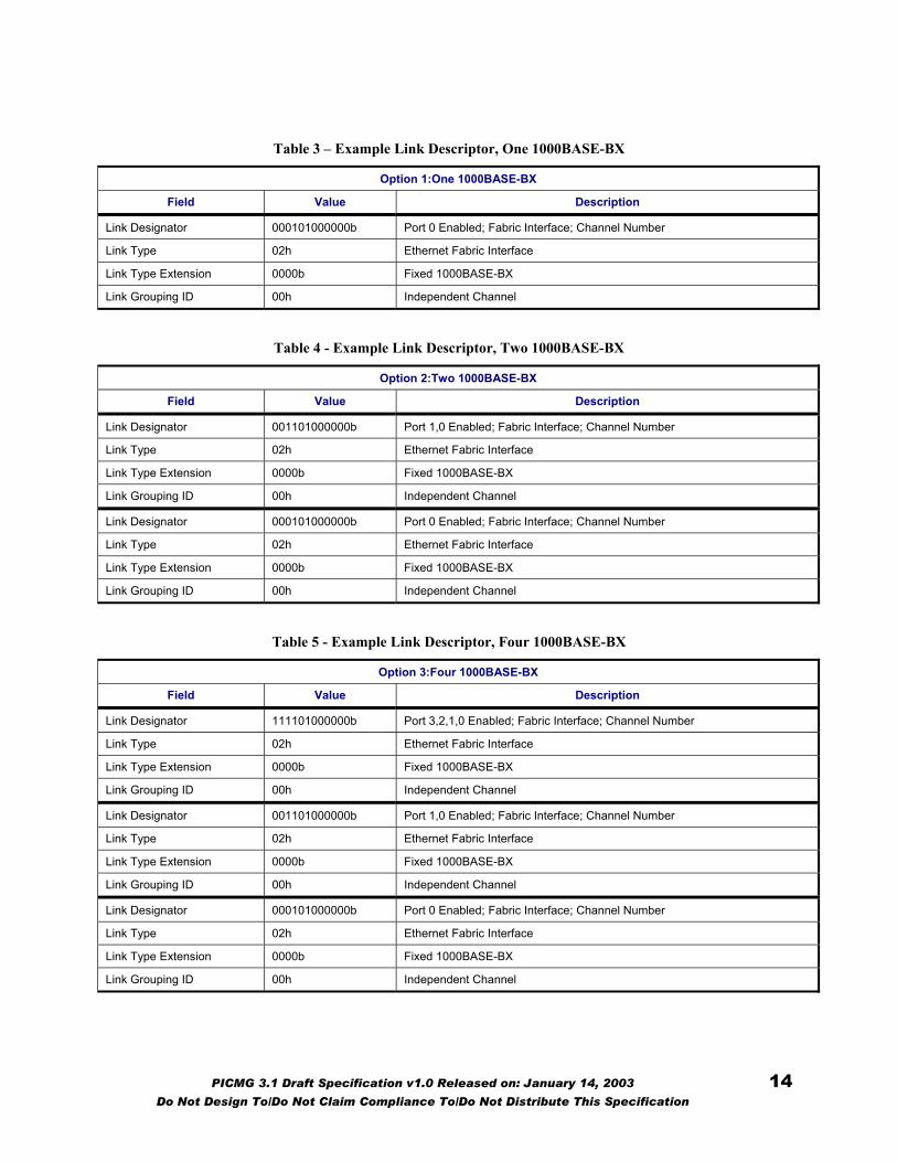
Table 3 – Example Link Descriptor, One 1000BASE-BX
Option 1:One 1000BASE-BX
Field Value Description
Link Designator 000101000000b Port 0 Enabled; Fabric Interface; Channel Number
Link Type 02h Ethernet Fabric Interface
Link Type Extension 0000b Fixed 1000BASE-BX
Link Grouping ID 00h Independent Channel
Table 4 - Example Link Descriptor, Two 1000BASE-BX
Option 2:Two 1000BASE-BX
Field Value Description
Link Designator 001101000000b Port 1,0 Enabled; Fabric Interface; Channel Number
Link Type 02h Ethernet Fabric Interface
Link Type Extension 0000b Fixed 1000BASE-BX
Link Grouping ID 00h Independent Channel
Link Designator 000101000000b Port 0 Enabled; Fabric Interface; Channel Number
Link Type 02h Ethernet Fabric Interface
Link Type Extension 0000b Fixed 1000BASE-BX
Link Grouping ID 00h Independent Channel
Table 5 - Example Link Descriptor, Four 1000BASE-BX
Option 3:Four 1000BASE-BX
Field Value Description
Link Designator 111101000000b Port 3,2,1,0 Enabled; Fabric Interface; Channel Number
Link Type 02h Ethernet Fabric Interface
Link Type Extension 0000b Fixed 1000BASE-BX
Link Grouping ID 00h Independent Channel
Link Designator 001101000000b Port 1,0 Enabled; Fabric Interface; Channel Number
Link Type 02h Ethernet Fabric Interface
Link Type Extension 0000b Fixed 1000BASE-BX
Link Grouping ID 00h Independent Channel
Link Designator 000101000000b Port 0 Enabled; Fabric Interface; Channel Number
Link Type 02h Ethernet Fabric Interface
Link Type Extension 0000b Fixed 1000BASE-BX
Link Grouping ID 00h Independent Channel
PICMG 3.1 Draft Specification v1.0 Released on: January 14, 2003 14 Do Not Design To/Do Not Claim Compliance To/Do Not Distribute This Specification

Table 6 - Example Link Descriptor, One 1000BASE-BX, One FC
Option 4:One 1000BASE-BX, One FC
Field Value Description
Link Designator 000101000000b Port 0 Enabled; Fabric Interface; Channel Number
Link Type 02h Ethernet Fabric Interface
Link Type Extension 0000b Fixed 1000BASE-BX
Link Grouping ID 00h Independent Channel
Link Designator 100001000000b Port 3 Enabled; Fabric Interface; Channel Number
Link Type 02h Ethernet Fabric Interface
Link Type Extension 0010b FC-PI
Link Grouping ID 00h Independent Channel
Table 7 - Example Link Descriptor, Two 1000BASE-BX, One FC
Option 5:Four 1000BASE-BX
Field Value Description
Link Designator 001101000000b Port 1,0 Enabled; Fabric Interface; Channel Number
Link Type 02h Ethernet Fabric Interface
Link Type Extension 0000b Fixed 1000BASE-BX
Link Grouping ID 00h Independent Channel
Link Designator 000101000000b Port 0 Enabled; Fabric Interface; Channel Number
Link Type 02h Ethernet Fabric Interface
Link Type Extension 0000b Fixed 1000BASE-BX
Link Grouping ID 00h Independent Channel
Link Designator 100001000000b Port 3 Enabled; Fabric Interface; Channel Number
Link Type 02h Ethernet Fabric Interface
Link Type Extension 0010b FC-PI
Link Grouping ID 00h Independent Channel
PICMG 3.1 Draft Specification v1.0 Released on: January 14, 2003 15 Do Not Design To/Do Not Claim Compliance To/Do Not Distribute This Specification
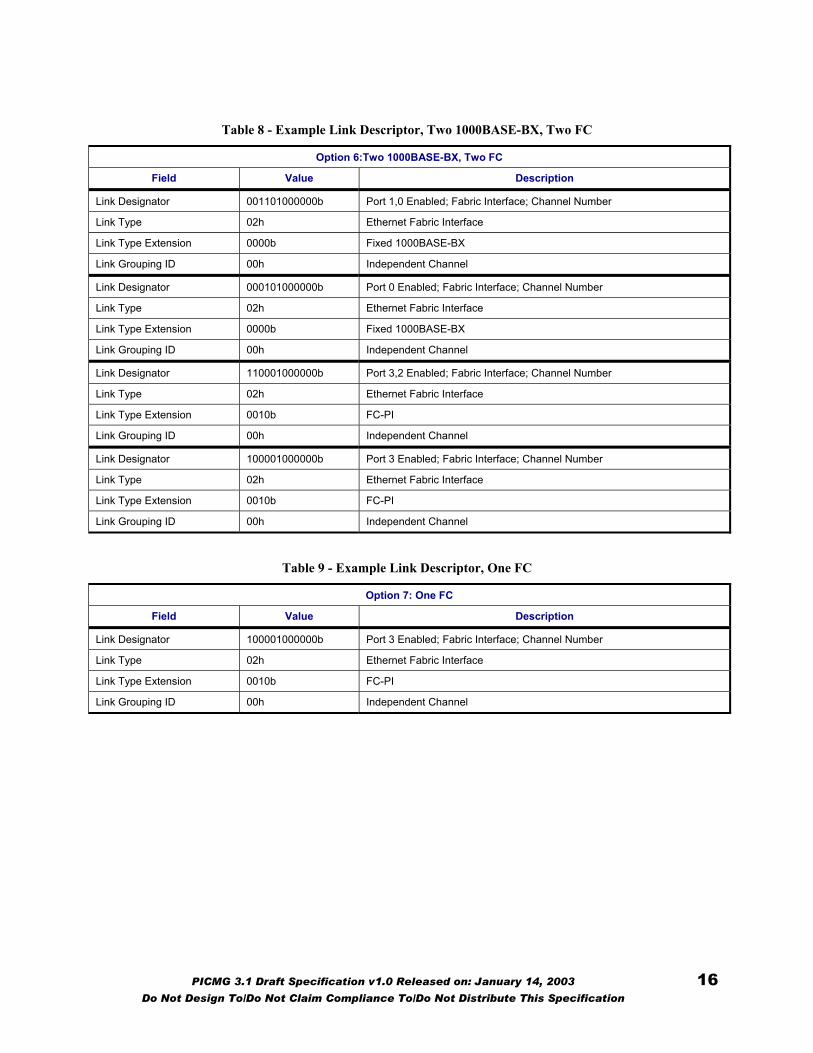
Table 8 - Example Link Descriptor, Two 1000BASE-BX, Two FC
Option 6:Two 1000BASE-BX, Two FC
Field Value Description
Link Designator 001101000000b Port 1,0 Enabled; Fabric Interface; Channel Number
Link Type 02h Ethernet Fabric Interface
Link Type Extension 0000b Fixed 1000BASE-BX
Link Grouping ID 00h Independent Channel
Link Designator 000101000000b Port 0 Enabled; Fabric Interface; Channel Number
Link Type 02h Ethernet Fabric Interface
Link Type Extension 0000b Fixed 1000BASE-BX
Link Grouping ID 00h Independent Channel
Link Designator 110001000000b Port 3,2 Enabled; Fabric Interface; Channel Number
Link Type 02h Ethernet Fabric Interface
Link Type Extension 0010b FC-PI
Link Grouping ID 00h Independent Channel
Link Designator 100001000000b Port 3 Enabled; Fabric Interface; Channel Number
Link Type 02h Ethernet Fabric Interface
Link Type Extension 0010b FC-PI
Link Grouping ID 00h Independent Channel
Table 9 - Example Link Descriptor, One FC
Option 7: One FC
Field Value Description
Link Designator 100001000000b Port 3 Enabled; Fabric Interface; Channel Number
Link Type 02h Ethernet Fabric Interface
Link Type Extension 0010b FC-PI
Link Grouping ID 00h Independent Channel
PICMG 3.1 Draft Specification v1.0 Released on: January 14, 2003 16 Do Not Design To/Do Not Claim Compliance To/Do Not Distribute This Specification
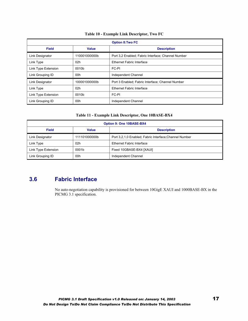
Table 10 - Example Link Descriptor, Two FC
Option 8:Two FC
Field Value Description
Link Designator 110001000000b Port 3,2 Enabled; Fabric Interface; Channel Number
Link Type 02h Ethernet Fabric Interface
Link Type Extension 0010b FC-PI
Link Grouping ID 00h Independent Channel
Link Designator 100001000000b Port 3 Enabled; Fabric Interface; Channel Number
Link Type 02h Ethernet Fabric Interface
Link Type Extension 0010b FC-PI
Link Grouping ID 00h Independent Channel
Table 11 - Example Link Descriptor, One 10BASE-BX4
Option 9: One 10BASE-BX4
Field Value Description
Link Designator 111101000000b Port 3,2,1,0 Enabled; Fabric Interface;Channel Number
Link Type 02h Ethernet Fabric Interface
Link Type Extension 0001b Fixed 10GBASE-BX4 [XAUI]
Link Grouping ID 00h Independent Channel
3.6 Fabric Interface No auto-negotiation capability is provisioned for between 10GigE XAUI and 1000BASE-BX in the PICMG 3.1 specification.
PICMG 3.1 Draft Specification v1.0 Released on: January 14, 2003 17 Do Not Design To/Do Not Claim Compliance To/Do Not Distribute This Specification

4 Data Transport
4.1 Introduction Each AdvancedTCA™ Fabric Interface Channel provides eight differential-signal pairs that are used for board-to-board communication. Up to 15 Fabric Interface Channels are provided, which are distributed according the rules detailed in Section 6 of the PICMG 3.0 specification. Each Fabric Interface Channel uses two rows of the connectors in Zone 2, with generic pin mappings as shown in Table 12.
Note: In PICMG 3.0 terminology, each two-pairs (one pair of transmit and one pair of receive) is referred to as a “port.” The pins with “0” in the name are part of Port 0, “1” in the name indicates Port 1, etc.
Table 12 - AdvancedTCA™ Fabric Interface generic pin mappings
ZD Pin / Row #
A B C D E F G H
n Tx2+ Tx2- Rx2+ Rx2- Tx3+ Tx3- Rx3+ Rx3- Fabric Channel
n + 1 Tx0+ Tx0- Rx0+ Rx0- Tx1+ Tx1- Rx1+ Rx1-
In addition, PICMG 3.0 Section 8 specifies the electrical characteristics of the channels, which make them usable as a medium for the two backplane Fabric link implementations defined by PICMG 3.1:
• 1000BASE-BX Ethernet or FC-PI: one Tx pair and one Rx pair to carry 1 Gigabit/second Ethernet or Fibre Channel.
• 10GBASE-BX4: four transmit pairs and four receive pairs to carry 10 Gigabit/second Ethernet/Fibre Channel.
PICMG 3.1 supports four different Channel types over an AdvancedTCA™ interface as shown in Table 5.
PICMG 3.1 Draft Specification v1.0 Released on: January 14, 2003 18 Do Not Design To/Do Not Claim Compliance To/Do Not Distribute This Specification
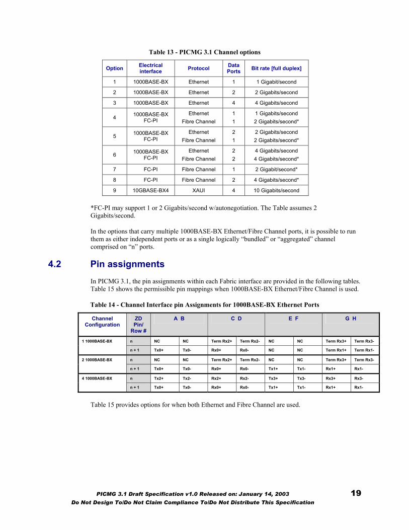
Table 13 - PICMG 3.1 Channel options
Option Electrical interface Protocol Data
Ports Bit rate [full duplex]
1 1000BASE-BX Ethernet 1 1 Gigabit/second
2 1000BASE-BX Ethernet 2 2 Gigabits/second
3 1000BASE-BX Ethernet 4 4 Gigabits/second
4 1000BASE-BX FC-PI
Ethernet Fibre Channel
1 1
1 Gigabits/second 2 Gigabits/second*
5 1000BASE-BX FC-PI
Ethernet Fibre Channel
2 1
2 Gigabits/second 2 Gigabits/second*
6 1000BASE-BX FC-PI
Ethernet Fibre Channel
2 2
4 Gigabits/second 4 Gigabits/second*
7 FC-PI Fibre Channel 1 2 Gigabit/second*
8 FC-PI Fibre Channel 2 4 Gigabits/second*
9 10GBASE-BX4 XAUI 4 10 Gigabits/second
*FC-PI may support 1 or 2 Gigabits/second w/autonegotiation. The Table assumes 2 Gigabits/second.
In the options that carry multiple 1000BASE-BX Ethernet/Fibre Channel ports, it is possible to run them as either independent ports or as a single logically “bundled” or “aggregated” channel comprised on “n” ports.
4.2 Pin assignments In PICMG 3.1, the pin assignments within each Fabric interface are provided in the following tables. Table 15 shows the permissible pin mappings when 1000BASE-BX Ethernet/Fibre Channel is used.
Table 14 - Channel Interface pin Assignments for 1000BASE-BX Ethernet Ports
Channel Configuration
ZD Pin/
Row #
A B C D E F G H
n NC NC Term Rx2+ Term Rx2- NC NC Term Rx3+ Term Rx3- 1 1000BASE-BX n + 1 Tx0+ Tx0- Rx0+ Rx0- NC NC Term Rx1+ Term Rx1-
n NC NC Term Rx2+ Term Rx2- NC NC Term Rx3+ Term Rx3- 2 1000BASE-BX
n + 1 Tx0+ Tx0- Rx0+ Rx0- Tx1+ Tx1- Rx1+ Rx1-
n Tx2+ Tx2- Rx2+ Rx2- Tx3+ Tx3- Rx3+ Rx3- 4 1000BASE-BX
n + 1 Tx0+ Tx0- Rx0+ Rx0- Tx1+ Tx1- Rx1+ Rx1-
Table 15 provides options for when both Ethernet and Fibre Channel are used.
PICMG 3.1 Draft Specification v1.0 Released on: January 14, 2003 19 Do Not Design To/Do Not Claim Compliance To/Do Not Distribute This Specification
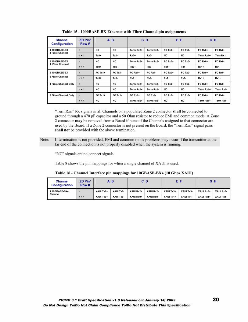
Table 15 - 1000BASE-BX Ethernet with Fibre Channel pin assignments
Channel Configuration
ZD Pin/ Row #
A B C D E F G H
n NC NC Term Rx2+ Term Rx2- FC Tx0+ FC Tx0- FC Rx0+ FC Rx0- 1 1000BASE-BX 1 Fibre Channel
n + 1 Tx0+ Tx0- Rx0+ Rx0- NC NC Term Rx1+ TermRx1-
n NC NC Term Rx2+ Term Rx2- FC Tx0+ FC Tx0- FC Rx0+ FC Rx0- 2 1000BASE-BX 1 Fibre Channel
n + 1 Tx0+ Tx0- Rx0+ Rx0- Tx1+ Tx1- Rx1+ Rx1-
n FC Tx1+ FC Tx1- FC Rx1+ FC Rx1- FC Tx0+ FC Tx0- FC Rx0+ FC Rx0- 2 1000BASE-BX 2 Fibre Channel n + 1 Tx0+ Tx0- Rx0+ Rx0- Tx1+ Tx1- Rx1+ Rx1-
n NC NC Term Rx2+ Term Rx2- FC Tx0+ FC Tx0- FC Rx0+ FC Rx0- 1 Fibre Channel Only
n + 1 NC NC Term Rx0+ Term Rx0- NC NC Term Rx1+ Term Rx1-
n FC Tx1+ FC Tx1- FC Rx1+ FC Rx1- FC Tx0+ FC Tx0- FC Rx0+ FC Rx0- 2 Fibre Channel Only
n + 1 NC NC Term Rx0+ Term Rx0- NC NC Term Rx1+ Term Rx1-
“TermRxn” Rx signals in all Channels on a populated Zone 2 connector shall be connected to ground through a 470 pF capacitor and a 50 Ohm resistor to reduce EMI and common mode. A Zone 2 connector may be removed from a Board if none of the Channels assigned to that connector are used by the Board. If a Zone 2 connector is not present on the Board, the “TermRxn” signal pairs shall not be provided with the above termination.
Note: If termination is not provided, EMI and common mode problems may occur if the transmitter at the far end of the connection is not properly disabled when the system is running.
“NC” signals are no connect signals.
Table 8 shows the pin mappings for when a single channel of XAUI is used.
Table 16 - Channel Interface pin mappings for 10GBASE-BX4 (10 Gbps XAUI)
Channel Configuration
ZD Pin/ Row #
A B C D E F G H
n XAUI Tx2+ XAUI Tx2- XAUI Rx2+ XAUI Rx2- XAUI Tx3+ XAUI Tx3- XAUI Rx3+ XAUI Rx3- 1 10GBASE-BX4 Channel
n + 1 XAUI Tx0+ XAUI Tx0- XAUI Rx0+ XAUI Rx0- XAUI Tx1+ XAUI Tx1- XAUI Rx1+ XAUI Rx1-
PICMG 3.1 Draft Specification v1.0 Released on: January 14, 2003 20 Do Not Design To/Do Not Claim Compliance To/Do Not Distribute This Specification
5 Backplane physical layer interfaces
Because a PIGMG® 3.1 Channel is designed to support 10 Gigabit Ethernet over 4 Ports, each Port has separate transmit and receive pairs,with each pair capable of handling 3.125 Gbaud signaling rates. Each Port can transport either 1 Gb/s Ethernet data or 1 Gb/s Fibre Channel data. However, if auto negotiation is implemented in the case of FC, the Port can support 2 Gigabits of data.
1000BASE-BX is the PICMG 3.0 electrical specification for transmission of 1 Gb/s Ethernet or 1 Gb/s Fibre Channel encoded data over the backplane.
10GBASE-BX4 is the PICMG 3.0 electrical specification for transmission of the 10 Gb/s XAUI signaling for a backplane environment.
Both 1000BASE-BX and 10GBASE-BX4 are logically PMDs, and they are specified to require minimal logic to implement the PMD function (e.g., I/O drivers and receivers that meet PICMG 3.1 specifications).
For this document, an IEEE 802.3 based nomenclature will be used.
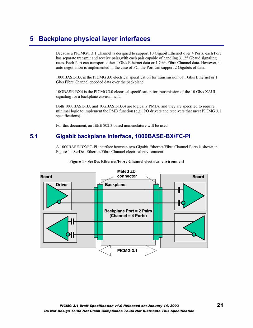
5.1 Gigabit backplane interface, 1000BASE-BX/FC-PI A 1000BASE-BX/FC-PI interface between two Gigabit Ethernet/Fibre Channel Ports is shown in Figure 1 - SerDes Ethernet/Fibre Channel electrical environment.
Figure 1 - SerDes Ethernet/Fibre Channel electrical environment
Driver
Board Mated ZD connector
Backplane
Board
Backplane Port = 2 Pairs (Channel = 4 Ports)
PICMG 3.1
PICMG 3.1 Draft Specification v1.0 Released on: January 14, 2003 21 Do Not Design To/Do Not Claim Compliance To/Do Not Distribute This Specification
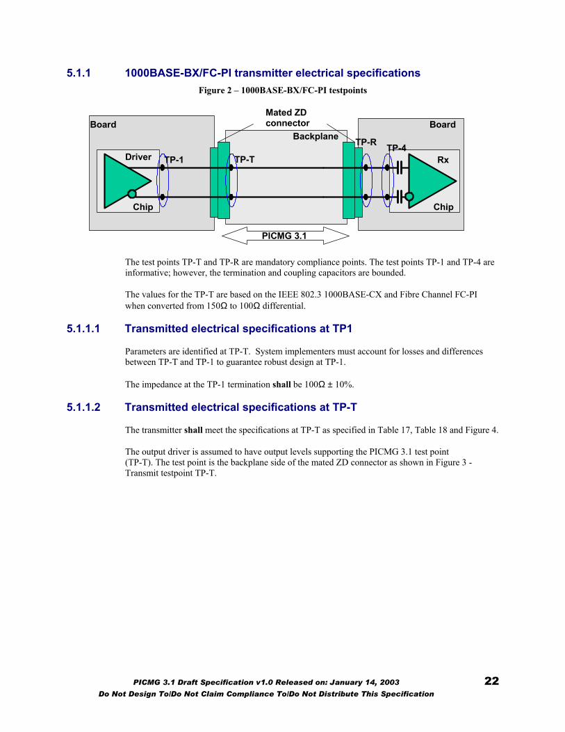
5.1.1 1000BASE-BX/FC-PI transmitter electrical specifications Figure 2 – 1000BASE-BX/FC-PI testpoints
Chip
Board Mated ZD connector
BackplaneBoard
Driver
Chip
Rx TP-1 TP-T
TP-R TP-4
PICMG 3.1
The test points TP-T and TP-R are mandatory compliance points. The test points TP-1 and TP-4 are informative; however, the termination and coupling capacitors are bounded.
The values for the TP-T are based on the IEEE 802.3 1000BASE-CX and Fibre Channel FC-PI when converted from 150Ω to 100Ω differential.
5.1.1.1 Transmitted electrical specifications at TP1
Parameters are identified at TP-T. System implementers must account for losses and differences between TP-T and TP-1 to guarantee robust design at TP-1.
The impedance at the TP-1 termination shall be 100Ω ± 10%.
5.1.1.2 Transmitted electrical specifications at TP-T
The transmitter shall meet the specifications at TP-T as specified in Table 17, Table 18 and Figure 4.
The output driver is assumed to have output levels supporting the PICMG 3.1 test point (TP-T). The test point is the backplane side of the mated ZD connector as shown in Figure 3 - Transmit testpoint TP-T.
PICMG 3.1 Draft Specification v1.0 Released on: January 14, 2003 22 Do Not Design To/Do Not Claim Compliance To/Do Not Distribute This Specification

Figure 3 - Transmit testpoint TP-T
1) Zone 2 connector ground contacts shall be connected to Logic Ground
Note: All traces should be as short as possible
1)
TP-T
Driver
Mated ZDconnector
10nF ±1% 50Ω ±1%
10nF ±1% 50Ω ±1%
Board TP-T Testboard
All specifications are differential.
TDR measurements are recorded times. Recorded time = TDR Transit time * 2.
The transmit differential skew is measured at TP-T between the true and complement signals. This is a single-ended measurement and is measured at the 50% point on the signal swing.
Table 17 - Transmitter specifications at TP-T
Value Description
Ethernet Fibre Channel
Units
Data rate 1000 800* Mb/s
Nominal signaling speed 1250 1062.5* MBd
Clock tolerance ±100 ppm
Differential output amplitude(p-p) 1350 - 750 mV
Return loss 15 dB
Impedance at connection (TP-T) 100 ± 30 Ω
Impedance at termination (TP-1) 100 ± 10 Ω
*FC-PI may support 1 or 2 Gigabits/second w/autonegotiation. The Table assumes 2 Gigabits/second.
Note: All measurements are made though a mated pair connector
components, the maximum drive amplitude of any PICMG 3.1 driver shall not exceed 1600mV P-P.
5.1.1.3 Transmitted eye mask at TP-T
Eye diagram is measured only with high-frequency jitter components that are not tracked by the clock recovery circuit and the lower cutoff frequency for jitter is 637 kHz.
PICMG 3.1 Draft Specification v1.0 Released on: January 14, 2003 23 Do Not Design To/Do Not Claim Compliance To/Do Not Distribute This Specification
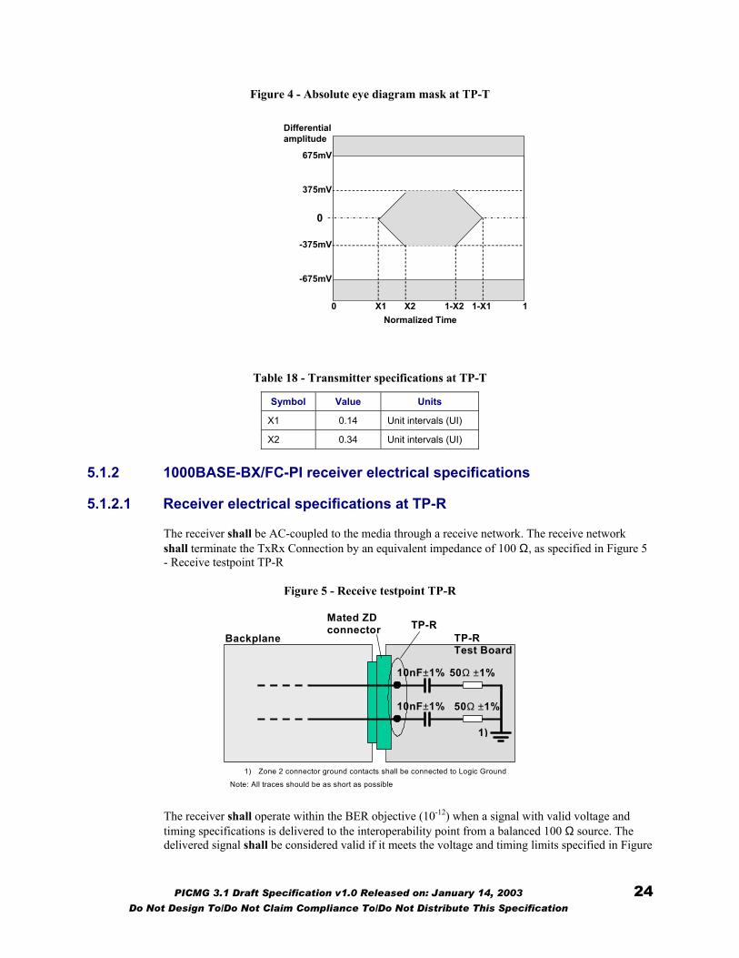
Figure 4 - Absolute eye diagram mask at TP-T
X2
Differential amplitude
Normalized Time 0 1-X1 1 1-X2X1
675mV
-675mV
375mV
-375mV
0
Table 18 - Transmitter specifications at TP-T
Symbol Value Units
X1 0.14 Unit intervals (UI)
X2 0.34 Unit intervals (UI)
5.1.2 1000BASE-BX/FC-PI receiver electrical specifications
5.1.2.1 Receiver electrical specifications at TP-R
The receiver shall be AC-coupled to the media through a receive network. The receive network shall terminate the TxRx Connection by an equivalent impedance of 100 Ω, as specified in Figure 5 - Receive testpoint TP-R
Figure 5 - Receive testpoint TP-R
TP-RMated ZD
connector
10nF±1% 50Ω ±1%
10nF±1% 50Ω ±1%
Backplane TP-R Test Board
1) Zone 2 connector ground contacts shall be connected to Logic Ground
Note: All traces should be as short as possible
1)
The receiver shall operate within the BER objective (10-12) when a signal with valid voltage and timing specifications is delivered to the interoperability point from a balanced 100 Ω source. The delivered signal shall be considered valid if it meets the voltage and timing limits specified in Figure
PICMG 3.1 Draft Specification v1.0 Released on: January 14, 2003 24 Do Not Design To/Do Not Claim Compliance To/Do Not Distribute This Specification
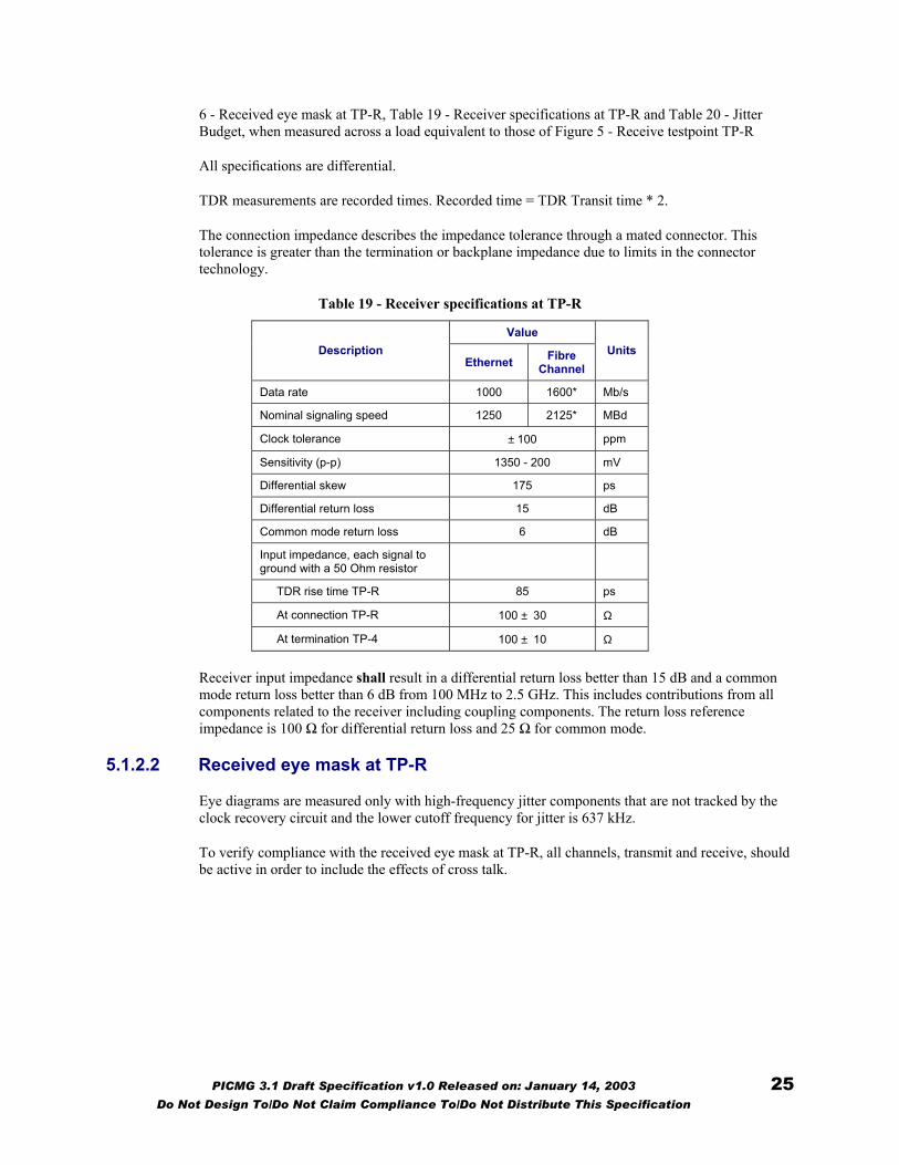
6 - Received eye mask at TP-R, Table 19 - Receiver specifications at TP-R and Table 20 - Jitter Budget, when measured across a load equivalent to those of Figure 5 - Receive testpoint TP-R
All specifications are differential.
TDR measurements are recorded times. Recorded time = TDR Transit time * 2.
The connection impedance describes the impedance tolerance through a mated connector. This tolerance is greater than the termination or backplane impedance due to limits in the connector technology.
Table 19 - Receiver specifications at TP-R
Value Description
Ethernet Fibre Channel
Units
Data rate 1000 1600* Mb/s
Nominal signaling speed 1250 2125* MBd
Clock tolerance ± 100 ppm
Sensitivity (p-p) 1350 - 200 mV
Differential skew 175 ps
Differential return loss 15 dB
Common mode return loss 6 dB
Input impedance, each signal to ground with a 50 Ohm resistor
TDR rise time TP-R 85 ps
At connection TP-R 100 ± 30 Ω
At termination TP-4 100 ± 10 Ω
Receiver input impedance shall result in a differential return loss better than 15 dB and a common mode return loss better than 6 dB from 100 MHz to 2.5 GHz. This includes contributions from all components related to the receiver including coupling components. The return loss reference impedance is 100 Ω for differential return loss and 25 Ω for common mode.
5.1.2.2 Received eye mask at TP-R
Eye diagrams are measured only with high-frequency jitter components that are not tracked by the clock recovery circuit and the lower cutoff frequency for jitter is 637 kHz.
To verify compliance with the received eye mask at TP-R, all channels, transmit and receive, should be active in order to include the effects of cross talk.
PICMG 3.1 Draft Specification v1.0 Released on: January 14, 2003 25 Do Not Design To/Do Not Claim Compliance To/Do Not Distribute This Specification

Figure 6 - Received eye mask at TP-R
Differential am plitude
Norm alized Tim e0 0.7 10.50.3
675m V
-675m V
100m V
-100m V
0
The minimum input amplitude to the receiver listed in Table 20 - Jitter Budget and Figure 6 - Received eye mask at TP-R is a worst case specification across all environmental conditions. Restricted environments may allow operation at lower minimum differential voltages, allowing significantly longer operating distances.
5.1.2.3 Receiver electrical specifications at TP-4
Parameters are identified at TP-R. System implementers must account for losses and differences between TP-R and TP-4 to guarantee robust design at TP-4..
The AC coupling capacitors at the receiver shall be no more than 10 nF +1% and matched within 2% with each other. Each signal is measured to ground with a 50 Ohm resistor.
5.1.3 1000BASE-BX/FC-PI jitter specifications
The PICMG® 3.1 shall meet the total jitter specifications defined in Table 20 - Jitter Budget. Normative values are highlighted in bold. The Deterministic jitter budgetary specifications are shown in Table 12 only for informational purposes to assist implementers in specifying components. Compliance points are TP-T and TP-R as defined in Figure 3 - Transmit testpoint TP-T and Figure 5 - Receive testpoint TP-R.
Deterministic jitter budgetary specifications are included here to assist implementers in specifying components.
Table 20 - Jitter Budget
Total jitter* Deterministic jitter Compliance point UI ps UI ps
TP-T 0.28 223 0.14 112
TP-R 0.66 528 0.4 320
*Total jitter is composed of both deterministic and random components. The allowed random jitter equals the allowed total jitter minus the actual deterministic jitter at that point.
PICMG 3.1 Draft Specification v1.0 Released on: January 14, 2003 26 Do Not Design To/Do Not Claim Compliance To/Do Not Distribute This Specification
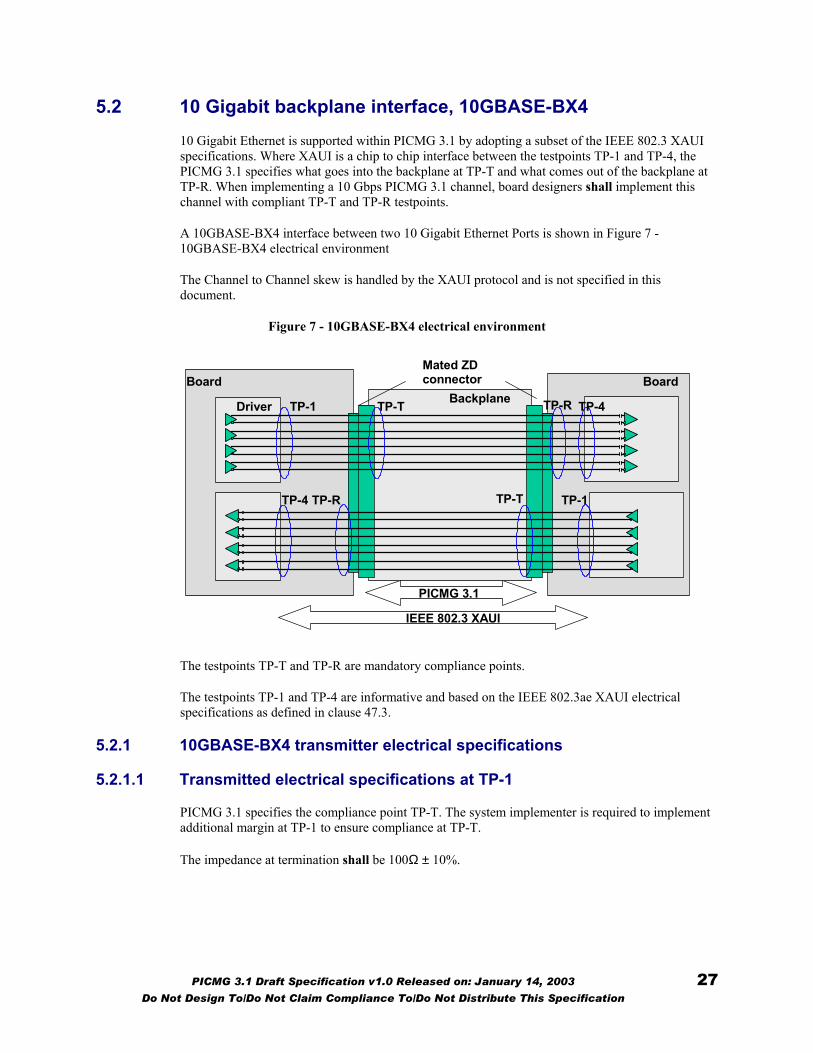
5.2 10 Gigabit backplane interface, 10GBASE-BX4 10 Gigabit Ethernet is supported within PICMG 3.1 by adopting a subset of the IEEE 802.3 XAUI specifications. Where XAUI is a chip to chip interface between the testpoints TP-1 and TP-4, the PICMG 3.1 specifies what goes into the backplane at TP-T and what comes out of the backplane at TP-R. When implementing a 10 Gbps PICMG 3.1 channel, board designers shall implement this channel with compliant TP-T and TP-R testpoints.
A 10GBASE-BX4 interface between two 10 Gigabit Ethernet Ports is shown in Figure 7 - 10GBASE-BX4 electrical environment
The Channel to Channel skew is handled by the XAUI protocol and is not specified in this document.
Figure 7 - 10GBASE-BX4 electrical environment
Driver
Board Mated ZD connector
BackplaneBoard
TP-1 TP-T TP-R TP-4
TP-4 TP-R TP-T TP-1
PICMG 3.1
IEEE 802.3 XAUI
The testpoints TP-T and TP-R are mandatory compliance points.
The testpoints TP-1 and TP-4 are informative and based on the IEEE 802.3ae XAUI electrical specifications as defined in clause 47.3.
5.2.1 10GBASE-BX4 transmitter electrical specifications
5.2.1.1 Transmitted electrical specifications at TP-1
PICMG 3.1 specifies the compliance point TP-T. The system implementer is required to implement additional margin at TP-1 to ensure compliance at TP-T.
The impedance at termination shall be 100Ω ± 10%.
PICMG 3.1 Draft Specification v1.0 Released on: January 14, 2003 27 Do Not Design To/Do Not Claim Compliance To/Do Not Distribute This Specification
5.2.1.2 Transmitted electrical specifications at TP-T
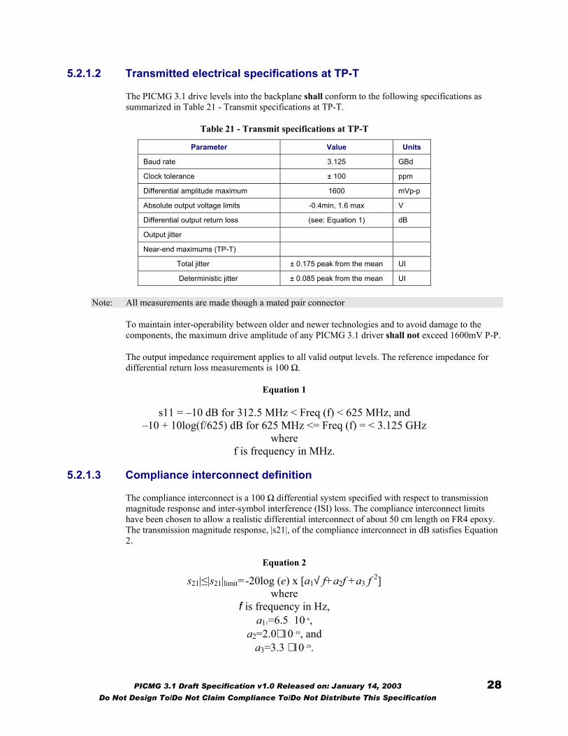
The PICMG 3.1 drive levels into the backplane shall conform to the following specifications as summarized in Table 21 - Transmit specifications at TP-T.
Table 21 - Transmit specifications at TP-T
Parameter Value Units
Baud rate 3.125 GBd
Clock tolerance ± 100 ppm
Differential amplitude maximum 1600 mVp-p
Absolute output voltage limits -0.4min, 1.6 max V
Differential output return loss (see: Equation 1) dB
Output jitter
Near-end maximums (TP-T)
Total jitter ± 0.175 peak from the mean UI
Deterministic jitter ± 0.085 peak from the mean UI
Note: All measurements are made though a mated pair connector
To maintain inter-operability between older and newer technologies and to avoid damage to the components, the maximum drive amplitude of any PICMG 3.1 driver shall not exceed 1600mV P-P.
The output impedance requirement applies to all valid output levels. The reference impedance for differential return loss measurements is 100 Ω.
Equation 1
s11 = –10 dB for 312.5 MHz < Freq (f) < 625 MHz, and –10 + 10log(f/625) dB for 625 MHz <= Freq (f) = < 3.125 GHz
where f is frequency in MHz.
5.2.1.3 Compliance interconnect definition
The compliance interconnect is a 100 Ω differential system specified with respect to transmission magnitude response and inter-symbol interference (ISI) loss. The compliance interconnect limits have been chosen to allow a realistic differential interconnect of about 50 cm length on FR4 epoxy. The transmission magnitude response, |s21|, of the compliance interconnect in dB satisfies Equation 2.
Equation 2
s21|≤|s21|limit=-20log (e) x [a1√ f+a2f +a3 f 2] where
f is frequency in Hz, a11=6.5 10–6,
a2=2.0⋅ 10–10, and a3=3.3 ⋅ 10–20.
PICMG 3.1 Draft Specification v1.0 Released on: January 14, 2003 28 Do Not Design To/Do Not Claim Compliance To/Do Not Distribute This Specification

This limit applies from DC to 3.125 GHz. The magnitude response above 3.125 GHz does not exceed –11.4 dB. The ISI loss, defined as the difference in magnitude response between two frequencies, is greater than 4.0 dB between 312.5 MHz and 1.5625 GHz. The magnitude response and ISI loss limits are illustrated in Figure 8-Compliance interconnect magnitude response and ISI loss.
Figure 8-Compliance interconnect magnitude response and ISI loss
Is211(dB)
0
ISI Loss>4dB
-11.4 Example of a complianceinterconnect
0 5 2 z
5.2.2 10GBAS
A PICMG 3with a BERmeasured to
5.2.2.1 Receive
The input sand Table 2
PICMG 3
Do Not Design To
E
.1 o g
r e
ign2
.1
/D
0.312
-BX4 receiver electric
receiver shall be AC coupledf better than 10-12 with any varound with a 50 Ohm resistor
lectrical specificatio
als shall comply to the eye m- Receiver specifications at TP
Draft Specification v1.0 Re
o Not Claim Compliance To
0.156
al specifications
at or on the receiver chip. Thelid input signal as defined at TP.
ns at TP-R
ask as defined in Figure 9 - TP-R.
leased on: January 14, 2003
/Do Not Distribute This Spec
3.125GH
receiver shall operate -R. Each signal is
-T and TP-R eye mask
29 ification
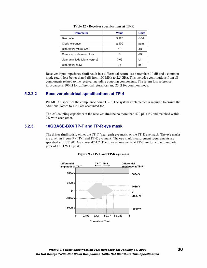
Table 22 - Receiver specifications at TP-R
Parameter Value Units
Baud rate 3.125 GBd
Clock tolerance ± 100 ppm
Differential return loss 10 dB
Common mode return loss 6 dB
Jitter amplitude tolerance(p-p) 0.65 UI
Differential skew 75 ps
Receiver input impedance shall result in a differential return loss better than 10 dB and a common mode return loss better than 6 dB from 100 MHz to 2.5 GHz. This includes contributions from all components related to the receiver including coupling components. The return loss reference impedance is 100 Ω for differential return loss and 25 Ω for common mode.
5.2.2.2 Receiver electrical specifications at TP-4
PICMG 3.1 specifies the compliance point TP-R. The system implementer is required to ensure the additional losses to TP-4 are accounted for.
The AC coupling capacitors at the receiver shall be no more than 470 pF +1% and matched within 2% with each other.
5.2.3 10GBASE-BX4 TP-T and TP-R eye mask
The driver shall satisfy either the TP-T (near-end) eye mask, or the TP-R eye mask. The eye masks are given in Figure 9 - TP-T and TP-R eye mask. The eye mask measurement requirements are specified in IEEE 802.3ae clause 47.4.2. The jitter requirements at TP-T are for a maximum total jitter of ± 0.175 UI peak.
Figure 9 - TP-T and TP-R eye mask
0.42
Differential amplitude at TP-T
Normalized Time
0 1-0.253 11-0.370.192
800mV
-800mV
380mV
-380mV
0
Differential amplitude at TP-R
800mV
-800mV
108mV
-108mV 0
TP-T TP-R
PICMG 3.1 Draft Specification v1.0 Released on: January 14, 2003 30 Do Not Design To/Do Not Claim Compliance To/Do Not Distribute This Specification
PICMG 3.1 Draft Specification v1.0 Released on: January 14, 2003 31 Do Not Design To/Do Not Claim Compliance To/Do Not Distribute This Specification
5.3 Gigabit to 10 gigabit auto negotiation (AN) Fibre Channel, Gigabit Ethernet, and 10GigEthernet operation are treated as separate Channel implementations by electronic keying. PICMG 3.1 does not require or assume any form of auto negotiation or configuration within the Channel between these two signaling interfaces. The out of band electronic keying mechanism defined by PICMG 3.0 manages the configuration of Port/Channel allocations.
Addition of auto negotiation as an in-band negotiation between the two devices on PICMG 3.1 port is dependent on specification of such capability within IEEE 802.3. At the time of publication, no project has been initiated within the 802.3 Working Group to define such a capability.