picbasic pro™ compiler reference manual · thank you for using picbasic pro compiler. the goal of...
TRANSCRIPT
PICBASIC PRO™ Compiler
REFERENCE MANUAL Revised March 6, 2013
Copyright 2013 microEngineering Labs, Inc
www.melabs.com
Please report errors and inaccuracies to [email protected].
Thank you for using PICBASIC PRO Compiler. The goal of this document is to provide accurate and exhaustive information about the workings of the software and how it might be used. As development continues in the software, so shall this manual receive frequent revision. The latest manual release is available for download at http://PBP3.com.
Legal stuff:
microEngineering labs, inc. (the company) disclaims all warranties, express or implied, including without limitation the implied warranty of fitness for a particular purpose, the implied warranty of merchantability, and the implied warranty of the accuracy of the information presented in this document. In no event shall the company or its employees, agents, suppliers or contractors be liable for any incidental, indirect, special or consequential damages arising out of or in connection with the use of the products described herein, including without limitation, lost profits, downtime, goodwill, damage to or replacement of equipment or property, or any costs for recovering, reprogramming or reproducing any data used with the products.
PIC, PICmicro, dsPIC, and MPLAB are registered trademarks of Microchip Technology Inc. in the USA and other countries. MPASM, PICkit, PICBASIC, PICBASIC PRO, PICPROTO, and EPIC are trademarks of Microchip Technology Inc. in the USA and other countries. BASIC Stamp is a trademark of Parallax, Inc.

PICBASIC PRO™ Compiler REFERENCE MANUAL
Table of Contents
4 www.melabs.com 2013-03-06
Table of Contents
Chapter 1: Vital Information ........................................................................... 11 1.1 System Overview .................................................................................. 12 1.2 Integrated Development Environment (IDE) ......................................... 14
1.2.1 MPLAB ......................................................................................... 14 1.2.2 MicroCode Studio ........................................................................ 14 1.2.3 Other IDEs ................................................................................... 14
1.3 Compile Modes PBPW and PBPL ........................................................ 15 1.4 Microchip Datasheets ........................................................................... 16 1.5 Microchip Nomenclature ....................................................................... 17 1.6 Manual Conventions and Notes ............................................................ 18
1.6.1 Command Prototypes .................................................................. 18 1.6.2 Special Terminology and Acronyms ............................................. 19 1.6.3 Number formats ........................................................................... 19 1.6.4 Comments in code examples ....................................................... 19
1.7 Technical Support ................................................................................. 20 1.7.1 Support Requirements ................................................................. 20
Chapter 2: PBP Syntax and Programming .................................................... 21 2.1 Program Organization (Example) ......................................................... 22 2.2 I/O Pins ................................................................................................. 23
2.2.1 Data Direction .............................................................................. 23 2.2.2 Aliasing ........................................................................................ 23 2.2.3 Use in High-Level Commands ..................................................... 24 2.2.4 Additional Configuration ............................................................... 24 2.2.5 Pin Characteristics ....................................................................... 25
2.3 DEFINEs ............................................................................................... 26 2.3.1 DEFINE OSC ............................................................................... 26 2.3.2 Global DEFINEs ........................................................................... 27 2.3.3 DEFINEs defined ......................................................................... 27
2.4 Aliases .................................................................................................. 29 2.5 Labels ................................................................................................... 31 2.6 Variables ............................................................................................... 32
2.6.1 Creating Scalar Variables ............................................................ 32 2.6.2 Creating Array Variables .............................................................. 34 2.6.3 Using Scalar Variables ................................................................. 34 2.6.4 Using Array Variables .................................................................. 37
2.7 Constants ............................................................................................. 39 2.8 Modifiers ............................................................................................... 40
2.8.1 Modifiers used when creating variables ....................................... 40 2.8.2 Modifiers that access binary subsets of numeric values .............. 40 2.8.3 Modifiers for parsing and formatting ASCII strings ....................... 40

PICBASIC PRO™ Compiler REFERENCE MANUAL
Table of Contents
2013-03-06 www.melabs.com 5
2.8.4 Modifiers for specifying variable types in data space .................... 41 2.9 ASCII and Strings .................................................................................. 42 2.10 Input Modifiers for Parsing Strings ......................................................... 44
2.10.1 DEC .............................................................................................. 44 2.10.2 BIN ................................................................................................ 45 2.10.3 HEX .............................................................................................. 46 2.10.4 SKIP .............................................................................................. 47 2.10.5 STR ............................................................................................... 47 2.10.6 WAIT ............................................................................................. 48 2.10.7 WAITSTR ...................................................................................... 49
2.11 Output Modifiers for Formatting Strings ................................................. 51 2.11.1 DEC .............................................................................................. 51 2.11.2 BIN ................................................................................................ 53 2.11.3 HEX .............................................................................................. 54 2.11.4 REP .............................................................................................. 56 2.11.5 STR ............................................................................................... 56
2.12 Numbers ................................................................................................ 58 2.13 Registers ............................................................................................... 59 2.14 Comments ............................................................................................. 60 2.15 Case Sensitivity ..................................................................................... 61
2.15.1 DEFINEs ....................................................................................... 61 2.15.2 Variables ....................................................................................... 61
2.16 White Space .......................................................................................... 62 2.16.1 Tabbing For Readability ................................................................ 63
2.17 Line-Extension ( _ ) ............................................................................... 64 2.18 Line-Concatenation ( : ) ......................................................................... 65 2.19 INCLUDE ............................................................................................... 66
Chapter 3: Operators ...................................................................................... 67 3.1 Math Operators ...................................................................................... 71
3.1.1 Multiplication ................................................................................. 71 3.1.2 '*/' and '**' Special Multiplication ................................................. 72 3.1.3 Division ......................................................................................... 73 3.1.4 Remainder (Modulus) ................................................................... 73 3.1.5 ABS ............................................................................................... 74 3.1.6 ATN ............................................................................................... 74 3.1.7 COS .............................................................................................. 74 3.1.8 DCD .............................................................................................. 74 3.1.9 DIG ............................................................................................... 74 3.1.10 DIV32 ............................................................................................ 75 3.1.11 HYP .............................................................................................. 76 3.1.12 MAX and MIN ............................................................................... 76 3.1.13 NCD .............................................................................................. 77

PICBASIC PRO™ Compiler REFERENCE MANUAL
Table of Contents
6 www.melabs.com 2013-03-06
3.1.14 REV.............................................................................................. 77 3.1.15 SIN ............................................................................................... 77 3.1.16 SQR ............................................................................................. 77
3.2 Bitwise Operators ................................................................................. 78 3.2.1 & Bitwise AND ............................................................................. 79 3.2.2 | Bitwise OR ................................................................................ 79 3.2.3 ^ Bitwise EXCLUSIVE OR (XOR) ............................................... 79 3.2.4 ~ Bitwise NOT (INVERT) ............................................................ 80 3.2.5 &/ Bitwise NOT AND (NAND) ...................................................... 80 3.2.6 |/ Bitwise NOT OR (NOR) ........................................................... 81 3.2.7 ^/ Bitwise NOT EXCLUSIVE OR (XNOR) ................................... 81 3.2.8 << SHIFT LEFT ........................................................................... 82 3.2.9 >> SHIFT RIGHT ........................................................................ 83
3.3 Comparison Operators ......................................................................... 84 3.3.1 Signed vs. Unsigned Comparisons .............................................. 84 3.3.2 Equal To ( = or == ) ...................................................................... 85 3.3.3 Not Equal To ( <> or != ) .............................................................. 85 3.3.4 Less Than ( < ) ............................................................................. 85 3.3.5 Greater Than ( > ) ........................................................................ 85 3.3.6 Less Than or Equal To ( <= ) ....................................................... 86 3.3.7 Greater Than or Equal To ( => ) ................................................... 86
3.4 Logical Operators ................................................................................. 87 3.4.1 Using Parentheses ....................................................................... 87 3.4.2 Logical vs. Bitwise ........................................................................ 87 3.4.3 AND ............................................................................................. 88 3.4.4 OR ............................................................................................... 88 3.4.5 XOR ............................................................................................. 88 3.4.6 NOT ............................................................................................. 89 3.4.7 ANDNOT ...................................................................................... 89 3.4.8 ORNOT ........................................................................................ 89 3.4.9 XORNOT ...................................................................................... 89
Chapter 4: Directives ..................................................................................... 90 4.1 DISABLE .............................................................................................. 92 4.2 DISABLE DEBUG ................................................................................. 93 4.3 DISABLE INTERRUPT ......................................................................... 94 4.4 ENABLE ............................................................................................... 95 4.5 ENABLE DEBUG .................................................................................. 96 4.6 ENABLE INTERRUPT .......................................................................... 97 4.7 ON DEBUG........................................................................................... 98 4.8 ON INTERRUPT ................................................................................... 99 4.9 #CONFIG...#ENDCONFIG ................................................................. 100 4.10 #DEFINE ............................................................................................ 102
PICBASIC PRO™ Compiler REFERENCE MANUAL
Table of Contents
2013-03-06 www.melabs.com 7
4.11 #ERROR.............................................................................................. 104 4.12 #IF…#ELSE…#ENDIF ........................................................................ 105 4.13 #IFDEF…#ELSE…#ENDIF ................................................................. 107 4.14 #IFNDEF…#ELSE…#ENDIF ............................................................... 108 4.15 #MSG .................................................................................................. 109 4.16 #WARNING ......................................................................................... 110
Chapter 5: Commands ................................................................................. 111 5.1 Overview of Commands ...................................................................... 112 5.2 @ ......................................................................................................... 115 5.3 ADCIN ................................................................................................. 116 5.4 ARRAYREAD ...................................................................................... 118 5.5 ARRAYWRITE ..................................................................................... 119 5.6 ASM..ENDASM ................................................................................... 120 5.7 BRANCH ............................................................................................. 121 5.8 BRANCHL ........................................................................................... 122 5.9 BUTTON .............................................................................................. 123 5.10 CALL ................................................................................................... 126 5.11 CLEAR................................................................................................. 127 5.12 CLEARWDT ........................................................................................ 128 5.13 COUNT ................................................................................................ 129 5.14 DATA ................................................................................................... 130 5.15 DEBUG ................................................................................................ 131 5.16 DEBUGIN ............................................................................................ 133 5.17 DO..LOOP ........................................................................................... 136 5.18 DTMFOUT ........................................................................................... 138 5.19 EEPROM ............................................................................................. 139 5.20 END ..................................................................................................... 140 5.21 ERASECODE ...................................................................................... 141 5.22 EXIT .................................................................................................... 142 5.23 FOR..NEXT ......................................................................................... 143 5.24 FREQOUT ........................................................................................... 144 5.25 GOSUB................................................................................................ 145 5.26 GOTO .................................................................................................. 146 5.27 HIGH ................................................................................................... 147 5.28 HPWM ................................................................................................. 148 5.29 HSERIN ............................................................................................... 150 5.30 HSERIN2 ............................................................................................. 153 5.31 HSEROUT ........................................................................................... 154 5.32 HSEROUT2 ......................................................................................... 156 5.33 I2CREAD ............................................................................................. 157 5.34 I2CWRITE ........................................................................................... 161 5.35 IF..THEN.............................................................................................. 164

PICBASIC PRO™ Compiler REFERENCE MANUAL
Table of Contents
8 www.melabs.com 2013-03-06
5.36 INPUT ................................................................................................. 166 5.37 LCDIN ................................................................................................. 167 5.38 LCDOUT ............................................................................................. 168 5.39 {LET} ................................................................................................... 174 5.40 LOOKDOWN ...................................................................................... 175 5.41 LOOKDOWN2 .................................................................................... 176 5.42 LOOKUP ............................................................................................. 177 5.43 LOOKUP2 ........................................................................................... 178 5.44 LOW ................................................................................................... 179 5.45 NAP .................................................................................................... 180 5.46 ON GOSUB ........................................................................................ 182 5.47 ON GOTO ........................................................................................... 183 5.48 OUTPUT ............................................................................................. 184 5.49 OWIN .................................................................................................. 185 5.50 OWOUT .............................................................................................. 186 5.51 PAUSE ............................................................................................... 187 5.52 PAUSEUS........................................................................................... 188 5.53 PEEK .................................................................................................. 189 5.54 PEEKCODE ........................................................................................ 190 5.55 POKE .................................................................................................. 191 5.56 POKECODE ....................................................................................... 192 5.57 POT .................................................................................................... 193 5.58 PULSIN ............................................................................................... 195 5.59 PULSOUT ........................................................................................... 196 5.60 PWM ................................................................................................... 197 5.61 RANDOM ............................................................................................ 198 5.62 RCTIME .............................................................................................. 199 5.63 READ .................................................................................................. 200 5.64 READCODE ....................................................................................... 201 5.65 REPEAT..UNTIL ................................................................................. 202 5.66 RESUME ............................................................................................ 203 5.67 RETURN ............................................................................................. 204 5.68 REVERSE........................................................................................... 205 5.69 SELECT CASE ................................................................................... 206 5.70 SERIN ................................................................................................. 207 5.71 SERIN2 ............................................................................................... 209 5.72 SEROUT ............................................................................................. 213 5.73 SEROUT2 ........................................................................................... 215 5.74 SHIFTIN .............................................................................................. 219 5.75 SHIFTOUT .......................................................................................... 222 5.76 SLEEP ................................................................................................ 224 5.77 SOUND ............................................................................................... 225
PICBASIC PRO™ Compiler REFERENCE MANUAL
Table of Contents
2013-03-06 www.melabs.com 9
5.78 STOP ................................................................................................... 226 5.79 SWAP .................................................................................................. 227 5.80 TOGGLE.............................................................................................. 228 5.81 USBIN.................................................................................................. 229 5.82 USBINIT .............................................................................................. 230 5.83 USBOUT.............................................................................................. 231 5.84 USBSERVICE ..................................................................................... 232 5.85 WHILE..WEND .................................................................................... 233 5.86 WRITE ................................................................................................. 234 5.87 WRITECODE ....................................................................................... 235 5.88 XIN ...................................................................................................... 237 5.89 XOUT................................................................................................... 239
Chapter 6: Interrupts ..................................................................................... 242 6.1 Interrupts Using ON INTERRUPT ....................................................... 244
6.1.1 In Practice ................................................................................... 244 6.1.2 How ON INTERRUPT Works ...................................................... 246
6.2 Interrupts Using Assembly Language .................................................. 248 6.2.1 Checklist ..................................................................................... 248 6.2.2 DEFINEs ..................................................................................... 249 6.2.3 Enabling Interrupts ...................................................................... 249 6.2.4 Placement of the Assembly Language Routine .......................... 249 6.2.5 Declaring Special Variables to Save Context .............................. 250 6.2.6 Access to PBP Variables from the Interrupt Handler .................. 250 6.2.7 Time-Sensitive PBP Commands ................................................. 251
6.3 Assembly Interrupts for PIC18 Devices ............................................... 252 6.3.1 Interrupt Priorities........................................................................ 252 6.3.2 Saving and Restoring Context .................................................... 253 6.3.3 Example High/Low Priority ISR Framework for PIC18 ................ 255
6.4 Assembly Interrupts for Enhanced 14-Bit Instruction Set .................... 256 6.4.1 Saving and Restoring Context .................................................... 256 6.4.2 Example ISR Framework for Enhanced 14-Bit ........................... 256
6.5 Assembly Interrupts for 14-Bit Instruction Set ...................................... 257 6.5.1 Declaring Special Variables to Save Context .............................. 257 6.5.2 Saving and Restoring Context .................................................... 259 6.5.3 Example ISR Framework for the 14-Bit Instruction Set: .............. 261
Chapter 7: Advanced Techniques and Concepts ......................................... 262 7.1 In-Line Assembly Language ................................................................ 263
7.1.1 Inserting Assembly Code ............................................................ 263 7.1.2 Placement of In-line Assembly .................................................... 264
7.2 Code Pages and RAM Banks .............................................................. 266 7.3 RAM Allocation .................................................................................... 268

PICBASIC PRO™ Compiler REFERENCE MANUAL
Table of Contents
10 www.melabs.com 2013-03-06
7.4 MPLAB® Development Environment .................................................. 270 7.4.1 Debugging Tool General Considerations ................................... 270 7.4.2 Debugging Tool Device-Specific Considerations ....................... 270
7.5 Hardware Stack .................................................................................. 273 7.6 Array Handling Mechanism ................................................................. 275
7.6.1 The Danger ................................................................................ 275 7.6.2 Brackets Perform Offsets ........................................................... 276 7.6.3 Sub-Arrays within Arrays ............................................................ 277 7.6.4 Accessing Arrays as Multiple Variable-Types ............................ 277 7.6.5 Applying Offsets to Bits within a Variable or Register ................ 279
Chapter 8: Appendixes ................................................................................ 280 8.1 Debugging and Troubleshooting ......................................................... 281
8.1.1 Configuration .............................................................................. 281 8.1.2 Initializing values ........................................................................ 281 8.1.3 DEFINE OSC ............................................................................. 281 8.1.4 Analog Inputs ............................................................................. 282 8.1.5 Internal Oscillator ....................................................................... 282 8.1.6 Read-Modify-Write ..................................................................... 283 8.1.7 Data Direction ............................................................................ 284 8.1.8 Analog Conversion ..................................................................... 285 8.1.9 I/O pin parameters and limitations ............................................. 286 8.1.10 Piggybacked pin functions ......................................................... 286 8.1.11 Pin Relocation and Defines ........................................................ 286 8.1.12 Omitting parentheses ................................................................. 287 8.1.13 Channel numbers vs. pins .......................................................... 287 8.1.14 Hardware Stack ......................................................................... 288 8.1.15 Overrunning Array Variables ...................................................... 288
8.2 12-Bit Instruction Set Considerations .................................................. 289 8.3 PBPX Command Line Operation ........................................................ 290 8.4 Specifying Assembler Location with PBP_MPASM ............................ 294 8.5 defs Include Files ................................................................................ 295
8.5.1 modedefs.bas ............................................................................ 295 8.5.2 bs1defs.bas ................................................................................ 295 8.5.3 bs2defs.bas ................................................................................ 295
8.6 SERIN2/SEROUT2 Mode List ............................................................ 296 8.7 Defines ............................................................................................... 298 8.8 Reserved Words ................................................................................. 301 8.9 ASCII Conversion Chart ..................................................................... 305 8.10 Glossary ............................................................................................. 307 8.11 Index ................................................................................................... 312
PICBASIC PRO™ Compiler REFERENCE MANUAL
Vital Information
2013-03-06 www.melabs.com 11
Chapter 1: Vital Information

PICBASIC PRO™ Compiler REFERENCE MANUAL
Vital Information
12 www.melabs.com 2013-03-06
1.1 System Overview PICBASIC PRO Compiler (PBP) is intended to be used within a system comprised of several tools. Below is a brief list of commonly used components, listed in the order in which you are likely to encounter them.
Your PBP installation typically includes PICBASIC PRO Compiler, Mecanique's MicroCode Studio IDE, Microchip's MPLAB IDE, and Microchip's MPASM assembler.
If you obtained PBP as a reduced-filesize download, the installation does not include MPLAB and MPASM, but the installation process will offer you the chance to download and install MPLAB. MPLAB includes MPASM. The latest version of MPLAB can always be downloaded from Microchip's website (www.microchip.com)
Integrated Development Environment (IDE)
The IDE is the user-interface, in which you create and edit your program. A good IDE will also manage the following tools, invoking them when needed. Examples of IDEs include MicroCode Studio from Mecanique and MPLAB® from Microchip.
Compiler
The compiler is the tool that converts your BASIC program into Assembly Language. PBP is a compiler. PBP depends on an IDE for user interface, and an assembler to finish the conversion to machine-language.
Assembler
The assembler is the tool that converts the Assembly Language into machine language. The assembler runs after the compiler, and is normally invoked automatically. PBP is designed to use Microchip's MPASM assembler, which is included with MPLAB.

PICBASIC PRO™ Compiler REFERENCE MANUAL
Vital Information
2013-03-06 www.melabs.com 13
Device Programmer
The device programmer takes the machine language code and "burns" it into the microcontroller. Examples of device programmers are the U2 Programmer from melabs and the PICkit™ 3 from Microchip. The melabs U2 Programmer is recommended for ease of use and availability of technical support.
Debugger
A debugger is used to "see" what is happening inside the microcontroller when it runs. The simplest method of debugging is to write bits of code into your program that display information like variable and register values. The term In-Circuit Debugger (ICD) refers to a device or method that gives you step-by-step control of program execution via a connection to the microcontroller. Examples of debuggers are the ICD3 from Microchip and the software-based ICD system offered in MicroCode Studio PLUS from Mecanique.

PICBASIC PRO™ Compiler REFERENCE MANUAL
Vital Information
14 www.melabs.com 2013-03-06
1.2 Integrated Development Environment (IDE) PBP is designed to operate within an Integrated Development Environment (IDE). This means that, by itself, PBP is only a utility that accepts files as inputs and generates files as outputs. The IDE is what provides the user interface and program-editing capability.
1.2.1 MPLAB
Microchip (www.microchip.com) offers a free IDE called MPLAB. It is included on the PBP installation CD. In order to use MPLAB, PBP must be first installed as a language tool within that environment. A utility can be run from the PBP program group on the Start menu that will accomplish the installation and setup.
MPLAB should be installed even if you are using a different IDE. The MPLAB installation includes the Microchip assembler, MPASM, which is needed for operation of PBP.
1.2.2 MicroCode Studio
MicroCode Studio is a purpose-built IDE offered by Mecanique (www.mecanique.co.uk). MicroCode Studio is included on the PBP installation CD. It is a favorite among PBP users for its ease of use.
Mecanique offers an advanced version (MicroCode Studio Plus) that adds features for in-circuit debugging and bootloader programming.
1.2.3 Other IDEs
Any text editor can be used to create programs for PBP, though it is best to use one that is designed with compiler-management capability. Even better is an IDE that is PBP-aware and will highlight PBP syntax with color and text formatting.

PICBASIC PRO™ Compiler REFERENCE MANUAL
Vital Information
2013-03-06 www.melabs.com 15
1.3 Compile Modes PBPW and PBPL Throughout this manual, you will find references to "PBPW" and "PBPL". These represent compilation modes that control the maximum size variable type in PBP. WORD variables are 16-bits wide and can hold values 0 to 65535. LONG variables are 32-bits wide and can hold values -2147483648 to 2147483647.
PBPW refers to "PBP in WORD-mode". In this mode, LONG variables are not available to PBP or to the user. When generating temp variables in the background, PBP will use WORDs to save resources and improve execution speed. This mode is available to all target devices.
PBPL refers to "PBP in LONG-mode". In this mode, LONG variables are made available. This mode is only available when compiling for a target device with the "PIC18" prefix. LONG variables are interpreted as two's-complement, signed values in PBP, whereas other variable types are not. This affects the results of some math and comparison operators.
The mode-selection should be available in the compile or project options within the Integrated Development Environment (IDE) that you have chosen. If you are accessing the executable directly or setting up an IDE that requires command-line information to access the executable, the command-line switch –n invokes PBP in LONG mode.
For more information see:
2.6: Variables 3.1: Math Operators 3.3.1: Signed vs. Unsigned Comparisons 8.3: PBPX Command Line Operation

PICBASIC PRO™ Compiler REFERENCE MANUAL
Vital Information
16 www.melabs.com 2013-03-06
1.4 Microchip Datasheets At the time of this writing, PBP supports more than 500 microcontrollers. Each of these devices has its own set of internal registers that perform specific functions. The names and construction of these registers differ between device families. Some family's internal workings are incredibly powerful and complex. Microchip provides a datasheet for each family that details how things work.
In order to use PBP, you must become familiar with the datasheet for the device you have chosen to use. It isn't necessary to read a datasheet from cover to cover, but the datasheet will provide the reference documentation that is needed to manage the device with PBP.
PBP is a full-fledged, professional-level compiler for embedded development. It is also a tool with a reputation for ease-of-use, suitable to the hobbyist. If you are moving to PBP from a "microcontroller-like" device that didn't require you to use datasheets, then you have stepped up considerably. We congratulate you and we'll do everything possible to help you make the transition.
Datasheets can be found at www.microchip.com. A search of the website using the device part number should turn up the datasheet quickly.
If you need help understanding the datasheet, contact melabs support.
PICBASIC PRO™ Compiler REFERENCE MANUAL
Vital Information
2013-03-06 www.melabs.com 17
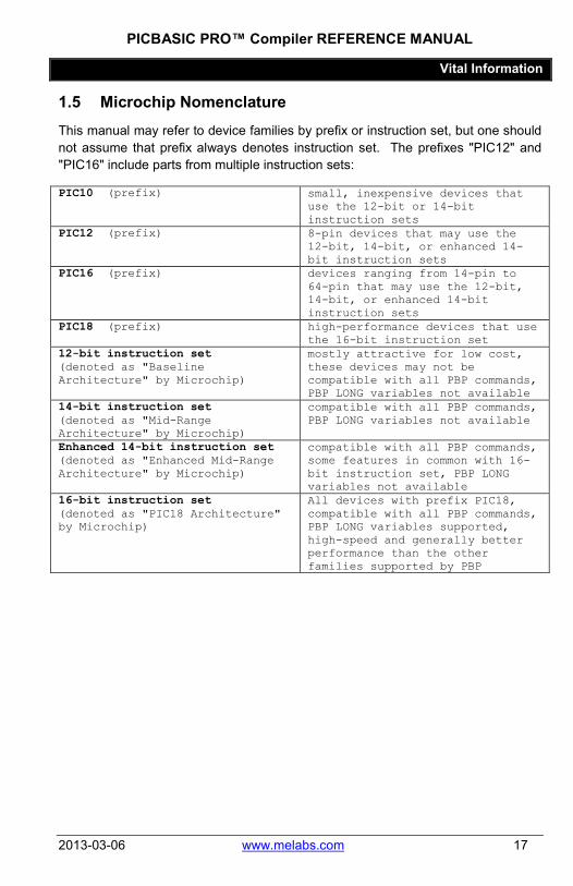
1.5 Microchip Nomenclature This manual may refer to device families by prefix or instruction set, but one should not assume that prefix always denotes instruction set. The prefixes "PIC12" and "PIC16" include parts from multiple instruction sets:
PIC10 (prefix) small, inexpensive devices that use the 12-bit or 14-bit instruction sets
PIC12 (prefix) 8-pin devices that may use the 12-bit, 14-bit, or enhanced 14-bit instruction sets
PIC16 (prefix) devices ranging from 14-pin to 64-pin that may use the 12-bit, 14-bit, or enhanced 14-bit instruction sets
PIC18 (prefix) high-performance devices that use the 16-bit instruction set
12-bit instruction set (denoted as "Baseline Architecture" by Microchip)
mostly attractive for low cost, these devices may not be compatible with all PBP commands, PBP LONG variables not available
14-bit instruction set (denoted as "Mid-Range Architecture" by Microchip)
compatible with all PBP commands, PBP LONG variables not available
Enhanced 14-bit instruction set (denoted as "Enhanced Mid-Range Architecture" by Microchip)
compatible with all PBP commands, some features in common with 16-bit instruction set, PBP LONG variables not available
16-bit instruction set (denoted as "PIC18 Architecture" by Microchip)
All devices with prefix PIC18, compatible with all PBP commands, PBP LONG variables supported, high-speed and generally better performance than the other families supported by PBP

PICBASIC PRO™ Compiler REFERENCE MANUAL
Vital Information
18 www.melabs.com 2013-03-06
1.6 Manual Conventions and Notes
1.6.1 Command Prototypes
Each command will be illustrated with a prototype that shows the required and optional parameters that may be used. The key to reading the prototypes is that anything enclosed in braces ( {}, curly brackets) is optional when writing the command. For example:
HSERIN {ParityLabel,}{Timeout, Label,}[Item{,...}]
This prototype indicates that for the HSERIN command:
{ParityLabel,} A ParityLabel may be optionally inserted followed by a comma.
{Timeout, Label,} A Timeout value and label may be inserted with commas, and that Timeout and Label must be used together.
[ a square bracket must be used to begin the item list Item at least one Item must be inserted {,…} multiple Items may be listed and separated by
commas ] a square bracket must close the item list
PICBASIC PRO™ Compiler REFERENCE MANUAL
Vital Information
2013-03-06 www.melabs.com 19
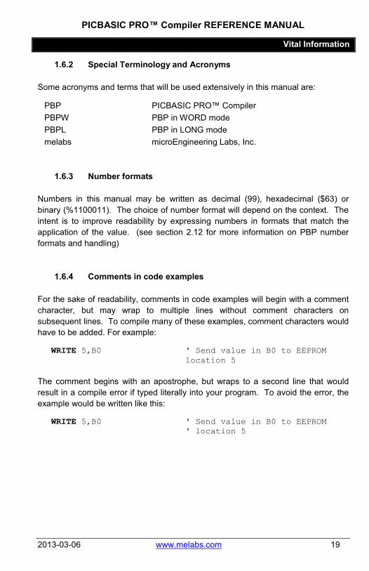
1.6.2 Special Terminology and Acronyms
Some acronyms and terms that will be used extensively in this manual are:
PBP PICBASIC PRO™ Compiler PBPW PBP in WORD mode PBPL PBP in LONG mode melabs microEngineering Labs, Inc.
1.6.3 Number formats
Numbers in this manual may be written as decimal (99), hexadecimal ($63) or binary (%1100011). The choice of number format will depend on the context. The intent is to improve readability by expressing numbers in formats that match the application of the value. (see section 2.12 for more information on PBP number formats and handling)
1.6.4 Comments in code examples
For the sake of readability, comments in code examples will begin with a comment character, but may wrap to multiple lines without comment characters on subsequent lines. To compile many of these examples, comment characters would have to be added. For example:
WRITE 5,B0 ' Send value in B0 to EEPROM location 5
The comment begins with an apostrophe, but wraps to a second line that would result in a compile error if typed literally into your program. To avoid the error, the example would be written like this:
WRITE 5,B0 ' Send value in B0 to EEPROM ' location 5

PICBASIC PRO™ Compiler REFERENCE MANUAL
Vital Information
20 www.melabs.com 2013-03-06
1.7 Technical Support microEngineering Labs takes great pride in providing the best technical support possible. Depending on the PBP edition that you have purchased, tech support is available in different forms.
Online Forum Available for all users Direct Email Available for licensed users of premium editions Telephone Available for licensed users of premium editions
See the Support section of our website (www.melabs.com) for contact details.
1.7.1 Support Requirements
The support we provide can only be as detailed as the information that you provide to us. Please have the following information ready when requesting support.
• PBP version number. • Complete, exact error message, if an error has been encountered. (An
exact error message will usually result in an immediate solution.) • The exact part number of the device you are compiling for. • Complete details about your operating system, including Windows version,
your access privilege level, and whether a virtual machine is in use. • The method that you are using for test/debug. (Hardware platform, ICD
device, running in simulation on PC, etc.)
Please note that reading program code verbally over a telephone connection is our least favorite way of providing support. It just doesn't work. We understand that some users prefer the immediate response of a phone call, but this shouldn't preclude an email with a file attachment. Send us an email, then dial.

PICBASIC PRO™ Compiler REFERENCE MANUAL
PBP Syntax and Programming
2013-03-06 www.melabs.com 21
Chapter 2: PBP Syntax and Programming
PICBASIC PRO™ Compiler REFERENCE MANUAL
PBP Syntax and Programming
22 www.melabs.com 2013-03-06
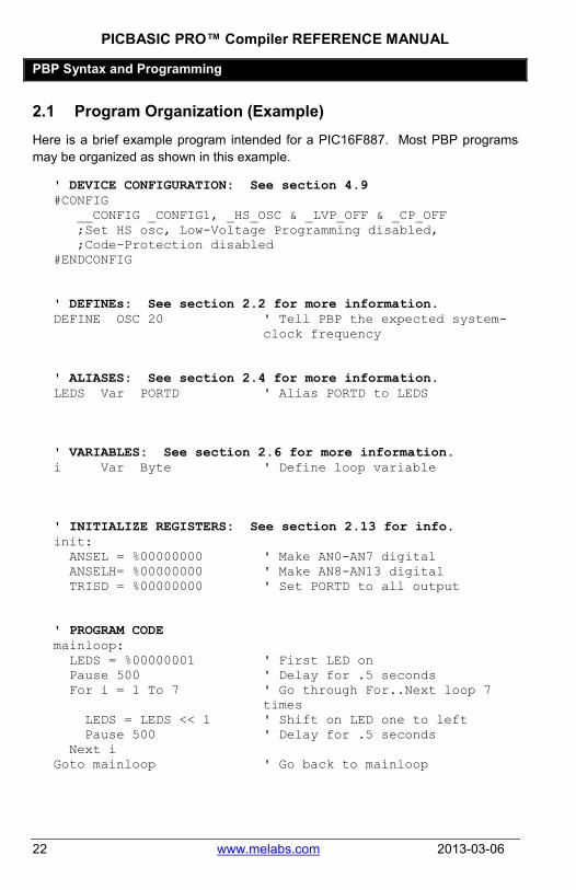
2.1 Program Organization (Example) Here is a brief example program intended for a PIC16F887. Most PBP programs may be organized as shown in this example.
' DEVICE CONFIGURATION: See section 4.9 #CONFIG __CONFIG _CONFIG1, _HS_OSC & _LVP_OFF & _CP_OFF ;Set HS osc, Low-Voltage Programming disabled, ;Code-Protection disabled #ENDCONFIG ' DEFINEs: See section 2.2 for more information. DEFINE OSC 20 ' Tell PBP the expected system-
clock frequency ' ALIASES: See section 2.4 for more information. LEDS Var PORTD ' Alias PORTD to LEDS ' VARIABLES: See section 2.6 for more information. i Var Byte ' Define loop variable ' INITIALIZE REGISTERS: See section 2.13 for info. init: ANSEL = %00000000 ' Make AN0-AN7 digital ANSELH= %00000000 ' Make AN8-AN13 digital TRISD = %00000000 ' Set PORTD to all output ' PROGRAM CODE mainloop: LEDS = %00000001 ' First LED on Pause 500 ' Delay for .5 seconds For i = 1 To 7 ' Go through For..Next loop 7
times LEDS = LEDS << 1 ' Shift on LED one to left Pause 500 ' Delay for .5 seconds Next i Goto mainloop ' Go back to mainloop

PICBASIC PRO™ Compiler REFERENCE MANUAL
PBP Syntax and Programming
2013-03-06 www.melabs.com 23
2.2 I/O Pins The input/output pins on a PIC microcontroller are accessed as bits within a port register (SFR). Port registers may be named PORTx (x being the port letter) or GPIO. The fundamental method for accessing pins is via Direct-Register-Access using the port register name and bit number:
PORTB.2 = 1 ' Set PORTB, bit-2 high x = PORTC.0 ' Read PORTC bit-0 into var x
2.2.1 Data Direction
Most pins on the microcontroller can be configured as input or output. In most cases, they will default to input. To specify the data-direction (input or output), a register is provided in which each bit controls the data-direction of a corresponding I/O pin. These data-direction registers are usually named TRISx (x being the port letter). Smaller devices may use the name TRISIO. In most cases, setting a data-direction bit to 0 results in an output pin, setting to 1 results in an input pin. You should always consult the datasheet for the specific device to be sure.
To expand the example above, each of the pins needs to be configured appropriately as input or output.
TRISB.2 = 0 ' Set PORTB.2 to output TRISC.0 = 1 ' Set PORTC.0 to input PORTB.2 = 1 ' Set PORTB, bit-2 high x = PORTC.0 ' Read PORTC bit-0 into var x
Another commonly-used method is to set the data-direction registers with 8-bit values instead of setting each pin individually:
TRISB = %11111011 ' PORTB.2 output, the rest of PORTB is input
TRISC = %11111111 ' All pins on PORTC are inputs
2.2.2 Aliasing
The above examples demonstrate the low-level method for setting data-direction, but hard-coding the actual PORT.BIT names into the program code will make it difficult to reassign pins at a later date. The accepted method of PBP programming is to assign friendly, meaningful names to the pins and use the assigned names in

PICBASIC PRO™ Compiler REFERENCE MANUAL
PBP Syntax and Programming
24 www.melabs.com 2013-03-06
the program code. These names are known as aliases. See section 2.4 Aliases for more information.
2.2.3 Use in High-Level Commands
The data-direction is set automatically for most of the PBP high-level commands. If the command sends output, the pin is set for output. If the command reads the digital state of the pin, the pin will be set to input. PBP does not set the data-direction back to its original state after such commands are executed.
Either the PORT.PIN designations or the aliases you have assigned may be used directly in PBP commands. For instance, there is no need to read a pin value to a variable before testing it. You can test an input pin directly with:
IF switch = 0 THEN ' Check state of switch pin HIGH led1 ' LED on PAUSE 500 ' Delay 500mS LOW led1 ' LED off ENDIF I2CREAD PORTB.5, PORTB.4, $A0, location,[B_val]
Note the use of the HIGH and LOW commands in the preceding example. These are considered high-level commands because they do more than just set the bit in the PORTx register. They also set the data-direction to output.
2.2.4 Additional Configuration
Setting data-direction does not otherwise configure the pin for analog or digital operation. If analog inputs are to be used, or if an analog input needs to be configured for digital operation, this must be done manually by setting the appropriate registers. See section 8.1.4 Analog Inputs for more information.
Most pins will have several functions that can be enabled/disabled with register settings. Watch out for functions that are enabled by default and that will interfere with digital operation. The analog conversion inputs mentioned above are a good example of this. It is common to have to disable analog functions on pins in order to use them for digital I/O.

PICBASIC PRO™ Compiler REFERENCE MANUAL
PBP Syntax and Programming
2013-03-06 www.melabs.com 25
2.2.5 Pin Characteristics
Microchip provides several types of I/O pins on most devices. You should consult the datasheet when in the design stage to make sure that you choose appropriate pins. Here are some clues:
• Most pins will source 20-25mA of current, but not all. Some, especially on high pin-count devices, will be limited to 2mA per pin.
• In most cases, the total current that a port can supply is limited. In other words, the sum of the current supplied by all the pins on a single port has a limit that supersedes the individual pin limits. In many cases, each pin is limited to 25mA, but the sum of the eight pins on the port is limited to 125mA.
• There are several different types of input pins (Schmidt, CMOS, TTL, etc.) that each have different threshold voltage characteristics.
• Some pins are designated input-only and cannot be used as outputs. • Some pins may be "open-drain" output types, meaning that they can't
source current (drive voltage high). They can only sink current (drive voltage low).
• If a pin is capable of functioning as an input for an analog converter or comparator, it will usually be configured as an analog input by default. These pins must be reconfigured in order to use them as digital I/O.

PICBASIC PRO™ Compiler REFERENCE MANUAL
PBP Syntax and Programming
26 www.melabs.com 2013-03-06
2.3 DEFINEs The DEFINE keyword in PBP is used to set parameters for compilation and assembly. This should not be confused with #DEFINE, which is used for conditional compilation. Further explanation of DEFINE and how it works can be found at the end of this section.
Only a few of the many DEFINE terms will be mentioned here. The rest are associated with PBP commands and will be discussed on the appropriate command pages.
2.3.1 DEFINE OSC
The most important DEFINE in PBP is:
DEFINE OSC 4 ' Oscillator speed in MHz: 3(3.58) 4 8 10 12 16 20 24 25 32 33 40 48 64
In this DEFINE, OSC is set to a number that represents the anticipated system clock frequency in MHz. DEFINE OSC is used extensively by PBP to convert time values to instruction cycles. Any time-critical operation like a pause or a generated baud rate is completely dependent on DEFINE OSC.
Note that each PIC MCU has a specified maximum frequency of operation. The higher frequencies that are available to PBP may not be useable on the device you have chosen. Check the datasheet for the max frequency rating.
If DEFINE OSC is omitted, PBP assumes a default value of DEFINE OSC 4 and calculates based on a 4MHz system clock.
There are a limited number of valid numbers that can be used: 3 (3.58MHz), 4, 8, 10, 12, 16, 20, 24, 25, 32, 33, 40, 48, 64. These are the only frequencies for which PBP is able to accurately calibrate its timing. If you use a system clock that runs at a frequency that isn't listed here, your timing will be scaled when the program executes.
For example, let's assume that you have a good reason to use a 9MHz crystal to clock your MCU. Using "DEFINE OSC 10" will result in your timing to be scaled on the slow side, because the actual clock will run at 90% of the DEFINEd value. A "PAUSE 10" will pause for 11.1mS. Your 9600 baud serial commands will run at 8640 baud.

PICBASIC PRO™ Compiler REFERENCE MANUAL
PBP Syntax and Programming
2013-03-06 www.melabs.com 27
Note that "DEFINE OSC" doesn't set or change the actual clock frequency. It only tells PBP what to expect. The actual frequency is set by selecting a crystal, changing the device configuration, setting registers in your program, or (most commonly) a combination of all of these.
2.3.2 Global DEFINEs
Other DEFINEs that are important, though less frequently used, are:
DEFINE NO_CLRWDT 1 'Don’t insert CLRWDTs DEFINE LOADER_USED 1 'Bootloader is being used DEFINE OSCCAL_1K 1 'Set OSCCAL for 1K PIC12 DEFINE OSCCAL_2K 1 'Set OSCCAL for 2K PIC12 DEFINE RESET_ORG 0h 'Change reset address for PIC18 DEFINE INTHAND Label 'Assign assembler interrupt
handler label DEFINE INTLHAND Label 'Assign assembler low priority
interrupt handler label for PIC18
See section 8.6 for a condensed list of DEFINEs with brief explanations.
2.3.3 DEFINEs defined
For the user familiar with Assembly Language, the major clue to understanding is that DEFINEs in PBP are converted literally to Assembly Language #DEFINE directives.
For the practical PBP user, there are a couple of fundamental points to consider:
1) DEFINEs are CASE SENSITIVE! 2) Specific DEFINEs are generally associated with PBP commands. The
command pages will describe how the relevant DEFINEs affect the operation of each command.
DEFINEs are used by PBP to change the generated Assembly Language that makes up the compiled program. A DEFINE might simply change an internal register setting, or it might result in the use of an alternative Assembly Language routine to accomplish a task.
A good example is in our serial communication commands SEROUT2 and DEBUG. DEBUG uses a DEFINE to set the serial baud rate, while SEROUT2 accepts a baud-rate parameter when the command is executed.

PICBASIC PRO™ Compiler REFERENCE MANUAL
PBP Syntax and Programming
28 www.melabs.com 2013-03-06
The difference is that "DEFINE DEBUG_BAUD 9600" actually causes PBP to find and compile a DEBUG routine that only works at 9600 baud. The SEROUT2 routine is compiled with the capability of working at different baud rates, depending on the parameters passed to it. Since DEBUG is compiled for a specific baud rate, it can't be changed when the program is running. SEROUT2 will accept a variable to set the baud rate on the fly.
Multiple DEFINEs for the same parameter will cause compile/assembly errors in PBP.
It doesn't matter where you place DEFINEs in your code, but it is good practice to keep them together at the top of the program.

PICBASIC PRO™ Compiler REFERENCE MANUAL
PBP Syntax and Programming
2013-03-06 www.melabs.com 29
2.4 Aliases Aliases are simply alternate names for variables, portions of variables, registers, or bits within registers. Alias names are assigned using the VAR keyword.
Alias names should be limited to 31 alpha-numeric characters (letters and numbers) in length. PBP will accept longer names, but all names will be truncated to 31 characters during compilation. Names are not case-sensitive. Names cannot begin with a number. The only special character allowed in names is the underscore "_" character.
long_val VAR LONG 'Variable declarations word_val VAR WORD byte_val VAR BYTE[8] 'Examples of Aliases time VAR long_val speed VAR word_val speed_low VAR word_val.BYTE0 second_byte VAR BYTE[1] data_pin VAR PORTB.3
Aliases are important as a means to make global changes throughout your code, as well as a method for making some names more meaningful. For example, let's take the simple operation of blinking an LED that is connected to a pin:
mainloop: HIGH PORTB.0 PAUSE 500 LOW PORTB.0 PAUSE 500
GOTO mainloop
The above example works, but when someone else reads the code, they will have no idea what is connected to PORTB.0 until they consult the schematic. A more readable method, with no penalty in resources used, is:
PICBASIC PRO™ Compiler REFERENCE MANUAL
PBP Syntax and Programming
30 www.melabs.com 2013-03-06
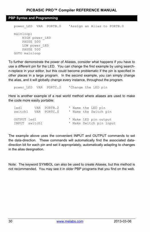
power_LED VAR PORTB.0 'Assign an Alias to PORTB.0 mainloop:
HIGH power_LED PAUSE 500 LOW power_LED PAUSE 500
GOTO mainloop
To further demonstrate the power of Aliases, consider what happens if you have to use a different pin for the LED. You can change the first example by using search-n-replace in your editor, but this could become problematic if the pin is specified in other places in a large program. In the second example, you can simply change the alias, and it will globally change every instance, throughout the program.
power_LED VAR PORTC.2 'Change the LED pin
Here is another example of a real world method where aliases are used to make the code more easily portable:
led1 VAR PORTB.2 ' Name the LED pin switch1 VAR PORTC.0 ' Name the Switch pin OUTPUT led1 ' Make LED pin output INPUT switch1 ' Make Switch pin input
The example above uses the convenient INPUT and OUTPUT commands to set the data-direction. These commands will automatically find the associated data-direction bit for each pin and set it appropriately, automatically adapting to changes in the alias designation.
Note: The keyword SYMBOL can also be used to create Aliases, but this method is not recommended. You may see it in older PBP programs that you find on the web.

PICBASIC PRO™ Compiler REFERENCE MANUAL
PBP Syntax and Programming
2013-03-06 www.melabs.com 31
2.5 Labels Labels are names used to mark a place in a program. Usually, labels are used in conjunction with GOTO, GOSUB or similar commands that need a location to jump to in a program. Labels don't use any resources on the MCU.
Label names should be limited to 31 alpha-numeric characters (letters and numbers) in length. PBP will accept longer names, but all names will be truncated to 31 characters during compilation. Names are not case-sensitive. Names cannot begin with a number. The only special character allowed in names is the underscore "_" character.
Labels should be denoted with a colon afterwards.
mainloop: SEROUT 0,N2400,["Hello, World!",13,10] PAUSE 500
GOTO mainloop

PICBASIC PRO™ Compiler REFERENCE MANUAL
PBP Syntax and Programming
32 www.melabs.com 2013-03-06
2.6 Variables Variables are where temporary data is stored in a PICBASIC PRO program. They are created using the VAR keyword. Variables may be bit-, byte- and word-sized for PBPW, and bit-, byte-, word- and long-sized for PBPL. Space for each variable is automatically allocated in the microcontroller’s RAM by PBP.
Each variable type can be created as a scalar variable, which holds only one value, or an array variable which can hold many values. Assume that any reference to "variables" in this manual means scalar variables.
Variable names should be limited to 31 alpha-numeric characters (letters and numbers) in length. PBP will accept longer names, but all names will be truncated to 31 characters during compilation. Names are not case-sensitive. Names cannot begin with a number. The only special character allowed in names is the underscore "_" character.
2.6.1 Creating Scalar Variables
The format for creating a variable is as follows:
Variable_Name VAR Type {.Modifiers}
Variable_Name is any unique identifier (name), excluding reserved words.
Type is BIT, BYTE, WORD and, for PBPL, LONG.
Type # of bits Range
BIT 1 0 to 1 BYTE 8 0 to 255 WORD 16 0 to 65535 LONG * 32 -2147483648 to
2147483647 * PBPL Only
As the table shows, BIT, BYTE and WORD variables are always unsigned, i.e. positive numbers. LONG variables, which are only available in PBPL, are always signed, two's-complement numbers. They may hold positive or negative values.
PBPL interprets LONG variable types as signed numbers. WORDs, BYTEs, and of course BITs are always interpreted as positive, unsigned integers when used in a PBP math operation.
If the result of an operation could possibly be negative, it should be stored to a long-sized variable type to preserve the sign. If a negative result is placed in a
PICBASIC PRO™ Compiler REFERENCE MANUAL
PBP Syntax and Programming
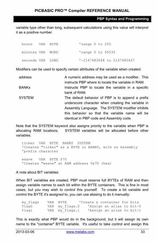
2013-03-06 www.melabs.com 33
variable type other than long, subsequent calculations using this value will interpret it as a positive number.
hours VAR BYTE 'range 0 to 255 minutes VAR WORD 'range 0 to 65535 seconds VAR LONG '-2147483648 to 2147483647
Modifiers can be used to specify certain attributes of the variable when created:
address A numeric address may be used as a modifier. This instructs PBP where to locate the variable in RAM.
BANKx Instructs PBP to locate the variable in a specific bank of RAM.
SYSTEM The default behavior of PBP is to append a prefix underscore character when creating the variable in Assembly Language. The SYSTEM modifier inhibits this behavior so that the variable name will be identical in PBP code and Assembly code.
Note that the SYSTEM keyword also assigns priority to the variable when PBP is allocating RAM locations. SYSTEM variables will be allocated before other variables.
ticker VAR BYTE BANK0 SYSTEM 'Creates "ticker" as a BYTE in BANK0, with no Assembly 'prefix character wsave VAR BYTE $70 'Creates "wsave" at RAM address 0x70 (hex)
A note about BIT variables:
When BIT variables are created, PBP must reserve full BYTEs of RAM and then assign variable names to each bit within the BYTE containers. This is fine in most cases, but you may wish to control this yourself. To create a bit variable and control the BYTE it's assigned to, you can use aliasing to do it manually:
my_flags VAR BYTE 'Create a container for bits flag0 VAR my_flags.0 'Assign an alias to bit-0 flag1 VAR my_flags.1 'Assign an alias to bit-1
This is exactly what PBP would do in the background, but it will assign its own name to the "container" BYTE variable. It's useful to take control and assign this

PICBASIC PRO™ Compiler REFERENCE MANUAL
PBP Syntax and Programming
34 www.melabs.com 2013-03-06
name manually, especially when debugging in an environment that won't show individual bits in a watch window.
2.6.2 Creating Array Variables
Array variables are created using the same syntax as scalar variables, but the number of elements in the array is enclosed in brackets and appended to the variable-type keyword:
samples VAR BYTE[16] 'Create an array of 16 BYTE elements – samples[0] through 'samples[15]
All of the modifiers allowed for scalar variables can also be used for array variables:
samples VAR BYTE[16] BANK3 SYSTEM
Because of the way arrays are accessed and allocated in memory, there are size limits for each type:
Size Maximum Number of elements
PIC18 Devices Other Devices
BIT 256 256 BYTE limited only by
available RAM 96
WORD limited only by available RAM
48
LONG limited only by available RAM
LONGs not available
Arrays must fit entirely within one RAM-bank on 12-bit and 14-bit devices (PIC10, PIC12, and PIC16). Arrays may span banks on PIC18 devices. On PIC18 devices, BYTE, WORD and LONG-sized arrays are only limited in length by the amount of available memory. The compiler will assure that arrays, as well as scalar variables, will fit in memory before successfully compiling.
2.6.3 Using Scalar Variables
Using previously-created variables is straightforward. Simply write variable names in commands or expressions.
Note that PBP is aware of a variable's type and will make decisions based on this. The behavior of certain commands may change based on the type of variables that

PICBASIC PRO™ Compiler REFERENCE MANUAL
PBP Syntax and Programming
2013-03-06 www.melabs.com 35
are used. The underlying math routines will always be tailored to the variable types used for input and result. In most cases, the use of BYTE variables will result in faster-executing code.
B_val VAR BYTE 'Create a BYTE variable location VAR WORD 'Create a WORD variable B_val = PORTB 'Read PORTB into B_val location = 0 'Set location to 0 I2CREAD DPin,CPin,$A0,location,[B_val] 'Read to B_val from a 24LC512 memory chip at location 0
In the example above, the variable-type assigned to "location" affects how the I2CREAD command functions. If the memory was a 24LC01, a BYTE variable would be required.
The smallest variable type in PBP is the BIT. BYTES are made up of BITs, WORDs are made up of BYTES, and LONGs are made up of WORDS. Using modifiers, you can access the smaller entities within a larger variable.
To access bit-7 in a byte variable, you may use "BIT7", or simply "7" after the variable name, separated by a period:
B_val.7 = 1 'Set bit-7 in B_val to 1
To access byte-2 in a LONG variable, use the modifier "BYTE2":
long_val.BYTE2 = 255 'Set byte-2 to 255
The following are all legal in PBP:
long_val VAR LONG word_val VAR WORD byte_val VAR BYTE long_val.WORD1 = 0 long_val.BYTE3 = 255 long_val.31 = 1 word_val.BYTE1 = 0 word_val.15 = 0 byte_val.7 = 0
When using a variable with a modifier, PBP will see the variable-type of the modifier. This can save execution time. For example, you might want to fill a WORD variable by combining the states of registers PORTC and PORTB. It's perfectly valid to write:

PICBASIC PRO™ Compiler REFERENCE MANUAL
PBP Syntax and Programming
36 www.melabs.com 2013-03-06
word_val = (PORTC << 8) + PORTB
But the operation executes faster if you write:
word_val.BYTE1 = PORTC word_val.BYTE0 = PORTB
The following table shows how modifiers refer to "nested" data objects:
Variable Modifiers
LONG
WORD1
BYTE3
BIT31 most-significant-bit (MSB) BIT30
BIT29
BIT28
BIT27
BIT26
BIT25
BIT24
BYTE2
BIT23
BIT22
BIT21
BIT20
BIT19
BIT18
BIT17
BIT16
WORD0
BYTE1*
BIT15
BIT14
BIT13
BIT12
BIT11
BIT10
BIT9
BIT8
BYTE0*
BIT7
BIT6
BIT5
BIT4
BIT3
BIT2
BIT1
BIT0 least-significant-bit (LSB)
* For legacy compatibility, LOWBYTE may be substituted for BYTE0 and HIGHBYTE for BYTE1.
PICBASIC PRO™ Compiler REFERENCE MANUAL
PBP Syntax and Programming
2013-03-06 www.melabs.com 37
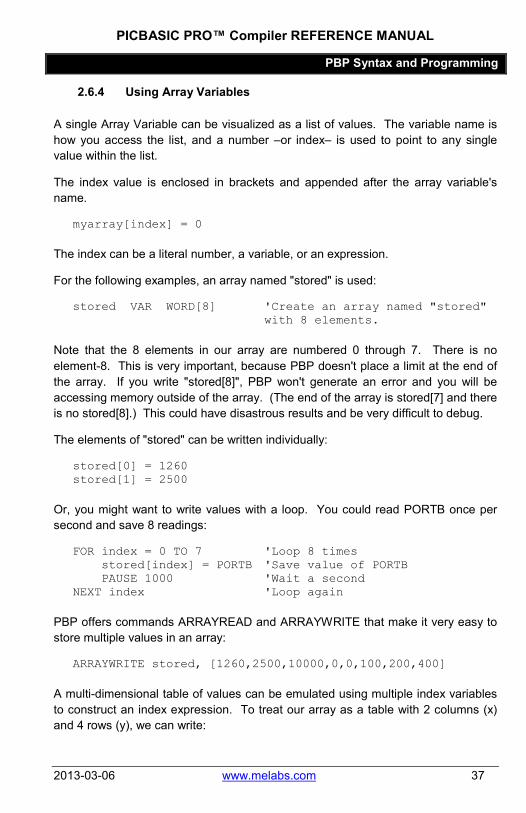
2.6.4 Using Array Variables
A single Array Variable can be visualized as a list of values. The variable name is how you access the list, and a number –or index– is used to point to any single value within the list.
The index value is enclosed in brackets and appended after the array variable's name.
myarray[index] = 0
The index can be a literal number, a variable, or an expression.
For the following examples, an array named "stored" is used:
stored VAR WORD[8] 'Create an array named "stored" with 8 elements.
Note that the 8 elements in our array are numbered 0 through 7. There is no element-8. This is very important, because PBP doesn't place a limit at the end of the array. If you write "stored[8]", PBP won't generate an error and you will be accessing memory outside of the array. (The end of the array is stored[7] and there is no stored[8].) This could have disastrous results and be very difficult to debug.
The elements of "stored" can be written individually:
stored[0] = 1260 stored[1] = 2500
Or, you might want to write values with a loop. You could read PORTB once per second and save 8 readings:
FOR index = 0 TO 7 'Loop 8 times stored[index] = PORTB 'Save value of PORTB PAUSE 1000 'Wait a second
NEXT index 'Loop again
PBP offers commands ARRAYREAD and ARRAYWRITE that make it very easy to store multiple values in an array:
ARRAYWRITE stored, [1260,2500,10000,0,0,100,200,400]
A multi-dimensional table of values can be emulated using multiple index variables to construct an index expression. To treat our array as a table with 2 columns (x) and 4 rows (y), we can write:

PICBASIC PRO™ Compiler REFERENCE MANUAL
PBP Syntax and Programming
38 www.melabs.com 2013-03-06
x = 1 'x points to second column y = 2 'y points to third row stored[(x * 4) + y] = 100 'Write value to location 1,2
In the example above, the x coordinate is multiplied by 4 because we imagine that the array exists as multiple columns that are 4-rows deep. To move across columns in the same row, the actual array index must be incremented by 4.
The following table represents the array in two dimensions. Each location within it shows how the x,y formula results in the actual index value that is used to access the single-dimensional array.
x,y = 0,0 (0 * 4) + 0 = 0
x,y = 1,0 (1 * 4) + 0 = 4
x,y = 0,1 (0 * 4) + 1 = 1
x,y = 1,1 (1 * 4) + 1 = 5
x,y = 0,2 (0 * 4) + 2 = 2
x,y = 1,2 (1 * 4) + 2 = 6
x,y = 0,3 (0 * 4) + 3 = 3
x,y = 1,3 (1 * 4) + 3 = 7
One more note about array variables. The modifiers associated with scalar variables can't be used with array variables:
stored[1].BYTE0 = 0 'ERROR
Instead, a temp variable may be used to manipulate a single byte within the value:
temp_word = stored[1] 'copy the value to a temp temp_word.BYTE0 = 0 'change the temp value stored[1] = temp_word 'update the array value
Advanced techniques may be used to access arrays in many different ways. See section 7.6 Array Handling Mechanism for more information.
PICBASIC PRO™ Compiler REFERENCE MANUAL
PBP Syntax and Programming
2013-03-06 www.melabs.com 39
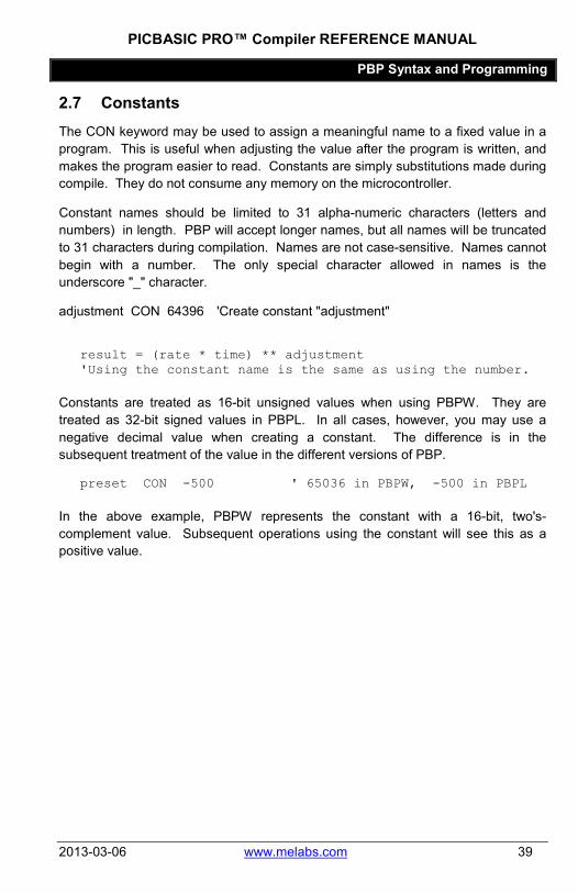
2.7 Constants The CON keyword may be used to assign a meaningful name to a fixed value in a program. This is useful when adjusting the value after the program is written, and makes the program easier to read. Constants are simply substitutions made during compile. They do not consume any memory on the microcontroller.
Constant names should be limited to 31 alpha-numeric characters (letters and numbers) in length. PBP will accept longer names, but all names will be truncated to 31 characters during compilation. Names are not case-sensitive. Names cannot begin with a number. The only special character allowed in names is the underscore "_" character.
adjustment CON 64396 'Create constant "adjustment"
result = (rate * time) ** adjustment 'Using the constant name is the same as using the number.
Constants are treated as 16-bit unsigned values when using PBPW. They are treated as 32-bit signed values in PBPL. In all cases, however, you may use a negative decimal value when creating a constant. The difference is in the subsequent treatment of the value in the different versions of PBP.
preset CON -500 ' 65036 in PBPW, -500 in PBPL
In the above example, PBPW represents the constant with a 16-bit, two's-complement value. Subsequent operations using the constant will see this as a positive value.
PICBASIC PRO™ Compiler REFERENCE MANUAL
PBP Syntax and Programming
40 www.melabs.com 2013-03-06
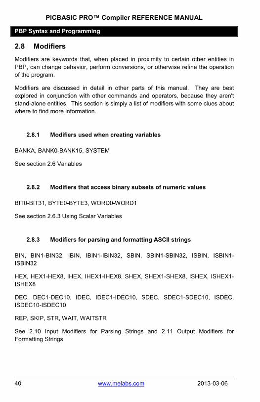
2.8 Modifiers Modifiers are keywords that, when placed in proximity to certain other entities in PBP, can change behavior, perform conversions, or otherwise refine the operation of the program.
Modifiers are discussed in detail in other parts of this manual. They are best explored in conjunction with other commands and operators, because they aren't stand-alone entities. This section is simply a list of modifiers with some clues about where to find more information.
2.8.1 Modifiers used when creating variables
BANKA, BANK0-BANK15, SYSTEM
See section 2.6 Variables
2.8.2 Modifiers that access binary subsets of numeric values
BIT0-BIT31, BYTE0-BYTE3, WORD0-WORD1
See section 2.6.3 Using Scalar Variables
2.8.3 Modifiers for parsing and formatting ASCII strings
BIN, BIN1-BIN32, IBIN, IBIN1-IBIN32, SBIN, SBIN1-SBIN32, ISBIN, ISBIN1-ISBIN32
HEX, HEX1-HEX8, IHEX, IHEX1-IHEX8, SHEX, SHEX1-SHEX8, ISHEX, ISHEX1-ISHEX8
DEC, DEC1-DEC10, IDEC, IDEC1-IDEC10, SDEC, SDEC1-SDEC10, ISDEC, ISDEC10-ISDEC10
REP, SKIP, STR, WAIT, WAITSTR
See 2.10 Input Modifiers for Parsing Strings and 2.11 Output Modifiers for Formatting Strings

PICBASIC PRO™ Compiler REFERENCE MANUAL
PBP Syntax and Programming
2013-03-06 www.melabs.com 41
2.8.4 Modifiers for specifying variable types in data space
Modifiers that specify variable types when passing values to Data Space (EEPROM): (See commands READ, WRITE, DATA, EEPROM)
WORD, LONG
See commands:
5.14 DATA 5.63 READ 5.86 WRITE

PICBASIC PRO™ Compiler REFERENCE MANUAL
PBP Syntax and Programming
42 www.melabs.com 2013-03-06
2.9 ASCII and Strings At some point it will be necessary to work with strings of text in your program. The most common example is to output information on a display. Since PBP has no STRING variable type, you must use special techniques to manipulate strings.
In most commands where strings are likely to be used, PBP will accept literal strings in quotes and handle them appropriately.
HSEROUT ["Hello World"] 'send string "Hello World"
This works for serial communications commands, LCDOUT, ARRAYWRITE, and a few more.
Array variables can be used to store strings and recall them. (See commands ARRAYREAD and ARRAYWRITE)
PBP allows you to use a single ASCII character in quotes anyplace where a numeric constant is accepted. The ASCII character will be converted to its numeric equivalent at compile-time.
ASCII = digit + "0" 'same as ASCII = digit + 48
For commands that read strings as inputs, modifiers are available to parse the input string and fill variables with numeric values. These modifiers are capable of extracting data from input strings to various variable types:
Input Modifiers for Parsing Strings Modifier Operation DEC{1..10} Receive decimal digits BIN{1..32} Receive binary digits HEX{1..8} Receive upper case hexadecimal
digits SKIP n Skip n received characters STR ArrayVar\n{\c} Receive string of n characters
optionally ended in character c WAIT ( ) Wait for sequence of characters WAITSTR ArrayVar{\n} Wait for character string
See section 2.10 for details on string-parsing modifiers.

PICBASIC PRO™ Compiler REFERENCE MANUAL
PBP Syntax and Programming
2013-03-06 www.melabs.com 43
An assortment of string-formatting modifiers is available for use within the item list of many commands that generate string output. These modifiers can be used to format string output that includes numeric values converted from variables:
Output Modifiers for Formatting Strings Modifier Operation {I}{S}DEC{1..10} Send decimal digits {I}{S}BIN{1..32} Send binary digits {I}{S}HEX{1..8} Send hexadecimal digits REP char\count Send character c repeated n
times STR ArrayVar{\count} Send string of n characters
See section 2.11 for details on string-formatting modifiers.
PICBASIC PRO™ Compiler REFERENCE MANUAL
PBP Syntax and Programming
44 www.melabs.com 2013-03-06
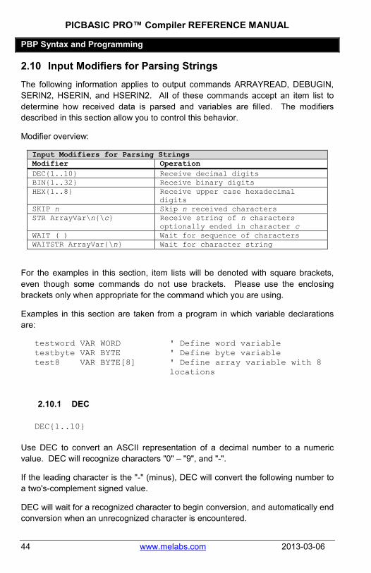
2.10 Input Modifiers for Parsing Strings The following information applies to output commands ARRAYREAD, DEBUGIN, SERIN2, HSERIN, and HSERIN2. All of these commands accept an item list to determine how received data is parsed and variables are filled. The modifiers described in this section allow you to control this behavior.
Modifier overview:
Input Modifiers for Parsing Strings Modifier Operation DEC{1..10} Receive decimal digits BIN{1..32} Receive binary digits HEX{1..8} Receive upper case hexadecimal
digits SKIP n Skip n received characters STR ArrayVar\n{\c} Receive string of n characters
optionally ended in character c WAIT ( ) Wait for sequence of characters WAITSTR ArrayVar{\n} Wait for character string
For the examples in this section, item lists will be denoted with square brackets, even though some commands do not use brackets. Please use the enclosing brackets only when appropriate for the command which you are using.
Examples in this section are taken from a program in which variable declarations are:
testword VAR WORD ' Define word variable testbyte VAR BYTE ' Define byte variable test8 VAR BYTE[8] ' Define array variable with 8
locations
2.10.1 DEC
DEC{1..10}
Use DEC to convert an ASCII representation of a decimal number to a numeric value. DEC will recognize characters "0" – "9", and "-".
If the leading character is the "-" (minus), DEC will convert the following number to a two's-complement signed value.
DEC will wait for a recognized character to begin conversion, and automatically end conversion when an unrecognized character is encountered.

PICBASIC PRO™ Compiler REFERENCE MANUAL
PBP Syntax and Programming
2013-03-06 www.melabs.com 45
When written with a number (DEC2, DEC10, etc.), DEC will end the conversion when the specified number of digits are collected.
input: "X-1011Y-546Z-F7ZZ-0001" [WAIT("Y"), DEC testword]
Waits for ASCII "Y", then looks for an ASCII string that could represent a decimal number. It finds the string "-546", which it converts to a signed integer and stores in testword.
input: "X-1011Y-547Z-F7ZZ-0001" [WAIT("Y-"),DEC2 testword, testbyte]
In this example, we use the DEC2 modifier to collect the only 2 decimal digits after the wait-string "Y-" is received. This results in the decimal value 54 being stored to testword. The next character is "7", which is stored as ASCII in testbyte. The testbyte value is decimal 55, which is the ASCII code for "7".
2.10.2 BIN
BIN{1..32}
Use BIN to convert an ASCII representation of a binary number to a numeric value. BIN will recognize characters "0", "1", and "-".
If the leading character is the "-" (minus), BIN will convert the following number to a two's-complement signed value.
BIN will wait for a recognized character to begin conversion, and automatically end conversion when an unrecognized character is encountered.
When written with a number (BIN2, BIN16, etc.), BIN will end the conversion when the specified number of digits are collected.
input: "X-1011Y-546Z-F7ZZ-0001" [WAIT("X"), BIN testbyte]
Waits for ASCII "X", then looks for an ASCII string that could represent a binary number. It finds the string "-1011", which it converts to a signed integer. Value in testbyte is %11110101, which is the two's-complement equivalent of %-1011.

PICBASIC PRO™ Compiler REFERENCE MANUAL
PBP Syntax and Programming
46 www.melabs.com 2013-03-06
input: "X-1011Y-546Z-F7ZZ-0001" [WAIT("ZZ-"), BIN testbyte]
Waits for ASCII string "ZZ-", then looks for a string that could represent a binary number. It finds "0001", which it converts to a signed integer. Value in testbyte is %00000001.
2.10.3 HEX
HEX{1..8}
Use HEX to convert an ASCII representation of a binary number to a numeric value. HEX will recognize characters "0"-"9", "a"-"f", "A"-"F", and "-"
If the leading character is the "-" (minus), HEX will convert the following number to a two's-complement signed value.
HEX will wait for a recognized character to begin conversion, and automatically end conversion when an unrecognized character is encountered.
When written with a number (HEX2, HEX4, etc.), HEX will end the conversion when the specified number of digits are collected.
input: "X-1011Y-546Z-F7ZZ-0001" [WAIT("X-"), HEX testbyte]
Waits for ASCII string "X-", then looks for a string that could represent a hexadecimal number. It finds "1011" which it tries to store in the testbyte variable. Since the value of $1011 is too large for a single byte, it only stores the least significant 8 bits. Value in testbyte is $11 or %00010001.
input: "X-1011Y-546Z-F7ZZ-0001" [WAIT("X-"), HEX2 testbyte]
Same as previous example, but we have used HEX2 instead of HEX. This causes the compiler to collect the string "10" and store it in testbyte. Value in testbyte is $10 or %00010000.

PICBASIC PRO™ Compiler REFERENCE MANUAL
PBP Syntax and Programming
2013-03-06 www.melabs.com 47
input: "X-1011Y-546Z-F7ZZ-0001" [WAIT("Z-"), HEX testbyte]
Since this example waits for the string "Z-", it ignores the "1011" string. The first string it finds that could be hex data is "F7". Value in testbyte is $F7.
2.10.4 SKIP
SKIP n
Use SKIP (followed by a count 255 or less) to skip the specified number of characters before resuming processing.
input: "X-1011Y-546Z-F7ZZ-0001" [WAIT("Y"), SKIP 2, DEC2 testword, testbyte]
Waits for the string "Y", then skips the next 2 characters "-5". It then collects the 2-digit decimal number 46 and stores it to testword. The next byte received is "Z", which is stored as ASCII to testbyte.
2.10.5 STR
STR ArrayVar\n{\c}
The STR modifier is used to move data into an array variable without converting it.
STR must be followed by a backslash and a number that specifies how many characters (bytes) to collect.
Optionally, an additional backslash can be added and followed by a character, cause STR to collect characters until it encounters the character you specify.

PICBASIC PRO™ Compiler REFERENCE MANUAL
PBP Syntax and Programming
48 www.melabs.com 2013-03-06
input: "X-1011Y-546Z-F7ZZ-0001" [WAIT("F"), STR test8\8]
Waits for the string "F", then collects the next 8 characters. These are stored as ASCII in 8 locations of the array variable test8. Values in test8 array are:
test8[0] = "7" test8[1] = "Z" test8[2] = "Z" test8[3] = "-" test8[4] = "0" test8[5] = "0" test8[6] = "0" test8[7] = "1"
input: "X-1011Y-546Z-F7ZZ-0001" [WAIT("Z-"), STR test8\8\"0"]
The STR item is similar to the previous example, but it demonstrates the use of the stop character "0". When it encounters "0" at the sixth character, it replaces it and fills the rest of the test8 array with null (zero) values. Values in test8 array are:
test8[0] = "F" test8[1] = "7" test8[2] = "Z" test8[3] = "z" test8[4] = "-" test8[5] = 0 test8[6] = 0 test8[7] = 0
2.10.6 WAIT
WAIT ( )
The WAIT() modifier is used to suspend processing until a match for a specific constant to string is encountered.

PICBASIC PRO™ Compiler REFERENCE MANUAL
PBP Syntax and Programming
2013-03-06 www.melabs.com 49
The data within the parentheses can be a comma-separated list of values, a string in quotes, or a combination of both.
input: "X-1011Y-546Z-F7ZZ-0001" [WAIT("X"), testbyte]
Waits for ASCII "X", then reads the next byte without a modifier. Numeric value of testbyte is 45, the ASCII code for "-".
input: "X-1011Y-546Z-F7ZZ-0001" [WAIT("Y-"), DEC testword, WAIT("-"), HEX testbyte]
Waits for the string "Y-", then collects a string that could represent a decimal number ("546"). It then waits again for the string "-". After that it collects the next string that looks like hex data, "F7".
input: "X-1011Y-546Z-F7ZZ-0001" [WAIT("Z",45), STR test8\8\"0"]
This example demonstrates how you can put multiple characters in the WAIT. It waits for the string "Z-", since the ASCII code for "-" is 45.
2.10.7 WAITSTR
WAITSTR ArrayVar{\n}
WAITSTR is used like WAIT, but it attempts to match against a string that has been previously stored in an array variable.
The following examples use the test8 array in the WAITSTR modifier. These examples use ARRAYWRITE to set the value in test8 before each test.
ARRAYWRITE test8, ["X-"] input: "X-1011Y-546Z-F7ZZ-0001" [WAITSTR test8\2, testbyte]
Waits for ASCII "X-", then reads the next byte without a modifier. testbyte = "1"

PICBASIC PRO™ Compiler REFERENCE MANUAL
PBP Syntax and Programming
50 www.melabs.com 2013-03-06
ARRAYWRITE test8, ["F7ZZ-"] input: "X-1011Y-546Z-F7ZZ-0001" [WAITSTR test8\5, testbyte]
Waits for ASCII "F7ZZ-", then reads the next byte without a modifier. testbyte = "0"

PICBASIC PRO™ Compiler REFERENCE MANUAL
PBP Syntax and Programming
2013-03-06 www.melabs.com 51
2.11 Output Modifiers for Formatting Strings The following information applies to output commands ARRAYWRITE, DEBUG, SEROUT2, HSEROUT, HSEROUT2, and LCDOUT. All of these commands accept an item list to determine output. Numeric data included in this item list can be converted to ASCII strings using the following modifiers.
Output Modifiers for Formatting Strings Modifier Operation {I}{S}DEC{1..10} Send decimal digits {I}{S}BIN{1..32} Send binary digits {I}{S}HEX{1..8} Send hexadecimal digits REP char\count Send character c repeated n
times STR ArrayVar{\count} Send string of n characters
For the examples in this section, item lists will be denoted with square brackets ( [ ] ), even though some commands do not use brackets. Please use the enclosing brackets only when appropriate for the command you are using.
2.11.1 DEC
{I}{S}DEC{1..10}
Use DEC to convert a numeric value to a string that represents the number in decimal format.
When preceded by the letter "I", DEC will format the output with a leading "#" character to signify decimal.
When preceded by the letter "S", DEC will interpret the input value as signed (two's-complement), and format the output with a minus sign "-" if negative. If the "S" is not used, DEC interprets all values (including signed LONGs) as positive integers.
When a number (1-10) is appended to the DEC modifier, the output is limited to the specified number of decimal digits. If the number of digits specified is more than required to represent the value, leading zeros will be used to pad the output string. If the number of digits specified is less than required to accurately represent the value, only the specified number of trailing digits will be displayed and the most significant (leading) digits will be truncated.

PICBASIC PRO™ Compiler REFERENCE MANUAL
PBP Syntax and Programming
52 www.melabs.com 2013-03-06
testword = 50123 [DEC testword] output: "50123" testword = 56 [DEC testword] output: "56"
The most common usage of DEC. Number of output digits changes with the value of the input.
testword = 50123 [DEC3 testword] output: "123" testword = 56 [DEC3 testword] output: "056"
DEC3 is used to force a 3-character output. Leftmost digits are truncated if necessary. Leading zeros are used to pad the output.
testword = 50123 [SDEC testword] output: "-15413" testword = 56 [SDEC testword] output: "56" testword = 56 [SDEC4 testword] output: "0056"
Since 50123 (stored in a 16-bit variable) is equivalent to the signed, two's-complement value -15413, SDEC will output the negative value with a minus sign.
If the sign bit isn't set in a variable, as is the case with value 56, SDEC gives the same result as DEC.

PICBASIC PRO™ Compiler REFERENCE MANUAL
PBP Syntax and Programming
2013-03-06 www.melabs.com 53
testword = 50123 [ISDEC testword] output: "#-15413" testword = 56 [IDEC testword] output: "#56"
IDEC and ISDEC prepend a "#" character before the output string.
testword = 50123 [DEC testword/1000, ".", DEC3 testword] output: "50.123"
DEC can be used to easily generate an output string with decimal places.
"DEC testword/1000" outputs the decimal representation of the testword value divided by one thousand ("50").
"DEC3 testword" outputs the least-significant three decimal digits ("123").
2.11.2 BIN
{I}{S}BIN{1..32}
Use BIN to convert a numeric value to a string that represents the number in binary format.
When preceded by the letter "I", BIN will format the output with a leading "%" character to signify binary.
When preceded by the letter "S", BIN will interpret the input value as signed (two's-complement), and format the output with a minus sign "-" if negative. If the "S" is not used, BIN interprets all values (including signed LONGs) as positive integers.
When a number (1-32) is appended to the BIN modifier, the output is limited to the specified number of binary digits. If the number of digits specified is more than required to represent the value, leading zeros will be used to pad the output string. If the number of digits specified is less than required to accurately represent the

PICBASIC PRO™ Compiler REFERENCE MANUAL
PBP Syntax and Programming
54 www.melabs.com 2013-03-06
value, only the specified number of trailing digits will be displayed and the most significant (leading) digits will be truncated.
testbyte = %11001011 [BIN testbyte] output: "11001011"
BIN creates an output string composed of characters "1" and "0" to represent the binary value.
testbyte = %11001011 [IBIN testbyte] output: "%11001011"
IBIN prepends a "%" character before the value to signify binary.
testbyte = %11001011 [SBIN testbyte] output: "-110101"
Since %11001011 can represent a negative number when stored in a byte variable, SDEC will output the string to show this.
testbyte = %11001011 [IBIN16 testbyte] output: "%0000000011001011"
IBIN16 forces the output to be 16 binary digits and prepends a "%" to signify binary
2.11.3 HEX
{I}{S}HEX{1..8}
Use HEX to convert a numeric value to a string that represents the number in hexadecimal format.
When preceded by the letter "I", HEX will format the output with a leading "$" character to signify hexadecimal.

PICBASIC PRO™ Compiler REFERENCE MANUAL
PBP Syntax and Programming
2013-03-06 www.melabs.com 55
When preceded by the letter "S", HEX will interpret the input value as signed (two's-complement), and format the output with a minus sign "-" if negative. If the "S" is not used, HEX interprets all values (including signed LONGs) as positive integers.
When a number (1-8) is appended to the HEX modifier, the output is limited to the specified number of hexadecimal digits. If the number of digits specified is more than required to represent the value, leading zeros will be used to pad the output string. If the number of digits specified is less than required to accurately represent the value, only the specified number of trailing digits will be displayed and the most significant (leading) digits will be truncated.
testword = $C3F0 [HEX testword] output: "C3F0"
HEX creates an output string that represents a hexadecimal number.
testword = $C3F0 [IHEX testword] output: "$C3F0"
IHEX prepends a "$" character to signify hexadecimal
testword = $C3F0 [SHEX testword] output: "-3C10"
SHEX interprets the 16-bit input value as a two's-complement signed number and outputs a string that represents the negative value.
testword = $C3F0 [HEX2 testword] output: "F0"
HEX2 limits the output string to two hexadecimal digits

PICBASIC PRO™ Compiler REFERENCE MANUAL
PBP Syntax and Programming
56 www.melabs.com 2013-03-06
2.11.4 REP
REP char\count
Use REP to repeat a character a specified number of times in the output string.
The character is limited to a single character. Multiple-character strings are not allowed.
The character count may be a constant or variable, maximum 255.
[REP "@"\16] output: "@@@@@@@@@@@@@@@@"
REP is used to repeat a single character multiple times.
testbyte = 16 [REP "@"\testbyte] output: "@@@@@@@@@@@@@@@@"
A variable may be used to store the character and/or the count. This can be useful for padding with a variable number of spaces.
2.11.5 STR
STR ArrayVar{\count}
STR followed by a byte array variable and optional count will send a string of characters.
The number of output characters may be specified by a count appended with a backslash. The count can be a constant or variable, maximum value 255.
Output begins at the zero location in the array and counts upward. If a null (zero) is encountered in the array, the output is terminated.
ARRAYWRITE testarray, ["Hello World",0] [STR testarray\5] output: "Hello"
Use STR to output the contents of an array variable. The \5 causes only the first 5 characters in the array to be output.

PICBASIC PRO™ Compiler REFERENCE MANUAL
PBP Syntax and Programming
2013-03-06 www.melabs.com 57
ARRAYWRITE testarray, ["Hello World",0] [STR testarray] output: "Hello World"
Use STR to output the contents of an array variable. Output terminates when the null (zero) value is encountered.

PICBASIC PRO™ Compiler REFERENCE MANUAL
PBP Syntax and Programming
58 www.melabs.com 2013-03-06
2.12 Numbers When you write numeric values in a program, PBP allows you to write them as base-10 decimal, base-16 hexadecimal, or base-2 binary.
To write a decimal number, simply write it without a prefix:
x = 255
To write a hexadecimal number, prefix it with "$" to let PBP know how to interpret it:
x = $FF
To write a binary number, prefix it with "%":
x = %11111111
There is no penalty associated with one number format over another. You may choose the format that makes the most sense to you. To PBP, a number is a number. These choices are simply different ways to represent the exact same value.
PBP will also accept a quoted ASCII character as a number. If you write a character in quotes, it will be converted to the numeric ASCII code that represents the character in the standard ASCII character set:
x = "A" ' same as writing x = 65

PICBASIC PRO™ Compiler REFERENCE MANUAL
PBP Syntax and Programming
2013-03-06 www.melabs.com 59
2.13 Registers The term "Register" refers to a special memory location that is built into the microcontroller. These locations are part of the construction of the chip, and they each perform a special function. In Microchip's documents, you will see them referred to as "Special Function Registers" or "SFRs".
In PBP programs, registers may be accessed by name, without any special pre-definition. We call this Direct Register Access. When you read a PBP example program, you may see something like:
ANSEL = 0 ' Make all pins digital
This can be confusing to the novice, because "ANSEL" isn't declared as a variable and it isn't a command. It is the name of a register on a specific PIC microcontroller. Note that the register names aren't the same for all PIC devices, nor do similarly-named registers work the same from one device to the next.
The details about the registers are found in the Microchip datasheet for the device you are compiling for. The datasheet is your friend. We don't advocate reading it from cover to cover in one sitting, but you need to be comfortable with it as a reference document. It holds the keys to exploiting the power of the microcontroller.

PICBASIC PRO™ Compiler REFERENCE MANUAL
PBP Syntax and Programming
60 www.melabs.com 2013-03-06
2.14 Comments Comments in PBP are denoted with an apostrophe ( ' ) or a semicolon ( ; ).
Comments don't consume any resources. Most programmers will agree that you will never save time by omitting a comment. A well written program devotes more space to comments than to code. Our recommendation is to shrink your code, expand your comments.
There is no penalty for long, informative comments:
' using IOCBF you can tap 1 or more keys very fast, and ' never miss a press. Much faster than reading the ' entire port. And key presses do not generate an ' interrupt. Only set flag bits in IOCBF for each ' individual input that was edge-triggered. IF IocFlag THEN ' if keys SW13, 14, 15 or 16 were ' pressed, State = 1 ' indicate LCD update needed GOSUB GetKeys ' get the button/buttons pressed ENDIF

PICBASIC PRO™ Compiler REFERENCE MANUAL
PBP Syntax and Programming
2013-03-06 www.melabs.com 61
2.15 Case Sensitivity PBP is not case sensitive, but Assembly Language is. This means that there are situations where case matters.
2.15.1 DEFINEs
Since many of the DEFINEs in PBP pass data directly to the assembler, they should be considered case-sensitive. All defined parameters should be written in upper-case:
DEFINE OSC 20 ' Correct DEFINE osc 20 ' Incorrect, and will not
generate an error message
2.15.2 Variables
PBP doesn't differentiate different case-versions of variable names. To PBP, "speed" is the same as "Speed".
Sometimes, though, a variable name will be written in an Assembly Language routine that is included in the PBP program using commands @ or ASM..ENDASM. In the Assembly Language code, variable names do become case-sensitive.
Speed VAR BYTE SYSTEM speed = 0 'Allowed in PBP @ clrf speed 'may cause error @ clrf Speed 'Correct

PICBASIC PRO™ Compiler REFERENCE MANUAL
PBP Syntax and Programming
62 www.melabs.com 2013-03-06
2.16 White Space White Space refers to spaces and tabs inserted in commands. Inserting white space thoughtfully can make a program easier to read and understand. Some PBP commands need white space to separate things. PBP doesn't care if tabs are used instead of spaces, nor does it care if multiple white space characters are used instead of a single character.
LCDOUT DEC speed 'Single spaces used LCDOUT DEC speed 'Tabs or multiple spaces used
Assembly Language is sensitive to starting column, and starting column is controlled by adding white space. The correct Assembly Language syntax is beyond the scope of this manual, but here is an example of the most common error:
@clrf Speed ;Command clrf in first column causes error
@ clrf Speed ;Correct with tab or spaces

PICBASIC PRO™ Compiler REFERENCE MANUAL
PBP Syntax and Programming
2013-03-06 www.melabs.com 63
2.16.1 Tabbing For Readability
It is customary to indent program lines using tabs to help show the intended structure of a program. Blocks of code that operate conditionally, or in a loop, are indented to make the conditional or loop structure easier to see. Nested blocks and loops are given an additional level of indentation. Consider the following example for readability.
FOR x = 0 TO 8 PORTA = x IF x = 2 THEN PORTB = PORTB + 1 ELSE PORTB = PORTC ENDIF NEXT x
Without indented lines, the program is much more difficult to decipher:
FOR x = 0 TO 8 PORTA = x IF x = 2 THEN PORTB = PORTB + 1 ELSE PORTB = PORTC ENDIF NEXT x

PICBASIC PRO™ Compiler REFERENCE MANUAL
PBP Syntax and Programming
64 www.melabs.com 2013-03-06
2.17 Line-Extension ( _ ) Long lines of program code in PBP can be broken into multiple lines for readability. This is accomplished using an underscore ( _ ) to tell PBP to continue parsing the current command on the next line. The underscore must be the last character on the line that you break.
This is very useful for long lookup tables and item lists:
LOOKUP I, [$45,$35,$67,$7E,_ $8F,$00,$0F,$C0,_ $EF,$55,$01,$00], value

PICBASIC PRO™ Compiler REFERENCE MANUAL
PBP Syntax and Programming
2013-03-06 www.melabs.com 65
2.18 Line-Concatenation ( : ) Multiple commands may be written on a single line using colon characters to tell PBP where to insert a "virtual" line break. This can pack more code into less space, but it generally makes the program more difficult to read.
x = x + 2 : HIGH led : LOW cs

PICBASIC PRO™ Compiler REFERENCE MANUAL
PBP Syntax and Programming
66 www.melabs.com 2013-03-06
2.19 INCLUDE Use PBP's INCLUDE directive to read a text file and place its contents in your program. INCLUDE performs a simple text substitution at the location where INCLUDE is written.
INCLUDE "more_code.pbp" 'include file contents here

PICBASIC PRO™ Compiler REFERENCE MANUAL
Operators
2013-03-06 www.melabs.com 67
Chapter 3: Operators

PICBASIC PRO™ Compiler REFERENCE MANUAL
Operators
68 www.melabs.com 2013-03-06
Overview of Operators
Math Operators Description
+ Addition - Subtraction * Multiplication ** Top 16 Bits of
Multiplication */ Middle 16 Bits of
Multiplication / Division // Remainder (Modulus) << Shift Left >> Shift Right ABS Absolute Value* ATN Arctangent COS Cosine DCD 2n Decode DIG Digit DIV32 31-bit x 15-bit Divide HYP Hypotenuse MAX Maximum* MIN Minimum* NCD Encode REV Reverse Bits SIN Sine SQR Square Root
Bitwise Operators Description & Bitwise AND | Bitwise OR ^ Bitwise Exclusive OR ~ Bitwise NOT &/ Bitwise NOT AND |/ Bitwise NOT OR ^/ Bitwise NOT Exclusive OR << SHIFT LEFT >> SHIFT RIGHT

PICBASIC PRO™ Compiler REFERENCE MANUAL
Operators
2013-03-06 www.melabs.com 69
Comparison Operator Description
= or == Equal to <> or != Not Equal to < Less Than to > Greater Than to <= Less Than or Equal to >= Greater Than or Equal to
Logical Operator Description
AND or && Logical AND OR or || Logical OR XOR or ^^ Logical Exclusive OR
NOT or ! Logical NOT ANDNOT Logical NAND ORNOT Logical NOR XORNOT Logical NXOR

PICBASIC PRO™ Compiler REFERENCE MANUAL
Operators
70 www.melabs.com 2013-03-06
PICBASIC PRO Compiler performs all operations in full hierarchal order. This means that there is precedence to the operators. Multiplies and divides are performed before adds and subtracts. If incorrect assumptions are made about the order in which operations are performed, you may encounter unexpected results. To ensure the operations are carried out in the order that you intended, use parenthesis to group the operations. Parenthesis may be used to group all types of operators, including mathematical, comparison, bitwise, and logical.
A = (B + C) * (D - E)
IF (((PORTA >> 4) < 6) OR (PORTB = 0)) THEN…
The following table lists the operators in default hierarchal order. (Parentheses will override.) Operators with the same precedence level (on the same line in the table below) will be evaluated in the order (left to right) that they are encountered in the written expression.
Highest Precedence
( ) (anything enclosed in parentheses) - (unary) ! or NOT, ABS, COS, DCD, DIV32, NCD, SIN, SQR <<, >>, ATN, DIG, HYP, MAX, MIN, REV *, /, **, */, // +, - (in math), ~ = or ==, <> or !=, <, <=, >, >= &, |, ^, &/, |/, ^/ AND, OR, XOR, ANDNOT, ORNOT, XORNOT
Lowest Precedence Left-to-right is, in our opinion, unacceptable as a method of specifying the order of evaluation. USE PARENTHESES to avoid ambiguity!
All math operations when compiling with PBPW are unsigned and performed with 16-bit precision. Math operations for PBPL use 32-bit precision and may be signed or unsigned, depending on the variable-types used.
Bitwise operators, including the shift operators, always operate in an unsigned fashion, regardless of the variable type they are acting on, signed or unsigned.

PICBASIC PRO™ Compiler REFERENCE MANUAL
Mathematical Operators
2013-03-06 www.melabs.com 71
3.1 Math Operators Math Operators Description
+ Addition - Subtraction * Multiplication ** Top 16 Bits of
Multiplication */ Middle 16 Bits of
Multiplication / Division // Remainder (Modulus) << Shift Left >> Shift Right ABS Absolute Value* ATN Arctangent COS Cosine DCD 2n Decode DIG Digit DIV32 31-bit x 15-bit Divide HYP Hypotenuse MAX Maximum* MIN Minimum* NCD Encode REV Reverse Bits SIN Sine SQR Square Root
3.1.1 Multiplication
PBPW performs unsigned 16-bit x 16-bit multiplication, while PBPL performs signed 32-bit x 32-bit multiplication.
W1 = W0 * 1000 ' Multiply value in W0 by 1000 and place the result in W1
PBPL interprets only LONG variable types as signed numbers. Words, bytes, and of course bits are always interpreted as positive, unsigned integers when used as inputs in a PBP math operation.
If the result of a multiplication could possibly be negative, it should be stored to a LONG variable type to preserve the sign. If a negative result is placed in a variable type other than LONG, subsequent calculations using this value will interpret it as a positive number.

PICBASIC PRO™ Compiler REFERENCE MANUAL
Mathematical Operators
72 www.melabs.com 2013-03-06
B0 = 4 L0 = B0 * -1 ' Result is -4 in L0 W0 = B0 * -1 ' Result is 65532 in W0
3.1.2 '*/' and '**' Special Multiplication
There are two special multiplication operators that allow large result values to be handled in a special way. These operators ignore some of the least-significant bytes of the result and return higher order bytes instead. With PBPW, this allows you to work (in a limited way) with 32-bit multiplication results. With PBPL, the top 32 bits of a 48-bit result are available.
The '*/' operator discards the least-significant byte of the result (byte0), and returns the 4 higher bytes to the result variable. If the result variable is a word or byte, the value will be truncated to fit.
W3 = W1 */ W0 ' Multiply W1 by W0, ignorebyte0 of the result, return byte1 and byte2 in W3
L3 = L1 */ L0 ' Multiply L1 by L0, ignore byte0 of the result, return byte1 through byte4 in L3
A simple way to think about '*/' is that it shifts the result 8 places to the right, resulting in an automatic division by 256. (This does not hold true if the result is a negative number.) This is useful for multiplying by non-integer constants.
If you wished to convert miles to kilometers, for example, you would need to multiply by a constant 1.6. PBP's integer math won't allow you to write "1.6" in an equation, but you can use '*/' to accomplish the same result:
kilometers = miles */ 410 ' Same as kilometers = (miles * 410) / 256
The '**' operator is similar, but ignores two bytes instead of one. When using PBPL with long variable types, it returns byte2 through byte5 of the 48-bit result value. This gives a result that is shifted 16 places to the right, an inherent divide by 65536.
W2 = W0 ** 1000 ‘ Multiply W0 by 1000 and place the high order 16 bits (which may be 0) in W2
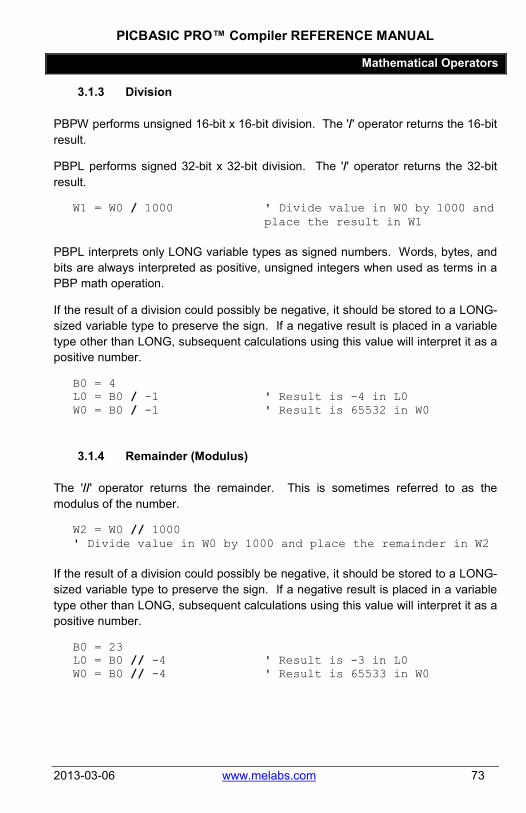
PICBASIC PRO™ Compiler REFERENCE MANUAL
Mathematical Operators
2013-03-06 www.melabs.com 73
3.1.3 Division
PBPW performs unsigned 16-bit x 16-bit division. The '/' operator returns the 16-bit result.
PBPL performs signed 32-bit x 32-bit division. The '/' operator returns the 32-bit result.
W1 = W0 / 1000 ' Divide value in W0 by 1000 and place the result in W1
PBPL interprets only LONG variable types as signed numbers. Words, bytes, and bits are always interpreted as positive, unsigned integers when used as terms in a PBP math operation.
If the result of a division could possibly be negative, it should be stored to a LONG-sized variable type to preserve the sign. If a negative result is placed in a variable type other than LONG, subsequent calculations using this value will interpret it as a positive number.
B0 = 4 L0 = B0 / -1 ' Result is -4 in L0 W0 = B0 / -1 ' Result is 65532 in W0
3.1.4 Remainder (Modulus)
The '//' operator returns the remainder. This is sometimes referred to as the modulus of the number.
W2 = W0 // 1000 ' Divide value in W0 by 1000 and place the remainder in W2
If the result of a division could possibly be negative, it should be stored to a LONG-sized variable type to preserve the sign. If a negative result is placed in a variable type other than LONG, subsequent calculations using this value will interpret it as a positive number.
B0 = 23 L0 = B0 // -4 ' Result is -3 in L0 W0 = B0 // -4 ' Result is 65533 in W0

PICBASIC PRO™ Compiler REFERENCE MANUAL
Mathematical Operators
74 www.melabs.com 2013-03-06
3.1.5 ABS
ABS returns the absolute value of a number. If a byte is greater than 127 (high bit set), ABS will return 256 - value. If a word is greater than 32767 (high bit set), ABS will return 65536 - value. If a long is negative, ABS will return 4294967296 - value.
B1 = ABS B0
ABS always interprets input variables and expressions as two's-complement signed numbers. This is true regardless of PBPW/PBPL mode selection and/or variable type.
3.1.6 ATN
ATN returns the 8-bit arctangent of 2 two's-complement 8-bit values. If a byte is greater than 127 (high bit set), it is treated as a negative value. The arctangent returned is in binary radians, 0 to 255, representing a range of 0 to 359 degrees.
ang = x ATN y
3.1.7 COS
COS returns the 8-bit cosine of a value. The result is in two’s complement form (i.e. -127 to 127). It uses a quarter-wave lookup table to find the result. Cosine starts with a value in binary radians, 0 to 255, as opposed to the usual 0 to 359 degrees.
B1 = COS B0
3.1.8 DCD
DCD returns the decoded value of a bit number. It changes a bit number (0 - 31) into a binary number with only that bit set to 1. All other bits are set to 0.
B0 = DCD 2 ' Sets B0 to %00000100
3.1.9 DIG
DIG returns the value of a decimal digit. Input the digit number (0 – 9, with 0 being the rightmost digit). DIG returns the value of the decimal digit that you specified.

PICBASIC PRO™ Compiler REFERENCE MANUAL
Mathematical Operators
2013-03-06 www.melabs.com 75
DIG is commonly used to distill BCD digits from numeric values and to isolate single digits for display on seven-segment LCD.
B0 = 123 ' Set B0 to 123 B1 = B0 DIG 2 ' Sets B1 to 1 (digit 2 of 123)
3.1.10 DIV32
PBPW’s multiply (*) function operates as a 16-bit x 16-bit multiply yielding a 32-bit internal result. However, since PBPW only supports a maximum variable size of 16 bits, access to the result had to happen in 2 steps: c = b * a returns the lower 16 bits of the multiply while d = b ** a returns the upper 16 bits. There was no way to access the 32-bit result as a unit.
In many cases it is desirable to be able to divide the entire 32-bit result of the multiply by a 16-bit number for averaging or scaling. A special operator has been provided for this purpose: DIV32. DIV32 is actually limited to dividing a 31-bit unsigned integer (max 2147483647) by a 15-bit unsigned integer (max 32767). This should suffice in most circumstances.
As PBPW only allows a maximum variable size of 16 bits, DIV32 assumes that a multiply was just performed and that the internal compiler variables still contain the 32-bit result of the multiply. No other operation may occur between the multiply and the DIV32, else the internal variables may be altered, destroying the 32-bit multiplication result.
This means, among other things, that ON INTERRUPT must be DISABLEd from before the multiply until after the DIV32. If ON INTERRUPT is not used, there is no need to add DISABLE to the program. Interrupts in assembler should have no effect on the internal variables so they may be used without regard to DIV32.
The following code fragment shows the operation of DIV32:

PICBASIC PRO™ Compiler REFERENCE MANUAL
Mathematical Operators
76 www.melabs.com 2013-03-06
a VAR WORD b VAR WORD c VAR WORD dummy VAR WORD b = 500 c = 1000 DISABLE ' Necessary if On Interrupt used dummy = b * c ' Could also use ** or */ a = DIV32 100 ENABLE ' Necessary if On Interrupt used
This program assigns b the value 500 and c the value 1000. When multiplied together, the result would be 500000. This number exceeds the 16-bit word size of a variable (65535). So the dummy variable contains only the lower 16 bits of the result. In any case, it is not used by the DIV32 function. DIV32 uses variables internal to the compiler as the operands.
In this example, DIV32 divides the 32-bit result of the multiplication b * c by 100 and stores the result of this division, 5000, in the word-sized variable a.
DIV32 is not supported by PBPL as that version of the compiler always uses a 32-bit x 32-bit divide.
3.1.11 HYP
HYP returns the hypotenuse of a right triangle, or the length of the side opposite the right angle. It simply calculates the square root of the sum of the squares of the length of the 2 sides adjacent to the right angle.
For PBPW, the input values are treated as two's-complement numbers representing a range of +127 to -128. For PBPL, a long variable or constant must be used if a negative value is to be represented. In any case, the value returned is always positive.
B2 = B0 HYP B1 ' Same as B2 = SQR ((B0 * B0)+ (B1 * B1))
3.1.12 MAX and MIN
MAX and MIN return the maximum and minimum, respectively, of two numbers. It is usually used to limit numbers to a value.

PICBASIC PRO™ Compiler REFERENCE MANUAL
Mathematical Operators
2013-03-06 www.melabs.com 77
B1 = B0 MAX 100 ' Set B1 to the larger of B0 and 100
B1 = B0 MIN 100 ' Set B1 to the smaller of B0 and 100
W0 = B0 MAX B1 ' Set W0 to the larger of B0 and B1
W0 = W1 MAX (B1 * B0) ' Set W0 to the larger of W1 and the result of expression (B1*B0)
3.1.13 NCD
NCD returns the priority encoded bit number (1 - 32) of a value. It is used to find the highest bit set in a value. It returns 0 if no bit is set.
B0 = NCD %01001000 ' Sets B0 to 7
3.1.14 REV
REV reverses the order of the lowest bits in a value. The number of bits to be reversed is from 1 to 32.
B0 = %10101100 REV 4 ' Sets B0 to %00000011
The result includes only the reversed bits. The bits that are not reversed are set to zeroes in the result.
3.1.15 SIN
SIN returns the 8-bit sine of a value. The result is in two’s complement form (i.e. -127 to 127). It uses a quarter-wave lookup table to find the result. SIN starts with a value in binary radians, 0 to 255, as opposed to the usual 0 to 359 degrees.
B1 = SIN B0
3.1.16 SQR
SQR returns the square root of a value as an 8-bit integer (16-bit for PBPL).
B0 = SQR W1 ' Sets B0 to square root of W1

PICBASIC PRO™ Compiler REFERENCE MANUAL
Bitwise Operators
78 www.melabs.com 2013-03-06
3.2 Bitwise Operators Bitwise Operators Description & Bitwise AND | Bitwise OR ^ Bitwise Exclusive OR ~ Bitwise NOT &/ Bitwise NOT AND |/ Bitwise NOT OR ^/ Bitwise NOT Exclusive OR << SHIFT LEFT >> SHIFT RIGHT
Bitwise operators perform manipulation of binary values. Since all numbers can be expressed as binary, bitwise operators can be performed on all values in PBP, including variables, constants, and internal registers.
With the exception of the SHIFT and Bitwise NOT operators, a bitwise operator applies its bitwise (Boolean) logic to each corresponding bit of two input values. The result may be placed in a variable or used in a comparison. Consider the following AND operation between two BYTE values:
%10101010 & %11110000 %10100000
Each of the 8 bit-positions is individually combined for a single bit result:
↓ ↓ ↓ ↓ ↓ ↓ ↓ ↓ %1 %0 %1 %0 %1 %0 %1 %0 & %1 %1 %1 %1 %0 %0 %0 %0 %1 %0 %1 %0 %0 %0 %0 %0
If the destination variable type has more bits than either input term, the result will be right-justified and undetermined bits will be zeros. For example:
A VAR BYTE B VAR BYTE C VAR WORD A = %10101010 B = %11110000 C = A & B ' C = %0000000010100000
The result of the AND operation of the two byte inputs is %10100000, but since the C variable is a 16-bit WORD the result in C will be %0000000010100000.
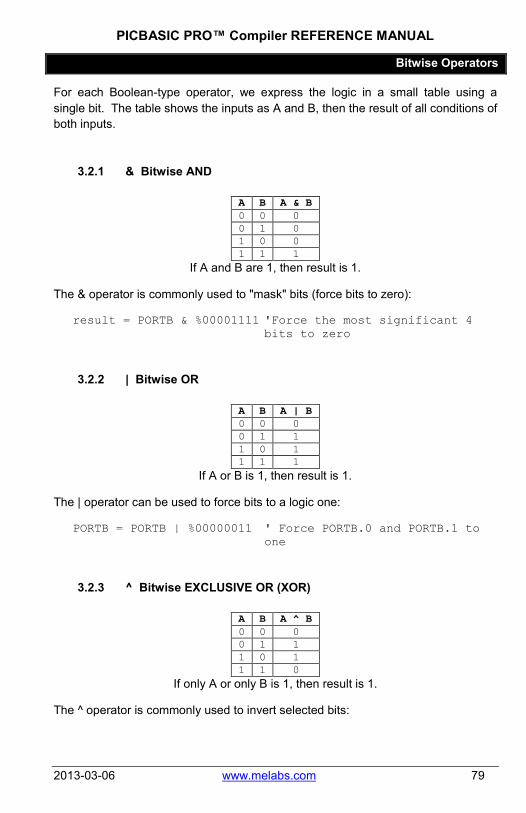
PICBASIC PRO™ Compiler REFERENCE MANUAL
Bitwise Operators
2013-03-06 www.melabs.com 79
For each Boolean-type operator, we express the logic in a small table using a single bit. The table shows the inputs as A and B, then the result of all conditions of both inputs.
3.2.1 & Bitwise AND
A B A & B 0 0 0 0 1 0 1 0 0 1 1 1
If A and B are 1, then result is 1.
The & operator is commonly used to "mask" bits (force bits to zero):
result = PORTB & %00001111 'Force the most significant 4 bits to zero
3.2.2 | Bitwise OR
A B A | B 0 0 0 0 1 1 1 0 1 1 1 1
If A or B is 1, then result is 1.
The | operator can be used to force bits to a logic one:
PORTB = PORTB | %00000011 ' Force PORTB.0 and PORTB.1 to one
3.2.3 ^ Bitwise EXCLUSIVE OR (XOR)
A B A ^ B 0 0 0 0 1 1 1 0 1 1 1 0
If only A or only B is 1, then result is 1.
The ^ operator is commonly used to invert selected bits:

PICBASIC PRO™ Compiler REFERENCE MANUAL
Bitwise Operators
80 www.melabs.com 2013-03-06
PORTB = PORTB ^ %00001111 'Invert only bits 3,2,1,0 of PORTB
3.2.4 ~ Bitwise NOT (INVERT)
A ~A 0 1 1 0
Result is the inverse of A.
The ~ operator works with a single input expression. The input is the expression immediately following the operator.
PORTB = ~ PORTB ' Invert every bit in PORTB result = ~ (PORTB & %00001111) 'Invert the result of the & operation
3.2.5 &/ Bitwise NOT AND (NAND)
A B A &/ B 0 0 1 0 1 1 1 0 1 1 1 0
Result is the inverse of bitwise AND.
The &/ operator returns the same result as the combination of ~ and &:
result = PORTB &/ %00001111 result = ~(PORTB & %00001111) ' Same result

PICBASIC PRO™ Compiler REFERENCE MANUAL
Bitwise Operators
2013-03-06 www.melabs.com 81
3.2.6 |/ Bitwise NOT OR (NOR)
A B A |/ B 0 0 1 0 1 0 1 0 0 1 1 0
Result is the inverse of bitwise OR.
The &/ operator returns the same result as the combination of ~ and !:
result = PORTB |/ %00001111 result = ~ (PORTB | %00001111) ' Same result
3.2.7 ^/ Bitwise NOT EXCLUSIVE OR (XNOR)
A B A ^/ B 0 0 1 0 1 0 1 0 0 1 1 1
Result is the inverse of bitwise XOR.
The ^/ operator returns the same result as the combination of ~ and ^:
result = PORTB ^/ %00001111 result = ~(PORTB ^ %00001111) ' Same result

PICBASIC PRO™ Compiler REFERENCE MANUAL
Bitwise Operators
82 www.melabs.com 2013-03-06
3.2.8 << SHIFT LEFT
The << operator shifts all the bits in the input to the left the specified number of places. The bits shifted "out" on the left are discarded. New bits shifted in are always zeros. Consider the following example that represents a SHIFT LEFT one place: (%10110111 << 1)
(discard) ← 1 ← 0 ← 1 ← 1 ← 0 ← 1 ← 1 ← 1 ← (zero) 0 1 1 0 1 1 1 0
Example:
A = $10110111 result = A << 1 ' result = %01101110 result = A << 2 ' result = %11011100 result = A << 3 ' result = %10111000
SHIFT LEFT is commonly used to multiply a value by a power of 2. Shifting executes a lot faster than multiplication, but is limited to powers of 2 (2, 4, 8, etc.) because of the operation can only be performed on binary numbers.
result = value << 2 ' SHIFT LEFT 2 places, same as (result = value * 4)
Another example is to move bit values in a variable out of the way so new bit values may be "shifted in" from the right:
FOR i = 0 TO 7 value = value << 1 'Shift bits left one place value.0 = PORTB.0 'read and store input
NEXT i

PICBASIC PRO™ Compiler REFERENCE MANUAL
Bitwise Operators
2013-03-06 www.melabs.com 83
3.2.9 >> SHIFT RIGHT
SHIFT RIGHT is identical to SHIFT LEFT, except the bits are moved to the right, the rightmost (least significant) bits are discarded, and zeros are used to fill the leftmost (most significant) bits.
SHIFT RIGHT is commonly used to divide a value by a power of 2. Shifting executes a lot faster than division, but is limited to powers of 2 (2, 4, 8, etc.) because of the operation can only be performed on binary numbers.
result = value >> 2 ' SHIFT LEFT 2 places, same as (result = value / 4)
Another common application is to move the most-significant 4 bits to the least significant position in the variable:
result = PORTB >> 4 'Read most-significant half of PORTB

PICBASIC PRO™ Compiler REFERENCE MANUAL
Comparison Operators
84 www.melabs.com 2013-03-06
3.3 Comparison Operators Comparison Operator Description
= or == Equal to <> or != Not Equal to < Less Than to > Greater Than to <= Less Than or Equal to >= Greater Than or Equal to
Comparison operators are used to compare (test the relationship of) two expressions. The concept is that the operator returns a true value (1) when the condition is satisfied and a false (0) if the condition is not satisfied. These operators are used in commands that perform tests in order to direct the program flow. Some common examples would be:
' Test for a switch input IF ( PORTB.0 = 0 ) THEN switched ' Loop until a counter expires DO WHILE ( counter > 0 ) LOOP
3.3.1 Signed vs. Unsigned Comparisons
Numbers in PBP may be treated as unsigned (always positive) or signed (positive and negative), depending on the type of variable in use. LONG variables are treated as signed, other variable types are not.
Bval VAR BYTE Lval VAR LONG Bval = -1 ' result is hex $FF Lval = -1 ' result is hex $FFFFFFFF
In the above example, PBP will treat the value in Bval as 255, but it will treat the value in Lval as -1. If you look for a negative value in Bval, you will never find it.
If ( Bval < 0 ) THEN negative 'Will never test true
Consideration should also be given to the typecasting of temp variables that PBP uses when a compound comparison is written. Consider the example:

PICBASIC PRO™ Compiler REFERENCE MANUAL
Comparison Operators
2013-03-06 www.melabs.com 85
Bval VAR BYTE Bval = 0 IF ((Bval – 1) < 0) THEN negative
In the above example, the expression "Bval – 1" will be written to a temp variable for holding before the comparison is executed. When using PBPW, the temp variable will be a WORD. When using PBPL, the temp variable will be a LONG. The result is that the comparison will return false in PBPW, but true in PBPL.
As with all operators in PBP, comparisons should be grouped with parenthesis to specify the order in which the comparisons are performed (see Logical Operators).
3.3.2 Equal To ( = or == )
expression1 = expression2
If the evaluated numeric result of expression1 is equal to that of expression2, the result is true. Otherwise, the result is false.
3.3.3 Not Equal To ( <> or != )
expression1 <> expression2
If the evaluated numeric result of expression1 is not equal to that of expression2, the result is true. Otherwise, the result is false.
3.3.4 Less Than ( < )
expression1 < expression2
If the evaluated numeric result of expression1 is less than that of expression2, the result is true. Otherwise, the result is false.
3.3.5 Greater Than ( > )
expression1 > expression2
If the evaluated numeric result of expression1 is greater than that of expression2, the result is true. Otherwise, the result is false.

PICBASIC PRO™ Compiler REFERENCE MANUAL
Comparison Operators
86 www.melabs.com 2013-03-06
3.3.6 Less Than or Equal To ( <= )
expression1 <= expression2
If the evaluated numeric result of expression1 is less than, or equal to, that of expression2, the result is true. Otherwise, the result is false.
3.3.7 Greater Than or Equal To ( => )
expression1 => expression2
If the evaluated numeric result of expression1 is greater than, or equal to, that of expression2, the result is true. Otherwise, the result is false.

PICBASIC PRO™ Compiler REFERENCE MANUAL
Logical Operators
2013-03-06 www.melabs.com 87
3.4 Logical Operators Logical Operator Description
AND or && Logical AND OR or || Logical OR XOR or ^^ Logical Exclusive OR
NOT or ! Logical NOT ANDNOT Logical NAND ORNOT Logical NOR XORNOT Logical NXOR
Logical operators are used to logically combine multiple comparisons. In other words, they allow you to test for multiple conditions within a single command. This is best shown by example:
IF (x = 0) AND ((y = 0) OR (z = 0)) THEN label
The above example will jump to the label if either y or z are equal to zero, provided that x is also equal to zero.
3.4.1 Using Parentheses
Note the way parentheses are used in the preceding example to specify the grouping of the logic. It's important to realize that, without parentheses, the logic can be interpreted differently:
IF x = 0 AND y = 0 OR z = 0 THEN label
The most likely result here will be that PBP interprets the conditional statement from left to right and groups it like this:
IF ((x = 0) AND (y = 0)) OR (z = 0) THEN label
The operation of the example has now changed dramatically. It will now jump to label if z is equal to zero, regardless of the state of x and y. USE PARENTHESES to avoid this confusion.
3.4.2 Logical vs. Bitwise
Logical operators are very different than bitwise operators! There are circumstances under which PBP will allow the use of logical operators in
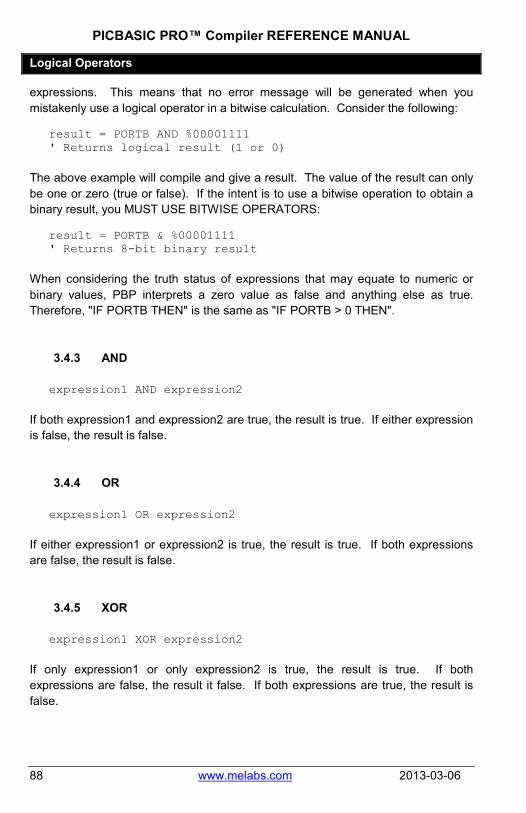
PICBASIC PRO™ Compiler REFERENCE MANUAL
Logical Operators
88 www.melabs.com 2013-03-06
expressions. This means that no error message will be generated when you mistakenly use a logical operator in a bitwise calculation. Consider the following:
result = PORTB AND %00001111 ' Returns logical result (1 or 0)
The above example will compile and give a result. The value of the result can only be one or zero (true or false). If the intent is to use a bitwise operation to obtain a binary result, you MUST USE BITWISE OPERATORS:
result = PORTB & %00001111 ' Returns 8-bit binary result
When considering the truth status of expressions that may equate to numeric or binary values, PBP interprets a zero value as false and anything else as true. Therefore, "IF PORTB THEN" is the same as "IF PORTB > 0 THEN".
3.4.3 AND
expression1 AND expression2
If both expression1 and expression2 are true, the result is true. If either expression is false, the result is false.
3.4.4 OR
expression1 OR expression2
If either expression1 or expression2 is true, the result is true. If both expressions are false, the result is false.
3.4.5 XOR
expression1 XOR expression2
If only expression1 or only expression2 is true, the result is true. If both expressions are false, the result it false. If both expressions are true, the result is false.

PICBASIC PRO™ Compiler REFERENCE MANUAL
Logical Operators
2013-03-06 www.melabs.com 89
3.4.6 NOT
NOT expression
If expression is true, result is false. If expression is false, result is true.
3.4.7 ANDNOT
expression1 ANDNOT expression2
If both expression1 and expression2 are false, the result is true. If either expression1 or expression2 is true, the result is false. Logically the same as:
NOT (expression1 AND expression2)
3.4.8 ORNOT
expression1 ORNOT expression2
If either expression1 or expression2 is true, the result is false. If both expression1 and expression2 are false, the result is true. Logically the same as:
NOT (expression1 OR expression2)
3.4.9 XORNOT
expression1 XORNOT expression2
If only expression1 or only expression2 is true, the result is false. If both expressions are false, the result is true. If both expressions are true, the result is true. Logically the same as:
NOT (expression1 XOR expression2)

PICBASIC PRO™ Compiler REFERENCE MANUAL
Directives
90 www.melabs.com 2013-03-06
Chapter 4: Directives
PICBASIC PRO™ Compiler REFERENCE MANUAL
Directives
2013-03-06 www.melabs.com 91
Directives are different than commands in that they only affect how the program is compiled. They don't actually execute when the program runs on the microcontroller. However, they may cause the compiler to insert code that does execute at run-time.
There are two types of directives in this section:
Preprocessor directives, denoted with a # character, were put in place to fill the need for users to conditionally compile sections of code and to access areas like device configuration which requires code-replacement at the lowest level.
Compile-Time directives advise the compiler to insert code for event handling, most notably interrupt handling. Directives like ON INTERRUPT specify a label for the handling routines. All compile-time directives also serve as markers, or boundaries, to denote sections in your program where event-handling code is inserted or omitted.
Note that compile-time directives are not dependent on program flow. They act "geographically" in your program, causing PBP to change compile methods for lines that fall below the directive. When you write "ENABLE", think "Enable for all lines below this point".
In interrupt code examples, you may see something like:
GOTO mainloop DISABLE myint: ' Interrupt handler routine
Many users question this, pointing out that the DISABLE will never execute. They are correct, it will never execute, but it doesn't matter. DISABLE is a marker that tells PBP to omit interrupt-checking background code for all program lines that are placed below the directive line. A correctly-commented example would read:
GOTO mainloop DISABLE ' Disable interrupt-checking for
all routines that follow. myint: ' Interrupt handler routine

PICBASIC PRO™ Compiler REFERENCE MANUAL
DISABLE
92 www.melabs.com 2013-03-06
4.1 DISABLE DISABLE
DISABLE both debug and interrupt processing following this instruction. Interrupts can still occur but the BASIC interrupt handler in the PICBASIC PRO program and the debug monitor will not be executed until an ENABLE is encountered.
DISABLE and ENABLE are pseudo-ops in that they give the compiler directions, rather than actually generate code. See ON DEBUG and ON INTERRUPT for more information.
DISABLE ' Disable interrupts in handler myint: led = 1 ' Turn on LED when interrupted Resume ' Return to main program Enable ' Enable interrupts after
handler

PICBASIC PRO™ Compiler REFERENCE MANUAL
DISABLE DEBUG
2013-03-06 www.melabs.com 93
4.2 DISABLE DEBUG DISABLE DEBUG
DISABLE DEBUG processing following this instruction. The debug monitor will not be called between instructions until an ENABLE or ENABLE DEBUG is encountered.
DISABLE DEBUG and ENABLE DEBUG are pseudo-ops in that they give the compiler directions, rather than actually generate code. See ON DEBUG for more information.
DISABLE DEBUG ' Disable debug monitor calls

PICBASIC PRO™ Compiler REFERENCE MANUAL
DISABLE INTERRUPT
94 www.melabs.com 2013-03-06
4.3 DISABLE INTERRUPT DISABLE INTERRUPT
DISABLE INTERRUPT processing following this instruction. Interrupts can still occur but the BASIC interrupt handler in the PICBASIC PRO program will not be executed until an ENABLE or ENABLE INTERRUPT is encountered.
DISABLE INTERRUPT and ENABLE INTERRUPT are pseudo-ops in that they give the compiler directions, rather than actually generate code. See ON INTERRUPT for more information.
DISABLE INTERRUPT ' Disable interrupts in handler myint:
led = 1 ' Turn on LED when interrupted Resume ' Return to main program Enable Interrupt ' Enable interrupts after
handler

PICBASIC PRO™ Compiler REFERENCE MANUAL
ENABLE
2013-03-06 www.melabs.com 95
4.4 ENABLE ENABLE
ENABLE debug and interrupt processing that was previously DISABLEd following this instruction.
DISABLE and ENABLE are pseudo-ops in that they give the compiler directions, rather than actually generate code. See ON DEBUG and ON INTERRUPT for more information.
DISABLE ' Disable interrupts in handler myint:
led = 1 ' Turn on LED when interrupted RESUME ' Return to main program ENABLE ' Enable interrupts after
handler

PICBASIC PRO™ Compiler REFERENCE MANUAL
ENABLE DEBUG
96 www.melabs.com 2013-03-06
4.5 ENABLE DEBUG ENABLE DEBUG
ENABLE DEBUG processing that was previously DISABLEd following this instruction.
DISABLE DEBUG and ENABLE DEBUG are pseudo-ops in that they give the compiler directions, rather than actually generate code. See ON DEBUG for more information.
ENABLE DEBUG ' Enable calls to the debug monitor
PICBASIC PRO™ Compiler REFERENCE MANUAL
ENABLE INTERRUPT
2013-03-06 www.melabs.com 97
4.6 ENABLE INTERRUPT ENABLE INTERRUPT
ENABLE INTERRUPT processing that was previously DISABLEd following this instruction.
DISABLE INTERRUPT and ENABLE INTERRUPT are pseudo-ops in that they give the compiler directions, rather than actually generate code. See ON INTERRUPT for more information.
DISABLE INTERRUPT ' Disable interrupts in ISR myint:
led = 1 ' Turn on LED when interrupted RESUME ' Return to main program ENABLE INTERRUPT ' Enable interrupts for code
below this point in the file.

PICBASIC PRO™ Compiler REFERENCE MANUAL
ON DEBUG
98 www.melabs.com 2013-03-06
4.7 ON DEBUG ON DEBUG GOTO Label
ON DEBUG allows a debug monitor routine to be executed between each PICBASIC PRO command.
The method by which this happens is similar to the method used by ON INTERRUPT GOTO. Once ON DEBUG GOTO is encountered, a call to the specified debug label is inserted before each PICBASIC PRO instruction in the program. DISABLE DEBUG prevents the insertion of this call while ENABLE DEBUG resumes the insertion of the call.
A monitor routine may be written that is activated before each instruction. This routine can send data to an LCD or to a serial communication program. Any program information may be displayed or even altered in this manner.
A word-sized system variable that resides in BANK0 is required to provide a place to store the address the program was at before the monitor routine was called by ON DEBUG GOTO. An additional byte-sized system variable is required for PIC18 parts.
DEBUG_ADDRESS VAR WORD BANK0 SYSTEM DEBUG_ADDRESSU VAR BYTE BANK0 SYSTEM 'PIC18 only
Another byte-sized variable may be used to return the level of the current program stack:
DEBUG_STACK VAR BYTE BANK0 SYSTEM
This level should never be greater than 4 for 12- and 14-bit core PIC MCUs, 12 for PIC17 devices or 27 for PIC18 devices in a PICBASIC PRO program. The supplied variable will be incremented at each GOSUB and decremented at each RETURN. This variable should be set to 0 at the beginning of the program.
Adding this variable to a program does add overhead in that the value of the variable must be incremented and decremented at each GOSUB and RETURN.

PICBASIC PRO™ Compiler REFERENCE MANUAL
ON INTERRUPT
2013-03-06 www.melabs.com 99
4.8 ON INTERRUPT ON INTERRUPT GOTO Label
ON INTERRUPT allows the handling of microcontroller interrupts by a PICBASIC PRO subroutine. This method is intended to simplify the creation of interrupt service routines. It may not respond to interrupts as quickly as methods using Assembly Language.
See section 6.1 Interrupts Using ON INTERRUPT for a more complete discussion.
ON INTERRUPT GOTO myint ' Interrupt handler is myint INTCON = %10010000 ' Enable RB0 interrupt DISABLE ' Disable interrupts in handler myint:
led = 1 ' Turn on LED when interrupted INTCON.1 = 0 ' Clear interrupt flag
RESUME ' Return to main program ENABLE ' Enable interrupts after
handler
To turn off interrupts permanently (or until needed again) once ON INTERRUPT has been used, set INTCON to $80:
INTCON = $80

PICBASIC PRO™ Compiler REFERENCE MANUAL
#CONFIG..#ENDCONFIG
100 www.melabs.com 2013-03-06
4.9 #CONFIG...#ENDCONFIG #CONFIG
;configuration directives in Assembly Language #ENDCONFIG
#CONFIG can be used to insert a block of Assembly Language directives that specify settings for target device's configuration words. These settings control things like the oscillator type, code protection, and other parameters that must be set before the program code executes. For detailed information about configuration words, see the datasheet for the specific PIC microcontroller that you are compiling for. Most datasheets will list the information in a section named "Configuration" or "Special Features".
The #CONFIG block is similar to the ASM..ENDASM and @ runtime commands because its contents are written in Assembly Language. It is a special case, however, and differs from the runtime commands in significant ways. The code enclosed in a #CONFIG block always replaces the default configuration settings that PBP would normally include. The code is placed in a special location in the generated Assembly Language. This location is reserved for configuration directives; therefore #CONFIG should not be used for other Assembly instructions.
Microchip determines the form and syntax of the actual configuration directives, and they are not consistent for different families of PIC microcontrollers. We have attempted to include the information for each chip in a device information file. The files are located in your PBP install in the Device Reference folder. (PIC16F877.INFO, PIC18F4620.INFO, etc.)
Here are a few examples that you might use for various parts:
'Config for 16F877A #CONFIG
__config _XT_OSC & _WDT_ON & _LVP_OFF & _CP_OFF #ENDCONFIG 'Config for 18F46J50 #CONFIG
CONFIG XINST = OFF CONFIG PLLDIV = 5 CONFIG WDTPS = 512 CONFIG CPUDIV = OSC1 CONFIG OSC = HSPLL
#ENDCONFIG

PICBASIC PRO™ Compiler REFERENCE MANUAL
#CONFIG..#ENDCONFIG
2013-03-06 www.melabs.com 101
The conditional compile directives can be used to set the configuration according to the selected target device. The following code snippet demonstrates this. When compiled for any device other than the 18F25K20 or 18F25K22, a custom error will be generated. Note that the example also initializes ANSELx SFRs differently for the different devices.
#IF __PROCESSOR__ = "18F25K22" #config CONFIG FOSC = HSHP CONFIG WDTEN = OFF CONFIG PWRTEN = ON CONFIG BOREN = OFF CONFIG PBADEN = OFF CONFIG MCLRE = INTMCLR CONFIG LVP = OFF CONFIG DEBUG = OFF CONFIG XINST = OFF #endconfig ANSELA = 0 ; All Digital ANSELB = 0 ANSELC = 0 #ELSE #IF __PROCESSOR__ = "18F25K20" #config CONFIG FOSC = HS CONFIG WDTEN = OFF CONFIG PWRT = ON CONFIG BOREN = OFF CONFIG PBADEN = OFF CONFIG MCLRE = OFF CONFIG LVP = OFF CONFIG DEBUG = OFF CONFIG XINST = OFF #endconfig ANSEL = 0 ; All Digital ANSELH = 0 #ELSE #ERROR "Program does not support " + __PROCESSOR__ #ENDIF #ENDIF

PICBASIC PRO™ Compiler REFERENCE MANUAL
#DEFINE
102 www.melabs.com 2013-03-06
4.10 #DEFINE #DEFINE constant_name {value}
The #DEFINE directive creates a compile-time constant and, optionally, assigns a value to the constant.
constant_name may be any word that is not in the reserved word list, not used for another entity (variable, constant, alias, label, etc) within the PBP program, and does not exist as a register (SFR) name in the target PIC MCU.
Constant names should be limited to 31 characters in length. PBP will accept longer names, but all names will be truncated to 31 characters during compilation. Names cannot begin with a number. The only special character allowed in names is the underscore "_" character.
value may be numeric, or a string enclosed in quotation marks:
#DEFINE foo 10 #DEFINE foo1 "18F"
Once created, these constants can be used in conditionals with #IF, #IFDEF, and #IFNDEF. The can also be used with message directives #MSG, #ERROR, and #WARNING.
Compile-time constants created with #DEFINE are not the same as run-time constants created with the CON directive, and are not accessible to PBP program code. Compile-time constants are only accessible to preprocessor (#) directives listed in this section.
There are several pre-defined system constants that are created automatically and accessible in the same fashion as those created manually with #DEFINE. These constants are named in the form __name__. They are:
__DATE__ Date of compilation from computer's clock __TIME__ Time of compilation from the computer's clock __TIMESTAMP__ Date and time of compilation __PROCESSOR__ The target device part number (eg "18F2620") __VERSION__ The version of PBP __LONG__ Indicator that PBPL is in use. (Value is 1 if compiler
is invoked as PBPL, 0 if compiler is invoked as PBPW.)
__LINE__ The line number where written (Used with #MSG, #ERROR, or #WARNING to report a line number.)

PICBASIC PRO™ Compiler REFERENCE MANUAL
#DEFINE
2013-03-06 www.melabs.com 103
__FILE__ The name of the PBP program file
Compile-time constants can also be created with the –d command line switch when PBPX is invoked. See section 8.3 PBPX Command Line Operation.
PICBASIC PRO™ Compiler REFERENCE MANUAL
#ERROR
104 www.melabs.com 2013-03-06
4.11 #ERROR #ERROR {"message"}
The #ERROR directive, when encountered, will abort the compilation process and report the error message that you specify.
This directive should always be written inside of a conditional block. If #ERROR is used outside of a conditional, it will always abort the compile.
#IF __LONG__ = 0 #ERROR "This program requires PBPL" #ENDIF

PICBASIC PRO™ Compiler REFERENCE MANUAL
#IF..#ELSE..#ENDIF
2013-03-06 www.melabs.com 105
4.12 #IF…#ELSE…#ENDIF #IF condition {AND|OR condition}
The #IF allows sections of code to be omitted or compiled based on a condition. The conditional expression must be constructed from compile-time constants that have been previously declared using #DEFINE. (Run-time variables and constants cannot be used here.)
The purpose of this directive is to give the user the means to easily and globally change the program before it is compiled based on a control constant. This is useful when a single program needs to be compiled with modifications for different application types, but the user desires to maintain only one program file.
One example would be to compile the same program for two different PIC MCUs. Consider the case where the hardware exists in two versions; one is an older version that uses the PIC16F877A, and an updated hardware revision exists that uses the PIC16F887. These parts are almost identical, except for some differences in register names and settings. You could accommodate both parts with a conditional compile.
#IF __PROCESSOR__ = "16F877"
ADCON1 = 7 'All pins digital on the 877A #ELSE
ANSEL = 0 'AN0-AN7 digital on the 887 ANSELH = 0 'AN8-AN13 digital on the 887
#ENDIF
Note the difference between the compile-time #IF and the run-time IF. When the #IF is used, only one section of code is actually compiled. The unused code is "thrown away" before compilation. This saves code space and avoids compilation errors associated with non-existent register names. The run-time IF would attempt to compile both sections of code for later execution based on a run-time condition.
The #IF and associated directives will control ANY code written. This includes variable and constant declarations, configuration blocks, in-line Assembly blocks, and program code. This makes them very powerful, but opens the door to potential syntax errors when used improperly. Consider the following:
PICBASIC PRO™ Compiler REFERENCE MANUAL
#IF..#ELSE..#ENDIF
106 www.melabs.com 2013-03-06
#DEFINE omit 1 'Set a flag to omit code #IF omit <> 1
FOR x = 0 TO 7 HIGH LED PAUSE 100 LOW LED PAUSE 100
#ENDIF NEXT x
In this example, a compile error will result only when the compile-time constant "omit" is set to 1. In that case, the top portion of the FOR..NEXT is omitted, leaving only the NEXT.

PICBASIC PRO™ Compiler REFERENCE MANUAL
#IFDEF..#ELSE..#ENDIF
2013-03-06 www.melabs.com 107
4.13 #IFDEF…#ELSE…#ENDIF #IFDEF constant
The #IFDEF directive checks to see whether a constant has been defined. With #IFDEF, the value of the constant is irrelevant. If the constant exists, #IFDEF will be satisfied, regardless of the value.
Consider the case where hardware exists in two versions; one uses analog inputs on PORTA and one uses switches on PORTA. You could accommodate both parts with a conditional compile that is triggered by the existence of the compile-time constant "SET_DIGITAL":
#DEFINE SET_DIGITAL 'Create constant that specifies digital operation
#IFDEF SET_DIGITAL 'Compile this section only for
digital operation ADCON1 = 7 'All pins digital on the 877A
#ENDIF
#IFDEF, like #IF, must be used with #ENDIF. It can also be used with #ELSE:
#DEFINE SET_DIGITAL 'Create constant that specifies digital operation
#IFDEF SET_DIGITAL 'Compile this section only for
digital operation ADCON1 = 7 'All pins digital on the 877A
#ELSE ADCON1 = %00000010 ' Set PORTA analog
#ENDIF

PICBASIC PRO™ Compiler REFERENCE MANUAL
#IFNDEF..#ELSE..#ENDIF
108 www.melabs.com 2013-03-06
4.14 #IFNDEF…#ELSE…#ENDIF #IFNDEF constant
The #IFNDEF directive is the opposite of #IFDEF. #IFNDEF evaluates a true condition if the specified constant is NOT defined.

PICBASIC PRO™ Compiler REFERENCE MANUAL
#MSG
2013-03-06 www.melabs.com 109
4.15 #MSG #MSG "message"
The #MSG directive causes a message to be reported to the user during compilation.
The message may be a string enclosed in quotes, a compile-time constant, or a concatenation of both.
#MSG "Compiling for target " + __PROCESSOR__

PICBASIC PRO™ Compiler REFERENCE MANUAL
#WARNING
110 www.melabs.com 2013-03-06
4.16 #WARNING #WARNING {"message"}
The #WARNING directive will report the specified warning message during compilation, yet it will allow the compilation to continue.
This directive would normally be written inside of a conditional block. If written outside of a conditional, a warning will always be reported.
#IF __LONG__ = 1 #WARNING "PBPW is recommended for this program" #ENDIF
PICBASIC PRO™ Compiler REFERENCE MANUAL
Command Overview
2013-03-06 www.melabs.com 111
Chapter 5: Commands

PICBASIC PRO™ Compiler REFERENCE MANUAL
Command Overview
112 www.melabs.com 2013-03-06
5.1 Overview of Commands @ Insert one line of assembly language code. ADCIN Read on-chip analog to digital converter. ARRAYREAD Parse array (string) and fill variables. ARRAYWRITE Send variables and constants to array (string). ASM..ENDASM Insert assembly language code section. BRANCH Computed GOTO (equivalent to ON GOTO). BRANCHL BRANCH out of page (long BRANCH). BUTTON Debounce and auto-repeat input on specified pin. CALL Call assembly language subroutine. CLEAR Zero all variables. CLEARWDT Clear (tickle) Watchdog Timer. COUNT Count number of pulses on a pin. DATA Define initial contents of on-chip EEPROM. DEBUG Asynchronous serial output with fixed pin and baud. DEBUGIN Asynchronous serial input with fixed pin and baud. DISABLE Disable ON DEBUG and ON INTERRUPT
processing. DISABLE DEBUG Disable ON DEBUG processing. DISABLE INTERRUPT Disable ON INTERRUPT processing. DO..LOOP Repeatedly execute a block of statements. DTMFOUT Produce touch-tone frequencies on a pin. EEPROM Define initial contents of on-chip EEPROM. ENABLE Enable ON DEBUG and ON INTERRUPT
processing. ENABLE DEBUG Enable ON DEBUG processing. ENABLE INTERRUPT Enable ON INTERRUPT processing. END Stop program execution and enter low power mode. ERASECODE Erase block of code memory. EXIT Exit the current block structure. FOR..NEXT Repeatedly execute statements in a counted loop. FREQOUT Produce 1 or 2 frequencies on a pin. GOSUB Call BASIC subroutine at specified label. GOTO Continue execution at specified label. HIGH Make pin output high. HPWM Output hardware pulse width modulated pulse train. HSERIN Hardware asynchronous serial input. HSERIN2 Hardware asynchronous serial input, second port.

PICBASIC PRO™ Compiler REFERENCE MANUAL
Command Overview
2013-03-06 www.melabs.com 113
HSEROUT Hardware asynchronous serial output. HSEROUT2 Hardware asynchronous serial output, second port. I2CREAD Read from I2C device. I2CWRITE Write to I2C device. IF..THEN..ELSE..ENDIF Conditionally execute statements. INPUT Make pin an input. LCDIN Read from LCD RAM. LCDOUT Display characters on LCD. {LET} Assign result of an expression to a variable. LOOKDOWN Search constant table for value. LOOKDOWN2 Search constant / variable table for value. LOOKUP Fetch constant value from table. LOOKUP2 Fetch constant / variable value from table. LOW Make pin output low. NAP Power down processor for short period of time. ON DEBUG Execute BASIC debug monitor. ON GOSUB Computed GOSUB. ON GOTO Computed GOTO (equivalent to BRANCHL). ON INTERRUPT Execute BASIC subroutine on an interrupt. OWIN 1-wire input. OWOUT 1-wire output. OUTPUT Make pin an output. PAUSE Delay (1 millisecond resolution). PAUSEUS Delay (1 microsecond resolution). PEEK Read byte from register. PEEKCODE Read byte from code space. POKE Write byte to register. POKECODE Write byte to code space when programming device. POT Read potentiometer on specified pin. PULSIN Measure pulse width on a pin. PULSOUT Generate pulse on a pin. PWM Output pulse width modulated pulse train to pin. RANDOM Generate pseudo-random number. RCTIME Measure pulse width on a pin. READ Read byte from on-chip EEPROM. READCODE Read word from code memory. REPEAT..UNTIL Execute statements until condition is true. RESUME Continue execution after interrupt handling. RETURN Continue at statement following last GOSUB.

PICBASIC PRO™ Compiler REFERENCE MANUAL
Command Overview
114 www.melabs.com 2013-03-06
REVERSE Make output pin an input or an input pin an output. SELECT CASE Compare a variable with different values. SERIN Asynchronous serial input (BS1 style). SERIN2 Asynchronous serial input (BS2 style). SEROUT Asynchronous serial output (BS1 style). SEROUT2 Asynchronous serial output (BS2 style). SHIFTIN Synchronous serial input. SHIFTOUT Synchronous serial output. SLEEP Power down processor for a period of time. SOUND Generate tone or white-noise on specified pin. STOP Stop program execution. SWAP Exchange the values of two variables. TOGGLE Make pin output and toggle state. USBIN USB input. USBINIT Initialize USB. USBOUT USB output. USBSERVICE USB service loop. WHILE..WEND Execute statements while condition is true. WRITE Write byte to on-chip EEPROM. WRITECODE Write word to code memory. XIN X-10 input. XOUT X-10 output.

PICBASIC PRO™ Compiler REFERENCE MANUAL
@
2013-03-06 www.melabs.com 115
5.2 @ @ Statement
When used at the beginning of a line, @ provides a shortcut for inserting one assembly language Statement into your BASIC program. You can use this shortcut to mix assembly language code with PICBASIC PRO statements.
i Var Byte rollme Var Byte For i = 1 To 4 @ rlf _rollme, F ; Rotate byte left once Next i
The @ shortcut can also be used to include assembly language routines in another file. For example:
@ Include "fp.asm"
@ resets the bank selection to 0 before executing the assembly language instruction. The bank selection should not be altered using @.
See section 7.1. In-Line Assembly Language for more information.
Related Commands:
CALL ASM..ENDASM
PICBASIC PRO™ Compiler REFERENCE MANUAL
ADCIN
116 www.melabs.com 2013-03-06
5.3 ADCIN ADCIN Channel, Var
Read the on-chip analog to digital converter Channel and store the result in Var. While the ADC registers can be accessed directly, ADCIN makes the process a little easier.
Channel is the channel-number assigned to the input pin that you wish to use. This should not be confused with the pin number or the PORT.PIN designation. Each ADC input is assigned a channel number, usually designated with the form ANx. Use only the number. Channel may be a variable.
Var can be a BYTE, WORD, or LONG variable. If the expected result is to be more than an 8-bit value, BYTE variables should not be used.
ADCIN is a hardware-based command that requires the existence of an Analog Conversion Peripheral on the PIC MCU. Some configuration is required to allow proper operation of the peripheral.
The data-direction should be set to input using the appropriate TRIS or TRISIO register, or by using PBP's INPUT command.
The channel should be configured for analog operation. This is controlled in a variety of registers in the many PIC MCUs that are supported, so the datasheet must be consulted. The setting is commonly in registers ADCON1, ANSEL, ANSELH, ANSELA, ANSELB, ANCON, etc. Look in the datasheet's section on Analog Converter (ADC) first. If the channel configuration register is not found there, check the section on I/O ports.
The result should be configured as left-justified if you are performing an 8-bit conversion. It should be right-justified if more than 8-bit precision is required. This is also a register setting and will be found in the datasheet section on the Analog Converter (ADC).
The number of bits in the result that PBP returns is controlled with the following DEFINE. Most PIC MCUs offer up to 10-bits of precision. Some offer more.
DEFINE ADC_BITS 8 ' Set for 8-bit result (default)
You may set ADC_BITS to values 8-16, but in reality the result will either be 8-bits or the maximum precision available (10-bits, in most cases).
The ADC clock source should also be set. A DEFINE is offered for this, as well.

PICBASIC PRO™ Compiler REFERENCE MANUAL
ADCIN
2013-03-06 www.melabs.com 117
DEFINE ADC_CLOCK 3 ' Set clock source (rc =3)
The ADC_CLOCK value corresponds to a value set with 2-5 bits in a register within the PIC MCU. In most cases, the default value of 3 (binary %11) selects an independent RC clock that returns an accurate conversion result without regard for the system clock frequency. Conversion execution time may be enhanced in some cases by changing this setting.
Some PIC MCU defy PBP's attempts to translate the ADC_CLOCK define to a register setting. If you are having trouble with your ADCIN performance, try setting the ADC clock source with a direct register setting in addition to the DEFINE.
There is also a defined value called ADC_SAMPLEUS. Its unit is microseconds. This value represents a delay that is executed after the ADC channel is selected and before the conversion is started.
DEFINE ADC_SAMPLEUS 50 ' Set sampling time in microseconds
Its purpose is to eliminate crosstalk between ADC channels. The default value of 50uS is usually sufficient. If you are only reading a single channel, you may reduce the value to enhance execution time. If you experience crosstalk, where voltage changes on one channel affect the reading from another, try increasing the ADC_SAMPLEUS value.
Here is an ADCIN example taken from a program intended for the 16F887:
DEFINE ADC_BITS 10 ' Set number of bits in result DEFINE ADC_SAMPLEUS 50 ' Set sampling time in uS 'DEFINE ADC_CLOCK 3 ' This define is inoperative on
16F88x adval VAR WORD ' Create adval to store result ADCON0 = %11000000 ' Set ADC_CLOCK to RC (DEFINE
ACD_CLOCK inoperative on the 16F88x)
ADCON1 = %10000000 ' Right-Justify result in ADRESH:ADRESL registers
ANSEL = %00000001 ' Set AN0-AN7 to digital with the exception of AN0
ANSELH = %00000000 ' Set AN8 and higher channels to digital operation
TRISA = %11111111 ' Set PORTA to all input ADCIN 0, adval ' Read channel 0 to adval

PICBASIC PRO™ Compiler REFERENCE MANUAL
ARRAYREAD
118 www.melabs.com 2013-03-06
5.4 ARRAYREAD ARRAYREAD ArrayVar, {Maxlength, Label,}[Item...]
Read one or more Items from byte array ArrayVar using SERIN2 modifiers. ARRAYREAD can be used to scan a byte array for values and other strings and move these elements to other variables.
An optional Maxlength and Label may be included to allow the program to limit the number of characters read from the array so as not to read past its allocated length. Maxlength must be less than 256, though longer arrays may be read using either multiple ARRAYREADs or by leaving off this optional parameter. If the count exceeds the Maxlength, the program will exit the ARRAYREAD command and jump to Label.
An assortment of string-parsing modifiers is available for use within the item list of this command. These modifiers are capable of extracting data from input strings to various variable types:
Input Modifiers for Parsing Strings Modifier Operation DEC{1..10} Receive decimal digits BIN{1..32} Receive binary digits HEX{1..8} Receive upper case hexadecimal
digits SKIP n Skip n received characters STR ArrayVar\n{\c} Receive string of n characters
optionally ended in character c WAIT ( ) Wait for sequence of characters WAITSTR ArrayVar{\n} Wait for character string
See section 2.10 for details on string-parsing modifiers.
ARRAYREAD is not supported on 12-bit core PIC MCUs due to RAM and stack constraints.
' Get first 2 bytes from array ARRAYREAD A,[B0,B1] ' Skip 2 chars and grab a 4 digit decimal number ARRAYREAD A,[SKIP 2,DEC4 W0] ' Find "x" in array A and then read a string ARRAYREAD A,20,tlabel,[WAIT("x"),STR ar\10]

PICBASIC PRO™ Compiler REFERENCE MANUAL
ARRAYWRITE
2013-03-06 www.melabs.com 119
5.5 ARRAYWRITE ARRAYWRITE ArrayVar, {Maxlength, Label,}[Item...]
Write one or more Items to byte array ArrayVar using SEROUT2 modifiers. ARRAYWRITE allows the writing of formatted data to a byte array which can then be output by other compiler commands, such as I2CWRITE, to write to a serial LCD, for example.
An optional Maxlength and Label may be included to allow the program to limit the number of characters written to the array so as not to exceed its allocated length. Maxlength must be less than 256, though longer arrays may be written using either multiple ARRAYWRITEs or by leaving off this optional parameter. If the count exceeds the Maxlength, the program will exit the ARRAYWRITE command and jump to Label.
An assortment of string-formatting modifiers is available for use within the item list of this command. These modifiers can be used to format string output that includes numeric values converted from variables:
Output Modifiers for Formatting Strings Modifier Operation {I}{S}DEC{1..10} Send decimal digits {I}{S}BIN{1..32} Send binary digits {I}{S}HEX{1..8} Send hexadecimal digits REP char\count Send character c repeated n
times STR ArrayVar{\count} Send string of n characters
See section 2.11 for details on string-formatting modifiers.
ARRAYWRITE is not supported on 12-bit core PIC MCUs due to RAM and stack constraints.
' Send the ASCII value of B0 followed by a period ' and 2 digit ASCII value of B1 ARRAYWRITE A,[DEC B0,".",DEC2 B1] ' Send "B0 =" followed by the binary value of B0 ARRAYWRITE A,20,tlabel,["B0=",IBIN8 B0]
PICBASIC PRO™ Compiler REFERENCE MANUAL
ASM..ENDASM
120 www.melabs.com 2013-03-06
5.6 ASM..ENDASM ASM ;Assembly Language Code ENDASM
The ASM and ENDASM instructions tells PBP that the code between these two lines is in assembly language and should not be interpreted as PICBASIC PRO statements. You can use these two instructions to mix assembly language code with BASIC statements.
The maximum size for an assembler text section is 8K characters. This is the maximum size for the actual source, including comments, not the generated code. If the text block is larger than this, you must break it into multiple ASM..ENDASM sections or simply include it in a separate file.
ASM resets the bank-selection in RAM to 0. You must ensure that the bank-select is reset to 0 before ENDASM, if the assembly language code has altered it.
ENDASM must not appear in a comment in the assembly language section of the program. As the compiler cannot discern what is happening in the assembly section, an ENDASM anywhere in an ASM section will cause the compiler to revert to BASIC parsing.
See section 7.1. In-Line Assembly Language for more information.
ASM bsf PORTA, 0 ; Set bit 0 on PORTA bcf PORTB, 0 ; Clear bit 0 on PORTB
ENDASM
Related Commands:
@ CALL
PICBASIC PRO™ Compiler REFERENCE MANUAL
BRANCH
2013-03-06 www.melabs.com 121
5.7 BRANCH BRANCH Index,[Label{,Label...}]
BRANCH is a legacy command retained for backward compatibility. Replacement with ON GOTO is recommended.
BRANCH causes the program to jump to a different location based on a variable index.
Index selects one of a list of Labels. Execution resumes at the indexed Label. For example, if Index is zero, the program jumps to the first Label specified in the list, if Index is one, the program jumps to the second Label, and so on. If Index is greater than or equal to the number of Labels, no action is taken and execution continues with the statement following the BRANCH. Up to 255 (256 for PIC18) Labels may be used in a BRANCH.
For 12- and 14-bit core and PIC17 devices, Label must be in the same code page as the BRANCH instruction. If you cannot be sure they will be in the same code page (if you receive a "crossing code page boundary" warning), use BRANCHL instead.
For PIC18 devices, the Label must be within 1K of the BRANCH instruction as it uses a relative jump. If the Label is out of this range, use BRANCHL.
BRANCH B4,[dog,cat,fish] ' Same as: ' If B4=0 Then dog (goto dog) ' If B4=1 Then cat (goto cat) ' If B4=2 Then fish (goto fish)
Related Commands:
ON GOTO ON GOSUB BRANCHL

PICBASIC PRO™ Compiler REFERENCE MANUAL
BRANCHL
122 www.melabs.com 2013-03-06
5.8 BRANCHL BRANCHL Index,[Label{,Label...}]
BRANCHL is a legacy command retained for backward compatibility. Replacement with ON GOTO is recommended.
BRANCHL (BRANCH long) works very similarly to BRANCH in that it causes the program to jump to a different location based on a variable index. The main difference is that it can jump to a Label that is in a different code page than the BRANCHL instruction for 12- and 14-bit core and PIC17 devices, or further away than 1K for PIC18 devices. It also generates code that is about twice the size as code generated by the BRANCH instruction. If you are sure the labels are in the same page as the BRANCH instruction or if the microcontroller does not have more than one code page, using BRANCH instead of BRANCHL will minimize memory usage. BRANCHL is a different syntax of ON GOTO.
Index selects one of a list of Labels. Execution resumes at the indexed Label. For example, if Index is zero, the program jumps to the first Label specified in the list, if Index is one, the program jumps to the second Label, and so on. If Index is greater than or equal to the number of Labels, no action is taken and execution continues with the statement following the BRANCHL. Up to 127 (1024 for PIC18) Labels may be used in a BRANCHL.
BRANCHL B4,[dog,cat,fish] ' Same as: ' If B4=0 Then dog (goto dog) ' If B4=1 Then cat (goto cat) ' If B4=2 Then fish (goto fish)
Related Commands:
ON GOTO ON GOSUB BRANCH

PICBASIC PRO™ Compiler REFERENCE MANUAL
BUTTON
2013-03-06 www.melabs.com 123
5.9 BUTTON BUTTON Pin, Down, Delay, Rate, BVar, Action, Label
Read Pin and optionally perform debounce and auto-repeat. Pin is automatically made an input. Pin may be a constant, 0-15, or a variable that contains a number 0-15 (e.g. B0) or a pin name (e.g. PORTA.0).
Down State of pin when button is pressed (0..1).
Delay Cycle count before auto-repeat starts (0..255). If 0, no debounce or auto-repeat is performed. If 255, debounce, but no auto-repeat, is performed.
Rate Auto-repeat rate (0..255).
BVar Byte-sized variable used internally for delay/repeat countdown. It must be initialized to 0 prior to use and not used elsewhere in the program.
Action State of button to act on (0 if not pressed, 1 if pressed). Label Execution resumes at this label if Action is true.
' Goto notpressed if button not pressed on Pin2 BUTTON PORTB.2,0,100,10,B2,0,notpressed
BUTTON needs to be used within a loop for auto-repeat to work properly.
BUTTON accomplishes debounce by delaying program execution for a period of milliseconds to wait for the contacts to settle down. The default debounce delay is 10ms. To change the debounce to another value, use DEFINE:

PICBASIC PRO™ Compiler REFERENCE MANUAL
BUTTON
124 www.melabs.com 2013-03-06
' Set button debounce delay to 50ms DEFINE BUTTON_PAUSE 50
Be sure that BUTTON_PAUSE is all in upper case. The maximum delay for 12-bit core devices is 65ms.
Button is a complex command. If auto-repeat and debounce is not required, it is easier to simply read the state of the pin in an IF..THEN:
If PORTB.2 = 1 Then notpressed
The example program on the following page uses BUTTON to monitor three switches and toggles the state of a separate LED for each switch. Each switch is equipped with delayed auto-repeat that works independently of the other two switches. This example is written for the PIC16F887.
In the example, the BUTTON commands are written in this form:
BUTTON button1, 0, 40, 5, B1, 0, chk2
Decoding the parameters in order, the function of this command is:
• monitor the button1 pin, which… • goes to a zero state when the button is pressed • delay 40 loops before auto-repeat • auto-repeat every 5 loops while pressed • use the B1 variable to track loops • act when the button is not pressed • action is to jump to the chk2 label

PICBASIC PRO™ Compiler REFERENCE MANUAL
BUTTON
2013-03-06 www.melabs.com 125
button1 VAR PORTB.4 button2 VAR PORTB.5 button3 VAR PORTB.6 LED1 VAR PORTB.0 LED2 VAR PORTB.1 LED3 VAR PORTB.2 B1 VAR BYTE ' Working buffer 1 for button command B2 VAR BYTE ' Working buffer 2 for button command B3 VAR BYTE ' Working buffer 3 for button command ANSEL = %00000000 ' Make AN0-AN7 digital ANSELH= %00000000 ' Make AN8-AN13 digital CLEAR ' Clear buffers PORTB = 0 ' LEDs off TRISB = %11110000 ' Set portb 0-3 outputs, 4-7 inputs OPTION_REG.7 = 0 ' Enable PORTB pull-ups chk1: PAUSE 25 ' Pause once for each loop ' Check Button 1 (Skip to 2 if Not Pressed) BUTTON button1, 0, 40, 5, B1, 0, chk2 TOGGLE LED1 ' Toggle LED if pressed chk2: ' Check Button 2 (Skip to 3 if Not Pressed) BUTTON button2, 0, 40, 5, B2, 0, chk3 TOGGLE LED2 ' Toggle LED if pressed chk3: ' Check Button 3 (Skip to 1 if Not Pressed) BUTTON button3, 0, 40, 5, B3, 0, chk1 TOGGLE LED3 ' Toggle LED if pressed GoTo chk1 ' Do it forever

PICBASIC PRO™ Compiler REFERENCE MANUAL
CALL
126 www.melabs.com 2013-03-06
5.10 CALL CALL Label
Execute the assembly language subroutine named _Label.
GOSUB is normally used to execute a PICBASIC PRO subroutine. The main difference between GOSUB and CALL is that with CALL, Label's existence is not checked until assembly time. A Label in an assembly language section can be accessed using CALL that is otherwise inaccessible to PBP. The Assembly Label should be preceded by an underscore (_).
See section 7.1 In-Line Assembly Language and section 7.5 Hardware Stack for more information.
CALL pass ' Execute assembly language subroutine named _pass
Related Commands:
@ ASM..ENDASM

PICBASIC PRO™ Compiler REFERENCE MANUAL
CLEAR
2013-03-06 www.melabs.com 127
5.11 CLEAR CLEAR
CLEAR writes zeros to all the RAM locations in each bank. This intention is to initialize all declared variables with a value of zero.
When a PIC MCU is powered up, the RAM memory may read random data values. PBP does not automatically clear these values. CLEAR is a coding shortcut to accomplish a global initialization when needed, but it is expensive in terms of execution time. Rather than using CLEAR, consider initializing each variable individually, as needed.
CLEAR does not affect registers (SFRs) in the PIC MCU.
CLEAR does not zero bank 0 registers on 12-bit core devices.
CLEAR ' Clear all variables to 0
PICBASIC PRO™ Compiler REFERENCE MANUAL
CLEARWDT
128 www.melabs.com 2013-03-06
5.12 CLEARWDT CLEARWDT
Clear the Watchdog Timer.
The watchdog timer, when enabled, will reset the microcontroller after a specified amount of time if it is ignored by the executing program code. This functions as a safeguard against "lock-ups" by automatically resetting the device if the program stops running. By default, PBP automatically clears and restarts the watchdog timer periodically so that the watchdog reset never happens.
The CLEARWDT command will manually clear the watchdog timer.
CLEARWDT ' Clear Watchdog Timer
A DEFINE can be used to that instructs PBP not to clear the watchdog automatically. This will allow you to manually handle the watchdog with CLEARWDT commands in critical sections of your program. It can also save a bit of code space if you plan to disable the watchdog entirely.
DEFINE NO_CLRWDT 1 ' Don't insert CLRWDTs
The Watchdog Timer is used in conjunction with the SLEEP and NAP instructions to wake the PIC MCU after a certain period of time.

PICBASIC PRO™ Compiler REFERENCE MANUAL
COUNT
2013-03-06 www.melabs.com 129
5.13 COUNT COUNT Pin, Period, Var
Count the number of pulses that occur on Pin during the Period and stores the result in Var. Pin is automatically made an input. Pin may be a constant, 0-15, or a variable that contains a number 0-15 (e.g. B0) or a pin name (e.g. PORTA.0).
The resolution of Period is in milliseconds. It tracks the oscillator frequency based on the DEFINEd OSC.
COUNT checks the state of Pin in a tight loop and counts the low to high transitions. With a 4MHz oscillator it checks the pin state every 20us. With a 20MHz oscillator it checks the pin state every 4us. From this, it can be determined that the highest frequency of pulses that can be counted is 25KHz with a 4MHz oscillator and 125KHz with a 20MHz oscillator, if the frequency has a 50% duty cycle (the high time is the same as the low time).
' Count # of pulses on Pin1 in 100 milliseconds COUNT PORTB.1,100,W1 ' Determine frequency on a pin COUNT PORTA.2, 1000, W1 ' Count for 1 second Serout PORTB.0,N2400,[W1]

PICBASIC PRO™ Compiler REFERENCE MANUAL
DATA
130 www.melabs.com 2013-03-06
5.14 DATA {Label} DATA {@Location,}Constant{,Constant...}
Store constants in on-chip non-volatile EEPROM when the device is first programmed. If the optional Location value is omitted, the first DATA statement starts storing at address 0 and subsequent statements store at the following locations. If the Location value is specified, it denotes the starting location where these values are stored. An optional Label (not followed by a colon) can be assigned to the starting EEPROM address for later reference by the program.
Constant can be a numeric constant or a string constant. Only the least significant byte of numeric values are stored unless the WORD or LONG (PBPL only) modifier is used. Strings are stored as consecutive bytes of ASCII values. No length or terminator is automatically added.
DATA only works with microcontrollers with on-chip EEPROM (Data Space). It will not work on devices with on-chip I2C interfaced serial EEPROM like the PIC12CE67x and PIC16CE62x parts. Since EEPROM is non-volatile memory, the data will remain intact even if the power is turned off.
The data is stored in the EEPROM space only once at the time the microcontroller is programmed, not each time the program is run. WRITE can be used to set the values of the on-chip EEPROM at runtime. READ is used to retrieve these stored DATA values at runtime.
' Store 10, 20 and 30 starting at location 4 DATA @4,10,20,30 ' Assign a label to a word at the next location dlabel DATA word $1234 ' Stores $34, $12 ' Assign a label to a long at the next location label DATA long $12345678 ' Stores $78, $56, $34,$12 (PBPL
only) ' Skip 4 locations and store 10 zeros DATA (4),0(10)
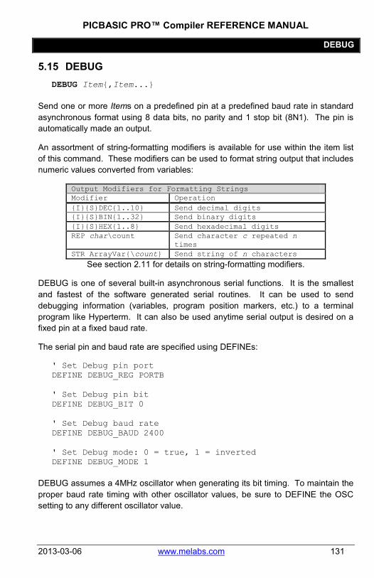
PICBASIC PRO™ Compiler REFERENCE MANUAL
DEBUG
2013-03-06 www.melabs.com 131
5.15 DEBUG DEBUG Item{,Item...}
Send one or more Items on a predefined pin at a predefined baud rate in standard asynchronous format using 8 data bits, no parity and 1 stop bit (8N1). The pin is automatically made an output.
An assortment of string-formatting modifiers is available for use within the item list of this command. These modifiers can be used to format string output that includes numeric values converted from variables:
Output Modifiers for Formatting Strings Modifier Operation {I}{S}DEC{1..10} Send decimal digits {I}{S}BIN{1..32} Send binary digits {I}{S}HEX{1..8} Send hexadecimal digits REP char\count Send character c repeated n
times STR ArrayVar{\count} Send string of n characters
See section 2.11 for details on string-formatting modifiers.
DEBUG is one of several built-in asynchronous serial functions. It is the smallest and fastest of the software generated serial routines. It can be used to send debugging information (variables, program position markers, etc.) to a terminal program like Hyperterm. It can also be used anytime serial output is desired on a fixed pin at a fixed baud rate.
The serial pin and baud rate are specified using DEFINEs:
' Set Debug pin port DEFINE DEBUG_REG PORTB ' Set Debug pin bit DEFINE DEBUG_BIT 0 ' Set Debug baud rate DEFINE DEBUG_BAUD 2400 ' Set Debug mode: 0 = true, 1 = inverted DEFINE DEBUG_MODE 1
DEBUG assumes a 4MHz oscillator when generating its bit timing. To maintain the proper baud rate timing with other oscillator values, be sure to DEFINE the OSC setting to any different oscillator value.

PICBASIC PRO™ Compiler REFERENCE MANUAL
DEBUG
132 www.melabs.com 2013-03-06
In some cases, the transmission rates of DEBUG instructions may present characters too quickly to the receiving device. A DEFINE adds character pacing to the serial output transmissions. This allows additional time between the characters as they are transmitted. The character pacing DEFINE allows a delay of up to 65,535 microseconds (65.535 milliseconds) between each character transmitted.
For example, to pause 1 millisecond between the transmission of each character:
DEFINE DEBUG_PACING 1000
While single-chip RS-232 level converters are common and inexpensive, thanks to current RS-232 implementation and the excellent I/O specifications of the PIC MCU, most applications may not require level converters. Rather, inverted TTL (DEBUG_MODE 1) may be used. A current limiting resistor is suggested (RS-232 is suppose to be short-tolerant).
DEBUG "B0=",DEC B0,10 ' Send the text "B0=" followed by the decimal value of B0 and a linefeed out serially

PICBASIC PRO™ Compiler REFERENCE MANUAL
DEBUGIN
2013-03-06 www.melabs.com 133
5.16 DEBUGIN DEBUGIN {Timeout, Label,}[Item{,Item...}]
Receive one or more Items on a predefined pin at a predefined baud rate in standard asynchronous format using 8 data bits, no parity and 1 stop bit (8N1). The pin is automatically made an input.
An optional Timeout and Label may be included to allow the program to continue if a character is not received within a certain amount of time. Timeout is specified in 1 millisecond units. If the serial input pin stays idle during the Timeout time, the program will exit the DEBUGIN command and jump to Label.
An assortment of string-parsing modifiers is available for use within the item list of this command. These modifiers are capable of extracting data from input strings to various variable types:
Input Modifiers for Parsing Strings Modifier Operation DEC{1..10} Receive decimal digits BIN{1..32} Receive binary digits HEX{1..8} Receive upper case hexadecimal
digits SKIP n Skip n received characters STR ArrayVar\n{\c} Receive string of n characters
optionally ended in character c WAIT ( ) Wait for sequence of characters WAITSTR ArrayVar{\n} Wait for character string
See section 2.10 for details on string-parsing modifiers.
DEBUGIN is one of several built-in asynchronous serial functions. It is the smallest and fastest of the software generated serial routines. It can be used to receive debugging information from a terminal program like Hyperterm. It can also be used anytime serial input is desired on a fixed pin at a fixed baud rate.
The serial pin and baud rate are specified using DEFINEs:

PICBASIC PRO™ Compiler REFERENCE MANUAL
DEBUGIN
134 www.melabs.com 2013-03-06
' Set Debugin pin port DEFINE DEBUGIN_REG PORTB ' Set Debugin pin bit DEFINE DEBUGIN_BIT 0 ' Set Debugin baud rate (same as Debug baud) DEFINE DEBUG_BAUD 2400 ' Set Debugin mode: 0 = true, 1 = inverted DEFINE DEBUGIN_MODE 1
If any of these DEFINEs are not included in a program, the DEBUGIN port, pin or mode is set to the same values as they are for DEBUG. The DEBUGIN baud rate is always the same as DEBUG's. It cannot be DEFINEd differently.
DEBUGIN assumes a 4MHz oscillator when generating its bit timing. To maintain the proper baud rate timing with other oscillator values, be sure to DEFINE the OSC setting to any different oscillator value.
While single-chip RS-232 level converters are common and inexpensive, thanks to current RS-232 implementation and the excellent I/O specifications of the PIC MCU, most applications may not require level converters. Rather, inverted TTL (DEBUGIN_MODE 1) may be used. A current limiting resistor is necessary to dissipate the higher and sometimes negative RS-232 voltage.
PICBASIC PRO™ Compiler REFERENCE MANUAL
DEBUGIN
2013-03-06 www.melabs.com 135
' Wait until the character "A" is received serially and put next character into B0
DEBUGIN [WAIT("A"),B0] ' Skip 2 chars and grab a 4 digit decimal number DEBUGIN [SKIP 2,DEC4 B0] ' Wait for value with timeout DEBUGIN 100, timesup, [B0]

PICBASIC PRO™ Compiler REFERENCE MANUAL
DO..LOOP
136 www.melabs.com 2013-03-06
5.17 DO..LOOP DO {UNTIL Condition} {WHILE Condition}
Statement... LOOP {UNTIL Condition} {WHILE Condition}
Repeatedly execute Statements in a loop. An optional UNTIL or WHILE may be added to check a Condition. Tests using the UNTIL keyword will cause the loop to terminate when the condition becomes true. Tests using the WHILE keyword will cause the loop to terminate when the condition becomes false.
If the test condition is written on the line with the DO keyword (at the top of the loop), the test will be performed before the loop executes. If the test condition results in termination of the loop, execution will continue at the line after the LOOP keyword, even if the code within the loop has not executed.
If the test condition is written on the line with the LOOP keyword (at the bottom of the loop), the test will first be performed after the loop executes. The code within the loop will always execute at least one time, even if the test condition calls for termination of the loop on its first iteration.
The EXIT command, when executed within a DO loop, will force the loop to terminate.

PICBASIC PRO™ Compiler REFERENCE MANUAL
DO..LOOP
2013-03-06 www.melabs.com 137
DO PWM PORTC.2,127,100
LOOP i = 1 DO SEROUT 0,N2400,["No:",#i,13,10]
i = i + 1 LOOP UNTIL i > 10 i = 1 DO WHILE i <= 10
SEROUT 0,N2400,["No:",#i,13,10] i = i + 1
LOOP i = 1 DO
SEROUT 0,N2400,["No:",#i,13,10] i = i + 1 IF PORTB.0 = 0 THEN EXIT
LOOP WHILE i <= 10

PICBASIC PRO™ Compiler REFERENCE MANUAL
DTMFOUT
138 www.melabs.com 2013-03-06
5.18 DTMFOUT DTMFOUT Pin,{Onms, Offms,}[Tone{,Tone...}]
Produce DTMF touch Tone sequence on Pin. Pin is automatically made an output. Pin may be a constant, 0-15, or a variable that contains a number 0-15 (e.g. B0) or a pin name (e.g. PORTA.0).
Onms is the number of milliseconds to sound each tone and Offms is the number of milliseconds to pause between each tone. If they are not specified, Onms defaults to 200ms and Offms defaults to 50ms.
Tones are numbered 0-15. Tones 0-9 are the same as on a telephone keypad. Tone 10 is the * key, Tone 11 is the # key and Tones 12-15 correspond to the extended keys A-D.
DTMFOUT uses FREQOUT to generate the dual tones. FREQOUT generates tones using a form of pulse width modulation. The raw data coming out of the pin looks pretty scary. Some kind of filter is usually necessary to smooth the signal to a sine wave and get rid of some of the harmonics that are generated:
DTMFOUT works best with a 20MHz or 40MHz oscillator. It can also work with a 10MHz or 8MHz oscillator and even at 4MHz, although it will start to get very hard to filter and be of fairly low amplitude. Any other frequency may not be used with DTMFOUT.
DTMFOUT is not supported on PIC MCUs that use the 12-bit instruction set due to RAM and stack constraints.
' Send DTMF tones for 212 on Pin1 DTMFOUT PORTB.1,[2,1,2]

PICBASIC PRO™ Compiler REFERENCE MANUAL
EEPROM
2013-03-06 www.melabs.com 139
5.19 EEPROM EEPROM {Location,}[Constant{,Constant...}]
This command is included for compatibility with other languages. The DATA command is recommended instead.
Store constants in on-chip EEPROM. If the optional Location value is omitted, the first EEPROM statement starts storing at address 0 and subsequent statements store at the following locations. If the Location value is specified, it denotes the starting location where these values are stored.
Constant can be a numeric constant or a string constant. Only the least significant byte of numeric values are stored. Strings are stored as consecutive bytes of ASCII values. No length or terminator is automatically added.
EEPROM only works with microcontrollers with on-chip EEPROM (Data Space). It will not work on devices with on-chip I2C interfaced serial EEPROM like the PIC12CE67x and PIC16CE62x parts. Since EEPROM is non-volatile memory, the data will remain intact even if the power is turned off.
The data is stored in the EEPROM space only once at the time the microcontroller is programmed, not each time the program is run. WRITE can be used to set the values of the on-chip EEPROM at runtime. READ is used to retrieve these stored DATA values at runtime.
' Store 10, 20 and 30 starting at location 4 EEPROM 4,[10,20,30]

PICBASIC PRO™ Compiler Reference Manual
END
140 www.melabs.com 2013-03-06
5.20 END END
Stop program execution and enter low power mode. All of the I/O pins remain in their current state. END works by executing a Sleep instruction continuously in a loop.
Care should be taken not to execute END while hardware peripherals such as a serial USART could be operating. END will suspend operation of such peripherals. If you need to suspend program operation without shutting down the peripherals, use STOP instead.
END

PICBASIC PRO™ Compiler REFERENCE MANUAL
ERASECODE
2013-03-06 www.melabs.com 141
5.21 ERASECODE ERASECODE Block
Some flash PIC MCUs, like the PIC18F series, require a portion of the code space to be erased before it can be rewritten with WRITECODE. On these devices, an erase is performed a block at a time. An erase block may be 32 words (64 bytes) or another size, depending on the device. This size is usually larger than the write block size. See the Microchip data sheet for information on the size of the erase block for the particular PIC MCU you are using.
The first location of the block to be erased is specified by Block. For PIC18F devices, Block is a byte address rather than a word address. Be careful not to specify a Block that contains program code.
Note that the Block address used in the ERASECODE command must coincide with a block starting address as defined by Microchip. If you use an address that is not a starting address, you may get unexpected results. If a PIC18 target device has an erase block size of 64 bytes, then the Block address should be an exact multiple of 64 (0, 64, 128, … 3200, 3264, etc.).
For 12-bit instruction set devices that support flash data memory, like the PIC12F519 and PIC16F526, ERASECODE must be used to erase the rows of memory before it can be rewritten using WRITE.
If only a portion of a block is to be changed, for example only the first byte in the block, the entire block must be read before it is erased and all of the data rewritten, including the new data and the original data that needs to be preserved.
Flash program writes must be enabled in the configuration for the PIC MCU at device programming time for ERASECODE to be able to erase.
Using this instruction on devices that do not support block erase may cause a compilation error.
ERASECODE $1000 ' Erase code block starting at location $1000

PICBASIC PRO™ Compiler REFERENCE MANUAL
EXIT
142 www.melabs.com 2013-03-06
5.22 EXIT EXIT
EXIT jumps to the line after the end of the currently-executing loop structure and continues program execution from there. This allows a loop to be terminated (aborted) with EXIT, overriding the loop's conditional requirement. As none of the loop structures in PBP use the stack, there are no stack concerns when using EXIT.
Types of loops that can be terminated using EXIT are:
DO..LOOP FOR..NEXT WHILE..WEND REPEAT..UNTIL
FOR x = 0 TO 255 IF (x = 27) THEN EXIT NEXT x
DO IF (PORTB.0 = 0) THEN EXIT LOOP

PICBASIC PRO™ Compiler REFERENCE MANUAL
FOR..NEXT
2013-03-06 www.melabs.com 143
5.23 FOR..NEXT FOR Count = Start TO End {STEP {-} Inc}{Body}NEXT {Count}
The FOR..NEXT loop allows programs to execute a number of statements (the Body) some number of times using a variable as a counter. Due to its complexity and versatility, FOR..NEXT is best described step by step:
1) The value of Start is assigned to the index variable, Count. Count can be a variable of any type.
2) The Body is executed. The Body is optional and can be omitted (perhaps for a delay loop).
3) The value of Inc is added to (or subtracted from if "-" is specified) Count. If no STEP clause is defined, Count is incremented by one.
4) If Count has not passed End or overflowed the variable type, execution returns to Step 2.
If the loop needs to Count to more than 255, a word- or long-sized (PBPL only) variable must be used.
FOR i = 1 TO 10 ' Count from 1 to 10 SEROUT 0,N2400,[#i," "] ' Send each number toPin0
serially NEXT i ' Go back to and do next count SEROUT 0,N2400,[10] ' Send a linefeed FOR B2 = 20 TO 10 STEP -2 ' Count from 20 to 10 by 2
SEROUT 0,N2400,[#B2," "] ' Send each number to Pin0 serially
NEXT B2 ' Go back to and do next count SEROUT 0,N2400,[10] ' Send a linefeed

PICBASIC PRO™ Compiler REFERENCE MANUAL
FREQOUT
144 www.melabs.com 2013-03-06
5.24 FREQOUT FREQOUT Pin, Onms, Frequency1{,Frequency2}
Produce the Frequency(s) on Pin for Onms milliseconds. Pin is automatically made an output. Pin may be a constant, 0-15, or a variable that contains a number 0-15 (e.g. B0) or a pin name (e.g. PORTA.0).
One or two different frequencies from 0 to 32767 Hertz may be produced at a time.
FREQOUT generates tones using a form of pulse width modulation. The raw data coming out of the pin looks pretty scary. Some kind of filter is usually necessary to smooth the signal to a sine wave and get rid of some of the harmonics that are generated:
FREQOUT works best with a 20MHz or 40MHz oscillator. It can also work with a 10MHz or 8MHz oscillator and even at 4MHz, although it will start to get very hard to filter and be of fairly low amplitude. Any other frequency will cause FREQOUT to generate a frequency that is a ratio of the actual oscillator used and 20MHz.
FREQOUT is not supported on 12-bit core PIC MCUs due to RAM and stack constraints.
' Send 1KHz tone on Pin1 for 2 seconds FREQOUT PORTB.1,2000,1000 ' Send 350Hz / 440Hz (Dial Tone) for 2 seconds FREQOUT PORTB.1,2000,350,440

PICBASIC PRO™ Compiler REFERENCE MANUAL
GOSUB
2013-03-06 www.melabs.com 145
5.25 GOSUB GOSUB Label
Jump to the subroutine at Label saving its return address on the stack. Unlike GOTO, when a RETURN statement is reached after executing a GOSUB, execution resumes with the statement following that last executed GOSUB statement.
An unlimited number of subroutines may be used in a program. Subroutines may also be nested. In other words, it is possible for a subroutine to GOSUB to another subroutine. Such subroutine nesting must be restricted to no more than four nested levels for 12- and 14-bit core devices, 12 levels for 14-bit enhanced core and PIC17 parts and 27 levels for PIC18 parts. Interrupts cause additional locations to be used on the stack , reducing the number of possible nested GOSUBs.
See section 7.5 Hardware Stack for more information.
GOSUB flash 'Execute subroutine named flash flash:
HIGH led 'Turn on LED PAUSE 500 'Pause 500mS LOW led 'Turn off LED
RETURN 'Go back to main routine that called us

PICBASIC PRO™ Compiler REFERENCE MANUAL
GOTO
146 www.melabs.com 2013-03-06
5.26 GOTO GOTO Label
Program execution continues with the statements at Label.
GOTO send ' Jump to statement labeled send ...
send:
SEROUT 0,N2400,["Hi"] ' Send "Hi" out Pin0 serially

PICBASIC PRO™ Compiler REFERENCE MANUAL
HIGH
2013-03-06 www.melabs.com 147
5.27 HIGH HIGH Pin
Make the specified Pin high. Pin is automatically made an output. Pin may be a constant, 0-15, or a variable that contains a number 0-15 (e.g. B0) or a pin name (e.g. PORTA.0).
HIGH 0 ' Make Pin0 an output and set it high (~5 volts)
HIGH PORTA.0 ' Make PORTA, pin 0 an output and set it high (~5 volts)
led Var PORTB.0 ' Define LED pin HIGH led ' Make LED pin an output and set
it high (~5 volts)
Alternatively, if the pin is already an output, a much quicker and shorter way (from a generated code standpoint) to set it high would be:
PORTB.0 = 1 ' Set PORTB pin 0 high
Since this command automatically sets the data-direction of the pin it acts on, the Pin parameter should only be a PORT or GPIO register (or an alias to a PORT or GPIO register). If the command is directed to act upon a LAT output or a bit within a variable or SFR, it will attempt to set a data-direction register that doesn't exist. The result may be unexpected behavior since a bit is changed in a seemingly random memory location. This can be very difficult to debug.

PICBASIC PRO™ Compiler REFERENCE MANUAL
HPWM
148 www.melabs.com 2013-03-06
5.28 HPWM HPWM Channel, Dutycycle, Frequency
Output a pulse width modulated pulse train using PWM hardware available on some PIC MCUs. It can run continuously in the background while the program is executing other instructions.
Channel specifies which hardware PWM channel to use. Some devices have between 1 and 5 PWM Channels that can be used with HPWM. The Microchip data sheet for the particular device shows the fixed hardware pin for each Channel. For example, for a PIC16F877a, Channel 1 is CCP1 which is pin PORTC.2. Channel 2 is CCP2 which is pin PORTC.1.
Some devices can be configured to select different pins for some PWM output channels. The following DEFINEs allow you to specify alternative output pins so that the HPWM command will function correctly. (The available pin selection is specified in the Microchip datasheet for the target device. These DEFINEs only serve to let PBP know how you have configured the microcontroller. Additional register settings will be required to actually relocate the pins.)
DEFINE CCP1_REG PORTC 'Channel-1 port DEFINE CCP1_BIT 2 'Channel-1 bit DEFINE CCP2_REG PORTC 'Channel-2 port DEFINE CCP2_BIT 1 'Channel-2 bit DEFINE CCP3_REG PORTG 'Channel-3 port DEFINE CCP3_BIT 0 'Channel-3 bit DEFINE CCP4_REG PORTG 'Channel-4 port DEFINE CCP4_BIT 3 'Channel-4 bit DEFINE CCP5_REG PORTG 'Channel-5 port DEFINE CCP5_BIT 4 'Channel-5 bit
Dutycycle specifies the on/off (high/low) ratio of the signal. It ranges from 0 to 255, where 0 is off (low all the time) and 255 is on (high) all the time. A value of 127 gives a 50% duty cycle (square wave).
Frequency is the desired frequency of the PWM signal. On devices with 2 channels, the Frequency must be the same on both channels. Not all frequencies are available at all oscillator settings. For the non-long versions of PBP (PBP and PBPW), the highest frequency at any oscillator speed is 32767Hz.

PICBASIC PRO™ Compiler REFERENCE MANUAL
HPWM
2013-03-06 www.melabs.com 149
The lowest usable HPWM Frequency at each oscillator setting is shown in the following table.
OSC 14-bit Enhanced 14-bit PIC18
4MHz 245Hz 62Hz 245Hz 8MHz 489Hz 123Hz 489Hz
10MHz 611Hz 153Hz 611Hz
12MHz 733Hz 184Hz 733Hz
16MHz 977Hz 245Hz 977Hz
20MHz 1221Hz 306Hz 1221Hz
24MHz na 366Hz 1465Hz
25MHz na 382Hz 1527Hz
32MHz na 489Hz 1953Hz
33MHz na na 2015Hz
40MHz na na 2441Hz
48MHz na na 2929Hz
64MHz na na 3905Hz
After an HPWM command, the CCP control register is left in PWM mode. If the CCP pin is to be used as a normal I/O pin after an HPWM command, the CCP control register will need to be set to PWM off. See the Microchip data sheet for the particular device for more information.
Many devices allow a selection of Timer resource for some or all of the PWM channels. The HPWM command will automatically determine the preset Timer selection upon execution. Note that PWM channels that share a single timer may not operate at independent output frequencies. While duty-cycle settings are always independent from one channel to the next, independent frequency settings require independent timer resources.
HPWM 1,127,1000 ' Send a 50% duty cycle PWM signal at 1kHz
HPWM 1,64,2000 ' Send a 25% duty cycle PWM signal at 2kHz

PICBASIC PRO™ Compiler REFERENCE MANUAL
HSERIN
150 www.melabs.com 2013-03-06
5.29 HSERIN HSERIN {ParityLabel,} {Timeout, Label,}[Item{,...}]
Receive one or more Items from the hardware serial port on devices that support asynchronous serial communications in hardware.
HSERIN is one of several built-in asynchronous serial functions. It can only be used with devices that have a hardware USART. See the device data sheet for information on the serial input pin and other parameters. The serial parameters and baud rate are specified using DEFINEs:
' Set receive register to receiver enabled DEFINE HSER_RCSTA 90h ' Set transmit register to transmitter enabled DEFINE HSER_TXSTA 20h ' Set baud rate DEFINE HSER_BAUD 2400 ' Set SPBRG, SPBRGH directly ' (better to set HSER_BAUD instead) DEFINE HSER_SPBRG 25 DEFINE HSER_SPBRGH 0
HSER_RCSTA, HSER_TXSTA, HSER_SPBRG, and HSER_SPBRGH simply set each respective PIC MCU register, RCSTA, TXSTA, SPBRG and SPBRGH to the hexadecimal value DEFINEd, once, at the beginning of the program. See the Microchip data sheet for the device for more information on each of these registers.
The TXSTA register BRGH bit (bit 2) controls the high speed mode for the baud rate generator. Certain baud rates at certain oscillator speeds require this bit to be set to operate properly. To do this, set HSER_TXSTA to 24h instead of 20h. All baud rates at all oscillator speeds may not be supported by the device. See the Microchip data sheet for the hardware serial port baud rate tables and additional information.
HSERIN assumes a 4MHz oscillator when calculating the baud rate. To maintain the proper baud rate timing with other oscillator values, be sure to DEFINE the OSC setting to the new oscillator value.
An optional Timeout and Label may be included to allow the program to continue if a character is not received within a certain amount of time.
Timeout is specified in 1 millisecond units. If no character is received during the Timeout time, the program will exit the HSERIN command and jump to Label.

PICBASIC PRO™ Compiler REFERENCE MANUAL
HSERIN
2013-03-06 www.melabs.com 151
The serial data format defaults to 8N1, 8 data bits, no parity bit and 1 stop bit. 7E1 (7 data bits, even parity, 1 stop bit) or 7O1 (7data bits, odd parity, 1 stop bit) can be enabled using one of the following DEFINEs:
' Use only if even parity desired DEFINE HSER_EVEN 1 ' Use only if odd parity desired DEFINE HSER_ODD 1 ' Use 8 bits + parity DEFINE HSER_BITS 9
The parity setting, along with all of the other HSER DEFINEs, affect both HSERIN and HSEROUT.
An optional ParityLabel may be included in the statement. The program will continue at this location if a character with a parity error is received. It should only be used if parity is enabled using one of the preceding DEFINEs.
As the hardware serial port only has a 2 byte input buffer, it can easily overflow if characters are not read from it often enough. When this happens, the USART stops accepting new characters and needs to be reset. This overflow error can be reset by toggling the CREN bit in the RCSTA register. A DEFINE can be used to automatically clear this error. However, you will not know that an error has occurred and characters may have been lost.
DEFINE HSER_CLROERR 1 ' Clear overrun error upon execution of every HSERIN command
To manually clear an overrun error:
RCSTA.4 = 0 RCSTA.4 = 1
The HSERIN command does not offer a parameter to select the idle state of the input signal. By default, the USART peripheral will interpret the input signal in TRUE mode (idle state being high at the input pin). A few devices offer a selectable polarity via register settings. For most devices, though, any signal inversion must be accomplished with external circuity.
On devices with 2 hardware serial ports, HSERIN will only use the first port. The second port may read using HSERIN2.

PICBASIC PRO™ Compiler REFERENCE MANUAL
HSERIN
152 www.melabs.com 2013-03-06
An assortment of string-parsing modifiers is available for use within the item list of this command. These modifiers are capable of extracting data from input strings to various variable types:
Input Modifiers for Parsing Strings Modifier Operation DEC{1..10} Receive decimal digits BIN{1..32} Receive binary digits HEX{1..8} Receive upper case hexadecimal
digits SKIP n Skip n received characters STR ArrayVar\n{\c} Receive string of n characters
optionally ended in character c WAIT ( ) Wait for sequence of characters WAITSTR ArrayVar{\n} Wait for character string
See section 2.10 for details on string-parsing modifiers.
HSERIN [B0,DEC W1] HSERIN 100, timesup, [B0]

PICBASIC PRO™ Compiler REFERENCE MANUAL
HSERIN2
2013-03-06 www.melabs.com 153
5.30 HSERIN2 HSERIN2 {ParityLabel,}{Timeout, Label,}[Item{,...}]
Receive one or more Items from the second hardware serial port on devices that support asynchronous serial communications in hardware.
HSERIN2 works the same as HSERIN with the exception that is uses the second hardware serial port on devices that have 2 ports such as the PIC18F8720 It can only be used with devices that have 2 hardware USARTs. See the device data sheet for information on the serial output pin and other parameters and the above section on HSERIN for more command details. The serial parameters and baud rate are specified using DEFINEs:
' Set receive register to receiver enabled DEFINE HSER2_RCSTA 90h ' Set transmit register to transmitter enabled DEFINE HSER2_TXSTA 20h ' Set baud rate DEFINE HSER2_BAUD 2400 ' Set SPBRG2, SPBRGH2 directly ' (better to set HSER2_BAUD instead) DEFINE HSER2_SPBRG 25 DEFINE HSER2_SPBRGH 0 ' Use only if even parity desired DEFINE HSER2_EVEN 1 ' Use only if odd parity desired DEFINE HSER2_ODD 1 ' Use 8 bits + parity DEFINE HSER2_BITS 9 ' Automatically clear overflow errors DEFINE HSER2_CLROERR 1 HSERIN2 [B0,DEC W1] HSERIN2 100, timesup, [B0]

PICBASIC PRO™ Compiler REFERENCE MANUAL
HSEROUT
154 www.melabs.com 2013-03-06
5.31 HSEROUT HSEROUT [Item{,Item...}]
Send one or more Items to the hardware serial port on devices that support asynchronous serial communications in hardware.
HSEROUT is one of several built-in asynchronous serial functions. It can only be used with devices that have a hardware USART. See the device data sheet for information on the serial output pin and other parameters. The serial parameters and baud rate are specified using DEFINEs:
' Set receive register to receiver enabled DEFINE HSER_RCSTA 90h ' Set transmit register to transmitter enabled DEFINE HSER_TXSTA 20h ' Set baud rate DEFINE HSER_BAUD 2400 ' Set SPBRG, SPBRGH directly ' (better to set HSER_BAUD instead) DEFINE HSER_SPBRG 25 DEFINE HSER_SPBRGH 0
HSER_RCSTA, HSER_TXSTA, HSER_SPBRG, and HSER_SPBRGH simply set each respective PIC MCU register, RCSTA, TXSTA, SPBRG and SPBRGH to the hexadecimal value DEFINEd, once, at the beginning of the program. See the Microchip data sheet for the device for more information on each of these registers.
The TXSTA register BRGH bit (bit 2) controls the high speed mode for the baud rate generator. Certain baud rates at certain oscillator speeds require this bit to be set to operate properly. To do this, set HSER_TXSTA to 24h instead of 20h. All baud rates at all oscillator speeds may not be supported by the device. See the Microchip data sheet for the hardware serial port baud rate tables and additional information.
HSEROUT assumes a 4MHz oscillator when calculating the baud rate. To maintain the proper baud rate timing with other oscillator values, be sure to DEFINE the OSC setting to the new oscillator value.
The serial data format defaults to 8N1, 8 data bits, no parity bit and 1 stop bit. 7E1 (7 data bits, even parity, 1 stop bit) or 7O1 (7data bits, odd parity, 1 stop bit) can be enabled using one of the following DEFINEs:

PICBASIC PRO™ Compiler REFERENCE MANUAL
HSEROUT
2013-03-06 www.melabs.com 155
' Use only if even parity desired DEFINE HSER_EVEN 1 ' Use only if odd parity desired DEFINE HSER_ODD 1 ' Use 8 bits + parity DEFINE HSER_BITS 9
The parity setting, along with all of the other HSER DEFINEs, affect both HSERIN and HSEROUT.
Since the serial transmission is done in hardware, it is not possible to set the levels to an inverted state to eliminate an RS-232 driver. Therefore a suitable driver should be used with HSEROUT.
On devices with 2 hardware serial ports, HSEROUT will only use the first port. The second port may be accessed using HSEROUT2.
An assortment of string-formatting modifiers is available for use within the item list of this command. These modifiers can be used to format string output that includes numeric values converted from variables:
Output Modifiers for Formatting Strings Modifier Operation {I}{S}DEC{1..10} Send decimal digits {I}{S}BIN{1..32} Send binary digits {I}{S}HEX{1..8} Send hexadecimal digits REP char\count Send character c repeated n
times STR ArrayVar{\count} Send string of n characters
See section 2.11 for details on string-formatting modifiers.
HSEROUT [DEC B0,10] ' Send the decimal value of B0 followed by a line feed out the hardware USART

PICBASIC PRO™ Compiler REFERENCE MANUAL
HSEROUT2
156 www.melabs.com 2013-03-06
5.32 HSEROUT2 HSEROUT2 [Item{,Item...}]
Send one or more Items to the second hardware serial port on devices that support asynchronous serial communications in hardware.
HSEROUT2 works the same as HSEROUT with the exception that is uses the second hardware serial port on devices that have 2 ports such as the PIC18F8720. It can only be used with devices that have 2 hardware USARTs. See the device data sheet for information on the serial output pin and other parameters and the above section on HSEROUT for more command details. The serial parameters and baud rate are specified using DEFINEs:
' Set receive register to receiver enabled DEFINE HSER2_RCSTA 90h ' Set transmit register to transmitter enabled DEFINE HSER2_TXSTA 20h ' Set baud rate DEFINE HSER2_BAUD 2400 ' Set SPBRG2, SPBRGH2 directly ' (better to set HSER2_BAUD instead) DEFINE HSER2_SPBRG 25 DEFINE HSER2_SPBRGH 0 ' Use only if even parity desired DEFINE HSER2_EVEN 1 ' Use only if odd parity desired DEFINE HSER2_ODD 1 ' Use 8 bits + parity DEFINE HSER2_BITS 9 HSEROUT2 [DEC B0,10] ' Send the decimal value of B0
followed by a linefeed out the hardware USART

PICBASIC PRO™ Compiler REFERENCE MANUAL
I2CREAD
2013-03-06 www.melabs.com 157
5.33 I2CREAD I2CREAD DataPin, ClockPin, Control,{Address,}[Var{,Var...}]{,Label}
Send Control and optional Address bytes out the ClockPin and DataPin and store the byte(s) received into Var. ClockPin and DataPin may be a constant, 0-15, or a variable that contains a number 0-15 (e.g. B0) or a pin name (e.g. PORTA.0).
I2CREAD is a software-based command and does not require that the target device have I2C capability. The ClockPin and DataPin parameters may be set to any digital I/O pins, and may be different in different commands within the same program.
I2CREAD and I2CWRITE can be used to read and write data to a serial EEPROM with a 2-wire I2C interface such as the Microchip 24LC01B and similar devices. This allows data to be stored in external non-volatile memory so that it can be maintained even after the power is turned off. These commands operate in the I2C master mode and may also be used to talk to other devices with an I2C interface like temperature sensors and A/D converters.
For 12-bit core PIC MCUs only, the I2C clock and data pins are fixed at compile time by DEFINEs. They still must be specified in the I2CREAD statements, though this information is ignored by the compiler.
DEFINE I2C_SCL PORTA,1 ' For 12-bit core only DEFINE I2C_SDA PORTA,0 ' For 12-bit core only
The upper 7 bits of the Control byte contain the control code along with chip select or additional address information, depending on the particular device. The low order bit is an internal flag indicating whether it is a read or write command and should be kept clear.
This format for the Control byte is different than the format used by the original PICBASIC Compiler. Be sure to use this format with PBP I2C operations.
For example, when communicating with a 24LC01B, the control code is %1010 and the chip selects are unused so the Control byte would be %10100000 or $A0. Formats of Control bytes for some of the different parts follows:

PICBASIC PRO™ Compiler REFERENCE MANUAL
I2CREAD
158 www.melabs.com 2013-03-06
Device Capacity Control Address size
24LC01 B 128 bytes %1010xxx0 1 byte
24LC02 B 256 bytes %1010xxx0 1 byte
24LC04 B 512 bytes %1010xxb0 1 byte
24LC08 B 1K bytes %1010xbb0 1 byte
24LC16 B 2K bytes %1010bbb0 1 byte
24LC32 B 4K bytes %1010ddd0 2 bytes
24LC65 8K bytes %1010ddd0 2 bytes bbb = block select (high order address) bits ddd = device select bits xxx = don't care
The Address size sent (byte or word) is determined by the size of the variable that is used. If a byte-sized variable is used for the Address, an 8-bit address is sent. If a word-sized variable is used, a 16-bit address is sent. Be sure to use the proper sized variable for the device you wish to communicate with. Constants should not be used for the Address as the size can vary dependent on the size of the constant. Also, expressions should not be used as they can cause an improper Address size to be sent.
Once Control and/or Address has been sent to the device, the data specified between the square brackets is read from the device. If a word-or long-sized Var is specified, the bytes are read and stored into the Var highest byte first, followed by the lower byte(s). This order is different than the way variables are normally stored, low byte first.
A modifier, STR, may be included before the variable name. This can load an entire array (string) at once. If STR is specified, the following variable must be the name of a word or byte array, followed by a backslash (\) and a count:
a Var Byte[8] addr Var Byte
addr = 0 I2CREAD PORTC.4,PORTC.3,$a0,addr,[STR a\8]
If a word- or long-sized array is specified, the bytes that comprise each element are read lowest byte first. This is the opposite of how simple words and longs are read and is consistent with the way the compiler normally stores word- and long-sized variables.
If the optional Label is included, this label will be jumped to if an acknowledge is not received from the I2C device. The I2C instructions can be used to access the on-chip serial EEPROM on the PIC12CE and PIC16CE devices. Simply specify the

PICBASIC PRO™ Compiler REFERENCE MANUAL
I2CREAD
2013-03-06 www.melabs.com 159
pin names for the appropriate internal lines as part of the I2C command and place the following DEFINE at the top of the program:
DEFINE I2C_INTERNAL 1
For the PIC12CE67x devices, the data line is GPIO.6 and the clock line is GPIO.7. For the PIC16CE62x devices, the data line is EEINTF.1 and the clock line is EEINTF.2. See the Microchip data sheets for these devices for more information.
The timing of the I2C instructions is set so that standard speed devices(100kHz) will be accessible at clock speeds up to 8MHz. Fast mode devices (400kHz) may be used up to 20MHz. If it is desired to access a standard speed device at above 8MHz, the following DEFINE should be added to the program:
DEFINE I2C_SLOW 1
Because of memory and stack constraints, this DEFINE for 12-bit core PIC MCUs does not do anything. Low-speed (100 kHz) I2C devices may be used up to 4MHz. Above 4MHz, high-speed (400kHz) devices should be used.
Transfer on the I2C bus can be paused by the receiving device by its holding the clock line low (not supported on 12-bit core PIC MCUs). To enable this the following DEFINE should be added to the program:
DEFINE I2C_HOLD 1
To make the I2C clock line bipolar instead of open-collector the following DEFINE may be added to the program:
DEFINE I2C_SCLOUT 1

PICBASIC PRO™ Compiler REFERENCE MANUAL
I2CREAD
160 www.melabs.com 2013-03-06
The I2C clock and data lines should be pulled up to Vcc with a 4.7K resistor per the following schematic as they are both run in a bidirectional open-collector manner.
Circuit example for common memory device:
See the Microchip "Non-Volatile Memory Products Data Book" for more information on these and other devices that may be used with the I2CREAD and I2CWRITE commands.
addr VAR BYTE cont CON %10100000 addr = 17 ' Set address to 17 ' Read data at address 17 into B2 I2CREAD PORTA.0,PORTA.1,cont,addr,[B2]
PICBASIC PRO™ Compiler REFERENCE MANUAL
I2CWRITE
2013-03-06 www.melabs.com 161
5.34 I2CWRITE I2CWRITE DataPin, ClockPin, Control, {Address,}[Value{,Value...}]{,Label}
I2CWRITE sends Control and optional Address out the I2C ClockPin and DataPin followed by Value. ClockPin and DataPin may be a constant, 0-15, or a variable that contains a number 0-15 (e.g. B0) or a pin name (e.g. PORTA.0).
I2CWRITE is a software-based command and does not require that the target device have I2C capability. The ClockPin and DataPin parameters may be set to any digital I/O pins, and may be different in different commands within the same program.
For 12-bit core PIC MCUs only, the I2C clock and data pins are fixed at compile time by DEFINEs. They still must be specified in the I2CWRITE statements, though this information is ignored by the compiler.
DEFINE I2C_SCL PORTA,1 ' For 12-bit core only DEFINE I2C_SDA PORTA,0 ' For 12-bit core only
The Address size sent (byte or word) is determined by the size of the variable that is used. If a byte-sized variable is used for the Address, an 8-bit address is sent. If a word-sized variable is used, a 16-bit address is sent. Be sure to use the proper sized variable for the device you wish to communicate with. Constants should not be used for the Address as the size can vary dependent on the size of the constant. Also, expressions should not be used as they can cause an improper Address size to be sent.
When writing to a serial EEPROM, it is necessary to wait 10ms (device dependent - check its data sheet) for the write to complete before attempting communication with the device again. If a subsequent I2CREAD or I2CWRITE is attempted before the write is complete, the access will be ignored.
While a single I2CWRITE statement may be used to write multiple bytes at once, doing so may violate the above write timing requirement for serial EEPROMs. Some serial EEPROMS let you write multiple bytes into a single page before necessitating the wait. Check the data sheet for the specific device you are using for these details. The multiple byte write feature may also be useful with I2C devices other than serial EEPROMs that don't have to wait between writes.
If a word- or long-sized Value is specified, the bytes are sent highest byte first, followed by the lower byte(s). This order is different than the way variables are normally stored, low byte first.

PICBASIC PRO™ Compiler REFERENCE MANUAL
I2CWRITE
162 www.melabs.com 2013-03-06
A modifier, STR, may be included before the variable name. This can be used to write an entire array (string) at once and take advantage of a serial EEPROM's page mode. The data must fit into a single SEEPROM page. The page size is dependent on the particular SEEPROM device. If STR is specified, the following variable must be the name of a word or byte array, followed by a backslash (\) and a count:
a Var Byte[8] addr Var Byte addr = 0 I2CWRITE PORTC.4,PORTC.3,$a0,addr,[STR a\8]
If a word- or long-sized array is specified, the bytes that comprise each element are written lowest byte first. This is the opposite of how simple words and longs are written and is consistent with the way the compiler normally stores word- and long-sized variables.
If the optional Label is included, this label will be jumped to if an acknowledge is not received from the I2C device. The I2C instructions can be used to access the on-chip serial EEPROM on the PIC12CE and PIC16CE devices. Simply specify the pin names for the appropriate internal lines as part of the I2C command and place the following DEFINE at the top of the program:
DEFINE I2C_INTERNAL 1
For the PIC12CE67x devices, the data line is GPIO.6 and the clock line is GPIO.7. For the PIC16CE62x devices, the data line is EEINTF.1 and the clock line is EEINTF.2. See the Microchip data sheets for these devices for more information.
The timing of the I2C instructions is set so that standard speed devices(100kHz) will be accessible at clock speeds up to 8MHz. Fast mode devices (400kHz) may be used up to 20MHz. If it is desired to access a standard speed device at above 8MHz, the following DEFINE should be added to the program:
DEFINE I2C_SLOW 1
Because of memory and stack constraints, this DEFINE for 12-bit core PIC MCUs does not do anything. Low-speed (100 kHz) I2C devices may be used up to 4MHz. Above 4MHz, high-speed (400kHz) devices should be used.

PICBASIC PRO™ Compiler REFERENCE MANUAL
I2CWRITE
2013-03-06 www.melabs.com 163
Transfer on the I2C bus can be paused by the receiving device by its holding the clock line low (not supported on 12-bit core PIC MCUs). To enable this the following DEFINE should be added to the program:
DEFINE I2C_HOLD 1
To make the I2C clock line bipolar instead of open-collector the following DEFINE may be added to the program:
DEFINE I2C_SCLOUT 1
See the I2CREAD command above for the rest of the story.
addr Var Byte cont Con %10100000 addr = 17 ' Set address to 17 ' Send the byte 6 to address 17 I2CWRITE PORTA.0,PORTA.1,cont,addr,[6] Pause 10 ' Wait 10ms for write to completeaddr = 1 ' Set address to 1 ' Send the byte in B2 to address 1 I2CWRITE PORTA.0,PORTA.1,cont,addr,[B2] Pause 10 ' Wait 10ms for write to complete

PICBASIC PRO™ Compiler REFERENCE MANUAL
IF..THEN
164 www.melabs.com 2013-03-06
5.35 IF..THEN IF Comp {AND/OR Comp...} THEN Label IF Comp {AND/OR Comp...} THEN Statement... IF Comp {AND/OR Comp...} THEN
Statement... {ELSEIF Comp {AND/OR Comp...} THEN
Statement...} {ELSE
Statement...} ENDIF
Performs one or more comparisons. Each Comp term can relate a variable to a constant or other variable and includes one of the comparison operators listed previously.
IF..THEN evaluates the comparison terms for true or false. If the condition evaluates to true, the operation after the THEN is executed. If it evaluates to false, the operation after the THEN is not executed. Comparisons that evaluate to 0 are considered false. Any other value is considered true.
For PBPW, all values in comparisons are treated as unsigned. IF..THEN cannot be used to check if a number is less than 0. Using PBPL, signed comparisons, including less than zero, may be performed.
It is essential to use parenthesis to specify the order in which the operations should be tested. Otherwise, operator precedence will determine it for you and the result may not be as expected.
IF..THEN can operate as a single-line or code, or as a multi-line block structure.
If written as a single line, a label may be written after the THEN keyword. The IF statement will jump to the label if the condition evaluates as true:
IF PORTB.0 = 0 THEN pushd ' If the condition is true, jump to label pushd
Single line mode can also be used to execute a command statement, or multiple, concatenated command statements.
IF PORTB.0 = 0 THEN HIGH PORTC.0
In the multi-line form, IF..THEN can conditionally execute a group of Statements following the THEN. This is the traditional form found in many programming languages. This form requires that the THEN keyword be the last word on the line.

PICBASIC PRO™ Compiler REFERENCE MANUAL
IF..THEN
2013-03-06 www.melabs.com 165
The Statements must be placed on separate lines and followed by an optional ELSEIF or ELSE and required ENDIF to complete the structure.
Only one block of code will be executed, even if multiple ELSEIF conditions evaluate as true. The first condition that evaluates as true will cause subsequent conditionals to be ignored.
IF B0 = 20 THEN led = 1
ELSEIF B0 = 40 THEN led = 1
ELSE led = 0
ENDIF
More Examples:
IF B0 <> 10 THEN B0 = B0 + 1 B1 = B1 - 1
ENDIF IF B0 = 20 THEN
led = 1 ELSE
led = 0 ENDIF IF B0 >= 40 THEN old IF PORTB.0 THEN itson IF (B0 = 10) AND (B1 = 20) THEN mainloop IF B0 <> 10 THEN B0 = B0 + 1: B1 = B1 - 1
PICBASIC PRO™ Compiler REFERENCE MANUAL
INPUT
166 www.melabs.com 2013-03-06
5.36 INPUT INPUT Pin
Makes the specified Pin an input. Pin may be a constant, 0-15, or a variable that contains a number 0-15 (e.g. B0) or a pin name (e.g. PORTA.0).
INPUT 0 ' Make Pin0 an input INPUT PORTA.0 ' Make PORTA, pin 0 an input
Alternatively, the pin may be set to an input using direct register access:
TRISB.0 = 1 ' Set PORTB, pin 0 to an input
All of the pins on a port may be set to inputs by setting the entire TRIS register at once:
TRISB = %11111111 ' Set all of PORTB to inputs
INPUT is most useful for setting a pin to input using only the pin's alias. It is not necessary to know the actual port.pin designation in this case:
user_in VAR PORTB.0 ' Alias user input pin INPUT user_in ' Set to input
Since this command automatically sets the data-direction of the pin it acts on, the Pin parameter should only be a PORT or GPIO register (or an alias to a PORT or GPIO register). If the command is directed to act upon a LAT output or a bit within a variable or SFR, it will attempt to set a data-direction register that doesn't exist. The result may be unexpected behavior since a bit is changed in a seemingly random memory location. This can be very difficult to debug.

PICBASIC PRO™ Compiler REFERENCE MANUAL
LCDIN
2013-03-06 www.melabs.com 167
5.37 LCDIN LCDIN {Address,}[Var{,Var...}]
Read LCD RAM at Address and store data to Var.
LCDs have RAM onboard that is used for character memory. Most LCDs have more RAM available that is necessary for the displayable area. This RAM can be written using the LCDOUT instruction. The LCDIN instruction allows this RAM to be read.
CG (character generator) RAM runs from address $40 to $7f. Display data RAM starts at address $80. See the data sheet for the specific LCD for these addresses and functions.
It is necessary to connect the LCD read/write line to a PIC MCU pin so that it may be controlled to select either a read (LCDIN) or write (LCDOUT) operation. Two DEFINEs control the pin address:
DEFINE LCD_RWREG PORTE ' LCD read/write port DEFINE LCD_RWBIT 2 ' LCD read/write pin bit
See LCDOUT for information on connecting an LCD to a PIC MCU.
LCDIN [B0]

PICBASIC PRO™ Compiler REFERENCE MANUAL
LCDOUT
168 www.melabs.com 2013-03-06
5.38 LCDOUT LCDOUT Item{,Item...}
Display Items on an intelligent Liquid Crystal Display. PBP supports LCD modules with a Hitachi 44780 controller or equivalent. These LCDs usually have a 14- or 16-pin single- or dual-row header at one edge.
An assortment of string-formatting modifiers is available for use within the item list of this command. These modifiers can be used to format string output that includes numeric values converted from variables:
Output Modifiers for Formatting Strings Modifier Operation {I}{S}DEC{1..10} Send decimal digits {I}{S}BIN{1..32} Send binary digits {I}{S}HEX{1..8} Send hexadecimal digits REP char\count Send character c repeated n
times STR ArrayVar{\count} Send string of n characters
See section 2.11 for details on string-formatting modifiers.
A program should wait for up to half a second before sending the first command to an LCD. It can take quite a while for an LCD to start up.
The LCD is initialized the first time any character or command is sent to it using LCDOUT. If it is powered down and then powered back up for some reason during operation, an internal flag can be reset to tell the program to reinitialize it the next time it uses LCDOUT:
FLAGS = 0
Commands are sent to the LCD by sending a $FE followed by the command. Some useful commands are listed in the following table.

PICBASIC PRO™ Compiler REFERENCE MANUAL
LCDOUT
2013-03-06 www.melabs.com 169
Command Operation
$FE, $01 Clear display $FE, $02 Return home $FE, $0C Cursor off $FE, $0E Underline cursor on $FE, $0F Blinking cursor on $FE, $10 Move cursor left one position $FE, $14 Move cursor right one position $FE, $80 Move cursor to beginning of first
line $FE, $C0 Move cursor to beginning of second
line $FE, $94 Move cursor to beginning of third
line $FE, $D4 Move cursor to beginning of fourth
line
Note that there are commands to move the cursor to the beginning of the different lines of a multi-line display. For most LCDs, the displayed characters and lines are not consecutive in display memory - there can be a break in between locations. For most 16x2 displays, the first line starts at $80 and the second line starts at $C0. The command:
LCDOUT $FE, $80 + 4
sets the display to start writing characters at the forth position of the first line. 16x1 displays are usually formatted as 8x2 displays with a break between the memory locations for the first and second 8 characters. 4line displays also have a mixed up memory map, as shown in the table above.
See the data sheet for the particular LCD device for the character memory locations and additional commands..
LCDOUT $FE, 1, "Hello" ' Clear display and show "Hello" LCDOUT $FE, $C0, "World" ' Jump to second line and show
"World" LCDOUT B0,#B1 ' Display B0 and decimal ASCII
value of B1
The LCD may be connected to the PIC MCU using either a 4-bit bus or an 8-bit bus. If an 8-bit bus is used, all 8 bits must be on one port. If a 4-bit bus is used, the top 4 LCD data bits must be connected to either the bottom 4 or top 4 bits of one port. Enable and Register Select may be connected to any port pin. R/W may be tied to ground if the LCDIN command is not used.

PICBASIC PRO™ Compiler REFERENCE MANUAL
LCDOUT
170 www.melabs.com 2013-03-06
PBP assumes the LCD is connected to specific pins unless told otherwise using DEFINEs. It assumes the LCD will be used with a 4-bit bus with data lines DB4 - DB7 connected to PIC MCU PORTA.0 - PORTA.3, Register Select to PORTA.4 and Enable to PORTB.3.
It is also preset to initialize the LCD to a 2 line display.
To change this setup, place one or more of the following DEFINEs, all in upper-case, at the top of your PICBASIC PRO program:
' Set LCD Data port DEFINE LCD_DREG PORTA ' Set starting Data bit (0 or 4) if 4-bit bus DEFINE LCD_DBIT 0 ' Set LCD Register Select port DEFINE LCD_RSREG PORTA ' Set LCD Register Select bit DEFINE LCD_RSBIT 4 ' Set LCD Enable port DEFINE LCD_EREG PORTB ' Set LCD Enable bit DEFINE LCD_EBIT 3 ' Set LCD bus size (4 or 8 bits) DEFINE LCD_BITS 4 ' Set number of lines on LCD DEFINE LCD_LINES 2 ' Set command delay time in us DEFINE LCD_COMMANDUS 1500 ' Set data delay time in us DEFINE LCD_DATAUS 44
The settings above represent the default values. If you omit the DEFINEs (not recommended) these values will be used.

PICBASIC PRO™ Compiler REFERENCE MANUAL
LCDOUT
2013-03-06 www.melabs.com 171
The following schematic shows one way to connect an LCD to a PIC MCU, using the default DEFINE settings (from the previous page) for the PIC16F1827:
Note that most of the pins used to connect the LCD in the above diagram have the additional function of analog conversion inputs on the 16F1827 (AN0-AN4, and AN9). For proper operation of the LCDOUT command, these pins must be configured as digital I/O with following register settings in the program code:
ANSELA = %00000000 ' Set PORTA pins to digital I/O ANSELB = %00000000 ' Set PORTB pins to digital I/O
The need to configure the pins for digital I/O is common to most PIC microcontrollers, but the actual register settings will differ from device to device. Consult the datasheet for the specific device for the correct settings.

PICBASIC PRO™ Compiler REFERENCE MANUAL
LCDOUT
172 www.melabs.com 2013-03-06
The following schematic demonstrates how the LCD would be connected with 8 data lines instead of 4. See the code example on the following page for the DEFINEs and register settings that will make this connection scheme work on the PIC16F887.

PICBASIC PRO™ Compiler REFERENCE MANUAL
LCDOUT
2013-03-06 www.melabs.com 173
Program code example to configure the LCD connection shown on the preceding page:
' Configure LCDOUT for 8-bit connection on a PIC16F887 DEFINE LCD_DREG PORTD ' PORTD is LCD data port DEFINE LCD_DBIT 0 ' PORTD.0 is the data LSB DEFINE LCD_RSREG PORTE ' RS is connected to PORTE.0 DEFINE LCD_RSBIT 0 DEFINE LCD_EREG PORTE ' E is connected to PORTE.1 DEFINE LCD_EBIT 1 DEFINE LCD_BITS 8 ' 8 lines of data are used DEFINE LCD_LINES 2 ' It is a 2-line display DEFINE LCD_COMMANDUS 1500 ' Use 1500uS command delay DEFINE LCD_DATAUS 44 ' Use 44uS data delay ' Initialize ANSEL to allow use of PORTE pins for LCD ANSEL = %00000000 ' Configure AN0-AN7 as digital
I/O

PICBASIC PRO™ Compiler REFERENCE MANUAL
LET
174 www.melabs.com 2013-03-06
5.39 {LET} {LET} Var = Value
Assign a Value to a Variable. The Value may be a constant, another variable or the result of an expression. Refer to the previous section on operators for more information. The keyword LET itself is optional.
LET B0 = B1 * B2 + B3 ‘Calculate value for B0 B0 = B1 * B2 + B3 ‘Identical result
PICBASIC PRO™ Compiler REFERENCE MANUAL
LOOKDOWN
2013-03-06 www.melabs.com 175
5.40 LOOKDOWN LOOKDOWN Search,[Constant{,Constant...}],Var
The LOOKDOWN statement searches a list of 8-bit Constant values for the presence of the Search value. If found, the list-location of the matching constant is stored in Var. Thus, if the value is found first in the list, Var is set to zero. If second in the list, Var is set to one. And so on. If not found, Var remains unchanged.
The constant list can be a mixture of numeric and string constants. Each character in a string is treated as a separate constant with the character's ASCII value. Array variables with a variable index may not be used in LOOKDOWN although array variables with a constant index are allowed. Up to 255 (256 for PIC18) constants are allowed in the list.
SERIN 1,N2400,B0 ' Get hexadecimal character from Pin1 serially
' Convert hexadecimal character in B0 to decimal value B1 LOOKDOWN B0,["0123456789ABCDEF"],B1 SEROUT 0,N2400,[#B1] ' Send decimal value to Pin0
serially

PICBASIC PRO™ Compiler REFERENCE MANUAL
LOOKDOWN2
176 www.melabs.com 2013-03-06
5.41 LOOKDOWN2 LOOKDOWN2 Search,{Test}[Value{,Value...}],Var
The LOOKDOWN2 statement searches a list of Values for the presence of the Search value. If found, the index of the matching constant is stored in Var. Thus, if the value is found first in the list, Var is set to zero. If second in the list, Var is set to one. And so on. If not found, Var remains unchanged.
The optional parameter Test can be used to perform a test for other than equal to ("=") while searching the list. For example, the list could be searched for the first instance where the Search parameter is greater than the Value by using ">" as the Test parameter. If Test is left out, "=" is assumed.
The Value list can be a mixture of 8- and 16-bit (and 32-bit for PBPL) numeric and string constants and variables. Each character in a string is treated as a separate constant equal to the character's ASCII value. Expressions may not be used in the Value list, although they may be used as the Search value.
Array variables with a variable index may not be used in LOOKDOWN2 although array variables with a constant index are allowed. Up to 85 (256 for PIC18) values are allowed in the list.
LOOKDOWN2 generates code that is about 3 times larger than LOOKDOWN. If the search list is made up only of 8-bit constants and strings, use LOOKDOWN.
LOOKDOWN2 W0,[512,W1,1024],B0 LOOKDOWN2 W0,>[1000,100,10],B0

PICBASIC PRO™ Compiler REFERENCE MANUAL
LOOKUP
2013-03-06 www.melabs.com 177
5.42 LOOKUP LOOKUP Index,[Constant{,Constant...}],Var
The LOOKUP statement can be used to retrieve values from a table of 8bit constants. If Index is zero, Var is set to the value of the first Constant. If Index is one, Var is set to the value of the second Constant. And so on. If Index is greater than or equal to the number of entries in the constant list, Var remains unchanged.
The constant list can be a mixture of numeric and string constants. Each character in a string is treated as a separate constant equal to the character's ASCII value. Array variables with a variable index may not be used in LOOKUP although array variables with a constant index are allowed. Up to 255 (1024 for PIC18) constants are allowed in the list.
For B0 = 0 To 5 ' Count from 0 to 5 LOOKUP B0,["Hello!"],B1 ' Get character number B0 from
string to variableB1 SEROUT 0,N2400,[B1] ' Send character in B1 to Pin0
serially Next B0 ' Do next character

PICBASIC PRO™ Compiler REFERENCE MANUAL
LOOKUP2
178 www.melabs.com 2013-03-06
5.43 LOOKUP2 LOOKUP2 Index,[Value{,Value...}],Var
The LOOKUP2 statement can be used to retrieve entries from a table of Values. If Index is zero, Var is set to the first Value. If Index is one, Var is set to the second Value. And so on. If Index is greater than or equal to the number of entries in the list, and Var remains unchanged.
The Value list can be a mixture of 8-bit and 16-bit (and 32-bit for PBPL) numeric and string constants and variables. Each character in a string is treated as a separate constant equal to the character's ASCII value. Expressions may not be used in the Value list, although they may be used as the Index value.
Array variables with a variable index may not be used in LOOKUP2 although array variables with a constant index are allowed. For most devices, up to 1024 values are allowed in the list. The exceptions are devices using a 12-bit instruction set, described as "Baseline Architecture", for which the limit is 85 values.
LOOKUP2 generates code that is about 3 times larger than LOOKUP. If the Value list is made up of only 8-bit constants and strings, use LOOKUP.
LOOKUP2 B0,[256,512,1024],W1

PICBASIC PRO™ Compiler REFERENCE MANUAL
LOW
2013-03-06 www.melabs.com 179
5.44 LOW LOW Pin
Make the specified Pin low. Pin is automatically made an output. Pin may be a constant, 0-15, or a variable that contains a number 0-15 (e.g. B0) or a pin name (e.g. PORTA.0).
LOW 0 ' Make Pin0 an output and set it low (0 volts)
LOW PORTA.0 ' Make PORTA, pin 0 an output and set it low (0 volts)
led Var PORTB.0 ' Define LED pin LOW led ' Make LED pin an output and set
it low (0 volts)
Alternatively, if the pin is already an output, a much quicker and shorter way (from a generated code standpoint) to set it low would be:
PORTB.0 = 0 ' Set PORTB, pin 0 low
Since this command automatically sets the data-direction of the pin it acts on, the Pin parameter should only be a PORT or GPIO register (or an alias to a PORT or GPIO register). If the command is directed to act upon a LAT output or a bit within a variable or SFR, it will attempt to set a data-direction register that doesn't exist. The result may be unexpected behavior since a bit is changed in a seemingly random memory location. This can be very difficult to debug.

PICBASIC PRO™ Compiler REFERENCE MANUAL
NAP
180 www.melabs.com 2013-03-06
5.45 NAP NAP Period
Places the microcontroller into low power mode for a short period of time. During this NAP, power consumption is reduced. To achieve minimum current draw it may be necessary to turn off other peripherals on the device, such as the ADC, before executing the NAP command. See the Microchip data sheet for the specific device for information about these register settings.
Period Delay (Approx.)
PIC12F, PIC16F PIC12F1, PIC16F1
0 18 mS 1 mS 1 36 mS 2 mS 2 72 mS 4 mS 3 144 mS 8 mS 4 288 mS 16 mS 5 576 mS 32 mS 6 1.152 Second 64 mS 7 2.304 Seconds 128 mS 8 256 mS 9 512 mS 10 1 Second 11 2 Seconds 12 4 Seconds 13 8 Seconds 14 16 Seconds 15 32 Seconds 16 64 Seconds 17 128 Seconds 18 256 Seconds
The Period is used to set the Watchdog timer prescaler for devices that have a prescaler including the 12- and 14-bit core devices.
The PIC18 devices use a postscaler set at programming time to configure the Watchdog timeout period. The compiler will disregard the Period set in the NAP instruction for the 16bit core devices.
The listed Periods for the 12- and 14-bit core devices are only approximate because the timing derived from the Watchdog Timer is R/C driven and can vary greatly from chip to chip and over temperature.
NAP puts the processor to sleep for one Watchdog Timer period. If the Watchdog Timer is not enabled, the processor will sleep forever or until an enabled interrupt or

PICBASIC PRO™ Compiler REFERENCE MANUAL
NAP
2013-03-06 www.melabs.com 181
reset is received. For this reason, NAP is suitable for placing the device in low-power mode indefinitely and waking the device with an interrupt.
For complete details on the workings of low-power modes and interrupts, you will need to refer to the Microchip datasheet for the specific device that you are using. In most PIC MCUs, only a reset or an enabled interrupt event will wake the part.
A reset, of course, will cause the program to restart from the beginning.
Interrupt behavior is dependent on the interrupt-control register settings. Upon wake, a jump to an interrupt vector will occur if the global interrupt bit is enabled. If the global interrupt bit is not enabled, program execution will resume on the line after the NAP command.
NAP 7 ' Low power pause for about 2.3 seconds on a PIC16F887
NAP 11 ' Low power pause for about 2 seconds on a PIC16F1827

PICBASIC PRO™ Compiler REFERENCE MANUAL
ON GOSUB
182 www.melabs.com 2013-03-06
5.46 ON GOSUB ON Index GOSUB Label{,Label...}
ON GOSUB causes the program to jump to a different subroutine based on a variable index. Once the subroutine is complete and a RETURN is encountered, the program continues execution at the line following the ON GOSUB.
Index selects one of a list of Labels. A subroutine call is made to the indexed Label. For example, if Index is zero, the program does a GOSUB to the first Label specified in the list, if Index is one, the program does a GOSUB to the second Label, and so on. If Index is greater than or equal to the number of Labels, no action is taken and execution continues with the statement following the ON GOSUB. Up to 127 (1024 for PIC18) Labels may be used in a ON GOSUB.
An unlimited number of subroutines may be used in a program. Subroutines may also be nested. In other words, it is possible for a subroutine to GOSUB to another subroutine. Such subroutine nesting must be restricted to no more than four nested levels for 14-bit core devices, 12 levels for 14-bit enhanced core and PIC17 parts and 27 levels for PIC18 parts. Interrupts cause additional locations to be used on the stack, reducing the number of possible nested GOSUBs. See the section on interrupts later in the manual for more information.
ON GOSUB is not supported on 12-bit core PIC MCUs due to RAM and stack constraints.
ON B4 GOSUB dog, cat, fish ' Same as: ' IF B4=0 THEN GOSUB dog : Goto after ' IF B4=1 THEN GOSUB cat : Goto after ' IF B4=2 THEN GOSUB fish 'after:
PICBASIC PRO™ Compiler REFERENCE MANUAL
ON GOTO
2013-03-06 www.melabs.com 183
5.47 ON GOTO ON Index GOTO Label{,Label...}
ON GOTO causes the program to jump to a different location based on a variable index. It can jump to a Label that is in a different code page than the ON GOTO instruction for 12- and 14-bit core and PIC17 devices, or further away than 1K for PIC18 devices. It generates code that is about twice the size as code generated by the BRANCH instruction. If you are sure the labels are in the same page as the BRANCH instruction or if the microcontroller does not have more than one code page, using BRANCH instead of ON GOTO will minimize memory usage. ON GOTO is a different syntax of BRANCHL.
Index selects one of a list of Labels. Execution resumes at the indexed Label. For example, if Index is zero, the program jumps to the first Label specified in the list, if Index is one, the program jumps to the second Label, and so on. If Index is greater than or equal to the number of Labels, no action is taken and execution continues with the statement following the ON GOTO. Up to 127 (1024 for PIC18) Labels may be used in a ON GOTO.
ON B4 GOTO dog, cat, fish ' Same as: ' If B4=0 Then dog (goto dog) ' If B4=1 Then cat (goto cat) ' If B4=2 Then fish (goto fish)

PICBASIC PRO™ Compiler REFERENCE MANUAL
OUTPUT
184 www.melabs.com 2013-03-06
5.48 OUTPUT OUTPUT Pin
Make the specified Pin an output. Pin may be a constant, 0 - 15, or a variable that contains a number 0 - 15 (e.g. B0) or a pin name (e.g. PORTA.0).
OUTPUT 0 ' Make Pin0 an output OUTPUT PORTA.0 ' Make PORTA, pin 0 an output
Alternatively, the pin may be set to an using direct register access:
TRISB.0 = 0 ' Set PORTB, pin 0 to an output
All of the pins on a port may be set to outputs by setting the entire TRIS register at once:
TRISB = %00000000 ' Set all of PORTB to outputs
OUTPUT is most useful for setting a pin to output using only the pin's alias. It is not necessary to know the actual port.pin designation in this case:
led VAR PORTB.0 ' Alias led pin OUTPUT led ' Set to output
Since this command automatically sets the data-direction of the pin it acts on, the Pin parameter should only be a PORT or GPIO register (or an alias to a PORT or GPIO register). If the command is directed to act upon a LAT output or a bit within a variable or SFR, it will attempt to set a data-direction register that doesn't exist. The result may be unexpected behavior since a bit is changed in a seemingly random memory location. This can be very difficult to debug.

PICBASIC PRO™ Compiler REFERENCE MANUAL
OWIN
2013-03-06 www.melabs.com 185
5.49 OWIN OWIN Pin, Mode,[Item...]{,Label}
Optionally send a reset pulse to a one-wire device and then read one or more bits or bytes of data from it, optionally ending with another reset pulse.
Pin may be a constant, 0 - 15, or a variable that contains a number 0 15 (e.g. B0) or a pin name (e.g. PORTA.0).
Mode specifies whether a reset is sent before and/or after the operation and the size of the data items, either bit or byte.
Some Mode examples would be: Mode of %000 (decimal 0) means no reset and byte-sized data, Mode of %001 (decimal 1) means reset before data and byte-sized data, Mode of %100 (decimal 4) means no reset and bit-sized data.
Item is one or more variables or modifiers separated by commas. The allowable modifiers are STR for reading data into a byte array variable and SKIP for skipping a number of input values.
The SKIP and STR modifiers are not supported for the 12-bit core PIC MCUs because of RAM and stack size limits.
If a device is not present, OWIN can jump to an optional Label.
OWIN PORTC.0,%000,[STR temperature\2,SKIP 4, count_remain, count_per_c]
This statement would receive bytes from a one-wire device on PORTC pin 0 with no reset pulse being sent. It would receive 2 bytes and put them into the byte array temperature, skip the next 4 bytes and then read the final 2 bytes into separate variables.
PICBASIC PRO™ Compiler REFERENCE MANUAL
OWOUT
186 www.melabs.com 2013-03-06
5.50 OWOUT OWOUT Pin, Mode,[Item...]{,Label}
Optionally send a reset pulse to a one-wire device and then writes one or more bits or bytes of data to it, optionally ending with another reset pulse.
Pin may be a constant, 0 - 15, or a variable that contains a number 0 15 (e.g. B0) or a pin name (e.g. PORTA.0).
Mode specifies whether a reset is sent before and/or after the operation and the size of the data items, either bit or byte.
Mode bit number Effect
0 1 = send reset pulse before data 1 1 = send reset pulse after data
2 0 = byte-sized data, 1 = bit-sized data
Some Mode examples would be: Mode of %000 (decimal 0) means no reset and byte-sized data, Mode of %001 (decimal 1) means reset before data and byte-sized data, Mode of %100 (decimal 4) means no reset and bit-sized data.
Item is one or more constants, variables or modifiers separated by commas. The allowable modifiers are STR for sending data from a byte array variable and REP for sending a number of repeated values.
The REP and STR modifiers are not supported for the 12-bit core PIC MCUs because of RAM and stack size limits.
If a device is not present, OWOUT can jump to an optional Label.
OWOUT PORTC.0,%001,[$cc, $be]
This statement would send a reset pulse to a one-wire device on PORTC pin 0 followed by the bytes $cc and $be.

PICBASIC PRO™ Compiler REFERENCE MANUAL
PAUSE
2013-03-06 www.melabs.com 187
5.51 PAUSE PAUSE Period
Pause the program for Period milliseconds. Period is 16-bits using PBP and PBPW, so delays can be up to 65,535 milliseconds (a little over a minute). Using PBPL, Period is 32-bits. This will allow delays of over 49 days. Long values are interpreted as unsigned. This may result in a longer pause than expected. If a long variable is used and it could go negative, it should be limited to greater than or equal to 0 using a function like MAX, for example.
Unlike the other delay functions (NAP and SLEEP), PAUSE doesn't put the microcontroller into low power mode. Thus, PAUSE consumes more power but is also much more accurate. It has the same accuracy as the system clock.
DEFINE OSC must be used in order for PBP to accurately calculate and generate code for PAUSE. If no DEFINE OSC is placed in the program, PBP will assume that the system clock will operate at 4MHz and calibrate the generated code accordingly.
PAUSE 1000 ' Delay for 1 second

PICBASIC PRO™ Compiler REFERENCE MANUAL
PAUSEUS
188 www.melabs.com 2013-03-06
5.52 PAUSEUS PAUSEUS Period
Pause the program for Period microseconds. Period is 16-bits, so delays can be up to 65,535 microseconds. Unlike the other delay functions (NAP and SLEEP), PAUSEUS doesn't put the microcontroller into low power mode. Thus, PAUSEUS consumes more power but is also much more accurate.
Because PAUSEUS takes a minimum number of cycles to operate, depending on the frequency of the oscillator, delays of less than a minimum number of microseconds are not possible using PAUSEUS. To obtain shorter delays, use an assembly language routine.
OSC Minimum delay Minimum delay PIC18
3 (3.58) 20us 20us** 4 24us 19us** 8 12us 9us** 10 8us 7us** 12 7us 5us** 16 5us 4us** 20 3us 3us** 24 3us 2us** 25,32,33 2us* 2us** 40,48,64 - 1us**
* PIC17 only. ** PIC18 only
DEFINE OSC must be used in order for PBP to accurately calculate and generate code for PAUSEUS. If no DEFINE OSC is placed in the program, PBP will assume that the system clock will operate at 4MHz and calibrate the generated code accordingly.
PAUSEUS 1000 ' Delay for 1 millisecond

PICBASIC PRO™ Compiler REFERENCE MANUAL
PEEK
2013-03-06 www.melabs.com 189
5.53 PEEK PEEK Address, Var
Read the microcontroller register at the specified Address and stores the result in Var. Special PIC MCU features such as A/D converters and additional I/O ports may be read using PEEK.
If Address is a constant, the contents of this register number are placed into Var. If Address is the name of a special function register, e.g. PORTA, the contents of this register will be placed into Var. If Address is a RAM location, the value of the RAM location will first be read, then the contents of the register specified by that value will be placed into Var.
However, all of the PIC MCU registers can be and should be accessed without using PEEK and POKE. All of the PIC MCU registers are considered 8-bit variables by PICBASIC PRO and may be used as you would any other byte-sized variable. They can be read directly or used directly in equations.
B0 = PORTA ' Get current PORTA pin states to B0

PICBASIC PRO™ Compiler REFERENCE MANUAL
PEEKCODE
190 www.melabs.com 2013-03-06
5.54 PEEKCODE PEEKCODE Address, Var
Read a value from the code space at the specified Address and store the result in Var.
PEEKCODE can be used to read data stored in the code space of a PIC MCU. It executes a call to the specified Address and places the returned value in Var. The specified location should contain a retlw and the data value. POKECODE may be used to store this value at the time the device is programmed.
PEEKCODE $3FF, OSCCAL ‘Get OSCCAL value for PIC12C671/12CE673
PEEKCODE $7FF, OSCCAL ‘Get OSCCAL value for PIC12C672/12CE674
PICBASIC PRO™ Compiler REFERENCE MANUAL
POKE
2013-03-06 www.melabs.com 191
5.55 POKE POKE Address, Value
Write Value to the microcontroller register at the specified Address. Special PIC MCU features such as A/D converters and additional I/O ports may be written using POKE.
If Address is a constant, Value is placed into this register number. If Address is the name of a special function register, e.g. PORTA, Value will be placed into this register. If Address is a RAM location, the contents of the RAM location will first be read, then Value is placed into the register specified by those contents.
However, all of the PIC MCU registers can be and should be accessed without using PEEK and POKE. All of the PIC MCU registers are considered 8-bit variables by PICBASIC PRO and may be used as you would any other byte-sized variable. They can be written directly or used directly in equations.
TRISA = 0 ' Set PORTA to all outputs PORTA.0 = 1 ' Set PORTA bit 0 high

PICBASIC PRO™ Compiler REFERENCE MANUAL
POKECODE
192 www.melabs.com 2013-03-06
5.56 POKECODE POKECODE {@Address,}Value{,Value...}
Store Values to the code space at the current program address or optional specified Address at the time the microcontroller is programmed.
Note that POKECODE is a specialized command intended for use in circumstances under which standard methods won't serve. LOOKUP and LOOKUP2 are usually a better choice for constructing lookup tables in code space.
POKECODE can be used to generate tables in the code space of the PIC MCU. It generates a return with the data in W. This data can be accessed using the PEEKCODE instruction.
If the optional Address is not specified, data storage will be located immediately after the preceding program instruction written.
To avoid interruption of program flow, POKECODE should be the last line of your program. It should be placed after the END or STOP command.
POKECODE 10, 20, 30 ' Store 10, 20, and 30in code space
Generates: retlw 10 retlw 20 retlw 30
POKECODE @$7ff, $94 ' Set OSCCAL value for
PIC12C672/12CE674 Generates:
org 7ffh retlw 94h

PICBASIC PRO™ Compiler REFERENCE MANUAL
POT
2013-03-06 www.melabs.com 193
5.57 POT POT Pin, Scale, Var
Reads a potentiometer (or some other resistive device) on Pin. Pin may be a constant, 0 - 15, or a variable that contains a number 0 - 15 (e.g. B0) or a pin name (e.g. PORTA.0).
Note that POT originated as a means to read an analog input on PIC MCUs that lacked analog conversion capability. These days, analog conversion is considered a standard feature on modern PIC MCUs. If the PIC is equipped with analog conversion, it is highly recommended that ADCIN be used instead of POT.
The resistance is measured by timing the discharge of a capacitor through the resistor (typically 5K to 50K). Scale is used to adjust for varying RC constants. For larger RC constants, Scale should be set low (a minimum value of one). For smaller RC constants, Scale should be set to its maximum value (255). If Scale is set correctly, Var should be zero near minimum resistance and 255 near maximum resistance.
Unfortunately, Scale must be determined experimentally. To do so, set the device under measure to maximum resistance and read it with Scale set to 127. Adjust Scale until the Pot command returns 254. If 255, decrease the scale. If 253 or lower, increase the scale. (Note: This is similar to the process performed by the Alt-P option of the BS1 environment).
Use the following code to automate the process. Make sure that you set the pot to maximum resistance.
B0 Var Byte scale Var Byte For scale = 1 To 255
POT 0,scale,B0 If (B0 > 253) Then calibrated
Next scale SEROUT 2,0,["Increase R or C.",10,13] Stop calibrated:
SEROUT 2,0,["Scale= ",#scale,10,13]

PICBASIC PRO™ Compiler REFERENCE MANUAL
POT
194 www.melabs.com 2013-03-06
Potentiometer wiring example:
PICBASIC PRO™ Compiler REFERENCE MANUAL
PULSIN
2013-03-06 www.melabs.com 195
5.58 PULSIN PULSIN Pin, State, Var
Measures pulse width on Pin. If State is zero, the width of a low pulse is measured. If State is one, the width of a high pulse is measured. The measured width is placed in Var. If the pulse edge never happens or the width of the pulse is too great to measure, Var is set to zero.
Pin is automatically made an input. Pin may be a constant, 0 - 15, or a variable that contains a number 0 - 15 (e.g. B0) or a pin name (e.g. PORTA.0).
The resolution of PULSIN is dependent upon the oscillator frequency. If a 4MHz oscillator is used, the pulse width is returned in 10us increments. If a 20MHz oscillator is used, the pulse width will have a 2us resolution. Defining an OSC value has no effect on PULSIN. The resolution always changes with the actual oscillator speed.
PULSIN normally waits a maximum of 65535 counts before it determines there is no pulse. This limit also applies to the maximum pulse width that may be measured. The limit may be changed with the following define:
DEFINE PULSIN_MAX 65535 ' Limit wait-for-pulse and maximum-pulse count
For PBPW, the maximum PULSIN_MAX value is 65535. For PBPL, the maximum is 4,294,967,295. When the defined limit is exceeded, either when waiting for a pulse to begin or waiting for the pulse to end, PULSIN returns a value of zero.
This DEFINE also affects RCTIME in the same manner.
' Measure high pulse on Pin4 stored in W3 PULSIN PORTB.4,1,W3

PICBASIC PRO™ Compiler REFERENCE MANUAL
PULSOUT
196 www.melabs.com 2013-03-06
5.59 PULSOUT PULSOUT Pin, Period
Generates a pulse on Pin of specified Period. The pulse is generated by toggling the pin twice, thus the initial state of the pin determines the polarity of the pulse. Pin is automatically made an output. Pin may be a constant, 0 - 15, or a variable that contains a number 0 - 15 (e.g. B0) or a pin name (e.g. PORTA.0).
The resolution of PULSOUT is dependent upon the oscillator frequency. If a 4MHz oscillator is used, the Period of the generated pulse will be in 10us increments. If a 20MHz oscillator is used, Period will have a 2us resolution. Defining an OSC value has no effect on PULSOUT. The resolution always changes with the actual oscillator speed.
' Send a pulse 1mSec long (at 4MHz) to Pin5 PULSOUT PORTB.5,100
PULSOUT is a legacy command that is included for compatibility with other languages. Consider the following example for a timed pulse on PORTB.5 using PAUSEUS:
' Send a high pulse 1mSec long (at any defined osc) to Pin5 ' The pin should be set as an output with "OUTPUT PORTB.5" PORTB.5 = 1 ' Set the pin high PAUSEUS 1000 ' Pause for 1mS PORTB.5 = 0 ' Set the pin low
The advantages to this method are:
The time is set in uS and PBP will automatically adjust to achieve this with any system-clock frequency that is defined with DEFINE OSC.
The active state of the pulse is not dependent on the state of the pin before the command is executed. The active state is specified and less prone to accidental inversion.

PICBASIC PRO™ Compiler REFERENCE MANUAL
PWM
2013-03-06 www.melabs.com 197
5.60 PWM PWM Pin, Duty, Cycle
Outputs a pulse width modulated pulse train on Pin. Each cycle of PWM consists of 256 steps. The Duty cycle for each PWM cycle ranges from 0 (0%) to 255 (100%). This PWM cycle is repeated Cycle times. Pin may be a constant, 0 - 15, or a variable that contains a number 0 - 15 (e.g. B0) or a pin name (e.g. PORTA.0).
PWM is a software-based command and does not require that the target device have PWM capability. The output pin may be set to any digital I/O pin, and may be different in different PWM commands within the same program.
The Cycle time of PWM is dependent upon the oscillator frequency. If a 4MHz oscillator is used, each Cycle is about 5ms long. If a 20MHz oscillator is used, each Cycle is about 1ms in length. Defining an OSC value has no effect on PWM. The Cycle time always changes with the actual oscillator speed.
If you want continuous PWM output and the PIC MCU has PWM hardware, HPWM may be used instead of PWM. See the section on for HPWM more information about it.
Pin is made an output just prior to pulse generation and reverts to an input after generation stops. The PWM output on a pin looks like so much garbage, not a beautiful series of square waves. A filter of some sort is necessary to turn the signal into something useful. An RC circuit can be used as a simple D/A converter:
PWM PORTB.7,127,100 ' Send a 50% duty cycle PWM signal out Pin7 for100 cycles

PICBASIC PRO™ Compiler REFERENCE MANUAL
RANDOM
198 www.melabs.com 2013-03-06
5.61 RANDOM RANDOM Var
Perform one iteration of pseudo-randomization on Var. Var should be a 16-bit variable. Array variables with a variable index may not be used in RANDOM although array variables with a constant index are allowed. Var is used both as the seed and to store the result. The pseudo-random algorithm used has a walking length of 65535 (only zero is not produced).
RANDOM is not a true random-number generator. It performs a complex math operation on the seed value, resulting in a "seemingly random" result. The same seed value will always yield exactly the same result. If the result is used for the seed value in subsequent iterations of RANDOM, the result is a predictable repeating sequence of numbers.
RANDOM W4 ' Randomize value in W4

PICBASIC PRO™ Compiler REFERENCE MANUAL
RCTIME
2013-03-06 www.melabs.com 199
5.62 RCTIME RCTIME Pin, State, Var
RCTIME measures the time a Pin stays in a particular State. It is basically half a PULSIN. Pin is automatically made an input. Pin may be a constant, 0 - 15, or a variable that contains a number 0 - 15 (e.g. B0) or a pin name (e.g. PORTA.0).
RCTIME may be used to read a potentiometer (or some other resistive device). Resistance can be measured by discharging and timing the charge (or vice versa) of a capacitor through the resistor (typically 5K to 50K).
The resolution of RCTIME is dependent upon the oscillator frequency. If a 4MHz oscillator is used, the time in state is returned in 10us increments. If a 20MHz oscillator is used, the time in state will have a 2us resolution. Defining an OSC value has no effect on RCTIME. The resolution always changes with the actual oscillator speed.
If the pin never changes state, 0 is returned.
RCTIME normally waits a maximum of 65535 counts before it terminates and returns a zero value. This limit may be changed with the following define:
DEFINE PULSIN_MAX 65535 ' Limit wait-for-pulse and maximum-pulse count
For PBPW, the maximum PULSIN_MAX value is 65535. For PBPL, the maximum is 4,294,967,295.
This DEFINE also affects PULSIN in the same manner.
Low PORTB.3 ' Discharge cap to start Pause 10 ' Discharge for 10ms RCTIME PORTB.3,0,W0 ' Read potentiometer on Pin3

PICBASIC PRO™ Compiler REFERENCE MANUAL
READ
200 www.melabs.com 2013-03-06
5.63 READ READ Address,{WORD}{LONG}Var {,Var...}
Read bytes, words and longs (if PBPL used) from the on-chip EEPROM at the specified Address and stores the result in Var. This instruction may only be used with a PIC MCU that has on-chip EEPROM (Data Space).
READ will not work on devices with on-chip I2C interfaced serial EEPROM like the PIC12CE67x and PIC16CE62x parts. Use the I2CREAD instruction instead.
READ 5,B0 ' Put the value at EEPROM location 5 into B0
READ 0,Word W1,Word W2,B6 READ 10,Long L0 ' PBPL only

PICBASIC PRO™ Compiler REFERENCE MANUAL
READCODE
2013-03-06 www.melabs.com 201
5.64 READCODE READCODE Address, Var
Read the value at location Address in code space into Var. Some PIC16F and PIC18 devices allow program code to be read at run-time. This may be useful for additional data storage or to verify the validity of the program code. For PIC16F devices, 14-bit-sized data can be read from word code space Addresses.
For PIC18 devices, byte or word-sized data can be read from byte (rather than word) code space Addresses. The listing file may be examined to determine program addresses.
READCODE $100,w ' Put the code word at location $100 into W

PICBASIC PRO™ Compiler REFERENCE MANUAL
REPEAT..UNTIL
202 www.melabs.com 2013-03-06
5.65 REPEAT..UNTIL REPEAT
Statement... UNTIL Condition
This command has been deprecated. Use DO..LOOP instead.
REPEATedly execute Statements UNTIL the specified Condition is true. When the Condition is true, execution continues at the statement following the UNTIL. Condition may be any comparison expression.
i = 0 REPEAT
PORTB.0[i] = 0 i = i + 1
UNTIL i > 7

PICBASIC PRO™ Compiler REFERENCE MANUAL
RESUME
2013-03-06 www.melabs.com 203
5.66 RESUME RESUME {Label}
Pick up where program left off after handling an interrupt. RESUME is similar to RETURN but is used at the end of a PICBASIC PRO interrupt handler.
If the optional Label is used, program execution will continue at Label instead of where it was when it was interrupted. This can, however, cause problems with the stack. If the device has a stack pointer that is not accessible by the program, like a PIC16F877A, any other return addresses on the stack will no longer be accessible. If the stack pointer is accessible as it is on the 14-bit enhanced core and the PIC18 devices, it is cleared to 0 before the jump to Label is executed. If you would rather manipulate the stack pointer yourself, the following DEFINE keeps the compiler from clearing it:
DEFINE NO_CLEAR_STKPTR 1
See ON INTERRUPT for more information.
clockint: seconds = seconds + 1 ' Count time
RESUME ' Return to program after interrupt
error: High errorled ' Turn on error LED
RESUME restart ' Resume somewhere else
PICBASIC PRO™ Compiler REFERENCE MANUAL
RETURN
204 www.melabs.com 2013-03-06
5.67 RETURN RETURN
Return from subroutine. RETURN resumes execution at the statement following the GOSUB which called the subroutine.
GOSUB sub1 ' Go to subroutine labeled sub1 ...
sub1: SEROUT 0,N2400,["Lunch"] ' Send "Lunch" out Pin0
serially RETURN ' Return to main program after
GOSUB

PICBASIC PRO™ Compiler REFERENCE MANUAL
REVERSE
2013-03-06 www.melabs.com 205
5.68 REVERSE REVERSE Pin
If Pin is an input, it is made an output. If Pin is an output, it is made an input. Pin may be a constant, 0 - 15, or a variable that contains a number 0 - 15 (e.g. B0) or a pin name (e.g. PORTA.0).
OUTPUT 4 ' Make Pin4 an output REVERSE 4 ' Change Pin4 to an input

PICBASIC PRO™ Compiler REFERENCE MANUAL
SELECT CASE
206 www.melabs.com 2013-03-06
5.69 SELECT CASE SELECT CASE Var
CASE Expr1 {, Expr...}Statement... CASE Expr2 {, Expr...}Statement... {CASE ELSE Statement...}
END SELECT
CASE statements are sometimes easier to use than multiple IF..THENs. These statements are used to compare a variable with different values or ranges of values, and take action based on the value.
The Variable to be used in all of the comparisons is specified in the SELECT CASE statement. Each CASE is followed by the Statements to be executed if the CASE is true.
IS may be used to specify a comparison other than equal to. Note that "IS" comparisons may only be performed with relation to the Variable specified in the SELECT CASE statement. Additional expressions and compound expressions will result in unexpected behavior.
SELECT CASE x CASE IS (PORTB.0 = 0) ' NOT VALID
CASEs are tested and evaluated in the order in which they are written within the SELECT CASE structure. The first CASE that is evaluated as true will execute, and the program will resume execution on the line after END SELECT. Only one CASE will execute, even if multiple CASE statements evaluate as true.
If none of the CASEs are true, the Statements under the optional CASE ELSE statement are executed. An END SELECT closes the SELECT CASE.
SELECT CASE x CASE 1
y = 10 CASE 2, 3
y = 20 CASE IS > 5
y = 100 CASE ELSE
y = 0 END SELECT

PICBASIC PRO™ Compiler REFERENCE MANUAL
SERIN
2013-03-06 www.melabs.com 207
5.70 SERIN SERIN Pin, Mode,{Timeout, Label,}{[Qual...],}{Item...}
Receive one or more Items on Pin in standard asynchronous format using 8 data bits, no parity and one stop bit (8N1). SERIN is similar to the BS1 SERIN command with the addition of a Timeout. Pin is automatically made an input. Pin may be a constant, 0 - 15, or a variable that contains a number 0 - 15 (e.g. B0) or a pin name (e.g. PORTA.0).
SERIN is a legacy command that has built-in limitations for compatibility with other languages. For more power and versatility, consider the commands DEBUGIN, SERIN2, and HSERIN.
The Mode names (e.g. T2400) are defined in the file MODEDEFS.BAS. To use them, add the line:
Include "modedefs.bas"
to the top of the PICBASIC PRO program. BS1DEFS.BAS and BS2DEFS.BAS already includes MODEDEFS.BAS. Do not include it again if one of these files is already included. The Mode numbers may be used without including this file.
Mode Mode No. Baud Rate State
T2400 0 2400
True T1200 1 1200
T9600 2 9600
T300 3 300 N2400 4 2400
Inverted
N1200 5 1200 N9600 6 9600 N300 7 300
An optional Timeout and Label may be included to allow the program to continue if a character is not received within a certain amount of time. Timeout is specified in 1 millisecond units. If the serial input pin stays in the idle state during the Timeout time, the program will exit the SERIN command and jump to Label.
The list of data items to be received may be preceded by one or more qualifiers enclosed within brackets. SERIN must receive these bytes in exact order before receiving the data items. If any byte received does not match the next byte in the qualifier sequence, the qualification process starts over (i.e. the next received byte is compared to the first item in the qualifier list). A Qualifier can be a constant,

PICBASIC PRO™ Compiler REFERENCE MANUAL
SERIN
208 www.melabs.com 2013-03-06
variable or a string constant. Each character of a string is treated as an individual qualifier.
Once the qualifiers are satisfied, SERIN begins storing data in the variables associated with each Item. If the variable name is used alone, the value of the received ASCII character is stored in the variable. If variable is preceded by a pound sign ( # ), SERIN converts a decimal value in ASCII and stores the result in that variable. All non-digits received prior to the first digit of the decimal value are ignored and discarded. The non-digit character which terminates the decimal value is also discarded. The decimal value received may not be greater than 65535, even when a long variable is specified.
SERIN assumes a 4MHz oscillator when generating its bit timing. To maintain the proper baud rate timing with other oscillator values, be sure to DEFINE the OSC setting to the new oscillator value.
While single-chip RS-232 level converters are common and inexpensive, the excellent I/O specifications of the PIC MCU allow most applications to run without level converters. Rather, inverted input (N300..N9600) can be used in conjunction with a current limiting resistor.
' Wait until the character "A" is received serially on Pin1 and put next character into B0
SERIN 1,N2400,["A"],B0

PICBASIC PRO™ Compiler REFERENCE MANUAL
SERIN2
2013-03-06 www.melabs.com 209
5.71 SERIN2 SERIN2 DataPin{\FlowPin},Mode,{ParityLabel,}{Timeout, Label,}[Item...]
Receive one or more Items on Pin in standard asynchronous format. SERIN2 is similar to the BS2 SERIN command. DataPin is automatically made an input. The optional FlowPin is automatically made an output. DataPin and FlowPin may be a constant, 0 - 15, or a variable that contains a number 0 - 15 (e.g. B0) or a pin name (e.g. PORTA.0).
The optional flow control pin, FlowPin, may be included to help keep data from overrunning the receiver. If it is used, FlowPin is automatically set to the enabled state to allow transmission of each character. This enabled state is determined by the polarity of the data specified by Mode.
Mode is used to specify the baud rate and operating parameters of the serial transfer. The low order 13 bits select the baud rate. Bit 13 selects parity or no parity. Bit 14 selects inverted or true level. Bit-15 is not used.
The baud rate bits specify the bit time in microseconds - 20. To find the value for a given baud rate, use the equation:
(1000000 / baud) - 20
Some standard baud rates are listed in the following table.
Baud Rate Bits 0 - 12
300 3313 600 1646 1200 813 2400 396 4800 188 9600* 84 19200* 32 38400* 6
*Oscillator faster than 4MHz may be required.
Bit 13 selects parity (bit 13 = 1) or no parity (bit 13 = 0). Normally, the serial transmissions are 8N1 (8 data bits, no parity and 1 stop bit). If parity is selected, the data is received as 7E1 (7 data bits, even parity and 1 stop bit). To receive odd parity instead of even parity, include the following DEFINE in the program:

PICBASIC PRO™ Compiler REFERENCE MANUAL
SERIN2
210 www.melabs.com 2013-03-06
DEFINE SER2_ODD 1
Bit 14 selects the level of the data and flow control pins. If bit 14 = 0, the data is received in true form for use with RS-232 drivers. If bit14 = 1, the data is received inverted. This mode can be used to avoid installing RS232 drivers.
Some examples of Mode are: Mode = 84 (9600 baud, no parity, true), Mode = 16780 (2400 baud, no parity, inverted), Mode = 27889 (300 baud, even parity, inverted). Section 8.6 shows more Mode examples.
If ParityLabel is included, this label will be jumped to if a character with bad parity is received. It should only be used if parity is selected (bit 13 = 1).
An optional Timeout and Label may be included to allow the program to continue if a character is not received within a certain amount of time. Timeout is specified in 1 millisecond units. If the serial input pin stays in the idle state during the Timeout time, the program will exit the SERIN2 command and jump to Label.
A DEFINE allows the use of data bits other than 8 (or 7 with parity). SER2_BITS data bits may range from 4 bits to 8 (the default if no DEFINE is specified). Enabling parity uses one of the number of bits specified.
Defining SER2_BITS to 9 allows 8 bits to be read and written along with a 9th parity bit.
With parity disabled (the default):
DEFINE SER2_BITS 4 ' Set Serin2 and Serout2 data bits to 4
DEFINE SER2_BITS 5 ' Set Serin2 and Serout2 data bits to 5
DEFINE SER2_BITS 6 ' Set Serin2 and Serout2 data bits to 6
DEFINE SER2_BITS 7 ' Set Serin2 and Serout2 data bits to 7
DEFINE SER2_BITS 8 ' Set Serin2 and Serout2 data bits to 8 (default)
With parity enabled:

PICBASIC PRO™ Compiler REFERENCE MANUAL
SERIN2
2013-03-06 www.melabs.com 211
DEFINE SER2_BITS 5 ' Set Serin2 and Serout2 data bits to 4
DEFINE SER2_BITS 6 ' Set Serin2 and Serout2 data bits to 5
DEFINE SER2_BITS 7 ' Set Serin2 and Serout2 data bits to 6
DEFINE SER2_BITS 8 ' Set Serin2 and Serout2 data bits to 7 (default)
DEFINE SER2_BITS 9 ' Set Serin2 and Serout2 data bits to 8
An assortment of string-parsing modifiers is available for use within the item list of this command. These modifiers are capable of extracting data from input strings to various variable types:
Input Modifiers for Parsing Strings Modifier Operation DEC{1..10} Receive decimal digits BIN{1..32} Receive binary digits HEX{1..8} Receive upper case hexadecimal
digits SKIP n Skip n received characters STR ArrayVar\n{\c} Receive string of n characters
optionally ended in character c WAIT ( ) Wait for sequence of characters WAITSTR ArrayVar{\n} Wait for character string
See section 2.10 for details on string-parsing modifiers.
SERIN2 assumes a 4MHz oscillator when generating its bit timing. To maintain the proper baud rate timing with other oscillator values, be sure to DEFINE the OSC setting to the new oscillator value. An oscillator speed faster than 4MHz may be required for reliable operation at 9600 baud and above.
While single-chip RS-232 level converters are common and inexpensive, thanks to current RS-232 implementation and the excellent I/O specifications of the PIC MCU, most applications don't require level converters. Rather, inverted TTL (Mode bit 14 = 1) can be used. A current limiting resistor is suggested (RS-232 is supposed to be short-tolerant).

PICBASIC PRO™ Compiler REFERENCE MANUAL
SERIN2
212 www.melabs.com 2013-03-06
SERIN2 is not supported on 12-bit core PIC MCUs due to RAM and stack constraints.
' Wait until the character "A" is received serially ' on Pin1 and put next character into B0 SERIN2 1,16780,[WAIT("A"),B0] ' Skip 2 chars and grab a 4 digit decimal number SERIN2 PORTA.1,84,[SKIP 2,DEC4 B0] SERIN2 PORTA.1\PORTA.0,84,100,tlabel,_
[WAIT("x",b0),STR ar]

PICBASIC PRO™ Compiler REFERENCE MANUAL
SEROUT
2013-03-06 www.melabs.com 213
5.72 SEROUT SEROUT Pin, Mode, [Item{,Item...}]
Sends one or more items to Pin in standard asynchronous format using 8 data bits, no parity and one stop (8N1). SEROUT is similar to the BS1 SEROUT command. Pin is automatically made an output. Pin may be a constant, 0 - 15, or a variable that contains a number 0 - 15 (e.g. B0) or a pin name (e.g. PORTA.0).
SEROUT is a legacy command that has built-in limitations for compatibility with other languages. For more power and versatility, consider the commands DEBUG, SEROUT2, and HSEROUT.
The Mode names (e.g. T2400) are defined in the file MODEDEFS.BAS. To use them, add the line:
Include "modedefs.bas"
to the top of the PICBASIC PRO program. BS1DEFS.BAS and BS2DEFS.BAS already includes MODEDEFS.BAS. Do not include it again if one of these files is already included. The Mode numbers may be used without including this file.
Mode Mode No. Baud Rate State
T2400 0 2400
Driven True T1200 1 1200
T9600 2 9600
T300 3 300 N2400 4 2400
Driven Inverted
N1200 5 1200 N9600 6 9600 N300 7 300 OT2400 8 2400
Open True* OT1200 9 1200 OT9600 10 9600 OT300 11 300 ON2400 12 2400
Open Inverted* ON1200 13 1200 ON9600 14 9600 ON300 15 300
* Open modes not supported on 12-bit core PIC MCUs.
SEROUT supports three different data types which may be mixed and matched freely within a single SEROUT statement.

PICBASIC PRO™ Compiler REFERENCE MANUAL
SEROUT
214 www.melabs.com 2013-03-06
1) A string constant is output as a literal string of characters. 2) A numeric value (either a variable or a constant) will send the
corresponding ASCII character. Most notably, 13 is carriage return and 10 is line feed.
3) A numeric value preceded by a pound sign ( # ) will send the ASCII representation of its decimal value, up to 65535. For example, if W0 = 123, then #W0 (or #123) will send "1", "2", "3".
SEROUT assumes a 4MHz oscillator when generating its bit timing. To maintain the proper baud rate timing with other oscillator values, be sure to DEFINE the OSC setting to the new oscillator value.
In some cases, the transmission rates of SEROUT instructions may present characters too quickly to the receiving device. A DEFINE adds character pacing to the serial output transmissions. This allows additional time between the characters as they are transmitted. The character pacing DEFINE allows a delay of 1 to 65,535 microseconds (.001 to 65.535 milliseconds) between each character transmitted.
For example, to pause 1 millisecond between the transmission of each character:
DEFINE CHAR_PACING 1000
While single-chip RS-232 level converters are common and inexpensive, thanks to current RS-232 implementation and the excellent I/O specifications of the PIC MCU, most applications don't require level converters. Rather, inverted TTL (N300..N9600) can be used. A current limiting resistor is suggested (RS-232 is supposed to be short-tolerant).
SEROUT 0,N2400,[#B0,10] ' Send the ASCII value of B0
followed by a linefeed out Pin0 serially

PICBASIC PRO™ Compiler REFERENCE MANUAL
SEROUT2
2013-03-06 www.melabs.com 215
5.73 SEROUT2 SEROUT2 DataPin{\FlowPin},Mode,{Pace,} {Timeout,Label,}[Item...]
Send one or more Items to DataPin in standard asynchronous serial format. SEROUT2 is similar to the BS2 SEROUT command. DataPin is automatically made an output. The optional FlowPin is automatically made an input. DataPin and FlowPin may be a constant, 0 - 15, or a variable that contains a number 0 - 15 (e.g. B0) or a pin name (e.g. PORTA.0).
The optional flow control pin, FlowPin, may be included to help keep data from overrunning the receiver. If it is used, the serial data will not be sent until FlowPin is in the proper state. This state is determined by the polarity of the data specified by Mode.
An optional Timeout and Label may be included to allow the program to continue if FlowPin does not change to the enabled state within a certain amount of time. Timeout is specified in units of 1 millisecond. If FlowPin stays disabled during the Timeout time, the program will exit the SEROUT2 command and jump to Label.
In some cases, the transmission rates of SEROUT2 instructions may present characters too quickly to the receiving device. It may not be desirable to use an extra pin for flow control. An optional Pace can be used to add character pacing to the serial output transmissions. This allows additional time between the characters as they are transmitted. The character pacing allows a delay of 1 to 65,535 milliseconds between each character transmitted.
Mode is used to specify the baud rate and operating parameters of the serial transfer. The low order 13 bits select the baud rate. Bit 13 selects parity or no parity. Bit 14 selects inverted or true level. Bit 15 selects whether it is driven or open.
The baud rate bits specify the bit time in microseconds - 20. To find the value for a given baud rate, use the equation:
(1000000 / baud) - 20

PICBASIC PRO™ Compiler REFERENCE MANUAL
SEROUT2
216 www.melabs.com 2013-03-06
Some standard baud rates are listed in the following table.
Baud Rate Bits 0 - 12
300 3313 600 1646 1200 813 2400 396 4800 188 9600* 84 19200* 32 38400* 6
*Oscillator faster than 4MHz may be required.
Bit 13 selects parity (bit 13 = 1) or no parity (bit 13 = 0). Normally, the serial transmissions are 8N1 (8 data bits, no parity and 1 stop bit). If parity is selected, the data is sent as 7E1 (7 data bits, even parity and 1 stop bit). To transmit odd parity instead of even parity, include the following DEFINE in the program:
DEFINE SER2_ODD 1
Bit 14 selects the level of the data and flow control pins. If bit 14 = 0, the data is sent in true form for use with RS-232 drivers. If bit14 = 1, the data is sent inverted. This mode can be used to avoid installing RS-232 drivers.
Bit 15 selects whether the data pin is always driven (bit 15 = 0), or is open in one of the states (bit 15 = 1). The open mode can be used to chain several devices together on the same serial bus.
See Section 8.6 for a table of Mode examples.
A DEFINE allows the use of data bits other than 8 (or 7 with parity). SER2_BITS data bits may range from 4 bits to 8 (the default if no DEFINE is specified). Enabling parity uses one of the number of bits specified. Defining SER2_BITS to 9 allows 8 bits to be read and written along with a 9th parity bit.
PICBASIC PRO™ Compiler REFERENCE MANUAL
SEROUT2
2013-03-06 www.melabs.com 217
With parity disabled (the default):
DEFINE SER2_BITS 4 ' Set Serin2 and Serout2 data bits to 4
DEFINE SER2_BITS 5 ' Set Serin2 and Serout2 data bits to 5
DEFINE SER2_BITS 6 ' Set Serin2 and Serout2 data bits to 6
DEFINE SER2_BITS 7 ' Set Serin2 and Serout2 data bits to 7
DEFINE SER2_BITS 8 ' Set Serin2 and Serout2 data bits to 8 (default)
With parity enabled:
DEFINE SER2_BITS 5 ' Set Serin2 and Serout2 data bits to 4
DEFINE SER2_BITS 6 ' Set Serin2 and Serout2 data bits to 5
DEFINE SER2_BITS 7 ' Set Serin2 and Serout2 data bits to 6
DEFINE SER2_BITS 8 ' Set Serin2 and Serout2 data bits to 7 (default)
DEFINE SER2_BITS 9 ' Set Serin2 and Serout2 data bits to 8
An assortment of string-formatting modifiers is available for use within the item list of this command. These modifiers can be used to format string output that includes numeric values converted from variables:
Output Modifiers for Formatting Strings Modifier Operation {I}{S}DEC{1..10} Send decimal digits {I}{S}BIN{1..32} Send binary digits {I}{S}HEX{1..8} Send hexadecimal digits REP char\count Send character c repeated n
times STR ArrayVar{\count} Send string of n characters
See section 2.11 for details on string-formatting modifiers.
SEROUT2 assumes a 4MHz oscillator when generating its bit timing. To maintain the proper baud rate timing with other oscillator values, be sure to DEFINE the OSC setting to the new oscillator value. An oscillator speed faster than 4MHz may be required for reliable operation at 9600 baud and above.
While single-chip RS-232 level converters are common and inexpensive, thanks to current RS-232 implementation and the excellent I/O specifications of the PIC MCU, most applications don't require level converters. Rather, inverted TTL (Mode

PICBASIC PRO™ Compiler REFERENCE MANUAL
SEROUT2
218 www.melabs.com 2013-03-06
bit 14 = 1) can be used. A current limiting resistor is suggested (RS-232 is supposed to be short-tolerant).
SEROUT2 is not supported on 12-bit core PIC MCUs due to RAM and stack constraints.
' Send the ASCII value of B0 followed by a linefeed out ' Pin0 serially at 2400 baud SEROUT2 0,16780,[DEC B0,10] ' Send "B0 =" followed by the binary value of B0 out ' PORTA pin 1 serially at 9600 baud SEROUT2 PORTA.1,84,["B0=", IHEX4 B0]
PICBASIC PRO™ Compiler REFERENCE MANUAL
SHIFTIN
2013-03-06 www.melabs.com 219
5.74 SHIFTIN SHIFTIN DataPin, ClockPin, Mode,[Var{\Bits}...]
Clock ClockPin, synchronously shift in bits on DataPin and store the data received into Var. ClockPin and DataPin may be a constant, 015, or a variable that contains a number 0-15 (e.g. B0) or a pin name (e.g. PORTA.0).
SHIFTIN is a software-based command and does not require that the target device have synchronous serial capability. The ClockPin and DataPin parameters may be set to any digital I/O pins, and may be different in different commands within the same program.
\Bits optionally specifies the number of bits to be shifted in. If it is not specified, 8 bits are shifted in, independent of the variable type. The Bits shifted in are always the low order bits, regardless of the Mode used, LSB or MSB.
The Mode names (e.g. MSBPRE) are defined in the file MODEDEFS.BAS. To use them, add the line:
Include "modedefs.bas"
to the top of the PICBASIC PRO program. BS1DEFS.BAS and BS2DEFS.BAS already includes MODEDEFS.BAS. Do not include it again if one of these files is already included. The Mode numbers may be used without including this file. Some Modes do not have a name.

PICBASIC PRO™ Compiler REFERENCE MANUAL
SHIFTIN
220 www.melabs.com 2013-03-06
Mode Mode No. Operation
MSBPRE 0 Shift data in highest bit first, Read data before sending clock. Clock idles low.
LSBPRE 1 Shift data in lowest bit first, Read data before sending clock. Clock idles low.
MSBPOST 2 Shift data in highest bit first, Read data after sending clock. Clock idles low.
LSBPOST 3 Shift data in lowest bit first, Read data after sending clock. Clock idles low.
4 Shift data in highest bit first, Read data before sending clock. Clock idles high.
5 Shift data in lowest bit first, Read data before sending clock. Clock idles high.
6 Shift data in highest bit first, Read data after sending clock. Clock idles high.
7 Shift data in lowest bit first, Read data after sending clock. Clock idles high.
For Modes 0-3, the clock idles low, toggles high to clock in a bit, and then returns low. For Modes 4-7, the clock idles high, toggles low to clock in a bit, and then returns high.
The shift clock runs at about 50kHz, dependent on the oscillator. The active state is held to a minimum of 2 microseconds. A DEFINE allows the active state of the clock to be extended by an additional number of microseconds up to 65,535 (65.535 milliseconds) to slow the clock rate. The minimum additional delay is defined by the PAUSEUS timing. See its section for the minimum for any given oscillator. This DEFINE is not available on 12-bit core PIC MCUs.
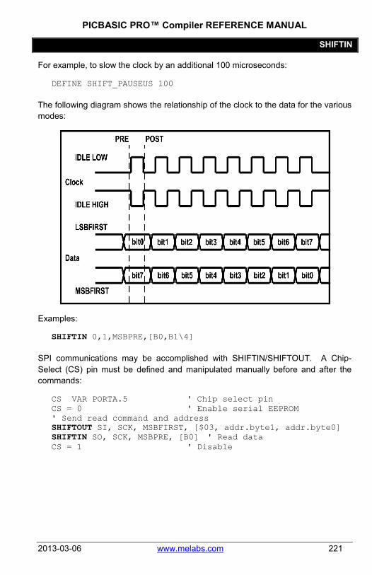
PICBASIC PRO™ Compiler REFERENCE MANUAL
SHIFTIN
2013-03-06 www.melabs.com 221
For example, to slow the clock by an additional 100 microseconds:
DEFINE SHIFT_PAUSEUS 100
The following diagram shows the relationship of the clock to the data for the various modes:
Examples:
SHIFTIN 0,1,MSBPRE,[B0,B1\4]
SPI communications may be accomplished with SHIFTIN/SHIFTOUT. A Chip-Select (CS) pin must be defined and manipulated manually before and after the commands:
CS VAR PORTA.5 ' Chip select pin CS = 0 ' Enable serial EEPROM ' Send read command and address SHIFTOUT SI, SCK, MSBFIRST, [$03, addr.byte1, addr.byte0] SHIFTIN SO, SCK, MSBPRE, [B0] ' Read data CS = 1 ' Disable
PICBASIC PRO™ Compiler REFERENCE MANUAL
SHIFTOUT
222 www.melabs.com 2013-03-06
5.75 SHIFTOUT SHIFTOUT DataPin, ClockPin, Mode, [Var{\Bits}...]
Synchronously shift out Var on ClockPin and DataPin. ClockPin and DataPin may be a constant, 0-15, or a variable that contains a number 0-15 (e.g. B0) or a pin name (e.g. PORTA.0).
SHIFTOUT is a software-based command and does not require that the target device have synchronous serial capability. The ClockPin and DataPin parameters may be set to any digital I/O pins, and may be different in different commands within the same program.
\Bits optionally specifies the number of bits to be shifted out. If it is not specified, 8 bits are shifted out, independent of the variable type. The Bits shifted out are always the low order bits, regardless of the Mode used, LSB or MSB. Up to 32 Bits can be shifted out of a single (long) variable. If more than 32 Bits are required, multiple variables or constants may be included between the square brackets.
The Mode names (e.g. LSBFIRST) are defined in the file MODEDEFS.BAS. To use them, add the line:
Include "modedefs.bas"
to the top of the PICBASIC PRO program. BS1DEFS.BAS and BS2DEFS.BAS already includes MODEDEFS.BAS. Do not include it again if one of these files is already included. The Mode numbers may be used without including this file. Some Modes do not have a name.
Mode Mode No. Operation
LSBFIRST 0 Shift data out lowest bit first. Clock idles low.
MSBFIRST 1 Shift data out highest bit first. Clock idles low.
4 Shift data out lowest bit first. Clock idles high.
5 Shift data out highest bit first. Clock idles high.
For Modes 0-1, the clock idles low, toggles high to clock in a bit, and then returns low. For Modes 4-5, the clock idles high, toggles low to clock in a bit, and then returns high.
The shift clock runs at about 50kHz, dependent on the oscillator. The active state is held to a minimum of 2 microseconds. A DEFINE allows the active state of the clock to be extended by an additional number of microseconds up to 65,535 (65.535 milliseconds) to slow the clock rate. The minimum additional delay is

PICBASIC PRO™ Compiler REFERENCE MANUAL
SHIFTOUT
2013-03-06 www.melabs.com 223
defined by the PAUSEUS timing. See its section for the minimum for any given oscillator. This DEFINE is not available on 12-bit core PIC MCUs.
For example, to slow the clock by an additional 100 microseconds:
DEFINE SHIFT_PAUSEUS 100
The following diagram shows the relationship of the clock to the data for the various modes:
Examples:
SHIFTOUT 0,1,MSBFIRST,[B0,B1] SHIFTOUT PORTA.1,PORTA.2,1,[wordvar\4] SHIFTOUT PORTC.1,PORTB.1,4,[$1234\16, $56]
SPI communications may be accomplished with SHIFTIN/SHIFTOUT. A Chip-Select (CS) pin must be defined and manipulated manually before and after the commands:
CS VAR PORTA.5 ' Chip select pin CS = 0 ' Enable serial EEPROM ' Send read command and address SHIFTOUT SI, SCK, MSBFIRST, [$03, addr.byte1, addr.byte0] SHIFTIN SO, SCK, MSBPRE, [B0] ' Read data CS = 1 ' Disable
PICBASIC PRO™ Compiler REFERENCE MANUAL
SLEEP
224 www.melabs.com 2013-03-06
5.76 SLEEP SLEEP Period
Place microcontroller into low power mode for Period seconds. Period is 16-bits using PBPW, so delays can be up to 65,535 seconds (just over 18 hours). For PBPL, Period is 32-bits so delays can be quite, quite long.
To achieve minimum current draw it may be necessary to turn off other peripherals on the device, such as the ADC, before executing the SLEEP command. See the Microchip data sheet for the specific device for information about these register settings.
SLEEP wakes up periodically using the Watchdog Timer to check to see if its time is up. If time is not up, it goes back to sleep until the next Watchdog Timer timeout and checks again. If a program is sleeping and waiting for some other event to wake it up, such as an interrupt, it may be more desirable to use the NAP command as it does not operate in SLEEP's looped fashion.
SLEEP uses the Watchdog Timer so it is independent of the actual oscillator frequency. The granularity is about 2 seconds and may vary based on device specifics and temperature. This variance is unlike the BASIC Stamp. The change was necessitated because when the PIC MCU executes a Watchdog Timer reset, it resets many of the internal registers to predefined values. These values may differ greatly from what your program may expect. By running the SLEEP command uncalibrated, this issue is sidestepped.
SLEEP 60 ' Sleep for about 1 minute

PICBASIC PRO™ Compiler REFERENCE MANUAL
SOUND
2013-03-06 www.melabs.com 225
5.77 SOUND SOUND Pin, [Note, Duration{,Note, Duration...}]
Generates tone and/or white noise on the specified Pin. Pin is automatically made an output. Pin may be a constant, 0 - 15, or a variable that contains a number 0 - 15 (e.g. B0) or a pin name (e.g. PORTA.0).
Note 0 is silence. Notes 1-127 are tones. Notes 128-255 are white noise. Tones and white noises are in ascending order (i.e. 1 and 128 are the lowest frequencies, 127 and 255 are the highest). Note 1 is about 78.74Hz and Note 127 is about 10,000Hz.
Duration is 0-255 and determines how long the Note is played in about 12 millisecond increments. Note and Duration needn't be constants.
SOUND outputs TTL-level square waves. Thanks to the excellent I/O characteristics of the PIC MCU, a speaker can be driven through a capacitor. The value of the capacitor should be determined based on the frequencies of interest and the speaker load. Piezo speakers can be driven directly.
SOUND PORTB.7,[100,10,50,10] ' Send 2 sounds consecutively toPin7

PICBASIC PRO™ Compiler REFERENCE MANUAL
STOP
226 www.melabs.com 2013-03-06
5.78 STOP STOP
Stop program execution by executing an endless loop. This does not place the microcontroller into low power mode. The microcontroller is still working as hard as ever. It is just not getting much done.
STOP ' Stop program dead in its tracks

PICBASIC PRO™ Compiler REFERENCE MANUAL
SWAP
2013-03-06 www.melabs.com 227
5.79 SWAP SWAP Variable, Variable
Exchange the values between 2 variables. Usually, it is a tedious process to swap the value of 2 variables. SWAP does it in one statement without using any intermediate variables. It can be used with bit, byte, word and long variables. Array variables with a variable index may not be used in SWAP although array variables with a constant index are allowed.
Temp = B0 B0 = B1 ' Old way B1 = temp SWAP B0, B1 ' One line way

PICBASIC PRO™ Compiler REFERENCE MANUAL
TOGGLE
228 www.melabs.com 2013-03-06
5.80 TOGGLE TOGGLE Pin
Invert the state of the specified Pin. Pin is automatically made an output. Pin may be a constant, 0 - 15, or a variable that contains a number 0 - 15 (e.g. B0) or a pin name (e.g. PORTA.0).
Low 0 ' Start Pin0 as low TOGGLE 0 ' Change state of Pin0 to high
Since this command automatically sets the data-direction of the pin it acts on, the Pin parameter should only be a PORT or GPIO register (or an alias to a PORT or GPIO register). If the command is directed to act upon a LAT output or a bit within a variable or SFR, it will attempt to set a data-direction register that doesn't exist. The result may be unexpected behavior since a bit is changed in a seemingly random memory location. This can be very difficult to debug.
PICBASIC PRO™ Compiler REFERENCE MANUAL
USBIN
2013-03-06 www.melabs.com 229
5.81 USBIN USBIN Endpoint, Buffer, Countvar, Label
Get any available USB data for the Endpoint and place it in the Buffer. Buffer must be a byte array of suitable length to contain the data. Countvar should be set to the size of the buffer before USBIN is executed. It will contain the number of bytes transferred to the buffer. Label will be jumped to if no data is available.
This instruction may only be used with a PIC MCU that has an on-chip USB port such as the low-speed PIC16C745 and 765, and the full-speed PIC18F2550 and 4550.
The USB and USB18 subdirectories contain the modified Microchip USB libraries as well as example programs. USB programs require several additional files to operate (which are in the USB or USB18 subdirectory), some of which will require modification for your particular application. See the text file in the subdirectory for more information on the USB commands. The USB subdirectory is for the low-speed PIC16C devices and the USB18 subdirectory is for the full-speed PIC18F devices.
USB communications is much more complicated than synchronous (SHIFTIN and SHIFTOUT) and asynchronous (SERIN, SEROUT and so forth) communications. There is much more to know about USB operation that can possibly be described here. The USB information on the Microchip web site needs to be studied. Also, the book "USB Complete" by Jan Axelson may be helpful.
cnt = 8 USBIN 1, buffer, cnt, idleloop
PICBASIC PRO™ Compiler REFERENCE MANUAL
USBINIT
230 www.melabs.com 2013-03-06
5.82 USBINIT USBINIT
USBINIT needs to be one of the first statements in a program that uses USB communications. It will initialize the USB portion of the PIC MCU.
This instruction may only be used with a PIC MCU that has an on-chip USB port such as the low-speed PIC16C745 and 765, and the full-speed PIC18F2550 and 4550.
The USB and USB18 subdirectories contain the modified Microchip USB libraries as well as example programs. USB programs require several additional files to operate (which are in the USB or USB18 subdirectory), some of which will require modification for your particular application. See the text file in the subdirectory for more information on the USB commands. The USB subdirectory is for the low-speed PIC16C devices and the USB18 subdirectory is for the full-speed PIC18F devices.
USB communications is much more complicated than synchronous (SHIFTIN and SHIFTOUT) and asynchronous (SERIN, SEROUT and so forth) communications. There is much more to know about USB operation that can possibly be described here. The USB information on the Microchip web site needs to be studied. Also, the book "USB Complete" by Jan Axelson may be helpful.
USBINIT

PICBASIC PRO™ Compiler REFERENCE MANUAL
USBOUT
2013-03-06 www.melabs.com 231
5.83 USBOUT USBOUT Endpoint, Buffer, Count, Label
Take Count number of bytes from the array variable Buffer and send them to the USB Endpoint. If the USB buffer does not have room for the data because of a pending transmission, no data will be transferred and program execution will continue at Label.
This instruction may only be used with a PIC MCU that has an on-chip USB port such as the low-speed PIC16C745 and 765, and the full-speed PIC18F2550 and 4550.
The USB and USB18 subdirectories contain the modified Microchip USB libraries as well as example programs. USB programs require several additional files to operate (which are in the USB or USB18 subdirectory), some of which will require modification for your particular application. See the text file in the subdirectory for more information on the USB commands. The USB subdirectory is for the low-speed PIC16C devices and the USB18 subdirectory is for the full-speed PIC18F devices.
USB communications is much more complicated than synchronous (SHIFTIN and SHIFTOUT) and asynchronous (SERIN, SEROUT and so forth) communications. There is much more to know about USB operation that can possibly be described here. The USB information on the Microchip web site needs to be studied. Also, the book "USB Complete" by Jan Axelson may be helpful.
USBOUT 1, buffer, 4, outloop

PICBASIC PRO™ Compiler REFERENCE MANUAL
USBSERVICE
232 www.melabs.com 2013-03-06
5.84 USBSERVICE USBSERVICE
USBSERVICE needs to be executed repeatedly in the program. Since the USB code provided for the full-speed PIC18F devices is polled rather than interrupt driven, USBSERVICE needs to be executed at least every 10ms throughout the program. If it is not, the device may drop off the USB bus.
When interacting with Windows, at the beginning of the program after USBINIT, it is required that USBSERVICE be polled at about 250 us per loop. Even 1ms may be too slow. It can take up to 5 seconds to complete the initial interaction to get to the state of usb_device_state == CONFIGURED_STATE, but many times it will complete much more quickly. Then, you have to continue to poll USBSERVICE to complete the passing of the HID data to the host. Doing it for another 0.5 seconds seems to be adequate.
This instruction may only be used with a PIC MCU that has an on-chip full-speed USB port such as the PIC18F2550 and 4550.
The USB18 subdirectory contains the modified Microchip USB libraries as well as example programs. USB programs require several additional files to operate (which are in the USB18 subdirectory), some of which will require modification for your particular application. See the text file in the subdirectory for more information on the USB commands.
USB communications is much more complicated than synchronous (SHIFTIN and SHIFTOUT) and asynchronous (SERIN, SEROUT and so forth) communications. There is much more to know about USB operation that can possibly be described here. The USB information on the Microchip web site needs to be studied. Also, the book "USB Complete" by Jan Axelson may be helpful.
USBSERVICE

PICBASIC PRO™ Compiler REFERENCE MANUAL
WHILE..WEND
2013-03-06 www.melabs.com 233
5.85 WHILE..WEND WHILE Condition Statement... WEND
This command has been deprecated. Use DO..LOOP instead.
Repeatedly execute Statements WHILE Condition is true. When the Condition is no longer true, execution continues at the statement following the WEND. Condition may be any comparison expression.
i = 1 WHILE i <= 10
SEROUT 0,N2400,["No:",#i,13,10] i = i + 1
WEND

PICBASIC PRO™ Compiler REFERENCE MANUAL
WRITE
234 www.melabs.com 2013-03-06
5.86 WRITE WRITE Address,{WORD}{LONG}Value {,Value...}
Write byte, word or long (if PBPL used) Values to the on-chip EEPROM at the specified Address. This instruction may only be used with a PIC MCU that has on-chip EEPROM (Data Space).
WRITE is used to set the values of the on-chip EEPROM at runtime. To set the values of the on-chip EEPROM at device programming-time, use the DATA or EEPROM statement.
Each WRITE is self-timed and may take up to 10 milliseconds to execute on a PIC MCU.
For 12-bit core devices that support flash data memory, like the PIC12F519 and PIC16F526, ERASECODE must be used to erase the rows of memory before it can be rewritten using WRITE. See ERASECODE for more information.
If interrupts are used in a program, they must be turned off (masked, not DISABLEd) before executing a WRITE, and turned back on (if desired) after the WRITE instruction is complete. An interrupt occurring during a WRITE may cause it to fail. The following DEFINE turns interrupts off and then back on within a WRITE command. Do not use this DEFINE if interrupts are not used in the program.
DEFINE WRITE_INT 1
WRITE will not work on devices with on-chip I2C interfaced serial EEPROM like the PIC12CE67x and PIC16CE62x parts. Use the I2CWRITE instruction instead.
WRITE 5, B0 ' Send value in B0 to EEPROM location 5
WRITE 0, Word W1, Word W2, B6 WRITE 10, Long L0 ' PBPL only

PICBASIC PRO™ Compiler REFERENCE MANUAL
WRITECODE
2013-03-06 www.melabs.com 235
5.87 WRITECODE WRITECODE Address, Value
Write Value to the code space at location Address.
Some PIC16F and PIC18F devices allow program code to be written at run-time. While writing self-modifying code can be a dangerous technique, it does allow non-volatile data storage in devices that do not have on-chip EEPROM or when more than the 64 - 1024 bytes that on-chip EEPROM provides is not enough. However, one must be very careful not to write over active program memory.
Note that code space (program memory) has a finite lifespan estimated in number of writes. It is shorter lived than other types of memory like RAM and EEPROM (data memory). WRITECODE, if used, should be used sparingly so as not to "wear out" the memory in the device.
The listing file may be examined to determine program addresses.
For PIC16F devices, 14-bit-sized data can be written to word code space Addresses.
For PIC18F devices, byte or word-sized data can be written to byte (rather than word) code space Addresses. The variable size of Value determines the number of bytes written. Bit- and byte-sized variables write 1 byte. Word- and long-size variables write 2 bytes to 2 sequential locations.
For block accessed devices, like the PIC16F877a and PIC18F452, a complete block must be written at once. This write block size is different for different PIC MCUs
Note that block writes are not actually executed until the end location of the block is written to. If you write to random addresses within a block and neglect to write to the end location, the previously buffered data will not be written and will be lost.
See the Microchip data sheet for the particular device for information on the block size. Start addresses for will always be exact multiples of the block size, end addresses are calculated as start address + (block size – 1).
Additionally, some flash PIC MCUs, like the PIC18F series, require a portion of the code space to be erased before it can be rewritten with WRITECODE. See the section on ERASECODE for more information.
If interrupts are used in a program, they must be turned off (masked, not DISABLEd) before executing a WRITECODE, and turned back on (if desired) after the WRITECODE instruction is complete. An interrupt occurring during a

PICBASIC PRO™ Compiler REFERENCE MANUAL
WRITECODE
236 www.melabs.com 2013-03-06
WRITECODE may cause it to fail. The following DEFINE turns interrupts off and then back on within a WRITECODE command. Do not use this DEFINE if interrupts are not used in the program.
DEFINE WRITE_INT 1
Flash program writes must be enabled in the configuration for the PIC MCU at device programming time for WRITECODE to be able to write.
WRITECODE $100,w ' Send value in W to code space location $100

PICBASIC PRO™ Compiler REFERENCE MANUAL
XIN
2013-03-06 www.melabs.com 237
5.88 XIN XIN DataPin, ZeroPin,{Timeout, Label,}[Var{,...}]
Receive X-10 data and store the House Code and Key Code in Var.
XIN is used to receive information from X-10 devices that can send such information. X-10 modules are available from a wide variety of sources under several trade names. An interface is required to connect the microcontroller to the AC power line. The TW-523 for two-way X-10 communications is required by XIN. This device contains the power line interface and isolates the microcontroller from the AC line. Since the X10 format is patented, this interface also covers the license fees.
DataPin is automatically made an input to receive data from the X-10 interface. ZeroPin is automatically made an input to receive the zero crossing timing from the X-10 interface. Both pins should be pulled up to 5 volts with 4.7K resistors. DataPin and ZeroPin may be a constant, 0-15, or a variable that contains a number 0-15 (e.g. B0) or a pin name (e.g. PORTA.0).
An optional Timeout and Label may be included to allow the program to continue if X-10 data is not received within a certain amount of time. Timeout is specified in AC power line half-cycles (approximately 8.33 milliseconds).
XIN only processes data at each zero crossing of the AC power line as received on ZeroPin. If there are no transitions on this line, XIN will effectively wait forever.
If Var is word-sized, each House Code received is stored in the upper byte of the word. Each received Key Code is stored in the lower byte of the word. If Var is a byte, only the Key Code is stored.
The House Code is a number between 0 and 15 that corresponds to the House Code set on the X-10 module A through P.
The Key Code can be either the number of a specific X-10 module or the function that is to be performed by a module. In normal practice, first a command specifying the X-10 module number is sent, followed by a command specifying the function desired. Some functions operate on all modules at once so the module number is unnecessary. Hopefully, later examples will clarify things. Key Code numbers 0-15 correspond to module numbers 1-16.
These Key Code numbers are different from the actual numbers sent and received by the X10 modules. This difference is to match the Key Codes in the BS2. To remove this Stamp translation, the following DEFINE may be used:

PICBASIC PRO™ Compiler REFERENCE MANUAL
XIN
238 www.melabs.com 2013-03-06
DEFINE XINXLAT_OFF 1
XIN is not supported on 12-bit core PIC MCUs due to RAM and stack constraints.
XOUT below lists the functions as well as the wiring information.
housekey Var Word mainloop: ' Get X-10 data
XIN PORTA.2,PORTA.0,[housekey] ' Display X-10 data on LCD LCDOUT $fe,1,"House=",#housekey.byte1,_ "Key=",#housekey.byte0
Goto mainloop ' Do it forever ' Check for X-10 data, go to nodata if none XIN PORTA.2,PORTA.0,1,nodata,[housekey]

PICBASIC PRO™ Compiler REFERENCE MANUAL
XOUT
2013-03-06 www.melabs.com 239
5.89 XOUT XOUT DataPin, ZeroPin, [HouseCode\KeyCode{\Repeat}{,...}]
Send HouseCode followed by KeyCode, Repeat number of times in X10 format. If the optional Repeat is left off, 2 times (the minimum) is assumed. Repeat is usually reserved for use with the Bright and Dim commands.
XOUT is used to send control information to X-10 modules. These modules are available from a wide variety of sources under several trade names. An interface is required to connect the microcontroller to the AC power line. Either the PL-513 for send only, or the TW-523 for two-way X-10 communications are required. These devices contain the power line interface and isolate the microcontroller from the AC line. Since the X-10 format is patented, these interfaces also cover the license fees.
DataPin is automatically made an output to send data to the X-10 interface. ZeroPin is automatically made an input to receive the zero crossing timing from the X-10 interface. It should be pulled up to 5 volts with a 4.7K resistor. DataPin and ZeroPin may be a constant, 0-15, or a variable that contains a number 0-15 (e.g. B0) or a pin name (e.g. PORTA.0).
XOUT only processes data at each zero crossing of the AC power line as received on ZeroPin. If there are no transitions on this line, XOUT will effectively wait forever.
HouseCode is a number between 0 and 15 that corresponds to the House Code set on the X-10 module A through P. The proper HouseCode must be sent as part of each command.
The KeyCode can be either the number of a specific X-10 module or the function that is to be performed by a module. In normal practice, first a command specifying the X-10 module number is sent, followed by a command specifying the function desired. Some functions operate on all modules at once so the module number is unnecessary. Hopefully, later examples will clarify things. KeyCode numbers 0-15 correspond to module numbers 1-16.
The KeyCode (function) names (e.g. unitOn) are defined in the file MODEDEFS.BAS. To use them, add the line:
Include "modedefs.bas"
to the top of the PICBASIC PRO program. BS1DEFS.BAS and BS2DEFS.BAS already includes MODEDEFS.BAS. Do not include it again if one of these files is already included. The KeyCode numbers may be used without including this file.

PICBASIC PRO™ Compiler REFERENCE MANUAL
XOUT
240 www.melabs.com 2013-03-06
KeyCode KeyCode No. Operation
unitOn %10010 Turn module on unitOff %11010 Turn module off unitsOff %11100 Turn all modules off lightsOn %10100 Turn all light modules
on lightsOff %10000 Turn all light modules
off bright %10110 Brighten light module dim %11110 Dim light module
These Keycode numbers are different from the actual numbers sent and received by the X10 modules. This difference is to match the Keycodes in the BS2. To remove this Stamp translation, the following DEFINE may be used:
DEFINE XOUTXLAT_OFF 1
XOUT is not supported on 12-bit core PIC MCUs due to RAM and stack constraints.
Wiring to the X-10 interfaces requires 4 connections. Output from the X10 interface (zero crossing and receive data) are open-collector and require a pull up resistor of around 4.7K to 5 volts. Wiring tables for each interface is shown below:
PL-513 Wiring
Wire No. Wire Color Connection
1 Black Zero crossing output 2 Red Zero crossing common 3 Green X-10 transmit common 4 Yellow X-10 transmit input

PICBASIC PRO™ Compiler REFERENCE MANUAL
XOUT
2013-03-06 www.melabs.com 241
TW-523 Wiring
Wire No. Wire Color Connection
1 Black Zero crossing output
2 Red Common
3 Green X-10 receive output
4 Yellow X-10 transmit input
House VAR BYTE Unit VAR BYTE Include "modedefs.bas" house = 0 ' Set house to 0 (A) unit = 8 ' Set unit to 8 (9) ' Turn on unit 8 in house 0 XOUT PORTA.1,PORTA.0,[house\unit, house\unitOn] ' Turn off all the lights in house 0 XOUT PORTA.1,PORTA.0,[house\lightsOff] ' Blink light 0 on and off every 10 seconds XOUT PORTA.1,PORTA.0,[house\0] loop: XOUT PORTA.1,PORTA.0,[house\unitOn] Pause 10000 ' Wait 10 seconds XOUT PORTA.1,PORTA.0,[house\unitOff] Pause 10000 ' Wait 10 seconds Goto loop

PICBASIC PRO™ Compiler REFERENCE MANUAL
Interrupts
242 www.melabs.com 2013-03-06
Chapter 6: Interrupts

PICBASIC PRO™ Compiler REFERENCE MANUAL
Interrupts
2013-03-06 www.melabs.com 243
The term Interrupt refers to the practice of suspending execution of program code when a predetermined event takes place. The main program is "frozen", while program execution is routed to an Interrupt Service Routine (ISR) that performs some task in response to the event that has been detected. When the ISR completes its duties, program execution is returned to the interrupted process, which should continue undisturbed.
Interrupts can be triggered by external events like a button press or a sensor input. They can also be triggered by an internal process like a timer overflowing or a conversion being completed.
When planning a design using interrupts, thought should be given to which functions should be performed in the interrupt service routine and which should be the responsibility of the main program. In most cases, it is desirable to keep the interrupt routine as short as possible. If the execution time of the ISR is longer than one iteration of the main program loop, you may want to rethink your design. Sometimes the project will benefit from a reversal of duties, where the functions of the main program are moved to the ISR and vice versa.
The details of available interrupts differ from on device to another. You must consult the datasheet for the specific device you are using. In general, you will find the following types of interrupt triggers for various chips:
• Change to the state of an input pin • Change to the state of an input port • Overflow of an internal timer register • Overflow of a counter register • Completion of an analog conversion • Change in a comparator result • Reception of serial data • Completion of a serial data send • Completion of a timed event capture • Various failures and error conditions
Interrupts are a necessity for many embedded designs, but it's best not to use them without real need. Interrupts will always add a layer of complexity to your program that can make debugging more difficult. Interrupts should not be feared, but you should accept that a bit of effort may be required to make them work as desired.
Note that the interrupt flag bits (the bits that indicate when a particular interrupt has occurred) continue to function even when interrupts are disabled. This is a valuable resource, as you can check and clear the flag bits manually in your program. Your program can test for an interrupt event, without actually enabling interrupts.
PICBASIC PRO™ Compiler REFERENCE MANUAL
Interrupts
244 www.melabs.com 2013-03-06
6.1 Interrupts Using ON INTERRUPT PBP's ON INTERRUPT offers a simplified system of handling interrupts. It acts as a layer of automatic checking for the hardware interrupt indicators and directs your program execution to an interrupt-handling subroutine (written in BASIC) that you specify. ON INTERRUPT offers an easy way to deal with interrupts, but with a possible delay (latency) in its response to the interrupt trigger. More on latency can be found later in this section.
This method involves the use of the following commands and directives. They are listed here with reference to the section in this manual where descriptions can be found.
4.1 DISABLE 4.3 DISABLE INTERRUPT 4.4 ENABLE 4.6 ENABLE INTERRUPT 4.8 ON INTERRUPT 5.66 RESUME Details about the workings of the actual interrupt triggers, their control registers, and their flag bits can be found in the Microchip datasheet for the specific MCU that you are compiling for.
6.1.1 In Practice
To use the ON INTERRUPT method, the following steps must be performed:
• Place the ON INTERRUPT directive • Enable the GIE bit and the appropriate Interrupt Enable bit(s). • Place the interrupt handler routine in a section of program where interrupts
are disabled, and within it: o Execute code o Clear interrupt flags o Finish with a RESUME command
A short example follows that uses the "external interrupt" to toggle the state of an LED, while the main program flashes a different LED.
This example will also demonstrate the latency that is associated with ON INTERRUPT. If the interrupt trigger occurs during execution of one of the "PAUSE 500" statements, nothing will happen until the command finishes. This could result in up to 500mS delay before seeing the effect of the interrupt trigger.

PICBASIC PRO™ Compiler REFERENCE MANUAL
Interrupts
2013-03-06 www.melabs.com 245
ON INTERRUPT GOTO myint ' Interrupt handler is myint, enable interrupt-checking for lines below this point.
INTCON = %10010000 ' Enable GIE and RB0 interrupt mainloop: HIGH led1 ' LED1 on PAUSE 500 ' Wait a half second LOW led1 ' LED2 off PAUSE 500 ' Wait a half second GOTO mainloop ' Loop forever DISABLE ' Disable interrupt-checking for
all routines placed below this line.
myint: TOGGLE led2 ' Toggle LED2 when interrupted INTCON.1 = 0 ' Clear interrupt flag RESUME ' Return to main program
If you wish to handle multiple interrupt triggers, each with separate handling routines, you should check the interrupt flags when entering the interrupt handler. Execute the appropriate section of code to handle the trigger that brought program execution to the handler routine.
Notice in the above example that ON INTERRUPT is immediately followed by the setting of the INTCON register and the GIE bit, before any code in the interrupt-enabled section of code is executed. Because the interrupt-checking code will perceive an interrupt event if GIE is clear, care should be taken to only enter the interrupt-enabled section of code (the code under the ON INTERRUPT directive) when GIE is set.
If, in the above example, you used a GOTO placed above the ON INTERRUPT directive to jump directly to the "mainloop" label without first setting the INTCON register, a false interrupt would be perceived and the program would immediately jump to the interrupt handler routine.
You can avoid this by placing ON INTERRUPT and the INTCON setting earlier in the program, so that interrupts are enabled before any jumps occur.
You can also write a safeguard in the first lines of the interrupt handler that checks the interrupt enable and flag bits to make sure that interrupt is real. Checking only the flag bit is not enough in this situation because flags are set upon their associated events, even when the interrupt is not enabled.

PICBASIC PRO™ Compiler REFERENCE MANUAL
Interrupts
246 www.melabs.com 2013-03-06
Here is an example that would perform this safety check in the "myint" routine in the above example:
myint: ' Execute only when enable and flag bits are both set. ' If either bit is clear (low), abort and return. IF (INTCON.5=0) OR (INTCON.1=0) THEN RESUME TOGGLE led2 ' Toggle LED2 when interrupted INTCON.1 = 0 ' Clear interrupt flag RESUME ' Return to main program
6.1.2 How ON INTERRUPT Works
The ON INTERRUPT method is not quite the same as an Assembly Language interrupt method. When ON INTERRUPT is used, a short interrupt handler is placed at location 4 in the PIC MCU. This interrupt handler is simply a Return. What this does, is send the program back to what it was doing before the interrupt occurred. It doesn’t require any processor context saving.
What it doesn’t do, is re-enable Global Interrupts as happens using an Assembly Language RETFIE instruction. In this system, the Global Interrupts Enable bit (GIE) serves as a flag that can be checked during program execution. If GIE is disabled, it is known that an interrupt trigger occurred.
In sections of code where the ON INTERRUPT layer has been enabled, a call to a short subroutine is placed before each statement in the PICBASIC PRO. This short subroutine checks the state of the Global Interrupt Enable bit. If it is off, an interrupt is pending, so it vectors to the user's interrupt handler. If it is still set, the program continues with the next BASIC statement, after which, the GIE bit is checked again and so forth.
Using ON INTERRUPT, PBP simply flags the interrupt event and immediately goes back to what it was doing. It does not immediately vector to your interrupt handler. Since the GIE bit is only checked before each PBP command begins, there could be considerable delay (latency) before the interrupt is handled. Interrupts that happen during execution of a PBP command are essentially ignored until the command finishes. Commands with long execution times may result in long latency in interrupt handling.
As an example, let's say that the PICBASIC PRO program just started execution of a Pause 10000 when an interrupt occurs. PBP will flag the interrupt and continue with the PAUSE. It could be up to 10 seconds later before the interrupt handler is

PICBASIC PRO™ Compiler REFERENCE MANUAL
Interrupts
2013-03-06 www.melabs.com 247
executed. If it is buffering characters from a serial port, many characters will be missed.
To minimize the problem, use only statements that don’t take very long to execute. For example, instead of Pause 10000, use Pause 1 in a long FOR..NEXT loop. This will allow PBP to complete each statement more quickly and handle any pending interrupts.
If interrupt processing needs to occur more quickly than can be provided by ON INTERRUPT, interrupts in Assembly Language should be used.
When the RESUME statement is encountered at the end of the BASIC interrupt handler, it sets the GIE bit to re-enable interrupts and returns to where the program was before the interrupt occurred. If RESUME is given a label to jump to, execution will continue at that location instead. All previous return addresses will be lost in this case.
DISABLE stops PBP from inserting the call to the interrupt checker after each statement. This allows sections of code to execute without the possibility of being interrupted. ENABLE allows the insertion to continue.
A DISABLE should be placed before the interrupt handler so that it will not keep getting restarted by checking the GIE bit.
If it is desired to turn off interrupts for some reason after ON INTERRUPT is encountered, you must not turn off the GIE bit. Turning off this bit tells PBP that an interrupt has happened and it will execute the interrupt handler forever. Instead, clear the individual interrupt enable bit(s). In the example above, you could write:
INTCON.5 = 0 ' Disable external interrupt (See the datasheet)
Note that the enable bit associated with the interrupt that you are using may be in a different register than INTCON. See the datasheet's section on Interrupts to gain understanding on the working of the interrupt that you wish to use.

PICBASIC PRO™ Compiler REFERENCE MANUAL
Interrupts
248 www.melabs.com 2013-03-06
6.2 Interrupts Using Assembly Language Assembly Language Interrupt Handlers are the most responsive way to handle interrupt events. Latency with this method is virtually the same as with pure Assembly programs. Using this method, interrupts will suspend program execution even during execution of PBP commands.
As you might guess, using Assembly Language is a bit more involved than a purely BASIC program. We can't offer a full Assembly Language tutorial in this manual, but we'll try to give you the fundamental concerns for interrupt handlers. There is a bit more information in section 7.1 In-Line Assembly Language.
6.2.1 Checklist
The requirements for setting up an Assembly interrupt handler are:
• Use a DEFINE to specify the Assembly label that begins the routine • Declare special variables for saving context (when appropriate) • Set registers to enable the desired interrupts • Place the handler routine at the beginning of your program as in-line
Assembly and within it: o Determine whether context saving code is required and include it
appropriately o Execute Assembly code to handle the event o Clear interrupt flags o Restore context from variables o Return to main program with RETFIE instruction

PICBASIC PRO™ Compiler REFERENCE MANUAL
Interrupts
2013-03-06 www.melabs.com 249
6.2.2 DEFINEs
PBP offers a DEFINE to specify the name of the interrupt service routine label. The label refers to the Assembly Language label that marks the beginning of your service routine.
DEFINE INTHAND Label
For devices with multiple priority interrupts, PBP offers a single additional DEFINE that allows you to specify a second label for a second service routine. This routine will be used for low-priority interrupts.
DEFINE INTLHAND Label
6.2.3 Enabling Interrupts
Interrupts should be enabled without concern for PBP. In other words, enable interrupts as appropriate for a pure Assembly Language program.
This will most often consist of at least two bit-settings, one to enable the Global Interrupt Enable (GIE) and one to enable the specific interrupt that you desire to use. If the interrupt is a "peripheral" interrupt, there is an additional Peripheral Interrupt Enable bit (PIE) that must be set.
' For PIC18, enable the USART-receive interrupt: INTCON = %11000000 ' Enable Global and Peripheral
interrupts PIE1.5 = 1 ' Enable USART receive interrupt
To disable and enable interrupts during program execution, the easiest method is to manipulate only the Global Interrupt Enable (GIE) bit:
INTCON.7 = 0 ' Disable interrupts INTCON.7 = 1 ' Enable interrupts
Note that this is in direct conflict with the ON INTERRUPT method, for which you should never manipulate the GIE directly.
6.2.4 Placement of the Assembly Language Routine
It is customary to place the interrupt-handler code at the beginning of the executable program, after declaring variables, constants and aliases. There are various reasons for this, but an exhaustive explanation for all the device types

PICBASIC PRO™ Compiler REFERENCE MANUAL
Interrupts
250 www.melabs.com 2013-03-06
would contain a lot of unnecessary information. Suffice to say that it lessens the probability of code-page issues with some devices that are vulnerable to such things.
Since you don't want your interrupt handler to execute upon power-up or reset, precede the interrupt handler with a PBP GOTO to jump over it.
GOTO main ' Jump over interrupt handler ASM myint ; Start handler code ; code here RETFIE ; Return to main program ENDASM main: ' Start PBP program
6.2.5 Declaring Special Variables to Save Context
In order for program execution to return to the main program after handling an interrupt, there are some key register values that must be saved when leaving the main program and restored when returning. The data made up of these key registers is called the "context". Saving and restoring context allows the program to resume reliably after an interrupt event.
In the following sections, details will be found for each type of PIC microcontroller.
6.2.6 Access to PBP Variables from the Interrupt Handler
We've already touched on bank selection as an issue, not just in interrupt handlers, but in in-line Assembly Language overall. The thing to remember is that, through one method or another, the procedures listed here will always result in a BANK0 selection when your interrupt handler begins to execute.
This provides a very simple solution for accessing variables that have been declared in your PBP code from your interrupt handler. If you declare the variables in BANK0, they will automatically be accessible from your Assembly code, without any bank manipulation.
tick VAR BYTE BANK0 ' Declare tick variable in BANK0
If the SYSTEM keyword is not used in the variable declaration, PBP will create the variable in Assembly with a prepended underscore character. "tick" will become

PICBASIC PRO™ Compiler REFERENCE MANUAL
Interrupts
2013-03-06 www.melabs.com 251
"_tick" when translated to Assembly. Therefore, if the variable is declared as above, you can increment it in your interrupt handler with the following.
incf _tick, F ; Increment tick variable
6.2.7 Time-Sensitive PBP Commands
When using an Assembly Language interrupt handler, you must remain aware that the execution of any PBP command in your program could be interrupted. Some PBP commands are time-critical. A software-based serial command must track precise baud timing in order to function. A PULSIN command must have a precise timebase to accurately measure a pulse.
In commands such as these, you should disable interrupts before the command begins and enable the interrupts after the command finishes.
INTCON.7 = 0 PULSIN PORTB.0, pulse_val INTCON.7 = 1
PICBASIC PRO™ Compiler REFERENCE MANUAL
Interrupts
252 www.melabs.com 2013-03-06
6.3 Assembly Interrupts for PIC18 Devices
6.3.1 Interrupt Priorities
The PIC18 devices offer the capability of assigning two levels of priority to specific interrupt types. By default, low-priority interrupts are disabled and all interrupts are handled as high-priority. The use of low-priority interrupts represents an additional level of complexity. Make sure the practice is actually needed before enabling it.
In order to use low-priority interrupts, you must first enable them (in the BASIC portion of your program):
RCON.7 = 1 ' Enable interrupt priorities
To assign which priority is used for each interrupt source, you use the IPR bits. Each bit in the IPR registers controls the priority for ONE interrupt source. Setting the bit makes it a High Priority and clearing the bit makes it Low Priority. To figure out which of the IPR bits to use, you must look them up in the datasheet.
IPR bits always default to High Priority, so you only need to change them for Low Priority if desired.
IPR1.5 = 0 ' Set USART receive interrupt to LOW priority
Under normal operation, INTCON.6 is the Peripheral Interrupt Enable bit (PEIE). When using low-priority interrupts, INTCON.6 becomes Low priority Global Interrupt Enable bit (GIEL). INTCON.7 then becomes the High Priority Global Interrupt Enable bit (GIEH)
GIEH enables all unmasked high-priority interrupts and GIEL enables all unmasked low priority interrupts. "unmasked" simply means that the individual Enable bit for that interrupt source is set to the enabled state. For example, the PIE1.5 bit (RCIE) enables the USART Receive interrupt. If that bit is 1 then the USART Receive interrupt is considered "unmasked".
Peripheral interrupts are always enabled since there is no longer a PEIE bit, but the individual peripheral interrupts must still be enabled to generate interrupts for those peripherals.
It's important to remember that a Low Priority interrupt can itself be interrupted by a High Priority interrupt. This can change expected timings or overwrite values if both routines use the same variables.

PICBASIC PRO™ Compiler REFERENCE MANUAL
Interrupts
2013-03-06 www.melabs.com 253
6.3.2 Saving and Restoring Context
If only high-priority interrupts are used on a PIC18 device, explicit save/restore methods are not usually required. The critical SFR values (WREG, STATUS, and BSR) are automatically saved in shadow registers, and the "retfie FAST" return method automatically restores the values. Other SFRs like the FSR registers, PCLATH:U, and PRODL:H should be saved and restored if your interrupt service routine changes them.
For high-priority interrupts, the handler code can be very simple:
ASM highP_label ; Label begins the routine clrf BSR ; set Bank to 0 ; your assembly code goes here retfie FAST ; Restore context and return ENDASM
Low-priority interrupts may be interrupted by the occurrence of a high-priority interrupt. For this reason, explicit context save and restore is necessary in low-priority interrupt handler. This requires additional variables to be declared in the PBP program. Declare them as follows:
wsave VAR BYTE BANKA SYSTEM ssave VAR BYTE SYSTEM bsave VAR BYTE SYSTEM
The low-priority interrupt handler should save and restore context of critical SFRs WREG, STATUS, and BSR. Other SFRs like the FSR registers, PCLATH:U, and PRODL:H should be saved and restored if your interrupt handler code changes them. An example of a low-priority interrupt handler follows.

PICBASIC PRO™ Compiler REFERENCE MANUAL
Interrupts
254 www.melabs.com 2013-03-06
ASM LowP_label ; Label begins the routine movwf wsave ; Save the Working register
(WREG) movff STATUS, ssave ; Save STATUS reg movff BSR, bsave ; Save Bank Select Register
(BSR) clrf BSR ; Set Bank to 0 ; your assembly code goes here movff ssave, STATUS ; Restore STATUS movff bsave, BSR ; Restore Bank Select Register
(BSR) movff WREG, wsave ; Restore Working register
(WREG) retfie ; Return ENDASM

PICBASIC PRO™ Compiler REFERENCE MANUAL
Interrupts
2013-03-06 www.melabs.com 255
6.3.3 Example High/Low Priority ISR Framework for PIC18
DEFINE INTHAND HP_ISR ' Assign High Priority Interrupt Service Routine label
DEFINE INTLHAND LP_ISR ' Assign Low Priority Interrupt
Service Routine label ' These variables are only required when using ' Low-Priority interrupts. wsave VAR BYTE BANKA SYSTEM ssave VAR BYTE SYSTEM bsave VAR BYTE SYSTEM GOTO main ' Jump over interrupt routines '----[High Priority interrupt service routines]--------- ASM HP_ISR clrf BSR ; Set Bank to 0 ; Your Assembly code goes here retfie FAST ENDASM '----[Low Priority interrupt service routines]---------- ASM LP_ISR ; Label begins the routine movwf wsave ; Save WREG movff STATUS, ssave ; Save STATUS movff BSR, bsave ; Save BSR clrf BSR ; Set Bank to 0 ; your assembly code goes here movff ssave, STATUS ; Restore STATUS movff bsave, BSR ; Restore BSR movff WREG, wsave ; Restore WREG retfie ; Return ENDASM main: ' Begin main program here

PICBASIC PRO™ Compiler REFERENCE MANUAL
Interrupts
256 www.melabs.com 2013-03-06
6.4 Assembly Interrupts for Enhanced 14-Bit Instruction Set
6.4.1 Saving and Restoring Context
For PIC MCUs that use the Enhanced 14-Bit instruction set (part number patterns 12F1xxx, 12LF1xxx, 16F1xxx, and 16LF1xxx), context save and restore is done automatically. You need not write any code for context save or restore.
6.4.2 Example ISR Framework for Enhanced 14-Bit
' Define interrupt handler label DEFINE INTHAND myint Goto main ' jump over interrupt handler ASM myint ; Context is saved automatically clrf BSR ; Set Bank to 0 ; Your Assembly goes code here retfie ; Return with auto context
restore ENDASM main: ' Begin main program here

PICBASIC PRO™ Compiler REFERENCE MANUAL
Interrupts
2013-03-06 www.melabs.com 257
6.5 Assembly Interrupts for 14-Bit Instruction Set
6.5.1 Declaring Special Variables to Save Context
To accommodate context save and restore in these devices, a set of special variables must be declared in the PBP program. The names of the variables are:
wsave For saving the W register ssave For saving the STATUS register psave For saving the PCLATH register
For PIC12 and PIC16 devices that do not use the Enhanced 14-bit instruction set, it is necessary to reserve space for the "wsave" variable in a special section of RAM that is accessible regardless of bank-select bit settings. The reason for this requirement is that the W register value is saved upon the interrupt event, before any bank selection change is possible. It will be stored to the memory address where wsave is allocated, but the bank selection bits may point to a different bank.
Microchip has accommodated this for the devices that share the mid-range architecture. A few addresses in RAM at the end of banks 1 and higher will access the equivalent address in BANK0. This can be utilized by placing the wsave variable in one of these "access RAM" addresses within BANK0.
To determine the actual address, you must consult the datasheet for the specific device that you are using. In the datasheet, look for the section "Data Memory Organization". In that section, there should be a table of Special Function Registers that also shows General Purpose Registers at the bottom of each bank column.
In banks numbered greater than zero, you should see a small block that is labeled with something similar to "accesses 70h-7Fh". This means that the wsave variable should be placed in somewhere in the range of addresses 70h-7Fh.
See the following example taken from the PIC16F882 datasheet. The relevant information is highlighted near the bottom.

PICBASIC PRO™ Compiler REFERENCE MANUAL
Interrupts
258 www.melabs.com 2013-03-06
With the clues gathered from the highlighted area of the table shown above, it can be determined that wsave can be placed at address 70h (written $70 in PBP):
wsave VAR BYTE $70 SYSTEM ' wsave in access RAM
Please note that the appropriate address may change from device to device. Always consult the datasheet to avoid problems.

PICBASIC PRO™ Compiler REFERENCE MANUAL
Interrupts
2013-03-06 www.melabs.com 259
The only requirement for the remaining variables "ssave" and "psave" is that they be placed in BANK0. They do not need to be at any specific address. The following variable declarations, therefore, would work for the PIC16F882:
wsave VAR BYTE $70 SYSTEM ssave VAR BYTE BANK0 SYSTEM psave VAR BYTE BANK0 SYSTEM
The "SYSTEM" keyword is used to remove the preceding underscore from the Assembly Language variable names. ("wsave" in PBP is also "wsave" in Assembly.)
6.5.2 Saving and Restoring Context
For PIC12 and PIC16 devices that do not use the Enhanced 14-bit instruction set, PBP will save context automatically if the device has more than 2K of code space (more than one code page). This is born of necessity because of the inner workings of these microcontrollers. For these devices that have 2K or less of code space, the context save needs to be done manually in your interrupt handler.
PBP inserts an Assembly Language constant for its own use that indicates the side of the code space. You can make use of this constant to conditionally insert the context-save code only when needed.
if CODE_SIZE <= 2 ; If less than 2K code space ; Save the state of critical registers (PIC12/PIC16) movwf wsave ; Save W swapf STATUS,W ; Swap STATUS to W (swap avoids
changing STATUS) clrf STATUS ; Clear STATUS movwf ssave ; Save swapped STATUS movf PCLATH,W ; Move PCLATH to W movwf psave ; Save PCLATH endif
These lines of code should be the very first thing that executes in your interrupt handler. The function of this code is to save the W register, move the value of STATUS into W with a swap to avoid affecting the value, clear STATUS to select BANK0, and finally save the appropriate values to the ssave and psave variables.
The requirement for restoring context is not dependent upon the amount of code space for these devices. Restoration of context is always required. The steps of restoring are the reverse of saving. This insures that the bank selection is manipulated in such a way as to restore the values from the same banks in which

PICBASIC PRO™ Compiler REFERENCE MANUAL
Interrupts
260 www.melabs.com 2013-03-06
they were saved. If your interrupt handler code changed the bank selection bits to something other than BANK0, make sure you change them back to BANK0 before this code is executed.
; Restore the state of critical registers (PIC12/PIC16) movf psave,W ; restore PCLATH movwf PCLATH swapf ssave,W ; restore STATUS movwf STATUS swapf wsave,F ; restore W (swap avoids
changing STATUS) swapf wsave,W retfie ; Return from interrupt
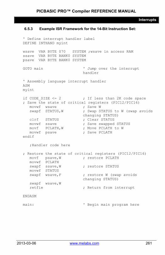
PICBASIC PRO™ Compiler REFERENCE MANUAL
Interrupts
2013-03-06 www.melabs.com 261
6.5.3 Example ISR Framework for the 14-Bit Instruction Set:
' Define interrupt handler label DEFINE INTHAND myint
wsave VAR BYTE $70 SYSTEM ;wsave in access RAM ssave VAR BYTE BANK0 SYSTEM psave VAR BYTE BANK0 SYSTEM GOTO main ' Jump over the interrupt
handler ' Assembly language interrupt handler ASM myint if CODE_SIZE <= 2 ; If less than 2K code space ; Save the state of critical registers (PIC12/PIC16) movwf wsave ; Save W swapf STATUS,W ; Swap STATUS to W (swap avoids
changing STATUS) clrf STATUS ; Clear STATUS movwf ssave ; Save swapped STATUS movf PCLATH,W ; Move PCLATH to W movwf psave ; Save PCLATH endif ;Handler code here ; Restore the state of critical registers (PIC12/PIC16) movf psave,W ; restore PCLATH movwf PCLATH swapf ssave,W ; restore STATUS movwf STATUS swapf wsave,F ; restore W (swap avoids
changing STATUS) swapf wsave,W retfie ; Return from interrupt ENDASM main: ' Begin main program here
PICBASIC PRO™ Compiler REFERENCE MANUAL
Advanced Techniques and Concepts
262 www.melabs.com 2013-03-06
Chapter 7: Advanced Techniques and Concepts

PICBASIC PRO™ Compiler REFERENCE MANUAL
Advanced Techniques and Concepts
2013-03-06 www.melabs.com 263
7.1 In-Line Assembly Language In-line Assembly Language in your PBP program is only useful in specific circumstances. The practice is most commonly used for interrupt service routines. You should be reluctant to use Assembly Language, as it adds a layer of complexity that will make it more difficult to debug your program and to port your program to different PIC MCUs.
Note that Assembly Language is NOT REQUIRED to change the internal registers in the PIC MCU. Registers may be read and written at will, in BASIC, using PBP's Direct Register Access.
Before writing in-line Assembly Code, see section 7.2 Code Pages and RAM Banks. Assembly Language syntax is not covered in this manual. See the documentation provided with the assembler application and the device datasheet for syntax and programming information.
7.1.1 Inserting Assembly Code
PBP programs may contain a single line of assembly language preceded by an "at" symbol (@), or one or more lines of assembly code preceded by the ASM keyword and ended by the ENDASM keyword. Both keywords appear on their lines alone.
@ bsf PORTA, 0 ASM bsf STATUS,RP0 bcf TRISA, 0 bcf STATUS, RP0 ENDASM
The lines of assembly are copied verbatim into the assembly output file. This allows the PBP program to use all of the facilities of the assembler. This also, however, requires that the programmer have some familiarity with the PBP libraries. PBP’s notation conventions are similar to other commercial compilers and should come as no shock to programmers experienced enough to attempt in-line Assembly.
All identifier names defined in a PBP program are similarly defined in Assembly, but with the name preceded with an underscore ( _ ). This allows access to user variables, constants, and even labeled locations, in assembly:

PICBASIC PRO™ Compiler REFERENCE MANUAL
Advanced Techniques and Concepts
264 www.melabs.com 2013-03-06
B0 Var Byte ASM movlw 10 movwf _B0 ENDASM
Thus, any name defined in assembly starting with an underscore has the possibility of conflicting with a PBP generated symbol.
PBP will not be aware of variables that you define in Assembly Language. To avoid conflict and allow PBP to effectively manage RAM allocation, variables should be declared in BASIC (even if they are only used in Assembly).
Just as underscored symbols have possible conflicts, so do symbols not starting with underscores. The problem is internal library identifiers. Luckily, most library identifiers contain a '?' or make reference to one of the working registers (such as R0). Avoiding such names should reduce problems. If you should have a name collision, the assembler will report the duplicate definitions as an error.
In BASIC code, comments may be denoted using either an apostrophe or semicolon. In Assembly Language, only a semicolon is recognized as a comment character.
' PICBASIC PRO comment ; Assembly Language comment
7.1.2 Placement of In-line Assembly
PBP statements execute in order of their appearance in the source. The organization of the code is as follows: Starting at location 0 (the reset vector) PBP inserts some startup code, followed by a jump to INIT. Next, the called-for library subroutines are stuffed in. At the end of the library is INIT, where any additional initialization is completed.
Finally, at the label MAIN, the compiled PICBASIC PRO statement code is added. The first executable line of program code appears in memory right behind the controller’s startup and library code, right after the MAIN label.
The tendency of programmers is to place their own Assembly library functions either before or after their code. There are a couple of deciding factors as to where might be the best place to insert assembly language subroutines. If the entire program fits into one code page, place your assembly routines after your PBP code. If the program is longer than one code page, it could make more sense to put the assembly language routines at the beginning of the PBP program. This

PICBASIC PRO™ Compiler REFERENCE MANUAL
Advanced Techniques and Concepts
2013-03-06 www.melabs.com 265
should ensure them of being in the first code page so that you know where to find them. This is the way assembly language interrupt routines should be handled.
If the routines are placed at the front, use a (BASIC) GOTO to jump over the code to the first executable PBP statement. If you place the routines at the end of your program, take appropriate steps to make sure the routines do not execute unintentionally.
The actual code for the assembly language routines may be included in your program or in a separate file. If a routine is used by only one particular PICBASIC PRO program, it would make sense to include the assembler code within the PBP source file. This routine can then be accessed using the CALL command.
If it is used by several different PBP programs, a separate file containing the assembly routines can simply be included at the appropriate place in the PICBASIC PRO source:
ASM Include "myasm.inc" ENDASM

PICBASIC PRO™ Compiler REFERENCE MANUAL
Advanced Techniques and Concepts
266 www.melabs.com 2013-03-06
7.2 Code Pages and RAM Banks In some PIC MCUs, the program code space is divided into "pages". In all PIC MCUs (that we have seen to date), RAM is divided into "banks".
One of the advantages of using a high-level language like PBP is that these things are managed for you. If you use PBP's native methods for writing code, declaring and accessing variables, and accessing registers, you needn't give a thought to code-page and bank settings.
There is one command that is an exception to this. PBP's BRANCH command is not capable of jumps that cross code-page boundaries. If you see a warning during assembly that indicates "crossing code-page boundary", make sure any BRANCH commands are replaced with BRANCHL.
PBP also offers the capability of inserting Assembly Language into your program. When this technique is used, consideration must be given to bank and code-page selection.
We make the assumption that users who choose to use Assembly Language know that language. Therefore, we won't go into Assembly Language techniques in this manual. This section is provided to give Assembly Language programmers the information necessary to manage code-page and bank selection in their code.
The commands and directives that provide a transition between BASIC and Assembly Language are ASM/ENDASM, @ and to some extent #CONFIG/#ENDCONFIG. They are described in other parts of this manual.
When one of these commands is used to begin a block of Assembly Language code, the code-page selection is not changed by PBP. It must be set to point to the code-page in which the first instruction of the Assembly code is placed.
The implication here is that, unless an ASM block is placed at the beginning of the program, you don't know which code-page is selected when entering the Assembly Language. The Assembly code should check and maintain code-page selection as necessary, especially when executing branch or goto instructions.
The best way to simplify this situation is to always place ASM blocks at the beginning of the code. This will insure that the code starts in code-page 0. If you limit the Assembly to less than 2K of consumed code space, then all of the Assembly code will be contained in the first code-page. This is especially relevant to Assembly Language interrupt-handler code.

PICBASIC PRO™ Compiler REFERENCE MANUAL
Advanced Techniques and Concepts
2013-03-06 www.melabs.com 267
Banks in RAM are handled a bit more actively by PBP. Whenever a block of inline Assembly Language is entered, PBP sets the bank-select register to BANK0.
This comes into play when you access variables or registers with Assembly Language code. If you know that the entities you are accessing are in BANK0/BANKA, you needn't write bank-select instructions. Otherwise, you do.
When declaring variables in PBP, you can use a modifier to force PBP to place the variables in a specific bank. This is commonly used to place any variables that are accessed in Assembly Language in BANK0/BANKA.
tick VAR BYTE BANK0 ' Place tick variable in BANK0
See section 2.6 Variables for more information.

PICBASIC PRO™ Compiler REFERENCE MANUAL
Advanced Techniques and Concepts
268 www.melabs.com 2013-03-06
7.3 RAM Allocation In general, it is not necessary to know how RAM is allocated by PBP in the microcontroller. PBP takes care of all the details so the programmer doesn’t have to. However there are times when this knowledge could be useful.
Variables are stored in the PIC MCU’s RAM. Refer to the Microchip PIC MCU data books for the actual location of the start of the RAM registers for a given microcontroller.
The variables are assigned to RAM sequentially in a particular order. The order is LONG arrays first (if any), followed by WORD, BYTE and BIT arrays. Space is then allocated for LONGs, WORDs, BYTEs and individual BITs. BITs are packed into bytes as possible. This order makes the best use of available RAM. (For PIC18 devices, arrays are allocated last.)
Arrays must fit entirely within one RAM bank on 12-bit, 14-bit or PIC17 devices. Arrays may span banks on PIC18 devices. Byte-, word- and long-sized arrays are only limited in length by the amount of available memory on PIC18 devices. The compiler will assure that arrays, as well as simple variables, will fit in memory before successfully compiling.
You can suggest to PBP a particular bank to place the variable in:
penny VAR WORD BANK0 nickel VAR BYTE BANK1
If specific bank requests are made, those are handled first. If there is not enough room in a requested bank, the first available space is used and a warning is issued.
You can even set specific addresses for variables. In most cases, it is better to let PBP handle the memory mapping for you. But in some cases, such as storage of the W register in an interrupt handler, it is necessary to define a fixed address. This may be done in a similar manner to bank selection:
wsave VAR BYTE $70
Several system variables, using about 24 bytes of RAM, are automatically allocated by the compiler for use by library subroutines. These variables are allocated in the file PBPPIC14.RAM and must be in bank 0 (bank A on PIC18 devices).
In the generated code, user variables are prepended with an underscore (_) while system variables have no underscore so that they do not interfere with each other.

PICBASIC PRO™ Compiler REFERENCE MANUAL
Advanced Techniques and Concepts
2013-03-06 www.melabs.com 269
R0 VAR WORD SYSTEM
BASIC Stamp variables B0 - B25 and W0 - W12 are not automatically allocated. It is best to create your own variables using the VAR instruction. However if you want these variables to be created for you, simply include the appropriate file, BS1DEFS.BAS or BS2DEFS.BAS, at the beginning of the PICBASIC PRO program. These variables allocate space separate and apart from any other variables you may later create. This is different than the BS2, where using the canned variables and user created variables can get you into hot water.
Additional temporary variables may be generated automatically by the compiler to help it sort out equations. A listing of these variables, as well as the entire memory map, may be seen in the generated .ASM or .LST file.
If there is not enough RAM memory available for the variables, an unable to fit variable in memory error message will be issued.

PICBASIC PRO™ Compiler REFERENCE MANUAL
Advanced Techniques and Concepts
270 www.melabs.com 2013-03-06
7.4 MPLAB® Development Environment At the time of this writing, Microchip is in transition from MPLAB to MPLABX. To get the latest information and details for installing PBP as a language tool within these environments, see the support section of our website, www.melabs.com.
PBP may be installed as a language tool with Microchip's MPLAB IDE. This offers the use of PBP as a programming language while working in MPLAB and most debugging tools that are integrated in MPLAB will work at the source level. This means that you can set breakpoints and control the program execution in the BASIC program code, instead of Assembly Language.
MPLAB is a project-oriented environment. You will need to create a project in order to experience the Microchip workflow. Once a project is created with the PBP language tool selected, the Microchip debugging tools should work as described in Microchip's documentation.
7.4.1 Debugging Tool General Considerations
When using a hardware debugging tool like Microchip's ICD3 or Real ICE, there are associated limitations and resource requirements to consider. Software tools like MPLAB SIM are not subject to these requirements. The general considerations when using a Microchip hardware debugging tool with PBP are:
• The MCLR pin is reserved for debugging, so you cannot use this pin as digital I/O while debugging.
• The programming clock and data pins (RB6 and RB7 on many devices) are reserved for programming and in-circuit debugging. Therefore, other functions multiplexed on these pins will not be available during debug.
• One stack level is used by the debugger. This will reduce the stack levels available to your PBP program. See section 8.1.14 Hardware Stack for more information.
7.4.2 Debugging Tool Device-Specific Considerations
For each PIC MCU family, Microchip's in-circuit debugging tools (ICD3, Real ICE, etc.) require specific memory locations to be reserved for proper use. The exact requirements for each device family are detailed in the MPLAB help files for the debugging tool.
If you encounter a requirement for the first location of Program Memory to be reserved, you may use the following DEFINE in your PBP program. There is no

PICBASIC PRO™ Compiler REFERENCE MANUAL
Advanced Techniques and Concepts
2013-03-06 www.melabs.com 271
known harm in using this define, even if it isn't specifically called for, so you may safely add it if you aren't sure if it's needed.
DEFINE ICD_USED 1 ' Place a nop in location-0 of Program Memory
Most devices will require a few locations at the end of Program Memory and some specific RAM locations to be reserved. As an example, consider the following information found in the ICD2 help file for the PIC16F88.
Device Program Memory Used File Registers Used
PIC16F88 0xF00-0xFFF
0x070 0x0F0 0x170 0x1E7-0x1F0
For the PIC16F88, the Program Memory requirements are locations 0xF00 through 0xFFF (hex). If you look at the total program memory available for the PIC16F88, you will notice that these locations are at the very end of the available space. This is the norm for debugging requirements in PIC MCUs.
PBP doesn’t offer a specific method of reserving locations at the end of code space because it isn't possible. If your program extends into these locations, reserving them would leave no place for the program code to be displaced to, resulting in errors. The only way to keep these locations free is to make sure that your program doesn't extend into them. This is rarely a problem, except when a program consumes every available location of code space.
The RAM, or File Register, requirements are a bit more involved. For the PIC16F88, we see that RAM locations 0x070, 0x0F0, 0x170, and the range 0x1E7 through 0x1F0 are required.
Reserving these RAM locations is simply a matter of assigning dummy variables that occupy the space. As long as you don't use these variables in your PBP program, the locations can be considered "reserved". In this case, we would reserve the locations with the code:
ICDRESERVED1 VAR BYTE $70 ICDRESERVED9 VAR BYTE(9) $1E7
You will notice that locations 0x0F0 and 0x170 are not included in the example. This is because those locations are not available to PBP as general-purpose RAM to begin with. Since they can't be used by PBP, they are inherently reserved. The status of these locations could be gleaned from the datasheet, but the shortcut is to
PICBASIC PRO™ Compiler REFERENCE MANUAL
Advanced Techniques and Concepts
272 www.melabs.com 2013-03-06
attempt to define them and then remove them if you receive a compile error – assuming that you haven't declared variables at these locations elsewhere in your program.
The ICDRESERVED9 variable is declared as an array, starting at location 0x1E7 and spanning 9 bytes. This reserves the range 0x1E7 through 0x1F0.
In the PBP install folder, you will find some files named icddefs*.bas. These are example files for reserving ICD resources for specific devices (listed in the comments within each file).
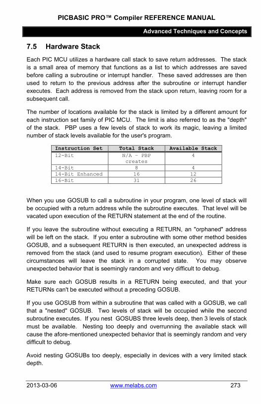
PICBASIC PRO™ Compiler REFERENCE MANUAL
Advanced Techniques and Concepts
2013-03-06 www.melabs.com 273
7.5 Hardware Stack Each PIC MCU utilizes a hardware call stack to save return addresses. The stack is a small area of memory that functions as a list to which addresses are saved before calling a subroutine or interrupt handler. These saved addresses are then used to return to the previous address after the subroutine or interrupt handler executes. Each address is removed from the stack upon return, leaving room for a subsequent call.
The number of locations available for the stack is limited by a different amount for each instruction set family of PIC MCU. The limit is also referred to as the "depth" of the stack. PBP uses a few levels of stack to work its magic, leaving a limited number of stack levels available for the user's program.
Instruction Set Total Stack Available Stack 12-Bit N/A – PBP
creates 4
14-Bit 8 4 14-Bit Enhanced 16 12 16-Bit 31 26
When you use GOSUB to call a subroutine in your program, one level of stack will be occupied with a return address while the subroutine executes. That level will be vacated upon execution of the RETURN statement at the end of the routine.
If you leave the subroutine without executing a RETURN, an "orphaned" address will be left on the stack. If you enter a subroutine with some other method besides GOSUB, and a subsequent RETURN is then executed, an unexpected address is removed from the stack (and used to resume program execution). Either of these circumstances will leave the stack in a corrupted state. You may observe unexpected behavior that is seemingly random and very difficult to debug.
Make sure each GOSUB results in a RETURN being executed, and that your RETURNs can't be executed without a preceding GOSUB.
If you use GOSUB from within a subroutine that was called with a GOSUB, we call that a "nested" GOSUB. Two levels of stack will be occupied while the second subroutine executes. If you nest GOSUBS three levels deep, then 3 levels of stack must be available. Nesting too deeply and overrunning the available stack will cause the afore-mentioned unexpected behavior that is seemingly random and very difficult to debug.
Avoid nesting GOSUBs too deeply, especially in devices with a very limited stack depth.
PICBASIC PRO™ Compiler REFERENCE MANUAL
Advanced Techniques and Concepts
274 www.melabs.com 2013-03-06
Since interrupts utilize stack memory, you should consider an extra level of stack to be unavailable when you write a program the uses interrupts.
Debugging with a Microchip tool like the ICD3 will also use up one level of stack.
The directive ON INTERRUPT will enable interrupts and one level of stack will be consumed.
The only PBP commands that are cause for concern when nesting are GOSUB and CALL. All other PBP commands may be nested with no stack concerns and no practical limit.

PICBASIC PRO™ Compiler REFERENCE MANUAL
Advanced Techniques and Concepts
2013-03-06 www.melabs.com 275
7.6 Array Handling Mechanism Array variables in PBP are written with square brackets ( [] ) to enable an index value to point to an element in an array.
my_array[15] = 0 ' Write zero to element-15 of my_array
At first glance, this seems simple and straightforward, but there is a much larger story behind the use of indexes enclosed in brackets.
Actually, a better term than index would be "offset". You can write a bracketed value next to just about any memory entity in PBP and the value will be treated as an offset to the real memory-address of the entity.
my_var VAR BYTE ' Declare a scalar byte variable my_var[15] = 0 ' Write to a RAM location that
is offset 15 locations from where my_var is allocated
7.6.1 The Danger
The techniques about to be discussed are not monitored by PBP during compilation or execution of the program. This means that you can write some crazy code that could totally wreck the RAM on the PIC MCU. PBP won't warn you or generate an error message.
The greatest opportunity for trouble lies in the fact that PBP doesn't monitor (isn't even aware) of array variable sizes. When you declare an array in PBP and specify a size, all that really happens is that PBP skips a number of RAM locations after the base variable name is allocated.
my_array VAR WORD[16] ' Allocates "my_array" as two bytes, then skips (reserves) a block of 30 bytes in RAM
Even if you blatantly write to a location that is beyond the size of an array you created, PBP won't complain.

PICBASIC PRO™ Compiler REFERENCE MANUAL
Advanced Techniques and Concepts
276 www.melabs.com 2013-03-06
my_array VAR WORD[16] my_array[87] = 0 ' Not good
This will zero a RAM location outside of your declared array. It will probably wreck another variable in your program, and PBP won't say a word about it.
When accessing arrays using variables for index values, it is always good practice to place limits on the values to inhibit them from pointing to locations that aren't within the array.
my_array VAR WORD[16] ' Declare array locations 0 through 15
IF x > 15 THEN error_1 ' Check the index variable to see if it's within the array
my_array[x] = 0 ' Only allow access if index is valid
If you're asking why PBP doesn't monitor such things, there are two good answers. The first is that it's impossible for PBP to know run-time values of index variables and the insertion of automatic validation code would consume a lot of resources. The second answer is that performing such checks would inhibit the cool stuff that follows.
7.6.2 Brackets Perform Offsets
Variable names (and alias names) in PBP represent two things to the compiler. Each name represents an address where the least-significant element is stored in RAM, and an entity-type that determines how PBP will treat the entity in subsequent encounters.
When writing any name that represents an entity in RAM (including SFRs), you can follow the name with brackets. The expression within the brackets will be treated as an offset in memory. For example, consider the following:
x = 15 FOO[x] = 0
Without knowing exactly how FOO is declared, all that we can truthfully state is that a location at address (FOO + 15) will be set to zero. The step value of the 15-address offset will be the same as the entity-type associated with the name FOO. If FOO is a BIT, a bit that is 15 bits higher in RAM will be set to zero. If FOO is a WORD, a word that is 15 words higher in RAM will be set to zero. (If the entity-type is BIT, the offset value is limited to 255.)

PICBASIC PRO™ Compiler REFERENCE MANUAL
Advanced Techniques and Concepts
2013-03-06 www.melabs.com 277
PBP doesn’t' know and doesn't care whether you've declared FOO as an array. It simply sees the bracketed offset value and the entity-type and inserts code to calculate a new address.
This is only useful if you know what lies at the offset RAM location ahead of time. The best way to know is to define something ahead of time.
7.6.3 Sub-Arrays within Arrays
Consider the following variable declarations:
all_data VAR BYTE[48] ' Array for all my data samples VAR all_data[0] ' 16 bytes for ADC samples calcs VAR all_data[16] ' 16 bytes for calculated values readings VAR all_data[32] ' 16 bytes for port readings
The intent is to create arrays for samples, calcs, and readings, but to make them subsets of the all_data array. Even though samples, calcs, and readings are only declared as aliases to single elements of all_data, they can still be accessed as arrays by slapping on a bracketed offset value:
FOR x = 0 TO 15 ADCIN 0, samples[x] ' Store ADC sample calcs[x] = samples[x]/3 ' Store calculated value readings[x] = PORTC ' Store port reading NEXT x
Now we've stored data into three arrays. Let's say that the application requires that all three arrays must be sent to a data-logging device with an HSEROUT command. Since the all_data array contains all three sub-arrays, you can write:
HSEROUT [STR all_data\48] ' Send all the data
The all_data array could be expanded to hold multiple scalar variables, also. In this example, though, all the variable types will end up as BYTEs.
7.6.4 Accessing Arrays as Multiple Variable-Types
It is possible for a single array to be declared with multiple names and for each name to be assigned a different variable type. Note that offsets for BITs are limited to a maximum value of 255.

PICBASIC PRO™ Compiler REFERENCE MANUAL
Advanced Techniques and Concepts
278 www.melabs.com 2013-03-06
In order to declare an array that can be accessed as both WORDs and BYTEs, the larger variable type must be declared first, then an alias to a modified element is declared.
my_words VAR WORD[16] my_bytes VAR my_words.BYTE0 ' Enable BYTE access to the
my_words array.
The example above creates a single array in memory that can be accessed in two different ways. With the name "my_words" the array can be accessed as 16 WORD values. With the name "my_bytes", the array can be accessed as 32 BYTE values.
One reason to do this is that PBP doesn't allow the following syntax to access a BYTE portion of a WORD array element:
my_words[x].BYTE0 = 0 'COMPILE ERROR
The long work around for this is to move the value into a temp variable, manipulate it, then restore it to the array:
temp = my_words[x] temp.BYTE0 = 0 my_words[x] = temp
If, however, the array can be accessed as both BYTEs and WORDs, you can write:
my_bytes[x*2] = 0 ' my_words[x].BYTE0 my_bytes[(x*2)+1] = 0 ' my_words[x].BYTE1
Modifiers like BYTE0 change the variable type that PBP perceives when an alias is declared. When we write "..VAR x.BYTE0", PBP will always typecast the alias as a BYTE, regardless of the variable type of "x".
The first element (element-0) of an array can be referenced without an index value. "my_words[0]" is the same as "my_words".
One last bit of information that is implied above: You can write aliases to other aliases. In the above example, you could create a name for a BYTE variable at the end of the array with:
last_byte VAR my_bytes[31]
This works even though "my_bytes" is, itself, an alias.

PICBASIC PRO™ Compiler REFERENCE MANUAL
Advanced Techniques and Concepts
2013-03-06 www.melabs.com 279
7.6.5 Applying Offsets to Bits within a Variable or Register
Another powerful result of the array-handling mechanism in PBP is that offsets may be applied to bits when accessing RAM entities. The application for this is most often associated with the need to choose a pin on a port using a variable value, but it also works for accessing bits within variables.
The individual bits within a port register are normally accessed with a period and number after the name of the register:
PORTB.0 = 1 ' Set RB0 high
But, if you need to choose the pin with a variable value, it's illegal to write:
PORTB.x = 1 ' COMPILE ERROR
The array mechanism in PBP offers a solution. An offset enclosed in brackets may be written after the bit number:
PORTB.0[x] = 1 ' Set RBx high
The actual effect of this is to add the value of x to the numeric bit number.
x = 2 PORTB.4[x] = 1 ' Set bit(4+x) high. In this
case, bit-6 is set.
NOTE THAT PBP COMMANDS WON'T ACCEPT THIS SYNTAX for command parameters. This method can only be used in expressions and with direct register access. You CANNOT write:
HIGH PORTB.0[x] ' COMPILE ERROR COUNT PORTB.0[x], 100, y ' COMPILE ERROR
When using this method, PBP will allow an offset value up to 255. As discussed before, there is no built-in protection against accessing bits that are beyond the scope of the parent entity. If you overflow the bits within the parent entity, PBP will access bits in the next higher location of memory.

PICBASIC PRO™ Compiler REFERENCE MANUAL
Appendixes
280 www.melabs.com 2013-03-06
Chapter 8: Appendixes

PICBASIC PRO™ Compiler REFERENCE MANUAL
Debugging and Troubleshooting
2013-03-06 www.melabs.com 281
8.1 Debugging and Troubleshooting There are several areas of programming for PIC MCUs that are commonly overlooked, especially by beginners. It is impossible to list all the details for all the hundreds of devices supported by PBP, but this section will try to give you some direction.
8.1.1 Configuration
See #CONFIG. Incorrect configuration of the target MCU can stop the MCU from running. It can also cause unexpected behavior.
Make sure the oscillator is configured correctly. External crystals with frequencies greater than 4MHz need a "High Speed" setting (HS). If you plan for the chip to run without an external oscillator source, make sure the oscillator configuration is set so that the internal oscillator is selected.
Low Voltage Programming should be disabled. If this is enabled and the LVP pin is left floating, the device may start and stop for no apparent reason.
Disable Extended Instruction Set. PBP doesn't use the extended instructions. Bizarre behavior has been observed when enabled.
Other configuration settings may need to be changed to match your intent and your hardware design.
8.1.2 Initializing values
Upon program startup, you should expect values in variables to be random. They will not be zeros or any other predictable value. If your program depends on a starting value for any variable, you must set that value at the beginning of your program.
The same is true for port output values. Don't assume that outputs will be in a low state upon startup. Initialize all PORT and GPIO values explicitly.
8.1.3 DEFINE OSC
DEFINE OSC tells PBP what system clock frequency to expect. Without it, PBP assumes that a 4MHz clock is in use. If the actual frequency is different than the frequency PBP expects, all timed commands in PBP will give incorrect results.

PICBASIC PRO™ Compiler REFERENCE MANUAL
Debugging and Troubleshooting
282 www.melabs.com 2013-03-06
Play it safe and always use DEFINE OSC.
DEFINE OSC 4 ' Compile for 4MHz clock
8.1.4 Analog Inputs
If there are analog inputs for converters and/or comparators on the target MCU, they will usually default to analog mode on the pins. This will interfere with digital operations performed on pins that also function as analog inputs. For digital use of pins with analog options, you must find and set a register to select digital mode for the pins.
Here are a few examples for a handful of MCUs, but remember that PBP supports more than 400 different devices. Don't assume that the settings are consistent from one device to the next.
ANSEL = %00000000 ' 16F88, 16F688, 16F690, 16F88x ANSELH = %00000000 ' 16F690, 16F88x ADCON1 = %00000111 ' 16F87x, 16F87xA, 18F452 ADCON1 = %00001111 ' 18F4620
In the Microchip datasheet for the specific device you are using, the analog/digital selection will be located either in the I/O Ports section or the Analog/Digital Converter section. Common register names are ANSEL, ANSELH, ANSELA-ANSELG, ANCONx, ADCONx.
These settings are important. Save yourself some time and search the datasheet.
8.1.5 Internal Oscillator
A lot of devices are equipped with an internal oscillator, and these are widely used for convenience and to save component cost. In many cases, though, there are register settings that are needed to get the expected behavior from the internal osc.
Many parts have a register which selects the frequency of the internal osc. This is usually covered in the datasheet under Oscillator Configuration.
OSCCON = $70 ' Set internal to 8MHz for PIC16F88
Older devices may need a calibration process in order for the internal oscillator to be accurate.
PICBASIC PRO™ Compiler REFERENCE MANUAL
Debugging and Troubleshooting
2013-03-06 www.melabs.com 283
DEFINE OSCCAL_1K 1 ' Calibrate internal osc for PIC12F675
8.1.6 Read-Modify-Write
Changing the state of an output pin on a PIC MCU is not a simple one-way operation. Even though you're writing to a single bit on a port, the operation starts with a read of the entire port. Consider the simple example:
PORTB.0 = 1
The MCU makes this happen by reading all pins in PORTB, changing the Bit-0 value per your command, then writing all the bits back to the port. This is transparent as long as all of the pins on PORTB can be read correctly, but sometimes they can't.
Keep in mind that when the state of the pin is changed, the actual voltage will not change instantaneously. In a good situation, the voltage will change within one instruction cycle after commanded… perhaps with a 50nS delay. But, if the pin is affected somehow by its external connection, the voltage could be delayed much longer.
Problems can arise when the individual pins on a single port are changed in rapid succession:
PORTB.0 = 1 PORTB.1 = 0 PORTB.7 = 1
The microcontroller executes these commands VERY quickly. When the last line is executed to set the PORTB.7 pin, all the pins on PORTB are read and rewritten. If pins 0 and 1 haven't had time for the actual voltage to change, the states of these pins will be incorrectly read and then rewritten with the incorrect value.
The PIC18 family devices offer an alternative register that is immune to this phenomenon. In these parts you can write:

PICBASIC PRO™ Compiler REFERENCE MANUAL
Debugging and Troubleshooting
284 www.melabs.com 2013-03-06
LATB.0 = 1 LATB.1 = 0 LATB.7 = 1
Another approach would be to write the register as a single value. The concern here is the PORTB pins we haven't mentioned (2 through 6). If these pins are inputs or if you don't care about their output states, simply set them to zeros when writing the port:
PORTB = %10000001 ' pin0=1, pin1=0, pin7=1
You may also be able to change the order of the settings so that slow-reacting pins are set last. Delays could be placed after settings to slow-reacting pins. You could also address this in the design stage, by placing pin connections on different ports.
8.1.7 Data Direction
All I/O pins on all PIC MCUs are configured as inputs by default. In order for a pin to be used as an output, a data-direction register must be changed.
PBP's HIGH, LOW, and TOGGLE commands change the data-direction to output automatically, but they do it every time they are executed. This can needlessly use instruction cycles.
It is a simple matter to change data-direction. This is usually done in an initialization section that is written near the top of the program. After the data-direction is set once, it won't change unless something in your program affects it.
init: TRISB = %11111011 ' All PORTB pins inputs except
PORTB.2 main: PORTB.2 = 1 ' Set PORTB.2 high PAUSE 500 ' Pause half second PORTB.2 = 0 ' Set PORTB.2 low PAUSE 500 ' Pause half second GOTO main
If using aliases to name pins and you don't want to set the data-direction register by name, you can use PBP's INPUT and OUTPUT commands to automatically determine the data-direction register and set it.

PICBASIC PRO™ Compiler REFERENCE MANUAL
Debugging and Troubleshooting
2013-03-06 www.melabs.com 285
led VAR PORTB.2 ' Alias name for pin init: OUTPUT led ' Make led an output pin main: PORTB.2 = 1 ' Set PORTB.2 high ..
8.1.8 Analog Conversion
If your ADCIN command is misbehaving, there are probably some register settings that will help. All of the following can be found in the Analog/Digital Converter section of the datasheet for your specific part. Don't assume that one part works exactly like another.
The MCU always stores the result of an analog conversion in a 16-bit register pair. If "DEFINE ADC_BITS 8" is used, PBP takes a shortcut and only reads the most significant byte of the result. Microchip has accommodated this by LEFT-JUSTIFYING the result in the register pair by default.
However, when ADC_BITS is defined as greater than 8, PBP will read all 16-bits of the register pair. For the result to be correct without a subsequent shift operation, you can tell the chip to RIGHT-JUSTIFY the result. Here are a couple of examples that come with our standard warning… Don't assume that one part works exactly like another! Check the datasheet.
ADCON1.7 = 1 ' Right-justify ADC result for PIC16F877
ADCON0.7 = 1 ' Right-justify ADC result for PIC12F683
Another common issue that affects ADCIN is the ADC clock setting. You should use "DEFINE ADC_CLOCK" to set a number that corresponds to the desired setting from the datasheet, but some devices defy PBP's attempts to translate the define. It's always safe to use a register setting in addition to the define:
DEFINE ADC_CLOCK 3 ' Inoperative on PIC16F887 ADCON0 = %11000000 ' Set ADC_CLOCK for PIC16F887

PICBASIC PRO™ Compiler REFERENCE MANUAL
Debugging and Troubleshooting
286 www.melabs.com 2013-03-06
8.1.9 I/O pin parameters and limitations
On a PIC microcontroller, not all pins are created equal. Some pins have more current-capability than others. Some are built as open-drain drivers. Some can only be used as input.
The datasheet for the specific device you are using will have the details.
8.1.10 Piggybacked pin functions
Most pins on most PIC MCUs will have multiple functions available. In some cases, a "piggybacked" function of a pin will interfere with the pin's function as a normal, digital I/O (as in the previously discussed case of analog inputs).
If a pin is behaving unexpectedly, check the pin's description in the datasheet for the specific device that you are using. You may need to do some digging in the datasheet to find descriptions of each function assigned to the pin. Look to the default register settings (reset states) to determine how the pin is configured.
An example of this is encountered on some small MCUs of the 12-bit instruction set variety (PIC10 and some PIC12). On these devices, the pin GPIO.2 is forced to an input due to its function as a timer/counter clock input. To disable this function and allow the pin to work as a normal, digital I/O, you would set bit-5 in OPTION_REG to zero:
OPTION_REG.5 = 0
8.1.11 Pin Relocation and Defines
Some PIC MCUs offer options to move hardware peripheral I/O from one pin to another. For the PBP commands that depend on these hardware peripherals, PBP needs to be told where you've assigned the pin. If the hardware peripheral I/O on the MCU you've chosen cannot be relocated, PBP will automatically use the pin location that is available and no additional defines are required.
The most common example is related to PBP's HPWM command. On most PIC MCUs, the output for this command is limited to a few channels on dedicated pins that can't be relocated (CCP channels). On some devices, however, a single CCP channel can be relocated. This occurs on the PIC16F88, where CCP1 can be configured to output on PORTB.0 or PORTB.3. For this situation, PBP needs a DEFINE in order to know where the HPWM will be output. This DEFINE doesn't affect the actual configuration, it only tells PBP which configuration to expect.
PICBASIC PRO™ Compiler REFERENCE MANUAL
Debugging and Troubleshooting
2013-03-06 www.melabs.com 287
DEFINE CCP1_REG PORTB ' Locate CCP1 port and bit DEFINE CCP1_BIT 3
These defines will be listed in the associated command pages. More information for the example above can be found in the HPWM section.
8.1.12 Omitting parentheses
While most users realize the importance of parentheses in mathematical expressions, a common mistake is to omit parentheses in logical expressions. It's important to realize that, without parentheses, the logic can be interpreted differently: Consider this example:
IF x = 0 AND y = 0 OR z = 0 THEN label
The conditional here is ambiguous, at best. It should be written with parentheses to make clear the intent. Here are two ways to write it that give entirely different results. To illustrate the point, try to decide which one will give the same result as the above example:
IF ((x = 0) AND (y = 0)) OR (z = 0) THEN label IF (x = 0) AND ((y = 0) OR (z = 0)) THEN label
Parentheses are strongly encouraged in all expressions, be they mathematical, comparison, bitwise, logical, or any combination.
8.1.13 Channel numbers vs. pins
Some commands, like ADCIN and HPWM, use channel numbers instead of port.pin descriptions. A common mistake is to write the port.pin instead of the channel. .
ADCIN PORTA.0, adc_result ' DON'T DO THIS
The above example will read the digital state of PORTA.0, then perform an analog conversion on either channel-0 or channel-1, depending on what it received for state data. If the intent is to perform ADCIN on channel-0, the correct syntax is:
ADCIN 0, adc_result

PICBASIC PRO™ Compiler REFERENCE MANUAL
Debugging and Troubleshooting
288 www.melabs.com 2013-03-06
8.1.14 Hardware Stack
Too many nested GOSUBs, or entering and exiting subroutines incorrectly may corrupt the hardware call stack on the PIC MCU. This can cause unexpected resets and some intermittent bizarre behavior.
See section 7.5 Hardware Stack for more information.
8.1.15 Overrunning Array Variables
When you declare an array variable with 16 elements, those elements are numbered 0-15. Writing to element-16 will write to a memory location beyond the end of the memory reserved for the array.
Because of the open-ended nature of the array variable handling in PBP, an error will not be reported if you write data past the end location of an array variable that you have declared.
my_array VAR BYTE[16] my_array[24] = 0 'No error, but results in
corrupted memory
It is good practice to write in limits when accessing arrays with variable indexes.
my_array VAR BYTE[16] my_array[x MIN 15] ' Limit index expression to
maximum value of 15 my_array[x & $0F] ' Use a bitwise mask to limit
See section 7.6 Array Handling Mechanism for more information.

PICBASIC PRO™ Compiler REFERENCE MANUAL
12-Bit Instruction Set Considerations
2013-03-06 www.melabs.com 289
8.2 12-Bit Instruction Set Considerations Because of the architecture of the 12-bit instruction-set PIC MCUs, programs compiled for them by PBP will, in general, be larger and slower than programs compiled for the other PIC MCU families. In many cases, choosing a device from one of these other families will be more appropriate. However, many useful programs can be written and compiled for the 12-bit instruction set.
The two main programming limitations that will most likely occur are running out of RAM memory for variables and running past the first 256 word limit for the library routines. These limitations have made it necessary to eliminate some compiler commands and modify the operation of some others.
The compiler for 12-bit instruction set uses between 20 and 22 bytes of RAM for its internal variables, with additional RAM used for any necessary temporary variables. This RAM allocation includes a 4 level software stack so that the BASIC program can still nest GOSUBs up to 4 levels deep. Some PIC MCU devices only have 24 or 25 bytes of RAM so there is very little space for user variables on those devices. If the Unable to Fit Variable error message occurs during compilation, choose another PIC MCU with more general purpose RAM.
PIC MCUs with the 12-bit instruction set can call only into the first half (256 words) of a code page. Since the compiler's library routines are all accessed by calls, they must reside entirely in the first 256 words of the PIC MCU code space. Many library routines, such as I2CREAD, are fairly large. It may only take a few routines to overrun the first 256 words of code space. If it is necessary to use more library routines than will fit into the first half of the first code page, it will be necessary to move to a 14- or 16-bit instruction set instead of the 12-bit.

PICBASIC PRO™ Compiler REFERENCE MANUAL
PBPX Command Line Operation
290 www.melabs.com 2013-03-06
8.3 PBPX Command Line Operation PBPX <Options> <Filename>
Options: -h or -? Display command line help on the screen. -n Enable LONG variables for PIC18. (PBPL) -p<pic> Specify target MCU. [-p18F4620] -a<assembler> Specify assembler executable. [-aMPASMWIN] -o<asm param> Pass command line parameter to assembler. [-os] -k+ or -k# Add source-level debugging information (COFF). -k- Add assembler-level debugging information (COFF). -c Insert source comments into compiled output. -s Suppress assembler (compile only). -v Verbose mode. -i Set include paths. -l<library> Use alternate library. [-lPBPPIC18.LIB] -d<user #DEFINE> User-created #DEFINE [-dFOO]
Although most users will depend upon an integrated development environment (IDE) to control PBP, under the hood it remains an application that is operated by the use of command-line parameters (aka switches).
This section is intended to guide those who need to operate PBP from the command line and those who wish to install PBP as a language tool within their favorite, generic IDE or program editor.
This information is only applicable to PBP3 and later versions. Older versions of PBP use different executable filenames and may use different parameters.
The name of the PBP executable is PBPX.EXE.
Before launching PBPX, the location of the assembler executable should be placed in an environment variable named PBP_MPASM.
Before launching PBPX, the working directory should be set to the location of the source program files.
The slash (/) character may be used instead of the dash. Multiple command-line options may be separated by a space. However, no space should intervene between an option and its argument. Multiple options of the same type may be used.

PICBASIC PRO™ Compiler REFERENCE MANUAL
PBPX Command Line Operation
2013-03-06 www.melabs.com 291
With the working directory set to the source folder location, PBPX must be invoked with the full path to its install location. For other install locations, substitute the real path in the examples that follow.
Usage: <path>\PBPX <Options> <Filename> Options:
-h or -? -h
When used, will override all other parameters and will cause PBPX to return a brief description of command-line options
-n -n
Causes "PBP In LONG Mode" (PBPL) to be invoked. This should only be used for PIC18 target devices.
-p<pic> -p18F4620 -p18F46K22
Used to specify the target PIC MCU for the compile. The device number should be given without the "PIC" prefix.
-a<assembler> -aMPASMWIN -aMPASMX
Used to specify the filename of the assembler executable. Should not be used with full path information (e.g. c:\program files\microchip\mpasm suite\mpasmwin). Instead, prepend the location of the assembler executable to the system's PATH environment variable.
-o<asm param> -0q- -os
May be used multiple times on the command-line. The parameter that follows –o is ignored by PBPX, except that it is passed to the assembler command line preceded by a slash character. If you write:
-aMPASMWIN –oq –os
The resulting command line that invokes the assembler will include:
MPASMWIN /q /s
-k+ or -k# -k+ -k#
Causes PBPX to rewrite the assembler-created .COF file with source-level debugging data. The switch is required for source-level debugging in MPLAB.
PICBASIC PRO™ Compiler REFERENCE MANUAL
PBPX Command Line Operation
292 www.melabs.com 2013-03-06
-k- -k-
Instructs PBPX to rewrite the assembler-created .COF file with assembly-level debugging data. Source-level debugging will be disabled in MPLAB, allowing debugging in Assembly Language.
-c -s
Instructs PBPX to insert BASIC program lines as comments in the generated .ASM file.
-s -s
Causes PBPX to create the .ASM file, but the assembler will not be invoked. Cannot be used with –k options.
-v -v
Cause PBPX to return a more detailed report of its actions during compilation.
-i<path> -iC:\PBP\MY_INCLUDES
Instructs PBPX to search the specified path for include files during compilation. Since spaces are not allowed in the path, this option is of limited use on modern Windows systems.
-l<library> PBPPIC18.LIB
Instructs PBPX to override the LIBRARY directive found in the .PBPINC file and, instead, use the library file specified here.
-d<user_#DEFINE> -dFOO
May be used multiple times on the command line. This parameter allows the user to create the equivalent of a #DEFINE directive from the command line instead of from the source program. This option may be used multiple times on a single command line. Spaces are not allowed in the –d text.
Here are some examples of –d usage and their equivalent program code:
-dFOO #DEFINE FOO -dFOO=1 #DEFINE FOO 1
String constants may not be defined with –d.
Examples of command lines:

PICBASIC PRO™ Compiler REFERENCE MANUAL
PBPX Command Line Operation
2013-03-06 www.melabs.com 293
C:\PBP\PBPX -n -p18F4620 -aMPASMWIN -os -k# blink.pbp
Compiles blink.pbp for the PIC18F4620 using PBPL. The MPASMWIN assembler is invoked with its /s parameter, causing its progress dialog to close automatically. The COFF file is rewritten after assembly to accommodate source-level debugging.
C:\PBP\PBPX -p16F88 -aMPASMWIN -k# blink.pbp -dver2
Compiles blink.pbp for the PIC16F88 using the MPASMWIN assembler.

PICBASIC PRO™ Compiler REFERENCE MANUAL
Specifying Assembler Location with PBP_MPASM
294 www.melabs.com 2013-03-06
8.4 Specifying Assembler Location with PBP_MPASM As discussed earlier in this manual, PBP must invoke an assembler application to finish the compile/assembly process. The assembler executable name is set with the –a command line option. This is usually handled by the IDE in the form of a compiler option setting.
The location of the assembler folder on the system is held in an environment variable named PBP_MPASM. This variable holds path location in the form of a string value. An example is: "C:\Program Files\Microchip\MPASM Suite\"
When launching the assembler, PBP will look first in the location that it finds in the PBP_MPASM variable. If the assembler executable is not found there, PBP will continue its search using all locations available in the system's PATH environment variable.
The PBP_MPASM variable is set automatically after installation of PBP, when the system is next restarted. The installer will search for the most recent installation of MPLAB and set the value to the assembler folder within that installation.
If you install a new version of MPLAB in a different path, the PBP_MPASM variable will need to be updated with the new assembler location. A utility for this may be found in the Start Menu Program Group for PBP.

PICBASIC PRO™ Compiler REFERENCE MANUAL
defs Include Files
2013-03-06 www.melabs.com 295
8.5 defs Include Files Your PBP installation includes some special-purpose files that may be included in your program code. These files are mostly made up of constant and variable declaration statements that make PBP more compatible with other (simplified and limited) languages. Details are most easily found by reading the contents of the files.
8.5.1 modedefs.bas
INCLUDE "modedefs.bas"
The file modedefs.bas gives names to modes used in commands like SERIN/SEROUT and SHIFTIN/SHIFTOUT. An example would be the name "T9600" in the SERIN command. "T9600" is a constant which is defined in modedefs.bas.
modedefs.bas is not needed for every PBP program. It is only needed for programs where mode names are used instead of the actual mode numbers. Even when mode names are used, you have the option of creating the names in your program instead of including modedefes.bas, which will create many names that you may not use.
8.5.2 bs1defs.bas
INCLUDE "bs1defs.bas"
The file bs1defs.bas creates a set of variables and aliases with names that are identical to those pre-defined by the BASIC Stamp (first version, BS1) by Parallax. These names are also identical to those pre-defined by PICBASIC Compiler (aka PBC) by melabs.
8.5.3 bs2defs.bas
INCLUDE "bs2defs.bas"
The file bs2defs.bas creates a set of variables and aliases with names that are identical to those pre-defined by the BASIC Stamp (second version, BS2) by Parallax.

PICBASIC PRO™ Compiler REFERENCE MANUAL
SERIN2/SEROUT2 Mode List
296 www.melabs.com 2013-03-06
8.6 SERIN2/SEROUT2 Mode List Common modes for commands SERIN2 and SEROUT2:
Baud Rate Bit 15 (Output)
Bit 14 (Conversion)
Bit 13 (Parity)
Mode Number
300 Driven True None 3313 300 Driven True Even* 11505 300 Driven Inverted None 19697 300 Driven Inverted Even* 27889 300 Open True None 36081 300 Open True Even* 44273 300 Open Inverted None 52465 300 Open Inverted Even* 60657 600 Driven True None 1646 600 Driven True Even* 9838 600 Driven Inverted None 18030 600 Driven Inverted Even* 26222 600 Open True None 34414 600 Open True Even* 42606 600 Open Inverted None 50798 600 Open Inverted Even* 58990 1200 Driven True None 813 1200 Driven True Even* 9005 1200 Driven Inverted None 17197 1200 Driven Inverted Even* 25389 1200 Open True None 33581 1200 Open True Even* 41773 1200 Open Inverted None 49965 1200 Open Inverted Even* 58157 2400 Driven True None 396 2400 Driven True Even* 8588 2400 Driven Inverted None 16780 2400 Driven Inverted Even* 24972 2400 Open True None 33164 2400 Open True Even* 41356 2400 Open Inverted None 49548 2400 Open Inverted Even* 57740 4800 Driven True None 188 4800 Driven True Even* 8380 4800 Driven Inverted None 16572 4800 Driven Inverted Even* 24764 4800 Open True None 32956 4800 Open True Even* 41148 4800 Open Inverted None 49340 4800 Open Inverted Even* 57532
*Parity is odd when DEFINE SER2_ODD 1 is used. Continued…

PICBASIC PRO™ Compiler REFERENCE MANUAL
SERIN2/SEROUT2 Mode List
2013-03-06 www.melabs.com 297
Baud Rate Bit 15 (Output)
Bit 14 (Conversion)
Bit 13 (Parity)
Mode Number
9600 baud may be unreliable with 4MHz clock 9600 Driven True None 84 9600 Driven True Even* 8276 9600 Driven Inverted None 16468 9600 Driven Inverted Even* 24660 9600 Open True None 32852 9600 Open True Even* 41044 9600 Open Inverted None 49236 9600 Open Inverted Even* 57428
baud rates below require 8MHz clock or faster 14400 Driven True None 49 14400 Driven True Even* 8241 14400 Driven Inverted None 16433 14400 Driven Inverted Even* 24625 14400 Open True None 32817 14400 Open True Even* 41009 14400 Open Inverted None 49201 14400 Open Inverted Even* 57393
baud rates below require 10MHz clock or faster 19200 Driven True None 32 19200 Driven True Even* 8224 19200 Driven Inverted None 16416 19200 Driven Inverted Even* 24608 19200 Open True None 32800 19200 Open True Even* 40992 19200 Open Inverted None 49184 19200 Open Inverted Even* 57376
baud rates below require 16MHz clock or faster 28800 Driven True None 15 28800 Driven True Even* 8207 28800 Driven Inverted None 16399 28800 Driven Inverted Even* 24591 28800 Open True None 32783 28800 Open True Even* 40975 28800 Open Inverted None 49167 28800 Open Inverted Even 57359
baud rates below require 20MHz clock or faster 38400 Driven True None 6 38400 Driven True Even* 8198 38400 Driven Inverted None 16390 38400 Driven Inverted Even* 24582 38400 Open True None 32774 38400 Open True Even* 40966 38400 Open Inverted None 49158 38400 Open Inverted Even 57350
*Parity is odd when DEFINE SER2_ODD 1 is used.

PICBASIC PRO™ Compiler REFERENCE MANUAL
DEFINEs
298 www.melabs.com 2013-03-06
8.7 Defines DEFINE ADC_BITS 8 'Number of bits in ADCIN result DEFINE ADC_CLOCK 3 'ADCIN clock source (rc = 3) DEFINE ADC_SAMPLEUS 50 'ADCIN sampling time in
microseconds (pause after channel is selected)
DEFINE BUTTON_PAUSE 10 'BUTTON debounce delay in ms DEFINE CCP1_REG PORTC 'HPWM channel 1 pin port DEFINE CCP1_BIT 2 'HPWM channel 1 pin bit DEFINE CCP2_REG PORTC 'HPWM channel 2 pin port DEFINE CCP2_BIT 1 'HPWM channel 2 pin bit DEFINE CCP3_REG PORTG 'HPWM channel 3 pin port DEFINE CCP3_BIT 0 'HPWM channel 3 pin bit DEFINE CCP4_REG PORTG 'HPWM channel 4 pin port DEFINE CCP4_BIT 3 'HPWM channel 4 pin bit DEFINE CCP5_REG PORTG 'HPWM channel 5 pin port DEFINE CCP5_BIT 4 'HPWM channel 5 pin bit DEFINE CHAR_PACING 1000 'SEROUT character pacing in us DEFINE DEBUG_REG PORTB 'DEBUG pin port DEFINE DEBUG_BIT 0 'DEBUG pin bit DEFINE DEBUG_BAUD 2400 'DEBUG baud rate DEFINE DEBUG_MODE 1 'DEBUG mode: 0 = True, 1 =
Inverted DEFINE DEBUG_PACING 1000 'DEBUG character pacing in us DEFINE DEBUGIN_REG PORTB 'DEBUGIN pin port DEFINE DEBUGIN_BIT 0 'DEBUGIN pin bit DEFINE DEBUGIN_MODE 1 'DEBUGIN mode: 0 = True, 1 =
Inverted DEFINE HPWM2_TIMER 1 'HPWM channel 2 timer select DEFINE HPWM3_TIMER 1 'HPWM channel 3 timer select DEFINE HSER_BAUD 2400 'HSER baud rate DEFINE HSER_SPBRG 25 'HSER SPBRG init DEFINE HSER_SPBRGH 0 'HSER SPBRGH init DEFINE HSER_RCSTA 90h 'HSER receive status init DEFINE HSER_TXSTA 20h 'HSER transmit status init DEFINE HSER_EVEN 1 'HSER If even parity desired DEFINE HSER_ODD 1 'HSER If odd parity desired DEFINE HSER_BITS 9 'HSER Use for 8 bits + parity DEFINE HSER_CLROERR 1 'Automatically clear HSERIN
overflow errors DEFINE HSER_PORT 1 'HSER port to use on devices
with more than one DEFINE HSER2_BAUD 2400 'HSER2 baud rate DEFINE HSER2_SPBRG 25 'HSER2 SPBRG2 init DEFINE HSER2_SPBRGH 0 'HSER2 SPBRGH2 init DEFINE HSER2_RCSTA 90h 'HSER2 receive status init DEFINE HSER2_TXSTA 20h 'HSER2 transmit status init DEFINE HSER2_EVEN 1 'HSER2 If even parity desired
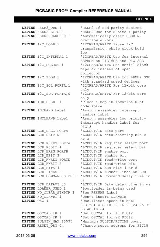
PICBASIC PRO™ Compiler REFERENCE MANUAL
DEFINEs
2013-03-06 www.melabs.com 299
DEFINE HSER2_ODD 1 'HSER2 If odd parity desired DEFINE HSER2_BITS 9 'HSER2 Use for 8 bits + parity DEFINE HSER2_CLROERR 1 'Automatically clear HSERIN2
overflow errors DEFINE I2C_HOLD 1 'I2CREAD/WRITE Pause I2C
transmission while clock held low
DEFINE I2C_INTERNAL 1 'I2CREAD/WRITE Use for internal EEPROM on PIC16CE and PIC12CE
DEFINE I2C_SCLOUT 1 'I2CREAD/WRITE Set serial clock bipolar instead of open-collector
DEFINE I2C_SLOW 1 'I2CREAD/WRITE Use for >8MHz OSC with standard speed devices
DEFINE I2C_SCL PORTA,1 'I2CREAD/WRITE For 12-bit core only
DEFINE I2C_SDA PORTA,0 'I2CREAD/WRITE For 12-bit core only
DEFINE ICD_USED 1 'Place a nop in location-0 of code space
DEFINE INTHAND Label 'Assign assembler interrupt handler label
DEFINE INTLHAND Label 'Assign assembler low priority interrupt handler label for PIC18
DEFINE LCD_DREG PORTA 'LCDOUT/IN data port DEFINE LCD_DBIT 0 'LCDOUT/IN data starting bit 0
or 4 DEFINE LCD_RSREG PORTA 'LCDOUT/IN register select port DEFINE LCD_RSBIT 4 'LCDOUT/IN register select bit DEFINE LCD_EREG PORTB 'LCDOUT/IN enable port DEFINE LCD_EBIT 3 'LCDOUT/IN enable bit DEFINE LCD_RWREG PORTE 'LCDOUT/IN read/write port DEFINE LCD_RWBIT 2 'LCDOUT/IN read/write bit DEFINE LCD_BITS 4 'LCDOUT/IN bus size 4 or 8 DEFINE LCD_LINES 2 'LCDOUT/IN Number lines on LCD DEFINE LCD_COMMANDUS 2000 'LCDOUT/IN Command delay time in
us DEFINE LCD_DATAUS 50 'LCDOUT/IN Data delay time in us DEFINE LOADER_USED 1 'Bootloader is being used DEFINE NO_CLEAR_STKPTR 1 'See RESUME Label DEFINE NO_CLRWDT 1 'Don’t insert CLRWDTs DEFINE OSC 4 'Oscillator speed in MHz:
3(3.58) 4 8 10 12 16 20 24 25 32 33 40 48 64
DEFINE OSCCAL_1K 1 'Set OSCCAL for 1K PIC12 DEFINE OSCCAL_2K 1 'Set OSCCAL for 2K PIC12 DEFINE PULSIN_MAX 65535 'Maximum PULSIN/RCTIME count DEFINE RESET_ORG 0h 'Change reset address for PIC18

PICBASIC PRO™ Compiler REFERENCE MANUAL
DEFINEs
300 www.melabs.com 2013-03-06
DEFINE SER2_BITS 8 'Set number of data bits for SERIN2 and SEROUT2
DEFINE SER2_ODD 1 'Set odd parity for SERIN2 and SEROUT2
DEFINE SHIFT_PAUSEUS 50 'Slow down the SHIFTIN and SHIFTOUT clock
DEFINE USE_LFSR 1 'Use PIC18 LFSR instruction DEFINE WRITE_INT 1 'Disable/enable global
interrupts during WRITE DEFINE XINXLAT_OFF 1 'Don’t translate XIN commands to
BS2 format DEFINE XOUTXLAT_OFF 1 'Don’t translate XOUT commands
to BS2 format

PICBASIC PRO™ Compiler REFERENCE MANUAL
Reserved Words
2013-03-06 www.melabs.com 301
8.8 Reserved Words #DEFINE #ELSE #ENDIF #ERROR #IF #IFDEF #IFNDEF #MSG #WARNING ABS ADCIN AND ANDNOT ARRAYREAD ARRAYWRITE ASM ATN BANK0 BANK1 BANK2 BANK3 BANK4 BANK5 BANK6 BANK7 BANK8 BANK9 BANK10 BANK11 BANK12 BANK13 BANK14 BANK15 BANKA BIN BIN1 BIN2 BIN3 BIN4 BIN5 BIN6 BIN7 BIN8 BIN9 BIN10 BIN11 BIN12 BIN13
BIN14 BIN15 BIN16 BIN17 BIN18 BIN19 BIN20 BIN21 BIN22 BIN23 BIN24 BIN25 BIN26 BIN27 BIN28 BIN29 BIN30 BIN31 BIN32 BIT BIT0 BIT1 BIT2 BIT3 BIT4 BIT5 BIT6 BIT7 BIT8 BIT9 BIT10 BIT11 BIT12 BIT13 BIT14 BIT15 BIT16 BIT17 BIT18 BIT19 BIT20 BIT21 BIT22 BIT23 BIT24 BIT25
BIT26 BIT27 BIT28 BIT29 BIT30 BIT31 BRANCH BRANCHL BUTTON BYTE BYTE0 BYTE1 BYTE2 BYTE3 CALL CASE CLEAR CLEARWDT CON COS COUNT DATA DCD DEBUG DEBUGIN DEC DEC1 DEC2 DEC3 DEC4 DEC5 DEC6 DEC7 DEC8 DEC9 DEC10 DEFINE DIG DISABLE DIV32 DO DTMFOUT EEPROM ELSE ELSEIF ENABLE

PICBASIC PRO™ Compiler REFERENCE MANUAL
Reserved Words
302 www.melabs.com 2013-03-06
END ENDASM ENDIF ERASECODE EXIT EXT FLAGS FOR FREQOUT GOP GOSUB GOTO HEX HEX1 HEX2 HEX3 HEX4 HEX5 HEX6 HEX7 HEX8 HIGH HIGHBYTE HIGHWORD HPWM HSERIN HSERIN2 HSEROUT HSEROUT2 HYP I2CREAD I2CWRITE IBIN IBIN1 IBIN2 IBIN3 IBIN4 IBIN5 IBIN6 IBIN7 IBIN8 IBIN9 IBIN10 IBIN11 IBIN12 IBIN13 IBIN14 IBIN15
IBIN16 IBIN17 IBIN18 IBIN19 IBIN20 IBIN21 IBIN22 IBIN23 IBIN24 IBIN25 IBIN26 IBIN27 IBIN28 IBIN29 IBIN30 IBIN31 IBIN32 IDEC IDEC1 IDEC2 IDEC3 IDEC4 IDEC5 IDEC6 IDEC7 IDEC8 IDEC9 IDEC10 IF IHEX IHEX1 IHEX2 IHEX3 IHEX4 IHEX5 IHEX6 IHEX7 IHEX8 INCLUDE INPUT INTERRUPT IS ISBIN ISBIN1 ISBIN2 ISBIN3 ISBIN4 ISBIN5
ISBIN6 ISBIN7 ISBIN8 ISBIN9 ISBIN10 ISBIN11 ISBIN12 ISBIN13 ISBIN14 ISBIN15 ISBIN16 ISBIN17 ISBIN18 ISBIN19 ISBIN20 ISBIN21 ISBIN22 ISBIN23 ISBIN24 ISBIN25 ISBIN26 ISBIN27 ISBIN28 ISBIN29 ISBIN30 ISBIN31 ISBIN32 ISDEC ISDEC1 ISDEC2 ISDEC3 ISDEC4 ISDEC5 ISDEC6 ISDEC7 ISDEC8 ISDEC9 ISDEC10 ISHEX ISHEX1 ISHEX2 ISHEX3 ISHEX4 ISHEX5 ISHEX6 ISHEX7 ISHEX8

PICBASIC PRO™ Compiler REFERENCE MANUAL
Reserved Words
2013-03-06 www.melabs.com 303
LCDIN LCDOUT LET LIBRARY LONG LOOKDOWN LOOKDOWN2 LOOKUP LOOKUP2 LOOP LOW LOWBYTE LOWWORD MAX MIN NAP NCD NEXT NOT OR ORNOT OUTPUT OWIN OWOUT PAUSE PAUSEUS PEEK PEEKCODE PIN POKE POKECODE POT PULSIN PULSOUT PWM R0 R1 R2 R3 R4 R5 R6 R7 R8 RANDOM RB1** RB2**
RCTIME READ READCODE REM REP REPEAT RESUME RETURN REV REVERSE RM1 RM2 RR1 RR2 RS1*** RS2*** SBIN SBIN1 SBIN2 SBIN3 SBIN4 SBIN5 SBIN6 SBIN7 SBIN8 SBIN9 SBIN10 SBIN11 SBIN12 SBIN13 SBIN14 SBIN15 SBIN16 SBIN17 SBIN18 SBIN19 SBIN20 SBIN21 SBIN22 SBIN23 SBIN24 SBIN25 SBIN26 SBIN27 SBIN28 SBIN29 SBIN30 SBIN31
SBIN32 SDEC SDEC1 SDEC2 SDEC3 SDEC4 SDEC5 SDEC6 SDEC7 SDEC8 SDEC9 SDEC10 SELECT SERIN SERIN2 SEROUT SEROUT2 SHEX SHEX1 SHEX2 SHEX3 SHEX4 SHEX5 SHEX6 SHEX7 SHEX8 SHIFTIN SHIFTOUT SIN SKIP SLEEP SOFT_STACK* SOFT_STACK _PTR* SOUND SQR STEP STOP STR SWAP SYMBOL SYSTEM THEN TO TOGGLE UNTIL USBIN

PICBASIC PRO™ Compiler REFERENCE MANUAL
Reserved Words
304 www.melabs.com 2013-03-06
USBINIT USBOUT USBSERVICE USER VAR WAIT WAITSTR WEND WHILE WORD WORD0 WORD1 WRITE WRITECODE XIN XOR XORNOT
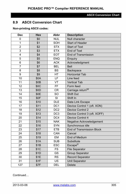
PICBASIC PRO™ Compiler REFERENCE MANUAL
ASCII Conversion Chart
2013-03-06 www.melabs.com 305
8.9 ASCII Conversion Chart Non-printing ASCII codes:
Dec Hex Abbr Description 0 $0 NUL Null character 1 $1 SOH Start of Header 2 $2 STX Start of Text 3 $3 ETX End of Text 4 $4 EOT End of Transmission 5 $5 ENQ Enquiry 6 $6 ACK Acknowledgment 7 $7 BEL Bell 8 $8 BS Backspace 9 $9 HT Horizontal Tab 10 $0A LF Line feed 11 $0B VT Vertical Tab 12 $0C FF Form feed 13 $0D CR Carriage return[g] 14 $0E SO Shift Out 15 $0F SI Shift In 16 $10 DLE Data Link Escape 17 $11 DC1 Device Control 1 (oft. XON) 18 $12 DC2 Device Control 2 19 $13 DC3 Device Control 3 (oft. XOFF) 20 $14 DC4 Device Control 4 21 $15 NAK Negative Acknowledgement 22 $16 SYN Synchronous idle 23 $17 ETB End of Transmission Block 24 $18 CAN Cancel 25 $19 EM End of Medium 26 $1A SUB Substitute 27 $1B ESC Escape[i] 28 $1C FS File Separator 29 $1D GS Group Separator 30 $1E RS Record Separator 31 $1F US Unit Separator
127 $7F DEL Delete
Continued…

PICBASIC PRO™ Compiler REFERENCE MANUAL
ASCII Conversion Chart
306 www.melabs.com 2013-03-06
Printable ASCII codes:
Dec Hex Glyph
Dec Hex Glyph
Dec Hex Glyph 32 $20 (space)
64 $40 @
96 $60 `
33 $21 !
65 $41 A
97 $61 a 34 $22 "
66 $42 B
98 $62 b
35 $23 #
67 $43 C
99 $63 c 36 $24 $
68 $44 D
100 $64 d
37 $25 %
69 $45 E
101 $65 e 38 $26 &
70 $46 F
102 $66 f
39 $27 '
71 $47 G
103 $67 g 40 $28 (
72 $48 H
104 $68 h
41 $29 )
73 $49 I
105 $69 i 42 $2A *
74 $4A J
106 $6A j
43 $2B +
75 $4B K
107 $6B k 44 $2C ,
76 $4C L
108 $6C l
45 $2D -
77 $4D M
109 $6D m 46 $2E .
78 $4E N
110 $6E n
47 $2F /
79 $4F O
111 $6F o 48 $30 0
80 $50 P
112 $70 p
49 $31 1
81 $51 Q
113 $71 q 50 $32 2
82 $52 R
114 $72 r
51 $33 3
83 $53 S
115 $73 s 52 $34 4
84 $54 T
116 $74 t
53 $35 5
85 $55 U
117 $75 u 54 $36 6
86 $56 V
118 $76 v
55 $37 7
87 $57 W
119 $77 w 56 $38 8
88 $58 X
120 $78 x
57 $39 9
89 $59 Y
121 $79 y 58 $3A :
90 $5A Z
122 $7A z
59 $3B ;
91 $5B [
123 $7B { 60 $3C <
92 $5C \
124 $7C |
61 $3D =
93 $5D ]
125 $7D } 62 $3E >
94 $5E ^
126 $7E ~
63 $3F ?
95 $5F _

PICBASIC PRO™ Compiler REFERENCE MANUAL
Glossary
2013-03-06 www.melabs.com 307
8.10 Glossary alias An alternate name assigned to a previously existing
entity. ASCII Acronym for the American Standard Code for
Information Interchange. Pronounced ask-ee, ASCII is a code for representing English characters as numbers.
assembler A PC software application that converts Assembly Language to machine language. In this manual, "assembler" usually refers to the MPASM software from Microchip.
Assembly Language The programming language that corresponds most closely with machine language codes. Also referred to as "Assembly". This language is specific to a microcontroller and its instructions are detailed in the microcontroller datasheet.
assembly 1. Assembly Language (when capitalized) 2. The process of converting an Assembly Language program to machine language.
binary Base-2 number system in which there are only two possible values for each digit: 0 and 1.
BIT The smallest element of computer storage. It is a single digit in a binary number (0 or 1). BIT is also a variable type in PBP.
bitwise Dealing with bits and binary states instead of numbers or logic.
Boolean Of or relating to a combinatorial system devised by George Boole that combines propositions with the logical operators AND and OR and IF THEN and EXCEPT and NOT
BYTE A numeric entity composed of 8 binary bits. An 8-bit, unsigned variable type in PBP
Code Space The area of memory in a PIC MCU that holds the program code.
comment Notes placed in a program for the benefit of humans that view the program. Comments are not passed to the microcontroller.

PICBASIC PRO™ Compiler REFERENCE MANUAL
Glossary
308 www.melabs.com 2013-03-06
compiler A PC software application that converts a high-level language like BASIC to Assembly Language. In this manual, "compiler" usually refers to the PICBASIC PRO Compiler from microEngineering Labs.
compile-time Acting during compile, and not executed as a command when the program is running on the microcontroller.
constant A name that stands for a value that is defined in the program. The value is substituted in place of the name when the program is compiled and assembled. It is not stored in RAM and cannot be changed during program execution.
Data Space An area of memory in a PIC MCU that is intended for powered-down storage or values. Data Space is accessed in PBP using EEPROM, DATA, READ and WRITE commands.
debug To gather the information necessary to solve problems encountered when a program executes. (Not to be confused with PBP's DEBUG command, which simply outputs serial data. The DEBUG command used to be the primary means of debugging, but this is no longer the case.)
debugger A tool with which the execution of the program is slowed, controlled, or simulated in order to test the program and gather information.
decimal 1. Base-10 number system that humans use in everyday life. 2. The "dot" in a base-10 number that separates the integer portion from the fractional portion.
device programmer A tool that "burns" the machine language code into the PIC microcontroller.
directive An instruction intended for the compiler or assembler. Affects the resulting compiled or assembled code, but does not correspond to a command that is executed when the microcontroller runs.
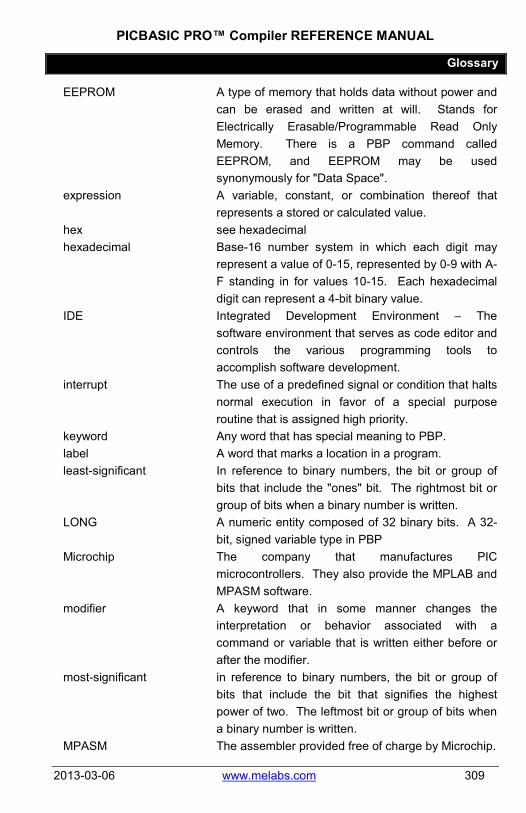
PICBASIC PRO™ Compiler REFERENCE MANUAL
Glossary
2013-03-06 www.melabs.com 309
EEPROM A type of memory that holds data without power and can be erased and written at will. Stands for Electrically Erasable/Programmable Read Only Memory. There is a PBP command called EEPROM, and EEPROM may be used synonymously for "Data Space".
expression A variable, constant, or combination thereof that represents a stored or calculated value.
hex see hexadecimal hexadecimal Base-16 number system in which each digit may
represent a value of 0-15, represented by 0-9 with A-F standing in for values 10-15. Each hexadecimal digit can represent a 4-bit binary value.
IDE Integrated Development Environment – The software environment that serves as code editor and controls the various programming tools to accomplish software development.
interrupt The use of a predefined signal or condition that halts normal execution in favor of a special purpose routine that is assigned high priority.
keyword Any word that has special meaning to PBP. label A word that marks a location in a program. least-significant In reference to binary numbers, the bit or group of
bits that include the "ones" bit. The rightmost bit or group of bits when a binary number is written.
LONG A numeric entity composed of 32 binary bits. A 32-bit, signed variable type in PBP
Microchip The company that manufactures PIC microcontrollers. They also provide the MPLAB and MPASM software.
modifier A keyword that in some manner changes the interpretation or behavior associated with a command or variable that is written either before or after the modifier.
most-significant in reference to binary numbers, the bit or group of bits that include the bit that signifies the highest power of two. The leftmost bit or group of bits when a binary number is written.
MPASM The assembler provided free of charge by Microchip.

PICBASIC PRO™ Compiler REFERENCE MANUAL
Glossary
310 www.melabs.com 2013-03-06
MPASMWIN see MPASM MPASMX see MPASM MPLAB Software application provided free of charge by
Microchip for PIC MCU development. MPLAB includes MPASM, which allows Assembly Language development. High-level languages such as PBP can be installed in MPLAB. MPLAB also serves as the control interface for Microchip's device programmers and debuggers.
nibble A 4-bit binary quantity, most often used to refer to the most-significant or least-significant 4-bits of an 8-bit BYTE. A single hexadecimal digit represents one nibble of binary. Not a variable type in PBP.
overflow The event taking place when a value in a variable is increased beyond the capacity of the variable type, resulting in an incorrect result.
PBPL PBP in LONG mode. Only available for devices with prefix PIC18. When used, LONG variables are available and some commands and operators may work differently than in PBPW.
PBPW PBP in WORD mode. When used, LONG variables are not available and some commands and operators may work differently than in PBPL.
PBPX The name of the executable file that invokes PBP. PM The assembler created by microEngineering Labs
and included with PBP. This assembler should be considered obsolete and MPASM should be used instead.
programmer YOU. The person who writes the program. RAM The area of memory in a PIC MCU that is used to
hold variables. Accessing RAM is faster than accessing other memory areas, and values in RAM are lost when power is removed.
register An 8-bit memory location that performs a special function in a microcontroller. Registers (Microchip calls them SFRs) are built into the microcontrollers and their functions are detailed in the datasheet published for the specific device.

PICBASIC PRO™ Compiler REFERENCE MANUAL
Glossary
2013-03-06 www.melabs.com 311
run-time Executed by the microcontroller when the program runs.
SFR Special Function Register – see register signed Capable of representing or processing negative
numbers as well as positive. two's-complement A system that allows negative numbers to be
represented in binary. typecasting Specifying the variable type to the compiler. underflow The event taking when a value in an unsigned
variable is decreased below zero (negative number), or when a signed variable is decreased below its limit value in the negative, resulting in an incorrect result.
unsigned Only capable of representing or processing positive numbers. Negative numbers are invalid in unsigned variables or processes.
variable A name that stands for a value that is stored in RAM and can be read and changed during program execution
WORD A numeric entity composed of 16 binary bits. A 16-bit, unsigned variable type in PBP
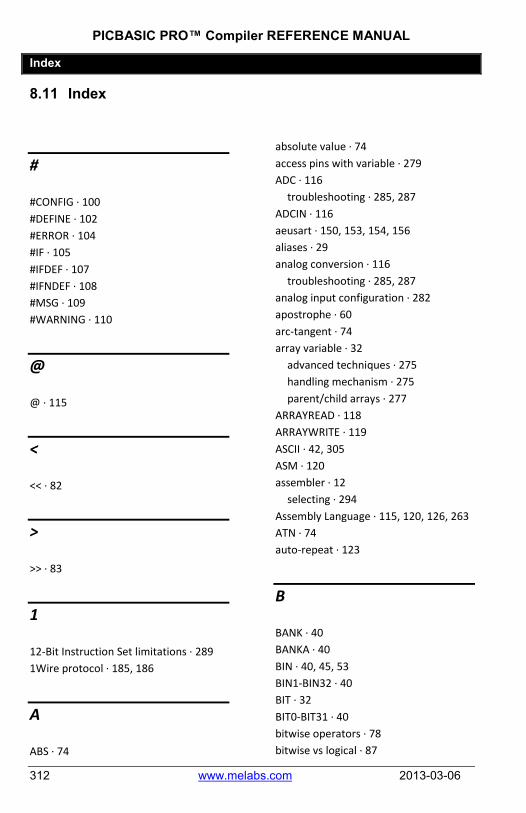
PICBASIC PRO™ Compiler REFERENCE MANUAL
Index
312 www.melabs.com 2013-03-06
8.11 Index
#
#CONFIG · 100 #DEFINE · 102 #ERROR · 104 #IF · 105 #IFDEF · 107 #IFNDEF · 108 #MSG · 109 #WARNING · 110
@
@ · 115
<
<< · 82
>
>> · 83
1
12-Bit Instruction Set limitations · 289 1Wire protocol · 185, 186
A
ABS · 74
absolute value · 74 access pins with variable · 279 ADC · 116
troubleshooting · 285, 287 ADCIN · 116 aeusart · 150, 153, 154, 156 aliases · 29 analog conversion · 116
troubleshooting · 285, 287 analog input configuration · 282 apostrophe · 60 arc-tangent · 74 array variable · 32
advanced techniques · 275 handling mechanism · 275 parent/child arrays · 277
ARRAYREAD · 118 ARRAYWRITE · 119 ASCII · 42, 305 ASM · 120 assembler · 12
selecting · 294 Assembly Language · 115, 120, 126, 263 ATN · 74 auto-repeat · 123
B
BANK · 40 BANKA · 40 BIN · 40, 45, 53 BIN1-BIN32 · 40 BIT · 32 BIT0-BIT31 · 40 bitwise operators · 78 bitwise vs logical · 87

PICBASIC PRO™ Compiler REFERENCE MANUAL
Index
2013-03-06 www.melabs.com 313
Boolean operations · 78 BRANCH · 121 branching · 183 BRANCHL · 122 bs1defs.bas · 295 bs2defs.bas · 295 BUTTON · 123 BYTE · 32 BYTE0-BYTE3 · 40
C
CALL · 126 case sensitivity · 61 CLEAR · 127 CLEARWDT · 128 clock · 26 code page · 266
boundary · 266 code space · 141, 190, 192, 201, 235 command line operation · 290 commands · 112 commands on multiple lines · 64 comment character · 60 comments · 60 comparison · 164 comparison operators · 84 compiler · 12 compile-time constant · 102 compile-time directives · 91 compound conditionals · 87 CON · 39 concatenation · 65 conditional compilation · 91, 105, 107 conditionals · 164
troubleshooting · 287 configuration · 100, 281
for multiple devices · 101 configuration directives · 100
constant · 39 COS · 74 cosine · 74 COUNT · 129 crossing code page boundary · 266 custom compiler messages · 109 customizing error messages · 104, 110
D
DATA · 130 data direction · 23, 166, 184, 205, 284 data space · 130, 139 datasheet · 16 DCD · 74 debounce · 123 DEBUG · 131 debugger · 12
in MPLAB · 270 debugging tips · 281 DEBUGIN · 133 DEC · 40, 44, 51 DEC1-DEC10 · 40 decimal digit · 75 DEFINE · 26, 298
ADC_BITS · 116, 285 ADC_CLOCK · 117, 285 ADC_SAMPLEUS · 117 BUTTON_PAUSE · 123 CCPx_BIT · 148, 287 CCPx_REG · 148, 287 CHAR_PACING · 214 DEBUG_BAUD · 131, 134 DEBUG_BIT · 131 DEBUG_MODE · 131 DEBUG_PACING · 132 DEBUG_REG · 131 DEBUGIN_BIT · 134 DEBUGIN_MODE · 134

PICBASIC PRO™ Compiler REFERENCE MANUAL
Index
314 www.melabs.com 2013-03-06
DEBUGIN_REG · 134 HSER_BAUD · 150, 154 HSER_BITS · 151, 155 HSER_CLROERR · 151 HSER_EVEN · 151, 155 HSER_ODD · 151, 155 HSER_RCSTA · 150, 154 HSER_SPBRG · 150, 154 HSER_SPBRGH · 150, 154 HSER_TXSTA · 150, 154 HSER2_BAUD · 153, 156 HSER2_BITS · 153, 156 HSER2_CLROERR · 153 HSER2_EVEN · 153, 156 HSER2_ODD · 153, 156 HSER2_RCSTA · 153, 156 HSER2_SPBRG · 153, 156 HSER2_SPBRGH · 153, 156 HSER2_TXSTA · 153, 156 I2C_HOLD · 159, 163 I2C_INTERNAL · 159, 162 I2C_SCL · 157, 161 I2C_SCLOUT · 159, 163 I2C_SDA · 157, 161 I2C_SLOW · 159, 162 ICD_USED · 271 INTHAND · 249 INTLHAND · 249 LCD_BITS · 170, 173 LCD_COMMANDUS · 170, 173 LCD_DATAUS · 170, 173 LCD_DBIT · 170, 173 LCD_DREG · 170, 173 LCD_EBIT · 170, 173 LCD_EREG · 170, 173 LCD_LINES · 170, 173 LCD_RSBIT · 170, 173 LCD_RSREG · 170, 173 LCD_RWBIT · 167 LCD_RWREG · 167
list · 298 NO_CLEAR_STKPTR · 203 NO_CLRWDT · 128 OSC · 26, 281 OSCCAL_1K · 283 SER2_BITS · 210, 217 SER2_ODD · 210, 216 SHIFT_PAUSEUS · 221, 223 WRITE_INT · 234, 236 XINXLAT_OFF · 238 XOUTXLAT_OFF · 240
delay · 187, 188 device configuration · 100, 281
for multiple devices · 101 device families · 17 device prefix · 17 device programmer · 12 directives · 91 DISABLE · 92, 244 DISABLE DEBUG · 93 DISABLE INTERRUPT · 94 display · 167, 168 division · 73, 75 DO · 136 DTMF tones · 138 DTMFOUT · 138 duty cycle · 148
E
editing programs · 14 eeprom · 130, 139 EEPROM · 139 ELSE · 164 ELSEIF · 164 ENABLE · 95, 244 ENABLE DEBUG · 96 ENABLE INTERRUPT · 97 END · 140

PICBASIC PRO™ Compiler REFERENCE MANUAL
Index
2013-03-06 www.melabs.com 315
ENDASM · 120 ENDIF · 164 environment variables · 294 ERASECODE · 141 eusart · 150, 153, 154, 156 EXIT · 142
F
FOR..NEXT · 143 formatting strings · 51 FREQOUT · 144 frequency generation · 144 frequency measurement · 129
G
generating compile errors · 104 generating compiler messages · 109 generating compiler warnings · 110 glossary · 307 GOSUB · 145 GOTO · 146
H
hardware stack · 273 HEX · 40, 46, 54 HEX1-HEX8 · 40 hierarchal order · 70, 287 HIGH · 147 home automation · 237, 239 HPWM · 148 HSERIN · 150 HSERIN2 · 153 HSEROUT · 154 HSEROUT2 · 156
HYP · 76 hypotenuse · 76
I
I/O pins · 23 characteristics · 25
I2C · 157, 161 I2CREAD · 157 I2CWRITE · 161 IBIN · 40 ICD · 12 IDE · 12, 14 IF..THEN · 164 INCLUDE · 66 index value · 37 INPUT · 166 input pins · 23, 166, 205
characteristics · 25 troubleshooting · 282, 284, 286
instruction set · 17 Integrated Development Environment ·
12, 14 internal oscillator · 282 interrupts · 203, 244
14-Bit Instruction Set · 257 associated DEFINEs · 249 Enhanced 14-Bit Instruction Set · 256 in Assembly Language · 248 in BASIC · 244 latency concerns · 246 PIC18 · 252 priority in PIC18 · 252
interrupts in BASIC · 99 intializing variables · 127

PICBASIC PRO™ Compiler REFERENCE MANUAL
Index
316 www.melabs.com 2013-03-06
J
jump to label · 146
L
labels · 31 latency · 246 lcd · 167, 168 LCDIN · 167 LCDOUT · 168 LET · 174 limiting values · 76 line extension · 64 logical operators · 87 logical vs bitwise · 87 LONG · 32, 41 LOOKDOWN · 175 LOOKDOWN2 · 176 LOOKUP · 177, 178 lookup table · 177, 178, 192 LOOP · 136 LOW · 179 low-power mode · 180, 224
M
MAX · 76 measuring pulse width · 195, 199 melabs · 19 MicroCode Studio · 14 microsecond delay · 188 millisecond delay · 187 MIN · 76 modedefs.bas · 295 modifiers · 33 MPLAB · 14, 270
multiple commands on line · 65 multiplication · 71 multiplying fractions · 72
N
NAP · 180 NCD · 77 nesting GOSUBs · 273 non-volatile memory · 139 number formats · 58
O
ON DEBUG · 98 ON GOSUB · 182 ON GOTO · 183 ON INTERRUPT · 99, 244 operators · 67
* · 71 ** · 72 */ · 72 / · 73 // · 73 ABS · 74 ATN · 74 bitwise · 78 Boolean · 78 comparison · 84 cosine · 74 DCD · 74 DIG · 75 DIV32 · 75 division · 73 HYP · 76 logical · 87 math · 71 MAX · 76

PICBASIC PRO™ Compiler REFERENCE MANUAL
Index
2013-03-06 www.melabs.com 317
MIN · 76 modulus · 73 multiplication · 71 NCD · 77 remainder · 73 REV · 77 SIN · 77
oscillator · 26 internal · 282
OUTPUT · 184 output pins · 23, 147, 179, 184, 205, 228
characteristics · 25 troubleshooting · 283, 284, 286
overrunning arrays · 275 overview of commands · 112 OWIN · 185 OWOUT · 186
P
parsing strings · 44 PAUSE · 187 PAUSEUS · 188 PBPL · 15 PBPW · 15 PEEK · 189 PEEKCODE · 190 POKE · 191 POKECODE · 192 POT · 193 potentiometer · 116, 193 preprocessor directives · 91 program memory · 141, 190, 192, 201,
235 program organization · 22 programmer · 12 pulse width modulation · 197 PULSIN · 195 PULSOUT · 196
pushbutton input · 123 pwm · 148, 197 PWM · 197
R
RAM allocation · 268 RAM bank · 266 RANDOM · 198 RCTIME · 199 READ · 200 READCODE · 201 reading voltage · 116 Read-Modify-Write · 283 registers · 16, 59 remainder · 73 REP · 40, 56 REPEAT..UNTIL · 202 reserved words · 301 RESUME · 203, 244 RETURN · 204 REV · 77 REVERSE · 205 reversing bits · 77 RMW · See Read-Modify-Write RS-232 · 131, 133, 207, 209, 213, 215
S
SBIN · 40 scalar variable · 32 SDEC · 40 SELECT CASE · 206 selecting assembler · 294 semicolon · 60 serial communication · 131, 133, 150,
153, 154, 156, 207, 209, 213, 215 SERIN · 207
PICBASIC PRO™ Compiler REFERENCE MANUAL
Index
318 www.melabs.com 2013-03-06
SERIN2 · 209 modes · 296
SEROUT · 213 SEROUT2 · 215
modes · 296 SFRs · 16, 59 shift left · 82 shift right · 83 SHIFTIN · 219 SHIFTOUT · 222 SIN · 77 sine · 77 SKIP · 40, 47 sleep · 180, 224 SLEEP · 224 SOUND · 225 spaces · 62 SPI · 219, 222 SQR · 77 square root · 77 stack · 273 STOP · 226 STR · 40, 47, 56 strings · 42
formatting · 51, 119 in arrays · 118, 119 parsing · 44, 118
subroutines · 145, 204 SWAP · 227 synchronous serial · 219, 222 syntax · 22 SYSTEM · 40 system clock · 26 system overview · 12
T
table lookup · 177, 178, 192 tabs · 62
technical support · 20 terminating loops · 142 timed pulse · 196 timing accuracy · 26 TOGGLE · 228 troubleshooting · 281 twos-complement · 39, 74
U
underscore · 64 UNTIL · 136 usart · 150, 153, 154, 156 USB · 229, 230, 231, 232 USBIN · 229 USBINIT · 230 USBOUT · 231 USBSERVICE · 232
V
variable modifiers · 36 variable to specify pin · 279 variables · 32
initializing · 127, 281 placement in memory · 268
W
WAIT · 40, 48 WAITSTR · 40, 49 watchdog timer · 128 WHILE · 136 WHILE..WEND · 233 white space · 62 WORD · 32, 41 WORD0-WORD1 · 40
PICBASIC PRO™ Compiler REFERENCE MANUAL
Index
2013-03-06 www.melabs.com 319
WRITE · 234 WRITECODE · 235
X
X-10 · 237, 239 XIN · 237 XOUT · 239