pic18f to pic24f migration: an overvie · both pic18f and pic24f devices include a dedicated...
TRANSCRIPT

© 2006 Microchip Technology Inc. DS39764A-page 1
INTRODUCTION
The PIC24F architecture specification was created asa powerful extension of Microchip’s existing RISCmicrocontroller portfolio. By giving users an evengreater range of options for computational power andrich peripheral sets, it allows users to grow their appli-cations. At the same time, the architecture was tailoredto keep as much of the existing PICmicro® MCU featureset and nomenclature as possible, making it easy forapplications to make the jump.
This migration document highlights the similarities anddifferences between the PIC18F and PIC24F devicefamilies, and shows the general principles for migratingPIC18F applications to PIC24F devices. Throughoutthis document, it is assumed that the application to beported is based on a member of one of the later PIC18Fdevice families, such as the popular PIC18F8722family, with a complete feature set and the latestversion of nanoWatt Technology of all PIC18F devices.The target device is assumed to be in thePIC24FJ128GA general purpose family, which is thefirst generation of PIC24F general purpose devices.However, the general guidelines represented here canbe applied to migrating any PIC18F device-basedapplication to a PIC24F platform.
To present such a comprehensive overview, it wasdecided to divide the material into two major sections,each with a slightly different approach. The first sectioncompares and contrasts the core architectural differ-ences between the families, highlighting the majordifferences. Because the changes can greatly changethe overall structure of an application, the focus is noton how to do specific tasks, but what larger changesneed to be considered in migration. The specific modi-fications required are left to the user’s professionaljudgment.
The second section discusses the peripherals thatPIC18F and PIC24F architectures have in common.Like the core, module features are compared. Here, itis possible to also compare the steps needed to makeeach module run and give task-specific information.Only those peripheral features that are available in botharchitectures are presented here.
Users are encouraged to review the PIC24F devicedata sheets for information on the new modules, andhow they may be used in applications that arecandidates for migration.
Contents
PIC24F Core Architecture .......................................... 2CPU Core............................................................ 2
Instruction Set ..................................................... 4Memory Map and Program Memory ................... 7Data Memory Space ......................................... 11
Resets and Start-up Timing............................... 13Interrupt Controller ............................................ 17Oscillator ........................................................... 19
Power-Saving Features .................................... 23Watchdog Timer (WDT) .................................... 25Device Integration Features.............................. 26
PIC24F Peripheral Set ............................................. 27I/O Ports............................................................ 27Timers (Timer1, Timer2/3 and Timer4/5)........... 29
Capture/Compare/PWM (CCP and ECCP)....... 31Serial Peripheral Interface (SPI) ....................... 34Inter-Intergrated Circuit™ (I2C™)..................... 36
Universal Asynchronous Receiver/Transmitter (UART)............................ 38
10-Bit A/D Converter......................................... 41Comparator and Comparator VoltageReference Modules........................................... 43
Summary.................................................................. 45
References............................................................... 45
Mapping PIC18F to PIC24F Instructions.................. 47
Note 1: This device has been designed toperform to the parameters of its datasheet. It has been tested to an electricalspecification designed to determine itsconformance with these parameters. Dueto process differences in the manufactureof this device, this device may have differ-ent performance characteristics than itsearlier version. These differences maycause this device to perform differently inyour application than the earlier version ofthis device.
2: The user should verify that the deviceoscillator starts and performs asexpected. Adjusting the loading capacitorvalues and/or the oscillator mode may berequired.
PIC18F to PIC24F Migration: An Overview

DS39764A-page 2 © 2006 Microchip Technology Inc.
PIC24F CORE ARCHITECTURE
CPU Core
Aside from its 16-bit data size, the PIC24F architectureis significantly different from the PIC18F architecture.The instruction word size, instruction clocking scheme,
stack implementation and core registers are verydifferent from PIC18F implementations. Other hard-ware features have been added to enhance processingperformance. Changes are summarized in Table 1.
TABLE 1: COMPARISON OF PIC18F AND PIC24F CPU CORE FEATURES
INSTRUCTION SIZE
All PIC18F devices use a 16-bit (single-word) instruc-tion. PIC24F devices use a 24-bit instruction. A moredetailed discussion on instructions is presented in the“Instruction Set” section.
INSTRUCTION CLOCKING
PICmicro microcontrollers execute instructions at a ratethat is a simple fraction of the clock speed, designatedas TCY. For the most part, PIC18F and PIC24F devicesperform most instructions with a fetch step and an
execution step of 1 TCY each. For PIC18F devices, eachTCY interval represents 4 clock cycles, with the PC beingincremented on falling edges. In contrast, the TCY forPIC24F devices is 2 clock cycles, with the PC beingincremented on leading clock edges. The differences ininstruction pipelining are shown in Figure 1. Thisdifference in instruction execution is one of the biggestdifferences between the two architectures, and needs tobe taken into consideration for any peripherals that usethe instruction clock speed as a base for their timing.
FIGURE 1: COMPARISON OF PIC18F AND PIC24F INSTRUCTION EXECUTION PIPELINES
Feature PIC18F PIC24F
Instruction Size 16 bits 24 bits
Instruction Clocking TCY = FOSC/4 TCY = FOSC/2
Working Registers 1 (W, WREG) 16 (W0-W15)
Status Registers One (STATUS) Two (STATUS and CORCON)
Stack Hardware, 31 levels Software
Hardware Multiplier 8 x 8 17 x 17
Hardware Divider No Hardware assisted division using DIV and REPEAT
Bit Shifting/Rotation Single bit, left or right, rotation only Barrel shifting up to 15 bits, left or right, shift or rotate
Program Space Visibility (PSV)
No Yes
Device Clock
PIC18F Program Counter
PIC18F Execution Pipeline
PC PC + 2 PC + 4 PC + 6 PC + 8
Fetch PC – 2 Execute PC – 2Fetch PC Execute PC
Fetch PC + 2 Execute PC + 2Fetch PC + 4 Execute PC + 4
Fetch PC + 6 Execute PC + 6Fetch PC + 8
PIC24F Execution Pipeline
PIC24F Program Counter PC – 2
PC
Fetch INST (PC)Execute INST (PC – 2)
PC + 2
Fetch INST (PC + 2)Execute INST (PC)
PC + 4
Fetch INST (PC + 4)Execute INST (PC + 2)
© 2006 Microchip Technology Inc. DS39764A-page 3
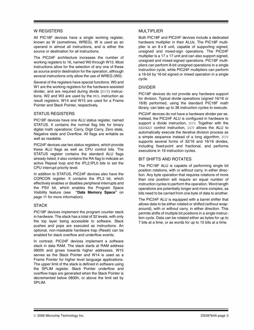
W REGISTERS
All PIC18F devices have a single working register,known as W (sometimes, WREG). W is used as anoperand in almost all instructions, and is either thesource or destination for all instructions.
The PIC24F architecture increases the number ofworking registers to 16, named W0 through W15. Mostinstructions allow for the selection of any one of theseas source and/or destination for the operation, althoughseveral instructions only allow the use of WREG (W0).
Several of the registers have special functions. W0 andW1 are the working registers for the hardware-assisteddivider, and are required during divide (DIV) instruc-tions. W2 and W3 are used by the MUL instruction asresult registers. W14 and W15 are used for a FramePointer and Stack Pointer, respectively.
STATUS REGISTERS
PIC18F devices have one ALU status register, namedSTATUS. It contains the normal flag bits for binarydigital math operations: Carry, Digit Carry, Zero state,Negative state and Overflow. All flags are writable aswell as readable.
PIC24F devices use two status registers, which providethese ALU flags as well as CPU control bits. TheSTATUS register contains the standard ALU flagsalready listed; it also contains the RA flag to indicate anactive Repeat loop and the IPL2:IPL0 bits to set theCPU interrupt priority level.
In addition to STATUS, PIC24F devices also have theCORCON register. It contains the IPL3 bit, whicheffectively enables or disables peripheral interrupts andthe PSV bit, which enables the Program SpaceVisibility feature (see “Data Memory Space” onpage 11 for more information).
STACK
PIC18F devices implement the program counter stackin hardware. The stack has a total of 32 levels, with onlythe top layer being accessible to software. Stackpushes and pops are executed as instructions. Anoptional, non-maskable hardware trap (Reset) can beenabled for stack overflow and underflow events.
In contrast, PIC24F devices implement a softwarestack in data RAM. The stack starts at RAM address0800h and grows towards higher addresses. W15serves as the Stack Pointer and W14 is used as aFrame Pointer for higher level language applications.The upper limit of the stack is defined in software usingthe SPLIM register. Stack Pointer underflow andoverflow traps are generated when the Stack Pointer isdecremented below 0800h, or above the limit set bySPLIM.
MULTIPLIER
Both PIC18F and PIC24F devices include a dedicatedhardware multiplier in their ALUs. The PIC18F multi-plier is an 8 x 8 unit, capable of supporting signed,unsigned and mixed-sign operations. The PIC24Fmultiplier is a 17 x 17 unit and can also support signed,unsigned and mixed-signed operations. PIC18F multi-pliers can perform 8-bit unsigned operations in a singleinstruction cycle, while PIC24F multipliers can performa 16-bit by 16-bit signed or mixed operation in a singlecycle.
DIVIDER
PIC18F devices do not provide any hardware supportfor division. Typical divide operations (signed 16/16 or16/8) performed, using the standard PIC18F mathlibrary, can take up to 38 instruction cycles to execute.
PIC24F devices do not have a hardware divider per se.Instead, the PIC24F ALU is configured in hardware tosupport a divide instruction, DIV. Together with theREPEAT control instruction, DIV allows the ALU toautomatically execute the iterative division process asa simple sequence instead of a long algorithm. DIVsupports several forms of 32/16 and 16/16 divides,including fixed-point and fractional, and performsexecutions in 19 instruction cycles.
BIT SHIFTS AND ROTATES
The PIC18F ALU is capable of performing single bitposition rotations, with or without carry, in either direc-tion. Any byte operation that requires rotations of morethan one position will require an equal number ofinstruction cycles to perform the operation. Word lengthoperations are potentially longer and more complex, asbits need to be carried from one byte of data to another.
The PIC24F ALU is equipped with a barrel shifter thatallows data to be either rotated or shifted (without wrap-around), with or without carry, in either direction. Thispermits shifts of multiple bit positions in a single instruc-tion cycle. Data can be rotated either as bytes for up to7 bits at a time, or as words for up to 15 bits at a time.

DS39764A-page 4 © 2006 Microchip Technology Inc.
Instruction Set
The PIC24F instruction set architecture represents aconsiderable extension of its PIC18F predecessor.While barely larger in terms of base instructions, itmakes substitutions of selected instructions toenhance the performance, while expanding the scope
of addressing modes and data type operations.Through all of this, the PIC24F instruction set maintainsthe highly orthogonal structure of previous PICmicroarchitectures.
The main differences between the PIC18F and PIC24Finstruction sets are presented in Table 2.
TABLE 2: COMPARISON OF MAJOR INSTRUCTION SET FEATURES
CHANGES FROM PIC18F INSTRUCTION SET
The PIC24F instruction set implements severalfeatures that enhance performance for math opera-tions, and extend the ability to handle high-levellanguages with more complex stack and pointerrequirements. These are summarized in Table 3.
In addition, several PIC18F instructions do not have anexact single instruction equivalent in the PIC24F archi-tecture. Most of these instructions have either single orpairs of PIC24F instructions that have similar effect, butbecause of differences in the STATUS register, resultsare not exactly equivalent. They are:
Even with these changes, most PIC18F assemblerinstructions have a single-cycle equivalent in thePIC24F assembler. A comprehensive list is providedin Appendix A: “Mapping PIC18F to PIC24FInstructions”.
TABLE 3: NEW OR SIGNIFICANTLY MODIFIED PIC24F INSTRUCTIONS
Feature PIC18F PIC24F
Instruction Size 16 bits 24 bits
Base Instructions 75 76
Supported Data Types Byte Byte, Word, Double Word
Operand Support Up to binary (b = a + b) Up to trinary (a + b = c)
Addressing Modes Direct, Indirect (5) Direct, Indirect (6)
Indirect Addressing Type Uses FSR Pointer register sets; limit of 3 pointers
Uses any of the W registers as pointers with instruction-based manipulation; limit of 16
Data Space Addressing Short literal, limited to a single bank at one time; full literal on few instructions
Short literal for entire Near Data Space; indirect address for entire space
• CPFSEQ • INFSNZ
• CPFSGT • MOVSF
• CPFSLT • MOVSS
• DCFSNZ • PUSHL
• DECFSZ • SUBULNK
• INCFSZ • TSTFSZ
• MOVFF (all modes except indirect to indirect)
• SWAPF (all modes except with WREG)
PIC24F Instruction Description
DIV Divide two numbers (signed or unsigned, 16/16 or 32/16)
LNK and UNLK Link or unlink Frame Pointer (W14)
LSR and ASR Logical or arithmetic shift right by 1 to 16 bits, by either a literal or variable value
MUL.SS, MUL.SU, MUL.US
Specific instructions for multiplying signed and unsigned numbers
PUSH and POP Both instructions now include source or destination arguments, allowing the stack to store values other then the current PC
REPEAT Repeat the next instruction a specified number of times
SL Shift left by 1 to 16 bits by either a literal or variable value

© 2006 Microchip Technology Inc. DS39764A-page 5
SUPPORTED DATA TYPES
Aside from bit-oriented instructions, PIC18Finstructions operate exclusively on single byte data.Any data that is longer than a single byte is handled byconcatenating bytes in the proper order.
As 16-bit devices, PIC24F instructions are designed tohandle data in terms of 16-bit words. In addition, mostinstructions are capable of handling single byte anddouble word (32-bit) data objects. Invoking this featureis generally done by using the suffix “.b” (for bytes) or“.d” (for double words) after the instruction mnemonic.Data alignment within the memory space is automati-cally adjusted and maintained according to the datatype selected.
OPERAND SUPPORT
The PIC18F instruction set supports both unary andbinary operations. That is to say, an instruction canfunction with a single argument operating on the con-tents of one register (e.g., increment the WREG), orwith two arguments storing the results in one of the tworegisters (e.g., adding the contents of a register toWREG and storing the sum in WREG).
The PIC24F instruction set also supports trinaryoperations; that is, an operation can have three argu-ments, specifying not only two operands but also anindependent address for the result. Trinary operationsare supported for most arithmetic and logic instructions.
ADDRESSING MODES
The biggest difference between the PIC18F andPIC24F instruction sets is how the instructions specifyaddresses in the data memory space. While the meth-ods are equivalent, the PIC24F version allows moreoptions for more of its instructions.
Direct Addressing
While PIC18F instructions can directly address anyregister in the data space, very few specify a fulladdress as part of the instruction. Instead, most use an8-bit literal value to specify an address within one of16 banks of 256 bytes within the space. The bank inquestion is separately selected by the Bank SelectRegister (BSR).
PIC24F instructions are designed to be able to literallyaddress any register within the lowest 8 Kbytes of thedata space (also known as the Near Data Space). Thisallows immediate access to all SFRs. Implementedmemory areas above the top of the Near Data Spaceare accessible by indirect addressing, as describedbelow.
Indirect Addressing
PIC18F instructions perform indirect addressingthrough pointers and virtual registers. Three 12-bitpointers (FSR0 through FSR2) are loaded withappropriate values; then, one of five virtual registersassociated with that pointer is used as an argument foran instruction, either as an address or an offset for anaddress. Depending on which of the registers is used,the value of the pointer can also be automatically incre-mented or decremented. Only these three pointers andtheir associated registers can be used for indirectaddressing.
In contrast, PIC24F architecture increases the numberof options for the addressing mode. Any one of the Wregisters can be used as a pointer for indirect address-ing. Instead of using a virtual register name to determinethe pointer and its operation, the MPLAB® IDEassembler language uses specific syntax conventionsto indicate when a W register is being used as a pointeror offset, and what increment or decrement operation isto be done to the register. The PIC24F Instruction SetArchitecture (ISA) also offers a pre-decrement optionnot available with PIC18F. An additional feature of thePIC24F increment/decrement options is how they workwith the data type specified by the instruction. If theinstruction is executed as a byte type instruction, theregister will be incremented or decremented by one.This aligns the pointer to the next byte in memory whichis not always the next memory address. Word-orientedinstructions will increment or decrement the register bytwo and maintain proper word alignment.
The differences between architectures in indirectaddressing modes and syntax are summarized inTable 4. A comparison of how to use these addressingmodes is shown in Example 1.
TABLE 4: INDIRECT ADDRESSING IN PIC18F AND PIC24F INSTRUCTION SETS
Indirect Addressing Mode
PIC18F Virtual Register Operand
PIC24F Equivalent Syntax
Wn (or FSR)
After Byte Instruction
After Word Instruction
No Modification INDFx [Wn] Wn = Wn Wn = Wn
Pre-Increment PREINCx [++Wn] Wn = Wn + 1 Wn = Wn + 2
Pre-Decrement N/A [--Wn] Wn = Wn – 1 Wn = Wn – 2
Post-Increment POSTINCx [Wn++] Wn = Wn + 1 Wn = Wn + 2
Post-Decrement POSTDECx [Wn--] Wn = Wn – 1 Wn = Wn – 2
Register Offset PLUSWx [Wn + Wb] Wn = Wn Wn = Wn

DS39764A-page 6 © 2006 Microchip Technology Inc.
EXAMPLE 1: COMPARISON OF INDIRECT ADDRESSING TECHNIQUES
RAW Dependencies
The increased flexibility in addressing modes creates afew situations where Read-After-Write (or RAW)dependencies may be created. RAW dependenciesexist when a variable needed for an instruction that isbeing fetched stage has not been written back to theregister yet. These occur only in select situations,
generally when a register used as a destination for oneinstruction is also an argument in an immediatelyfollowing instruction, and are listed in Table 5. ThePIC24F CPU core includes “look ahead” detection forthese RAW hazards, and introduces one or more stall(NOP) cycles between instructions to avoid executionerrors.
TABLE 5: SUMMARY OF READ-AFTER-WRITE DEPENDENCY RULES
Typical PIC18F Code Sequence:LoopSetup MOVLW 0x10, LoopCount ;set up loop counter
LFSR 0, myArray0 ;set up pointer 0LFSR 1, myArray1 ;set up pointer 1
CopyLoop MOVFF POSTINC0, POSTINC1 ;copy myArray1 to myArray0DECFSZ LoopCount, F ;decrement loop counterBRA CopyLoop ;loop
Equivalent PIC24F Code Sequence:LoopSetup MOV #myArray0, W0 ;set up pointer 0
MOV #myArray1, W1 ;set up pointer 1CopyLoop REPEAT #15 ;loop 16 times
MOV [W1++], [W0++] ;copy array1 to array
Destination Addressing Mode
Using Wn
Source Addressing Mode
Using Wn
Required Stall(CPU cycles added to instruction time)
Examples(Wn = W2)
Direct Direct None ADD.w W0, W1, W2MOV.w W2, W3
Indirect Direct None ADD.w W0, W1, [W2]MOV.w W2, W3
Indirect Indirect None ADD.w W0, W1, [W2]MOV.w [W2], W3
Indirect Indirect with pre/post-modification
None ADD.w W0, W1, [W2]MOV.w [W2++], W3
Indirect with pre/post-modification
Direct None ADD.w W0, W1, [W2++]MOV.w W2, W3
Direct Indirect 1 ADD.w W0, W1, W2MOV.w [W2], W3
Direct Indirect with pre/post-modification
1 ADD.w W0, W1, W2MOV.w [W2++], W3
Indirect Indirect 1 ADD.w W0, W1, [W2]MOV.w [W2], W3; W2=04h (mapped W2)
Indirect Indirect with pre/post-modification
1 ADD.w W0, W1, [W2]MOV.w [W2++], W3; W2=04h (mapped W2)
Indirect with pre/post-modification
Indirect 1 ADD.w W0, W1, [W2++]MOV.w [W2], W3
Indirect with pre/post-modification
Indirect with pre/post-modification
1 ADD.w W0, W1, [W2++]MOV.w [W2++], W3

© 2006 Microchip Technology Inc. DS39764A-page 7
Memory Map and Program Memory
Both PIC18F and PIC24F architectures use the samegeneral schema for their program memory spaces.Aside from the self-evident differences in width,PIC24F devices also incorporate a larger addressingrange and enhanced visibility features in data space.
The organization of the space and the location ofnon-program memory features also differ somewhat,and must be considered when porting an application.
The key differences between the memory organizationof PIC18F and PIC24F devices are presented inTable 6.
TABLE 6: COMPARISON OF PIC18F AND PIC24F PROGRAM MEMORY ARCHITECTURES
ORGANIZATION
The PIC18F program space is organized as 16-bitwords, but is addressable in terms of bytes. Thismeans that the upper or lower byte of any word can beindividually addressed by a pointer. To maintain wordalignment for code execution, the memory space isaligned on the Least Significant Byte (LSB) of eachword, and the program counter increments by 2 duringnormal execution.
The PIC24F program space has a different, but parallelstructure. It is physically organized as 24 bits wide, butis addressed as 16-bit words. Thus, an instruction isconsidered to be two words, not 3 bytes. Each wordcan be individually addressed with even addressesrepresenting the lower word of an instruction and oddaddresses the upper word. To maintain instructionalignment, the memory space is aligned on evenwords; the program counter increments by 2 duringnormal execution.
Since a PIC24F instruction is three bytes wide, theMost Significant Byte of an instruction finds itself alonein the most significant word of the instruction as it isstored in memory. To maintain word alignment whenreading from, or writing to program memory, a“phantom byte” of 00h is added before the MSB to giveit the proper word length (Figure 2). The value reflectsthat this byte is not actually implemented in physicalprogram memory.
Even with its word-aligned addressing, any single bytewithin the program space can be individually read orwritten. The PIC24F TBLRD and TBLWT commands areextended to allow an individual upper or lower byte ofany word to be accessed. Keep in mind that the upperbyte of any upper word (odd address) will always be00h, and cannot be written to, for reasons previouslydiscussed.
FIGURE 2: PIC24F PROGRAM MEMORY ORGANIZATION
Feature PIC18F PIC24F
Organization 16-bit, byte addressable 24-bit, word addressable
Total Addressable Range 4 Mbytes (22-bit magnitude) 16 Mbytes (24-bit magnitude)
Maximum Available User Program Space (upper boundary address)
2 Mbytes (FFFFFh) 8 Mbytes (7FFFFFh)
Boot Block Support Most devices No
Interrupt/Reset/Trap Vectors 00h, 08h, 18h 00h to 1FFh
Configuration Word Locations 300000h to 30000Fh Last 2 implemented locations in program memory
Device ID Locations 3FFFFE and 3FFFFFh FF0000h and FF0002h
0816
PC Address
000000h000002h
000004h000006h
2300000000
00000000
00000000
00000000
Program Memory‘Phantom’ Byte
(read as ‘0’)
Least Significant WordMost Significant Word
Instruction Width
000001h000003h
000005h000007h
MSWAddress (LSW Address)

DS39764A-page 8 © 2006 Microchip Technology Inc.
ADDRESSABLE AND USER-AVAILABLE RANGE
Both architectures base the size of their program spaceentirely on the size of the program counter. PIC18Fdevices use a 22-bit program counter for a totaladdressable space of 4 Mbytes. PIC24F devices use a24-bit counter for a total range of 16 Mbytes.
In addition, both architectures reserve the upper half ofthe addressable program space as “configurationspace”; this is largely unimplemented addresses, with
several implemented areas for device configuration,identification and programming. Thus, the total maxi-mum available space for program memory is 2 Mbytesfor PIC18F devices, and 8 Mbytes for PIC24F devices.It is worth noting that no device in either family entirelyimplements the full available range of program memoryspace.
The program spaces for the two architectures areshown in comparison in Figure 3.
FIGURE 3: COMPARISON OF PIC18F AND PIC24F PROGRAM MEMORY SPACES(1)
000000h
0000FEh
000002h
000100h
800000h
FEFFFEhFF0000h
FFFFFFh
000004h
7FFFFEh
000200h0001FEh000104h
Reset Address
User FlashProgram Memory
(up to 128K words)
DEVID (2)
Unimplemented
(Read ‘0’s)
GOTO Instruction
Reserved
Alternate Vector Table
Reserved
Interrupt Vector Table
PIC24F Family
Device Config Words(Top of PM)-4
Note 1: Memory areas are not shown to scale. Scales differ for PIC18F and PIC24F maps.
2: Only the elements of program space common to all PIC18F devices are shown. Later features, such as BootBlocks and Flash Configuration Words (PIC18FXXJ Flash devices only) have been omitted for clarity.
Device Configuration
User FlashProgram Memory
(up to 128 Kbytes)
Registers
DEVID (2)
Unimplemented
(Read ‘0’s)
Reset Vector
Reserved
Reserved
Low/High Interrupt Vectors
000000h
000008h000018h
200000h
300000h
30000Fh300010h
3FFFFEh3FFFFFh
2FFFFFh
1FFFFEh
PIC18F Family(2)
(Top of PM)(Top of PM)
Program Memory Area
Configuration Space

© 2006 Microchip Technology Inc. DS39764A-page 9
INTERRUPT/RESET/TRAP VECTORS
In PIC18F devices, three addresses at the bottom ofprogram memory are reserved for hardware vectors.Application code for these devices places destinationaddresses for hardware Resets, high-level InterruptService Routines (ISRs) and low-level ISRs in 00h, 08hand 18h, respectively.
In PIC24F devices, the reserved range is much larger:from 00h to 1FFh. Location 00h is still reserved for thehardware Reset vector. Addresses 06h through FFhare reserved for the main interrupt vector table, whichcontains 118 separate hardware address vectors(including 8 non-maskable hardware traps). Addresses100h through 1FFh contain an alternate interrupt vectortable, also of 118 hardware address vectors, that isreserved for use in Emulation mode.
CONFIGURATION WORDS AND DEVICE IDS
Both PIC18F and PIC24F devices locate their factorydevice IDs in the configuration space above the programmemory area. PIC18F Configuration registers are alsolocated in configuration space, whereas PIC24F Config-uration registers are located in program memory.PIC18F devices locate their Configuration Words at300000h through 30000Fh, and device IDs at 3FFFFEhand 3FFFFFh. PIC24F devices locate their Configura-tion Words at the last two addresses in implementedprogram memory, and device IDs at FF0000h andFF0002h.
BOOT BLOCK SUPPORT
Many PIC18F devices allow users to reserve andindependently code-protect a small area at the base ofthe user program space (depending on the device,between 1 and 4K words) for an independentbootloader program.
As of this writing, a similar feature is not implementedin PIC24F devices. This absence does not rule out theuse of bootloader programs; it only means that a dedi-cated and separately protectable block of programmemory is not available.
EXTERNAL MEMORY MAPPING
The PIC18F architecture supports the use of externalmemory devices as program memory. This feature,known as the External Memory Interface (EMI), isactually implemented as part of the CPU core’s addressbus management system. The EMI allows the programaddress bus to address and retrieve data from off-chipdevices as if they were part of the 2 Mbyte, on-chip pro-gram space. Multiple operating modes are implemented,such as using off-chip memory exclusively as programmemory. Because of the I/O requirements, the EMI isonly available on PIC18F devices with 80 or more pins.
As of this writing, PIC24F devices do not offer thisfeature. Program size is limited to that of on-chipmemory.
FLASH MEMORY OPERATION
Many PIC18F and PIC24F devices use self-programmable Flash technologies to implementprogram memory. The general schema of memoryoperations and how they are performed are verysimilar, such as:
• the ability to self-program some or all of the Flash memory during run time
• the ability to program or reprogram a device already embedded in the application through a 5-wire serial interface (In-Circuit Serial Programming™ or ICSP™), or during device operation (Enhanced In-Circuit Serial Programming or EICSP)
• the use of erase and write blocks of defined sizes, and erase-before-write programming algorithms
• the self-timed write process after filling a write buffer block, which stalls CPU execution for one or more TCY
Only those differences that may impact the migration ofan application are noted here.
Register and Bit Nomenclature
PIC18F and PIC24F devices all use a single controlregister and a single unlock register to control Flashoperations. Some register and bit names, as shown inTable 7, change between the architectures.
TABLE 7: FLASH CONTROL REGISTERS AND BITS IN PIC18F AND PIC24F ARCHITECTURES
The key Flash control bits (WR, WREN and WRERR)have the same names and functions in botharchitectures.
Flash Register or Bit Description
PIC18F PIC24F
Flash Control Register EECON1 NVMCON
Flash Key Register EECON2 NVMKEY
EEPROM Data Register EEPGD —
PM/EEPROM Destination Select bit
CFGS —
Flash Operation Enable bit
FREE ERASE

DS39764A-page 10 © 2006 Microchip Technology Inc.
Flash Addressing
In PIC18F devices, the target address of Flash opera-tions is specified by a 22-bit Table Pointer register,TBLPTR, that is composed of 3 single byte SFRs(TBLPTRL, TBLPTRH and TBLPTRU). All table readand write instructions use this pointer to address theentire memory space; however, only table read opera-tions are allowed when the configuration space isaddressed (TBLPTR<22> = 1).
In PIC24F devices, the target address for Flashoperations is specified by two registers: the 8-bit TablePage register (TBLPAG) which specifies a 64 Kbytearea of the program memory space, and one of the Wregisters to specify an exact address within a desig-nated page. The value of the two registers togetherforms the Effective Address or EA. As with PIC18Fdevices, only read operations are allowed when theconfiguration space is addressed (TBLPAG<8> = 1).
Data Size in Table Operations
Table operations in the PIC18F architecture are allbyte-oriented. All bytes in the memory space are indi-vidually addressable, with the particular byte (high orlow) defined by an odd or even address argument.
As already mentioned, table operations in the PIC24Farchitecture can be byte or word-oriented. In the latter,the specific byte (high or low) is defined by theinstruction mnemonic itself (TBLRDH/TBLRDL andTBLWTH/TBLWTL). The byte option can also be speci-fied to specifically operate on either byte of any givenword. Keep in mind, of course, that operations on theupper byte of the upper word will either return 00h, orhave no effect, for reasons previously described.
Reading Program Memory in Run Time
PIC18F devices can retrieve data from the programspace using the table read command. Data is retrievedone byte at a time.
PIC24F devices can also retrieve data with table reads,either one word or one byte at a time. In addition, theycan also use the PSV feature to map a 32 Kbyte blockof the program space into the top half of the data spaceon a read-only basis. This is further explained in the“Data Memory Space” section on page 11.
DATA EEPROM
Many PIC18F devices offer on-chip, nonvolatile datamemory for the storage of constant or slowly changingapplication data. These EEPROM areas are readableand writable, and are controlled by the same registersused to operate the Flash program memory.
As of this writing, PIC24F devices do not incorporatedata EEPROMs in any devices. Users requiring a placeto keep nonvolatile application data can use an unusedblock of program memory for this purpose. Data can beaccessed and modified using table read and writeoperations, and read using PSV mode.

© 2006 Microchip Technology Inc. DS39764A-page 11
Data Memory Space
The PIC24F data memory space is substantiallydifferent than that found in PIC18F devices. The size,organization and method of access have all beenchanged. The key differences between the twoarchitectures are shown in Table 8.
TABLE 8: COMPARISON OF MAJOR DATA MEMORY SPACE FEATURES
ADDRESS RANGE AND SEGMENTATION
All PIC18F devices have a data memory space with a12-bit address range. In theory, the data space has alinear range and can be addressed directly by severalof the PIC18F instructions. For the most part, however,the data space functions as a segmented space. Sincemost PIC18F instructions can only contain the 8 lowerbits of a data address, the data space is effectivelydivided into 16 banks of 256 bytes each. The exactmemory location is also determined by the Bank SelectRegister (BSR) which contains the upper 4 bits of theaddress. The entire range of the data space is4 Kbytes, of which some or all, may be implemented asdata RAM.
In contrast, the PIC24F data space is implemented asa single linear range of addresses. Most instructionscan directly access any address within the first8 Kbytes of the range without the use of bank selection.The entire data space range is 64 Kbytes. Of this, onlythe first 32 Kbytes are implementable as data RAM; theupper 32 Kbytes are a virtual memory space that isused for PSV (see “Program Space Visibility (PSV)”on page 11).
A comparison of the data space maps is shown inFigure 4.
SFR LOCATIONS
In PIC18F architecture, all SFRs are located at the verytop of data memory, generally from addresses F60h toFFh, as a more or less contiguous block.
In PIC24F architecture, SFRs reside in the lowest2 Kbytes of the memory space, from addresses 0000hthrough 07FFh.
SPECIAL ACCESS AREAS
The effective segmentation of the PIC18F data spacemakes it necessary for some way of accessing SFRsand critical application data quickly. This is done bycreating a virtual data space bank, known as theAccess RAM, which is composed of the lower half ofthe lowest bank and the upper half of the upper bank.This scheme makes certain that the SFR space isalways available, regardless of the contents of theBSR. Use of the Access RAM is included as an argu-ment in PIC18F assembly language and is hard-codedin the instruction’s opcode.
In the PIC24F data space, the first 8 Kbytes of dataRAM between the addresses of 0000h and 1FFFh arereferred to as the Near Data Space. Addresses in thisspace, including all SFRs, are accessible directly fromall direct memory access instructions.
PROGRAM SPACE VISIBILITY (PSV)
Both PIC18F and PIC24F architectures allow for thedirect access of information stored in the programmemory space as data. For PIC18F, data from programmemory is read in the data space by use of TBLRDcommands, with access being done on a word-by-wordbasis.
For PIC24F devices, program memory is also madeavailable through hardware-enabled Program SpaceVisibility (PSV). When used, any 32 Kbyte segment ofthe program space may be mapped into the upper32 Kbyte area of the data space on a read-only basis.PSV uses a hardware register, PSVPAG, to define whichpage of program memory will be mapped. The PSV iscontrolled in software by the PSV bit (CORCON<2>).
Feature PIC18F PIC24F
Addressing Range (size) 12 bits (4,096 byte maximum) 16 bits (65,536 byte maximum)
Segmentation Linear range, banked addressing; linear addressing for some instructions
Linear range, no segmentation
Special Access Areas Access RAM (bottom of lowest bank, top of highest bank)
Near Data Space (bottom 8K)
SFR Location Top half of highest bank Distributed throughout Near Memory
Stack Hardware, 32 levels deep, not mapped in memory space
Soft stack starting at 0800h, user-configurable end of stack
Data Access Byte (direct or indirect) Double word, word or byte (all direct or indirect)
Hardware PSV No Yes, into top half of data space

DS39764A-page 12 © 2006 Microchip Technology Inc.
FIGURE 4: COMPARISON OF PIC18F AND PIC24F DATA SPACE MAPS
PROGRAM STACK
As discussed in the “CPU Core” on page 2, PIC18Fdevices use a hardware stack for program flowmanagement. The stack is not memory mapped andhas a fixed size of 32 levels.
PIC24F architecture uses a stack implemented entirelyin mapped data space. The stack begins at 0800h inNear Data Memory, just outside of the SFR area, andgrows towards higher memory addresses, using theW15 register as a dedicated pointer. The size of thestack is entirely user-defined with the SFR register,SPLIM, which sets the address for stack overflow traps.
DATA ACCESS
As discussed in the “Instruction Set” section onpage 4, PIC18F architecture can only work with data interms of bytes. In contrast, the PIC24F data space,organized in 2-byte words, allows many instructions towork with data as bytes, words or double words(32 bytes). The data type is determined by theargument used with the instruction.
Bank 0
Bank 1
Bank 14
Bank 15
060h05Fh
F60hFFFh
00h5Fh60h
FFh
Access Bank
F5FhF00hEFFh
1FFh
100h0FFh
000hAccess RAM
FFh
00h
FFh
00h
FFh
00h
GPR
GPR
SFR
Access RAM HighAccess RAM Low
Bank 2
(SFRs)
2FFh
200h
Bank 3
FFh
00hGPR
FFhGPR
GPR
GPR
GPR
GPR
GPR
GPR
GPR
GPR
GPR
4FFh
400h
5FFh
500h
3FFh
300h
FFh
00h
FFh
00h
FFh
00h
FFh
00h
FFh
00h
FFh
00h
FFh
00h
FFh
00h
FFh
00h
FFh
00h
FFh
00h
00h
GPR
Bank 4
Bank 5
Bank 6
Bank 7
Bank 8
Bank 9
Bank 10
Bank 11
Bank 12
Bank 13
6FFh
600h
7FFh
700h
8FFh
800h
9FFh
900h
AFFh
A00h
BFFh
B00h
CFFh
C00h
DFFh
D00h
E00h
0000hSFR Area
PSV Space
07FFh0800h
Data RAM Area(implementation varies
with device)
1FFFh2000h
7FFFh8000h
FFFFh
PIC18F Devices PIC24F Devices
Bank determined by Bank Select Register (BSR<3:0>)
Note: GPR = General Purpose RAM. Memory spaces are shown at different relative scales.
NearData
Space
GPR
GPR

© 2006 Microchip Technology Inc. DS39764A-page 13
Resets and Start-up Timing
The PIC24F device Reset system can be thought of asa superset of the PIC18F version. The same legacyResets are supported in either identical or functionallyequivalent methods:
• Power-on Reset (POR)
• Brown-out Reset (BOR)• External Master Clear Reset (MCLR)• Software Reset (RESET instruction)
• Watchdog Timer (WDT) Reset• Stack Error (Overflow or Underflow)
PIC24F devices enhance the system with Resets foradditional error states, along with enhanced reporting.The Reset states for SFRs and start-up timing fromResets also differs slightly. The major differences aresummarized in Table 9.
TABLE 9: COMPARISON BETWEEN PIC18F AND PIC24F RESETS
ENHANCED EVENT REPORTING
All PIC18F devices use a total of 7 flag bits to report themost immediately past Reset event. This includes5 bits in the RCON register and 2 stack event flags inthe STKPTR register. PIC18F devices, with later imple-mentations of nanoWatt Technology, also include acontrol bit (SBOREN), the Reset state of which can beused as an indirect flag. In all PIC18F devices, RCONflag bits are inverted sense: they are set in the absenceof the event and cleared when the event has occurred.
The overlap of some bits in the indication of a particularReset state requires that all bits be assessed todetermine which Reset event has just occurred.
In contrast, PIC24F devices use 12 flag bits; 11 arelocated in the RCON register and one (STKERR) in theINTCON1 register. Each bit is closely associated with aparticular event, so the change of state in one bit givesa clearer idea of the event that has just occurred. Inaddition, separate Sleep and Idle flag bits are now usedto indicate if the device is in one of the Power-Savingmodes. These can be used to identify exits on interruptfrom Sleep or Idle modes. All flag bits are standardsense and become set when the corresponding eventoccurs.
The differences in Reset flag bits between PIC18F andPIC24F are summarized in Table 10. The specific bitstates and their corresponding Reset states arecompared in Table 11 and Table 12.
TABLE 10: COMPARISON OF RESET FLAGS IN PIC18F AND PIC24F ARCHITECTURES
Feature Description PIC18F PIC24F
Legacy Reset Types POR, BOR, MCLR, RESET Instruction, WDT, Stack Error
Additional Reset Types Configuration Word Mismatch(PIC18FXXJ Flash devices)
Illegal Opcode/Uninitialized W, Configuration Word Mismatch, Trap Conflict
BOR Configuration Configurable, software controllable in many devices
Tied to on-chip regulator
Stack Underflow/Overflow Reset Reset Unmaskable trap
SFR Reset States(1) Dependent on type of Reset Uniform for all Reset types
Start-up Timer Configurable Tied to regulator configuration
Note 1: Excluding RCON and OSCCON registers.
RCON Bit Function PIC18F PIC24F
MCLR Reset — EXTR
Software Reset RI SWR
POR POR POR
BOR BOR BOR
WDT Reset TO WDTO
Trap Conflict Reset — TRAPR
Illegal Operation or Uninitialized W Register
— IOPUWR
Configuration Word Mismatch
— CM
Sleep Mode PD SLEEP
Idle Mode PD IDLE
Stack Overflow STKFUL STKERR(1)
Stack Underflow STKUNF STKERR(1)
Note 1: Implemented as a hardware trap rather than a Reset. See the “Interrupt Controller” section on page 17 for more details.

DS39764A-page 14 © 2006 Microchip Technology Inc.
TABLE 11: PIC24F RESET STATUS BITS STATES
TABLE 12: PIC18F COMPARABLE RESET STATUS BITS STATES
ConditionProgram Counter
TRA
PR
IOP
UW
R
EX
TR
SW
R
WD
TO
SLE
EP
IDLE
CM
BO
R
PO
R
ST
KE
RR
Power-on Reset 000000h 0 0 0 0 0 0 0 u 0 1 0
RESET Instruction 000000h 0 0 0 1 0 0 0 u 0 0 0
Brown-out Reset 000000h 0 0 0 0 0 0 0 u 1 0 0
MCLR: in Run mode 000000h 0 0 1 0 0 0 0 u 0 0 0
in Idle mode 000000h 0 0 1 0 0 0 1 u 0 0 0
in Sleep mode 000000h 0 0 1 0 0 1 0 u 0 0 0
WDT Time-out Reset: in Run mode 000000h 0 0 0 0 1 0 0 u 0 0 0
in Idle mode PC + 2 0 0 0 0 1 0 1 u 0 0 0
in Sleep mode PC + 2 0 0 0 0 1 1 0 u 0 0 0
Stack Overflow Reset 000000h 0 0 0 0 0 0 0 u 0 0 1
Stack Underflow Reset(1) 000000h 0 0 0 0 0 0 0 u 0 0 1
Trap Conflict Reset(1) 000000h 1 0 0 0 0 0 0 u 0 0 0
Illegal Opcode/Uninitialized WREG 000000h 0 1 0 0 0 0 0 u 0 0 0
Configuration Word Mismatch Reset 000000h u u u u u u u 1 u u u
Interrupt Exit: from Idle mode (2) 0 0 0 0 0 0 1 u 0 0 0
from Sleep mode (2) 0 0 0 0 0 1 0 u 0 0 0
Idle mode (execute PWRSAV 1) PC + 2 0 0 0 0 0 0 1 u 0 0 0
Sleep mode (execute PWRSAV 0) PC + 2 0 0 0 0 0 1 0 u 0 0 0
Legend: u = unchangedNote 1: PIC24F stack events are trap events and not Resets; they are listed here for comparison purposes only. See the
“Non-Maskable Traps” section on page 17 for more information.2: Program counter is loaded with PC + 2 if the interrupt’s priority is less than or equal to the CPU interrupt priority level, or
the interrupt’s hardware vector if the priority is greater than the CPU priority.
ConditionProgram Counter
RCON STKPTR
SB
OR
EN
(1)
RI
TO PD
PO
R
BO
R
ST
KF
UL
ST
KU
NF
POR 0000h 1 1 1 1 0 0 0 0
BOR 0000h u(2) 1 1 1 u 0 u u
RESET Instruction 0000h u(2) 0 u u u u u u
MCLR: in PRI_RUN mode 0000h u(2) u u u u u u u
in SEC_RUN or RC_RUN modes 0000h u(2) u 1 u u u u u
in Idle or Sleep modes 0000h u(2) u 1 0 u u u u
WDT Time-out: in any Run mode 0000h u(2) u 0 u u u u u
in Idle or Sleep modes PC + 2 u(2) u 0 0 u u u u
Stack Full Reset (STVREN = 1) 0000h u(2) u u u u u 1 u
Stack Underflow Reset or Error (STVREN = 1 or 0)
0000h u(2) u u u u u u 1
Interrupt Exit from Power-Managed modes PC + 2(3) u(2) u u 0 u u u u
Legend: u = unchangedNote 1: SBOREN is not implemented in PIC18FXXJ Flash devices, or in devices with earlier versions of nanoWatt Technology.
2: Reset state is ‘1’ for Power-on Reset and unchanged for all other Resets when software Brown-out Reset is enabled (BOREN1:BOREN0 Configuration bits = 01 and SBOREN = 1); otherwise, the Reset state is ‘0’.
3: When the wake-up is due to an interrupt and the GIEH or GIEL bit is set, the PC is loaded with the interrupt vector (008h or 0018h).

© 2006 Microchip Technology Inc. DS39764A-page 15
ADDITIONAL PIC24F RESETS
Beyond the legacy Reset events supported by botharchitectures, PIC24F supports three new hardwareResets:
• IOPUWR: Attempted execution of an unrecognized or undetectable instruction opcode, or an attempt to use an uninitialized register as an Address Pointer
• CM: An event has caused a mismatch between the Flash Configuration Words and their counter-parts in configuration space, or the device has detected a parity error in the Configuration Words
• TRAPR: Two trap events have occurred, with the second taking place before the first has been cleared
These events have no equivalent in the PIC18Farchitecture.
STACK ERROR EVENTS
In PIC18F devices, a stack overflow or underflow eventcauses a full device Reset when the STVREN Config-uration bit is programmed. Even if a stack interrupt isnot enabled, the PC is reset to zero if an event occurs.The STKFUL or STKUNF flag bit is set in either eventto indicate which event has occurred.
In PIC24F devices, a stack event is treated as a softtrap and causes code execution to jump to the interruptvector at address 000Ah. No differentiation is madebetween overflow and underflow events. PIC24F trapevents, in general, are discussed in more detail in the“Non-Maskable Traps” section on page 17.
BOR CONFIGURATION
PIC18F devices have always provided some level ofconfigurability for BOR. At a minimum, the BOR can beenabled or disabled, and the BOR threshold (VBOR) setduring device programming, by using the BOREN andBORV1:BORV0 Configuration bits. Later PIC18Fdevices with nanoWatt Technology allow the BOR to beselectively controlled in software.
For PIC24F devices, the BOR function is incorporatedinto the on-chip voltage regulator. The BOR is alwaysenabled when the regulator is enabled, and active whileVDD is below VBOR (2.35V to 2.6V, typically). The abilityof PIC24F devices to operate at maximum frequencyacross the normal operating voltage range makes a con-figurable BOR unnecessary. This is in contrast to manyPIC18F devices, where maximum frequency may betied to VDD, as described in the specific device datasheet. In these cases, it may be necessary to configurea BOR set point that reflects the application’s specificvoltage and frequency requirements.
SFR RESET STATES
In PIC18F devices, SFRs have up two designatedReset states: the default state on POR or BOR, and analternate state on all other legacy Resets. Dependingon the register’s function, the register values in the twostates are identical; but for many registers, the valueprior to the Reset is preserved.
In PIC24F devices, there is no distinction betweenPOR/BOR and other Resets. All registers return to theiroriginal default values on a device Reset, regardless ofthe source. The only exceptions to this rule are theOSCCON and RCON registers, where the Reset valueof one or more bits is dependent on device configurationor state immediately prior to Reset.
Data sheets and other literature for PIC18F devicesoften list a third Reset state: the value immediatelyfollowing a wake-up by WDT time-out or interrupt. Foralmost all registers in all PIC18F devices, the value isthe same as that immediately before the wake-upevent. For PIC24F devices, all SFRs are assumed toremain unchanged following a wake-up. Specificexceptions will be noted in the appropriate device datasheet.
START-UP TIMING AFTER RESETS
PIC18F devices include a fixed start-up timer that holdsthe microcontroller in a Reset state. The timer’sinterval, TPWRT, allows for the memory array topower-up and internal circuits to reach their initialstates. The power-up timer can be enabled or disabledduring device configuration by programming the PWRTConfiguration bit. Additional delays are added toTPWRT depending on the start-up oscillator selectedand whether or not the internal PLL is being used.
For PIC24F devices, the start-up time is dependent onthe configuration of the on-chip voltage regulator whenthe device exits a POR or BOR event. The total regula-tor delay is TSTARTUP, which is equal to TPWRT (if theregulator is disabled) or TVREG (if it is enabled). TPWRT
is a fixed, 64 ms nominal delay and is comparable tothe PIC18F TPWRT delay; it provides time for the powersupply to stabilize. TVREG is a nominal, 10 μs delaywhich permits the internal voltage regulator to stabilize.An additional voltage regulator delay occurs if VREGS(RCON<8>) is clear. Additional delays are also pro-vided for oscillator start-up and PLL, if enabled, whichare consistent with PIC18F devices. See the devicedata sheets for more information.
OTHER RESET FEATURES
Many PIC18F devices with later implementations ofnanoWatt Technology have a configurable MCLR pin.For these devices, the MCLRE Configuration bit canselect if the pin functions as the device Master Clear, oras an input only I/O port. PIC24F devices have “fixed”MCLR pins that cannot be reconfigured.
Note: PIC18FXXJ Flash devices, such as thePIC18F87J10, use BOR circuitry identicalto PIC24F devices.

DS39764A-page 16 © 2006 Microchip Technology Inc.
MIGRATION CONSIDERATIONS
For applications that require polling of Reset events,the method of polling will need to be changed. Althoughall states that were tracked in PIC18F devices are stilltrackable in PIC24F, the meaning of the legacy RCONflag bits is more narrowly defined. It is no longer neces-sary to read all flags to interpret the immediatelyprevious event; for most cases, it will only be necessaryto see which flag bit is now set. Note that the PIC24FRCON status bits are active-high and PIC18F RCONbits are active-low.
Be aware that the start-up time of the device increaseswhen the regulator is disabled to permit the applicationvoltage to stabilize. Enabling the regulator also enablesthe BOR function.
It is recommended for both architectures to connectMCLR to VDD using a 1 kΩ resistor. This will limit thecurrent flow into the MCLR pin due to potential externaloverstresses.
Note: The internal regulator should not be usedto power circuitry outside of the device. It isintended for internal power consumptiononly.

© 2006 Microchip Technology Inc. DS39764A-page 17
Interrupt Controller
The PIC24F interrupt controller contains manyimproved interrupt options compared to the PIC18F.These new features include, but are not limited to,increased processor exceptions, software traps and
user-selectable priority levels. Table 13 summarizesthe differences between the PIC18F and PIC24Finterrupts.
TABLE 13: COMPARISON BETWEEN PIC18F AND PIC24F INTERRUPT CONTROLLERS
NEW PIC24F INTERRUPT FEATURES
• Unique Interrupt and Trap Vectors: Each individual interrupt source is assigned in hardware a natural priority, allowing interrupts to be sorted with no additional user intervention, as well as a unique interrupt vector
• User-Assignable Priority: Users can also give each interrupt one of eight levels of priority, which can be used to override the natural priority
• Software Assigned Core Priority: Users can also set a threshold priority level at which the CPU will respond to interrupts
• Interrupt Nesting: The use of natural priority and user-assigned priority allows multiple interrupt events to be nested; this feature can also be selectively disabled
• Hard and Soft Traps: Up to 8 non-maskable hard traps with high natural priority are provided to flag potentially serious events, such as math (divide by 0), stack overflow/underflow, address or data alignment and oscillator failure
• Alternate Vector Table: Allows for a convenient switch between support and application environments without reprogramming
• Priority Exit From Power-Saving modes: Allows the application to either resume normal code execution, or jump to an ISR, depending on the interrupt priority level
UNSUPPORTED PIC18F FEATURES
All PIC18F interrupt controller features are supported inthe PIC24F interrupt controller.
NON-MASKABLE TRAPS
In PIC24F architecture, there are four hardware trapevents with interrupts that can never be disabled:
• Address Decode Error
• Oscillator Failure• Stack Error• Math (Overflow) Error
Interrupt Features PIC18F PIC24F
Unique Interrupt Flag and Enable for each Source Yes Yes
Global Interrupt Enable Yes Yes
Software Clearable Interrupt Flags Yes Yes
Flags Set Regardless if Interrupt is Enabled or Disabled Yes Yes
Software can Generate any Peripheral Interrupt Yes Yes
Automatic Context Save/Restore Yes Yes
Exits Power-Managed Modes Yes Yes
Assignable Interrupt Priority high or low 8 levels, user-defined
Latency for External Interrupt Events (INTx pins or the PORTB input change interrupt)
3 or 4 TCY 5 TCY (Fixed)
Priority Exit from Sleep and Idle Modes No Yes
Interrupt Nesting Disable Option No Yes
Software Selectable Core Interrupt Priority Level No Yes
Trap Vectors No Yes (4)
Unique Interrupt/Trap Source No Yes
Alternate Interrupt Vector Table for Emulation No Yes
Natural priority Unmaskable or Non-Maskable Interrupts No Yes
Capable of Disabling Interrupts for Specific Number of TCY No Yes
Note: For further information on traps, refer tothe specific device data sheet.
DS39764A-page 18 © 2006 Microchip Technology Inc.
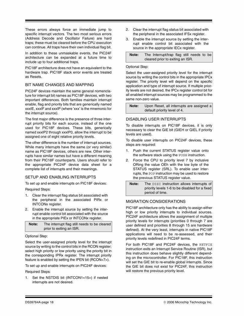
These errors always force an immediate jump tospecific interrupt vectors. The two most serious errors(Address Decode and Oscillator Failure) are hardtraps; these must be cleared before the CPU executioncan continue. All traps have their own individual flag bit.
In addition to these unmaskable events, the PIC24Farchitecture can be expanded at a future time toinclude up to four additional traps.
PIC18F architecture does not have an equivalent to thehardware trap. PIC18F stack error events are treatedas Resets.
BIT NAME CHANGES AND MAPPING
PIC24F devices maintain the same general nomencla-ture for interrupt bit names as PIC18F devices, with twoimportant differences. Both families maintain interruptenable, flag and priority bits that are generically namedxxxIE, xxxIF and xxxIP (where ’xxx’ is the mnemonic forthe interrupt source).
The first major difference is the presence of three inter-rupt priority bits for each source, instead of the oneused for PIC18F devices. These bits, genericallynamed xxxIP2 through xxxIP0, allow the interrupt to beassigned one of eight relative priority levels.
The other difference is the number of interrupt sources.While many interrupts have the same (or very similar)name as PIC18F devices, others are new. Other inter-rupts have similar names but have a different meaningfrom their PIC18F counterparts. Users should refer tothe appropriate PIC24F device data sheet for acomplete list of interrupts and their meanings.
SETUP AND ENABLING INTERRUPTS
To set up and enable interrupts on PIC18F devices:
Required Steps:
1. Clear the interrupt flag status bit associated withthe peripheral in the associated PIRx orINTCONx register.
2. Enable the interrupt source by setting the inter-rupt enable control bit associated with the sourcein the appropriate PIEx or INTCONx register.
Optional Step:
Select the user-assigned priority level for the interruptsource by writing to the control bits in the RCON register;select high priority or low priority using the priority bit inthe corresponding IPRx register. The interrupt priorityfeature is enabled by setting the IPEN bit (RCON<7>).
To set up and enable interrupts on PIC24F devices:
Required Steps:
1. Set the NSTDIS bit (INTCON1<15>) if nestedinterrupts are not desired.
2. Clear the interrupt flag status bit associated withthe peripheral in the associated IFSx register.
3. Enable the interrupt source by setting the inter-rupt enable control bit associated with thesource in the appropriate IECx register.
Optional Step:
Select the user-assigned priority level for the interruptsource by writing the control bits in the appropriate IPCxregister. The priority level will depend on the specificapplication and type of interrupt source. If multiple prior-ity levels are not desired, the IPCx register control bit forall enabled interrupt sources may be programmed to thesame non-zero value.
DISABLING USER INTERRUPTS
To disable interrupts on PIC18F devices, it is onlynecessary to clear the GIE bit (GIEH or GIEL if prioritylevels are used).
To disable user interrupts on PIC24F devices, thesesteps are required:
1. Push the current STATUS register value ontothe software stack using the PUSH instruction.
2. Force the CPU to priority level 7 by inclusiveORing the value OEh with the low byte of theSTATUS register (SRL). To enable user inter-rupts, the POP instruction may be used to restorethe previous STATUS register value.
MIGRATION CONSIDERATIONS
PIC18F architecture only has the ability to assign eitherhigh or low priority interrupts to individual sources.PIC24F architecture allows the assignment of multiplepriority levels for interrupts (priorities 0 through 7 areuser defined and priorities 8 through 15 are hardwaredefined). At the very least, interrupts in native PIC18Fapplications will need to be re-assessed, and theirpriority levels redefined in PIC24F terms.
For both PIC18F and PIC24F devices, the RETFIEinstruction exits an Interrupt Service Routine (ISR), butthis instruction does behave slightly different depend-ing on the microcontroller. For PIC18F, this instructionwill set the GIE bit to re-enable global interrupts. Sincethe GIE bit does not exist for PIC24F, this instructionwill restore the previous priority level.
Note: The interrupt flag still needs to be clearedprior to exiting an ISR.
Note: The Interrupt/trap flag still needs to becleared prior to exiting an ISR.
Note: Upon Reset, all interrupts are assigned adefault priority level of 4.
Note: The DISI instruction allows interrupts ofpriority levels 1-6 to be disabled for a fixedperiod of time.

© 2006 Microchip Technology Inc. DS39764A-page 19
Oscillator
The PIC24F oscillator system supports many of thefeatures of PIC18F nanoWatt Technology, and addsseveral new features. Both architectures support threemajor clock sources: primary oscillators, internal RCoscillators and 4x PLL frequency multipliers. In addi-tion, both also support features to enhance applicationrobustness, such as software-controlled clock switch-ing, Fail-Safe Clock Monitors and Two-Speed Start-up.PIC24F devices increase the flexibility of initial clockconfiguration, software controlled clock switching andthe use of the PLL.
Although there are many similarities between PIC24Fand PIC18F architectures in the oscillator and clockgeneration, there are also important differences in theimplementation of these features. Because the oscilla-tor affects most aspects of an application, it is importantto understand the differences before migrating anapplication to a PIC24F device.
The major differences between the PIC18F andPIC24F clock structures are detailed in Table 14.
CHANGES FROM PIC18F ARCHITECTURE
Features added from the PIC18F implementation ofnanoWatt Technology include:
• Enhanced PLL Operation: PIC24F architecture allows the PLL to be used under software control in all modes where it is available, and makes the PLL available to all External Primary Oscillator modes.
• Doze Mode: This permits differential clocking of the CPU and peripherals, and allows the CPU to run at lower speeds while maintaining timing sensitive peripherals (see the “Power-Saving Features” section on page 23 for more details).
PIC18F features that are no longer supported inPIC24F architecture include:
• LP and External RC Primary Oscillator modes have been removed in favor of SOSC and FRC Oscillator modes
• XT mode is still implemented, but is limited to the upper end of the upper range of frequencies available with PIC18F devices. For PIC24F devices, the XT frequency range is 3.5 MHz to 10 MHz.
TABLE 14: COMPARISON OF MAJOR OSCILLATOR FEATURES
Feature Description PIC18F PIC24F
Primary (External) Oscillator Modes HS, XT, EC, LP and external RC(1)
HS, XT and EC(all devices)
Secondary (Timer1) Oscillator Yes Yes (SOSC)
8 MHz Internal RC Oscillator Most devices (INTOSC)(1) Yes (FRC)
31 kHz Internal RC Oscillator Yes (INTRC) Yes (LPRC)
4x PLL Options:XTPLL (MSPLL)ECPLLINTOSCPLL/FRCPLL
NoSelect devices onlySelect devices only
YesYesYes
INTOSC/FRC Tuning 5-bit magnitude, ±12% range 6-bit magnitude, ±12% range
Software Clock Switching Between clock sources only Between all available oscillator types; uses safety interlock
Doze Mode No Yes
Fail-Safe Clock Monitor Yes Yes
Two-Speed Start-up Yes Yes
Note 1: Applies to most PIC18FXXXX devices, such as PIC18F8722. Currently, PIC18FXXJ Flash devices, such as the PIC18F87J10, only offer HS and EC Primary Oscillator modes and no INTOSC oscillator.

DS39764A-page 20 © 2006 Microchip Technology Inc.
BIT AND CONTROL FUNCTION MAPPING
There is not a precise one-to-one correspondencebetween configuration and control functions of thePIC18F and PIC24F architectures. The most commondifferences are shown in Table 15. Details arediscussed later in this section.
TABLE 15: COMPARISON OF OSCILLATOR BIT AND CONTROL FUNCTION MAPPING
PRIMARY OSCILLATORS (POSC)
PIC18F microcontrollers, with the latest versions ofnanoWatt Technology, use an oscillator circuit that sup-ports a wide range of external components, including avariety of crystals, RC networks or external clock gener-ators. To use the oscillator, users connect their crystal orRC circuit to the OSC1 and OSC2 pins, or present theexternal clock on OSC1. The exact oscillator mode to beused is selected during device configuration using theFOSC3:FOSC0 Configuration bits, and must match theactual external circuit to be used.
PIC24F microcontrollers support a similar range ofoscillator options on the OSC1 and OSC2 pins;however, the options for support of low-power,low-frequency crystals and external RC resonantcircuits have been omitted. These have been replacedby the use of a high-speed internal RC oscillator, andthe use of the Timer1 oscillator in the more flexibleclock structure.
The primary oscillator mode is selected during configu-ration with a combination of the FNOSC2:FNOSC0 andPOSCMD<1:0> Configuration bits. Like PIC18Fdevices, the configuration must match the externalcircuit to be used in the application.
SECONDARY OSCILLATOR (SOSC)
All PIC18F devices have the option to use the Timer1oscillator as a secondary clock source. The mosttypical arrangement for this option is to connect alow-power, 32 kHz watch crystal across pins T1OSIand T1OSO. The oscillator is controlled separatelyfrom the device clock controls with the T1OSCEN bit(T1CON<3>).
PIC24F devices also provide a secondary oscillatorthat is identical in function to the Timer1 oscillator; itonly differs in that it is controlled through the OSCCONregister with the SOSCEN bit. The crystal input/outputpins are renamed SOSCI and SOSCO.
The PIC24F secondary oscillator takes the place of thePrimary LP Oscillator mode provided on PIC18Fdevices, but not supported on PIC24F. To use SOSC asthe default oscillator on start-up, it must by selected indevice configuration by the FNOSC2:FNOSC0 bits andenabled in software by setting the SOSCEN bit.
Oscillator Block Function PIC18F PIC24F
Define Start-up Oscillator
FOSC3:FOSC0(CONFIG1H<3:0>)(1)
FNOSC2:FNOSC0(Configuration Word 2<10:8>)
Define Primary Oscillator Type POSCMD1:POSCMD0(Configuration Word 2<1:0>)
Define I/O Port Functions in EC Oscillator Modes
OSCIOFCN(Configuration Word 2<5>)
Enable Secondary Oscillator T1OSCEN (T1CON<3>) SOSCEN (OSCCON<1>)
Select INTOSC/FRC Postscaler IRCF2:IRCF0 (OSCCON<6:4>) RCDIV2:RCDIV0 (CLKDIV<10:8>)
Switch Run-Time Clock SourceSCS1:SCS0 (OSCCON<1:0>)
NOSC2:NOSC0, OSWEN(OSCCON<10:8, 0>), FCKSM0
(Configuration Word 2<6>)
Active Clock Source Monitoring OSTS, IOFS, T1RUN COSC2:COSC0
Enable Two-Speed Start-up IESO (CONFIG1H<7>) IESO (Configuration Word 2<15>)
Enable Fail-Safe Clock MonitorFCMEN (CONFIG1H<6>)
FCKSM1:FCKSM0 (Configuration Word 2<7:6>)
Note 1: PIC18FXXXX devices only; FOSC2:FOSC0 (CONFIG2H<2:0>) on current PIC18FXXJ Flash devices.

© 2006 Microchip Technology Inc. DS39764A-page 21
INTERNAL RC OSCILLATORS (INTOSC/FRC AND INTRC/LPRC)
The internal oscillators for PIC18F devices withnanoWatt Technology and PIC24F devices are virtuallyidentical, except in name. Both feature two independentinternal oscillators, an efficient 31 kHz oscillator and anaccurate, high-speed 8 MHz oscillator. Both architec-tures use a configurable postscaler, driven by the 8 MHzsource, to provide a range of clock frequencies, from31 kHz to 4 MHz (as well as the undivided 8 MHzoutput). Both architectures allow software selection fromthe 31 kHz or 8 MHz oscillators to provide the 31 kHzsource for various system features. Both clock systemspermit tuning of the 8 MHz source through a nominalrange of ±12%.
The differences here are minor. For PIC18F devices,the internal 31 kHz and 8 MHz sources are generallyreferred to as INTOSC and INTRC. For PIC24Fdevices, they are known as the Fast RC (FRC) andLow-Power RC (LPRC) oscillators. INTOSC/FRC tun-ing is accomplished with 5 tuning bits (TUN4:TUN0) inPIC18F devices; PIC24F devices use 6 tuning bits(TUN5:TUN0) for finer resolution. Finally, the defaultvalue on Reset for the 8 MHz postscaler is 1 MHz forPIC18F devices and 4 MHz for PIC24F devices.
PLL FREQUENCY MULTIPLIER
PIC18F and PIC24F devices both support a 4x PLLfrequency multiplier for use with select clock sources.In all cases, the PLL provides a stable output only whenthe input frequency is between 4 and 10 MHz. Theoperation of the PLL differs substantially between thetwo architectures.
For most PIC18F devices incorporating nanoWattTechnology, the PLL is automatically enabled forspecific, primary oscillator configurations and is alwaysoperational. All devices can use the HS oscillator withthe PLL; select later devices also allow the use of thePLL with the EC mode. These are distinct primaryoscillator configurations. If the user wishes to disable thePLL, the device must be reprogrammed and reconfig-ured. If the internal oscillator block is selected as thedevice’s default oscillator, the PLL is made availablewhen the INTOSC postscaler is configured for an outputof 4 or 8 MHz. In these cases, the PLL can be selectivelyenabled under software control with the PLLEN controlbit (OSCTUN<6>).
For PIC24F devices, the PLL is always available undersoftware control. It is available for all primary oscillatormodes, as well as FRC or FRCDIV operation (as longas a postscaler output of at least 4 MHz is selected). Touse the PLL, it is only necessary to perform a clockswitch to one of the PLL Clock modes. Once a PLLmode is selected, the state of the PLL’s output stabilityis indicated by the flag bit, LOCK (OSCCON<5>).When the bit is set, the PLL output is stable.
CLOCK SWITCHING
Clock switching differs significantly between PIC18Fand PIC24F devices. Conceptually, both architectureshave three categories of oscillators: primary (externalcomponents connected to OSC pins), secondary(external crystal connected to T1OSC or SOSC pins)and internal RC. PIC18F devices permit the definitionof one and only one primary oscillator type used duringdevice configuration. This is the oscillator that is alwaysused when on device power-up and Reset. Thereafter,the device can switch between primary, secondary andinternal oscillator sources, under software control, bywriting to the SCS1:SCS0 bits. Once a primaryoscillator is defined, it cannot be changed unless thedevice is reprogrammed.
For PIC24F devices, any one of the three major clocksources can be configured as the default start-up oscil-lator; users are no longer confined to just the primaryoscillator sources. During run time, the device canswitch between any of the available oscillator modesunder software control. This means, that among otherthings, it is possible to switch between a Primary Clockmode and its PLL counterpart while the application isrunning. It is also possible to start the device using theTimer1 or LPRC oscillator, rather than switch to thosesources after Reset or power-up (as was required inPIC18F implementations of nanoWatt Technology). Infact, it is possible to completely disable the primaryoscillator source in PIC24F devices; something thatcannot be done on the PIC18F architecture.
This increased flexibility makes clock switching onPIC24F devices a more complex sequence. The newoscillator is selected with the NOSC2:NOSC0 bits andby setting the Oscillator Switch Enable bit, OSWEN. Toprevent unintended changes, PIC24F devices also usean additional safety interlock that requires an unlocksequence to write each byte of the OSCCON register.PIC24F unlocks the high or low byte for one instructionafter two specific literals are written to the high or lowbyte of OSCCON. An instruction counter ensures theunlock sequence is performed within a maximumnumber of instructions and remains unlocked for oneinstruction cycle. Because these sequences are sotime critical, the unlock sequences are done with anassembly language routine. When the NOSC bitsmatch the COSC bits, or the OSWEN bit is clear, theclock switch has been completed successfully.Because the New Oscillator Select bits, NOSC, andOscillator Switch Enable bit, OSWEN (OSCCON<0>),reside in opposite halves of OSCCON, two unlocksequences are needed to request a system clockswitch. For examples of the OSCCON unlocksequences, refer to the specific device data sheet.

DS39764A-page 22 © 2006 Microchip Technology Inc.
TWO-SPEED START-UP
Two-Speed Start-up is implemented identically inPIC18F and PIC24F devices. In both cases, the featureis controlled by the IESO Configuration bit.
FAIL-SAFE CLOCK MONITOR
The Fail-Safe Clock Monitor feature is also available forthe PIC24F. It is controlled, along with run-time clockswitching, by the Configuration Word bits,FCKSM1:FCKSM0 (CW2<7:6>). FSCM in PIC24Fdevices is similar to the PIC18F implementation byautomatically switching to the FRC when the primaryoscillator stops.
The single significant difference is the secondaryeffects of an FSCM event. For PIC18F devices, aprimary oscillator failure sets the OSCFIF interrupt flagbit, which can optionally generate a device interrupt.For PIC24F devices, an FSCM event sets both the CFflag (OSCCON<3>) and OSCFAIL (INTCON1<1>) bits,and generates an unmaskable hardware trap whichthen must be cleared.
MIGRATING A TYPICAL APPLICATION
• Most applications built on a PIC18F device with nanoWatt Technology will be able to use the same oscillator type and clock frequency when a PIC24F device is substituted. This is particularly true when the oscillator uses a crystal (HS mode or XT mode, between 3.5 and 10 MHz), an external clock generator or the internal RC oscillator block.
• PIC18F applications that use a 32 kHz crystal for the primary oscillator will need to use the secondary oscillator for their PIC24F equivalent versions. The crystal circuit will need to be moved to the T1OSCI/T1OSCO pins, and the Secondary Oscillator mode (SOSC) will need to be selected as the start-up clock source.
• PIC18F applications using an External RC Primary Oscillator mode, or an XT Oscillator mode running below 3.5 MHz, must now use the FRC oscillator as the default clock source. Configuration will need to be changed to select FRC as the default start-up clock source.
• If clock switching is used, the clock switch sequences will need to be added. These are described in the appropriate device data sheet.
MIGRATION CONSIDERATIONS
When migrating to a PIC24F microcontroller (or anymicrocontroller, for that matter), any application that isbased on a crystal clock source should be re-evaluatedfor oscillator operation and stability. It is important toverify that the crystal performance is reliable across thevoltage, temperature and process variationsanticipated for the application.
For more information, refer to the application noteslisted in the “References” section on page 45.

© 2006 Microchip Technology Inc. DS39764A-page 23
Power-Saving Features
PIC24F power-saving features are very similar to thePower-Saving modes offered in PIC18F nanoWattTechnology devices. Both architectures includerun-time switching of system clock sources, Idle andSleep modes, and hardware invoked exits throughResets and interrupts. PIC24F devices describe thesefeatures in a somewhat different manner, and supportadditional features for strategic reduction of powerconsumption.
A comparison of the power-saving features in botharchitectures is presented in Table 16.
TABLE 16: COMPARISON BETWEEN PIC18F AND PIC24F POWER-SAVING FEATURES
RUN-TIME CLOCK SWITCHING
PIC18F and PIC24F devices have all the same types ofsystem clock sources (primary, secondary and internaloscillator). In addition, Sleep and Idle modes aredefined in the same manner. The difference betweenthe devices is strictly terminology: PIC24F devices donot use the Power-Managed mode terminology createdfor nanoWatt Technology. Because oscillator modeswitching in more expansive in PIC24F devices, the oldPIC18F descriptions of Power-Managed modes(PRI_RUN, SEC_IDLE, etc.) are no longer used. How-ever, completely equivalent modes are available inPIC24F devices; that is, using the NOSC2:NOSC0 bitsto select the FRC oscillator as the clock source isequivalent to switching to RC_RUN mode in a PIC18Fdevice.
In PIC18F devices, clock switching is accomplished bywriting to the SCS1:SCS0 bits (OSCCON<1:0>). ForPIC24F devices, clock switching is accomplished bywriting to the NOSC2:NOSC0 bits, accompanied by asafety unlock procedure (see the “Oscillator” sectionon page 19 for more details). In addition, clock switch-ing can be disabled entirely by setting Configuration bit,FCKSM1 (CW2<7>).
The internal transitions between clock sources areessentially the same in both architectures and areaccompanied by similar delays.
SLEEP AND IDLE MODES
PIC18F devices use the SLEEP instruction to invoketheir Power-Managed (x_IDLE and Sleep) modes. Theactual mode invoked is determined by the IDLEN bit(OSCCON<7>); an Idle mode is entered when the bit isset or Sleep mode when the bit is cleared.
In PIC24F devices, the equivalent instruction isPWRSAV. The instruction is used with an argument(either symbolic or literal) to specify the desired mode.As before, Idle mode is invoked when the literalargument is ‘1’, and Sleep mode when it is ‘0’.
SELECTIVE PERIPHERAL IDLING
In PIC18F devices, Idle mode is an all-or-nothing affair;all peripherals remain operational during an Idle mode.
In PIC24F devices, peripherals can be selectivelydisabled during Idle mode. Most peripheral moduleshave a control bit, xxxIDL (where ‘xxx’ represents theperipheral mnemonic), that determines if the peripheralcontinues operation when Idle mode is invoked. TheIDL bits allow modules to be partially powered down,providing for additional incremental power savings.
EXITING POWER-SAVING MODES
Exiting a Power-Managed mode can be achieved by anenabled interrupt or by a Reset. A WDT Reset or inter-rupt exits the Power-Managed mode and returns thedevice to the previous clock source. All other methodsswitch the controller to the 8 MHz FRC internal oscillator,if Two-Speed Start-up is enabled, until the primary clocksource is ready.
Note: For the sake of brevity, references to“PIC18F” throughout this section shouldbe interpreted as meaning “PIC18Fdevices with nanoWatt Technology”.
Feature Description PIC18F PIC24F
Run-Time Clock Switching Yes Yes
Power-Saving Mode Invocation Instruction and hardware bit setting Instruction with argument
Idle ModeSelective Peripheral Idle
YesNo
YesYes
Sleep Mode Yes Yes
Doze Mode No Yes
PMD Option No Yes

DS39764A-page 24 © 2006 Microchip Technology Inc.
DOZE MODES
PIC24F devices feature an additional Doze mode optionto reduce power consumption while allowing the applica-tion to continue running. Doze mode permits the CPU torun at a reduced clock rate while the peripherals areclocked at full speed. It is enabled by setting the DOZENbit (CLKDIV<11>). The CPU peripheral clock ratio isselected using the DOZE bits (CLKDIV<14:12>), with arange of 1:128 (slowest) to 1:1 (full speed). An option todisable Doze mode on an interrupt is available throughthe Recover on Interrupt bit, ROI (CLKDIV<15>).
PIC18F devices have no equivalent feature.
PERIPHERAL MODULE DISABLE
In PIC24F devices, the PMD feature reduces peripheralcurrent consumption to the absolute minimum possible.Peripherals which support PMD have an associatedcontrol bit in one of the PMD registers. When enabled,all clock sources are disconnected from the peripheral,and all SFR registers associated with it appear as unim-plemented memory. This is a contrast to the SelectivePeripheral Idle, where the module is partially powereddown but remains accessible.
There is no equivalent feature in PIC18F architecture.
ADDITIONAL PIC24F FEATURES
The internal voltage regulator can be brought into alow-power mode by setting the VREGS bit(RCON<8>). In this mode, the voltage regulatorsupplies only enough power to maintain RAM states. Ifany peripherals are active, this mode cannot be used.
MIGRATING A TYPICAL SETUP
For straight migrations of a PIC18F application usingPower-Saving modes, there is a tight correspondencebetween PIC18F and PIC24F instructions. Users willneed to change references from SCS1:SCS0 to theequivalent mode using NOSC2:NOSC0 (plus the addi-tion of the register unlocking sequence). Additionally,all SLEEP instructions will need to be changed to theappropriate PWRSV n equivalent, and references toIDLEN removed.
MIGRATION CONSIDERATIONS
• The voltage/frequency characteristics of the PIC18F and PIC24F architectures are signifi-cantly different and will affect clock switching deci-sions. The PIC24F voltage supply range (2.0V to 3.6V) is narrower than for PIC18F devices, such as the PIC18F8722. Applications that change clock frequencies, due to reduced power supply voltage, may not need to switch at all, since the PIC24F can operate at higher speeds across a wider range of voltage. Also note that PIC18FXXJ Flash devices, such as the PIC18F87J10, have V/F characteristics that are similar to the PIC24F family.
• The lower maximum VDD of PIC24F devices may also impact the design of an application migrated from PIC18F devices. Refer to the appropriate product data sheets for more information on operating voltage range and Power-Managed modes.

© 2006 Microchip Technology Inc. DS39764A-page 25
Watchdog Timer (WDT)
The Watchdog Timer (WDT) module for the PIC24F isnearly identical to the PIC18F nanoWatt deviceimplementation. Both use Configuration bits to enablethe WDT and to select a time-out period. The time-outperiods are the same and both feature a software
enable option. Power-Managed modes can also beexited using the WDT for both devices. In addition, thePIC24F implementation has a new configurableprescaler and windowed WDT options available in theConfiguration Word.
TABLE 17: COMPARISON BETWEEN PIC18F AND PIC24F WDT FEATURES
COMMON FEATURES
The WDT modules for both PIC18F and PIC24Fdevices can be enabled during programming in theConfiguration Word. The PIC24F is enabled or dis-abled by the FWDTEN (CW1<7>) Configuration bit. Atime-out period is also selected in the ConfigurationWord with the WDTPS<3:0> bits (CW1<4:0>), rangingfrom 1 ms to 131s. The periods are the same for bothdevices within the accuracy limitations of the 32 kHzLow-Power Internal Oscillator (LPRC). Both implemen-tations automatically enable the 32 kHz LPRC if it is notalready enabled.
Sleep and Idle modes can be exited using the WDT. If atime-out occurs in one of these modes, code executionresumes at the next instruction in program memory.Also, the WDT can be enabled in software by setting theSWDTEN (RCON<5>) bit if the option is disabled in theConfiguration Word. Both architectures clear the WDTcounter in the following events:
• CLRWDT instruction
• SLEEP instruction• Selecting a new internal oscillator frequency
NEW PIC24F FEATURES
The PIC24F WDT has a prescaler option in the Config-uration Word to select either 1:128 or 1:32 using theFWPSA bit (CW1<4>). To match the PIC18F nanoWattimplementation, set the FWPSA to select the 1:128option.
The windowed WDT feature is enabled by clearing theConfiguration bit, WINDIS. For more information on thewindowed WDT option, refer to the applicable productdata sheet.
UNSUPPORTED PIC18F FEATURES
All PIC18F WDT features are supported in the PIC24FWDT.
MIGRATING A TYPICAL SETUP
Migrating PIC18F WDT to PIC24F is straightforward.Enable the WDT in the same manner, either by settingthe FWDTEN Configuration bit, or in software, bysetting the SWDTEN bit in the RCON register. Selectthe same postscaler setting used in the PIC18F config-uration with the WDTPS<3:0> bits and set the FWPSAConfiguration bit to choose the 1:128 prescaler setting.The PIC24F WDT can be used in the same manner asthe PIC18F to exit Power-Managed modes and monitorfor unexpected code execution.
MIGRATION CONSIDERATIONS
• The PIC24F WDT counter will be cleared on any clock source switch, whether it was caused from the Fail-Safe Clock Monitor, or by software. This may differ from the PIC18F implementation that typically clears the WDT on the conditions specified in the section, “Common Features”, on page 25.
• When a WDT time-out occurs, PIC18F devices clear the TO (RCON<3>) bit and PIC24F devices set the WDTO (RCON<4>) bit. On POR or BOR, the state of these bits is unknown and must be initialized to the opposite state to detect a WDT time-out event.
Feature Description PIC18F PIC24F
Configurable Time-out Period Yes Yes
Software Enable Yes Yes
Exit Power-Managed Modes Yes Yes
Time-out Range 1 ms to 131s 1 ms to 131s
Prescaler No Yes
Windowed WDT Option No Yes

DS39764A-page 26 © 2006 Microchip Technology Inc.
Device Integration Features
Certain features of PIC18F and PIC24F devices are notconsidered as individual modules, but part of a systemintegration package that makes the devices morereliable and their applications more cost-effective. Inaddition to the WDT, included in this group are:
• Device Configuration Control• Code Protection
• On-Chip Voltage Regulator
DEVICE CONFIGURATION
All PICmicro microcontrollers program their basic andgenerally, application constant configuration settinginto an area of nonvolatile memory inside the deviceconfiguration space. The manner in which this informa-tion is stored and used differs greatly between PIC18Fand PIC24F families.
All PIC18F devices use Configuration registers ataddresses 300000h through 30000Fh, well outside ofthe normal program space. While all devices can readthese addresses during run time, most cannot changetheir configuration settings through self-reprogramming.Changes to the Configuration Words can only be donewith external programming, such as ICSP. In some earlydevices, the configuration settings were implementedwith one-way fuses, and were essentially permanent.
Later versions of PIC18F devices, such as PIC18FXXJFlash devices, store their configuration settings in thelast four words at the top of program memory. At POR,the information is latched into the actual registers (stillat addresses 300000h through 30000Fh), which con-trols the device configuration. The actual registers inconfiguration space cannot be directly written to by theuser, or programmed via ICSP. While the configurationdata in program memory can be altered during run timeusing table write operations, the new configuration isnot latched into the actual Configuration registers anddoes not take effect until a POR occurs. Even then,changes to device code protection cannot be donewithout a Chip Erase and complete reprogramming.The actual Configuration registers are parity-protectedagainst spurious bit changes; any unexpected changeswill result in a device Reset.
Like PIC18FXXJ Flash devices, PIC24F devices storetheir Configuration Words at the end of implementedprogram memory. Unlike PIC18F, these devices rereadand latch the configuration settings on all types of deviceResets, including the use of the RESET instruction. Thismeans that any aspect of device configuration, exceptfor code protection, can essentially be updated in soft-ware at any time. Code protection settings are stillspecially protected, and can only be changed by a ChipErase and complete reprogramming. Like PIC18FXXJFlash devices, the actual Configuration registers areparity-protected against spurious changes.
CODE PROTECTION
All PIC18F and PIC24F devices incorporate somevariety of code protection system that preventsprogrammed areas from being altered, or read back atany time, except during code execution.
Implementation of this feature on PIC18F devicesvaries from family to family in terms of how the programmemory area is divided into individual blocks and thesize of these blocks. Some PIC18F device familiesprovide for separate boot block protection, for a smallsegment at the bottom of the program memory, in orderto create a secure area for a bootloader program. Alldevices with data EEPROMs also provide code protec-tion for this area as a separate block. Protection for allblocks is configured independently with three bits:
• CPn, to prevent reads and writes from outside of the device
• WRTn, to prevent all table writes
• EBTRn, to prevent table read operations executed from another code block
In contrast, PIC24F code protection is all-or-nothing:the entire program memory is either protected as oneblock or it is not. Protection is configured by two bits:GCP, which functions as the PIC18F CPn bit, andGWRP, which functions as the PIC18F WRTn.
ON-CHIP VOLTAGE REGULATOR
PIC24F devices use low-power circuitry for their digitallogic. To ensure proper power distribution between thecore and peripheral I/O systems, these devices alsoinclude an on-chip voltage regulator. The regulatorallows the device to be powered from a single voltagesource at the upper end of the VDD range, and providesthe option to power the logic core separately if needed.The regulator is hardware configured by tying an exter-nal regulator pin to VDD or ground. For completedetails, refer to the appropriate device data sheet.
The on-chip regulator is a departure from previousPIC18F devices which used common VDD and VSS
busses for all on-chip circuits. The exception is thePIC18FXXJ Flash family which uses the same regula-tor system. Applications originally designed for thesedevices will be pin compatible with an equivalentPIC24F device, at least from the standpoint of power.

© 2006 Microchip Technology Inc. DS39764A-page 27
PIC24F PERIPHERAL SET
I/O Ports
PIC24F ports are very similar to PIC18F but have note-worthy differences. Both devices have data PORT, LATand TRIS registers. Both analog and digital peripherals
are multiplexed onto ports. Ports on the PIC24F featuremore pins on more ports that have configurableopen-drain and interrupt-on-change (CNx) inputoptions.
TABLE 18: COMPARISON BETWEEN PIC18F AND PIC24F PORT FEATURES
For both architectures, pins configured as analoginputs are read as ‘0’ when the associated PORTx bitis read by the CPU and the output driver is disabled.This prevents shoot-through current in the port outputdriver.
Reading the PORTx register will return the digitalrepresentation of the pin voltage. This value will reflectan override from either a peripheral or external pinvoltage.
Peripherals with digital outputs require the TRISx bit tobe cleared in software. While the peripheral is enabled,the pin output can be read with the PORTx register.Enabling the peripheral may affect the output’s slewrate and/or drive strength. Peripherals with the ability totri-state the output will override the TRISx register,although the change will not affect the TRISx registervalue. Refer to the product data sheet for moreinformation on peripheral outputs.
Bidirectional peripherals can override the port outputbut not the input. Setting the TRISx bit to ‘1’ allows theperipheral to control the data direction. Reading thePORTx register will provide the port levels. The outputmay be affected by the peripheral’s slew rate or drivestrength overrides.
Reading the PORTx register will read the digital repre-sentation of the voltages on the pins. Reading the LATxregister, reads the latched output value. Writing thePORTx register or the LATx register will write the LATxregister.
On all Resets, the TRISx bits are set, causing the portsto configure as inputs and, where possible, analoginputs. This minimizes the pin load onto the applicationand the potential for shoot-through current in the digitalport inputs.
Feature Description PIC18F PIC24F
Voltage Inputs Above VDD + 0.3V Permitted No Digital-only pins
Pull-up Option PORTB (all pins) Multiple pins, individually selectable
Interrupt-on-Change PORTB (3 pins) Multiple pins, individually selectable
Control Registers PORTx, LATx and TRISx PORTx, LATx, TRISx and ODCx
Configured to Inputs on Reset Yes Yes

DS39764A-page 28 © 2006 Microchip Technology Inc.
NEW PIC24F FEATURES
• Open-drain inputs, when enabled, are active for both port and peripheral activities. The I2C™ pins already have this function and are unaffected by the ODCx register setting.
• The Parallel Master Port (PMP) inputs are unique for the input buffer and can be software selected as either a TTL or Schmitt Trigger (ST) input buffer. This feature is available through the PADCFGx register.
• Digital-only pins are 5.5V input tolerant and are convenient for interfacing into 5V components.
• Additional pins are available for interrupt-on-change and open-drain configurations.
• The PMP is now a separate peripheral and not integrated into the I/O port functions as was the PIC18F Parallel Slave Port (PSP). Please see the product data sheet for additional information.
• Pull-ups are only available on PORTB in PIC18F devices and have a single enable bit to control all pull-ups. PIC24F supports pull-ups that can be selectively enabled on individual pins.
• Interrupt-on-change on PIC18F devices is also implemented with a single control bit for three PORTB pins. PIC24F interrupt-on-change pins can all be individually enabled.
UNSUPPORTED PIC18F FEATURES
The PIC24F port architecture does not permit the portoutput to drive the peripheral input. The user musteither configure the pin as a peripheral input, or portoutput, but not both.
MIGRATION CONSIDERATIONS
• Enabling a digital or analog input or output onto a pin with a configurable open-drain option will not cause the pull-up to be automatically disabled. The pull-up is not disabled if the pin has a config-urable open-drain option. It is important to disable the pull-up in software when it is not needed.
• Pins without an analog function can tolerate input voltages up to 5.5V. This can minimize hardware changes when migrating from a PIC18F device. A higher voltage output can be created by adding an external pull-up resistor on the pin and writing a zero to the data latch. Setting the TRIS bit will pull the output up to the supply voltage and clearing the TRIS bit will output a digital zero.
• Drive strength, slew rate and input voltage thresh-olds can change automatically when a peripheral is enabled. It is important to review the specific data sheets for differences between devices.
• Most of the input buffers for PIC24F devices are Schmitt Trigger (ST). Verify that the output levels of associated components meet the ST input voltage thresholds.

© 2006 Microchip Technology Inc. DS39764A-page 29
Timers (Timer1, Timer2/3 and Timer4/5)
PIC24F timers support all of the PIC18F nanoWattfeatures, which include Asynchronous and Synchro-nous Counter modes, Timer modes and 32 kHz crystalsupport. PIC24F timers are designed to have moregeneric functions, whereas PIC18F timers are intendedfor dedicated purposes, such as PWM clock sources or
a generic timer function. Each PIC24F 16-bit timer hasa dedicated period register, selectable prescaler andperiod match flag, and can operate in either Counter orTimer mode. PIC24F timers add new features, such asthe ability to combine two timers into a single 32-bittimer and a timer gate option.
TABLE 19: COMPARISON BETWEEN PIC18F AND PIC24F TIMER FEATURES
Although all timer functionality of the PIC18F nanoWattdevices is available in the PIC24F family, different func-tions may reside in different timers. Like the PIC18F, allPIC24F timers can operate using the system clock asthe clock source. Where Asynchronous Counter modewas available in only Timer1 and 3 for PIC18F, thisfunction is available in Timer1, 2 and 4 for PIC24F.Synchronous Counter mode is provided in all PIC24Ftimers, as well as providing a dedicated period register.The period register resets the timer on a clock cyclematch and sets the interrupt flag in both architectures.However, when using the PIC24F period register,ensure the timer gate option is disabled.
Prescalers are available in both architectures. PIC18Ftimers have different prescale ranges, but PIC24Ftimers use a standard range for all timers (1:1, 1:8, 1:64and 1:256).
Both architectures support 32 kHz crystals throughTimer1, which can be optionally used as an accurate,low-power system clock source. Refer to the “Oscillator”and “Power-Saving Features” sections on pages 19and 23, respectively, for more information on usingTimer1 as a system clock.
Other device similarities include:
• Timers can operate if the device is in Sleep mode when the timer is configured for Asynchronous Counter mode or Timer1 32 kHz Crystal mode.
• All timer modes are available in Idle mode since the peripheral has a clock source.
• Both Sleep and Idle mode can be exited on a timer interrupt event.
• A Special Event Trigger is available to start an A/D conversion. Refer to the product data sheet for which timer(s) is capable of generating a Special Event Trigger.
TABLE 20: PIC18F AND PIC24F BIT EQUIVALENT TIMER FUNCTIONS
Feature Description PIC18F PIC24F
Timer Width 8/16-bit 16/32-bit
General Purpose Timer Mode All timers All timers
Asynchronous Counter Mode Timer1 and 3 Timer1, 2 and 4
Synchronous Counter Mode Timer0, 1 and 3 All timers
Period Register Timer2 and 4 All timers
32 kHz Crystal Support Timer1 Timer1
Timer Gate Option No All timers
Prescaler All timers All timers
Postscaler Timer2 and Timer4 No
Special Event Trigger Yes Yes
System Clock Source Rate FOSC/4 FOSC/2
Functionality PIC18F PIC24F
Timer Enable TMRxON TON
Double Read/Write Buffer Mode RD16 T32Timer1 System Clock Status T1RUN COSC2:COSC0 = 100
(OSCCON<14:12>)Timer Prescale Select TxCKPSx TCKPSx
Timer1 Oscillator Enable T1OSCEN SOSCEN (OSCCON<1>)
Timer External Clock Synchronization TxSYNC TSYNC
Timer Clock Source Select TMRxCS TCSTimer Postscale Select TxOUTPSx N/A

DS39764A-page 30 © 2006 Microchip Technology Inc.
NEW PIC24F FEATURES
The most apparent difference between PIC18F andPIC24F timers is the size. All PIC24F timers are 16-bitand can be paired together to form a 32-bit timer. In32-bit mode, a holding register latches the upper16 bits when the lower 16 bits are read. The upper16 bits are written first, which are latched until the lowerhalf is written. This feature allows all 32 bits to bewritten or read without concern of a register rollover.
A timer gate option is available for PIC24F timers. Thisoption enables the timer, when the TxCK pin is high, toset the interrupt flag on a high-to-low transition on theTxCK pin. A period match will not set the interrupt flag.
UNSUPPORTED PIC18F FEATURES
• Postscalers are not implemented in any of the PIC24F timers. Therefore, the timer interrupt flag is set on every period match.
• In PIC18F devices, Timer1 and Timer3 can both use the Timer1 oscillator, a 32 kHz crystal clock source. For PIC24F devices, only Timer1 can use the oscillator.
• The PIC24F Timer1 has only one power mode for the 32 kHz crystal oscillator. This differs from PIC18F devices which feature two oscillator gain options, set by the LPT1OSC Configuration bit.
MIGRATING A TYPICAL SETUP
In these examples, the procedure for Timer1 is shown.The process for other timers is very similar, particularlyfor PIC24F devices.
To configure the PIC18F Timer1 for operation:
1. Select the timer prescaler and postscaler (ifavailable) ratio using the T1CKPS andTOUTPS bits.
2. Set the clock source using the TMR1CS bit.3. Set or clear the T1SYNC bit to configure
synchronous or asynchronous operation.4. Load the timer period value into the PR1 register
(if available).5. If interrupts are required, set the interrupt enable
bit, TXIE. Use the priority bit, TXIP, to set theinterrupt priority.
6. Set the TMR1ON bit (= 1).
To configure the PIC24F Timer1 for operation:
1. Select the timer prescaler ratio using theTCKPS1:TCKPS0 bits.
2. Set the Clock and Gating modes using the TCSand TGATE bits.
3. Set or clear the TSYNC bit to configuresynchronous or asynchronous operation.
4. Load the timer period value into the PR1 register.5. If interrupts are required, set the interrupt enable
bit, T1IE. Use the priority bits, T1IP2:T1IP0, toset the interrupt priority.
6. Set the TON bit (= 1).
MIGRATION CONSIDERATIONS
• PIC24F peripheral clocks derived from the system clock are twice the frequency of PIC18F devices (FOSC/2 versus FOSC/4). Be sure to account for the increased peripheral clock speed when the clock source is derived from the system clock.
• The range of prescaler settings is fixed for all PIC24F timers; PIC18F prescaler options differ from timer to timer. Both 16-bit and 32-bit timer options increase the time and resolution available to applications.
• PIC24F timers do not implement interrupt postscalers; the timer’s interrupt flag will be set on every period match. If a PIC18F timer application uses a postscaler, it may be necessary to change the PIC24F timer’s operation (time base or prescaler) to get the same results.
• Ensure PIC24F timer reads are performed on the entire 16-bit word. Byte reads of timer registers are not supported and will return ‘0’s.
• PIC18F Real-Time Clock/Calendar (RTCC) applications use either Timer1 or Timer3 to maintain time information. PIC24F devices have a dedicated RTCC module which leaves Timer1 available for other tasks.

© 2006 Microchip Technology Inc. DS39764A-page 31
Capture/Compare/PWM (CCP and ECCP)
The PIC24F capture and compare modules exhibit thesame features as the PIC18F nanoWatt CCP andECCP peripherals, but differ in how the features areimplemented. The capture module is capable of captur-ing timer values at the same pin edge intervals. The
compare peripheral can initialize the pin at the samestates and can generate a Special Event Trigger tostart an A/D conversion. PWM functions are incorpo-rated within the compare peripheral and can supportmultiple PWM outputs, and auto-shutdown, called Faultprotection in PIC24F devices.
TABLE 21: COMPARISON BETWEEN PIC18F AND PIC24F CCP/ECCP FEATURES
The PIC24F input capture and output comparemodules can use either Timer2 or Timer3, wherePIC18F can use either Timer1 or 3. Capture events canbe generated on every rising, falling, 4th rising and 16th
rising edge of the ICx pin.
With Single Compare Match mode selected, botharchitectures can select the initial state of the OCx pin.Upon the match, the pin can either transition or toggle.For each mode and in both architectures, the outputcompare interrupt flag is set.
All of the PIC18F PWM modes are supported by thePIC24F family. The significant difference is that eachoutput compare peripheral can generate only one out-put. Therefore, half-bridge requires two peripheralsand full-bridge requires four. Each output comparemodule can be configured for active-high or active-lowoutput using the OCM2:OCM0 bits (OCxCON<2:0>).
PIC24F PWM mode is an extension of the outputcompare peripheral. This mode is similar to the SingleOutput Compare mode and with the addition of Faultprotection pins, OCFA and OCFB, can stop the pulsetrain. Similar to the PIC18F PWM mode, the duty cycleis selected by the OCxR register, which is reloaded withOCxRS register contents on every match. The associ-ated output compare interrupt flag is also set. ThePWM period for both architectures is controlled by theperiod register, PRx, associated with the selectedtimer.
The PIC18F auto-shutdown option is supported by thePIC24F Fault protection option. Instead of using anexternal interrupt pin, INTx, the OCFA or OCFB pin isused. A low pulse on the Fault input pin will cause thepulse train to automatically stop and the OutputCompare Fault Flag, OCxIF, to set. After the Fault pinreturns to a digital high voltage and the Output Com-pare mode is selected again in the OCxCON register,the PWM pulse train is automatically restarted.
PIC18F ECCP features an option to insert a prematuredead-band time in Half-Bridge mode to avoidshoot-though current in the switches, which turn offslower than they turn on. This delay is controlled by thePIC18F PDC6:PDC0 bits. This feature is not supportedby the PIC24F output compare module since only oneoutput is associated with each peripheral. To imple-ment this feature in a PIC24F device, two timers areassigned to two compare peripherals. The difference inthe initial timer’s values is the desired dead-band time.The duty cycle and period are loaded for each comparemodule, generating a half-bridge output with dead bandsimilar to the PIC18F definition. An advantage of thePIC24F solution is that the dead-band time is notlimited to a 64-bit increment of the instruction clock,TCY.
Feature Description PIC18F PIC24F
Configurable Timer Sources Yes Yes
Capture Pin Prescale 1, 4, 16 Every edge, 1, 4, 16
Capture Buffer No Yes
Capture Timer Width 16 bits 16 bits
Selectable Captures per Interrupt No No
Stop in CPU Idle Mode No Yes
Selectable Output Compare Pin States High, Low, Toggle High, Low, Toggle
Special Event Trigger Yes Yes
Number of PWM Ouputs per Peripheral 4 1
Auto-Shutdown Yes Yes
Half-Bridge/Full-Bridge PWM Support Yes Yes
PWM Dead-Band Support Yes Yes

DS39764A-page 32 © 2006 Microchip Technology Inc.
In Full-Bridge mode, the PIC18F PWM can insert adelay between the high and low side switch activationto prevent shoot-through. This delay is selected by theTimer2 postscaler setting. The PIC24F solution is sim-ilar to the solution described in the half-bridge scenario,
except that two output compare peripherals areassigned to each timer instead of one. An advantage tothe PIC24F solution is that the delay is not limited toTimer2 postscaler settings.
TABLE 22: ECCP BIT NAMING CONVENTION AND FUNCTIONALITY
NEW PIC24F FEATURES
• Independent Modules and Logic: The PIC24F input capture and output compare peripherals are independent from each other and can be individu-ally configured. This is in contrast to the PIC18F module which required configuration as either a capture, compare or PWM device at any time.
• Optional Capture FIFO Buffer: This allows the storage of up to four input capture timer values. When enabled, buffer empty and overflow status bits are available for buffer management.
• Input Capture Options: Input capture can be configured to generate events on all pin transitions (both rising and falling, not just either/or).
• Capture Interrupt Prescaler: The input capture module can be configured to generate an interrupt on every capture event, as well as every 2nd, 3rd and 4th event.
• Dual Compare Mode: PIC24F output compare peripherals feature two compare registers, OCxR and OCxRS. The additional register in Dual Compare mode can generate two pin transitions within the period to generate a wider variety of output signals.
UNSUPPORTED PIC18F FEATURES
The PIC24F input compare peripheral alwaysgenerates an output on the ICx pin which is selectablein software. For PIC18F, an Interrupt Only mode isavailable which permits the CCPx pin to remain a portpin. The ICx pin can not be an I/O with the input captureperipheral enabled for PIC24F devices.
Hardware only option to clear auto-shutdown conditionis not supported in PIC24F devices. An auto-shutdowncondition is cleared automatically in hardware when theauto-shutdown condition terminates, but PIC24Fdevices also require the OCxCON register to bereinitialized.
A single bit, PxM1, can reverse the full-bridge PWMoutput direction. Since the PIC24F PWM outputs arecontrolled by independent output compare peripherals,switching the direction requires a different approach.By swapping the timer assignments for each outputcompare peripheral, using the OCTSEL bits, the outputwill change direction.
PIC18F Timer2 and 4 postscale settings select howmany period matches will occur before the interrupt flagis set. This option is available when these timers areused for PWM clock sources. Since PIC24F timers donot have a postscaler, a counter can be used toaccumulate timer interrupt events.
PWM Fault protection is only available on the OCFAand OCFB pins. A comparator output can not be usedfor this function. During the Fault condition, the outputcompare pins are placed in a high-impedance state. Anoption does not exist to select the output state insoftware, such as the PIC18F architecture.
Functionality PIC18F PIC24F
Input Capture Timer Select T3CCPx ICTMR
Output Compare Timer Select T3CCPx OCTSEL
PWM Fault Condition Status ECCPxASE OCFLT
ECCP Mode Select bits CCPxM<3:0>(CCPxCON<3:0>)
ICM<2:0> (Input Capture)OCM<2:0> (Output Compare)
PWM Fault Condition Enable ECCPxAS<2:0> OCM<2:0>

© 2006 Microchip Technology Inc. DS39764A-page 33
MIGRATING A TYPICAL SETUP
Configuring the PIC18F ECCP module for PWMoperation typically requires these steps:
1. Configure the PWM pins, PxA and PxB (andPxC and PxD, if used), as inputs by setting thecorresponding TRIS bits.
2. Set the PWM period by loading the PRx register.3. If auto-shutdown is required, do the following:
a) Disable auto-shutdown (ECCPxASE = 0).
b) Configure source (FLTx, Comparator 1 orComparator 2).
c) Wait for non-shutdown condition.4. Configure the ECCP module for the desired
PWM mode and configuration by loading theCCPxCON register with the appropriate values:
a) Select one of the available output configu-rations and direction with the PxM1:PxM0bits.
b) Select the polarities of the PWM outputsignals with the CCPxM3:CCPxM0 bits.
5. Set the PWM duty cycle by loading the CCPRxLregister and CCPxCON<5:4> bits.
6. For Half-Bridge Output mode, set thedead-band delay by loading ECCPxDEL<6:0>with the appropriate value.
7. If auto-shutdown operation is required, load theECCPxAS register:a) Select the auto-shutdown sources using
the ECCPxAS2:ECCPxAS0 bits.b) Select the shutdown states of the PWM
output pins using the PSSxAC1:PSSxAC0and PSSxBD1:PSSxBD0 bits.
c) Set the ECCPxASE bit (ECCPxAS<7>).d) Configure the comparators using the
CMCON register.e) Configure the comparator inputs as analog
inputs.8. If auto-restart operation is required, set the
PxRSEN bit (ECCPxDEL<7>).9. Configure and start TMRx:
a) Clear the TMRx interrupt flag bit by clearingthe TMRxIF bit.
b) Set the TMRx prescale value by loading theTxCKPS bits (TxCON<1:0>).
c) Enable Timerx by setting the TMRxON bit(TxCON<2>).
10. Enable PWM outputs after a new PWM cyclehas started:a) Wait until TMRx overflows (TMRxIF bit is
set).b) Enable the ECCP/PxA, PxB, PxC and/or
PxD pin outputs by clearing the respectiveTRIS bits.
c) Clear the ECCPxASE bit (ECCPxAS<7>).
The equivalent procedure for the PIC24F outputcompare module is as follows:
1. Set the PWM period by writing to the selectedTimer Period register (PRx).
2. Set the PWM duty cycle by writing to the OCxRSregister.
3. Write the OCxR register with the initial dutycycle.
4. Enable interrupts, if required, for the timer andoutput compare modules. The output compareinterrupt is required for PWM Fault pinutilization.
5. Configure the output compare module for one oftwo PWM operation modes by writing to theOutput Compare mode bits OCM<2:0>(OCxCON<2:0>).
6. Set the TMRx prescale value and enable thetime base by setting TON (TxCON<15>) = 1.
MIGRATION CONSIDERATIONS
The PIC24F output compare peripheral clock source isbased on FOSC/2 which differs from the PIC18F FOSC/4clock source. Ensure the equations available in theproduct data sheet are used for the variouscalculations.
If the PIC24F capture time base increments everyinstruction cycle, the captured count value will be thevalue that was present 1 or 2 instruction cycles past thetime of the event on the ICx pin. This time delay is afunction of the actual ICx edge event, related to theinstruction cycle clock and delay, associated with theinput capture logic. If the input clock to the capture timebase is prescaled, then the delay in the captured valuecan be eliminated.
Note: The maximum PWM resolution is TOSC forPIC18F devices and TCY for PIC24Fdevices.

DS39764A-page 34 © 2006 Microchip Technology Inc.
Serial Peripheral Interface (SPI)
The PIC24F SPI peripheral is a superset of the PIC18Farchitecture and many of the features use the samepin, register and bit names. Most of the 64-pin andlarger PIC24F pin count devices have two SPI periph-erals, as do the larger PIC18F pin count devices. ThePIC24F SPI peripheral is considered a “stand-alone”peripheral, where PIC18F devices incorporate the SPIfunction into the larger Master Synchronous Serial Port(MSSP) peripheral, which also includes I2C.
The functionality of a synchronous USART is sup-ported in the PIC24F SPI, leaving the asynchronous,LIN and IrDA® functions for the PIC24F UART. See the“Universal Asynchronous Receiver/Transmitter(UART)” section on page 38 for additional PIC18FEUSART and PIC24F UART differences.
Both SPI peripherals support Master and Slave mode,selectable active clock edge and clock Idle state. Mas-ter mode can select when data is sampled at a varietyof clock rates. The slave select feature is also commonbetween the two architectures.
A comparison of SPI module features is provided inTable 23.
BIT NAME CHANGES AND MAPPING
Many of the PIC24F bit and register names will lookfamiliar to a PIC18F user, as shown in Table 24.
TABLE 23: COMPARISON BETWEEN PIC18F AND PIC24F SPI FEATURES
TABLE 24: SPI BIT NAMING CONVENTION AND FUNCTIONALITY
Feature Description PIC18F PIC24F
Selectable Clock Polarity Yes Yes
Selectable Clock Edge Yes Yes
2-Wire Support Yes Yes
Slave Select Option Yes Yes
FIFO Buffer No Yes
Transfer Data Width 8 8/16
Frame Mode Support No Yes
Synchronous USART Functionality in SPI No Yes
Functionality PIC18F PIC24F
Clock Polarity CKE CKE
Clock Edge CKP CKP
SPI Data Buffer SSPxBUF SPIxBUF
Transfer or Reception States BF SPITBF and SPIRBF
SPI Event Occurs SSPxIF Interrupt Flag SPIxIF
Overflow Status bit SSPOV SPIROV
Sampling Time SMP SMP
SPI Modes and Frequency SSPM<3:0>
MSTENPPRE<1:0>SPRE<2:0>
SSEN
SDO Disable TRIS<SDO> DISSDO

© 2006 Microchip Technology Inc. DS39764A-page 35
NEW PIC24F FEATURES
The following new PIC24F SPI features provideadditional flexibility and reduced CPU overhead.
• SPI FIFO (First-In, First-Out) Buffer:Probably the most significant enhancement, the buffer is capable of queuing up multiple transfers without additional CPU intervention. It can be con-figured to behave as a single or multi-level buffer, and can track the number of pending transactions and the where the last incoming data came from (CPU or SPI receiver).
• 8 and 16-Bit Transfer Support: Both 8 and 16-bit transfers are selected by setting MODE16 (SSPxCON1<10>).
• SPI Frame mode: Frame mode is available by setting FRMEN (SPIxCON2<15>).
• Optional Frame Synchronization Pulse: An optional frame synchronization pulse is also provided with configurable polarity and edge coincidence.
• SPI Transfers Clocked Externally: Similar to disabling the SDO output in Master mode, SCK output can be disabled with the DISSCK bit, allowing SPI transfers to be clocked externally.
• SPI Interrupt Flag: SPIxIF indicates when a reception has occurred if the SPIROV bit is already set.
UNSUPPORTED PIC18F FEATURES
All SPI PIC18F features are supported in PIC24F.
MIGRATING A TYPICAL SETUP
PIC18F SPI code block migration to PIC24F does notrequire much effort. The following is a typical Mastermode setup for PIC18F:
1. Set the TRIS bit for the SDI pin.2. Clear the TRIS bits for the SCK and SDO pins.
3. Select the appropriate clock edge and polaritywith the CKE and CKP bits
4. Select a sampling time and clock frequency 5. If interrupts are needed, clear the SSPxIF bit
and set the SSPxIE and GIE bits 6. Clear the WCOL and SSPOV bits and enable
the module with the SSPEN bit
A comparable setup for PIC24F SPI Master modefollows a similar setup:
1. If interrupts are desired: a) clear the SPIxIF bit;b) set the SPIxIE bit;
c) load SPIxIP with 7. 2. Select clock frequency, polarity and active edge.3. Input sample phase and set the MSTEN bit.
4. If SDO needs to be disabled, set the DISSDObit.
5. Clear the SPIROV bit and set the SPIEN bit(SPIxSTAT<15>) to enable the peripheral.
MIGRATION CONSIDERATIONS
The only significant issue when migrating is the Mastermode clock frequency calculation. Because thePIC24F instruction clock is based on FOSC/2, theperipheral clock is at a different rate than the PIC18Farchitecture. Use the equations in the SPI chapter ofthe specific device data sheet to calculate the correctSPI clock speed.
Note: Slave mode is similar, except the TRIS bitfor the SCK pin is cleared, and a slaveselect option is available.
Note: Slave mode is similar, except the SPIxBUFregister and the SMP and MSTEN bits arecleared. Slave select option is enabled bysetting the SSEN bit.

DS39764A-page 36 © 2006 Microchip Technology Inc.
Inter-Intergrated Circuit™ (I2C™)
The PIC24F I2C peripheral has not changed significantlyfrom the PIC18F definition. Many of the PIC18F controland status bits have corresponding PIC24F bits. Botharchitectures support 7 and 10-Bit Addressing modes,general call addressing, clock stretching, 100 and400 kHz data rates and multi-master networking.
New features available for migrating applicationsinclude independent master and slave logic, config-urable address masking and Bus Repeater mode.Whether the PIC18F I2C software implementation uses
an interrupt-based state machine or status bit polling,the transition to PIC24F can be accomplished withminimal effort.
A comparison of module features is provided inTable 25.
BIT NAME CHANGES AND MAPPING
Many of the PIC18F I2C bits can be mapped to theirPIC24F equivalent. Refer to Tables 26, 27 and 28 forbit functions common to both Master and Slave modes,and Master and Slave mode specific bit functions.
TABLE 25: COMPARISON BETWEEN PIC18F AND PIC24F I2C™ FEATURES
TABLE 26: PIC18F AND PIC24F BIT EQUIVALENT I2C™ FUNCTIONALITY
TABLE 27: PIC18F AND PIC24F BIT EQUIVALENT I2C™ SLAVE FUNCTIONS
Feature Description PIC18F PIC24F
Supported Bus Speeds 100 kHz/400 kHz 100 kHz/400 kHz/1 MHz
7 and 10-Bit Addressing Mode Support Yes Yes
Simplified 10-Bit Addressing Mode No Yes
Multi-Master Support Yes Yes
Configurable Address Masking Yes (up to 6 bits) Yes (full 7 or 10 bits)
General Call Support Yes Yes
Reserved Address Support Select devices only(1) Yes
Clock Stretching Option Yes Yes
Bus Repeater (IPMI) Mode No Yes
Slew Rate Control Yes Yes
Disable in Idle Mode Option No Yes
I2C/SMBus Input Levels Yes Yes
Note 1: Refer to the specific device data sheet for information on which addresses are reserved for particular devices.
Functionality PIC18F PIC24F
Module Enable SSPEN I2CEN
Stop bit Detected P P
Start bit Detected S S
Disable Slew Rate Control SMP DISSLW
SMBus Input Levels CKE SMEN
Write Attempted while Transmit Register Busy WCOL IWCOL
Byte Received while Byte in Receive Register SSPOV I2COV
Receive Buffer Full BF RBF
Transmit Buffer Full BF TBF
Functionality PIC18F PIC24F
SCL Stretch/Release CKP SCLREL
I2CxADD 10-Bit Slave Enable SSPM3:SSPM0 = 1111 A10M
General Call Enable GCEN GCEN
Data/Address bit D/A D/A
Read/Write bit R/W R/W

© 2006 Microchip Technology Inc. DS39764A-page 37
TABLE 28: PIC18F AND PIC24F BIT EQUIVALENT I2C™ MASTER FUNCTIONS
NEW PIC24F FEATURES
The following new PIC24F I2C features provideadditional flexibility and reduced CPU overhead.
• Independent Master/Slave Logic: In the PIC24F implementation, I2C master and slave functions have independent logic and functions. Each of these sections can operate independently and simultaneously, and generate its own interrupts.
• Bus Repeater Mode: The PIC24F module can function as a “passive” repeater, capable of responding to all addresses and performing auto-matic clock stretching. In this mode, reserved I2C addresses are also Acknowledged.
• General Call Support: A General Call Status bit, GCSTAT (I2CxSTAT<9>), eliminates the need to read SPIxBUF to confirm the address.
• Full Slave Address Masking: The slave logic in the PIC24F module allows masking of all address bits in both 7-Bit and 10-Bit Addressing modes. The PIC18F module only permits masking on bits 0 through 7 in both modes.
• Address Detection: The 10-Bit Addressing mode has been simplified for the Update Address bit, UA. Update address is no longer necessary and address matches are automatically detected with the available ADD10 (I2CxSTAT<8>) status bit.
UNSUPPORTED PIC18F FEATURES
The PIC24F I2C peripheral does not have a FirmwareControlled Master mode configuration (similar to thePIC18F mode, where SSPM<3:0> = 1011). As a result,PIC24F I2C firmware implementation must use portinput (VIH and VIL) levels.
MIGRATING A TYPICAL SETUP
PIC18F I2C implementations vary greatly betweenvarious applications. Due to this high degree ofvariance, an adequate summary of each potentialimplementation would be complex and still not coverevery application. A good approach to migrating I2Ccode is to translate each PIC18F I2C event into itsPIC24F equivalent, using Tables 26, 27 and 28. Also,review the new PIC24F features which can significantlyreduce code size and simplify the software solution.
MIGRATION CONSIDERATIONS
Differences between the PIC24F and PIC18F I2Cperipherals can lead to some complications duringmigration. A common issue is to not account for theaddress shift in the I2CxMSK and I2CxADD registers.The Least Significant I2C address bit in the PIC18FSSPxADD register is bit ‘1’, where in the PIC24FI2CxADD register, it is bit ‘0’. A simple shift prior toloading or after reading the address will resolve thedifference.
In Sleep or Idle mode, some PIC24F devices cannotwake-up on a Slave mode address match and may notupdate the D/A bit in Slave Transmit mode. Refer to theappropriate PIC24F data sheet to determine whetherthese features are supported.
Defining Master mode baud rates has changed forPIC24F devices. Since the PIC24F uses an instructionclock based on FOSC/2, the peripheral clock rate differsby a factor of two. Refer to the specific device datasheet for the baud rate equations and tables.
Functionality PIC18F PIC24F
Acknowledge Data bit ACKDT ACKDT
Acknowledge Sequence Enable ACKEN ACKEN
Receive Enable RCEN RCEN
Stop Condition Enable PEN PEN
Repeated Start Condition Enable RSEN RSEN
Start Condition Enable SEN SEN
Acknowledge Status ACKSTAT ACKSTAT
Transmit Status TRMT TRSTAT
Bus Collision BCLIF BCL and MI2CxIF

DS39764A-page 38 © 2006 Microchip Technology Inc.
Universal AsynchronousReceiver/Transmitter (UART)
The new PIC24F Universal Asynchronous ReceiverTransmitter (UART) module is a full-duplex, asynchro-nous system with enhanced functionality over the PIC18FEnhanced Universal Synchronous AsynchronousReceiver Transmitter (EUSART) module. Some of thenew PIC24F UART module features include increasedbaud rate, parity hardware support (even/odd/none) for
8-bit data, selectable Idle polarity, software Stop in Idle,improved interrupt options and hardware flow controlsupports. Table 29 summarizes the comparison betweenthe PIC18F EUSART and PIC24F UART.
TABLE 29: COMPARISON BETWEEN PIC18F AND PIC24F UART FEATURES
Note: The PIC24F UART does not supportsynchronous communications. If synchro-nous serial communication is required, usethe SPI module instead.
Features PIC18F EUSART PIC24F UART
Asynchronous (full-duplex) Operation with:- Auto-Wake-up on Character Reception- Auto-Baud Calibration- 12-Bit Break Character Transmission
Yes Yes
Full-Duplex 8 or 9-Bit Data Transmission through TX and RX pins
Yes Yes
Support for 9-Bit Mode with Address Detect(9th bit = 1)
Yes Yes
Hardware Flow Control Option with CTS and RTS pins
No Yes
Number of Stop bits 1 1 or 2
Selectable Idle Polarity No Yes
Baud Rate Generator Dedicated 8-bit/16-bit 16-bit
BRG Prescaler Yes Yes
Baud Rate range 300 bps to 115 kbps at 0.25-10 MIPS
15 bps to 1 Mbps at 16 MIPS
IrDA® Encoder and Decoder Logic No Yes
16x Baud Clock Output for IrDA Support No Yes
FIFO Transmit Data Buffer No Yes
FIFO Receive Data Buffer No Yes
Loopback Mode for Diagnostic Support No Yes
Hardware Parity Support (8-bit data) No(can be implemented in software)
Yes
Parity Error Detection No Yes
Hardware Sync Byte Generation Yes Yes
Support for Sync and Break Characters Yes Yes
Wake-up Enable Yes Yes
Framing and Buffer Overrun Error Detection Yes Yes
Software Stop in Idle Option No Yes
Interrupt Options (see “Interrupt Controller” on page 17)
Transmit and Receive Transmit, Receive and UART Error Event

© 2006 Microchip Technology Inc. DS39764A-page 39
TABLE 30: UART BIT NAMING CONVENTION AND FUNCTIONALITY
UNSUPPORTED PIC18F FEATURES
The following are PIC18F EUSART features that arenot supported by the newer PIC24F UART module:
• FOSC/[64 (n + 1)] baud rate.• Synchronous Master and Slave Communication
modes are not supported in the PIC24F UART. To use Synchronous mode in PIC24F devices, use the SPI module.
• The PIC18F EUSART option of changing between low speed and high speed by changing the BRGH bit between ‘0’ and ‘1’ is not supported in PIC24F. The target will need to change the baud rate for PIC24F.
Functionality PIC18F PIC24F
Auto Baud Detect Enable bit/Auto-Baud Enable bit ABDEN ABAUD
Address Detect Enable bit/Address Character Detect bit (bit 8 of received data = 1)
ADDEN ADDEN
High Baud Rate Select bit:(PIC18F high/low-speed, PIC24F 4x/16x baud clock)
BRGH BRGH
Continuous Receive Enable bit CREN (receiver only) UARTEN (transmitter and receiver)
Framing Error bit/Framing Error Status bit (read-only) FERR FERR
Overrun Error bit/Receive Buffer Overrun Error Status bit (clear/read-only)
OERR OERR
Receive Operation Idle Status bit/Receiver Idle bit (read-only)
RCIDL RIDLE
EUSART Receive Interrupt Flag bit (PIC18F)UART1 Receiver Interrupt Flag Status bit (PIC24F)
RCIF UxRXIF
Receive Buffer Data Available bit (read-only) URXDA
9th bit of Received Data bit RX9D UxRXREG<8> (word read needed)
9-Bit Receive Enable bit/Parity and Data Selection bits RX9 PDSEL1:PDSEL0
9-Bit Transmit Enable bit/Parity and Data Selection bits TX9
Send Break Character bit SENDB UTXBRK
Transmit Shift Register Status bit (PIC18F) Transmit Shift Register Empty bit (read-only, PIC24F)
TRMT TRMT
Transmit Enable bit TXEN UTXEN
EUSART Transmit Interrupt Flag bit/UARTx Transmitter Interrupt Flag Status bit
TXIF UxTXIF
9th bit of Transmit Data TX9D UxTXREG<8> (word write needed)
Wake-up Enable bit/Wake-up on Start bit Detect during Sleep Mode Enable bit
WUE WAKE

DS39764A-page 40 © 2006 Microchip Technology Inc.
TRANSMISSION SETUP (8-BIT DATA MODE)
To set up the PIC18F EUSART for a transmission in8-Bit Data mode:
1. Initialize the SPBRGHx:SPBRGx registers forthe appropriate baud rate. Set or clear theBRGH and BRG16 bits, as required, to achievethe desired baud rate.
2. Select Asynchronous or Synchronous mode viathe SYNC bit and setting bit, SPEN.
3. If interrupts are desired, set enable bit TXxIE.
4. If 9-bit transmission is desired, set transmit bit,TX9. Can be used as address/data bit.
5. Enable the transmission by setting bit, TXEN,which will also set bit, TXxIF.
6. If 9-bit transmission is selected, the 9th bitshould be loaded in bit, TX9D.
7. Load data to the TXREGx register (startstransmission).
8. If using interrupts, ensure that the GIE and PEIEbits in the INTCON register (INTCON<7:6>) areset.
The equivalent steps for the PIC24F UART are:
1. Set up the UART:a) Write appropriate values for data, parity and
Stop bits.b) Write appropriate baud rate value to the
UxBRG register.c) Set up transmit and receive interrupt enable
and priority bits. 2. Enable the UART.
3. Set the UTXEN bit (causes a transmit interrupt).4. Write data byte to lower byte of UxTXREG word.
The value will be immediately transferred to theTransmit Shift Register (TSR) and the serial bitstream will start shifting out with next rising edgeof the baud clock.
5. Alternately, the data byte may be transferredwhile UTXEN = 0, and then the user may setUTXEN. This will cause the serial bit stream tobegin immediately because the baud clock willstart from a cleared state.
6. A transmit interrupt will be generated throughthe interrupt control bit, UTXISELx.
RECEPTION SETUP (8-BIT DATA MODE)
To set up the PIC18F EUSART for a reception in 8-bitdata mode:
1. Initialize the SPBRGHx:SPBRGx registers forthe appropriate baud rate. Set or clear theBRGH and BRG16 bits, as required, to achievethe desired baud rate.
2. Select Asynchronous or Synchronous mode viathe SYNC bit and setting bit, SPEN.
3. If interrupts are desired, set enable bit, RCxIE.
4. If 9-bit reception is desired, set bit, RX9.5. Enable the reception by setting bit, CREN.
6. Flag bit, RCxIF, will be set when reception iscomplete and an interrupt will be generated ifenable bit, RCxIE, was set.
7. Read the RCSTAx register to get the 9th bit (ifenabled) and determine if any error occurredduring reception.
8. Read the 8-bit received data by reading theRCREGx register.
9. If any error occurred, clear the error by clearingenable bit, CREN.
10. If using interrupts, ensure that the GIE and PEIEbits in the INTCON register (INTCON<7:6>) areset.
The equivalent steps for the PIC24F UART are:
1. Setup the UART
a) Write appropriate values for data, parity andStop bits.
b) Write appropriate baud rate value to theUxBRG register.
c) Set up transmit and receive interrupt enableand priority bits.
2. Enable the UART.3. A receive interrupt will be generated when one
or more data characters has been received asper interrupt control bit, URXISELx.
4. Read the OERR bit to determine if an overrunerror has occurred.
5. Read UxRXREG.
MIGRATION CONSIDERATIONS
When migrating from a PIC18F design to a PIC24F, thefollowing must be taking into consideration:
• Because the fundamental instruction cycle rate is different (FOSC/2 for PIC24F, FOSC/4 for PIC18F), projects that are being ported from PIC18F to PIC24F will need to have baud rates recalculated.
• For PIC18F, the maximum USART baud rate is FOSC/4, and the minimum is FOSC/(64 * 65536). For PIC24F, the maximum UART baud rate possible (BRGH = 1) is FCY/4 (for BRG = 0) and the minimum baud rate possible is FCY/(4 * 65536).
• Routines for 9-bit communications will need to be modified. PIC18F USARTs require the 9th bit to be read from, or written to another register, besides RXREGx or TXREGx. PIC24F UARTs can perform 9-bit operations with a single write to UxTXREG or a read from UxRXREG.
Note: The OERR bit must be reset in software.

© 2006 Microchip Technology Inc. DS39764A-page 41
10-Bit A/D Converter
The PIC24F A/D has significant improvements inperformance and features over the PIC18F implementa-tion (see Table 31). Improvements include a conversionrate of 500 ksps (samples per second), AutomaticChannel Scan mode, 16-bit conversion result buffer,
selectable Buffer Fill modes, four result format optionsand individually selectable A/D inputs. These featuresimprove A/D performance and flexibility, and minimizeCPU overhead.
A comparison of available features is presented inTable 31.
TABLE 31: COMPARISON BETWEEN PIC18F AND PIC24F A/D FEATURES
BIT NAME CHANGES AND MAPPING
The PIC24F and PIC18F A/D module have similar fea-tures. Both have a 10-bit, Successive ApproximationRegister (SAR) A/D capable of using a combination ofreference pins (VREF+ and VREF-) and analog powerpins (AVDD and AVss) for the reference voltages. Bothproduct lines feature an A/D conversion status bit,selectable A/D clock divider, dedicated A/D RC,
auto-sampling with configurable sample time,analog/digital input selection and run-time selectableA/D input. Conversions can be initiated by software, anexternal interrupt or an output compare event.
The associated control and status bits for the commonfeatures may have different names but perform similarfunctions, as shown in Table 32.
TABLE 32: CONTROL AND STATUS BIT NAMING CONVENTION AND FUNCTIONALITY
Feature Description PIC18F PIC24F
Resolution 10-bit 10-bit
Conversion Throughput (ksps) 100 500
Available Voltage Reference Sources Internal and External Internal and External
DONE Status bit Yes Yes
Selectable A/D Clock Divider Yes Yes
A/D RC Oscillator Yes Yes
Auto-Sample Yes Yes
Programmable Sample Time Yes Yes
Individually Selectable Analog Inputs No Yes
Special Event Trigger Yes Yes
Multiple Channel Scan No Yes
FIFO Buffer No Yes
Multiple Result Formats No Yes
Differential Channel (comparative) Conversion No Yes
Functionality PIC18F Name PIC24F Name
Bits select a combination of AVDD and VREF+ for the positive voltage reference and AVSS and VREF- for the negative voltage reference.
VCFG2:VCFG0 VCFG2:VCFG0
Indicates when the conversion is complete, an associated interrupt is also available.
GO/DONE DONE
One of two A/D clock sources can be selected, either the dedicated A/D RC oscillator or the divider of the system clock. An associated interrupt is also available.
ADCS2:ADCS0 ADRC,ADCS7:ADCS0
Auto-sampling time defined. ACQT2:ACQT0 SAMC4:SAMC0
To configure an I/O for an analog input, disable the digital input buffers.
PCFG3:PCFG0 PCFG15:PCFG0
Specifies the pin at which the analog conversion will be performed. CHS3:CHS0 CSSL15:CSSL0
A conversion can be initiated from an external interrupt or output compare event.
CCPxM3:CCPxM0(CCPxM:<3:0>)
SSRC2:SSRC0

DS39764A-page 42 © 2006 Microchip Technology Inc.
NEW PIC24F A/D FEATURES
Many of the improvements of the PIC24F A/D are likelyto add value to applications migrating from the PIC18Farchitecture.
• Enhanced Sampling Speed and Throughput: The minimum A/D clock period has been reduced from 750 ns to 75 ns, providing conversion rates up to 500 ksps (thousand samples per second).
• Flexible Results Buffering: The results buffer can be configured as two 8-word buffers or one 16-word buffer. In Two 8-Word Buffer mode, results can be written either sequentially through each buffer or alternately between the two buffers.
• Output Formats: Conversion data can be provided in one of four user-selectable data formats.
• Input Scanning: Multiple analog channels can be successively scanned across two sets of multiplexed inputs using the Automatic Channel Scan mode option.
• Individual Pin Configuration: Each of the analog input pins can be individually selected for Analog Input mode, instead of as part of a sequence of pins.
• Differential Conversion: This conversion mode allows the direct measurement of the voltage difference between two analog inputs.
UNSUPPORTED PIC18F FEATURES
All PIC18F A/D converter features are supported in thePIC24F A/D.
MIGRATING A TYPICAL SETUP
Preparing for a PIC24F A/D conversion is very similarto setting up a PIC18F conversion. One or more pinsare configured as an analog input and the A/D param-eters select the acquisition time and conversion clock.The A/D is enabled. If an interrupt is needed, the A/Dinterrupt flag is cleared and the interrupt is enabled.After the minimum required acquisition time hasexpired, either in software or automatically by themodule, the A/D conversion is started. When theinterrupt occurs or the DONE bit is read high, the resultis available in the designated result register.
To prepare the PIC24F A/D for a comparable PIC18Fconversion, perform the following:
1. Select which pins will become A/D inputs(AD1PCFG<15:0>).
2. Determine A/D voltage references(AD1CON2<15:13>).
3. Select A/D clock divider (AD1CON3<7:0>) ordedicated RC (AD1CON3<15>).
4. Choose whether sampling will begin automati-cally after the previous conversion or by software(AD1CON1<2>).
5. Select the trigger source to begin the conver-sion, either by software, an INT0 transition,Timer3 compare or automatically by the module(AD1CON1<7:5>).
6. Determine whether the results will be stored asinteger, signed integer, fractional or signedfractional format (AD1CON1<9:8>).
7. To match the PIC18F architecture, generate aninterrupt on every conversion by clearing theSMPI (AD1CON2<5:2>) bits.
8. Enable the module (AD1CON1<15>).9. If desired, enable the A/D interrupt by clearing
the interrupt flag (IFS0<13>), setting theinterrupt enable bit (IEC0<13>) and setting theinterrupt priority to 7 (IPC3<6:4>).
MIGRATION CONSIDERATIONS
• The analog input voltage range of the PIC24F is smaller than PIC18F devices due to the smaller VDD range of the PIC24F device family. The volt-age range of the PIC24F is 2.0V to 3.6V, whereas the range for most PIC18F devices is 2.0V to 5.5V.
• The analog input impedance for the PIC24F module is 2.5 kΩ. Many PIC18F devices are 10 kΩ, although 2.5 kΩ is recommended.
• For the PIC24F module, the module’s internal sampling capacitor is 4.4 pF, typical; for the PIC18F module, it is 25 pF, typical. The reduced capacitance increases the affect of the external capacitance on the analog input.
• When configuring the A/D to use the conversion clock, several factors will affect the PIC24F divider selection. These include the reduced TAD and the instruction rate. The PIC24F conversion clock is based on the instruction clock, TCY/2, where the PIC18F is based on FOSC/2. Due to different instruction rates for a given system clock frequency, the smallest period for the PIC24F A/D clock divider is one FOSC period and two for PIC18F.
Note: For both architectures, the analog voltagerange must not exceed 0.3V above VDD orbelow VSS.

© 2006 Microchip Technology Inc. DS39764A-page 43
Comparator and Comparator Voltage Reference Modules
The comparator modules on the PIC18F and PIC24Fdevices share many of the same features. Each hastwo comparators with various configuration selections.The PIC18F version has only eight selections, one of
which is disabling comparators. The PIC24F version ismore configurable, allowing individual control overmany of the options that are fixed on PIC18F. In addi-tion to the comparator module, both PIC18F andPIC24F offer a comparator voltage reference based ona resistor ladder circuit.
TABLE 33: COMPARISON BETWEEN PIC18F AND PIC24F COMPARATOR MODULE FEATURES
TABLE 34: COMPARISON BETWEEN PIC18F AND PIC24F COMPARATOR VOLTAGE REFERENCE MODULE FEATURES
TABLE 35: COMPARATOR AND COMPARATOR VOLTAGE BIT NAMING CONVENTION AND FUNCTIONALITY
Feature Description PIC18F PIC24F
Comparators 2 2
Output Inversion Control Yes Yes
Comparator Output on I/O pin Available in 3 modes Always available, individually enabled
Separate Comparator Enables Available in 1 mode Always available, individually enabled
Multiple Input Selections Available in 1 mode Always available, individually configurable for
all inputs
Detecting Individual Comparator Output Changed States Tracked in firmware by user Tracked in hardware
Feature Description PIC18F PIC24F
Resistor Ladder 16-tap 16-tap
Two Selectable Ranges Yes Yes
Selectable Reference from Analog Power or MCU Power Yes Yes
Voltage Reference Output Enable Yes Yes
Functionality PIC18F PIC24F
Comparator Output CxOUT CxOUT
Comparator Output Inversion CxINV CxINV
Comparator Input Switch CIS No
Comparator Mode CMx No
Stop in Idle Mode No CMIDL
Comparator Event No CxEVT
Comparator Enable No CxEN
Comparator Output Enable No CxOUTEN
Comparator Negative Input Configure No CxNEG
Comparator Positive Input Configure No CxPOS

DS39764A-page 44 © 2006 Microchip Technology Inc.
NEW PIC24F COMPARATOR MODULE FEATURES
• Increased Flexibility in Configuration: The PIC24F comparator module allows individual control over the inverting and non-inverting inputs to each of the comparators, comparator enables, comparator output inversion and output on I/O pins. In contrast, the comparator module in PIC18F devices was limited to eight fixed configurations, one of which has both compara-tors disabled and another has the comparators in Reset. The PIC24F module can reproduce all but one of these configurations.
• Individual Comparator Status Tracking: The PIC24F module has two individual comparator event control bits that can be used for detecting when an individual comparator output changes states. The PIC18F devices require firmware to maintain information about the status of the output bits to determine which comparator has changed states.
NEW PIC24F COMPARATOR VOLTAGE REFERENCE MODULE FEATURES
The comparator voltage reference module is identicalto that of the PIC18F module. The control registers andthe bits within them are identically named and have thesame functions.
UNSUPPORTED PIC18F FEATURES
The PIC18F module has two configurations, where theVIN+ input on both comparators are tied together andshare one I/O pin. To achieve one of these two modeson PIC24F, the VIN+ input on each comparator must betied externally together using one more I/O pins thanthe comparable PIC18F configuration.
TYPICAL SETUP SEQUENCE
In this example, the PIC18F comparator module will beconfigured as two independent comparators with out-puts enabled and Comparator 1 output inverted. Thecomparator voltage reference module is configured foroutput enabled (outputs onto VIN+ pin of Comparator 1)and set for 0.25 * VDD. All referenced bits are in theCMCON and CVRCON registers.
1. Set the Comparator mode bits, CM2:CM0 to‘011’, which enables two independentcomparators with output enabled.
2. Clear the C2INV bit for a non-inverted output forComparator 2.
3. Set the C1INV bit to invert Comparator 1 output.4. Enable the comparator voltage reference
module and its output by setting the CVREN andCVROE bits.
5. Select the CVRSRC/32 step size for the voltagerange.
6. Select AVDD and AVSS as the supply voltage byclearing the CVRSS bit.
7. Select 0.25 * VDD as the voltage reference valueby clearing bits, CVR3:CVR0.
This sequence configures the PIC24F comparator andcomparator voltage reference modules to operate thesame as the previous PIC18F setup. Control bits are inthe CMCON (for comparator) and CVRCON (forvoltage reference) registers.
1. Enable the comparators by setting the C1ENand C2EN bits.
2. Enable the comparator outputs by setting theC1OUTEN and C2OUTEN bits.
3. Clear the C2INV bit for a non-inverting output forComparator 2.
4. Set the C1INV bit to invert Comparator 1 output.5. Connect Comparator 1 negative input pin to VIN-
by clearing C1NEG.6. Connect Comparator 1 positive input pin to the
comparator voltage reference by clearingC1POS.
7. Connect Comparator 2 negative input to VIN- byclearing C2NEG.
8. Connect Comparator 2 positive input is to VIN+by setting C2POS.
9. Enable the comparator voltage referencemodule and its output by setting the CVREN andCVROE bits.
10. Select the CVRSRC/32 step size for the voltagerange.
11. Select AVDD and AVSS as the supply voltage byclearing the CVRSS bit.
12. Select 0.25 * VDD as the voltage reference valueby clearing bits, CVR3:CVR0.

© 2006 Microchip Technology Inc. DS39764A-page 45
SUMMARY
The preceding represents the most important consider-ations for moving a legacy, 8-bit PIC18F application to aPIC24F platform. Since there are so many ways forimplementing a given solution, it is impractical in thisspace to list every possible code or algorithm translationinto its 16-bit equivalent. Instead, this document shouldbe thought of as a checklist of the most importantdifferences between those features shared by bothdevice families.
Nor does this document consider all the possibilities ofthe PIC24F architecture and its expanded peripheral set.Features, such as the Programmable CRC Generator,hardware Real-Time Clock/Calendar and ParallelMaster Port, may offer the chance for making an existingapplication smaller and more efficient. Ultimately, theuser will need to review their application’s design andimplementation, and make the decisions as to how theircode and hardware design must be changed to work onthe new platform.
REFERENCES
For more specific information on the device familiesused as the basis for this document, please refer to thefollowing data sheets:
• “PIC18F8722 Family Data Sheet” (DS39646)• “PIC24FJ128GA Family Data Sheet” (DS39747)
Detailed information on oscillator design and trouble-shooting for PICmicro microcontroller applications isprovided in these Microchip application notes:
• AN826, “Crystal Oscillator Basics and Crystal Selection for rfPIC® and PICmicro® Devices” (DS00826)
• AN849, “Basic PICmicro® Oscillator Design” (DS00849)
• AN943, “Practical PICmicro® Oscillator Analysis and Design” (DS00943)
• AN949, “Making Your Oscillator Work” (DS00949)
Microchip also has additional data sheet and referencematerial available for PIC18F, PIC18FXXJ Flash andPIC24F devices that may be helpful in planning themigration of an application. For a complete listing ofavailable materials, users are encouraged to visit theMicrochip corporate web site at:
www.microchip.com

DS39764A-page 46 © 2006 Microchip Technology Inc.
NOTES:

© 2006 Microchip Technology Inc. DS39764A-page 47
APPENDIX A: MAPPING PIC18F TO PIC24F INSTRUCTIONS
This section describes how PIC18F assembly instruc-tions map to PIC24F assembly instructions. Keep inmind that the addressing structure of the two productlines has changed and this will affect how many ofthese instructions are mapped. See the “AddressingModes” section on page 5 of this document for moredetails on the different addressing modes. The map-ping provided does not cover all possible permutationsof the different addressing modes. Please be awarethat if indirect addressing is available for an instruction,a single example is provided in the mapping chart. Alsonote that this chart only maps PIC18F instructions toPIC24F instructions. It does not highlight many of thenew capabilities of the PIC24F product line.
Below is a description of the differences in notation ofthe instruction sets between the two product lines.
Key:
Wn, Ws, Wb and Wd: any of the working registers. ForPIC24F, WREG refers exclusively to W0.
[Ws]: use Ws as a pointer; similar to using INDF0 inPIC18F.
[Ws++]: use Ws as a pointer and increment it afteraccessing the variable it points to. Similar to usingPOSTINC0 in PIC18F.
[Ws + Wd]: use Ws as a pointer and Wd as an offsetto the pointer. Similar to using PLUSW0 in PIC18F.
.B or .D: immediately following an instructionmnemonic indicates that the instruction will operate ona byte or double word (4 bytes), rather than a word(2 bytes).
Varn: the address of a variable n in data memory space.
#litn: a literal value of length n.
Expr: an address in program memory space.
TABLE A-1: PIC18F ASSEMBLY INSTRUCTIONS AND THEIR PIC24F EQUIVALENTS
PIC18F Instruction
PIC18F Example(s)PIC24F Equivalent
Instruction(s)Notes
ADDFSR ADDFSR 0, #lit6 ADD #lit10, Wn 1) This is part of the extended instruction set and may not be available on all PIC18F devices.
2) Most W registers can be used as indirect pointers (see “Addressing Modes” section on page 5).
ADDLW ADDLW #lit8 ADD #lit10, Wn
ADDULNK(1) ADDULNK#lit6 LNK #lit14
ADDWF ADDWF var1, w ADD var1, WREG This instruction can only operate on W0.
ADDWF var1, f ADD var1 This instruction can only operate on W0.
ADDWF INDF0, w ADD Wb, [Ws], Wb
ADDWF INDF0, f ADD Wb, [Ws], [Ws]
ADDWFC ADDWF var1, w ADDC var1, WREG This instruction can only operate on W0.
ADDWF var1, f ADDC var1 This instruction can only operate on W0.
ADDWF INDF0, w ADDC Wb, [Ws], Wb
ADDWF INDF0, f ADDC Wb, [Ws], [Ws]
ANDLW ANDLW #lit8 AND #lit10, Wn Wn = Wn OR #lit10.
AND Wb, #lit5, Wd Wd = Wb OR #lit5.
ANDWF ANDWF var1, w AND var1, WREG This instruction can only operate on W0.
ANDWF var1, f AND var1 This instruction can only operate on W0.
ANDWF INDF0, w AND Wb, [Ws], Wb
ANDWF INDF0, f AND Wb, [Ws], [Ws]
BC BC Expr BRA C, Expr
BCF BCF var1, #lit3 BCLR var1, #lit4
BCLR Ws, #lit4
BCF INDF0, #lit3 BCLR [Ws], #lit4
Note 1: This instruction is part of the PIC18F extended instruction set. It is not available in earlier PIC18F devices or PIC18F devices operating in Legacy mode (XINST Configuration bit is unprogrammed).

DS39764A-page 48 © 2006 Microchip Technology Inc.
BN BN Expr BRA N, Expr
BNC BNC Expr BRA NC, Expr
BNN BNN Expr BRA NN, Expr
BNOV BNOV Expr BRA NOV, Expr
BNZ BNZ Expr BRA NZ, Expr
BOV BOV Expr BRA OV, Expr
BRA BRA Expr BRA Expr
BSF BSF var1, #lit3 BSET var1, #lit4
BSET Ws, #lit4
BSF INDF0, #lit3 BSET [Ws], #lit4
BTFSC BTFSC var1, #lit3 BTSC var1, #lit4
BTSC Ws, #lit4
BTFSC INDF0, #lit3 BTSC [Ws], #lit4
BTFSS BTFSS var1, #lit3 BTSS var1, #lit4
BTSS Ws, #lit4
BTFSS INDF0, #lit3 BTSS [Ws], #lit4
BTG BTG var1, #lit3 BTG var1, #lit4
BTG Ws, #lit4
BTG INDF0, #lit3 BTG [Ws], #lit4
BZ BZ Expr BRA Z, Expr
CALL CALL Expr CALL Expr
CALLW(1) CALLW CALLW Wn
CLRF CLRF var1 CLR var1 This instruction can only operate on W0.
CLR WREG
CLR Ws
CLRF INDF0 CLR [Ws]
CLRWDT CLRWDT CLRWDT
COMF COMF var1, w COM var1, WREG This instruction can only operate on W0.
COMF var1, f COM var1
COMF INDF0, w COM [Ws], Wb
COMF INDF0, f COM [Ws], [Ws]
CPFSEQ CPFSEQ var1 (No exact equivalent)
CPFSEQ INDF0 CPSEQ Wb, [Wn] Compares Wb to the contents pointed to by [Wn].
CPFSGT CPFSGT var1 (No exact equivalent)
CPFSGT INDF0 CPSGT Wb, [Wn] Compares Wb to the contents pointed to by [Wn].
CPFSLT CPFSLT var1 (No exact equivalent)
CPFSLT INDF0 CPSLT Wb, [Wn] Compares Wb to the contents pointed to by [Wn].
DAW DAW DAW.B Wn Wn is the destination of the operation.
TABLE A-1: PIC18F ASSEMBLY INSTRUCTIONS AND THEIR PIC24F EQUIVALENTS (CONTINUED)
PIC18F Instruction
PIC18F Example(s)PIC24F Equivalent
Instruction(s)Notes
Note 1: This instruction is part of the PIC18F extended instruction set. It is not available in earlier PIC18F devices or PIC18F devices operating in Legacy mode (XINST Configuration bit is unprogrammed).

© 2006 Microchip Technology Inc. DS39764A-page 49
DCFSNZ DCFSNZ var1, w (No exact equivalent)
DCFSNZ var1, f
DCFSNZ INDF0, w
DCFSNZ INDF0, f
DECF DECF var1, w DEC var1, WREG This instruction can only operate on W0.
DECF var1, f DEC var1
DECF INDF0, w DEC [Ws], Wd
DECF INDF0, f DEC [Ws], [Ws]
DECFSZ DECFSZ var1, w (No exact equivalent)
DECFSZ var1, f
DECFSZ INDF0, w
DECFSZ INDF0, f
GOTO GOTO Expr GOTO Expr
INCF INCF var1, w INC var1, WREG This instruction can only operate on W0.
INCF var1, f INC var1
INCF INDF0, w INC [Ws], Wd
INCF INDF0, f INC [Ws], [Ws]
INCFSZ INCFSZ var1, w (No exact equivalent)
INCFSZ var1, f
INCFSZ INDF0, w
INCFSZ INDF0, f
INFSNZ INFSNZ var1, w (No exact equivalent)
INFSNZ var1, f
INFSNZ INDF0, w
INFSNZ INDF0, f
IORLW IORLW #lit8 IOR #lit10, Wn Wn = Wn OR #lit10.
IOR Wb, #lit5, Wd Wd = Wb OR #lit5.
IORWF IORWF var1, w IOR var1, WREG This instruction can only operate on W0.
IORWF var1, f IOR var1
IORWF INDF0, w IOR Wb, [Ws], Wb
IORWF INDF0, f IOR Wb, [Ws], [Ws]
LFSR LFSR 0, var1 MOV #var1, Wd Most W registers can be used as indirect pointers (see “Addressing Modes” section on page 5).
MOVF MOVF var1, w MOV var1, Wn
MOVF var1, f MOV var1
MOVF INDF0, w MOV [Ws], Wd
MOV.D [Ws], Wd
MOVF INDF0, f MOV [Ws,], [Ws]
MOVFF MOVFF var1, var2 (No exact equivalent)
MOVFF INDF0, var1
MOVFF INDF0, INDF1 MOV [Ws], [Wd]
MOVLB MOVLB var1 N/A PIC24F does not require banking.
TABLE A-1: PIC18F ASSEMBLY INSTRUCTIONS AND THEIR PIC24F EQUIVALENTS (CONTINUED)
PIC18F Instruction
PIC18F Example(s)PIC24F Equivalent
Instruction(s)Notes
Note 1: This instruction is part of the PIC18F extended instruction set. It is not available in earlier PIC18F devices or PIC18F devices operating in Legacy mode (XINST Configuration bit is unprogrammed).

DS39764A-page 50 © 2006 Microchip Technology Inc.
MOVLW MOVLW #lit8 MOV #lit16, Wd
MOVSF(1) MOVSF [#lit7], var1 (No exact equivalent)
MOVSF [#lit7], INDF0
MOVSS(1) MOVSS [#lit7], [#lit7] (No exact equivalent)
MOVWF MOVWF var1 MOV Ws, var1
MOVWF INDF0 MOV Ws, [Wd]
MULLW MULLW #lit8 MUL.UU Wb, #lit5, Wn 1) The result of this operation is stored in Wn:Wn + 1.
2) Note that the PIC24F equivalent is a #lit5 instead of a #lit8 like the PIC18F instruction.
MULWF MULWF var1 MUL var1 1) This instruction can only operate on W0.
2) The result of this operation is stored in W2:W3.
MULWF INDF0 MUL.UU Wb, [Ws], Wn The result of this operation is stored in Wn:Wn + 1.
NEGF NEGF var1 NEG var1
NEGF INDF0 NEG [Ws], [Ws]
NOP NOP NOP
NOPR
POP POP POP var1 Note that all POP operations on PIC24F require a destination address and thus, the result of the POP can be saved.
POP Wn
POP [Wn]
POP.D Wn
DEC2 W15 If the results of the POP do not need to be maintained.
PUSH PUSH PUSH var1 Note that all PUSH operations on PIC24F require a source address and thus, values other then the PC can be pushed.
PUSH Wn
PUSH [Wn]
PUSH.D Wn
PUSHL(1) PUSHL #lit8 (No exact equivalent)
RCALL RCALL Expr RCALL Expr
RESET RESET RESET
RETFIE RETFIE RETFIE
RETFIE FAST
RETLW RETLW #lit8 RETLW #lit10, Wn Wn is the destination of the operation.
RETURN RETURN RETURN
RLCF RLCF var1, w RLC var1, WREG
RLCF var1, f RLC var1
RLCF INDF0, w RLC [Ws], Wd
RLCF INDF0, f RLC [Ws], [Ws]
TABLE A-1: PIC18F ASSEMBLY INSTRUCTIONS AND THEIR PIC24F EQUIVALENTS (CONTINUED)
PIC18F Instruction
PIC18F Example(s)PIC24F Equivalent
Instruction(s)Notes
Note 1: This instruction is part of the PIC18F extended instruction set. It is not available in earlier PIC18F devices or PIC18F devices operating in Legacy mode (XINST Configuration bit is unprogrammed).

© 2006 Microchip Technology Inc. DS39764A-page 51
RLNCF RLNCF var1, w RLNC var1, WREG
RLNCF var1, f RLNC var1
RLNCF INDF0, w RLNC [Ws], Wd
RLNCF INDF0, f RLNC [Ws], [Ws]
RRCF RRCF var1, w RRC var1, WREG
RRCF var1, f RRC var1
RRCF INDF0, w RRC [Ws], Wd
RRCF INDF0, f RRC [Ws], [Ws]
RRNCF RRNCF var1, w RRNC var1, WREG
RRNCF var1, f RRNC var1
RRNCF INDF0, w RRNC [Ws], Wd
RRNCF INDF0, f RRNC [Ws], [Ws]
SETF SETF var1 SETM var1
SETM WREG This instruction can only operate on W0.
SETM Ws
SETF INDF0 SETM [Ws]
SLEEP SLEEP PWRSAV #lit1 If #lit1 = 0, then it is Sleep mode. If #lit1 = 1, then the part goes into Idle mode.
SUBFSR(1) SUBFSR 0, #lit6 SUB #lit10, Wn Most W registers can be used as indirect pointers (see “Addressing Modes” section on page 5).
SUBFWB SUBFWB var1, w SUBBR var1, WREG This instruction can only operate on W0.
SUBFWB var1, f SUBBR var1 This instruction can only operate on W0.
SUBFWB INDF0, w SUBB Wd, [Ws], Wd,
SUBFWB INDF0, f SUBB Wd, [Ws], [Ws]
SUBLW SUBLW #lit8 SUB #lit10, Wd
SUBULNK(1) SUBULNK#lit6 (No exact equivalent) Note that the PIC24F instruction, ULNK, is very similar but not equivalent.
SUBWF SUBWF var1, w SUB var1, WREG This instruction can only operate on W0.
SUBWF var1, f SUB var1 This instruction can only operate on W0.
SUBWF INDF0, w SUBR Wd, [Ws], Wd,
SUBWF INDF0, f SUBR Wd, [Ws], [Ws]
SUBWFB SUBWFB var1, w SUBB var1, WREG This instruction can only operate on W0.
SUBWFB var1, f SUBB var1 This instruction can only operate on W0.
SUBWFB INDF0, w SUBBR Wd, [Ws], Wd
SUBWFB INDF0, f SUBBR Wd, [Ws], [Ws]
SWAPF SWAPF WREG SWAP Wn
SWAPF var1, w (No exact equivalent)
SWAPF var1, f
SWAPF INDF0, w
SWAPF INDF0, f
TABLE A-1: PIC18F ASSEMBLY INSTRUCTIONS AND THEIR PIC24F EQUIVALENTS (CONTINUED)
PIC18F Instruction
PIC18F Example(s)PIC24F Equivalent
Instruction(s)Notes
Note 1: This instruction is part of the PIC18F extended instruction set. It is not available in earlier PIC18F devices or PIC18F devices operating in Legacy mode (XINST Configuration bit is unprogrammed).

DS39764A-page 52 © 2006 Microchip Technology Inc.
TBLRD* TBLRD* TBLRDL [Ws], Wd 1) [Ws] is a pointer to the program memory address.
2) Wd is the destination (or pointer to the destination) of the read.
TBLRDL [Ws], [Wd]
TBLRD*- TBLRD*- TBLRDL [Ws--], Wd 1) [Ws] is a pointer to the program memory address.
2) Wd is the destination (or pointer to the destination) of the read.
TBLRDL [Ws--], [Wd]
TBLRD*+ TBLRD*+ TBLRDL [Ws++], Wd 1) [Ws] is a pointer to the program memory address.
2) Wd is the destination (or pointer to the destination) of the read.
TBLRDL [Ws++], [Wd]
TBLRD+* TBLRD+* TBLRDL [++Ws], Wd 1) [Ws] is a pointer to the program memory address.
2) Wd is the destination (or pointer to the destination) of the read.
TBLRDL [++Ws], [Wd]
TBLWT* TBLWT* TBLWTL Ws, [Wd] 1) Ws is the source (or pointer to the source) of data that is written.
2) Wd is the destination (or pointer to the destination) of the write.
TBLWTL [Ws], [Wd]
TBLWT*- TBLWT*- TBLWTL Ws, [Wd--] 1) Ws is the source (or pointer to the source) of data that is written.
2) Wd is the destination (or pointer to the destination) of the write.
TBLWTL [Ws], [Wd--]
TBLWT*+ TBLWT*+ TBLWTL Ws, [Wd++] 1) Ws is the source (or pointer to the source) of data that is written.
2) Wd is the destination (or pointer to the destination) of the write.
TBLWTL [Ws], [Wd++]
TBLWT+* TBLWT+* TBLWTL Ws, [++Wd] 1) Ws is the source (or pointer to the source) of data that is written.
2) Wd is the destination (or pointer to the destination) of the write.
TBLWTL [Ws], [++Wd]
TSTFSZ TSTFSZ var1 (No exact equivalent)
XORLW XORLW #lit8 XOR #lit10, Wd Wd is the destination of the operation.
XOR Wb, #lit5, Wd
XORWF XORWF var1, w XOR var1, WREG This instruction can only operate on W0.
XORWF var1, f XOR var1 This instruction can only operate on W0.
XORWF INDF0, w XOR Wd, [Ws], Wd
XORWF INDF0, f XOR Wd, [Ws], [Ws]
TABLE A-1: PIC18F ASSEMBLY INSTRUCTIONS AND THEIR PIC24F EQUIVALENTS (CONTINUED)
PIC18F Instruction
PIC18F Example(s)PIC24F Equivalent
Instruction(s)Notes
Note 1: This instruction is part of the PIC18F extended instruction set. It is not available in earlier PIC18F devices or PIC18F devices operating in Legacy mode (XINST Configuration bit is unprogrammed).

© 2006 Microchip Technology Inc. DS39764A-page 53
Information contained in this publication regarding deviceapplications and the like is provided only for your convenienceand may be superseded by updates. It is your responsibility toensure that your application meets with your specifications.MICROCHIP MAKES NO REPRESENTATIONS OR WAR-RANTIES OF ANY KIND WHETHER EXPRESS OR IMPLIED,WRITTEN OR ORAL, STATUTORY OR OTHERWISE,RELATED TO THE INFORMATION, INCLUDING BUT NOTLIMITED TO ITS CONDITION, QUALITY, PERFORMANCE,MERCHANTABILITY OR FITNESS FOR PURPOSE.Microchip disclaims all liability arising from this information andits use. Use of Microchip devices in life support and/or safetyapplications is entirely at the buyer’s risk, and the buyer agreesto defend, indemnify and hold harmless Microchip from any andall damages, claims, suits, or expenses resulting from suchuse. No licenses are conveyed, implicitly or otherwise, underany Microchip intellectual property rights.
Trademarks
The Microchip name and logo, the Microchip logo, Accuron, dsPIC, KEELOQ, microID, MPLAB, PIC, PICmicro, PICSTART, PRO MATE, PowerSmart, rfPIC, and SmartShunt are registered trademarks of Microchip Technology Incorporated in the U.S.A. and other countries.
AmpLab, FilterLab, Migratable Memory, MXDEV, MXLAB, SEEVAL, SmartSensor and The Embedded Control Solutions Company are registered trademarks of Microchip Technology Incorporated in the U.S.A.
Analog-for-the-Digital Age, Application Maestro, dsPICDEM, dsPICDEM.net, dsPICworks, ECAN, ECONOMONITOR, FanSense, FlexROM, fuzzyLAB, In-Circuit Serial Programming, ICSP, ICEPIC, Linear Active Thermistor, MPASM, MPLIB, MPLINK, MPSIM, PICkit, PICDEM, PICDEM.net, PICLAB, PICtail, PowerCal, PowerInfo, PowerMate, PowerTool, REAL ICE, rfLAB, rfPICDEM, Select Mode, Smart Serial, SmartTel, Total Endurance, UNI/O, WiperLock and Zena are trademarks of Microchip Technology Incorporated in the U.S.A. and other countries.
SQTP is a service mark of Microchip Technology Incorporated in the U.S.A.
All other trademarks mentioned herein are property of their respective companies.
© 2006, Microchip Technology Incorporated, Printed in the U.S.A., All Rights Reserved.
Printed on recycled paper.
Note the following details of the code protection feature on Microchip devices:
• Microchip products meet the specification contained in their particular Microchip Data Sheet.
• Microchip believes that its family of products is one of the most secure families of its kind on the market today, when used in the intended manner and under normal conditions.
• There are dishonest and possibly illegal methods used to breach the code protection feature. All of these methods, to our knowledge, require using the Microchip products in a manner outside the operating specifications contained in Microchip’s Data Sheets. Most likely, the person doing so is engaged in theft of intellectual property.
• Microchip is willing to work with the customer who is concerned about the integrity of their code.
• Neither Microchip nor any other semiconductor manufacturer can guarantee the security of their code. Code protection does not mean that we are guaranteeing the product as “unbreakable.”
Code protection is constantly evolving. We at Microchip are committed to continuously improving the code protection features of ourproducts. Attempts to break Microchip’s code protection feature may be a violation of the Digital Millennium Copyright Act. If such actsallow unauthorized access to your software or other copyrighted work, you may have a right to sue for relief under that Act.
Microchip received ISO/TS-16949:2002 quality system certification for its worldwide headquarters, design and wafer fabrication facilities in Chandler and Tempe, Arizona and Mountain View, California in October 2003. The Company’s quality system processes and procedures are for its PICmicro® 8-bit MCUs, KEELOQ® code hopping devices, Serial EEPROMs, microperipherals, nonvolatile memory and analog products. In addition, Microchip’s quality system for the design and manufacture of development systems is ISO 9001:2000 certified.

DS39764A-page 54 © 2006 Microchip Technology Inc.
AMERICASCorporate Office2355 West Chandler Blvd.Chandler, AZ 85224-6199Tel: 480-792-7200 Fax: 480-792-7277Technical Support: http://support.microchip.comWeb Address: www.microchip.com
AtlantaAlpharetta, GA Tel: 770-640-0034 Fax: 770-640-0307
BostonWestborough, MA Tel: 774-760-0087 Fax: 774-760-0088
ChicagoItasca, IL Tel: 630-285-0071 Fax: 630-285-0075
DallasAddison, TX Tel: 972-818-7423 Fax: 972-818-2924
DetroitFarmington Hills, MI Tel: 248-538-2250Fax: 248-538-2260
KokomoKokomo, IN Tel: 765-864-8360Fax: 765-864-8387
Los AngelesMission Viejo, CA Tel: 949-462-9523 Fax: 949-462-9608
San JoseMountain View, CA Tel: 650-215-1444Fax: 650-961-0286
TorontoMississauga, Ontario, CanadaTel: 905-673-0699 Fax: 905-673-6509
ASIA/PACIFICAustralia - SydneyTel: 61-2-9868-6733 Fax: 61-2-9868-6755
China - BeijingTel: 86-10-8528-2100 Fax: 86-10-8528-2104
China - ChengduTel: 86-28-8676-6200 Fax: 86-28-8676-6599
China - FuzhouTel: 86-591-8750-3506 Fax: 86-591-8750-3521
China - Hong Kong SARTel: 852-2401-1200 Fax: 852-2401-3431
China - QingdaoTel: 86-532-8502-7355Fax: 86-532-8502-7205
China - ShanghaiTel: 86-21-5407-5533 Fax: 86-21-5407-5066
China - ShenyangTel: 86-24-2334-2829Fax: 86-24-2334-2393
China - ShenzhenTel: 86-755-8203-2660 Fax: 86-755-8203-1760
China - ShundeTel: 86-757-2839-5507 Fax: 86-757-2839-5571
China - WuhanTel: 86-27-5980-5300Fax: 86-27-5980-5118
China - XianTel: 86-29-8833-7250Fax: 86-29-8833-7256
ASIA/PACIFICIndia - BangaloreTel: 91-80-4182-8400 Fax: 91-80-4182-8422
India - New DelhiTel: 91-11-5160-8631Fax: 91-11-5160-8632
India - PuneTel: 91-20-2566-1512Fax: 91-20-2566-1513
Japan - YokohamaTel: 81-45-471- 6166 Fax: 81-45-471-6122
Korea - GumiTel: 82-54-473-4301Fax: 82-54-473-4302
Korea - SeoulTel: 82-2-554-7200Fax: 82-2-558-5932 or 82-2-558-5934
Malaysia - PenangTel: 60-4-646-8870Fax: 60-4-646-5086
Philippines - ManilaTel: 63-2-634-9065Fax: 63-2-634-9069
SingaporeTel: 65-6334-8870Fax: 65-6334-8850
Taiwan - Hsin ChuTel: 886-3-572-9526Fax: 886-3-572-6459
Taiwan - KaohsiungTel: 886-7-536-4818Fax: 886-7-536-4803
Taiwan - TaipeiTel: 886-2-2500-6610 Fax: 886-2-2508-0102
Thailand - BangkokTel: 66-2-694-1351Fax: 66-2-694-1350
EUROPEAustria - WelsTel: 43-7242-2244-399Fax: 43-7242-2244-393Denmark - CopenhagenTel: 45-4450-2828 Fax: 45-4485-2829
France - ParisTel: 33-1-69-53-63-20 Fax: 33-1-69-30-90-79
Germany - MunichTel: 49-89-627-144-0 Fax: 49-89-627-144-44
Italy - Milan Tel: 39-0331-742611 Fax: 39-0331-466781
Netherlands - DrunenTel: 31-416-690399 Fax: 31-416-690340
Spain - MadridTel: 34-91-708-08-90Fax: 34-91-708-08-91
UK - WokinghamTel: 44-118-921-5869Fax: 44-118-921-5820
WORLDWIDE SALES AND SERVICE
02/16/06

Mouser Electronics
Authorized Distributor
Click to View Pricing, Inventory, Delivery & Lifecycle Information: Microchip:
PIC24F16KA301T-I/SO PIC24F16KA301T-I/SS PIC24F16KA302-I/SO PIC24F16KA302-I/SP PIC24F16KA302-I/SS
PIC24F16KA302T-I/ML PIC24F16KA302T-I/SO PIC24F16KA302T-I/SS PIC24F16KA304-I/ML PIC24F16KA304-
I/MV PIC24F16KA304T-I/ML PIC24F16KA304T-I/MV PIC24F16KA304T-I/PT PIC24LF16KA301-I/P
PIC24LF16KA301-I/SO PIC24LF16KA301-I/SS PIC24LF16KA301T-I/SO PIC24LF16KA301T-I/SS PIC24LF16KA302-
I/ML PIC24LF16KA302-I/SO PIC24LF16KA302-I/SP PIC24LF16KA302-I/SS PIC24LF16KA302T-I/ML
PIC24LF16KA302T-I/SO PIC24LF16KA302T-I/SS PIC24LF16KA304-I/ML PIC24LF16KA304-I/MV PIC24LF16KA304-
I/PT PIC24LF16KA304T-I/ML PIC24LF16KA304T-I/MV PIC24LF16KA304T-I/PT PIC24LF32KA301-I/P
PIC24LF32KA301-I/SO PIC24LF32KA301-I/SS PIC24LF32KA301T-I/SO PIC24LF32KA301T-I/SS PIC24LF32KA302-
I/ML PIC24LF32KA302-I/SO PIC24LF32KA302-I/SP PIC24LF32KA302-I/SS PIC24LF32KA302T-I/ML
PIC24LF32KA302T-I/SO PIC24LF32KA302T-I/SS PIC24LF32KA304-I/ML PIC24LF32KA304-I/MV PIC24LF32KA304-
I/PT PIC24LF32KA304T-I/ML PIC24LF32KA304T-I/MV PIC24LF32KA304T-I/PT