pi july -2013
TRANSCRIPT

Pi July -2013

SL-3 SENSOR Prodact information
-----------------------------------------------------------------------------------------------------------------
RBtec PI July-2013 2/21
1. GENERAL 3
2. SYSTEM ADVANTAGE 4
3. WARRANTY 4
4. SL-3 SENSOR LINE 5
4.1 Description 5
4.2 Alarm attempting 5
5. FIELD EQUIPMENT 8
5.1 Sensor Line Termination Board (SLT) 8
5.2 SPU - Smart Processing Unit 8
5.3 Meteorological Unit 10
5.3.1 Rain Sensor 10
5.3.2 Wind Sensor 10
6. CONTROL ROOM COMPONENTS 11
6.1 IA-6500 Control Interface Unit 11
6.2 VIDALERT software configuration 13
6.3 VIDALERT Software Program 13
6.3.1 Alarms & Commands 14
6.3.2 Alarm Communications, Analysis And Response 14
6.3.3 Main Screen - Site Map 15
6.4 Security Software 15
6.5 Central Computer & Monitor 15
7. CONFIDENTIAL SITE QUESTIONNAIRE 17

SL-3 SENSOR Prodact information
-----------------------------------------------------------------------------------------------------------------
RBtec PI July-2013 3/21
1. GENERAL INTRUDALERT is a powerful electronic system specifically designed for total perimeter protection of critical infrastructure facilities, correctional institutions, governmental and military sites as well as other such high risk facilities.
INTRUDALERT is based on a unique advanced fence detection system which protects facilities at the outer perimeter circle, providing early warning of intrusion attempts. The system is compatible with all types of detection sensors for indoor/outdoor use and can be easily interfaced for integration and control of complementary systems, such as CCTV systems which will be installed at key points to provide real time assessment capability.
INTRUDALERT central control is a computer equipped with proprietary VIDALERT software and an IA 6500 CONTROL UNIT to execute the following roles:
Monitor perimeter sensors. Provide warning of encroachment through fence or gates.
Provide automatic response by activating auxiliary devices: flood-lights, sirens, etc. Provide interface and integration to CCTV or other site systems.

SL-3 SENSOR Prodact information
-----------------------------------------------------------------------------------------------------------------
RBtec PI July-2013 4/21
2. SYSTEM ADVANTAGE Negligible false and nuisance alarm rates Field proven installations worldwide
Vandal proof, solid and sturdy construction Modular construction to fit all variable site requirements Multi-Sensor compatibility Electronically controlled, virtually unlimited perimeter length coverage Suitable for operation within a wide range of environmental conditions
The INTRUDALERT is capable of operating the following auxiliary equipment:
Floodlights Sirens Automatic dialers Automatic voice message to RF Fire extinguishing equipment
Access control systems High voltage electric fence activation Automatic VCR recording CCTV activation (cameras & monitors) Smoke or tear-gas release
3. WARRANTY Ten years warranty on the sensor cable
One year warranty all the other components
SL-3 SENSOR Prodact information
-----------------------------------------------------------------------------------------------------------------
RBtec PI July-2013 5/21
4. SL-3 SENSOR LINE
4.1 Description The SL-3 is an outdoor vibration (or shaker) sensor specifically designed for installation on various types of perimeter barriers such us chain link or welded mesh fences, barbed concertina coils, as well as concrete or brick walls.
Due to its appearance, the SL-3 answers a dual requirement; one of detection, the other of deterrence. The SL-3 is suitable for medium to high-risk installations such as Government & Industrial Research facilities, Oil refineries and depots, Petrochemical plants, Airports, Military installations, etc.
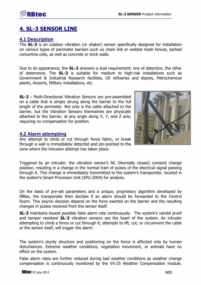
SL-3 - Multi-Directional Vibration Sensors are pre-assembled on a cable that is simply strung along the barrier to the full length of the perimeter. Not only is the cable attached to the barrier, but the Vibration Sensors themselves are physically attached to the barrier, at any angle along X, Y, and Z axis, requiring no compensation for position.
4.2 Alarm attempting Any attempt to climb or cut through fence fabric, or break through a wall is immediately detected and pin-pointed to the zone where the intrusion attempt has taken place.
Triggered by an intruder, the vibration sensor's NC (Normally closed) contacts change position, resulting in a change in the normal train of pulses of the electrical signal passing through it. This change is immediately transmitted to the system's transponder, located in the system's Smart Processor Unit (SPU-2004) for analysis.
On the basis of pre-set parameters and a unique, proprietary algorithm developed by RBtec, the transponder then decides if an alarm should be forwarded to the Control Room. This yes/no decision depend on the force exerted on the barrier and the resulting changes in pulses received from the sensor itself.
SL-3 maintains lowest possible false alarm rate continuously. The system's vandal proof and tamper resistant SL-3 vibration sensors are the heart of the system. An intruder attempting to climb a fence or cut through it; attempts to lift, cut, or circumvent the cable or the sensor itself, will trigger the alarm.
The system's sturdy structure and positioning on the fence is affected only by human disturbances. Extreme weather conditions, vegetation movement, or animals have no effect on the system.
False alarm rates are further reduced during bad weather conditions as weather change compensation is continuously monitored by the VX-25 Weather Compensation module.

SL-3 SENSOR Prodact information
-----------------------------------------------------------------------------------------------------------------
RBtec PI July-2013 6/21
The VX-25 automatically adjusts the system sensitivity for varying wind conditions rain or hail.
The SL-3 system continuous coverage of a specific perimeter area including gates, without blind spots, detects intrusion attempts by any of the following methods:
Climbing
Cutting with wire cutters or saw
Physical deformation of fence (unraveling)
Damage to the electronic system
The SL-3 system will detect any vigorous or careful climber having a weight of 45kg or more within 0 - 60 seconds.
Extensive performance tests of the SL-3 system have resulted in high scores of Pd (Probability of Detection) at 98% and better.
The sensors are factory pre-assembled on the sensor cable at intervals of approximately 3 meters (9.8 ft.) between sensors. This represents an industry standard of approximately one sensor between two fence posts.
The sensor housing is made of a unique type of high resistance plastic material which provides protection against UV radiation, chemicals, humidity and mechanical impacts.

SL-3 SENSOR Prodact information
-----------------------------------------------------------------------------------------------------------------
RBtec PI July-2013 7/21
The housing undergoes ultrasonic welding process which completely seals the unit from dust and moisture.
The sensor contains two separate internal chambers:
1. The detection chamber 2. The connection chamber
The detection chamber contains a gold plated; 10-point contact mechanism mounted on a printed circuit board and is designed to provide 10 electrical contacts. The combination of contacts provides a super sensitive detection capability and an electro-mechanical filter which filters out frequencies below 1000Hz (normally originating in environmental disturbances such as wind and rain).
Any intrusion attempt, such as; climbing, wire cutting, physical deformation or unraveling of the fence fabric - will generate vibrations which will cause the internal contacts to change their positions and open the NC (Normally Closed) circuit for a very short time (approximately 0.002 seconds). These changes are converted into electrical pulses which are processed by a transponder unit which subsequently produces the necessary alarm signal.
The connection chamber consists of the serial connection between each sensor and the sensor cable.
The sensor has self-aligning capabilities which enables mounting at any X, Y or Z-axis angle and provides accurate response to vibrations.
The sensor is completely maintenance free, requiring no field calibration.
Specifications: Operating temp.: -45°C (-49°F) to +70°C (+158°F). Capsule Enclosure: Injection molded high resistant plastic Size of capsule: 69mm x 42mm x 30mm (2.7” x 1.65” x 1.18”) Weight: 50 gr. Comm Cable: Shielded AWG gauge six wires cable. Life expectancy: 10 years field operation

SL-3 SENSOR Prodact information
-----------------------------------------------------------------------------------------------------------------
RBtec PI July-2013 8/21
5. FIELD EQUIPMENT
5.1 Sensor Line Termination Board (SLT) The Sensor Line Termination Board (SLT) is used to connect Sensor Line cables between zones. The use of standard wire jumpers enables quick field connection of all zones without the need for cumbersome soldering.
A standard 6 x 6 cm (2.3" x 2.3") PCB holds 2 standard 8 point block screw terminals, 6 jumper pin strips and a resistor to form a simple quick Sensor Line installation, maintenance and troubleshooting solution.
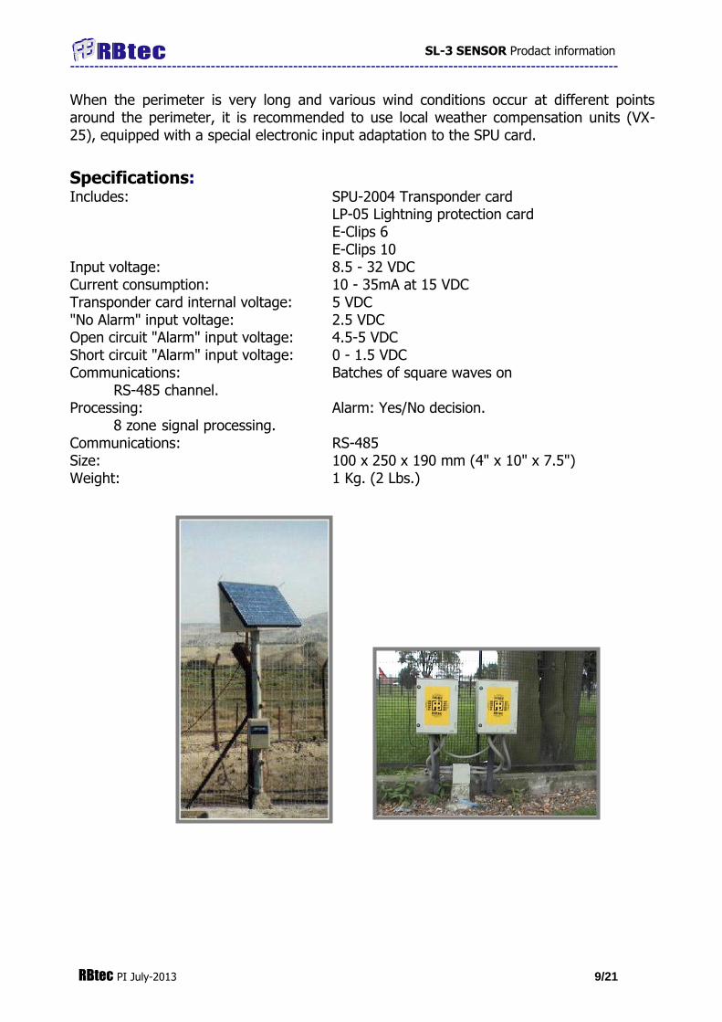
5.2 SPU - Smart Processing Unit The system's field sensors are polled for pre-alarm recognition and analysis in the Smart Processing Unit (SPU-2004) which analyzes and transmits signals from the system's field sensors to the central Control Interface Unit (IA-6500). The weather proof (IP 65) plastic box contains a Transponder Card (SPU-2004), Lightning Protection card (LP-05) with optional addition for lightning suppressor units (E-Clips) to protect all inputs and outputs.
One Transponder card (SPU-2004) normally covers 8 zones and is installed at a convenient location in the fence area. Up to 16 Smart Processing Units (SPU-2004) may be connected to one Control Interface Unit (IA-6500) in the control center, enabling full coverage of 128 zones by a single IA-6500 Control Interface Unit.
The Transponder is a microprocessor card, which analyses and accumulates the output signals of the shock sensors on the sensor line and when an alarm condition is encountered it informs the Control Interface Unit accordingly.
Pre-set system characteristics are continuously compared with current conditions. Any change in current conditions such as pressure exerted on a given fence section, vibrations of the fence, the cable or a sensor, an attempt to cut the cable, vibrations resulting from an attempt to break through a wall; all trigger a comparison process in the Transponder card.
Based on the extent of ‘change’ from pre-set conditions to current, the microprocessor in the Transponder card then decides if the alarm is true or false, and if the change requires triggering the alarm.
Fully protected against EMI/RFI interferences, the Transponder communicates with the Control Interface Unit via RS-485 communication protocol, continuously monitoring the communication cable continuity, and signals from the Sensors on the barrier.
For optimal response effect, each Transponder covers and processes signals from 8 alarm zones. Alarm zones are normally assigned at 100 Meters (330') intervals, so that only one Transponder is required for each 800 meters (2640') of perimeter segment.
The microprocessor in the Transponder card may be re-programmed during system operation so that the status (Armed/Disarmed) and sensitivity of zone may be changed according to operational conditions. (i.e., re-programming may be required as a result of changes that occurred in these parameters during bad weather conditions, etc.)
SL-3 SENSOR Prodact information
-----------------------------------------------------------------------------------------------------------------
RBtec PI July-2013 9/21
When the perimeter is very long and various wind conditions occur at different points around the perimeter, it is recommended to use local weather compensation units (VX-25), equipped with a special electronic input adaptation to the SPU card.
Specifications: Includes: SPU-2004 Transponder card LP-05 Lightning protection card E-Clips 6 E-Clips 10 Input voltage: 8.5 - 32 VDC Current consumption: 10 - 35mA at 15 VDC Transponder card internal voltage: 5 VDC "No Alarm" input voltage: 2.5 VDC Open circuit "Alarm" input voltage: 4.5-5 VDC Short circuit "Alarm" input voltage: 0 - 1.5 VDC Communications: Batches of square waves on
RS-485 channel. Processing: Alarm: Yes/No decision.
8 zone signal processing. Communications: RS-485 Size: 100 x 250 x 190 mm (4" x 10" x 7.5") Weight: 1 Kg. (2 Lbs.)

SL-3 SENSOR Prodact information
-----------------------------------------------------------------------------------------------------------------
RBtec PI July-2013 10/21
5.3 Meteorological Unit In ordinary perimeter alarm systems fence movement resulting from strong winds, rain and hail may cause sensor movement and The VX-25 Weather Compensation Unit is a unique detection unit designed to compensate system sensitivity automatically for disturbances caused by changing weather conditions such as wind, rain or hail.
Wind velocity is converted to analog DC voltages. Rain and Hail forces are converted to digital pulses.
The VX-25 adjusts the system through its own interface unit. Therefore, wind velocity measured at the 3 Cup manometer and rain or hail pounding on its 3 concave sensing discs, are translated into a “pseudo-alarm” signal and fed into the field Transponder card (SPU-2004) temporarily resetting the system sensitivity thresholds to a new “Zero” position.
The Smart Processing Unit (SPU-2004) can therefore distinguish between weather related signals, and authentic alarm signals.
Any intrusion attempt during such conditions would vibrate the SL-3 Sensors, causing electronic signals to deviate from the system’s new temporary “Zero” position and trigger an alarm.
With the VX-25 unit, only true alarms are now triggered, and the nuisance alarm problem resulting from changing weather conditions is eliminated.
5.3.1 Rain Sensor The rain sensor discs and shock sensors are vibration sensing units whose function is to detect the vibrations caused by rain or hail drops. These vibrations are translated into electronic signals and transmitted to the field Transponder card (SPU-2004).
5.3.2 Wind Sensor A 3 cup manometer is mounted at the top of the center post holding the rain sensor discs. This wind vain manometer produces a voltage frequency which fluctuates with the changes in wind speed. This frequency is converted to electronic signals and transmitted to the Control card.
transforms the AC frequency sent by the wind manometer on the VX-25 Weather Compensation Unit to a DC analog voltage relative to the wind speed.
Specifications: Measures wind speed up to: 100 mph. Power consumption: 12 VDC 5mA

SL-3 SENSOR Prodact information
-----------------------------------------------------------------------------------------------------------------
RBtec PI July-2013 11/21
6. CONTROL ROOM COMPONENTS
Monitoring and control of the VIDALERT system is accomplished at the control room or guard booth by means of a Control Interface Unit (IA-6500), standard server client computer, SVGA monitor, and the usual PC accessories.
6.1 IA-6500 Control Interface Unit The IA-6500 Control Interface Unit is designed to receive signals from field transponders SPU-2004 and transmit the processed data into the system's central computer.
The IA-6500 contains the Central Control Card, a Back-Up Control Card, a Lightning Protection Card, and a Power Supply.
Additional IA-6500 Control Interface Units may easily be added for larger perimeters using additional hardware to interface between several IA-6500 Control Interface Units and the Central Computer.
The IA-6500 Smart Control Interface Unit has fully automatic back-up capability in case of PC or other hardware failure. In the event of PC hardware or software failure, the IA-6500 automatically takes command of the system ensuring secure operation without interruption.

SL-3 SENSOR Prodact information
-----------------------------------------------------------------------------------------------------------------
RBtec PI July-2013 12/21
Fully automated, the IA-6500 includes two internal control units, a full backup software program, an active LCD display, control panel and a rechargeable battery, all mounted on a standard 19" rack for easy installation.
A 15 VDC Power Supply installed in the unit serving both the IA-6500 and the Smart Processing Unit (SPU-2004) in the field.
Although inactive during normal system operation, the IA-6500 is always connected to the system in an ‘ON-GUARD’ mode. When PC failure occurs, the IA-6500 automatically takes control and continuous system operation is maintained through its on-board control panel.
6.1.1 Control Display Features
Key Function
Menu/Enter Move between menu options and confirm selections.
ESC Go to previous screen, cancel selections and move out of program to alarm screen.
UP Change values up
DOWN Change values down
ACK Acknowledge alarms and silent annunciator
DEL Delete alarm after acknowledge

SL-3 SENSOR Prodact information
-----------------------------------------------------------------------------------------------------------------
RBtec PI July-2013 13/21
6.2 VIDALERT software configuration The VIDALERT system software is designed to operate under the Microsoft Windows operating system and uses the full power of Windows graphic capabilities.
The VIDALERT software program controls the complete VIDALERT system, enabling control and management via a single keyboard and monitor.
The PC monitor displays the present status of the entire perimeter in real time. The main screen displays a color graphic map of the secured site, clearly showing the perimeter zones in different colors. When an alarm is triggered the relevant zone will start blinking in red and an audible alarm will sound. From the main screen, the operator may use different keys to move through the system’s functions such as:
Changing of zone sensitivities. Changing of ‘Arm/Disarm’ status. Changing of the system ‘Time/Date’. Password enrollment for access authorization to system controls. Data bank access.
Immediate help on current screen, quick help panel.
6.3 VIDALERT Software Program VIDALERT unique sensing and intrusion detection capabilities are enhanced by a PC based, active color graphic site map display, a series of screen display keyboard controlled function keys and a variety of communication and response capabilities to form a complete perimeter protection system.
Alarms are presented on the active color graphic site map as a flashing zone and announced by pre-recorded synthesized computer voice or a beeping sound. In addition, it can activate electronically integrated systems such as CCTV and auxiliary response equipment such as sirens, floodlights and automatic gates and barriers for the identification and capture of intruders.
From the perimeter map, the user has a complete overview of the entire protected site status including system ‘Arm/Disarm’ status.
A standard PC computer may be used with the system.

SL-3 SENSOR Prodact information
-----------------------------------------------------------------------------------------------------------------
RBtec PI July-2013 14/21
Data displayed on the screen (but not limited to):
Graphic site maps. Event screens. Status change screens. Sensitivity change screens.
Historical data screens. Hard copy and printout control. Built-in help screens. Voice announcement controls. Special customers’ tailored screens. 6.3.1 Alarms & Commands The Central Control is normally maintained in "monitoring" status. When an alarm is received, the system monitor indicates "alarm" status and the affected zones of the perimeter are immediately shown. Alarms are visually displayed and audibly announced by a ‘voice recording’ or beep, enhancing security personnel reaction. All alarm commands and events are recorded and stored for analysis and hard copy report printing.
The Control Interface Unit monitors and controls all alarm zones, as well as additional devices such as lighting, CCTV, horns, sirens and other physical response auxiliary devices. These devices are controlled and activated through the Smart Processor Units (SPU-2004).
Eight relay outputs per transponder are available for linking the Control Interface Unit with remote devices.
6.3.2 Alarm Communications, Analysis And Response VIDALERT’s unique sensing and intrusion detection capabilities are enhanced by a PC based, customizable ‘Active Color, Graphic Site Map Display’, a series of screens display keyboard controlled functions and a variety of communication and response capabilities, to structure an all inclusive perimeter defense system.
Alarms are presented on the Active Color Graphic Site Map, as a "flashing" zone and announced by pre-recorded, synthesized computer voice or a beeping sound.

SL-3 SENSOR Prodact information
-----------------------------------------------------------------------------------------------------------------
RBtec PI July-2013 15/21
Signals can then be transmitted to mobile units or to remote stations through RF radio, cable, or telephone /cellular communications.
In addition, activation of electronically integrated systems and response equipment such as; CCTV, sirens, floodlights, automatic gates and barriers can be initiated in order to locate, identify and capture would-be intruders.
6.3.3 Main Screen - Site Map From the perimeter map the user has a complete overview of the entire perimetric zone status, including the Alarm Status (whether there is an alarm or not) and Zone Arm Status.
6.4 Security Software VIDALERT’s Custom-Site Graphics, human interface engineering was developed with the end user in mind.
Customized software provides an Active Color Graphic Site Map Display of the actual site with overlaid perimeter zones on the system's monitor. 'Zoom-In' view Info Screens, for critical areas located close to an alerted zone; enhance the use of the Graphic Site display.
Keyboard operated, screen displayed function keys, including "Help", enable complete and user friendly system controls by security personnel at the control center.
The software program includes flashing instructions, clear and simple icons and one step movements from window to window (keyboard/mouse).
Although assignment of function keys are customized to meet the specific requirements of each specific installation, RBtec's more than 20 years of extensive field experience has developed a standard set of pre-programmed function key assignments to provide an optimal configuration applicable to most installations.
6.5 Central Computer & Monitor The system is running on server client configuration. The server is manage, monitor receives stores and displays alarm messages from the IA-6500 to enable complete visual & audio perimeter monitoring and response by security personnel. The clients are operating stations
Equipped with customized Active Color Graphics Site Map Display capabilities through fully customized software, the computer's monitor displays actual site graphic maps, including perimeter layout, zone locations, buildings, floor layout, rooms, and other site facilities as needed, depending on site resolution required by the customer.
All alarm signals received from VIDALERT Sensors (or other sensors interfaced with the system) are processed, displayed on the Active Graphic Site Map Display Monitor and audibly annunciated through a synthesized computer voice.
Data displayed on the screen includes (but is not limited to): graphic site maps, events, status change, sensitivity change, historical data base, hard copy printout controls, built-in help and voice announcement controls.

SL-3 SENSOR Prodact information
-----------------------------------------------------------------------------------------------------------------
RBtec PI July-2013 16/21

SL-3 SENSOR Prodact information
-----------------------------------------------------------------------------------------------------------------
RBtec PI July-2013 17/21
7. CONFIDENTIAL SITE QUESTIONNAIRE
PURPOSE The purpose of this confidential site questionnaire is to enable our initial evaluation of specific site compatibility for the installation of our INTRUDALERT system. It is very important that all data is completed at the highest degree of accuracy, so that a realistic proposal which will meet your operational requirements can be prepared.
Estimated quotation will be based on knowledge acquired from site questionnaire/client. RBtec reserves the right to amend future quotations based on actual information. Our questionnaire covers details concerning several major areas of concern when INTRUDALERT is installed:
A. A General Security Profile B. Physical Dimensions. C. Current perimeter protection fence details. D. Topographic & natural environment conditions. E. Current equipment installation F. Electrical environment. G. Operational access & off site activities. H. Roads, Trains, Bridges etc. I. General comments. All information provided herein will be kept in strictest confidence.
A. A General Security Profile
1. Facility general description (Type, purpose, etc.)
___________________________________________________________________
___________________________________________________________________
___________________________________________________________________ 2. Threat scenario: (Please check appropriate item)
__Vandalism. __Theft __Espionage __Personal __Terrorism
__Other_____________________________________________________________
3. Expected Intruder sophistication: __Casual __Experienced __Professional
4. Response type: __Lights/Sirens __Guard on Duty __Private Police
__Employee on premises __Company radio car __Public Police
__Special tactics __Other

SL-3 SENSOR Prodact information
-----------------------------------------------------------------------------------------------------------------
RBtec PI July-2013 18/21
5. Facility secured time periods: __24 Hours __16 Hours __8 hours __Day
__Night Comments:____________________
B. Physical Dimensions.
Protected area: Total perimeter length_______________________ fit/ m'
C. Current perimeter protection fence details.
Perimeter fencing: __Diamond Chain Link fence __Welded mesh fence
__Barbed wire __Stainless steel
__Plastic coated __Galvanized
__Razor tape concertina
__Other: (Please detail)_____________________________________
Fence physical characteristics:
__ Fence height___________________________________________
__Type of fence poles:______________________________________
__Distance between fence poles:______________________________
Note: Please use additional drawings or pages for additional fence details.
(Heights, pole types, distances between poles, etc.)
Fence upper sections: __Straight __3 Barbes __Razor type
__Barbed wire __Concertina Coil
Fence condition: __New __Old __Good __Poor
__Loose __Damaged __None
Additional comments:______________________________________________________
Note: Fence wire strength should be at least 45 Kgs/mm hardened, with thickness of at
least 3mm 0.
Do access points for digger or slitter exist along the fence? __YES __NO
Additional Physical fence protection: __Barbes __Razor Ribbon
__Multiple fencing __Concertina coil
Gates: Number of gates_______ Gate width: #1___ #2___ #3____ #4____
Types: Wing (Number)______ Sliding (Number)_____ Other_______
D. Topographic & natural environment conditions.

SL-3 SENSOR Prodact information
-----------------------------------------------------------------------------------------------------------------
RBtec PI July-2013 19/21
Terrain: __Hilly __Flat __Steep slopes __Rivers/Streams
__Obstructions __Landscaping
__Other_________________________
Surface: Ground structure: __Soft __Rocky __Sand __Gravel
__Other______________________________________
Ground cover - Asphalt: Existing __To be laid: Thickness required:
Ground cover - Cement: Existing __To be laid: Thickness required:
Combination -Existing or required:__________________________________
(Please note on layout grid).
Climate & normal local weather conditions:
__High winds __Blowing debris __Hail __Sea spray\Salt air
___Frequent electrical storms (Lightning) __Desert heat __Extreme cold
__Wide temperature variations ___Other___________________________.
External nuisance elements: __Flying birds __Flying debris
__Vandals __Domestic animals __Gophers, other small animals, rats, mice
etc.
E. Equipment installation Item Present Future Distance from sensor line
Sprinklers
Water
Gas
Compressor(s)
Vibration equipment
Other
F. Electrical environment
RF Interference: __Unknown __None __Known:
(Please describe so that filters for RFI rejection can be pre-installed)
_________________________________________________________________________
_______________________________________________________________________
G. Operation access & Off site activities.
Normal conditions when system is armed: __Quiet __Some activity
__Heavy traffic __Aircraft __Nearby running power equipment
__Other_____________________________
Access required when system is armed: __YES __NO

SL-3 SENSOR Prodact information
-----------------------------------------------------------------------------------------------------------------
RBtec PI July-2013 20/21
Specify zones:______________
Activities outside the property:
NORTH SIDE:
SOUTH SIDE:
EAST SIDE:
WEST SIDE:
H. Roads, Bridges, Trains, etc.
From nearest
freeway
From nearest
road
From nearest railway
tracks
Distance:
Railway track type:
Main Spur Other
I. General comments.
Are photos of the site available: ___YES __NO
Additional comments:
J. Contact Information/Misc Site Info.
Company Name:___________________________________
Name:____________________________________________
Address:__________________________________________ _________________________________________________
Phone:_________________________
Fax:___________________________
Email:__________________________
Site Location (Name/address):________________________ _________________________________________________
_________________________________________________
_________________________________________________
Date:_________________________

SL-3 SENSOR Prodact information
-----------------------------------------------------------------------------------------------------------------
RBtec PI July-2013 21/21
This document has been written and produced by RBtec to provide the reader with as much technical and other information as possible about RBtec its products and its services. Copying any of its contents without prior permission from RBtec is strictly prohibited. This information is provided for the purpose of initial evaluation of RBtec's products and services. In keeping with RBtec's policy of continuous development, RBtec reserves the right to alter these specifications without notice.