pi 25-6 - candu owners group library/20051007.pdf · 2011-09-16 · pi 25-6 the mollier diagram for...
TRANSCRIPT

PI 25-6
Tur.bine and Auxiliaries -'Course PI 34
THE MOLLIER DIAGRAM ·AND THE TURBINE PROCESSES
Objectives
1. Sketch a Mollier diagram from memory. Label the following on yoursketch:
(a) constant enthalpy lines(b) constant entropy lines(c) saturation line(d) constant temperature lines(e) constant pressure lines(f) constant moisture content lines(g) constant degree of superheat lines
2. On the sketch of a Mollier diagram that you have drawn, illustrate theseturbine processes:
(a) expansion in the high pressure turbine(b) moisture separation(c) reheat(d) expansion in the low pressure turbine
3. Explain how moisture separation and reheat each:
(a) increase the enthalpy of the steam at the LP turbine inlet(b) reduce the moisture content of the steam at the LP turbine outlet
4. Define throttling and, using a Mollier diagram, explain how throttling ofthe steam supplied to the turbine affects:
(a)
(b)
the pressure, temperature and moisture content of the steam at theturbine inletthe amount of heat which can be converted into mechanical energy bythe turbine.
April 1990 ITPO.Ol
PI 25-6
Mollier Diagrams and The Turbine Set
This module deals with the turbine process. When youhave finished the module, you should be aware of the majorequipment of the turbine set and you should be able to showthe turbine process on a Mollier diagram.
Mollier Diagrams•
The Mollier diagram is a very useful tool. It can beused to depict the various processes associated with the turbine set. It may also be used quantitatively for variouscalculations. Your consideration of Mollier diagrams in thiscourse will be limited to a qualitative look at the turbineset.
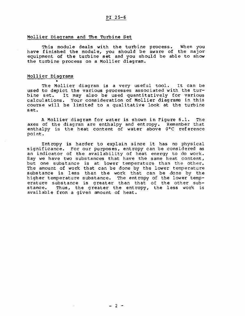
A Mollier diagram for water is shown in Figure 6.1. Theaxes of the diagram are enthalpy and ent ropy. Remember thatenthalpy is the heat content of water above OOC referencepoi nt.
Entropy is harder to explain since it has no physicalsignificance. For our purposes, entropy can be considered asan indicator of the availability of heat energy to do work.Say we have two substances that have the same heat content,but one substance is at lower temperature than the other.The amount of work that can be done by the lower temperaturesubstance is less than the work that can be done by thehigher temperature substance. The entropy of the lower temperature substance is greater than that of the other substance. Thus, the greater the entropy, the less work isavailable from a given amount of heat.
- 2 -
EnthalpykJ/kg
PI 25-6
EntroPY,kJ/kg °c
Figure 6.1
- 3 -
PI 25-6
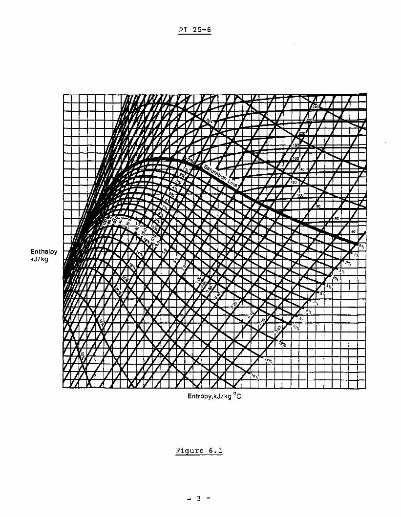
The Mollier diagram for water deals with three states ofwater: saturated steam, wet steam, and superheated steam.On Figure 6.2, the darker line marked saturation linerepresents saturated steam at diff erent conditions oftemperature and pressure. Superheated steam is representedabove the saturation line. Wet steam is represented belowthe saturation line.
EnthalpykJ/kg
EntroPY,kJ/kg °c
Figure 6.2
- 4 -

PI 25-6
Besides enthalpy and entropy, there are other variablesshown on a Mollier diagram.
Figure 6.3 shows a Mollier diagram with constant temperature lines indicated.
EnthalpykJ/kg
oEntroPY,kJ/kg C
Figure 6.3
- 5 -

PI 25-6
Figure 6.4 shows constant pressure lines. Note that theconstant pressure lines and constant temperature lines areparallel in the wet steam region, but not in the superheatedsteam region. This is because for saturated conditions(e.g. wet steam) the temperature remains constant at constantpressure as heat is added. For conditions which are not atsaturation (e.g. superheated steam) the temperature does notremain constant as heat is added at constant pressure.
EnthalpykJ/kg
EntroPY,kJ/kg °c
Figure 6.4
- 6 -
PI 25-6
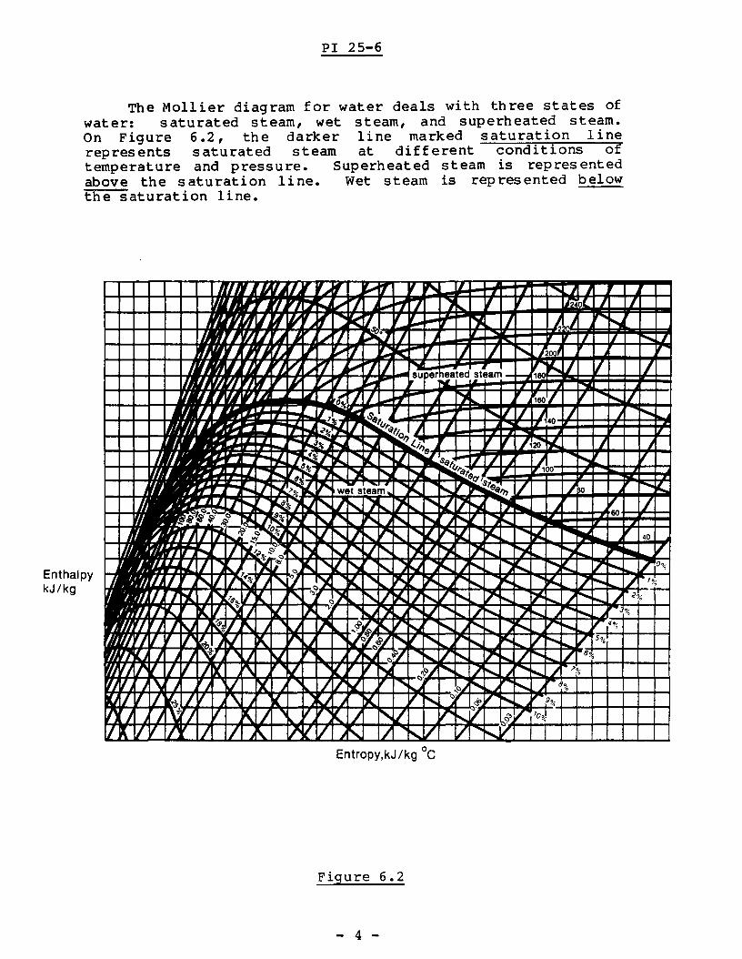
Figure 6.5 shows constant moisture content lines. Theseshow wet steam at different temperatures and pressures thathave the same percent moisture.
EnthalpykJ/kg
EntroPY,kJ/kg °c
Figure 6.5
- 7 -
PI 25-6
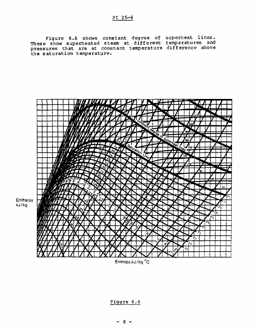
Figure 6.6 shows constant degree of superheat lines.These show superheated steam at different temperatures andpressures that are at constant temperature diff erence abovethe saturation temperat~re.
EnthalpykJ/kg
EntroPY,kJ/kg °c
Figure 6.6
- 8 -
PI 25-6
--. Answer the following question in the space provided,then check your answer with the II TEXT ANSWERS II •
6.1) From memory, sketch and label a Mol1ier diagram forwater. Your labels should include the following:
(a) constant enthalpy lines(b) constant entropy lines(c) saturation line(d) constant temperature lines(e) constant pressure lines(f) constant moisture content lines(g) constant degree of superheat lines
- 9 -

PI 25-6
The Turbine Process
The turbine set of a large CANDU unit is shown in Figure6.7. Note that this diagram is somewhat simplified forclarity.
STEAMFROM
BOILERS ..._
MOISTURESEPARATOR
DRAINS TOFEEDHEATING
HIGH PRESSUREI--------ITURBINE
LOW PRESSURETURBINE
STEAMFROM
BOILERS
STEAMTO
CONDENSER
Figure 6.7
- 10 :

PI 25-6
Saturated steam at about 250°C and 4 MPa( a) comes fromthe boilers to the high pressure (HP) turbine. As the steamflows through the turbine, its pressure and temperaturedrop. The effect of these changes is to turn the turbineshaft - i.e. some of the heat energy of the steam is converted into shaft mechanical energy.
As the steam supplied to the turbine is saturated, theheat which is extracted from the steam is a portion of thelatent heat of vaporization. The effect of this is that thesteam starts to condense and as it flows through the turbinemore and more moisture is produced. Finally, at the outletof the HP turbine, the steam typically has a moisture contentof about 10% and pressure of about 800 kPa(a) with a corresponding saturation temperature in the order of 170°C. Thispart of the overall process is shown (from A to B) on Figure6.8
EnthalpykJ/k~
Entropy,kJ/kg C
Figure 6.8
- 11 -

EnthalpykJ/kg
PI 25-6
Why is the stearn taken out of the turbine at thispoint? The reason lies in the moisture content. At moisturelevels above about 10%, erosion caused by the impingement ofthe liquid droplets on moving parts becomes unacceptable.The stearn must have the moisture removed before it can beused to produce more power. This is accomplished in themoisture separator. Liquid is physically removed from vaporin the separator. The stearn at the moisture separator outletis essentially saturated at about 170°C and 800 kPa(a). Theseparation process is shown (from B to C) on Figure 6.9.
EntroPY,kJ/kg C
Figure 6.9
- 12 -

PI 25-6
Note that the stearn enthalpy has increased. How canthis be true? Has any heat been added to the stearn to increase its enthalpy? The answer is no, no heat has beenadded. The enthalpy has gone up because the moisture hasbeen removed. Remember that enthalpy is heat content per kgof water above O°C. The enthalpy of wet stearn is a weightedaverage of saturated liquid enthalpy and saturated stearn enthalpy. If we remove the liquid from the wet stearn, the heatcontent per kg of the fluid that remains will be higher.However, there will be fewer kilograms of fluid after separation than before. Thus, the total heat contained in thestearn leaving the moisture separator is certainly smallerthan that in the stearn entering, since some heat is containedin the water separated by the moisture separator.
- 13 -
PI 25-6
--. Answer 6.2 before you proceed.the one in the "TEXT ANSWERS".
Check your answer with
6.2) Explain how moisture separation increases the steamenthalpy of the steam exiting the HP turbine.
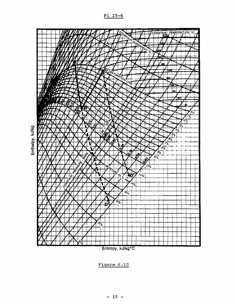
The steam could now enter the LP turbine and generatemore mechanical energy. The problem with this is thatcondensation would start immediately, and before the steamcould reach the design exit conditions (i.e. 30°C and 4kPa(a) its moisture content would be completelyunacceptable. In fact, if you look at Figure 6.10 and followthe notted line from C (moisture separator exit conditions)to D' (30°C and 4 kPa(a», you will see that the moisturecontent will be about 15%. This value I however, would bemuch smaller than the moisture content of the steam at the LPturbine exhaust if no moisture separator were used so thatsteam could flow from the HP turbine directly to the LPturbine. Such a process is shown on Figure 6.10 as Line B-D"and you can see that the moisture content would be about 21%.
- 14 -
PI 25-6
~f ~~ ~~ ~ V ' ~
IJ .~ "" ~.J I ~..-I' I ~ ~ II.. if ...... t--... ,/ I~ 1 ~~~~ I ~I':II / J ~
,"Vi 1/ ~ /17 IV 1/ '" IV J "') V
/I/V } V II '~'~-i--t-1~++-H++-+-!1 ++-t-+-+-+-W-l--IIV // "'\/ V V 1.1 % , !
IA V IV' / / /
VV j /"-. .J\ V ~~....~~-rH--rH--t-t-t-++f-++H+-H4--t--W-t--U
Entropy, kJ/kgOC
Figure 6.10
- 15 -
PI 25-6
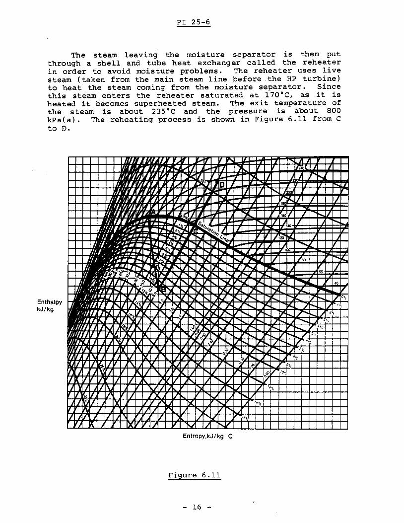
The steam leaving the moisture separator is then putthrough a shell and tube heat exchanger called the reheaterin order to avoid moisture problems. The reheater uses livesteam (taken from the main steam line before the HP turbine)to heat the steam coming from the moisture separator. Sincethis steam enters the reheater saturated at 170°C, as it isheated it becomes superheated steam. The exit temperature ofthe steam is about 235°C and the pressure is about 800kPa(a). The reheating process is shown in Figure 6.11 from Cto D.
EnthalpykJ/kg.
rN 'IN, I ,. '( 'rT ~IT '( ~I .II ,-I
j rl. vJ ""'" ~I J~ 1"1 7 ')~ If If Imol J I
~ ~IU f{ ......~7. II ,
"""" rr "JIll I ) ~J Nrf r~ J / r"1 j ~:J J 0 II II f""'oo. I
ry Jlj 'J r/.r , ~7 ~ II II " I'.. )200
'.oil j ~jv,~ 7 ;..- 7 I~ Dl IF I(..17 V 1/
" l 1# r/l ~.., I leo
rgl'II J.,~ I 11_"'''- ~ / 7 ..... ....... II
%160
~~-..~~ Ir; ...... / 1 ~40 / j ~
~t. IL...... ~~~ i"--=~tio J.....~% Il-o. I'-o.l ~(,I;' II I /1~ o£ I j
1....,~%7~ ...... £I'J ....~ I f I ..... I-::JZ7 ..... ~ ~ ~ ~ ...... 100
"?& 11,,-~,..,,~7 ~~,. " .....1£ ..... (.. ........ I' ~ iJ / leo .......~- - AI 7' ..... l'7"rj ........ l./ '" 7~ 7- """
...... .L 7- ...... ., ....... J, /10- ~~.r;~. ~~
~.I ,II' " ""
60
" ) '" ...... J ..... ..... .....10-
'I J FrJo~ '~~l!' j '",..
'- ....... £. ,... £ ><. .....~ ......~ ,- 40
-""",; F ~c' ~. 'oJ '"J , )( / ")( ~ ....... ~ ~ ;,11IIII .... ,""'--% '"__ '-'- 1 ~;. ",,, ......, ~ '- ..... V """"-. ) ~ ..... '- :--.., ""-.. 7- ...... 7 0 0
0
'11 '/1'"I~% j,7 "')( IC.. ...... ~ )' roo., .... """"'iiiC 7 ...... / ".
'"IJ 7"'l.. ~/''o 7'l ""'." ",)C: '" /'~ 7 ......./ ..... "7- ...... )i:; ..... ~"- ..... ,j <'%
7"'" If.. / ~ 7 ~ ~ . )C ......v ...... ~ ...... "7 ..... ....... Jo.,
rl J I u J~ IT '\: ) .J ~lX~ '" ~ ....... J ..... "- 7'" ...... .,~;
rJ 1/ II ~ JV X. .... 0.) Y",~LI ......., I""'. ,..", ~ 10.... / ...... 10.... V $%
rJ £ J j VI J V 11II.. J ) 'oJ ",0/ '"1/~ i7" .... / ..... 10.... 1/ ·8%
II i~ 'I I II I Ir "- v I( I N ",~II" ] ~ ~ ....... ...... I .....%
If J" J J V Y. ) / /' ttL ...... ,'" I'. "'- 8%
II If II ('OJ. II I ,) il .I J )(. II r--.. ",. ,.
" 9%<!>J ) \f' 'I II ~ / , II " <. / ....... l/ 'r' i"o.. '7 "," / Tool
II( I II I) 1 / \. II''( 1/ J "- j '"V 1/ .... ...... VJ ~ J I\. f7 ~1/ /
,~ / ....... 'J / '2°;-
J~ ~1/ " IJ' J ) 1/ ..... II v J -..,.. ./1/ J Y 1/ / 'r' J I)( ...... ~ 14%
I 1\ / ~ J 7 7 .... I :"...V / ....... J
II J r j / I , / / ...... ./ ,. '5%
II ~ I IX 7 7 -7 / V I ...... /
EntroPY,kJ/kg C
Figure 6.11
- 16 -

PI 25-6
-.. Answer question 6.3 in the space provided I then checkyour answer with the "TEXT ANSWERS".
6.3) Explain how reheat increases the enthalpy of the steamcoming from the moisture separator.
- 17 -
EnthalpykJ/kg
PI 25-6
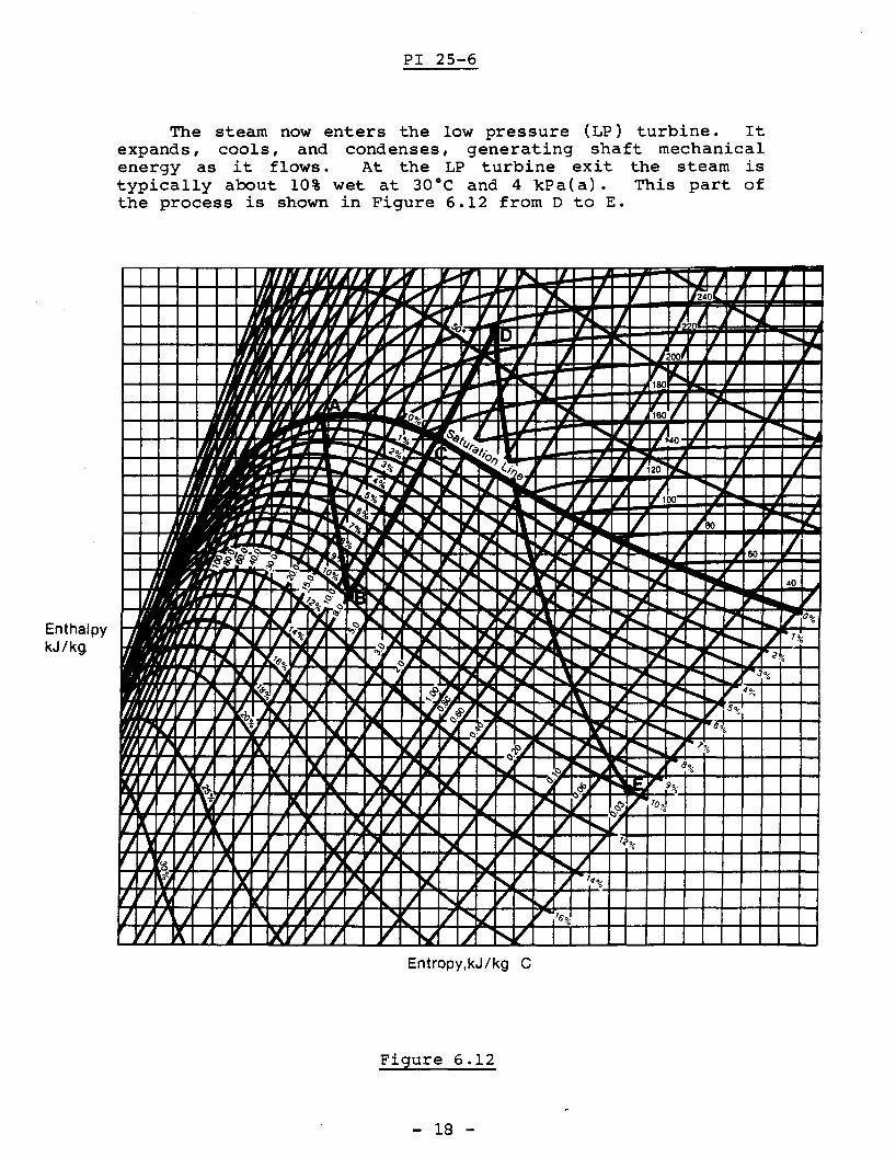
The steam now enters the low pressure (LP) turbine. Itexpands, cools, and condenses, generating shaft mechanicalenergy as it flows. At the LP turbine exit the steam istypically about 10% wet at 30°C and 4 kPa(a). This part ofthe process is shown in Figure 6.12 from D to E.
Entropy,kJ/kg C
Figure 6.12
- 18 -

PI 25-6
~ Answer the following question in the space provided,then check your answer with the one in the "TEXT ANSWERS".
6.4) Sketch a Mollier diagram from memory. On it, show theoverall turbine process, including:
(a) high pressure turbine(b) moisture separator(c) reheater(d) low pressure turbine
6.5 On the Mollier diagram you have already sketched, showhow the moisture separator and reheater reduce the moisture content of the steam at the LP turbine outlet.
- 19 -

PI 25-6
Throttling
This is a process where a compressible fluid expandsfrom one pressure to a lower pressure but no mechanical workis done. Although, throttling occurs to a certain extent inany pipeline (especially if it is long), partially openvalves are one place where the process is most noticeable.
When throttling takes place, the enthalpy of the fluidremains constant. This is true because:
(a) no mechanical work is done by the fluid,(b) there is no heat loss because the flow occurs at high
speed and there is no time for heat to pass through thevalve casing or pipe walls. Often they are lagged withthermal insulation which makes heat transfer even moredifficult.
Since the enthalpy of a throttled fluid does not change,throttling can be shown on a Mollier diagram as a horizontalline. Figure 6.13 shows throttling of wet steam. As you cansee, the steam pressure and temperature are reduced. Themoisture content of the steam is reduced as well and, ifthrottling is sufficiently large, superheated steam can beproduced.
EnthalpykJ/kg
EntroPY,kJ/kg C
Figure 6.13
- 20 -
PI 25-6
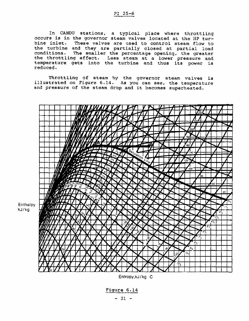
In CANDU stations, a typical place where throttlingoccurs is in the governor steam valves located at the HP turbine inlet. These valves are used to control steam flow tothe turbine and they are partially closed at partial loadconditions. The smaller the percentage opening, the greaterthe throttling effect. Less steam at a lower pressure andtemperature gets into the turbine and thus its power isreduced.
Throttling of steam by the governor steam valves isillustrated on Figure 6.14. As you can see, the temperatureand pressure of the steam drop and it becomes superheated.
EnthalpykJ/kg
EntroPY,kJ/kg C
Figure 6.14
- 21 -
PI 25-6
This looks like a convenient and simple method of producing superheated stearn and thus avoiding, or at leastreducing, the problems caused by moisture in the stearn. So,why is this method not used in our CANDU stations?
To answer the question, recall what entrogy is and notethat during throttling the entropy of the fluid increases.This means that less work is available from the heat contained in the stearn. This is shown on Figure 6.15 which illustrates the simplest possible case of an iaeal turbine l nofriction losses) without a moisture separator and reheater.Line A-B illustrates the turbine process in the case when thegovernor stearn valves are fully open so that throttling ofthe stearn is negligible. Line C-D shows the turbine processwhen the valves are partially open so that the stearn isthrottled before entering the turbine. In the latter case,much less heat energy can be extracted from the stearn andconverted into mechanical work. This reduction in work isthe reason why throttling is not used to produce superheatedstearn at the turbine inlet.
- 22 -

PI 25-6
'\II ')c / I
/ 1/ / / "V I
,
II/V I) V 'V',,/ '\ / 1/ "$~'i;~-ri-t-r-r-H-++H-+,++-~I-+--+-t-U-J
r I/\.. / / / •~/i/ 1/ ~ I
'\I V ~~~~.IH-rH--t--H-++H+H+-+-f-+~W-J--UEntropy, kJ/kgOC
Figure 6.15
- 23 -
6.6
PI 25-6
Define throttling and, using a Mollier diagram,how throttling of the steam supplied to theaffects its:
(a) pressure(b) temperature(c) moisture content
- 24 -
explainturbine
PI 25-6
6.7 Using a Mollier diagram, explain how throttling of thesteam supplied to the turbine affects the amount of heatwhich can be converted into mechanical work by the turbine.
-.. You have now completed module 6. If you are confidentyou can answer the objectives, obtain a criterion test andanswer it. If you feel you need more practice, consult withthe course manager.
- 25 -

6.1}
PI 25-6 TEXT ANSWERS
Your diagram should have the same shape and labels asFigure 6.16:
EnthalpykJ/kg
constant
enthalpy
lines
EntroPY,kJ/kg °c
Figure 6.16
- 1 -
PI 25-6 TEXT ANSWERS
6.2) Moisture separation increases the enthalpy of the steamcoming from the hp turbine by removing the liquid portion of the wet steam. The fluid that remains afterthe separation is essentially saturated steam, and theheat content per kg of fluid remaining will be higher.The mass flow rate of fluid, however, drops by theamount of moisture removed. Thus the enthalpy of thesteam has increased, while the amount of flow hasdecreased.
6.3) Reheating increases the enthalpy of the steam comingfrom the moisture separator using live steam (at 250°C)from the main steam line before the hp turbine. Thelive steam condenses in the reheater, giving up enoughheat to heat the saturated steam at 170°C and 800kPa(a) to produce superheated steam at about 235°C and800 kPa( a) .
- 2 -

6.4)
PI 25-6 TEXT ANSWERS
Your answer should look like Figure 6.17.
EnthalpykJ/kg
EntroPY,kJ/kg C
Figure 6.17
- 3 -
PI 25-6 TEXT ANSWERS
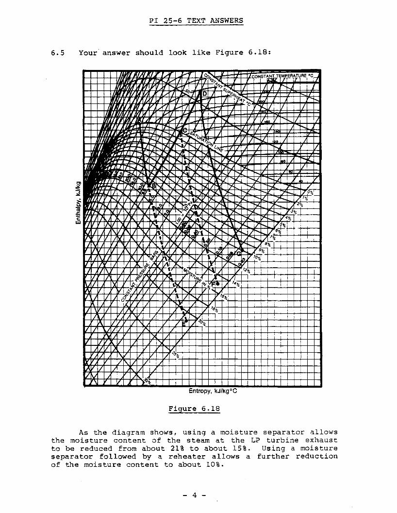
6.5 Your' answer should look like Figure 6.18:
~j'/~ ~ ~'~~~VKI/ 1/J~~~ ~~~7 • ~ ~J~J ~
.~ ~~ ~ ~ ~ ~ ~ ~ ~
I ...
t'\) V ') /1/ 1/11 V / "l V
)I/V ) v 'V'j 'W V V 1/ "S~%,--+--+-j'-+-+--+-~-+-+-+-I-+-+-+-+--1'-+-+-+-+-I
V" / 1/ ),JII1/1/ J 1\.1/ )
IV) J ~.;'+-+--1-+-+--+-~-+-+-+-I-+-+-+-~-+-+--+-l---+-+--l--I-l--.I'\ V )%'
Entropy, kJ/kgOC
Figure 6.18
As the diagram shows, using a moisture separator allowsthe moisture content of the steam at the LP turbine exhaustto be reduced from about 21% to about 15%. Using a moistureseparator followed by a reheater allows a further reductionof the moisture content to about 10%.
- 4 -
PI 25-6 TEXT ANSWERS
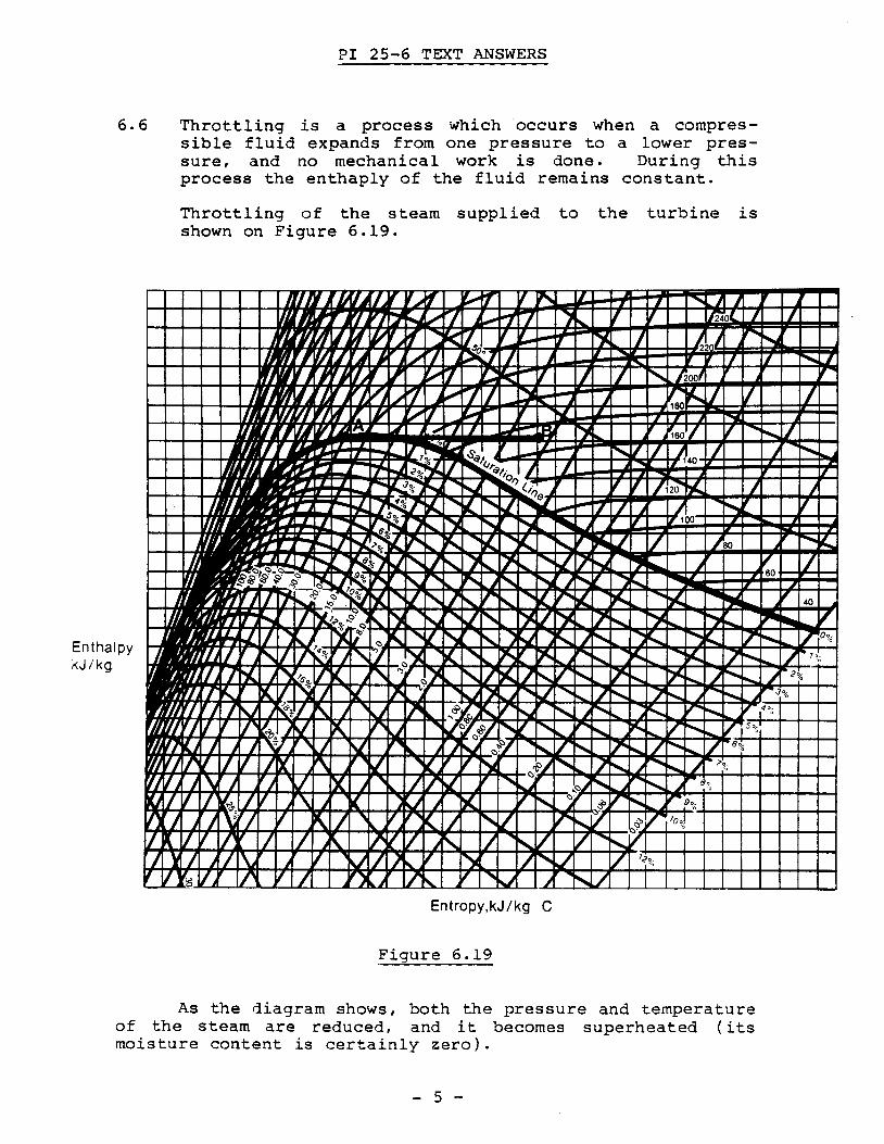
6.6 Throttling is a process which occurs when a compressible fluid expands from one pressure to a lower pressure, and no mechanical work is done. During thisprocess the enthaply of the fluid remains constant.
Throttling of the steam supplied to the turbine isshown on Figure 6.19.
EnthalpykJ/kg
Entropy,kJ/kg C
Figure 6.19
As the diagram shows, both the pressure and temperatureof the steam are reduced, and it becomes superheated (itsmoisture content is certainly zero).
- 5 -

PI 25-6 TEXT ANSWERS
6.7 Your answer should look like Figure 6.20
.117't--.. " ')l j r-...I 't-..)I I)<. i"'-. 1)1 ~ i Vo h( !JIl: r-... pe..... " I'-.. r-.... f"""l ,..,,1/
V / ,/ / ~ v///) V ,.( I Ij / '\ / / / <"S!!-~o+-11~--+--t-+-I-+--+-+-+-I-t--+--+-+!-+--+-+-f-t-l
r v /"-./ V /iA/l/ / /\./ V / / s 9-I-+--+-t-+-++-If-+-t-+-+-+--Hf-+-f-+-i-++-+-+-+-+-I'\ V )~-%-
Entropy, kJ/kg °C
Figure 6.20
As the diagram shows, throttling of the stearn suppliedto the turbine reduces the amount of heat which can be converted into mechanical work by the turbine (hA h B >he - hD)·
- 6 -