physics - university of british...
TRANSCRIPT

Physics
Circuit Problems
Science and Mathematics
Education Research Group
Supported by UBC Teaching and Learning Enhancement Fund 2012-2015
FACULTY OF EDUCATION FACULTY OF EDUCATION
Department of
Curr iculum and Pedagogy
F A C U L T Y O F E D U C A T I O N
Question Title Question Title Circuit Problems
Retrieved from: http://cdni.wired.co.uk/1920x1280/a_c/Circuit-board.jpg

Question Title Question Title Circuit Problems
The following questions have been
compiled from a collection of
questions submitted on PeerWise
(https://peerwise.cs.auckland.ac.nz/)
by teacher candidates as part of the
EDCP 357 physics methods courses
at UBC.

Question Title Question Title Circuit Problems I
Which direction do both the
conventional current and the
electrons in this circuit flow?
A. The current and the electrons both flow in the same direction, clockwise.
B. The current and the electrons both flow in the same direction,
counterclockwise.
C. The current and electrons flow in different directions. The current flows
clockwise while the electrons flow counterclockwise.
D. The current and electrons flow in different directions. The current flows
counterclockwise while the electrons flow clockwise.

Question Title Question Title Solution
Answer: D
Justification: A current is defined as the movement of an electric
charge. This charge does not have to be a positive or negative
charge. A flow of positive charges creates the same current as a
flow of negative charges moving in the opposite direction.
We now know that the charge carriers in an electric circuit are free
electrons, which move from the negatively charged terminal of the
power source towards the positively charged terminal (clockwise
in the diagram on the previous page).
However, when Benjamin Franklin was conducting experiments in
electricity, we did not know this fact about electric circuits. He
imagined positive charges were the carriers of electric current,
and defined electric current as flowing from a positive terminal to a
negative one (counterclockwise in the diagram).

Question Title Question Title Solution continued
Even though we now know that this is not the reality, to this day we still
define the conventional electric current direction as the direction in
which a positive charge would move. So even though the electrons are
flowing from negative to positive (clockwise in the diagram), we describe
current as flowing from positive to negative (counterclockwise in the
diagram).
Therefore the answer is D.

Question Title Question Title Circuit Problems II
In the diagram below, which meter is not connected correctly?
A. 1
B. 2
C. 3
D. 4

Question Title Question Title Solution
Answer: D
Justification: When using voltmeter and ammeters, ammeters always
need to be in series with the current they are measuring, and voltmeters
need to be in parallel.
This is because of the nature of series and parallel circuits.
In a parallel circuit, the potential difference is always the same, but the
current of the circuit is split between the multiple paths. Thus, if we were
to try to connect an ammeter in parallel, its presence would in fact
reduce the amount of current received by both it and the circuit it was
trying to measure.
In a series circuit, the current is always the same, but the potential
difference across components varies between the components in series.
Thus, if we were to connect a voltmeter in series, it would further split up
the potential difference it was trying to measure, and the reading would
be lower than the actual value in the circuit.

Question Title Question Title Solution continued
Looking at the previous diagram, meters 1 and 2 are ammeters, and 3
and 4 are voltmeters. We are looking for the meter that is NOT
connected correctly.
Meter 1 is in series with the circuit, so it is hooked up correctly. So A is
incorrect.
Meter 2 is in series with one of the parallel resistors, so it is also hooked
up correctly. So B is also incorrect.
Meter 3 is in parallel with the first parallel resistor branch, so it is hooked
up correctly. So C is incorrect.
Meter 4 is hooked up in series with the last resistor. Since meter 4 is a
voltmeter, this means it won't be able to accurately measure the
potential difference across the resistor, and is hooked up incorrectly. D
is the correct answer.

Question Title Question Title Circuit Problems III
Two resistors are wired in series. The second resistor has twice
the resistance as the first. Current passes through the
combination. Compared to the current through the first resistor,
the current through the second resistor is:
A. Twice the magnitude
B. The same
C. Half the magnitude
D. Quarter of the magnitude

Question Title Question Title Solution
Answer: B
Justification: Since the two resistors are in series, the current is the
same everywhere in the circuit.
Charge does NOT pile up and begin to accumulate at any given location
such that the current at one location is more than at other locations.
Charge does NOT become used up by resistors such that there is less
of it at one location compared to another. The charges can be thought of
as marching together through the wires of an electric circuit, everywhere
marching at the same rate. Current is the rate at which charge flows and
is the same everywhere in a series circuit.
Therefore, option B is the correct answer.

Question Title Question Title Circuit Problems IV
The diagram below shows combinations, X, Y and Z of three
identical resistors.
A. Y, X, Z
B. Z, X, Y
C. X, Y, Z
D. Z, Y, X
E. Y, Z, X
Combination X Combination Y Combination Z
What is the correct order of the total resistance of the combinations,
going from LOWEST resistance to HIGHEST resistance?

Question Title Question Title Solution
Answer: D
Justification: When resistors are in series, we simply add up the
resistances to get the total resistance.
When resistors are in parallel however, we add up the inverse of their
resistances, and then invert that sum. What this means is that in any
parallel circuit, the sum of the resistances will always be less than the
value of the smallest resistor.
So with combination X, we have one resistor in series with two parallel
resistors. The resistance of the parallel resistors will be half the
resistance of either one:
R
R
R
Question Title Question Title Solution continued
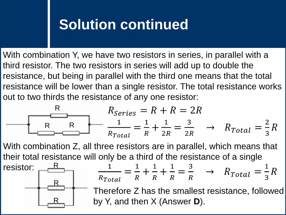
With combination Y, we have two resistors in series, in parallel with a
third resistor. The two resistors in series will add up to double the
resistance, but being in parallel with the third one means that the total
resistance will be lower than a single resistor. The total resistance works
out to two thirds the resistance of any one resistor:
R R
R
With combination Z, all three resistors are in parallel, which means that
their total resistance will only be a third of the resistance of a single
resistor:
R
R
R
Therefore Z has the smallest resistance, followed
by Y, and then X (Answer D).

Question Title Question Title Circuit Problems V
If we have a number of
identical 7 Ω resistors set up
as described in the diagram,
what is the total resistance
of that circuit, rounded to
the nearest ohm?
A. 14 Ω
B. 20 Ω
C. 28 Ω
D. 35 Ω

Question Title Question Title Solution
Answer: B
Justification: We know that resistors in series are described with the
relation:
Resistors in parallel are describe with the relation:
We know that we have R6 and R7 in series with a resistance of 14 Ω,
and we can think of the rest of the resistors as making up an equivalent
resistor that is in series with R6 and R7. So the total resistance would be
the resistance of this equivalent resistor added to the resistance of R6
and R7. Therefore the total resistance has to be more than 14 Ω.
Therefore answer A is incorrect.

Question Title Question Title Solution continued
If we look at the parallel branches which make up the equivalent resistor,
we can further eliminate answers. We know that R3 and R5 are similarly
in series with a resistance of 14 Ω. And we know that R1 and R2 are in
parallel, so their equivalent resistance has to be less than 7 Ω (because
for resistors in parallel, the equivalent resistance is always less than the
branch with the smallest resistance). In series with R1,2 is R4, so we know
the total resistance of R1,2,4 has to be less than 14 Ω, but more than 7 Ω.
Since we have two parallel branches (R3,5 and R1,2,4) that are
respectively 14 Ω and somewhere between 14 Ω and 7 Ω, the equivalent
resistance has to be below 14 Ω as well (the branch with the lowest
resistance). We have to add this to the series resistors R6 and R7, so we
have 14 Ω being added to something less than 14 Ω, so the total has to
be below 28 Ω.
Thus, Answers C and D cannot be correct because they are both above
28 Ω, leaving B as the correct answer.

Question Title Question Title Solution continued 2
If you want to see the detailed calculation explaining why the answer is
exactly 20 Ω, then read the section below.
To determine the total resistance of the circuit, we need to look at the
combination of the resistors in series and in parallel.
R1 and R2 are parallel resistors that act as
a single resistor in series with R4.
The resistance of this equivalent resistor
R1,2 is found with:

Question Title Question Title Solution continued 3
The equivalent resistor of R1, R2, and R4 has a
resistance of:
Resistors R3 and R5 are acting in series, so we add
their resistances up to find:

Question Title Question Title Solution continued 4
The equivalent resistor R3,5 is acting in parallel with
the equivalent resistor R1,2,4 and to find the
equivalent resistor R1,2,3,4,5 we use:

Question Title Question Title Solution continued 5
Now, we have this equivalent resistor acting
in series with R6 and R7 so all we need to do
is add up these resistances to find the total
resistance:
Therefore the answer is B
Question Title Question Title Circuit Problems VI
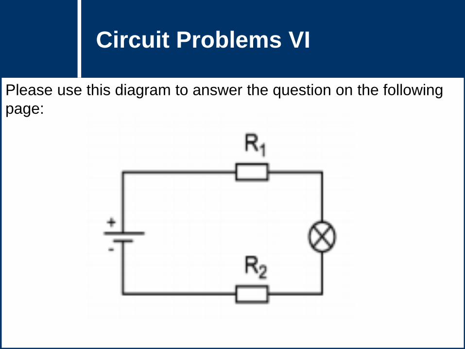
Please use this diagram to answer the question on the following
page:

Question Title Question Title Circuit Problems VI
continued
What will happen to the brightness of the bulb if the resistance of
R2 is increased and R1 remains constant?
A. The brightness of the lamp remains the same, because changing a resistor
only influences the brightness of the bulb if the bulb comes after the resistor.
B. The brightness of the lamp remains the same, because the battery is the
same and thus the same current is delivered.
C. The brightness of the lamp decreases, because the battery is the same and
thus the voltage is the same across the lightbulb.
D. The brightness of the bulb decreases, because the increased total
resistance lowers the current of the circuit.
E. The brightness of the bulb increases, because the increased total resistance
increases the current of the circuit.

Question Title Question Title Solution
Answer: D
Justification: The brightness of a bulb is dependent on the power the
bulb consumes.
Power is given by P = IV, where I is the current passing through the bulb
and V is the voltage drop over the bulb.
The current (I) drawn from a battery is dependent on the potential
difference (Vbattery) of the battery and the total resistance of the circuit.
The formula that relates these three variables is Vbattery = IRtotal.
Rtotal is calculated by adding up the resistances of each element in the
circuit.
In this case Rtotal = R1 + R2 + Rbulb
In this problem we are increasing R2 and thus increasing the total
resistance of the circuit.

Question Title Question Title Solution continued
From the equation Vbattery = IRtotal we can rearrange to see that
I = Vbattery /Rtotal. Since Vbattery is not changing (the battery remains the
same) and Rtotal has increased we know that I must decrease.
Looking back we have that the power consumed by the lightbulb is
given by P = IV. We now know how the current behaves, but how do we
determine what happens to V? (Remember that V in this case refers to
the voltage across the bulb, and not the total voltage of the circuit)
The voltage drop across the lightbulb is given by V = IRbulb where I is the
current passing through the bulb and Rbulb is the resistance of the bulb.
We are not changing the lightbulb so we know that its resistance
remains constant, however we do know that the current passing through
the bulb will decrease due to the increasing Rtotal. Since I is decreasing
and Rbulb is constant we know that V must also be decreasing.

Question Title Question Title Solution continued 2
Finally, what is happening to the power? Since P = IV and we know that
by increasing R2 we are decreasing the current running through the
lightbulb, and we are also decreasing the voltage drop across the
lightbulb, therefore the power must also be decreased. As a result of the
decreasing power consumption the bulb will be less bright.
It is important to note that it wouldn’t matter if R1 or R2 were increased
(before or after the bulb), since increasing the resistance of one resistor
in series will decrease the current of the whole circuit (because it
increases the total resistance). Therefore the answer is D.
Try it out in this circuit simulator to
see for yourself!

Question Title Question Title Circuit Problems VII
Please use this diagram to answer the question on the following
page:

Question Title Question Title Circuit Problems VII
continued
Which of the
following diagrams
contains a lightbulb
that will shine as
bright as the one on
the previous page?
Each lightbulb has
the same
resistance.
A. B.
C. D.

Question Title Question Title Solution
Answer: B
Justification: The brightness of a lightbulb depends on the power that
the lightbulb dissipates. This power is determined by the current that
passes through the lightbulb, by using the relationship P = I2R.
A) Two batteries connected backwards will produce no current, no
matter if you have 2 batteries in a circuit connected to the 2 lightbulbs.
B) Correct! Parallel batteries will produce the same voltage as the single
battery in the original diagram. The only difference is that the system will
run longer with twice as much energy.
C) The circuit has two lightbulbs in parallel connected with one lightbulb
in series. We can use the parallel/series equations for adding up
resistance to find out that the equivalent resistance of these lightbulbs is
1.5 times greater than the resistance of the original circuit. Since the
voltage is the same as in the original circuit, the total current of the circuit
will decrease (using the relation I = V/R). Therefore none of the lightbulbs
will shine equally as the one in the question.

Question Title Question Title Solution continued
D) The circuit has two lightbulbs in parallel connected with another two
lightbulbs in parallel. The equivalent resistance of this combination is the
same as one light bulb connected to the battery, so it is the same as the
resistance of the original circuit. Therefore, the same current will be
drawn from the battery initially. However, the current splits off as it
passes the first parallel junction, and therefore the current (and thus the
power) will be lower for each parallel branch. Thus the lightbulbs will
shine less brightly than the one in the question. The current meets but
splits up again in the next junction. Therefore, none of the lightbulbs will
shine as brightly as the one in the question.

Question Title Question Title Circuit Problems VIII
For the following circuit, if a resistor is added in parallel with R1,
what happens to the current delivered by the battery?
A. It will decrease.
B. It will stay the same.
C. It will increase.

Question Title Question Title Solution
Answer: C
Justification: If we add another resistor (let us call it R4) in parallel with
R1, there would be three resistors in parallel (R1, R2 and R4), and these
resistors would be in series with resistor R3. Adding another resistor will
decrease the equivalent resistance of the resistors in parallel and
eventually decrease the overall equivalent resistance of the circuit.
Since V = IR and V stays the same because we are using the same
battery, the current I will increase due to the decrease in R.

Question Title Question Title Circuit Problems IX
The circuit below consists of a battery, five identical resistors and
a switch.
A. R1 & R5
B. R2
C. R3 & R4
D. R3
E. R5
With the switch open, which resistor(s) has the least current
flowing through it?

Question Title Question Title Solution
Answer: C
Justification: As R1 and R5 are connected in series to the battery, the
full current of the circuit will flow through both, so neither answer A or E
can be correct.
R2 is in parallel with R3 & R4 (combined). It may look like only R3 is in
parallel to R2, as they are literally parallel in the diagram, but if you
follow the path of the current, it flows through R3 & R4 before returning
to a junction connecting it to R2. R3 & R4 are in series. Since the total
resistance of the R2 branch (1 resistor) is less than the total resistance
of the R3 & R4 branch (2 resistors in series), the R2 branch will have a
greater current flowing through it than the R3 & R4 branch, thus answer
B is incorrect.
As R3 & R4 are in series, they will have the same current flowing
through them. Thus the correct answer is C.
To further investigate these concepts, go to: and build a circuit.

Question Title Question Title Circuit Problems X
If the switch in the circuit below is closed, what happens to the
current passing through R3? Assume all resistors are identical
and that it is an ideal system.
A. It increases
B. It decreases
C. It stays the same
D. It becomes 0
E. Not enough information

Question Title Question Title Solution
Answer: D
Justification: The switch is in a parallel circuit loop to R3. Before the
switch is closed, the switch is in an open (incomplete) loop, and
therefore no current passes through it.
When the switch is closed, it creates a closed loop in the circuit with 0
resistance (ideal wire) that is parallel to R3. The current will all flow
through the switch, and none will flow through R3.

Question Title Question Title Solution continued
Remember that current flowing through parallel branches is inversely
proportional to the ratio of the branches’ resistances. Since the switch
has infinitely less resistance (0 ohms vs. >0 ohms), it will have infinitely
more current (>0 amps vs. 0 amps).
Therefore D is correct.
To further investigate these concepts, go to: and build a circuit.

Question Title Question Title Circuit Problems XI
If another identical resistor (R6) is added to the circuit, what
happens to the total resistance of the system when the switch is
closed? Assume all resistors are identical and that the system is
ideal.
A. It stays the same
B. It increases
C. It decreases
D. It decreases to 0
E. We need to know the resistance of R1 - R6

Question Title Question Title Solution
Answer: C
Justification: This problem can be solved conceptually using
knowledge of parallel and series circuits.
When the switch is closed, R6 becomes parallel to R3 (but not R4!).
The resistances of R3 and R6 can be added to find the total resistance
RT1 using:
Since we know that the total resistance of parallel resistors is less than
the smallest of the resistors, and since R3 and R6 are identical, we
know that RT1 is less than R3 or R6.

Question Title Question Title Solution continued
We can redraw the circuit as below.
This circuit is the same as the circuit before the switch was closed, with
RT1 replacing R3. We have essentially just adjusted the resistance of
one of the resistors in the circuit.
Since we know that RT1 < R3, we therefore know that the total
resistance of the new circuit is less than that of the old circuit.
Therefore C is the correct answer.
You can use the PhET Circuit Construction simulation:
to test such circuits out and see how adding/removing
resistors affects the overall resistance and the current.

Question Title Question Title Circuit Problems XII
In the circuit diagram R1, R2, R3 and R4 are all lightbulbs with a
resistance of 2 Ω. The battery has a voltage of 12 V. Use the
diagram to answer the following question.
A. R1
B. R2
C. R3
D. R4
E. All bulbs will have the same brightness because
they all have the same resistance.
Which bulb is the brightest?

Question Title Question Title Solution
Answer: A
Justification: To begin it can be useful to draw how the current gets
divided up in this circuit as shown below:
From this labelling we can make the following claims:
I1 = I2 + I3
I4 = I2 + I3
Therefore I1 = I4 (this is not needed for this question, but it is useful to
understand!).

Question Title Question Title Solution continued
Since I1 = I2 + I3 and we cannot have a negative current, this means that
I1 ≥ I2 and I1 ≥ I3. The brightness of a bulb is determined by the power
that the lightbulb dissipates, given by the formula P = I2R. Since all of
the lightbulbs have the same resistance, this means that the
determining factor for their power output is the current (I) passing
through them. Specifically, the bulb with the greatest amount of current
running through it will shine the brightest. Therefore, R1 shines the
brightest (since the current passing though R1 (I1) is greater than the
current passing through any of the other bulbs).
Another way to think about it is that R1 is brightest because all of the
current from the battery must go through R1. The current going through
the other bulbs is only a fraction of the current going through R1 and
since they all have the same resistance, this means R1 is the brightest.
Therefore the answer is A.

Question Title Question Title Circuit Problems XIII
In the circuit diagram R1, R2, R3 and R4 are all lightbulbs with a
resistance of 2 Ω. The battery has a voltage of 12 V. Use the
diagram to answer the following question.
What is the total effective
resistance of the circuit?

Question Title Question Title Solution
Answer: C
Justification: Here the first thing to notice is that R3 and R4 are
actually in series with one another. Therefore the effective resistance of
these two bulbs can simply be added. R2 and (R3 + R4) are in parallel,
which means that the effective resistance of these three bulbs R234 can
be found using:
This process above can be thought of as reducing the circuit to a
simpler and simpler circuit. This is shown schematically below:

Question Title Question Title Solution continued
Now it is as if there are two bulbs in this circuit R234 and R1 that are in
series with one another. Therefore the total resistance is:
This answer can be arrived at conceptually by analyzing the provided
answers to see which answers are actually possible:
A) 8 Ω – this is Rtotal when all bulbs are in series with one another, but
we know that in parallel we do not simply add the resistances together,
therefore this is incorrect.
B) 1 Ω – this cannot be the total resistance of the circuit because it is
less than the resistance of R1, and all the current must go through R1,
therefore the total resistance needs to be at least the value of R1.
Therefore this answer is incorrect.
(answer C)

Question Title Question Title Solution continued 2

Question Title Question Title Circuit Problems XIV
In the circuit diagram R1, R2, R3 and R4 are all lightbulbs with a
resistance of 2 Ω. The battery has a voltage of 12 V. Use the
diagram to answer the following question.
A. i & iii
B. iii only
C. i & v
D. ii & iii
E. i &iv
What will happen if R2 → 0 Ω
(i.e. the bulb is replaced with
a wire)?
i. R1 will get brighter
ii. R1 will get dimmer
iii. R3 and R4 will both get brighter
iv. R3 and R4 will both get dimmer
v. R3 and R4 will both go out

Question Title Question Title Solution
Answer: C
Justification: First of all, lets figure out what happens when R2 → 0 Ω.
When R2 → 0 Ω this means that there will be no resistance along the
path where R2 is, which means that instead of the current splitting into
the two different branches (R2 branch and R3+R4 branch), all of the
current will only along the R2 branch (of zero resistance). This means
that no current will pass through R3 and R4. This will decrease the
effective resistance of the whole circuit (since R1 is the only resistor with
current passing through it), and since the battery remains the same we
can use the relationship V = IR to see that the current produced by the
battery will increase. We know that an increase in current corresponds
to an increase in power, from the relation P = I2R. Therefore the power
output of R1 will increase, and since power output is directly related to
brightness, the brightness of R1 will increase.

Question Title Question Title Solution continued
i) R1 will get brighter – this is correct because more current flows
through R1
ii) R1 will get dimmer – this is incorrect because more current flowing
through R1 will make it brighter
iii) R3 and R4 will both get brighter – this is incorrect because no
current will be flowing through this part of the circuit
iv) R3 and R4 will both get dimmer – this is incorrect because no
current will be flowing through this part of the circuit
v) R3 and R4 will both go out – this is correct because no current will
be flowing through this part of the circuit
Therefore we can see that i and v are correct, therefore the correct
answer is C.

Question Title Question Title Circuit Problems XV
Two identical light bulbs are connected first in a series circuit and
then in a parallel circuit with the same battery.
In which circuit will the bulbs be brighter?
A. The bulbs will be brighter in the series circuit
B. The bulbs will be brighter in the parallel circuit
C. The bulbs will be equally bright in both circuits
D. There is not enough information provided to answer this question

Question Title Question Title Solution
Answer: B
Justification: If we simplify the circuit where the bulbs are in series we
see that the total resistance of the circuit is: Rtotal = 1R + 1R = 2R.
If we simplify the circuit where the bulbs are in parallel we see that the
total resistance of that circuit is:
The total resistance when the bulbs are in series is higher than the total
resistance when the bulbs are in parallel.
The power dissipated by a bulb is:
So, as the total resistance of a circuit is reduced its corresponding
power is increased. Therefore the circuit with the lowest total resistance
would have the most power – thus the parallel circuit will have more
power output, which means the bulbs will shine brighter.

Question Title Question Title Solution continued
Furthermore, if we look at the flow of current through the two systems
we see that it decreases in a circuit wired in series, whereas it is split
equally in the circuit wired in parallel (in this scenario, where the
resistances are the same). This is because in the relationship V = IR, if
R decreases then I must increase in order for voltage to stay constant
(the battery stays the same). When resistance is lower (in the parallel
circuit) the electrons flow more freely in the system.
We can put the power relationship in this way: P = IV
We can see here that if voltage is kept the same (the same battery),
then a decrease in current would decrease the power output of the
system. Therefore the series circuit (which has higher total resistance,
and therefore lower current) will have a lower power output, whereas the
parallel circuit (with lower total resistance and therefore higher current)
will have a higher power output (brighter bulbs).
Therefore the answer is B.

Question Title Question Title Circuit Problems XVI
Two identical light bulbs are connected first in a series circuit and
then in a parallel circuit with the same battery.
Which of the follow equations best describes the relative amount
of power dissipated in each circuit?
A. Pseries = Pparallel / 4
B. Pseries = Pparallel / 2
C. Pseries = Pparallel
D. Pseries = Pparallel × 2
E. Pseries = Pparallel × 4

Question Title Question Title Solution
Answer: A
Justification: If we simplify the circuit where the bulbs are in series we
see that the total resistance of the circuit is: Rtotal = 1R + 1R = 2R.
If we simplify the circuit where the bulbs are in parallel we see that the
total resistance of that circuit is:
The power dissipated by a bulb is:
Power for the circuit in series is:
Power for the circuit in parallel is:

Question Title Question Title Solution continued
The relationship between the power of the two circuits is:
Therefore: (answer A)

Question Title Question Title Circuit Problems XVII
Compare the current passing through R1 (5 ohms) to the current
passing through R2 (5 ohms) the moment after the switch is
closed.
A. I1>I2
B. I1=I2
C. I1<I2
D. No current will flow through the circuit.

Question Title Question Title Solution
Answer: B
Justification: The moment the switch is closed the potential difference
between the positive and negative ends of the batteries acts on the electrons
in the wires, causing them to move from the negative end to the positive end
of the battery.
By replacing the wires with pipes full of water, the battery with a pump and
the resistors with turbines you can make a hydraulics analogy. When the
switch is open the pump is off, and when the switch is closed the pump is on:
Pump off: Pump on:
Note: To view animation, enter ‘slide show’ mode
Question Title Question Title Solution continued
Water is an incompressible fluid, which means if you push water at one
end of a pipe the water throughout the remainder of the pipe has to
move to make room for it. By turning on the pump the water inside the
pump is propelled forward, which in turn pushes the water beyond that,
resulting in movement of the water throughout the pipes.
Electrons behave in the same way. There are electrons throughout the
wires before the switch is closed and since the electrons repel and are
also incompressible, when some electrons move all electrons move. So
when the switch is closed, current will immediately start flowing
throughout the whole circuit.
Therefore as soon as the current starts flowing through resistor R1, it
will also start flowing through resistor R2 (this is instantaneous).
Since this is a series circuit, the current will be the same throughout the
circuit, therefore I1 = I2 (answer B).

Question Title Question Title Solution continued 2
Extended explanation:
What if R1 and R2 had different resistances? Would these differences
affect the current passing through the resistors?
The current flowing depends on the voltage and the total resistance of
the circuit: V=IRtotal , therefore I=V/Rtotal
Therefore it doesn’t matter if R1 and R2 have the same or different
resistances, the current flowing through them will be the same (the
current is dependent on the combined total resistance of the two).
In the hydraulic analogy we can visualize this by imagining a series of
two turbines. If one turbine takes a huge amount of force to rotate and
the other takes a small amount, the water will move at a fixed rate
through both turbines. This is because the combined resistance sets the
possible flow of water, given a constant pumping power (voltage).
Thus the current passing through R1 and R2 will be the same.

Question Title Question Title Circuit Problems XVIII
How does the current through R1 compare with the current
through R2 immediately after the switch is first closed?
A. The current through R1 is greater than the current through R2.
B. The current through R2 is greater than the current through R1.
C. The current through R1 is equal to the current through R2.
D. The current flowing through both resistors will be zero.

Question Title Question Title Solution
Answer: A
Justification: Immediately after the switch is closed there is no charge
built up on the capacitor. An uncharged capacitor behaves like a short
circuit in the sense that there is no voltage drop over the capacitor and
thus current will flow with no resistance to charge the capacitor.
To create a hydraulic analogy to the situation imagine the same "circuit"
of water pipes with resistor replaces by narrow segments of pipe and
capacitors replaced with a stretchy water proof membrane.
Capacitor: Resistor:
Note: To view animation, enter ‘slide show’ mode

Question Title Question Title Solution continued
Immediately after the switch is closed we know water will flow through
the first resistor because it is the only path the water can take. After the
first resistor, the current has a choice between going through the second
resistor (narrow pipe) or proceeding towards the membrane.
From the water’s perspective the narrow pipe provides a resistance to
the flow of water, while the membrane/capacitor hasn't been
stretched/charged and thus provides no resistance to the water. Since
water (and electrons) prefer the path of least resistance, all of the
current will flow towards the capacitor and none will flow towards the
second resistor. Thus the current through R1 will initially be greater than
the current through R2.

Question Title Question Title Solution continued 2
From the analogy we can also see that the capacitor only has zero
resistance for the instant the switch is flipped. As water stretches the
rubber membrane the resistance to more water entering the pipe
increases and thus the moment after the instant the switch is closed
the resistance of the capacitor will be non-zero and thus some current
will pass through R2.
Returning to our electrical circuit we can now see that at the moment the
switch is closed the capacitor has near zero resistance and thus "shorts"
the second resistor.
This results in a current passing through R1 but no current passing
through R2 the instant the switch is closed (answer A).
Try it for yourself using the
following AC/DC circuit sim:

Question Title Question Title Circuit Problems XIX
A piece of Nichrome resistance wire of length L is connected up to
a battery and has a resistance of RL. This same wire is then
shaped into a circle and connected up to the same battery by
connecting two diametrically opposite points on the wire to the
circuit.
L
1 2

Question Title Question Title Circuit Problems XIX
continued
What is the equivalent resistance (RE) of the wire in the second
circuit?
A. RE is infinite (an open circuit)
B. RE = RL
C. RE = ½ RL
D. RE = ¼ RL
E. RE = 0 (a short circuit)

Question Title Question Title Solution
Answer: D
Justification: To answer this question we must know that the resistance
of a wire is proportional to its length (in this case the cross sectional area
of the wire is negligible compared to its length).
Since the same wire is used in both circuits, we know that the length of
the wire (L) stays the same. Therefore, in the second diagram the
circumference of the circle must be L.
Since the wires connected to the
circle are diametrically opposite, this
means that the circle is effectively
split into two equal lengths that are
half the circumference (½ L):
½ L
½ L

Question Title Question Title Solution
Since the length (L) of the wire is proportional to its resistance, then we
can say that each branch (half of the circle) with length ½ L should have
a resistance of ½ RL.
So now we effectively have two resistors of resistance ½ RL in parallel:
We can now use the formula for parallel
resistors to work out the equivalent
resistance:
½ RL
½ RL
Therefore: (answer D)