physics and engineering of the epr - for · pdf filephysics and engineering of the epr keith...
TRANSCRIPT

Physics and Engineering of the EPR
Keith ArdronUK Licensing Manager, AREVA NP UK
Presentation to IOP Nuclear Industry GroupBirchwood Park, Warrington UK, November 10 2010
IOP 10th November 2010 Slide 2
AREVA NP
EPRs in UK
EPR is Generation 3+ PWR design - evolutionary development of the most recent French and German PWRs (N4 and Konvoi designs)EDF and AREVA have jointly applied for UK Generic Design Assessment (GDA) of an EPR based on the design of the Flamanville 3 EPR being constructed in FranceEDF plans to construct 4 EPR units in the UK- total output 4x1650MW(e). First unit targeted for operation in 2018. First UK EPR will be twin unit plant at Hinkley Point in SomersetOther UK utilities also considering adopting EPRs

IOP 10th November 2010 Slide 3
AREVA NP
Milestones in EPR Development
1987: Framatome and Siemens begin development of advanced PWR for deployment in Europe post 2000. Aim is an evolutionary development of the most modern PWRs then operating.1993: EPR conceptual design submitted to French and German Safety Authorities. 2000: French Safety Authority issues Technical Guidelines defining safety requirements of EPR.2005: Construction of first EPR begins in Finland (Olkiluoto 3).2007: Construction of EPR begins in France (Flamanville 3) 2007: Construction begins of 2 EPR units in China (Taishan). EDF/Areva apply for GDA for the EPR in the UK.2008: French government announce decision to build second EPR (Penly 3)
IOP 10th November 2010 Slide 4
AREVA NP
EPR Design Features
Design combines optimum safety & environmental features of N4 and Konvoi PWR designs
• Improved independence and segregation between redundant trains of protection systems,
• Improved balance between the prevention and mitigation of accidents
• Increased conservatism in the design of physical barriers to radioactivity release
• High neutronic and thermal efficiency…• Double-wall containment based on French N4: achieves very low
leakage in accident conditions (including severe accidents)• Global “aircraft shell” protects reactor building and other safety
buildings against aircraft impact, explosion etc

IOP 10th November 2010 Slide 5
AREVA NP
Comparison between EPR and N4/Konvoi
EPR KONVOI N4 PLANTS
Overall
Net electrical output ≈ 1 660 MW 1 365 MW 1 475 MW
Reactor thermal power 4 500 MW 3 850 MW 4 250 MW
Efficiency ≈ 36% 35.40% 34.50%
Plant design life 60 years 40 years 40 years
Core Design
Number of fuel assemblies 241 193 205
Type 17 x 17 18 x 18 17 x 17
Active length 420 cm 390 cm 427 cm
Linear heat rate 166.7 W/cm 166.6 W/cm 179 W/cm
Enrichment (max) 5 % U 235 4 % U 235 4 % U 235
Batch discharge burn up 55 to 65 MWd/kg 50 MWd/kg 50 MWd/kg
Number and kind of control rods 89 "black” rods 61 "black” rods 65 "black” rods8 "grey” rods
In core instrumentation “Top mounted” “Top mounted” “Bottom mounted”
40 years3.6 E19 nvt
40 years1.10 E19 nvt
60 years1.2 E19 nvt.
Fluence (design target)
Reactor Pressure Vessel
IOP 10th November 2010 Slide 6
AREVA NP
Comparison between EPR and N4/Konvoi
2 trains(2 pumps 100% per train,
2 heat exchangers per train)
4 trains(2 pumps and 1 heat exchanger
per train,2 trains with emergency pump)
4 trains(1 pump per train,
1 heat exchanger per train)
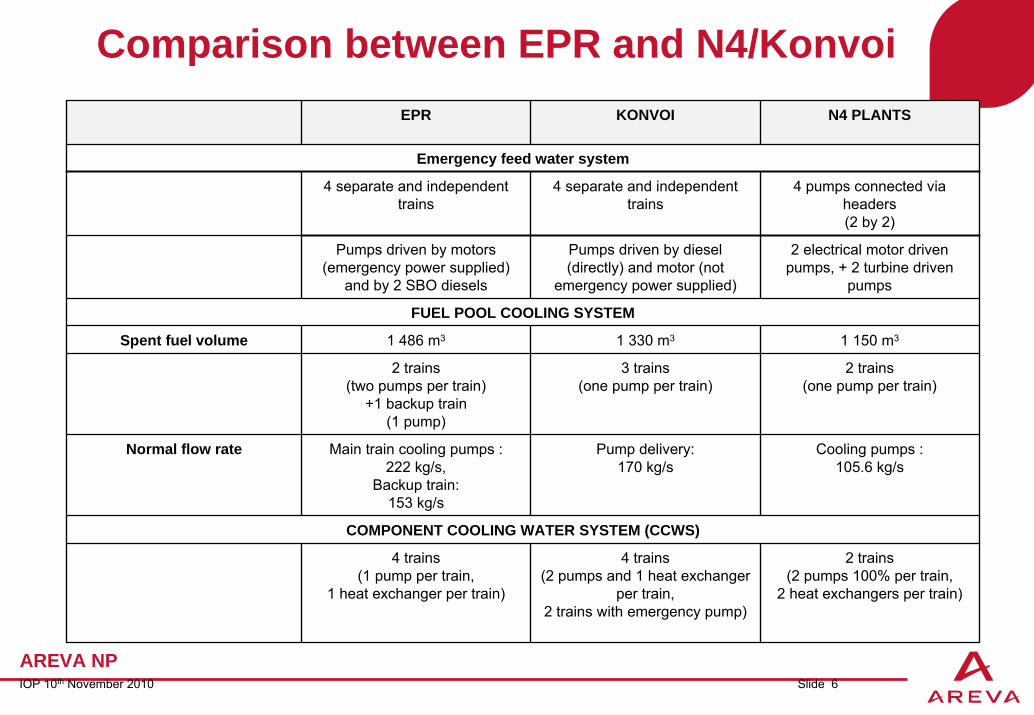
COMPONENT COOLING WATER SYSTEM (CCWS)
Cooling pumps :105.6 kg/s
Pump delivery:170 kg/s
Main train cooling pumps :222 kg/s,
Backup train:153 kg/s
Normal flow rate
2 trains(one pump per train)
3 trains(one pump per train)
2 trains(two pumps per train)
+1 backup train(1 pump)
1 150 m31 330 m31 486 m3Spent fuel volume
FUEL POOL COOLING SYSTEM
2 electrical motor driven pumps, + 2 turbine driven
pumps
Pumps driven by diesel (directly) and motor (not
emergency power supplied)
Pumps driven by motors (emergency power supplied)
and by 2 SBO diesels
4 pumps connected via headers(2 by 2)
4 separate and independent trains
4 separate and independent trains
Emergency feed water system
N4 PLANTSKONVOIEPR
IOP 10th November 2010 Slide 7
AREVA NP
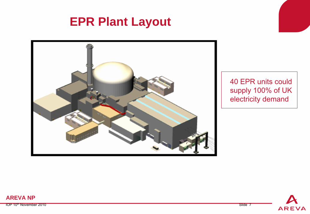
EPR Plant Layout
40 EPR units could supply 100% of UK electricity demand

IOP 10th November 2010 Slide 8
AREVA NP
Fuel AssembliesCharacteristics Data
Fuel Assemblies
•Fuel rod array 17 x 17
•Lattice pitch 12.6 mm
•Number of fuel rods per assembly 265
•Number of guide thimbles per assembly 24
Materials
•Mixing spacer grids
- Structure M5™
•Guide thimbles M5™
•Nozzles Stainless steel
•Hold-down springs Inconel 718
Fuel Rods
•Outside diameter 9.50 mm
•Active length 4200 mm
•Cladding thickness 0.57 mm
•Cladding material M5™
•Co-Mixed Burnable Poison (Typical)
•Material Gd2O3
•Gadolinium enrichment (wt%) 2 – 10

IOP 10th November 2010 Slide 9
AREVA NP
Safety and Environmental Performance

IOP 10th November 2010 Slide 10
AREVA NP
EPRTM Core CharacteristicsEPRTM
Large core of EPRTM is an evolution of earlier AREVA core designs
900 MWe, 157 fuel assemblies
1300 MWe, 193 fuel assemblies
1450 MWe, 205 fuel assemblies
EPRTM, 241 fuel assemblies
A B C D E F G H J K L M N P R S T
1716151413121110987654321
EPRTM main operating parametersThermal power : 4590 MWElectrical power : ~1600 MWeNumber of loops : 4Number of fuel assemblies : 241Fuel assembly array : 17x17Active fuel height in cm : 420

IOP 10th November 2010 Slide 11
AREVA NP
Fuel Cycle (1/2)Design reference fuel : UO2
Maximum fuel enrichment 5% w/o U235 Average discharge burnup consistent with U235 enrichment (55 to 65 GWd/mtU)Cycle lengths from 1 to 2 yearsMOX (UO2-PuO2) fuel loading capability (MOX not planned in UK currently)
Large core promotes flexible and economic fuel managementReduced radial leakage due to reduced Surface/Volume ratio
Heavy stainless steel reflector between the core and the core barrel (up to 30 cm thickness) improves neutron economy and further reduces neutron fluence to pressure vessel
IOP 10th November 2010 Slide 12
AREVA NP
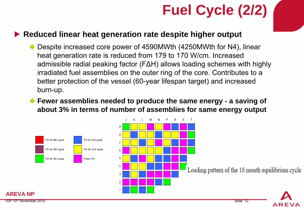
Fuel Cycle (2/2)Reduced linear heat generation rate despite higher output
Despite increased core power of 4590MWth (4250MWth for N4), linear heat generation rate is reduced from 179 to 170 W/cm. Increased admissible radial peaking factor (F∆H) allows loading schemes with highly irradiated fuel assemblies on the outer ring of the core. Contributes to a better protection of the vessel (60-year lifespan target) and increased burn-up.Fewer assemblies needed to produce the same energy - a saving of about 3% in terms of number of assemblies for same energy output

IOP 10th November 2010 Slide 13
AREVA NP
HEAVY REFLECTOR

IOP 10th November 2010 Slide 14
AREVA NP
IN-CORE INSTRUMENTATION – VIA UPPER HEAD ONLY
In-core instrumentation based on German design and experience
Aeroball • Reference instrumentation for power
distribution measurementSelf Powered Neutron Detectors (SPND)• Fixed incore instrumentation for online
core monitoring (surveillance and protection)
• Calibration based on Aeroball measurements
IOP 10th November 2010 Slide 15
AREVA NP
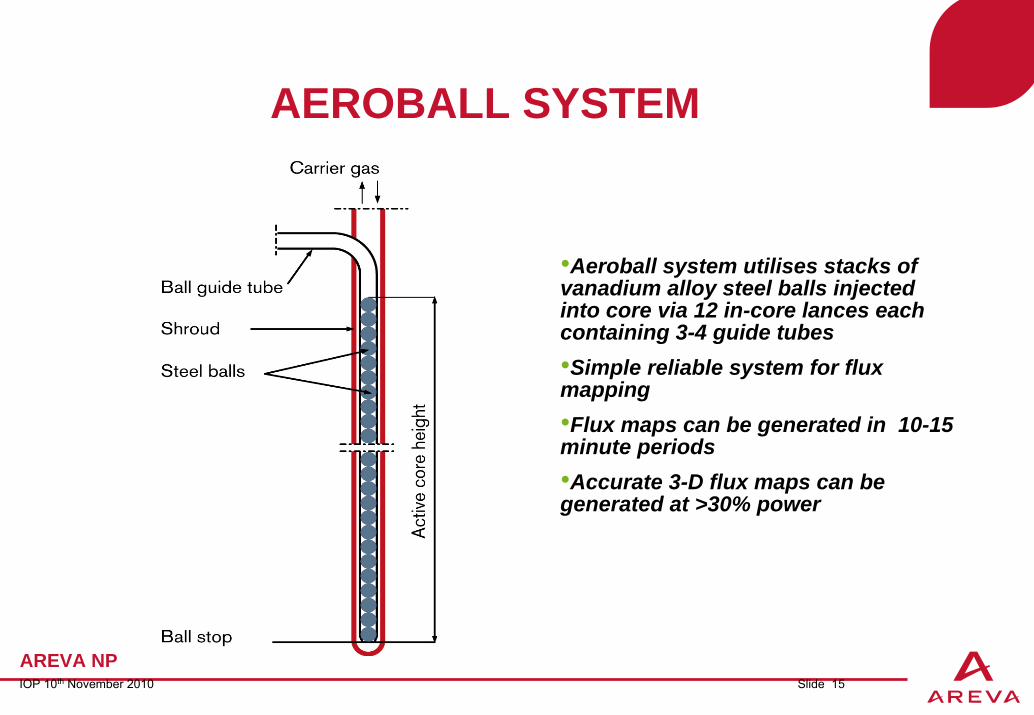
AEROBALL SYSTEM
•Aeroball system utilises stacks of vanadium alloy steel balls injected into core via 12 in-core lances each containing 3-4 guide tubes•Simple reliable system for flux mapping•Flux maps can be generated in 10-15 minute periods•Accurate 3-D flux maps can be generated at >30% power

IOP 10th November 2010 Slide 16
AREVA NP
REACTOR PRESSURE VESSEL
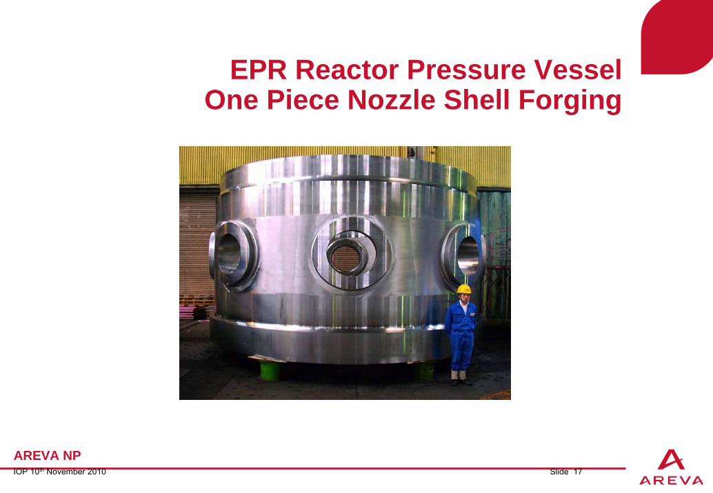
•Use of super-large forgings reduces number of welds •Nozzles are the “set-on” type requiring a less substantial weld bead.•No bottom head instrument penetrations to reduce risk from LOCAs due to penetration failure
IOP 10th November 2010 Slide 17
AREVA NP
EPR Reactor Pressure VesselOne Piece Nozzle Shell Forging

IOP 10th November 2010 Slide 18
AREVA NP
RCS LAYOUT/GEOMETRY – IMPROVED INHERENT SAFETY
•RPV, PZR, and SGs have increased volume-to-core power ratio reducing the magnitude of operational transients (e.g. peak overpressure in ATWT, MSIV closure)
•Core uncovery in SBLOCA avoided by:
•Increased volume of coolant between RPV nozzles and the top of the active core increased .•Reactor coolant pump inlet leg located above level of core top to avoiding core uncovery in “loop seal clearance” phase of SBLOCA
•Improved mitigation of accidents during shutdown conditions, particularly in mid-loop operation (e.g. extended time for operator action with loss of RHR).

IOP 10th November 2010 Slide 19
AREVA NP
Configuration of Safeguard Systems
All main safeguard systems and their associated electrical power supply and I&C systems are arranged in a four-train configuration:
• SIS/RHRS• EFWS• CCWS• ESWS
The four-train arrangement corresponds to the four-loop configuration of the RCS. Advantages:
• Simplified design concept - each system train associated with different RCS loop. • Flexible redundancy during plant shutdown conditions when capacity
requirements for heat removal and other functions are reduced • Ability to perform preventive maintenance of one complete safety train during
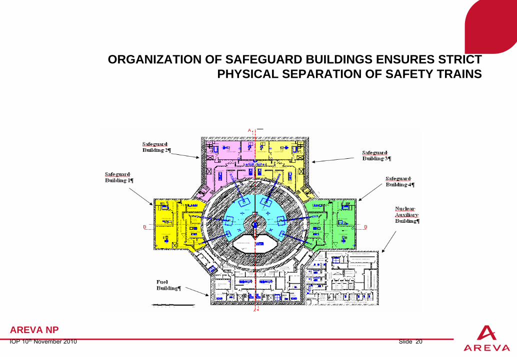
power operation.Safety trains located in geographically separated reinforced concrete buildings
Avoids common cause failure due to hazards – fire, aircraft impact etc
IOP 10th November 2010 Slide 20
AREVA NP
ORGANIZATION OF SAFEGUARD BUILDINGS ENSURES STRICT PHYSICAL SEPARATION OF SAFETY TRAINS
IOP 10th November 2010 Slide 21
AREVA NP
Reactor Building (Primary Containment) Structure
Reactor Building consists of a cylindrical outer reinforced concrete Shield Building, and inner pre-stressed concrete Containment Building with a 6 mm thick internal steel liner,Annular space between the Containment and Shield buildings maintained at sub-atmospheric pressure to collect and filter leakages from inner Containment Building.Low leakage to environment in design basis and severe accidents (core melt) Shield Building protects the Containment Building from aircraft impact, explosion pressure wave.

IOP 10th November 2010 Slide 22
AREVA NP
SHIELD BUILDING AND CONTAINMENT BUILDING INTERIOR STRUCTURES AND EQUIPMENT

IOP 10th November 2010 Slide 23
AREVA NP
AIRCRAFT IMPACT PROTECTIVE SHELL

IOP 10th November 2010 Slide 24
AREVA NP
Design against severe accidentsEPR design goal requires specific design provisions for severe accidents (core melt accidents). Philosophy of “Practical Elimination”of risk.Dedicated features included in design to address severe accidentchallenges:
• Dedicated valves for rapid depressurization of the RCS at high temperatures conditions to avoid high pressure core melt ejection (avoidance of Direct Containment Heating phenomena),
• Autocatalytic Hydrogen Recombiners to minimize the risk of hydrogen detonation,
• Containment designed to promote atmospheric mixing with the ability to withstand the loads produced by hydrogen deflagration,
• Provision of dedicated compartment to spread and cool molten core debris for long-term corium stabilization (core catcher),
• Provisions of CHRS with 2 trains allowing one train to be serviced or repaired if long term deployment necessary,
• Electrical and I&C systems dedicated and qualified to support severe accident mitigation features,

IOP 10th November 2010 Slide 25
AREVA NP
IRWST AND CORE MELT SPEADING AREA

IOP 10th November 2010 Slide 26
AREVA NP
CORE MELT SPREADING COMPARTMENT UNDER CONSTRUCTION AT OLKILUOTO 3

IOP 10th November 2010 Slide 27
AREVA NP
Flamanville 3 – UK EPR Prototype – July 2010

IOP 10th November 2010 Slide 28
AREVA NP
GDA – Status
Step 2 of GDA began August 2007. Concluded May 2008. 4 designs submitted.AECL and ESBWR designs later withdrawn, leaving only EPR and AP-1000 in the processGDA Step 3 began in June 2008. A Safety, Security and Environmental Report for the EPR was submitted for this step Step 4 GDA began in November 2009 - due to close June 2011.Residual issues remain to be closed out by NII. Not expected that GDA Certification of design will be achieved until mid-2012 (60 months since start of Step 2) EDF target to have first UK EPR at Hinkley Point unit operational in 2018

Questions…?