physical random access channel implementation on fpga
TRANSCRIPT
Physical Random Access ChannelImplementation on FPGA
Riku Ahonen
School of Electrical Engineering
Thesis submitted for examination for the degree of Master ofScience in Technology.Espoo 16.8.2021
Supervisor
Prof. Jussi Ryynänen
Advisors
M.Sc. Jorma Pallonen
M.Sc. Olli Piirainen

Copyright c⃝ 2021 Riku Ahonen

Aalto University, P.O. BOX 11000, 00076 AALTOwww.aalto.fi
Abstract of the master’s thesis
Author Riku AhonenTitle Physical Random Access Channel Implementation on FPGADegree programme Master’s Programme in Electronics and NanotechnologyMajor Micro- and Nanoelectronic Circuit Design Code of major ELEC3036Supervisor Prof. Jussi RyynänenAdvisors M.Sc. Jorma Pallonen, M.Sc. Olli PiirainenDate 16.8.2021 Number of pages 64 Language EnglishAbstractThe aim of this thesis is to design and implement physical random access channel(PRACH) for 5G on field-programmable gate array (FPGA). This implementation ispart of a larger radio research project with focus on beamforming. A key featurein the PRACH implementation of this thesis is support for grid-of-beams (GoB)beamforming. GoB is a type of beamforming which uses a static set of beams whichare used to cover all required beamforming directions.
This PRACH implementation should be compatible with Third Generation Part-nership Project’s (3GPP) 5G specification. The 5G specification allows for a lotof different PRACH configurations and the implementation should be configurableso that a large part of these can be supported. The FPGA resources which areconsumed by this PRACH implementation should be minimized because plenty ofother functionalities need to implemented on the same FPGA board as a part of thislarger project. Due to this the PRACH implementation needs to be resource efficientand small. Different PRACH configurations require varying amounts of processingpower and thus this implementation should also be scalable to allow minimizing theresource usage per required PRACH configurations in a certain use scenario.
To design the PRACH implementation for this thesis, existing PRACH designsare studied from the literature. It is found that typically PRACH implementationsfollow the same basic design. In this thesis this same basic design is followed buta notable deviation is the support for GoB beamforming. Matlab simulator wascreated and used to assess the planned design. The aim of the simulations was toverify that the design works acceptably but performance optimization was not in thescope of this thesis.
Next, the design was implemented in VHDL and verified against the Matlabsimulator to make sure it worked as expected. Xilinx Vivado tools were used to runsynthesis and implementation for the VHDL implementation. No issues were seen inthe Matlab simulator, VHDL simulation against Matlab, synthesis or implementation.In addition, utilization results from the implementation run were used to assessthat the design goals are met acceptably. Based on these results the PRACHimplementation was considered successful.Keywords 5G, PRACH, FPGA, VHDL, GoB, Beamforming

Aalto-yliopisto, PL 11000, 00076 AALTOwww.aalto.fi
Diplomityön tiivistelmä
Tekijä Riku AhonenTyön nimi Fyysisen hajasaantikanavan totetutus FPGA:llaKoulutusohjelma Elektroniikka ja nanoteknologiaPääaine Mikro- ja nanoelektroniikkasuunnittelu Pääaineen koodi ELEC3036Työn valvoja Prof. Jussi RyynänenTyön ohjaajat DI Jorma Pallonen, DI Olli PiirainenPäivämäärä 16.8.2021 Sivumäärä 64 Kieli EnglantiTiivistelmäTämän diplomityön päämääränä on suunnitella ja toteuttaa fyysinen hajasaantikana-va (PRACH) 5G:lle kenttäohjelmoitavalla porttimatriisilla (FPGA). Tämä toteutuson osa isompaa radiotutkimusprojektia, jonka pääpaino on keilanmuodostuksessa. Yk-si avainominaisuus tässä PRACH-implementaatiossa on tuki keilaristikko-tyyppiselle(GoB) keilanmuodostukselle. GoB-tyyppinen keilanmuodostus hyödyntää staattistakeilajoukkoa, jotka kattavat kaikki tarvittavat keilasuuntaukset.
PRACH-toteuksen tulee olla yhteensopiva Third Generation Partnership Pro-jectin (3GPP) 5G-spesifikaation kanssa. 5G-spesifikaatio sallii monien erilaistenkonfiguraatioiden käytön PRACH:ssa ja tämän toteutuksen tulee siitä syystä ollahyvin konfiguroitava, jotta iso osa näistä konfiguraatioista olisivat tuettuja. Tä-män PRACH-toteutuksen vaatimat FPGA-resurssit tulisi pitää minimissä, koskamonet muut tässä projektissa tarvitut toiminnallisuudet toteutetaan samalla FPGA-laitteella. Tämän takia PRACH-toteutuksen pitää käyttää resursseja tehokkaasti jaolla kaiken kaikkiaan pienikokoinen. Eri PRACH-konfiguraatiot vaativat eri määränprosessointivoimaa, joten tämän toteutuksen täytyy olla lisäksi skaalattava, jottaresurssienkäyttöä voidaan optimoida eri käyttötarkoituksiin tarvittujen konfiguraa-tioiden mukaan.
Tämän diplomityön PRACH-toteutuksen suunnittelua varten tehtiin kirjalli-suustutkimus aikaisemmista PRACH-toteutuksista. Tutkimuksessa huomattiin, ettätyypillisesti PRACH-toteukset noudattavat samanlaista peruskaavaa. Tässä diplomi-työssä PRACH suunniteltiin tämän peruskaavan mukaisesti, mutta huomattavanalisäyksenä oli tuki GoB-keilanmuodostukselle. PRACH-suunnitelman luomisessa javarmentamisessa käytettiin tämän diplomityön osana kehitettyä Matlab-simulaattoria.Simulaatioiden päämääränä oli varmentaa, että suunniteltu PRACH toimii hyväk-syttävällä tasolla. Syvällisempi suorituskykyoptimointi ei ole osa tätä diplomityötä.
Seuraavaksi suunnitelma toteutettiin VHDL:llä ja toteutusta verrattiin Matlab-simulaattoriin vastaavuuden varmentamiseksi. Xilinxin Vivado-työkaluja käytettiinsynteesin ja implementaation suorittamiseksi VHDL-totetukselle. Matlab-simulaattorissa,toteutuksen vertauksessa Matlab-simulaatioon, synteesissä tai implementaatiossa eihavaittu ongelmia. Lisäksi implementaation utilisaatiotuloksien perusteella arvioitiin,että toteutukselle määrätyt laadulliset tavoitteet saavutettiin hyväksyttävästi. Näidentulosten perusteella PRACH-toteutus todettiin onnistuneeksi.Avainsanat 5G, PRACH, FPGA, VHDL, GoB, Keilanmuodostus
5
PrefaceThe FPGA implementation of this thesis was done as a part of research radio projectin Nokia and the thesis was written for Master’s degree in Micro- and Nanoelectroniccircuit design major in Aalto University.
Writing this thesis took way too long and so I want thank my advisors JormaPallonen and Olli Piirainen from Nokia Bell Labs and supervisor Jussi Ryynänenfrom Aalto University especially for their patience in addition to the guidance duringthe thesis. This thesis topic was very interesting for me and it helped me learn a lotabout 5G layer 1 and especially PRACH. I want to thank all the people from bothMobile Networks and Bell Labs sides of Nokia who gave me the opportunity to workon such an excellent thesis topic. I also want to thank my brother for great help inpushing me to finish this thesis.
Espoo, 16.8.2021
Riku Ahonen
6
ContentsAbstract 3
Abstract (in Finnish) 4
Preface 5
Contents 6
Symbols and abbreviations 7
1 Introduction 10
2 Physical random access channel 132.1 Physical resources . . . . . . . . . . . . . . . . . . . . . . . . . . . . . 132.2 Preamble sequences . . . . . . . . . . . . . . . . . . . . . . . . . . . . 182.3 Preambles and mapping to physical resources . . . . . . . . . . . . . 222.4 Preamble detection . . . . . . . . . . . . . . . . . . . . . . . . . . . . 252.5 Beamforming . . . . . . . . . . . . . . . . . . . . . . . . . . . . . . . 27
3 Implementation 323.1 Project description . . . . . . . . . . . . . . . . . . . . . . . . . . . . 323.2 Xilinx UltraScale+ XCZU21DR . . . . . . . . . . . . . . . . . . . . . 343.3 Requirements . . . . . . . . . . . . . . . . . . . . . . . . . . . . . . . 383.4 State of the art . . . . . . . . . . . . . . . . . . . . . . . . . . . . . . 403.5 Resulting design . . . . . . . . . . . . . . . . . . . . . . . . . . . . . . 48
4 Results 524.1 Matlab simulation . . . . . . . . . . . . . . . . . . . . . . . . . . . . . 524.2 Logic simulation . . . . . . . . . . . . . . . . . . . . . . . . . . . . . . 544.3 Synthesis and implementation . . . . . . . . . . . . . . . . . . . . . . 54
5 Summary and conclusions 58
References 60

7
Symbols and abbreviations
Symbolsµ SCS configuration∆f SCS, ∆f = 2µ · 15 kHzTs Symbol timeLRA Preamble (sequence) lengthu Root sequence numberCv Cyclic shiftNCS Cyclic shift step size

8
Abbreviations3G Third generation3GPP Third Generation Partnership Project5G Fifth generationADC Analog-to-digital converterAPU Application processing unitAXI Advanced eXtensible interfaceAWGN Additive white Gaussian noiseBRAM Block RAMBTS Base transceiver stationCAZAC Constant amplitude zero autocorrelationC-RS Cell-specific reference signalCDF Cumulative distribution functionCLB Configurable logic blockCP Cyclic prefixCS Cyclic shiftCSI Channel state informationDAC Digital-to-analog converterDFT Discrete Fourier transformDFT-s-OFDM DFT-spread OFDMDSP Digital signal processingFDD Frequency division duplexingFDM Frequency-division multiplexingFFT Fast Fourier transformFIFO First-in-first-outFPGA Field-programmable gate arrayFR Frequency rangeGoB Grid of beamsIDFT Inverse DFTIFFT Inverse FFTIP Intellectual propertyITU International Telecommunication UnionMIMO Multiple-input and multiple-outputLTE Long term evolution

9
LUT Look-up tableOFDM Orthogonal frequency-division multiplexingOFDMA Orthogonal frequency-division multiple accessOSI Open systems interconnectionPAPR Peak-to-average power ratioPRACH Physical random access channelRA Random accessRACH Random access channelRAM Random access memoryRAR Random access responseRB Resource blockRF Radio frequencyRPU Real-time processing unitRTD Round-trip delayRTL Register-transfer levelSC-FDMA Single-carrier FDMASCS Subcarrier spacingSNR Signal-to-noise ratioSRS Sounding reference signalSSB Synchronization signal blockTA Timing advanceTDD Time division duplexingUE User equipmentVHDL VHSIC hardware description languageVHSIC Very high speed integrated circuit programWLAN Wireless local area networkZC Zadoff-ChuZCZ Zero-correlation zone
1 IntroductionSince the first generation of mobile communication networks in 1980s there has alwaysbeen an ever-increasing need for more network capacity and higher transfer rates.More network capacity and higher transfer rates are crucial as the amount of mobilenetwork users is always increasing and the usage pattern is moving towards mobilebroadband from only telephony services. International Telecommunication Union(ITU) predicts that global mobile network traffic will grow 10-100 times betweenyears 2020 and 2030. The main reasons behind this predicted growth are increasingvideo usage, number of network users, and downloading and updating of smart phoneapplications. [1]
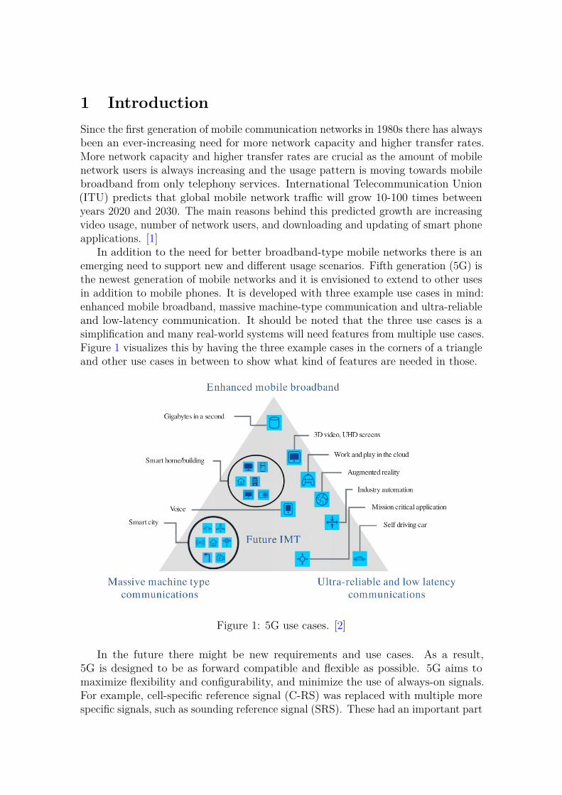
In addition to the need for better broadband-type mobile networks there is anemerging need to support new and different usage scenarios. Fifth generation (5G) isthe newest generation of mobile networks and it is envisioned to extend to other usesin addition to mobile phones. It is developed with three example use cases in mind:enhanced mobile broadband, massive machine-type communication and ultra-reliableand low-latency communication. It should be noted that the three use cases is asimplification and many real-world systems will need features from multiple use cases.Figure 1 visualizes this by having the three example cases in the corners of a triangleand other use cases in between to show what kind of features are needed in those.
Figure 1: 5G use cases. [2]
In the future there might be new requirements and use cases. As a result,5G is designed to be as forward compatible and flexible as possible. 5G aims tomaximize flexibility and configurability, and minimize the use of always-on signals.For example, cell-specific reference signal (C-RS) was replaced with multiple morespecific signals, such as sounding reference signal (SRS). These had an important part

11
in the 5G specification process. Another important topic in 5G is beamforming whichis becoming and integral part the Third Generation Partnership Project (3GPP)specifications with 5G after the first steps in the previous generation known asLong term evolution (LTE). Beamforming allows directing the transmissions andreceptions which results in more efficient use of the limited bandwidth and thusprovides improvements in network’s data rates.
An essential extension in 5G is exploitation of high-frequency bands. Thereare some unused spectra available in high.frequency bands which can provide extranetwork capacity when used in addition to the old low-frequency bands. In addition,there are wider bandwidths available which allows larger data transfer rates comparedto the narrower low-frequency bands. However, a disadvantage in high-frequencybands is shorter operating range. It is increasingly difficult to get power out of ahigh-frequency transmitter and, in addition, the signal attenuates faster. This meansthat 5G base transceiver stations (BTS) operating in high-frequency bands have tobe deployed more densely than BTSs in low-frequency bands.
Below the surface of the previous goals and features of 5G, the functions of thenetwork are divided into a set of channels. There are for examples own channelsfor user data and control data which is required to keep the user data flowing. Thechannels are also separated based on if they work in uplink or downlink direction.5G standards specify how all of these channels co-operate and how each of them isstructured. Another way to structure the things in 5G is to divide them per layer as isdone in the generic Open Systems Interconnection (OSI) model for communicationsnetworks. In OSI model all network functions are divided based on the level ofabstraction starting from the lowest level of hardware. In 5G there are layers 1, 2and 3. Higher layers from OSI model are beyond the scope of 5G. Layer 1 is thelowest of these and it implements the hardware-level functionality of 5G.
The aim of this thesis is to develop a physical random access channel (PRACH)implementation on Xilinx field-programmable gate array (FPGA) platform for usein an experimental 5G BTS. PRACH is one of the channels in the layer 1 of 5Gand its function is being the first message between user equipment (UE) and BTS.The PRACH implementation can be done in many different ways and one of themain things in this thesis is to study how the implementation could and should bedone. This study is mostly done as a literature study. Using the information fromthis study, a PRACH design is created with the help of Matlab simulations. Matlabsimulations are also used to check that the requirements given for the design arefulfilled. The design is then implemented in VHSIC hardware description language(VHDL) and finally the implementation is verified and tested with simulations.
When an UE is not connected to a cell and it wants to initialize a connection ithas to go through a procedure known as initial access. Initial access procedure canbe split into two parts: The first part for UE is finding an available cell in the area.BTS has to broadcast information about its existence so that an UE can find it. Thesecond part is initializing a connection with the found cell. UE checks for availablecells by scanning certain frequencies for an always-on broadcast signal that the BTSis sending periodically. This signal carries a synchronisation signal block (SSB) whichcontains information about the cell. The information from SSB is needed in the

12
second part of initial access.The second part of initial access is known as random access (RA) and its steps
are shown in Figure 2. These steps can be elaborated as follows:1. UE transmits a preamble to the BTS that sent the SSB. PRACH consists of
the transmission of this signal and its reception in the BTS.
2. The BTS replies with random access response (RAR) which informs the UEthat the preamble was received correctly. RAR also instructs the UE whichtime-alignment should be used in the following transmissions.
3. A pair of messages is exchanged between the UE and the BTS. These twomessages are called Message 3 and Message 4. Their function is to resolvepotential collisions if multiple UEs have sent the same preamble at the sametime.
Figure 2: RA process between UE and BTS. [3]
The function of PRACH is transmission and reception of a preamble from UEto BTS so that a connection can be initiated between them. PRACH being thefirst message means that the BTS has no knowledge if any UE is trying to senda preamble. The information available on UE’s side is also limited and all of itis gathered from the broadcast messages. BTS has certain reception windows forPRACH preambles and the UE tries to send its preamble so that is would hit thiswindow. The challenge in this is that neither device knows what is the distance andthus the delay that preamble transmission over the air will take. The UE has to sendthe preamble based on the timing it received the broadcast message. The BTS triesto detect preambles similarly during all of the certain PRACH reception windows.
This thesis starts with standard and theoretical background in Chapter 2 forthe physical resources in 5G, PRACH, how PRACH fits into the physical resourcesand beamforming. Next, Chapter 3 focuses on topics specific to the implementationin this thesis. The context and requirements of the implementation are discussedfirst before a literature study on earlier PRACH implementations, designs andbeamforming systems. Next, the design for this PRACH implementation is presentedand the choices made during the design are justified. Verification and results for theimplementation are discussed in Chapter 4.

13
2 Physical random access channelThis chapter describes PRACH from preamble generation in UE to detection inBTS. Section 2.1 will introduce the physical resources which are available to physicalchannels in NR. Explanation of PRACH starts in Section 2.2 with a description ofpreamble sequences in 5G. Section 2.3 shows how preamble sequences are used to formpreambles and how the preambles are mapped into the physical resources, describedin Section 2.1, for transmission. Section 2.4 discusses the detection of transmittedpreambles in BTS and presents the structure of a typical system for achieving that.Finally, Section 2.5 introduces the basics of beamforming and discusses what effectthe use of beamforming has on PRACH.
2.1 Physical resourcesThis section presents the structure of physical resources in 5G. First, orthogonalfrequency-division multiplexing (OFDM) is discussed as it is the basis of waveformin 5G both in uplink and downlink directions. The structure and basic units of thephysical resources are a consequence of the use of OFDM and thus are presentedafter OFDM. Finally, scheduling is discussed shortly as it controls how the physicalresources are appointed to different physical channels.
OFDM is a transmission scheme that allows transmitting data over multiplenarrowband carriers. Digital OFDM is realized with inverse discrete Fourier transform(IDFT) such that an input data stream modulates "frequency-domain amplitudes" ofIDFT input. The output from IDFT is then a single signal that consists of subcarriersmodulated by the input data streams. Similarly, an OFDM signal can be receivedby using discrete Fourier transform (DFT). The received signal is the "time-domain"input to DFT which outputs the original "frequency-domain amplitudes". [4]
Digital OFDM was popularized by the advances in digital integrated circuittechnology as the implementation of fast Fourier transform (FFT) became cheaperand more efficient. The advantages of OFDM are robustness to time dispersion andsimple structuring of time and frequency resources [3]. Unsurprisingly, there arealso disadvantages in OFDM and two main ones of these are high peak-to-averagepower ratio (PAPR) and sensitivity to frequency offset. High PAPR means that morepower backoff is needed in an amplifier to keep it from reaching saturation region dueto variance in input signal power. Today, digital OFDM is a popular transmissionscheme and it is used, for example, in wireless local area network (WLAN) in additionto 5G and LTE. [4]
An important part of OFDM is spacing the subcarriers in frequency such that theyare orthogonal. This will minimize the interference between subcarriers. Orthogonal-ity between the subcarriers requires that the subcarrier spacing (SCS) is reciprocalof symbol time. In 5G the smallest possible SCS is used and as a result the SCS willbe the inverse of symbol time: ∆f = 1/Ts. OFDM uses frequency resources moreefficiently than many other frequency-division multiplexing (FDM) schemes becausein OFDM the subcarriers are packed tighter such that they overlap each other. Withthe correct SCS all other subcarriers are zero at the center frequency of a subcarrier

14
which means that the subcarriers are indeed orthogonal. Figure 3 visualizes howsubcarriers overlap and become zero at the center frequencies. Orthogonality betweenthe subcarriers allows reception without separate band-pass filtering for each of thesubcarriers. This simplifies a receiver implementation compared to non-orthogonalFDM schemes. [4]
Figure 3: Overlapping orthogonal OFDM subcarriers. [4]
While the orthogonality of subcarriers provides many benefits in OFDM itcauses sensitivity to frequency offset. Frequency offset between the transmitterand the receiver cause the subcarriers to lose their orthogonality and thus addsinterference between the subcarriers. Frequency offset is caused by non-ideal frequencysynchronization between the transmitter and the receiver, and by Doppler shift if,for example, an UE is moving. [4]
Robustness against time dispersion is achieved in OFDM by the use of cyclicprefixes (CP). CP is a copy of the signals tail that is inserted before the signal.CP provides a guard period against multipath echoes of the signal and other timedispersion. Before demodulating the data the CPs and thus the interference in themare removed. The addition of CPs decreases the efficiency of OFDM and thus thereis a trade-off between less interference and efficiency. Length of the CP can be variedto match time dispersion at certain time and place. An empty guard period wouldprovide the same robustness against time dispersion as a CP. However, adding aCP makes the signal cyclic which makes channel response calculations much moreefficient to implement with digital circuitry. [4]
Sizes of SCS and CP are an important pair of parameters. Larger SCS reducesthe effect of phase noise and frequency offset. On the other hand, larger SCS resultsin shorter signals and thus CPs occur more often. When CPs occur more often theyshould be shortened to undo the decrease in efficiency but this can cause troublewith time dispersion. For these reasons the selection of SCS and CP length are verydetermining for the success of OFDM in a certain radio environment. [3]
Orthogonal frequency-division multiple access (OFDMA) is an FDM variant ofOFDM. Users are multiplexed in frequency by mapping data streams from multiple
15
users to different inputs of IDFT [4]. Naturally, demapping has to be done in thereceiver to extract the data streams for different users. 3GPP standards, e.g. [5], usethe word OFDM when referring to the used transmission scheme even though FDMis used and thus OFDMA would be a more descriptive name. However, if the wholebandwidth is given to a single user OFDM is an appropriate name for the scheme.In this thesis OFDM is used to refer to both single-user and FDM versions of OFDMas it is done in the 3GPP standards.
OFDM is used in 5G for both uplink and downlink transmissions. High PAPRof OFDM is especially a problem in uplink direction because transmissions fromUEs are limited by power and high PAPR makes realizing a high-efficiency poweramplifier more difficult. However, in 5G there is an option to use single-carrier FDMA(SC-FDMA) in uplink direction to lower PAPR and thus increase available transmitpower in an UE. SC-FDMA is a transmission scheme that is very similar to OFDM.The difference is that before the usual IDFT in OFDM transmitter a DFT is added.Similarly, IDFT is added after DFT in the receiver. Because only these DFT andIDFT blocks are added compared to OFDM SC-FDMA is also known as DFT-spreadOFDM (DFT-s-OFDM), that is OFDM with DFT precoding. In the usual OFDMdata stream symbols are transmitted in parallel on the subcarriers but in SC-FDMAthey are transmitted sequentially. This causes the lowered PAPR. SC-FDMA is notused in all situations because it also has some disadvantages compared to OFDM.Examples of these disadvantages are more complex spatial multiplexing and loss ofsymmetry between uplink and downlink. [3], [6]
OFDM allows natural and easy organization of time and frequency resources. In5G, resources are organized in a plane with frequency and time axes. Subcarrieris the basic unit in frequency axis and in time axis it is symbol. The amount ofsubcarriers in a carrier can be calculated by dividing the carrier’s bandwidth withSCS: nsc = BW/∆f . A single subcarrier and symbol together form a resourceelement which is the smallest physical resource in 5G. In frequency domain, 12consecutive subcarriers form a resource block (RB) which corresponds to a varyingbandwidth based on SCS. One thing to note is that a RB only measures frequency,not both frequency and time as it did in LTE. [3]
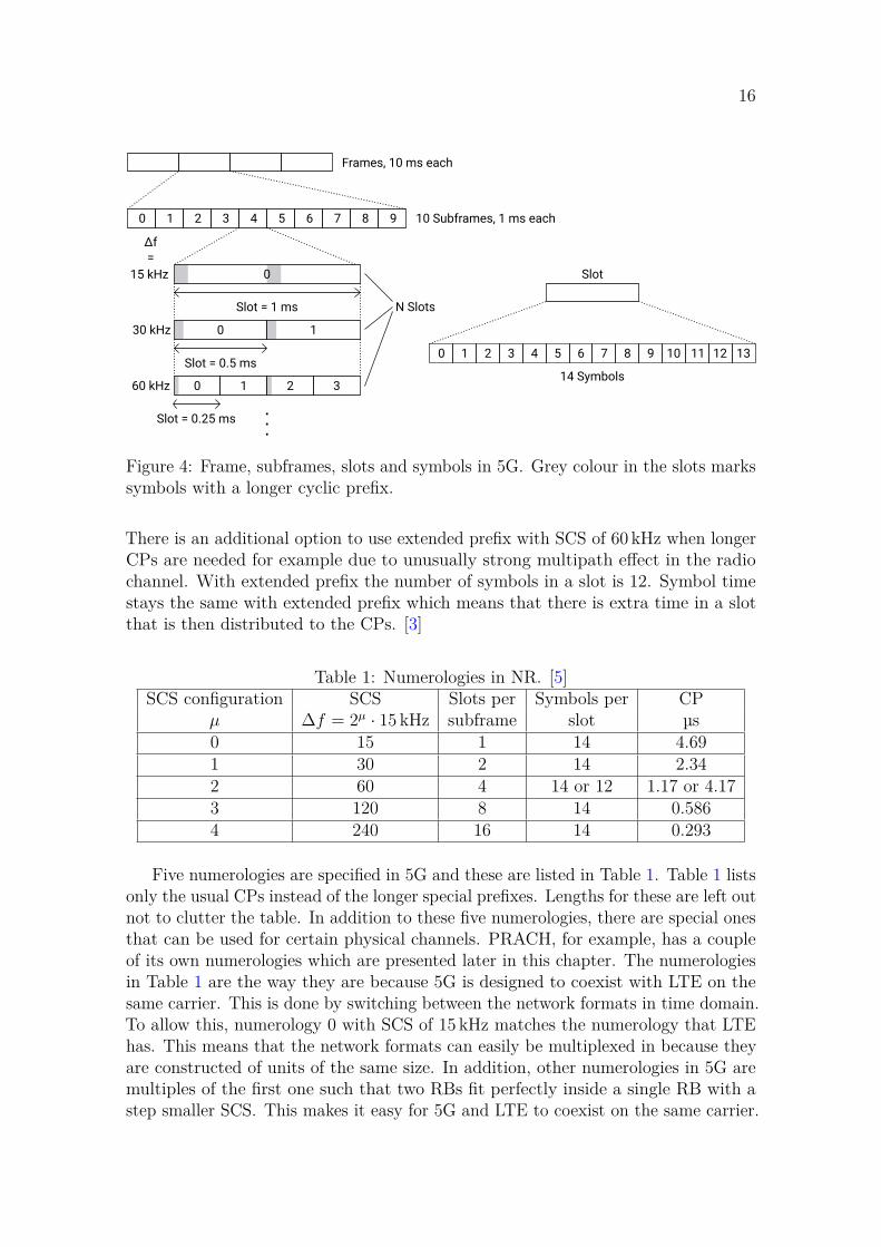
Time domain traffic in 5G is organized into frames that are 10 ms long. Eachframe is divided into 10 subframes each of which have an equal length of 1 ms. Thereis a varying amount of slots in a subframe. The number of slots per subframedepends on numerology which is a cell configuration option that selects the scale ofthe structure. The most deciding setting in a numerology is the SCS. Numerology0 has SCS of 15 kHz and a single slot per subframe. Increasing the SCS increasesthe amount of slots in subframe such that doubled SCS leads to twice as manyslots. Independently from the numerology, each slot contains 14 symbols that have aduration of 1/∆f . These configuration options are listed in Table 1. [5]
A CP is inserted before every symbol to provide robustness against time dispersionas was explained earlier in OFDM part of this section. All CPs have the same lengthexcept two special ones per subframe. The special CPs are before the first andcentermost symbols of the subframe. In Figure 4 grey colour in slots is used to markthe symbols with special CP. The special CPs are a bit longer than the normal ones.
16
0 1 2 3 4 5 6 7 8 9
15 kHz
30 kHz
60 kHz
Slot = 1 ms
Slot = 0.5 ms
Slot = 0.25 ms
Slot
0 1 2 3 4 5 6 7 8 9 10 11 12 13
Frames, 10 ms each
10 Subframes, 1 ms each
N Slots
14 Symbols
. . .
0
0
0
1
1 2 3
∆f
=
Figure 4: Frame, subframes, slots and symbols in 5G. Grey colour in the slots markssymbols with a longer cyclic prefix.
There is an additional option to use extended prefix with SCS of 60 kHz when longerCPs are needed for example due to unusually strong multipath effect in the radiochannel. With extended prefix the number of symbols in a slot is 12. Symbol timestays the same with extended prefix which means that there is extra time in a slotthat is then distributed to the CPs. [3]
Table 1: Numerologies in NR. [5]SCS configuration SCS Slots per Symbols per CP
µ ∆f = 2µ · 15 kHz subframe slot µs0 15 1 14 4.691 30 2 14 2.342 60 4 14 or 12 1.17 or 4.173 120 8 14 0.5864 240 16 14 0.293
Five numerologies are specified in 5G and these are listed in Table 1. Table 1 listsonly the usual CPs instead of the longer special prefixes. Lengths for these are left outnot to clutter the table. In addition to these five numerologies, there are special onesthat can be used for certain physical channels. PRACH, for example, has a coupleof its own numerologies which are presented later in this chapter. The numerologiesin Table 1 are the way they are because 5G is designed to coexist with LTE on thesame carrier. This is done by switching between the network formats in time domain.To allow this, numerology 0 with SCS of 15 kHz matches the numerology that LTEhas. This means that the network formats can easily be multiplexed in because theyare constructed of units of the same size. In addition, other numerologies in 5G aremultiples of the first one such that two RBs fit perfectly inside a single RB with astep smaller SCS. This makes it easy for 5G and LTE to coexist on the same carrier.
17
[3]Numerologies in 5G are designed with varying cell sizes and use cases in mind.
Smaller SCSs are used with longer CPs in traditional type of deployments as LTEwould be used. Larger SCSs are used with shorter CPs for operation in cells withhigher carrier frequencies. Cell size is limited by carrier frequency as higher frequenciesexperience a lot more attenuation per distance and thus these cells will be smaller.Time dispersion is usually less of in issue in smaller cells and for this reason CPscan be shorter with larger SCS. 5G specifies two frequency ranges (FR): FR1 forfrequencies below 6 GHz and FR2 for frequencies from 24.25 GHz to 52.6 GHz. Theseare used in parts of the 3GPP standards to restrict certain settings only for higheror lower carrier frequencies. [3]
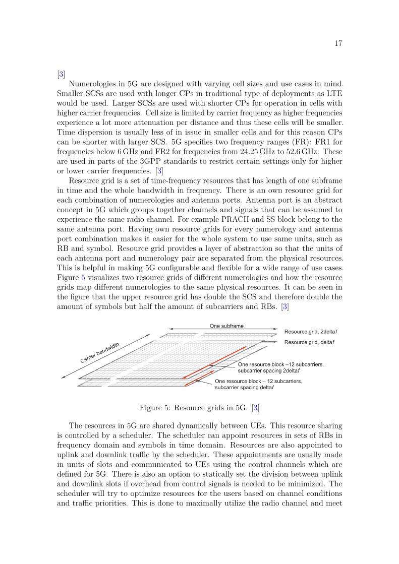
Resource grid is a set of time-frequency resources that has length of one subframein time and the whole bandwidth in frequency. There is an own resource grid foreach combination of numerologies and antenna ports. Antenna port is an abstractconcept in 5G which groups together channels and signals that can be assumed toexperience the same radio channel. For example PRACH and SS block belong to thesame antenna port. Having own resource grids for every numerology and antennaport combination makes it easier for the whole system to use same units, such asRB and symbol. Resource grid provides a layer of abstraction so that the units ofeach antenna port and numerology pair are separated from the physical resources.This is helpful in making 5G configurable and flexible for a wide range of use cases.Figure 5 visualizes two resource grids of different numerologies and how the resourcegrids map different numerologies to the same physical resources. It can be seen inthe figure that the upper resource grid has double the SCS and therefore double theamount of symbols but half the amount of subcarriers and RBs. [3]
Figure 5: Resource grids in 5G. [3]
The resources in 5G are shared dynamically between UEs. This resource sharingis controlled by a scheduler. The scheduler can appoint resources in sets of RBs infrequency domain and symbols in time domain. Resources are also appointed touplink and downlink traffic by the scheduler. These appointments are usually madein units of slots and communicated to UEs using the control channels which aredefined for 5G. There is also an option to statically set the division between uplinkand downlink slots if overhead from control signals is needed to be minimized. Thescheduler will try to optimize resources for the users based on channel conditionsand traffic priorities. This is done to maximally utilize the radio channel and meet

18
latency requirements of different traffic types. In case there is an event which needsimmediate response the scheduler can also preempt ongoing traffic and appoint thefreed resource to another UE even mid-slot. This will cause an error in the preemptedUE reception but there are multiple ways in 5G to handle this sort of errors and thuspreemption does not cause too much difficulties. These ways to handle preemptionsare out of scope of this thesis. [3]
2.2 Preamble sequencesThis section begins by presenting Zadoff-Chu (ZC) sequences which are used togenerate PRACH preamble sequences in 5G. The reasons for adoption of ZCsequences are discussed next. Then, the next topic is how ZC sequences are used togenerate the preamble sequences and what kind of differences there can be in thepreamble sequences for different use cases and configurations. The effect of thesedifferences to cell size are discussed in the end.
PRACH preamble sequences in 5G are ZC sequences. Preamble sequences arethen used to generate the actual preambles. Generation of actual preambles inpresented in Section 2.3. In 3GPP standard [5] a ZC sequence is described with thefollowing formula
xu(i) = e−jπui(i+1)
LRA , (1)where u is a root sequence number, LRA is the sequence’s length and i = 0, 1, ..., LRA−1. Different preamble sequences are generated by varying the sequence number. Inaddition to the sequence number, cyclic shift (CS) is used to generate more preamblesequences. CS is a time shift with the exception that sequence’s values which areshifted out of the sequence are put back into the sequence’s other, now empty, end.In the same 3GPP standard [5] CS is applied to Equation 1 is described with
xu,v(i) = xu((i + Cv) mod LRA), (2)
where Cv is a cyclic shift. These two equations are the basis of PRACH preamblesequences.
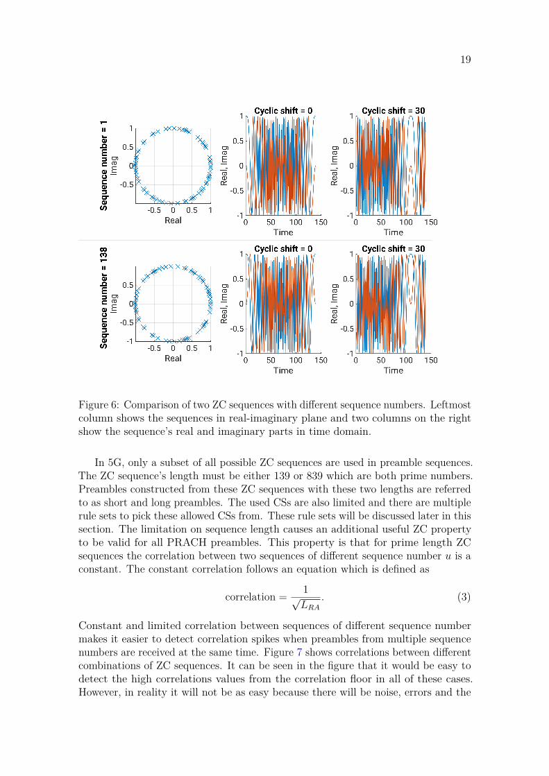
ZC sequences are constant amplitude zero autocorrelation (CAZAC) waveformswhich have two useful properties for use in communications systems as preambles.As the abbreviation CAZAC tells these two useful properties are constant amplitudeand zero autocorrelation. Constant amplitude naturally results in lower PAPRwhich improves a power amplifier’s efficiency. Zero autocorrelation means that thesequence’s autocorrelation is a delta function. What this means is that correlationwith any CS other than zero is zero and thus CSs of a ZC sequence are all orthogonalwith each other. Figure 6 shows a comparison of two ZC sequences with differentsequence numbers u and visualizes these two useful properties of CAZAC waveforms.The leftmost column shows how all unscaled sequence values are on a unit circle andthus the unscaled amplitude is constant one. The next two columns demonstratethe effect from CS. By comparing the two rows it can be seen how changing thesequence number generates a different sequence. [7]
19
Figure 6: Comparison of two ZC sequences with different sequence numbers. Leftmostcolumn shows the sequences in real-imaginary plane and two columns on the rightshow the sequence’s real and imaginary parts in time domain.
In 5G, only a subset of all possible ZC sequences are used in preamble sequences.The ZC sequence’s length must be either 139 or 839 which are both prime numbers.Preambles constructed from these ZC sequences with these two lengths are referredto as short and long preambles. The used CSs are also limited and there are multiplerule sets to pick these allowed CSs from. These rule sets will be discussed later in thissection. The limitation on sequence length causes an additional useful ZC propertyto be valid for all PRACH preambles. This property is that for prime length ZCsequences the correlation between two sequences of different sequence number u is aconstant. The constant correlation follows an equation which is defined as
correlation = 1√LRA
. (3)
Constant and limited correlation between sequences of different sequence numbermakes it easier to detect correlation spikes when preambles from multiple sequencenumbers are received at the same time. Figure 7 shows correlations between differentcombinations of ZC sequences. It can be seen in the figure that it would be easy todetect the high correlations values from the correlation floor in all of these cases.However, in reality it will not be as easy because there will be noise, errors and the
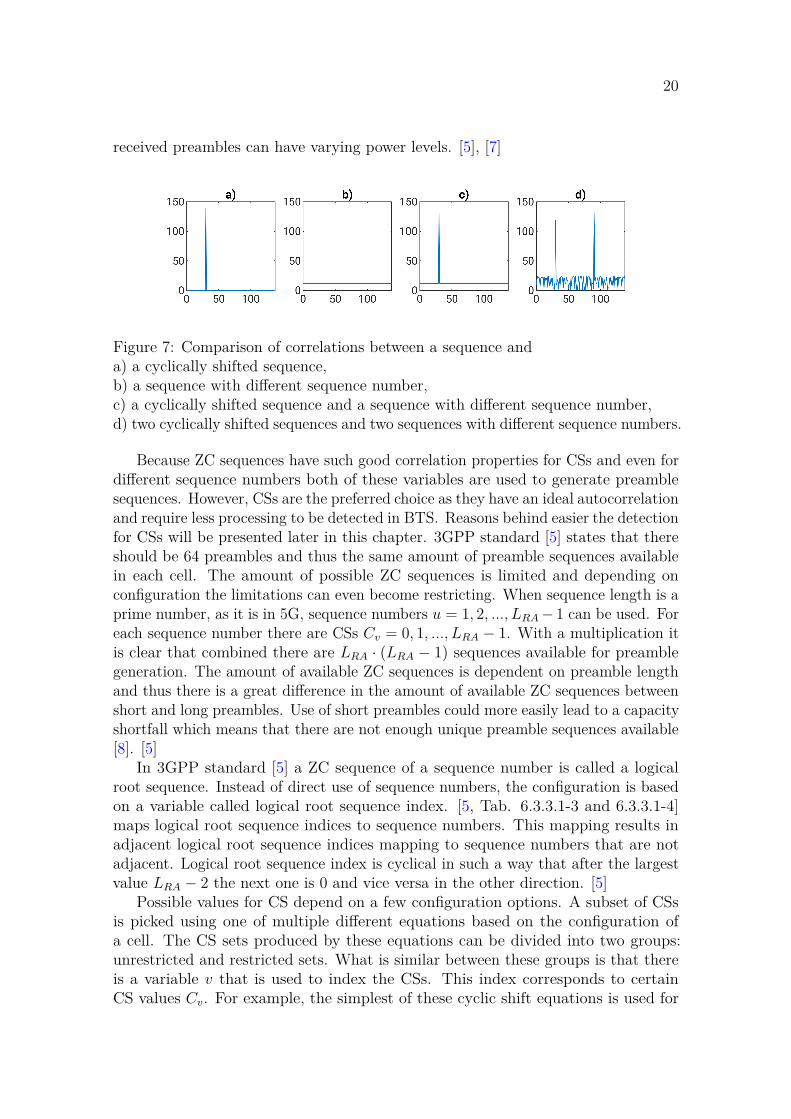
20
received preambles can have varying power levels. [5], [7]
Figure 7: Comparison of correlations between a sequence anda) a cyclically shifted sequence,b) a sequence with different sequence number,c) a cyclically shifted sequence and a sequence with different sequence number,d) two cyclically shifted sequences and two sequences with different sequence numbers.
Because ZC sequences have such good correlation properties for CSs and even fordifferent sequence numbers both of these variables are used to generate preamblesequences. However, CSs are the preferred choice as they have an ideal autocorrelationand require less processing to be detected in BTS. Reasons behind easier the detectionfor CSs will be presented later in this chapter. 3GPP standard [5] states that thereshould be 64 preambles and thus the same amount of preamble sequences availablein each cell. The amount of possible ZC sequences is limited and depending onconfiguration the limitations can even become restricting. When sequence length is aprime number, as it is in 5G, sequence numbers u = 1, 2, ..., LRA − 1 can be used. Foreach sequence number there are CSs Cv = 0, 1, ..., LRA − 1. With a multiplication itis clear that combined there are LRA · (LRA − 1) sequences available for preamblegeneration. The amount of available ZC sequences is dependent on preamble lengthand thus there is a great difference in the amount of available ZC sequences betweenshort and long preambles. Use of short preambles could more easily lead to a capacityshortfall which means that there are not enough unique preamble sequences available[8]. [5]
In 3GPP standard [5] a ZC sequence of a sequence number is called a logicalroot sequence. Instead of direct use of sequence numbers, the configuration is basedon a variable called logical root sequence index. [5, Tab. 6.3.3.1-3 and 6.3.3.1-4]maps logical root sequence indices to sequence numbers. This mapping results inadjacent logical root sequence indices mapping to sequence numbers that are notadjacent. Logical root sequence index is cyclical in such a way that after the largestvalue LRA − 2 the next one is 0 and vice versa in the other direction. [5]
Possible values for CS depend on a few configuration options. A subset of CSsis picked using one of multiple different equations based on the configuration ofa cell. The CS sets produced by these equations can be divided into two groups:unrestricted and restricted sets. What is similar between these groups is that thereis a variable v that is used to index the CSs. This index corresponds to certainCS values Cv. For example, the simplest of these cyclic shift equations is used for

21
unrestricted sets and it isCv = vNCS, (4)
where v = 0, 1, ..., [LRA/NCS] − 1 and NCS is a configuration variable that controlshow many samples apart the used CSs will be. A special case is when NCS is zeroand only zero CS is allowed from each logical root sequence. [5]
Restricted sets can only be used with long preambles and their aim is to improvepreamble detection when UEs move with high velocity which causes Doppler shift andthus more frequency errors. ZC sequences lose their ideal autocorrelation propertywhen there are frequency errors present but restricting the allowed CSs with certainequations can help keeping this effect under control. Unrestricted set is a set withouta special scheme for avoiding Doppler shift problems and for this reason the selectionof allowed CSs is a lot simpler than with restricted sets. Unrestricted sets can be usedfor both long and short preambles and are described by Equation 4. All unrestrictedsets use the same equation and configuration happens by changing NCS. However,NCS is not configured directly but through a zero-correlation zone (ZCZ) parameterwhich allows selecting certain NCS values depending on which kind of CS set is inuse. For restricted sets there are multiple equations to select allowed CSs but thoseare not presented in this thesis. [5], [7]
For every PRACH configuration 64 preambles have to be selected. Preamblesequence xu,v of length LRA is identified by sequence number u and index of CS v.The process of preamble sequence selection can be described in the following steps:
1. Generate a ZC sequence with a sequence number given by the logical rootsequence index.
2. Select CSs Cv from the generated ZC sequence in the order of index v. Stopwhen 64 preamble sequences are selected. If allowed CSs end before thatincrease logical root sequence index by one and go back to step one.
There is a configuration option that sets a starting value for logical root sequenceindex. The same subset of CSs is used for all logical root sequences. Based on thecell’s configuration this process can lead to preamble sequences that are all from thesame logical root sequence or from multiple. [5]
CSs of preambles should be separable from each other even when round-trip delay(RTD) varies between UEs and BTS. RTD measures how long it takes for a signalto propagate to a transceiver and back. Separability of CSs and ZCZ settings areclosely related to cell size. In initial access UEs and BTS do not know the distancebetween them. This means that propagation delay causes an UE to receive the SSBwith an unknown delay after the BTS sent it. The UE has to time its preambletransmission based on the arrival time of the SSB and thus there is an RTD-long,two times the propagation time, delay when the BTS receives the preamble. If thisdelay is longer than the CS step NCS the cyclically shifted preambles will not beorthogonal at the receiver. This leads to the concept of detection windows whichclassify perceived CSs at the receiver into different allowed CSs. Figure 8 shows anexample reception of preambles with the same sequence number and four differentCSs. Dashed red line shows how CSs are mixed if the cell’s configuration used too

22
Figure 8: Four ZCZs and preamble transmissions (same CS within each colour) withdifferent time delays. Dashed red line demonstrates how too small NCS can cause apreamble of long time delay to be mixed with a preamble with another CS.
small NCS in relation of the RTD. In conclusion, larger NCS allows more time forpropagation and thus larger cell size. [3]
2.3 Preambles and mapping to physical resourcesThis section connects the previous two sections and explains how preambles aregenerated from preamble sequences and mapped into the physical resources. First,generation of preambles from preamble sequences and available preamble formatsare discussed. Next topic is mapping the preambles into slots. Then guard periodaddition after PRACH by scheduler and placement the slots into subframes andframes are discussed. Finally, these topics wrapped up from UE’s point of view.
Generation of RACH preambles is based on preamble sequences, SC-FDMA andconfiguration options. A randomly chosen preamble sequence from the set of 64 isinput into SC-FDMA to transform it into a transmittable time-domain signal. Thistime-domain signal is then repeated as many times as the configuration demandsand finally a CP of configurable length is inserted in front of the repetitions. TheCP is only inserted in front of the first repetition if there are multiple. This is howRACH preambles are structured and generated. [3]
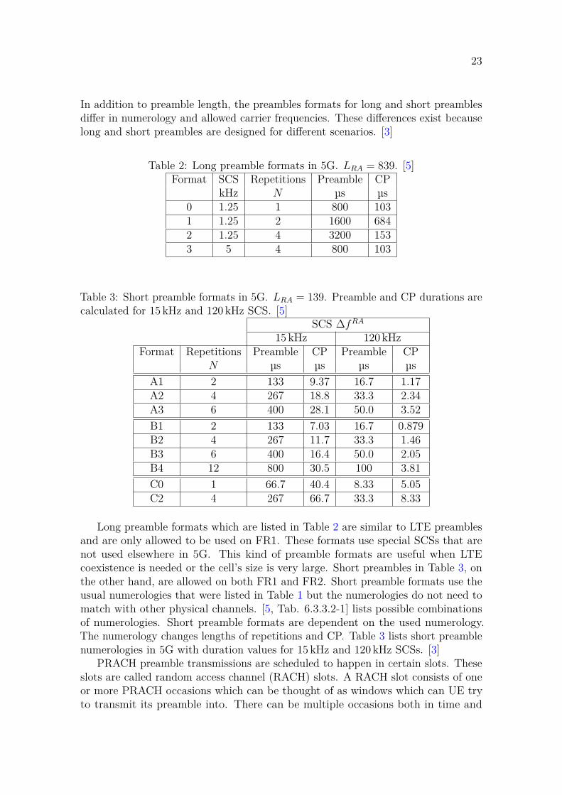
3GPP standard [5] specifies all possible values for the number of repetitions andCP length. There is a list of configurations called preamble formats which determinethe structure of a preamble. Preamble formats are divided into two groups based onpreamble length: long preambles with length 839 and short preambles with length 139.Table 2 lists preamble formats for long preambles and Table 3 for short preambles.
23
In addition to preamble length, the preambles formats for long and short preamblesdiffer in numerology and allowed carrier frequencies. These differences exist becauselong and short preambles are designed for different scenarios. [3]
Table 2: Long preamble formats in 5G. LRA = 839. [5]Format SCS Repetitions Preamble CP
kHz N µs µs0 1.25 1 800 1031 1.25 2 1600 6842 1.25 4 3200 1533 5 4 800 103
Table 3: Short preamble formats in 5G. LRA = 139. Preamble and CP durations arecalculated for 15 kHz and 120 kHz SCS. [5]
SCS ∆fRA
15 kHz 120 kHzFormat Repetitions Preamble CP Preamble CP
N µs µs µs µsA1 2 133 9.37 16.7 1.17A2 4 267 18.8 33.3 2.34A3 6 400 28.1 50.0 3.52B1 2 133 7.03 16.7 0.879B2 4 267 11.7 33.3 1.46B3 6 400 16.4 50.0 2.05B4 12 800 30.5 100 3.81C0 1 66.7 40.4 8.33 5.05C2 4 267 66.7 33.3 8.33
Long preamble formats which are listed in Table 2 are similar to LTE preamblesand are only allowed to be used on FR1. These formats use special SCSs that arenot used elsewhere in 5G. This kind of preamble formats are useful when LTEcoexistence is needed or the cell’s size is very large. Short preambles in Table 3, onthe other hand, are allowed on both FR1 and FR2. Short preamble formats use theusual numerologies that were listed in Table 1 but the numerologies do not need tomatch with other physical channels. [5, Tab. 6.3.3.2-1] lists possible combinationsof numerologies. Short preamble formats are dependent on the used numerology.The numerology changes lengths of repetitions and CP. Table 3 lists short preamblenumerologies in 5G with duration values for 15 kHz and 120 kHz SCSs. [3]
PRACH preamble transmissions are scheduled to happen in certain slots. Theseslots are called random access channel (RACH) slots. A RACH slot consists of oneor more PRACH occasions which can be thought of as windows which can UE tryto transmit its preamble into. There can be multiple occasions both in time and

24
frequency domains inside a single RACH slot. Time occasions mean occasions thathappen sequentially in time and frequency occasions mean occasions that are ondifferent subcarriers but occur at the same time. Configuration can simply specifyhow many frequency occasions there is in a RACH slot while the number of timeoccasions depends on preamble format. All preamble formats for long sequences haveonly a single time occasion because the preamble is too long for multiple to fit insidea single slot. On the other hand, preamble formats for short sequences can have oneor more time occasions. [3]
Frequency occasions in PRACH require a varying amount of RBs in the numerol-ogy of other physical channels. [5, Tab. 6.3.3.2-1] lists the number of RBs in differentcombinations of SCSs. These numbers can be calculated with SCSs and preamble’slength: A preamble needs as many subcarriers as it is long and using SCS of PRACHthe required bandwidth can be calculated. This bandwidth is then converted to otherphysical channels’ numerology by dividing it with the other physical channels’ SCS.
Length of a preamble in time domain is dependent on PRACH numerology’s SCSand the number of repetitions. One repetition takes a single symbol which is thereciprocal of SCS. Multiple repetitions consume multiple symbols. In addition totime needed for repetitions, CP length determined by the 3GPP standard [5] is addedto the sum. In the case of preamble formats for short preambles a single preamble isoften short enough such that multiple time occasions can happen in a single RACHslot. The number of time occasions for different preamble formats are listed in [5,Tab. 6.3.3.2-2, Tab. 6.3.3.2-3 and Tab. 6.3.3.2-4].
In contrast to being able to have multiple time occasions in a single RACH slot,long preamble formats 1 and 2 in Table 2 are longer than a slot. This is not aproblem because instead of being a hard limit for PRACH reception a RACH slotactually defines starting points for PRACH receptions. This definition is also neededwith short preambles because they can also go over a RACH slot due RTD. PRACHtransmissions do not overlap with other traffic because scheduler will provide a guardtime after each RACH slot. Guard time is not defined in 3GPP standard whichmeans that the scheduler can choose freely the guard time’s length based on e.g. cellsize and preamble format. [3]
RACH slots are scheduled based on certain rules which are listed in [5, Tab.6.3.3.2-2, Tab. 6.3.3.2-3 and Tab. 6.3.3.2-4]. The tables have many options perpreamble format for when the RACH slots happen. This is determined by twooptions: First option tells which frames have RACH slots. The option specifiesvariables for modulo operation on the frame’s number, e.g. every eighth or sixteenthframe. The second option lists in which subframes RACH slots occur when a framematches the first option. Starting symbol inside the slot for the occasions are alsospecified in the tables.
UE gets information about the previous mappings from SSB. SSB associates itselfwith a certain PRACH occasion: this includes frames, subframes, time occasions andfrequency occasions. UE might receive multiple different SSBs which associate withdifferent PRACH occasions. This could happen, for example, due to beamformingbeing in use which is discussed more in Section 2.5. At this point it is importantthat UE can select from multiple SSBs and PRACH occasions which one would be
25
the best. Then UE will construct the preamble using the configuration given in theselected SSB and by picking randomly from the 64 preamble options. Finally, UEtransmits the preamble at a certain time aiming to hit the specified PRACH occasionat the BTS.
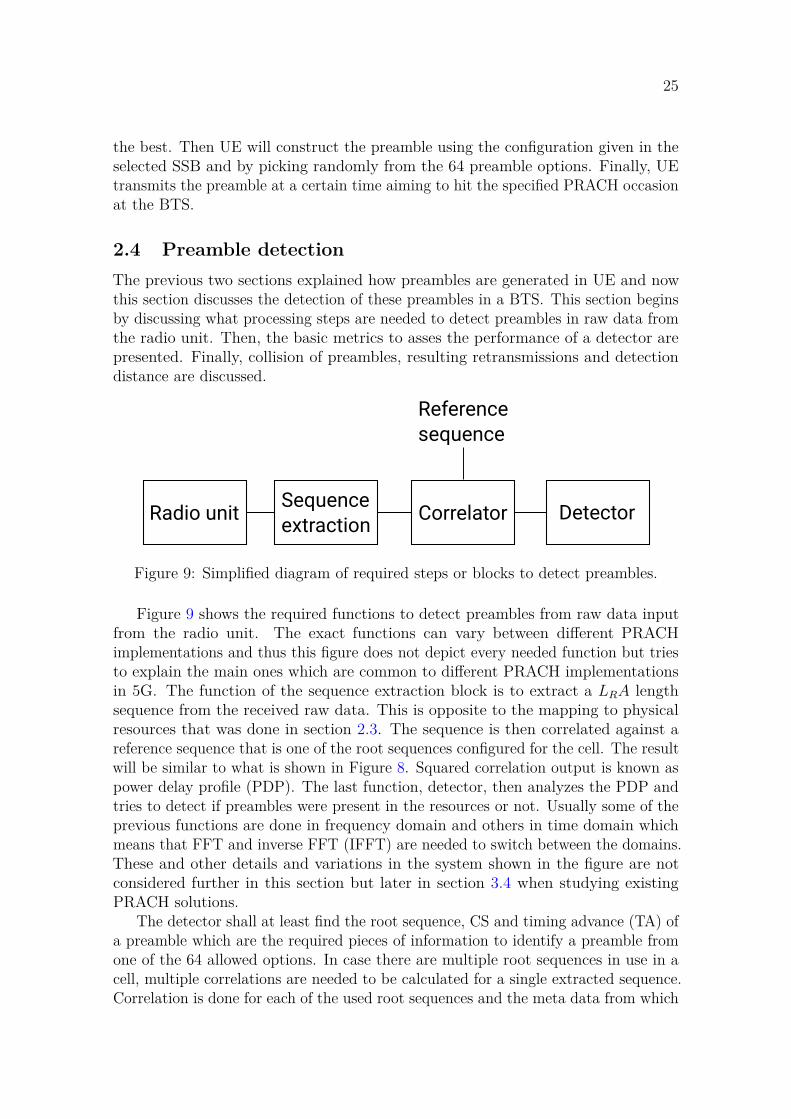
2.4 Preamble detectionThe previous two sections explained how preambles are generated in UE and nowthis section discusses the detection of these preambles in a BTS. This section beginsby discussing what processing steps are needed to detect preambles in raw data fromthe radio unit. Then, the basic metrics to asses the performance of a detector arepresented. Finally, collision of preambles, resulting retransmissions and detectiondistance are discussed.
Correlator Detector
Reference
sequence
Radio unitSequence
extraction
Figure 9: Simplified diagram of required steps or blocks to detect preambles.
Figure 9 shows the required functions to detect preambles from raw data inputfrom the radio unit. The exact functions can vary between different PRACHimplementations and thus this figure does not depict every needed function but triesto explain the main ones which are common to different PRACH implementationsin 5G. The function of the sequence extraction block is to extract a LRA lengthsequence from the received raw data. This is opposite to the mapping to physicalresources that was done in section 2.3. The sequence is then correlated against areference sequence that is one of the root sequences configured for the cell. The resultwill be similar to what is shown in Figure 8. Squared correlation output is known aspower delay profile (PDP). The last function, detector, then analyzes the PDP andtries to detect if preambles were present in the resources or not. Usually some of theprevious functions are done in frequency domain and others in time domain whichmeans that FFT and inverse FFT (IFFT) are needed to switch between the domains.These and other details and variations in the system shown in the figure are notconsidered further in this section but later in section 3.4 when studying existingPRACH solutions.
The detector shall at least find the root sequence, CS and timing advance (TA) ofa preamble which are the required pieces of information to identify a preamble fromone of the 64 allowed options. In case there are multiple root sequences in use in acell, multiple correlations are needed to be calculated for a single extracted sequence.Correlation is done for each of the used root sequences and the meta data from which

26
correlation a detection is made from is used to find out the root sequence for thedetected preamble. CS and TA are calculated by the detector while detecting thepreambles. While not necessarily mandatory, power or other similar measurement ofthe strength of a detected preamble is useful information for the detector to find outand report with the detection.
Two very important metrics should be considered when assessing performance ofa PRACH detector: missed and false detection rates. A missed detection means thatan UE sent a correct preamble but the detector did not detect it. A false detectionmeans that an UE did not send a preamble but the detector still detected something.These false detections can also be called ghost preambles. These two rates are the twomost important metrics for PRACH performance. Sadly there is a trade-off betweenthese two: Making a detector more sensitive decreases the missed detection ratebut at the same time increases the amount of false detections. Lowering a detectorssensitivity makes false detection fewer but causes real preambles to be missed moreoften. Designing better detector algorithms and finding ways to improve the qualityof the correlation output through e.g. improving signal-to-noise ratio (SNR) in theto-be-correlated sequence are ways to improve both of these two metrics.
There can be multiple repetitions in a PRACH preamble and a BTS might havemultiple antennas or antenna polarizations. Detections needs to be done similarly inall of these which would require a huge amount of processing. To avoid this, combiningis done to process more of the previous at once. For example, repetitions can besummed such that only a single detection needs to be done. This works because anUE transmits the same information in each of the repetitions and thus only the noiseand interference vary between the repetitions. There are two types of combining:coherent and non-coherent. Coherent combining is combining with phase informationincluded and non-coherent is without phase information. [7] Coherent combining cancause phase error in the combined signal if phase varies between the sources. Thisis, for example, relevant in a PRACH detector if multiple repetitions are combinedcoherently and propagation conditions change between the repetitions. Phase errorin this example is not fatal to the performance and thus coherent combining can beused in PRACH in addition to non-coherent combining which does not have thisphase error issue. In general coherent combining would be favourable to reduce theamount of processing but the trade-off needs to be considered separately for e.g.repetitions and antennas. This is studied further in Section 3.4.
An UE randomly transmits one of the 64 available preambles. Unfortunatelymultiple UEs may transmit the same preamble during the same RACH slot. As aresult, these preambles will occur in the same ZCZ in the PDP and cause a collisionof preambles. Even if the detector could separate two spikes inside the same cyclicshift window, RAR is identified by preamble’s logical root sequence and cyclic shift,and it is not possible to send own RARs for both the UEs. Both UEs consider thesent RAR theirs and continue with the RA process which will eventually drop oneof the UEs for because of the preamble collision. This collision resolving is calledcontention and there are multiple ways to handle the issue. In the case of collisionthe dropped UE will retry after a small delay with a new randomly chosen preamble.A retry will also occur if an UE does not receive RAR for some other reason within a

27
certain time period. First preamble transmission is done with the lowest power andwith each retry the transmission power is increased as set by configuration. This iscalled power ramping and its aim is to conserve energy by using smallest possibletransmission power. [3]
The selection of ZCZ has a big effect on how far away UEs the can be successfullydetected. As shown in Figure 8, too large time delay in a preamble will cause thedetection result to be seen in an incorrect ZCZ. UE’s distance from the PRACHdetector and the preambles propagation time through the air which is directly relatedto RTD causes this issue. This means that larger ZCZ results in larger detectionrange. There’s a notable difference between long and short PRACH formats here: along format sequence is multiple times longer than the short format one and thuscan support a lot larger detection range.
2.5 BeamformingThe topic of this section is beamforming in 5G and PRACH. The status of beam-forming in 5G is discussed first. Then, different types of beamforming are presentedto give a general understanding of different beamforming options. After the types ofbeamforming, their use cases and acquisition of the needed information for beam-forming are discussed shortly. Finally, the effect of beamforming on PRACH andwhat kind of beamforming could be used in PRACH are discussed.
In 5g, the importance of multiple-input and multiple-output (MIMO) and beam-forming is increasing compared to LTE. These two offer longer cell range for path-loss-limited very high frequency networks and improved spectral efficiency in general.MIMO means the use of multiple antennas in transmitters and receivers and beam-forming means directing the transmissions into certain sectors using these multipleantennas. A MIMO channel with beamforming is presented mathematically in [9]. Atransmitter with beamforming is described with
s = Md, (5)
where d is data signal, M is beamforming matrix and s is the transmitted signal. Areceiver then receives the signal
x = Hs + n, (6)
where H describes the radio channel and n is noise. The processing system in thereceiver will then undo the beamforming to get the signal back to original
d = Dx = D(HMd + n), (7)
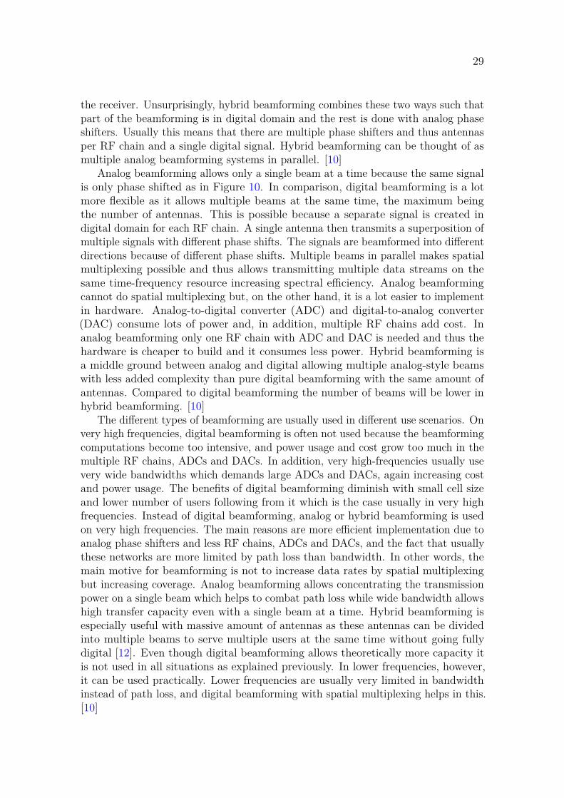
where D is a matrix for undoing the beamforming. The beamforming matricesphase shift the antenna signals and can in addition modify the amplitudes but thisisn’t required in a simple case. There are multiple ways to construct the matriceswith different capabilities, performance and hardware needs. Phase shift makes theradiation patterns interfere with each other and thus results in constructive anddestructive interference areas. The constructive area is the now formed beam. Figure

28
Figure 10: Beamforming with phased antenna array. [11]
10 visualizes how the interference of an antenna array with a constant phase differencebetween each antenna forms a beam. [10]
The previous equations can be realized in many different ways. Beamformingcan be done in a digital, analog or hybrid manner. Hybrid is a mix of the first two.In analog beamforming the beamforming matrices are realised using analog phaseshifters or delays. Delay is applied the same for all frequencies while phase shift canvary based on frequency. Delay is measured in time and phase shift in angle but inthe end these two are the same thing now so delay can be considered as a specific kindof phase shift. In a transmitter these are placed in radio frequency (RF) part of thesystem such that a single RF signal is split into multiple phase shifters from whichthe phased shifted signals to the antennas. The antennas will transmit the signalwith different phase shifts and thus the transmission is beamformed. In a receiver,the phase shifters are also situated in the RF and their output is combined into asingle signal before conversion into digital domain. In digital beamforming, the phaseshifting is done in digital domain instead of using analog phase shifters. This meansthat there will be an own RF chain for every antenna both in the transmitter and
29
the receiver. Unsurprisingly, hybrid beamforming combines these two ways such thatpart of the beamforming is in digital domain and the rest is done with analog phaseshifters. Usually this means that there are multiple phase shifters and thus antennasper RF chain and a single digital signal. Hybrid beamforming can be thought of asmultiple analog beamforming systems in parallel. [10]
Analog beamforming allows only a single beam at a time because the same signalis only phase shifted as in Figure 10. In comparison, digital beamforming is a lotmore flexible as it allows multiple beams at the same time, the maximum beingthe number of antennas. This is possible because a separate signal is created indigital domain for each RF chain. A single antenna then transmits a superposition ofmultiple signals with different phase shifts. The signals are beamformed into differentdirections because of different phase shifts. Multiple beams in parallel makes spatialmultiplexing possible and thus allows transmitting multiple data streams on thesame time-frequency resource increasing spectral efficiency. Analog beamformingcannot do spatial multiplexing but, on the other hand, it is a lot easier to implementin hardware. Analog-to-digital converter (ADC) and digital-to-analog converter(DAC) consume lots of power and, in addition, multiple RF chains add cost. Inanalog beamforming only one RF chain with ADC and DAC is needed and thus thehardware is cheaper to build and it consumes less power. Hybrid beamforming isa middle ground between analog and digital allowing multiple analog-style beamswith less added complexity than pure digital beamforming with the same amount ofantennas. Compared to digital beamforming the number of beams will be lower inhybrid beamforming. [10]
The different types of beamforming are usually used in different use scenarios. Onvery high frequencies, digital beamforming is often not used because the beamformingcomputations become too intensive, and power usage and cost grow too much in themultiple RF chains, ADCs and DACs. In addition, very high-frequencies usually usevery wide bandwidths which demands large ADCs and DACs, again increasing costand power usage. The benefits of digital beamforming diminish with small cell sizeand lower number of users following from it which is the case usually in very highfrequencies. Instead of digital beamforming, analog or hybrid beamforming is usedon very high frequencies. The main reasons are more efficient implementation due toanalog phase shifters and less RF chains, ADCs and DACs, and the fact that usuallythese networks are more limited by path loss than bandwidth. In other words, themain motive for beamforming is not to increase data rates by spatial multiplexingbut increasing coverage. Analog beamforming allows concentrating the transmissionpower on a single beam which helps to combat path loss while wide bandwidth allowshigh transfer capacity even with a single beam at a time. Hybrid beamforming isespecially useful with massive amount of antennas as these antennas can be dividedinto multiple beams to serve multiple users at the same time without going fullydigital [12]. Even though digital beamforming allows theoretically more capacity itis not used in all situations as explained previously. In lower frequencies, however,it can be used practically. Lower frequencies are usually very limited in bandwidthinstead of path loss, and digital beamforming with spatial multiplexing helps in this.[10]
30
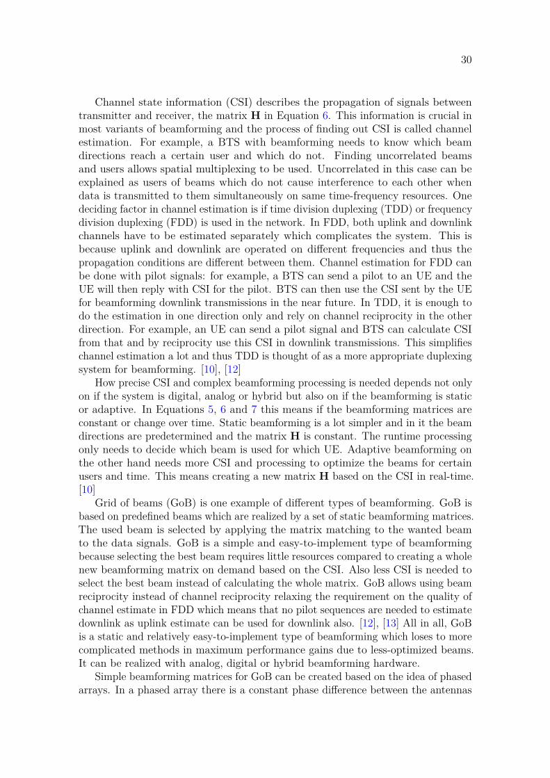
Channel state information (CSI) describes the propagation of signals betweentransmitter and receiver, the matrix H in Equation 6. This information is crucial inmost variants of beamforming and the process of finding out CSI is called channelestimation. For example, a BTS with beamforming needs to know which beamdirections reach a certain user and which do not. Finding uncorrelated beamsand users allows spatial multiplexing to be used. Uncorrelated in this case can beexplained as users of beams which do not cause interference to each other whendata is transmitted to them simultaneously on same time-frequency resources. Onedeciding factor in channel estimation is if time division duplexing (TDD) or frequencydivision duplexing (FDD) is used in the network. In FDD, both uplink and downlinkchannels have to be estimated separately which complicates the system. This isbecause uplink and downlink are operated on different frequencies and thus thepropagation conditions are different between them. Channel estimation for FDD canbe done with pilot signals: for example, a BTS can send a pilot to an UE and theUE will then reply with CSI for the pilot. BTS can then use the CSI sent by the UEfor beamforming downlink transmissions in the near future. In TDD, it is enough todo the estimation in one direction only and rely on channel reciprocity in the otherdirection. For example, an UE can send a pilot signal and BTS can calculate CSIfrom that and by reciprocity use this CSI in downlink transmissions. This simplifieschannel estimation a lot and thus TDD is thought of as a more appropriate duplexingsystem for beamforming. [10], [12]
How precise CSI and complex beamforming processing is needed depends not onlyon if the system is digital, analog or hybrid but also on if the beamforming is staticor adaptive. In Equations 5, 6 and 7 this means if the beamforming matrices areconstant or change over time. Static beamforming is a lot simpler and in it the beamdirections are predetermined and the matrix H is constant. The runtime processingonly needs to decide which beam is used for which UE. Adaptive beamforming onthe other hand needs more CSI and processing to optimize the beams for certainusers and time. This means creating a new matrix H based on the CSI in real-time.[10]
Grid of beams (GoB) is one example of different types of beamforming. GoB isbased on predefined beams which are realized by a set of static beamforming matrices.The used beam is selected by applying the matrix matching to the wanted beamto the data signals. GoB is a simple and easy-to-implement type of beamformingbecause selecting the best beam requires little resources compared to creating a wholenew beamforming matrix on demand based on the CSI. Also less CSI is needed toselect the best beam instead of calculating the whole matrix. GoB allows using beamreciprocity instead of channel reciprocity relaxing the requirement on the quality ofchannel estimate in FDD which means that no pilot sequences are needed to estimatedownlink as uplink estimate can be used for downlink also. [12], [13] All in all, GoBis a static and relatively easy-to-implement type of beamforming which loses to morecomplicated methods in maximum performance gains due to less-optimized beams.It can be realized with analog, digital or hybrid beamforming hardware.
Simple beamforming matrices for GoB can be created based on the idea of phasedarrays. In a phased array there is a constant phase difference between the antennas

31
which results in a single directed beam. This is visualized in Figure 10. GoBbeamforming can be presented mathematically as
y = Gx =
⎡⎢⎢⎢⎢⎣g11 g12 g13 . . . g1N
g21 g22 g23 . . . g2N... ... ... . . . ...
gM1 gM2 gM3 . . . gMN
⎤⎥⎥⎥⎥⎦⎡⎢⎢⎢⎢⎣
x11 x12 x13 . . . x1L
x21 x22 x23 . . . x2L... ... ... . . . ...
xN1 xN2 xN3 . . . xNL
⎤⎥⎥⎥⎥⎦ , (8)
where y is a matrix of the beamformed signals, G the beamforming matrix and xa matrix of input signals. Matrices y and x are of size N × L such that N is thenumber of antennas, that is the number of signals, and L is the length of a signalwhich does not have effect on the result. Beamforming can be calculated sample bysample (L = 1) or in chunks (L > 1) and the result will be the same in either case.The beamforming matrix G is of size M × N such M is the number of beams. Theresult y will have M rows each of which consists of the sum of phase-adjusted inputsignals. The length of these rows naturally matches L. With a simplification L = 1the matrix y will become
y =
⎡⎢⎢⎢⎢⎣g11x11 + g12x21 + · · · + g1NxN1g21x11 + g22x21 + · · · + g2NxN1
...gM1x11 + gM2x21 + · · · + gMNxN1
⎤⎥⎥⎥⎥⎦ . (9)
Here it can be seen that each of the rows are adjusted with phase-factors fromdifferent rows of the beamforming matrix G. In analog beamforming only a singleset of phase shifts can be used at once which would mean selecting one of the rowsfrom the beamforming matrix. In digital beamforming all beams can be calculatedsimultaneously.
Beamforming can provide multiple benefits to PRACH. In addition to the usualinformation about which preamble was detected and with what power level, spatialestimate can be provided by the PRACH detector with the use of beamforming.This spatial information can used as initial CSI for beamforming of downlink traffic,for example RAR. Depending on the PRACH implementation it can be possible tospatially separate preambles sent by UEs in different directions which would havecollided without beamforming and spatial separation of the preambles in detector.Similarly to beamforming in other channels, array gain can provide better SNRleading to better detection performance in PRACH. While beamforming certainlyprovides advantages in PRACH it also increases the amount of processing requiredto detect the preambles.

32
3 ImplementationThis chapter describes the PRACH implementation that is done in this thesis, andwhat kind of project the implementation is a part of. First, section 3.1 introduces thelarger project and gives some context how the PRACH implementation fits into that.Section 3.2 continues by presenting the hardware for the implementation, and thetools and work flow for the hardware. Section 3.3 discusses the requirements for theimplementation. Then, state-of-the-art solutions for PRACH are studied in section3.4 before finally discussing the resulting design of the implementation in section 3.5.
3.1 Project descriptionThis section aims to give an overall view of what is implemented in this thesis andhow that is done. To start, the larger project that this PRACH implementationis a part of is presented shortly and is compared to a generic model of a 5G BTS.Next, the PRACH implementation is presented with the help of the previous context.Finally, implementation process and methods are discussed.
The PRACH implementation in this thesis is done as a part of a research radioproject which aims to study beamforming and other algorithms for a 5G-compliantBTS. Main goal in studying algorithms for beamforming and some other purposes isto increase the performance of a BTS. A BTS consists of multiple different hardwareunits and a large amount of different functionalities in those which means thatimplementing everything from scratch is a massive effort. For this reason alreadyexisting implementations are reused when possible to fulfil functionalities which arenot in the focus of this project’s goals.
A generic BTS for 5G consist of centralized, distributed and remote units [14].Remote unit implements a radio to communicate with an UE and RF processingfor the radio while distributed and centralized units implement baseband processing.Baseband processing is split between centralized and distributed units such that lowertransfer layers are in the distributed unit and higher layers are in the centralized unit.The centralized unit is connected to the core network over which communication canhappen to other base stations and, for example, the internet. Figure 11 visualizesthe different units and connections between them.
Figure 11: Centralized, distributed and remote units form a 5G BTS.
Separate centralized and distributed units are a new addition in 5G. In LTE aBTS consisted of remote and baseband units. There is no standard about whichfunctionality should reside in centralized or distributed units and thus it is a choice

33
left to be decided per implementation. Some baseband processing can be movedfrom distributed unit to remote unit even though 5G standard doesn’t consider thatoption. [15] How the functionality is split between the units has naturally an effecton what kind of data needs to be transferred over the interfaces between the units.The choice of different splits between the units is an important design decision andhas large effect on e.g. what kind of hardware configurations are needed for the unitsand what sort of interfaces can be used between the units.
Centralized and distributed units are named after how they are assumed to belocated in a generic 5G system. A centralized unit is meant to be located away froma traditional BTS site into a centralized location. Only the distributed and remoteunits would be there at the BTS site. A single centralized unit would then be usedto serve multiple different BTS sites which can provide benefits in for example moreefficient use of hardware and easier network maintenance. A new development inmobile communications is the use of cloud for baseband processing. Centralizedunit is the easiest one to be moved into the cloud because most of the time-criticalprocessing, which often needs specialized hardware, is done in the distributed andremote units. Also because a single centralized unit could be serving multiple basestation sites the scalability benefits of cloud would be easier to achieve.
As mentioned, the main focus of this project is on beamforming and the radiounit side of processing. When thinking about the generic 5G BTS model in Figure11, it can be noticed the main focus of this project is on the remote and distributedunits. From transmission layer point of view the focus is on layer 1 which is thelowest layer in 5G and implements the hardware-level functionality. This means thatreuse of earlier implementation in this project is most significant in the functionalityabove layer 1 which is in centralized and distributed units. The exact division is ofcourse dependent on the splits. In this project lower parts of layer 1 are implementedin the remote unit and that is where the PRACH implementation is located in. Forthis reason, this thesis will focus on the remote unit and other units are not discussedfurther.
The aim in this thesis is to implement a 5G-compliant PRACH implementationwhich should be scalable, configurable and done in a resource-efficient manner.Scalability and configurability are important so that supporting the vast configurationsin 5G would be possible with as minimal changes in the PRACH implementation aspossible. Resource-efficiency is important in saving the FPGA’s resources becausethose are needed for implementations of other functionalities of the remote unit. ThisPRACH implementation will also include support for beamforming as one of themains goals of this project is the study of beamforming. Even though the focus is onbeamforming of other channels than PRACH, adding support for it will come withfairly low cost as PRACH uses the same hardware than the other channels.
The remote unit board has a Xilinx UltraScale+ XCZU21DR FPGA and it is thehardware that is used in the PRACH implementation. The FPGA will eventually havelots of other functionality and this PRACH implementation will be very small partof the complete FPGA design. Two other important topics for this implementationare antenna configuration and hardware for beamforming. The remote unit has eightdual-polarized antennas and no hardware for analog beamforming, e.g. ability to

34
phase shift per-antenna signals in analog domain. This means that beamforming isdone digitally which allows a lot of options for beamforming. It is also specified thatthe beamforming in this PRACH will be of GoB-style.
The implementation in this thesis is done in the following steps:
• Study existing PRACH solutions in literature.
• Create a Matlab simulation to help in designing the implementation and verifythat the final design should work.
• Implement the design in VHDL.
• Test that the VHDL design matches the Matlab simulation results.
These steps also describe the method of this thesis. The working order also followsthese steps because the previous one is practically a pre-requisite for the next step.Studying the literature and creating the Matlab simulation can steps can have someoverlap which allows for the process to be a bit iterative. Earlier testing in Matlabsimulation can be used to direct the research. Later steps have to be done quitesequentially and they are based on the typical FPGA design flow. Different parts orblocks of the complete PRACH design can be implemented quite independently ofeach other and tested separately which helps in verifying if the written VHDL codeis working or not.
3.2 Xilinx UltraScale+ XCZU21DRThis section will present the Xilinx UltraScale+ XCZU21DR FPGA which is usedin this implementation, its architecture and the development tools for it. TheFPGA consists of programmable logic which is used to implement the custom design,processing subsystem which has general-purpose CPUs for running software, andsome application-specific hardware blocks. These are discussed first in this section.Then, the Xilinx FPGA development tool, Vivado, and the design flow from VHDLdesign to bitstream are presented.
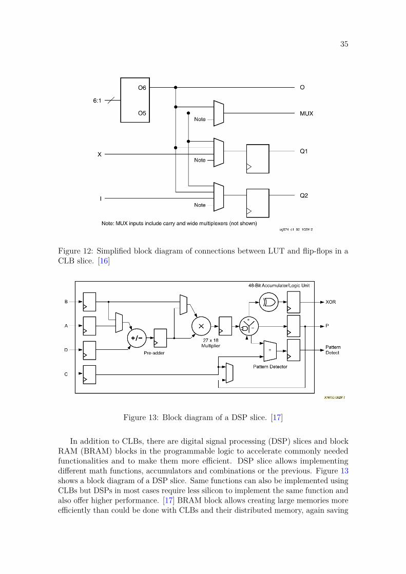
The combinatorial and sequential circuits in programmable logic are mainlyrealized with configurable logic blocks (CLB). In UltraScale+ architecture each CLBcontains one slice which can be of two different slice types: SLICEL or SLICEM.Both of these slice types contain 8 look-up tables (LUT), 16 flip-flops and muxers.Figure 12 shows how a LUT is connected to two flip-flops through a set of muxers.There are 8 in-parallel copies of this structure in a single slice and the parallelstructures are connected together with more muxers and an 8-bit carry chain. ASLICEL is a slice for implementing logic and it contains the aforementioned elements.A SLICEM adds the ability to use the LUTs as distributed random access memory(RAM) or shift registers in addition to the SLICEL functionality. Many kinds oflogic functions can be implemented by programming the LUT memory contents,connecting a varying amount of LUTs together in varying ways using the muxersand using different combinations of input signals to control all these elements. [16]
35
Figure 12: Simplified block diagram of connections between LUT and flip-flops in aCLB slice. [16]
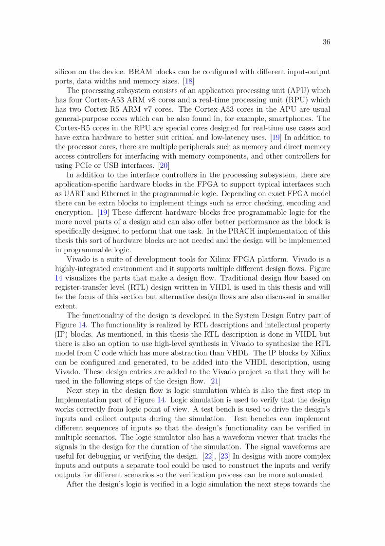
Figure 13: Block diagram of a DSP slice. [17]
In addition to CLBs, there are digital signal processing (DSP) slices and blockRAM (BRAM) blocks in the programmable logic to accelerate commonly neededfunctionalities and to make them more efficient. DSP slice allows implementingdifferent math functions, accumulators and combinations or the previous. Figure 13shows a block diagram of a DSP slice. Same functions can also be implemented usingCLBs but DSPs in most cases require less silicon to implement the same function andalso offer higher performance. [17] BRAM block allows creating large memories moreefficiently than could be done with CLBs and their distributed memory, again saving
36
silicon on the device. BRAM blocks can be configured with different input-outputports, data widths and memory sizes. [18]
The processing subsystem consists of an application processing unit (APU) whichhas four Cortex-A53 ARM v8 cores and a real-time processing unit (RPU) whichhas two Cortex-R5 ARM v7 cores. The Cortex-A53 cores in the APU are usualgeneral-purpose cores which can be also found in, for example, smartphones. TheCortex-R5 cores in the RPU are special cores designed for real-time use cases andhave extra hardware to better suit critical and low-latency uses. [19] In addition tothe processor cores, there are multiple peripherals such as memory and direct memoryaccess controllers for interfacing with memory components, and other controllers forusing PCIe or USB interfaces. [20]
In addition to the interface controllers in the processing subsystem, there areapplication-specific hardware blocks in the FPGA to support typical interfaces suchas UART and Ethernet in the programmable logic. Depending on exact FPGA modelthere can be extra blocks to implement things such as error checking, encoding andencryption. [19] These different hardware blocks free programmable logic for themore novel parts of a design and can also offer better performance as the block isspecifically designed to perform that one task. In the PRACH implementation of thisthesis this sort of hardware blocks are not needed and the design will be implementedin programmable logic.
Vivado is a suite of development tools for Xilinx FPGA platform. Vivado is ahighly-integrated environment and it supports multiple different design flows. Figure14 visualizes the parts that make a design flow. Traditional design flow based onregister-transfer level (RTL) design written in VHDL is used in this thesis and willbe the focus of this section but alternative design flows are also discussed in smallerextent.
The functionality of the design is developed in the System Design Entry part ofFigure 14. The functionality is realized by RTL descriptions and intellectual property(IP) blocks. As mentioned, in this thesis the RTL description is done in VHDL butthere is also an option to use high-level synthesis in Vivado to synthesize the RTLmodel from C code which has more abstraction than VHDL. The IP blocks by Xilinxcan be configured and generated, to be added into the VHDL description, usingVivado. These design entries are added to the Vivado project so that they will beused in the following steps of the design flow. [21]
Next step in the design flow is logic simulation which is also the first step inImplementation part of Figure 14. Logic simulation is used to verify that the designworks correctly from logic point of view. A test bench is used to drive the design’sinputs and collect outputs during the simulation. Test benches can implementdifferent sequences of inputs so that the design’s functionality can be verified inmultiple scenarios. The logic simulator also has a waveform viewer that tracks thesignals in the design for the duration of the simulation. The signal waveforms areuseful for debugging or verifying the design. [22], [23] In designs with more complexinputs and outputs a separate tool could be used to construct the inputs and verifyoutputs for different scenarios so the verification process can be more automated.
After the design’s logic is verified in a logic simulation the next steps towards the

37
Figure 14: Vivado design flow. [21]
design’s realization on FPGA are logic synthesis and implementation. Logic synthesisis a process in which the RTL descriptions are transformed into a netlist whichdescribes the design using logic gates and flip-flops [22], [24]. In implementation thenetlist is mapped into hardware elements which are available on the FPGA such asLUTs. The functionality of the netlist is first described using the available hardwareelements and then the elements are placed and routed on the FPGA hardware sothat the result actually reflects how the hardware is on the device. [22], [25]
Logic synthesis and implementation are automated in Vivado and performedby software as they are in most contemporary design tools. There is no single oroptimal way to do either logic synthesis nor implementation so the designer can giveconstraints to the software to guide and limit the processes. Examples of constraintsare the type of FPGA which limits the available resources and the ability to connectthem, clock frequency which limits how much time there is between a pair of flip-flops,and options to optimize towards certain goals such as small size on the FPGA or
38
how much the software can have freedom to optimize the design. Place and routeespecially is a complex problem to solve and as a result the process has randomnessmeaning that the output varies between runs. To find the best place and routeresult the process may need to be run multiple times and different constraints canbe explored. In some cases the process can even fail to fulfil the constraints andwork incorrectly. This becomes more probable when the design grows larger in sizeand reaches close to the FPGA’s limits. [22] In this thesis the implementation is notlarge enough so that these things would be an issue. Also, only the PRACH block issynthesized in this thesis so no effort will be put into optimization of the synthesisand implementation results.
Different sorts of verification can and should be done after both logic synthesisand implementation to make sure that the automated processes have produced aworking output. For example timing analysis and design rule check can be performedto verify the design. [26] After the design has been synthesized, implemented and allverification is done a bitstream can be generated. Bitstream describes the design ina format readable by an actual FPGA. The bitstream is then uploaded and verifiedon an actual FPGA. Bitstream generation and testing on real hardware are out ofscope of this thesis.
3.3 RequirementsThe PRACH implementation in this thesis should be 5G compliant, scalable andresource-efficient. These three are the main design goals for this implementationbut they are not unordinary qualities for a PRACH implementation. Unfortunately,there is no concrete specification for how much FPGA resources can be consumed bythe PRACH implementation due to the early status of the FPGA implementationpart of the project. The interesting feature in this implementation is the addition ofGoB beamforming into the PRACH. The 5G standard for PRACH, the requirementto have GoB beamforming and the used FPGA hardware provide the main guidelinesto what kind of options there are in the implementation and the design goals ofscalability and resource-efficiency are then used to select from the options. Thissection discusses the requirements that are specified for the design. First the goalsfor the implementation are discussed and after that, the configuration options thatare used to test the implementation in this thesis.
GoB beamforming is possible to be used in this implementation because of theeight dual polarized antennas. The beamforming implementation is digital as it is inthe rest of the system. The use of analog beamforming is not possible because therequired hardware for it is not available on the remote unit board. GoB beamformingis implemented in this thesis such that all beams beams are scanned for PRACHpreambles simultaneously. Another option would have been to scan only a certainbeam per a certain time as in analog beamforming but simultaneous system wasselected for this implementation. The advantage in simultaneous scanning of all beamscompared to scanning a single beam per certain time is naturally that preamblesfrom all directions can be detected at a single time. This means that fewer time slotsneed to be allocated for PRACH. For example, if there are four beams in use, four

39
time slots would be needed for PRACH to detect preambles in the whole coveredarea instead of just one. A disadvantage in simultaneous detection of beams is thatit requires more processing resources.
PRACH in this implementation provides the system’s other parts informationabout detected power, RTD estimate and which of the available preambles wasdetected. Because GoB is used this information is provided per beam for everydetection. Other system components can use this information in different ways forcreating the initial estimate for beamforming. This means that the beamformingfunctionality in this implementation is only about collecting the detection results perbeam and the beamforming algorithms itself are not discussed in this thesis. Thesealgorithms would use the per-beam information in beamforming of the transmissionsthat come after a PRACH preamble. Beamforming can provide improved detectionperformance in the PRACH itself because of focusing the detection in a beam withcombined power from multiple antennas. Analysis of this performance increase inPRACH is not part of this thesis.
The PRACH implementation in this thesis is targeted to work in a 5G-compliantsystem. Thus, the 3GPP’s 5G standard describes what the PRACH implementationshould do. The standard for PRACH is flexible like 5G generally is and there aremany configuration options in the standard for different types of use scenarios. Thesystem developed in this project will be designed for a certain use scenario whichmeans that supporting all the different configuration variations that are presentedin the standard is not needed. The design goal of resource-efficiency and preferenceto keep the implementation simple mean that it is better to focus on a subset ofthe configuration variations. The design goal of scalability means that while only asubset of the configuration variations are supported it should be kept in mind duringthe implementation that there could be need to extend the implementation in thefuture to support different use scenarios.
The use scenario in this project requires FR1, unpaired spectrum and TDD. SCSon other channels is 15/30 kHz which is also used in PRACH. It would be possibleto use either short or long preambles in PRACH based on the 5G standards butshort preambles are selected for this use scenario and thus the implementation. Thisis an important limitation regarding the resource usage of the implementation sosupporting both if it is not needed would be wasteful. With short preambles thereare options to use multiple different SCS options which do not need to match whatis used in the other channels but now the same 15/30 kHz is used also for PRACH.Using the same SCS on all channels can help make the implementation simpler insome parts of the design as PRACH can reuse more parts of the system which areneeded for other channels.
As the configuration set for this implementation is wanted to be kept small andthere are no requirements for especially high PRACH capacity only a single frequencyoccasion is supported. Preamble format A2 is selected for this implementation.Preamble format A2 has four repetitions which means that three time occasionscan be fit into a single PRACH slot. There is no requirement which PRACHconfiguration indices for format A2 should be supported but the differences betweendifferent configuration indices in the case of A2 are only in which subframes PRACH

40
is to be scheduled and what is the starting symbol in a PRACH slot. Support for thesetwo parameters are not difficult to be implemented in a configurable way and thusall of them will be supported in this implementation. Because this implementationis wanted to scalable the design should be make configurable or easily extensible forother preamble formats than A2 if possible.
The range in which PRACH is required to detect preambles in this implementationis around 1 km. This range limits what ZCZs can be used. Short preambles supportonly the simplest way to select CSs so restricted sets for CS are not supported inthis implementation. As was explained in section 2.2, using a large ZCZ meansthat more root sequences are needed to get 64 unique preamble sequences. Moreroot sequences means more processing needed to detect the preambles and thus thesmallest possible CS size is preferred. However the requirement of 1 km detectionrange sets the minimum size of CS and thus the required ZCZ configuration. For1 km range in short PRACH format NCS 34 needs to be selected from the optionsdefined in the standard [5, Tab. 6.3.3.1-7]. This means that four ZCZs can be fit intoone 139-sample preamble and to get the full 64 preamble options 16 root sequencesneed to be supported. The detector needs to calculate the correlation separately forall 16 root sequences.
The requirements can be divided into two groups based on which sort of effectthey have on the implementation: those that affect the processing power requirementsand those that do not. Main requirements that affect the processing power needsin the detector are preamble format and the amount of root sequences. Preambleformat sets the time schedule for incoming preambles, repetitions and time occasions.Amount of root sequences affects how much processing power is needed to handle onetime occasion. The implementation must be capable of doing all required detectionprocessing during the time limits. One example for parameter that doesn’t affect theneed for processing power is PRACH configuration index which selects things likewhen PRACH slots occur in the context of frames and subframes.
3.4 State of the artThis section discussed the findings from the literature study that was done in thisthesis. Findings from literature were used as examples for which kind of PRACHdesigns or implementation have been done earlier or theorized. These examples wereconsidered in combination with the aims of this implementation to design the systemin this thesis. The implementation is discussed in the next section.
The literature on PRACH could be categorized as ones that study and proposedifferent solutions for the standards, and ones that try to find more performancewithin the standard, example of this would be study of different detector algorithms.A lot of literature is about LTE PRACH but that information is often applicablealso in 5G. For example, detectors are very similar between the generations. Thissection will first discuss a typical PRACH receiver design that is fundamentallysame in virtually all of the literature. Next, different kinds of detectors are studied.A lot of research is published about the detector as that is one of the best placesfor innovation in otherwise very similar PRACH designs. Finally, beamforming in

41
PRACH is studied. This is a more recent development that is typically not discussedin the context of LTE.
Remove
CP
Time-domain
input
FFT Demapper
FFT Demapper
Full frequency option
Hybrid time-frequency option
Correlator
Complex conjugated
reference sequence
IFFT Detector
Detection
results
Frequency
shift
Figure 15: Block diagram of a typical PRACH receiver with both full frequency andtime-frequency alternatives included. Only one of them is used in a system but bothare drawn in the same figure because rest of the structure is the same.
ZC-based PRACH receivers follow a typical structure in the literature. Figure 15shows this structure. Blocks before the correlator are just to extract a LRA lengthsequence that can be correlated against a reference root sequence in the correlatorblock. There are two alternative ways to extract the sequence: full frequency andhybrid time-frequency. These refer to if the extraction is done fully in frequencydomain or by using both time and frequency domain in different steps. The correlationis typically done in frequency domain and detection in time domain so an IFFT blockis needed in between. Finally, the detector block will get a time domain correlationresult as its input and will find if any preambles were sent.
Input to a PRACH receiver is in this typical structure is in time domain and itis using the sampling rate of the radio receiver. The input signal is complex andits length is one symbol plus a CP, this results in NDF T + NCP samples. NDF T
is the size of DFT that was used in an UE to create the signal and is related tobandwidth of the system. Larger bandwidth results in a larger number of samplesper symbol. CP is removed first because it is easy to do in time domain by justdropping certain samples. The length of the CP is determined by the used preambleformat in 3GPP standard [5]. The signal is now NDF T samples long and contains thewhole bandwidth for the duration of a single symbol. With short preamble formats arepetition fits into a single symbol which means that the NDF T samples now match asingle repetition. If long preamble formats were in use the whole preamble could beconstructed from multiple of this sort of symbols or it could be handled as a singlebut very long symbol with many more samples. The implementation in this thesis isfor short formats so differences to long formats are not discussed further.
After CP removal the next step is to extract LRA samples from the NDF T samples.Demapper block will select LRA continuous samples that correspond to the subcarriersin frequency domain that were configured for PRACH in a cell. This is naturallydone in frequency domain which means that the signal will need to transformed fromtime domain to frequency first. This can be done in full frequency way or hybridtime-frequency way. Full frequency way uses a single minimum of NDF T point DFT

42
for the transformation and the hybrid way uses a frequency shift block before asmaller DFT. The frequency shift consists of down-sampling and filtering to stopaliasing due to the down-sampling. After DFT the result is a part of the wholebandwidth compared to the full frequency way. [7]
Large FFT is an expensive operation and the advantage in hybrid time-frequencymethod is that a smaller DFT will be sufficient [7]. However, with full frequencymethod the demapping is unrestricted by the filter which allows easier configurabilityfor using different subcarriers or multiple PRACH occasions in frequency domain.In literature both methods are used but hybrid time-frequency domain seems to bethe dominating choice [27]–[35]. The input in the implementation of this thesis hasalready filtered and down-sampled input and thus there is no need to study thistopic further.
After demapping the signal is the same regardless of if full frequency or hybridtime-frequency method was used. The signal is in frequency domain and consists ofthe LRA subcarriers that were configured for PRACH in the cell configuration. Thissignal is then input into the correlator to be correlated with a reference signal. Allstudied PRACH designs in literature do correlation in frequency domain [27]–[35].This is sensible because periodic correlation can be efficiently computed in frequencydomain while it is more difficult to do in time domain. Periodic correlation z(l) attime lag l = 0, 1, ..., LRA − 1 can be presented in time domain as
z(l) =LRA−1∑
n=0y(n)x∗(n + l)LRA
, (10)
where y(n) is the signal from demapper, x(n) the reference signal, ∗ complex conjugateand (·)m marks that the index wraps around at m. While in frequency domain it is
Z(k) = Y (k)X∗(k), (11)
where index k = 0, 1, ..., LRA − 1 similar to time lag l in time domain. [7] It is easyto see that the frequency domain method requires much less computation: only LRA
multiplications. After the correlation, IDFT is done to move the signal back intotime domain for the next steps.
One study point is where the reference sequence is obtained from. An importantvariable in studying alternative sources for a reference sequence is the amount ofreference sequences and how often they need to be changed. Such change could occurif a cell if reconfigured with different PRACH configuration. NCS decides how manyreferences sequences are needed to reach the 64 preamble options. There are twoobvious sources for the reference sequences which are pre-calculated sequences frommemory and generation on demand. Algorithms for efficient real-time generation ofZC sequences are presented in [36], [37]. If many reference sequences are needed orthey are changed often real-time ZC generation would provide great improvement inmemory requirements. Supporting varying set of reference sequences would requirehaving more than the currently needed sequences stored in memory as a lookup tableor only storing the currently used set which is generated when the sequences arechanged. Generating the sequences on FPGA and them storing them in memory

43
would not be reasonable because efficient real-time algorithms exist. Software can beused to generate the sequences or fetch pre-generated sequences from much slower butabundant memory but this might cause issues if the set of sequences is varied oftenas lots of interface capacity between software and FPGA logic would be consumed intransferring reference sequences instead of configurations, measurements and results.If the set of required reference sequences is not too large and they are not variedfrequently, storing the currently used set in memory and not having generationcapability on FPGA would be feasible.
A typical PRACH detector is based on finding power spikes from a time-domaincorrelation output using a threshold such that a value higher than the thresholdmeans a detection. Before searching for detections, the time-domain correlationoutput is squared to produce a PDP. Now would be the time to do non-coherentcombining. The PDP is a measurement of power without phase information of thecomplex input signal. Power spikes that go over the threshold are then searched fromthe PDP. A power spike means high correlation and thus a received preamble fromsame logical root sequence than the reference signal. The delay of the power spike isused to determine the CS and TA of the preamble assuming that ZCZ is configuredcorrectly and preambles from different CSs do not overlap as was visualized in Figure8 in Section 2.2. The detector tries to find all received preambles from the PDPand report their power, CS and TA. This sort of detection algorithm is found forexample in [7], [27]–[33], [35].
After calculating the PDP there is a good opportunity to do non-coherent combin-ing as the phase information is lost. Coherent combining can be done earlier in thestructure. For example, repetitions could be combined at the same step as removingCP. The trade-off between coherent and non-coherent combining in a typical PRACHreceiver is that while coherent combining can be done earlier than non-coherentcombining it can cause some phase error. However, an assumption can be made thatthe propagation conditions stay mostly the same during a single PRACH occasion sothe repetitions in the occasion could be combined coherently [31]. As the coherentcombining can be done earlier a smaller part of the processing needs to be done formultiple times which saves hardware resources. In literature, combining of antennapolarizations is done non-coherently [7], [27]–[33], [35]. Repetitions are combinedcoherently in [27] and non-coherently in [31] so there is no standard way to handlethem.
There is some variation in how the detection threshold is determined in thestudied detectors. In theory the threshold could be static but that would result in adetector that cannot adapt to e.g. changing propagation conditions and thus wouldperform very poorly. In practise the threshold is based on noise floor that is firstestimated from the PDP. The noise floor estimate can be calculated from the PDPby averaging all of its values. The average is then multiplied by a constant to find adetection threshold
T = C1
N1
N1∑i=1
PDP(i), (12)
where C is a constant and N is the number of samples in the PDP. The sample sizematches the IDFT size before the detector which is usually not the same as LRA due
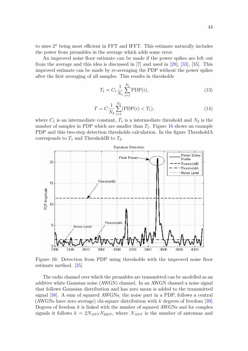
44
to sizes 2n being most efficient in FFT and IFFT. This estimate naturally includesthe power from preambles in the average which adds some error.
An improved noise floor estimate can be made if the power spikes are left outfrom the average and this idea is discussed in [7] and used in [28], [33], [35]. Thisimproved estimate can be made by re-averaging the PDP without the power spikesafter the first averaging of all samples. This results in thresholds
T1 = C11
N1
N1∑i=1
PDP(i), (13)
T = C1
N2
N2∑i=1
(PDP(i) < T1), (14)
where C1 is an intermediate constant, T1 is a intermediate threshold and N2 is thenumber of samples in PDP which are smaller than T1. Figure 16 shows an examplePDP and this two-step detection thresholds calculation. In the figure ThresholdAcorresponds to T1 and ThresholdB to T2.
Figure 16: Detection from PDP using thresholds with the improved noise floorestimate method. [35]
The radio channel over which the preambles are transmitted can be modelled as anadditive white Gaussian noise (AWGN) channel. In an AWGN channel a noise signalthat follows Gaussian distribution and has zero mean is added to the transmittedsignal [38]. A sum of squared AWGNs, the noise part in a PDP, follows a central(AWGNs have zero average) chi-square distribution with k degrees of freedom [39].Degrees of freedom k is linked with the number of squared AWGNs and for complexsignals it follows k = 2NANT NREP , where NANT is the number of antennas and
45
NREP is the number of repetitions that are combined non-coherently [7]. Cumulativedistribution function (CDF) of a chi-square distribution with k degrees of freedom is
F (T ) = 1 − e− kT2
k2 −1∑x=0
1x! (
kT
2 )x, (15)
where T is threshold value [7], [33].The CDF tells the probability that F (T ) gets a value that is T or lower. This
equation is then used to find a value for the intermediate constant C1 such that acertain percentage of the noise is under the constant C1. The intermediate thresh-old T1 is calculated by scaling this constant with the calculated average and thusapproximately the same certain percentage of noise is used in the second averagingcalculation. [33]
As discussed in section 2.4 missed and false detection rates are the most importantmetrics for a PRACH detector. Threshold selection is the most important variablethat is used to adjust these rates. For example [7], [27] set the threshold based on atarget false detection rate using the CDF for AWGN. In [33] only the intermediatethreshold is set using the CDF and the final threshold is set experimentally usingsimulations. A threshold set by simulations could provide better performance becausethere can be other types of noise and interference in addition to AWGN in theradio channel which are difficult or even impossible to take into account in a singlemathematical formula. Optimizing detection thresholds is out of scope of this thesisas the focus is in the PRACH implementation on FPGA.
There are many different ways to use beamforming in PRACH. 5G standards donot specify how beamforming should or could be done but provide enough flexibilityto support different types of beamforming. PRACH typically tries to reuse as muchof the hardware and functionalities implemented for other channels as possible toconserve resources. Hardware available in the system is a key factor in what kind ofbeamforming scheme can be realized for PRACH.
When discussing beamforming in RA there are three interesting points at whichbeamforming can be done. These points are SSB, PRACH, and RAR. Beamformingafter these three first steps of RA is just beamforming of the regular uplink anddownlink traffic which is not interesting from the point of view of this thesis. Atthe three points beamforming can happen both in BTS and UE or only in eitherone. What kind of beamforming is used at each of these points and devices is animportant question when considering beamforming in RA as a decision in one of thepoints can limit what options there are available for the two other points.
The different kinds of beamforming that can be used in RA can be consideredfrom the point of view of the number of simultaneous beams that the system can use.With analog beamforming only a single beam can be used at a time while hybridbeamforming can support as many beams as there are analog signal chains. Digitalbeamforming offers most beams as it is only limited by the number of antennas. Thesystem’s capability to support a certain amount of simultaneous beams at one ofthe three points has a great effect on how the whole beamforming system can beconstructed.
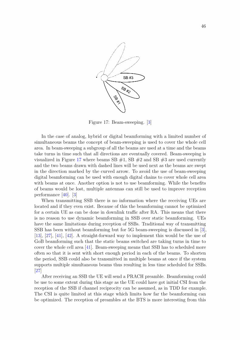
46
Figure 17: Beam-sweeping. [3]
In the case of analog, hybrid or digital beamforming with a limited number ofsimultaneous beams the concept of beam-sweeping is used to cover the whole cellarea. In beam-sweeping a subgroup of all the beams are used at a time and the beamstake turns in time such that all directions are eventually covered. Beam-sweeping isvisualized in Figure 17 where beams SB #1, SB #2 and SB #3 are used currentlyand the two beams drawn with dashed lines will be used next as the beams are sweptin the direction marked by the curved arrow. To avoid the use of beam-sweepingdigital beamforming can be used with enough digital chains to cover whole cell areawith beams at once. Another option is not to use beamforming. While the benefitsof beams would be lost, multiple antennas can still be used to improve receptionperformance [40]. [3]
When transmitting SSB there is no information where the receiving UEs arelocated and if they even exist. Because of this the beamforming cannot be optimizedfor a certain UE as can be done in downlink traffic after RA. This means that thereis no reason to use dynamic beamforming in SSB over static beamforming. UEshave the same limitations during reception of SSBs. Traditional way of transmittingSSB has been without beamforming but for 5G beam-sweeping is discussed in [3],[13], [27], [41], [42]. A straight-forward way to implement this would be the use ofGoB beamforming such that the static beams switched are taking turns in time tocover the whole cell area [41]. Beam-sweeping means that SSB has to scheduled moreoften so that it is sent with short enough period in each of the beams. To shortenthe period, SSB could also be transmitted in multiple beams at once if the systemsupports multiple simultaneous beams thus resulting in less time scheduled for SSBs.[27]
After receiving an SSB the UE will send a PRACH preamble. Beamforming couldbe use to some extent during this stage as the UE could have got initial CSI from thereception of the SSB if channel reciprocity can be assumed, as in TDD for example.The CSI is quite limited at this stage which limits how far the beamforming canbe optimized. The reception of preambles at the BTS is more interesting from this

47
thesis’ point of view. The BTS does not have information about the UEs whichlimits the scale of beamforming that can be done at this step. If beam-sweeping wasused, the SSBs in different beams can request the preamble transmissions at differenttimes. This means that the BTS knows that in a certain preamble reception timewindow UEs that received the matching SSB can transmit their preambles. Due tobeam reciprocity the BTS can use the same beams for preamble reception as wasused for SSB transmission. [3] Beam-sweeping has here the same issue as in SSBtransmission that more time resources have to be scheduled to cover each beam. Itis also an option not to use beamforming or use digital beamforming with enoughparallel beams to receive from all directions at once. For best resource-efficiency thebeamforming in SSB and PRACH should be designed to fit together. For example,if using more parallel beams in PRACH reception that what was used to transmitthe SSB might only have diminishing benefits compared to the amount of resourcesthat are required for processing increased amount of beams.
After receiving a preamble the BTS has some knowledge of the UE which sent it.How much CSI there can be is dependent on how many antennas and beams thereare and how the detector uses these two to gather CSI. In case of beam-sweepingat which time the preamble is received directly maps to the beam or beams fromwhich the UE got the SSB. These information sources can used to beamform RARinto the UE. For example with GoB and beam-steering it is easy to beamform RARusing the same beam that it was received from taking advantage of beam reciprocity.If more CSI can be gathered in PRACH even dynamic beamforming could be usedto construct a more optimized beamforming matrix for a specific UE.
In literature a beam-sweeping system is the most commonly found beamformingscheme that is suggested for PRACH. This combines synchronized beam-sweepingof SSB and PRACH reception with RAR transmission using the same beam as theprevious two. [3], [13], [27], [41], [42]. What kind of beamformer is used in thisbeam-sweeping scheme is not specified further but it would be safe to assume thatGoB or other similar static beamforming is used due to missing CSI in the beginningof RA which was discussed above. A different scheme is presented in [40] in whicha large number of antennas without PRACH reception beamforming are used togather CSI and a novel method is used to group colliding preambles. RAR will bebeamformed using the CSI for the grouped preambles.
In this thesis digital GoB beamforming is used. The system has capability to haveenough simultaneous digital beams to receive in the whole cell simultaneously. Whatis done in SSB and RAR is not specified but these two are out of scope of this thesisin any case as the PRACH is able to receive all directions at once it doesn’t needto be synchronized with SSB like in beam-sweeping. Still, as an example, this kindof PRACH beamforming would fit well together with matching simultaneous GoBbeamforming for SSBs. GoB beamforming with enough beams to detect in the wholecell simultaneously can be considered a special case of GoB with beam-sweeping withonly a single sweep set. This kind of special case is mentioned in the literature, e.g.[3], but no further studies were found on this sort of PRACH beamforming.
48
3.5 Resulting designThis section describes the design of the implementation and provides reasoning whyit is done as it is. This begins by discussing the design goals of resource-efficiencyand scalability and how they can be accounted for in the design. Next, a higher levelview of the design is presented before ending the section with discussion of specificsub-parts of the design.
When creating an FPGA design the resources are naturally provided by theFPGA. To have an resource-efficient end result the design has to be done such thatthe building blocks provided by the FPGA fit well to the design. For example, it isoften better to use IP or hardware blocks provided by the FPGA instead of creating anew block for a certain task even if using the ready blocks causes slight inconveniencewhen fitting it to the rest of the design. In addition to saving resources, using readyblocks can reduce development time and bugs as the block is thoroughly tested bythe FPGA manufacturer. Another way to achieve better resource-efficiency is reusingas much of the sub-parts of the design as possible. If, for example, one slightly largerblock can be used to perform two tasks instead of having own blocks for both of thetasks a lot of resources can be saved.
Scalability can be considered from a few different points of view. One pointof view is scalability during run-time or compile-time. Run-time scalability meanssupporting different configurations with a single bitfile and compile-time scalabilitymeans that bitfiles for different configurations can be created from the same designor with only small changes. Another point of view is scalability as in supportingmultiple parameters for a certain function or scalability as in adding more processingcapacity. Because this implementation shall be resource-efficient and does not need tosupport many different configurations as was discussed in the requirements section itis enough to have only a certain level of run-time scalability for different parametersand some level of readiness for compile-time scalability of processing capacity. Adesign can be make scalable, for example, by using parametrization in the designinstead of hard-coding values and considering which parts could be parallelized suchthat processing capability can be adjusted by varying the amount of parallel blocks.
The PRACH implementation of this thesis does not work alone. There are otherblocks and software on the FPGA to do other processing functions and control ofthe system. Other system parts will provide this implementation with configurationoptions and input data. Also detection results will be given to the rest of the system.All this means that there needs to be interfaces to the rest of the system. Thisimplementation will be provided with IQ input data from a FIFO and configurationsthrough an AXI interface. Detection results will be reported through the same AXIinterface.
Figure 18 shows the block diagram of this implementation. Continuous lines showthe flow of data and dashed lines show the flow of settings or reference sequences.The interfaces to rest of the system are shown on the left side of the block diagram.The following is a short description of the purpose and functionality of each of theblocks in the figure.
• Settings block provides an AXI interface for configuring this PRACH block

49
Figure 18: Block diagram of the implementation.
and reporting the detection results.
• Results bram block stores detection results. This is a Xilinx IP block.
• Reference bram block stores reference sequences. This is a Xilinx IP block.
• Combiner block reads input data from a first-in-first-out (FIFO) buffer, sumsrepetitions, feeds the combined repetitions and reference sequences to thecontroller block, collects the detection results and stores them in results bramfor the settings block.
• Controller block controls and synchronizes the operation of its sub-blocks:
– GoB block does beamforming.– xfft block calculates FFT and IFFT. This is a Xilinx IP block.– Demapper block extracts the preamble bins from the xfft block’s output
frequency band.– Correlator block correlates the input preamble against a given reference
sequence.– Detector block tries to find detections from the correlation output and
measures the power and RTD of the detections.
The previous blocks handle data mostly as streams and advanced eXtensibleinterface (AXI) streams are used between the blocks. This allows for long pipelineand less buffering. Some buffering steps are needed still when the same piece ofdata is used multiple times in the following blocks. These buffering steps are in thecombiner and the bram block of the controller block. The processing and co-operation

50
of the blocks of this PRACH implementation can be described with the followingsteps:
1. Read input and combine repetitions of a single time occasion to a bram bufferin the combiner block.
2. Stream the combined time occasion through GoB, xfft and demapper blocksto bram block. The data is streamed as many times as there are beams. TheGoB block only calculates and outputs a single beam at once.
3. Stream the data to through correlator and xfft blocks to the detector block.The data is streamed as many times as there are different root sequences tocorrelate against. The root sequences are streamed to the correlator block bythe combiner block such that the samples are synchronized with the data fromthe bram block.
4. The detector block processes the data and the combiner block collects thedetection results as they are found from the data. The combiner block writesthe results into the results bram as they arrive from the detector block.
5. After detection is done for the time occasion rest of the design is notified bydriving a result bit high.
The antennas in the system are dual polarized and the antenna signals arecombined after forming the PDPs. In this implementation calculation of PDPsand combining of the polarizations happen in the beginning of the detector block.Everything before detector block has two synchronized data paths for the twopolarizations. Processing the polarizations sequentially would lead to bufferingbefore the detector which would not be a good trade-off because in most PRACHconfigurations there would not be enough processing power to process everything witha single controller block that doesn’t have two duplicated data paths. Duplicateddata paths are also easier to implement from control logic point of view.
A single xfft block is used for both FFT and IFFT because of the unbalancedamount of processing between them. IFFT needs to be calculated number of rootsequences times for each FFT calculation. Data is also buffered after FFT and beforethe IFFTs so it makes sense to do both calculations on a single xfft instance whichcan select between FFT and IFFT. For the cost of a slight waiting period before thefirst IFFT for correlator output can start after the end of FFT and some increase inthe size of the xfft block the design can work with a single xfft block instead of twoand have higher utilization rate of the xfft block.
The implementation in this thesis has two controller blocks which means that twobeams can be processed in parallel. From combiner block’s point of view it feeds thesame combined data to both of the controller blocks. Combiner also has to controlwhich beam indices are given to each of the controller blocks. In the end havingtwo controller blocks means that only half of the time is needed to process a timeoccasions compared to only using a single controller block. The ability to change theamount of controller blocks is used to make the design more scalable for different

51
configurations with different requirements for the amount of processing that has tobe done in a time unit. The number of controller blocks is set such that each timeoccasion can be processed completely before the next time occasion’s repetitionshave been combined thus being ready for rest of the processing. This means that thePRACH implementation can process any number of time occasions in a continuoussequence without getting overloaded. The number of repetitions in a time occasionis the main driver for selecting the number of controller blocks.
When the two data signals arrive at the detector from the xfft block they arefist squared and summed. This results in a single PDP that has both polarizationscombined. The PDP is stored in bram as it arrives. When the PDP is stored thedetector will start doing passes over the data in bram: first two passes are used tocalculate detection thresholds and the third, final, pass is used to make detectionsfrom the data. The detection are output to the combiner block as they are made sono result buffering is done in the detector.
The detector uses the detection scheme of two thresholds which was presented inSection 3.4. The first pass over the data averages all samples which is then multipliedwith a configurable multiplier to get the threshold for the second pass. The secondpass averages the data samples that are under the threshold and the average is thenmultiplied with another configurable multiplier to get the final detection threshold forthe third pass. The third pass will finally do the detecting using the final threshold.The detector will compare the data samples to the threshold in order. When asample that is higher than the threshold a detection is marked. For the duration ofcontinuous over-the-threshold samples the highest sample value will be the reportedpower level. The reported CS and RTD come from the first over-the-threshold sample.A configurable variable was added to filter out the detection from the latter CS ifthe samples are continuously over the threshold on a CS window edge.

52
4 ResultsThis chapter discusses the results of the implementation. The results follow the stepsfrom section 3.1 and Vivado design flow from section 3.2. First, section 4.1 presentsthe Matlab simulator and results from the simulations. Following sections followthe design flow: section 4.2 is about logic simulation and its results, and section4.3 about synthesis and implementation. Results are assessed and topics for futuredevelopment raised in each of the sections.
4.1 Matlab simulationThis section presents the Matlab PRACH simulator which was built as a part of thethesis work. The goal of the simulator is to help in design of the implementation,verify that the design works and finally function as a reference for the verification ofthe VHDL implementation. Simulator was built to be modular and configurable soit can be reused and extended in the future as needed. However, simulations done inthis thesis focus only on a limited configuration which is described in Section 3.3.
The simulation begins by the generating a randomly chosen set of PRACHpreambles. UEs which transmit these preambles are given random directions anddistances in relation to the receiver and the preambles are passed through configurablechannel model. The simulator implements Rayleigh fading and multipath whichallows a configurable number of taps with randomized directions and delays andconfigurable amplitudes. The receiver has a simple antenna model which adds antennadirectionality. Finally noise is added to the combined preamble and multipath signalsbefore they are input into the PRACH receiver.
Figure 19 presents a simplified simulation run to demonstrate how the simulatorworks. Line-of-sight channel is used here with only Rayleigh fading and noise affectingthe preamble transmission. On the left there’s a plot of the eight beams with theeffect of antenna pattern included. On top left corner there’s an UE which sendsa preamble. The UE, BTS and beams are not on scale. On top right there aretables about the preamble transmitted by the UE, raw detection results from thedetector and simple preamble combination result based on the raw results. In the rawresults it can be seen that power in beam 3 is clearly highest and a simple detectioncombination can be done by selecting this raw result as is done in this simulation.Bottom right corner shows a plot of PDP for this specific root sequence and beamwhich had this detection with the most power. As stated earlier in this thesis, thisimplementation will provide data for each beam which preamble was detected withwhich RTD and power. Further analysis and combination of these raw detectionresults are out of scope of this thesis and thus the very simple model is used here. Itcan be noted that the RTD value is a bit off in this example and it could be improvedby adjusting the detection settings, e.g. thresholds, and using more of the beaminformation in detection combining.
The PRACH receiver part of the simulator implements matches the VHDL designwhich was presented in Section 3.5. Differences between the Matlab simulatorand VHDL implementation are that Matlab simulator in based on floating point

53
Figure 19: Results and plots from a Matlab simulation with simplified configuration.
numbers and VHDL implementation on fixed-point numbers. This creates somedifference in outputs which needs to be taken into account when verifying the VHDLimplementation against the Matlab results.
A few sanity tests were run in the simulator to verify that it works acceptably.Error tolerances were taken from TDLC300-100 conformance test defined by 3GPP[43]. Detection and false detection probabilities were within criteria and also averageTA error passed the test. These tests were performed with a single configuration and toparameter optimization was done in search for performance improvements. Parameteroptimization for the detector to, for example, match a certain configuration set andin-depth performance analysis are out of scope of this thesis. Such optimization andanalysis would be possible to do in the created simulator but are not done here tolimit the amount of work.

54
4.2 Logic simulationThis section discusses the logic simulation for the VHDL implementation and itsresults. The aim of this simulation is to verify that the VHDL implementationmatches the design modelled in Matlab. A VHDL testbench is used in the logicsimulation to simulate other parts of a complete FPGA design. This means that thetestbench needs to configure the PRACH block, feed it input data and collect thedetection results like the complete FPGA design would do. Input data is extractedfrom a Matlab simulation run and fed to the PRACH block in addition to matchingconfiguration parameters using the testbench. Detection results collected by thetestbench will then be checked against the results from Matlab simulation. If theresults match, the implementation matches the Matlab model and this verificationstep is considered successful.
Test bench input and reference signals can be exported from arbitrary steps ofthe Matlab simulation which means that testbenches can be built for sub-parts of thePRACH design in addition to the complete design. Some smaller sub-parts of theVHDL implementation were during earlier part of the implementation but most ofthe testing was done using a testbench for the complete design. Intermediate signalsexported from the Matlab simulation proved to be helpful in debugging the VHDLimplementation to check, for example, at which step of the processing a deviationfrom reference was first visible.
Signals exported from Matlab cannot be used in logic simulation as is because theMatlab simulation uses floating point numbers while the VHDL implementation isdone in fixed-point. This means that some conversion is needed in between to matchthe VHDL implementation’s input format: for example truncation and conversion toa format which is readable by the testbench were needed. This means that there issome difference in the logic simulations detection results compared to the Matlabsimulation’s results. For this reason, the detection results were manually compared.
The deviation from the Matlab model detection results was visible in RTD anddetected power but no detections were missed in the used test cases. For RTD,difference of around one sample could be seen in the detections out of the 256samples but usually the result was the same. Detection power results are not directlycomparable between floating point and fixed point but when the truncations of theimplementation were approximated in Matlab the results were close. In theory, therecan be a test case where these differences could cause a missed detection but this wasnot noticed and was considered a non-issue. Adding more accuracy to the VHDLimplementation would increase resource usage and a trade-off needs to be made. Allin all, the VHDL design passed the logic simulation step.
4.3 Synthesis and implementationSynthesis and implementation of the VHDL design results are discussed in thissection. The aim of the discussion is showing that the design works as intended andassessing how well the design goals are met. Synthesis and implementation are thefinal steps which are included in the work of this thesis. What would be left from
55
the design flow is bitstream generation and upload to an FPGA but these steps arenot feasible at this point because this PRACH design is only a single block of thecomplete FPGA design. Furthermore, synthesis and implementation results shouldmatch the result on a real FPGA so there is there would not be much to gain bytesting the design on a real FPGA at this point in the project. Timing analysisresults are shortly discussed first before resource utilization results are presentedand assessed. Only post-implementation results are discussed in this thesis becauseimplementation is executed later than synthesis in the design flow and results arevery similar between the steps.
Table 4: Post-implementation timing analysis resultsSetupWorst negative slack (WNS) 0.076 nsTotal negative slack (TNS) 0.000 nsHoldWorst hold slack (WNS) 0.025 nsTotal hold slack (TNS) 0.000 nsPulse widthWorst pulse width slack (WNS) 0.295 nsTotal pulse width negative slack (TNS) 0.000 ns
Timing analysis results are shown in Table 4. Three types of timing results arereported there: setup, hold and pulse width. Setup time means the time that isrequired for the signal to be stable before a clock edge, hold time means the timethe signal needs to be stable after a clock edge, and pulse width time means thetime signal needs to be stable at high or low pulse. Worst slack results mark theworst timing result found in the design such that a positive number means that therewas the given amount of extra time left before minimum acceptable timing and anegative number means a violation by the given amount. Total slack is the sum ofviolations of a certain type where zero means no violation and a number above zeromeans there were violations. [44] The results in Table 4 show that the implementeddesign meets the timing criteria.
Table 5: Utilization post-implementationUtilization Available Utilization %
LUT 8686 425280 2.04LUTRAM 1243 213600 0.58
BRAM 32 1080 2.96DSP 196 4272 4.59
Post-implementation utilization results are listed in Table 5 in relation to theavailable resources on the FPGA and in Table 6 per resource type and block. Table 7and Table 8 show more detailed results for the controller blocks divided per resourcetype and sub-block. As discussed in Section 3.5, two controller blocks are used in this

56
Table 6: Utilization post-implementationCLB LUT logic LUTRAM CARRY8 BRAM DSP
Total 2053 7443 1243 414 32 196bram ref 8 39 0 0 2.5 0bram res 0 0 0 0 0.5 0combiner 287 1125 18 2 15 4
controller 0 973 3022 621 203 7 96controller 1 978 3033 603 203 7 96
settings 70 230 1 6 0 0
thesis because they provide enough processing capacity for the used configuration.If the number of controller blocks would be changed the resource usage in blocksother than controller would stay close to the same as it is now and resources used bycontroller blocks would change in synchronization with the number of such blocks.
Table 7: Controller 0 utilization post-implementationCLB LUT logic LUTRAM CARRY8 BRAM DSP
bram 0 0 0 0 1 0correlator 82 92 42 0 0 6demapper 20 52 0 0 0 0detector 102 448 26 25 0.5 8
gob 297 160 249 12 0 64xfft 529 2187 284 159 5.5 18
Table 8: Controller 1 utilization post-implementationCLB LUT logic LUTRAM CARRY8 BRAM DSP
bram 0 0 0 0 1 0correlator 81 94 42 0 0 6demapper 30 52 0 0 0 0detector 101 476 26 28 0.5 8
gob 321 161 250 12 0 64xfft 552 2183 284 159 5.5 18
Some analysis can be made from the utilization results: DSPs are the most usedresource type when comparing with the available resources and almost all of theDSPs are used in GoB blocks. DSP usage could be limited by changing at leastsome of the calculations in the design to use generic logic blocks instead of DSPs.Also redesigning GoB block for less parallel processing and making it reuse the fewerDSPs in a sequential manner could help limit the amount of needed DSPs but thiswould increase the time needed for processing in the GoB block which might causeissues in the overall design. Feasibility of such optimization would depend greatlyon which configuration options need to be supported. Removing support for more

57
demanding configurations could relax the required speed of processing per beam ortime occasion allowing more time to be used in GoB block. Design that was done inthis thesis was made so that even more demanding configurations would work.
Another block with high resource usage is xfft. This block is provided by Xilinxlibraries and it has support for some configuration options. Configuration for xfft wasselected so that it supports, for example, only the minimum required size of DFT.Some resource saving might be possible by studying other DFT implementations orcreating a new implementation to match this very use case. BRAM usage is highestin combiner block because the input signal needs to be buffered there. ReducingBRAM usage notably would be difficult except that LUTs could be used as a memoryinstead of BRAM but that could be a very inefficient trade-off. During integration ofthe PRACH block to the complete design results BRAM could be optimized away iffurther result handling is made so that it could consume results provided by detectorblock immediately.
The overall resource usage shown in Table 5 is fairly small, only a few percentageof the overall available resources, indicates that the implementation achieved thedesign goal of small resource usage quite well. It should be noted that this PRACHblock is only a small part of the full FPGA design. Some optimizations could bepossible to reduce the resource usage but such changes might make the design harderto adapt for different configurations mostly due to the processing taking more time.In a worst case, the slowdown would be large enough that adding more controllerblocks will be required which would negate the gains from optimizing the design. Allin all, based on the available simulation, synthesis and implementation results theimplemented design fulfils its goals well enough to be acceptable. More evaluationshould be done as the whole project and the integration of this PRACH block intothe complete FPGA design progresses.

58
5 Summary and conclusionsThe aim of this thesis was to design and implement 5G-compliant PRACH on FPGA.This thesis was done as a part of a larger research radio project. Beamforming isone of the main focuses in this project and thus GoB beamforming was added tothe PRACH implementation in this thesis. Small resource-usage, configurability andscalability were important goals for the implementation.
Chapter 2 presented theoretical background for this thesis. OFDM as the basisof waveform for 5G and the structure of PRACH preambles were presented basedon 3GPP’s 5G specifications. PRACH preambles are based on ZC sequences withvarying root sequence number and cyclic shift. Zero autocorrelation and limitedcorrelation between root sequences features of ZC mean that they are very suitablefor use in PRACH. A PRACH device in BTS first extracts the preamble sequence andthen correlates it against a reference sequence. Reference sequences are ZC sequenceswith different root sequence numbers. 5G specifies that there should be 64 preambleoptions in a cell and one or more preambles can be constructed from a single ZCroot sequence with the use of cyclic shifts. Use of cyclic shifts is preferred over moreroot sequences because it means less reference sequences and thus correlations in thedetection. After correlation is calculated, correlation spikes are searched from theresult. These spikes mark detected preambles. Chapter 1 also discussed beamformingand used GoB as an example of static beamforming.
Chapter 3 focused on the PRACH implementation specific to this thesis. TheFPGA used for the implementation is Xilinx UltraScale+ XCZU21DR and XilinxVivado tools and design flow were used. Requirements for the implementation werediscussed next. A subset of options that is required in this implementation wasdefined from the many options given for PRACH in 5G specification. One of themain restrictions is that only short PRACH is supported. While the supportedconfiguration set was still quite large, only one configuration set was fully tested inthis thesis to limit the amount of work. The project that this thesis is a part of alsofocuses firstly on a specific configuration so this effort saving was acceptable for thisthesis. This chapter also contains literature study of existing PRACH designs anddiscussion about the final design which was done in this thesis.
Different kinds of sources in literature for PRACH are the standards, papersthat suggest different solutions for standardisation and standard-compatible studieswhich study for example PRACH detectors to achieve more performance. The mainfindings in the literature study were that typically PRACH implementations followthe same basic structure: DFT, demapping, correlation, IDFT and detection. Thisis because demapping and correlation are easier in frequency domain and detectionin time domain. Differences were found in if a large DFT is used or if filtering isadded before a smaller DFT but this didn’t consider this thesis because the systemwas specified such that this PRACH implementation will be given an already filteredsubset of subcarriers.
GoB beamforming was also discussed in the literature and most of it was ofbeam sweeping type. In beam sweeping multiple beams take turns at differenttimes. Both SSB broadcasting and PRACH detection are swept so that preamble

59
detection is focused on the same beam which was used for a certain SSB. TheGoB in this implementation is digital and supports detection in all beam directionssimultaneously which means that switching beams in time is not needed. This sortof solution was mentioned in the literature but not discussed much further.
The resulting PRACH design was then presented. A lot of care was taken duringthe design to meet the goals of small resource usage, configurability and scalability.The PRACH processing was encapsulated into its own sub-block and the amountof those can be changed with parameters in VHDL. This is important in makingthe design scalable and it allows optimizing the resource usage per the neededconfiguration for a certain use case. Another design choice was using a single xfft IPblock by Xilinx to implement both the DFT in IDFT. This increases the utilisation ofthe xfft block so the resource is used more efficiently from the design size perspective.The detector follows mostly the typical structure that was seen in literature study.
Chapter 4 discussed Matlab simulator and simulations which were used as ahelp and verification when creating the above PRACH design, and synthesis andimplementation runs for the VHDL implementation. The Matlab simulator was usedto verify that the PRACH design works acceptably and detection performance iswithin the limits of 3GPP’s TDLC300-100 conformance test. No further parameteroptimization of performance study was done in this thesis because the focus is onthe implementation work.
After the VHDL implementation was done it was verified against the Matlabsimulator. This was done to check that no errors were done in the VHDL. AVHDL testbench was used to configure the PRACH implementation, insert dataexported from the simulations and gather the detection results. Results were thencompared in Matlab against the results from the simulation. Slight difference innumber values was observed because floating point numbers were used in Matlabwhile fixed point numbers with a varying degree of truncation were used in VHDLbut this did not affect which preambles were detected. This verification showed thatthe implementation matched the simulator.
Synthesis and implementation runs for the VHDL implementation passed withoutissues and no violations were seen. This means that the implementation is consideredworking and done. Further verification should be done when the implementationis integrated into the full FPGA design but that is out of the scope of this thesis.Resource usage was analyzed from the utilization implementation run’s results. Itwas noticed that the resource usage was a few percent of the total resources availableon the FPGA and the top usage was in DSP blocks which consumed 4.59 percent ofthe total DSP resources. Such a small usage was a good result because PRACH isonly a small part of the complete design and not in the focus the whole project’sgoals. GoB and xfft blocks were the ones with most resource usage. Some furtherdevelopment might be possible to limit resource usage in those but the assumptionis that there are no easy gains to be achieved. All in all, the implementation isconsidered to fulfil the criteria of small resource usage, configurability and scalability.
60
References[1] ITU, “IMT traffic estimates for the years 2020 to 2030”, M.2370-0, Jul. 2015,
p. 51. [Online]. Available: https://www.itu.int/dms_pub/itu-r/opb/rep/R-REP-M.2370-2015-PDF-E.pdf (visited on 01/29/2019).
[2] ——, “IMT vision – framework and overall objectives of the future developmentof IMT for 2020 and beyond”, M.2083-0, Sep. 2015, p. 21. [Online]. Available:https://www.itu.int/dms_pubrec/itu- r/rec/m/R- REC- M.2083- 0-201509-I!!PDF-E.pdf (visited on 01/30/2019).
[3] E. Dahlman, S. Parkvall, and J. Sköld, 5G NR: The Next Generation WirelessAccess Technology. London: Academic Press, 2018, 441 pp., isbn: 978-0-12-814323-0.
[4] P. S. R. Diniz, W. A. Martins, and M. V. S. Lima, Block transceivers: OFDMand beyond. S.l.: Morgan & Claypool, 2012, OCLC: 804676341, isbn: 978-1-60845-830-1 978-1-60845-829-5.
[5] 3GPP, “NR; Physical channels and modulation”, 3rd Generation PartnershipProject (3GPP), Technical Specification (TS) 38.211, Jan. 2019, Version 15.4.0.[Online]. Available: http://www.3gpp.org/DynaReport/38211.htm.
[6] H. G. Myung, J. Lim, and D. J. Goodman, “Single carrier FDMA for uplinkwireless transmission”, IEEE Vehicular Technology Magazine, vol. 1, no. 3,pp. 30–38, Sep. 2006, issn: 1556-6072. doi: 10.1109/MVT.2006.307304.
[7] S. Sesia, I. Toufik, and M. Baker, LTE - The UMTS Long Term Evolution:From Theory to Practice, 2nd ed. Chippenham, United Kingdom: JohnWiley & Sons Ltd, 2011, isbn: 978-0-470-97851-1. [Online]. Available: http:/ / ebookcentral . proquest . com / lib / aalto - ebooks / detail . action ?docID=693278 (visited on 02/01/2019).
[8] R. Pitaval, B. M. Popovic, F. Berggren, and P. Wang, “Overcoming 5g PRACHcapacity shortfall by combining zadoff-chu and m-sequences”, in 2018 IEEEInternational Conference on Communications (ICC), May 2018, pp. 1–6. doi:10.1109/ICC.2018.8422146.
[9] Q. H. Spencer, A. L. Swindlehurst, and M. Haardt, “Zero-forcing methods fordownlink spatial multiplexing in multiuser MIMO channels”, IEEE Transactionson Signal Processing, vol. 52, no. 2, pp. 461–471, Feb. 2004, issn: 1053-587X.doi: 10.1109/TSP.2003.821107.
[10] P. Marsch, Ö. Bulakçı, O. Queseth, and M. Boldi, Eds., 5G System Design:Architectural and Functional Considerations and Long Term Research, Chich-ester, UK: John Wiley & Sons, Ltd, Apr. 11, 2018, isbn: 978-1-119-42514-4978-1-119-42512-0. doi: 10.1002/9781119425144. [Online]. Available: http://doi.wiley.com/10.1002/9781119425144 (visited on 04/17/2019).
61
[11] Benson, Keith. (). Phased array beamforming ICs simplify antenna design,[Online]. Available: https://www.analog.com/en/analog- dialogue/articles/phased-array-beamforming-ics-simplify-antenna-design.html (visited on 06/08/2020).
[12] J. Flordelis, F. Rusek, F. Tufvesson, E. G. Larsson, and O. Edfors, “Mas-sive MIMO performance - TDD versus FDD: What do measurements say?”,arXiv:1704.00623 [cs, math], Apr. 3, 2017. arXiv: 1704.00623. [Online].Available: http://arxiv.org/abs/1704.00623 (visited on 04/29/2019).
[13] C. Jeong, J. Park, and H. Yu, “Random access in millimeter-wave beamformingcellular networks: Issues and approaches”, IEEE Communications Magazine,vol. 53, no. 1, pp. 180–185, Jan. 2015, issn: 0163-6804. doi: 10.1109/MCOM.2015.7010532.
[14] 3GPP, “NG-RAN; Architecture description”, 3rd Generation PartnershipProject (3GPP), Technical Specification (TS) 38.401, Jan. 2019, Version 15.3.0.[Online]. Available: http://www.3gpp.org/DynaReport/38401.htm.
[15] “Transport network support of IMT-2020/5g”, ITU, GSTR-TN5G. [Online].Available: https://www.itu.int/dms_pub/itu-t/opb/tut/T-TUT-HOME-2018-PDF-E.pdf (visited on 03/26/2020).
[16] Xilinx, “UltraScale architecture configurable logic block user guide (UG574)”,p. 58, 2017. [Online]. Available: https://www.xilinx.com/support/documentation/user_guides/ug574-ultrascale-clb.pdf.
[17] ——, “UltraScale architecture DSP slice user guide (UG579)”, p. 75, 2018.[Online]. Available: https://www.xilinx.com/support/documentation/user_guides/ug579-ultrascale-dsp.pdf.
[18] ——, “UltraScale architecture memory resources user guide”, p. 137, 2019.[Online]. Available: https://www.xilinx.com/support/documentation/user_guides/ug573-ultrascale-memory-resources.pdf.
[19] ——, “Zynq UltraScale+ device technical reference manual”, p. 1178, 2019.[Online]. Available: https://www.xilinx.com/support/documentation/user_guides/ug1085-zynq-ultrascale-trm.pdf.
[20] ——, “UltraScale architecture and product data sheet: Overview (DS890)”,p. 46, 2018. [Online]. Available: https://www.xilinx.com/support/documentation/data_sheets/ds890-ultrascale-overview.pdf.
[21] ——, “Vivado design suite user guide: Design flows overview (UG892)”, p. 106,[Online]. Available: https://www.xilinx.com/support/documentation/sw_manuals/xilinx2020_2/ug892-vivado-design-flows-overview.pdf.
[22] H. Amano, Ed., Principles and Structures of FPGAs, Singapore: SpringerSingapore, 2018, isbn: 9789811308239 9789811308246. doi: 10.1007/978-981-13-0824-6. [Online]. Available: http://link.springer.com/10.1007/978-981-13-0824-6 (visited on 08/19/2020).

62
[23] ——, “Vivado design suite user guide: Logic simulation (UG900)”, p. 267, 2018.[Online]. Available: https://www.xilinx.com/support/documentation/sw_manuals/xilinx2018_3/ug900-vivado-logic-simulation.pdf.
[24] ——, “Vivado design suite user guide: Programming and debugging (UG908)”,p. 394, 2019. [Online]. Available: https://www.xilinx.com/support/documentation/sw_manuals/xilinx2019_2/ug908-vivado-programming-debugging.pdf.
[25] ——, “Vivado design suite user guide: Implementation (UG904)”, p. 188, 2016.[Online]. Available: https://www.xilinx.com/support/documentation/sw_manuals/xilinx2016_2/ug904-vivado-implementation.pdf.
[26] ——, “Vivado design suite tutorial: Design flows overview (UG888)”, p. 47,2017. [Online]. Available: https://www.xilinx.com/support/documentation/sw _ manuals / xilinx2017 _ 1 / ug888 - vivado - design - flows - overview -tutorial.pdf.
[27] H. Sahlin, S. Parkvall, M. Frenne, and P. Nauclér, “Random access preambleformat for systems with many antennas”, in 2014 IEEE Globecom Workshops(GC Wkshps), Dec. 2014, pp. 875–880. doi: 10 . 1109 / GLOCOMW . 2014 .7063543.
[28] P. Li and B. Wu, “An effective approach to detect random access preamble inLTE systems in low SNR”, Procedia Engineering, CEIS 2011, vol. 15, pp. 2339–2343, Jan. 1, 2011, issn: 1877-7058. doi: 10.1016/j.proeng.2011.08.438.[Online]. Available: http://www.sciencedirect.com/science/article/pii/S1877705811019394 (visited on 03/13/2019).
[29] Li, Tianhao, Wang, Wenbo, and Peng, Tao, “An improved preamble detectionmethod for LTE PRACH in high-speed railway scenario”, in 2015 10th Interna-tional Conference on Communications and Networking in China (ChinaCom),Aug. 2015, pp. 544–549. doi: 10.1109/CHINACOM.2015.7497998.
[30] A. Freire-Irigoyen, R. Torrea-Duran, S. Pollin, E. Lopez, and L. V. d. Perre,“Energy efficient PRACH detector algorithm in SDR for LTE femtocells”, in2011 18th IEEE Symposium on Communications and Vehicular Technology inthe Benelux (SCVT), Nov. 2011, pp. 1–5. doi: 10.1109/SCVT.2011.6101311.
[31] T. Wang, H. Guo, and L. Ruan, “Low complexity random access detection for5g millimeter wave communications”, in 2018 IEEE 87th Vehicular TechnologyConference (VTC Spring), Jun. 2018, pp. 1–5. doi: 10.1109/VTCSpring.2018.8417524.
[32] F. Pereira de Figueiredo, F. Cardoso, J. Bianco Filho, K. Lenzi, and F. Lira,“Multi-stage based cross-correlation peak detection for LTE random accesspreambles”, Revista Telecomunicacoes, vol. 15, Oct. 16, 2013.
[33] Törmälehto, Jukka, “Random access channel preamble detection in 3g longterm evolution”, Master’s thesis, University of Oulu, Department of Electricaland Communications Engineering, Oulu, 2007.
63
[34] T. A. Pham and B. T. Le, “A proposed preamble detection algorithm for5g-PRACH”, in 2019 International Conference on Advanced Technologies forCommunications (ATC), Hanoi, Vietnam: IEEE, Oct. 2019, pp. 210–214,isbn: 978-1-72812-392-9. doi: 10 . 1109 / ATC . 2019 . 8924502. [Online].Available: https://ieeexplore.ieee.org/document/8924502/ (visited on05/19/2020).
[35] Yanchao Hu, Juan Han, Shan Tang, Huajie Gao, Yongtao Su, and JinglinShi, “A method of PRACH detection threshold setting in LTE TDD femtocellsystem”, in 7th International Conference on Communications and Networking inChina, Kun Ming: IEEE, Aug. 2012, pp. 408–413, isbn: 978-1-4673-2699-5 978-1-4673-2698-8 978-1-4673-2697-1. doi: 10.1109/ChinaCom.2012.6417517.[Online]. Available: http://ieeexplore.ieee.org/document/6417517/(visited on 06/10/2020).
[36] F. A. P. de Figueiredo, F. S. Mathilde, F. A. C. M. Cardoso, R. M. Vilela,and J. P. Miranda, “Efficient frequency domain zadoff-chu generator withapplication to LTE and LTE-a systems”, in 2014 International Telecommuni-cations Symposium (ITS), Sao Paulo, Brazil: IEEE, Aug. 2014, pp. 1–5, isbn:978-1-4799-3743-1. doi: 10.1109/ITS.2014.6947990. [Online]. Available:http://ieeexplore.ieee.org/document/6947990/ (visited on 01/28/2019).
[37] M. M. Mansour, “Optimized architecture for computing zadoff-chu sequenceswith application to LTE”, in GLOBECOM 2009 - 2009 IEEE Global Telecom-munications Conference, Nov. 2009, pp. 1–6. doi: 10.1109/GLOCOM.2009.5426248.
[38] B. Honary, F. Ali, and M. Darnell, “Information capacity of additive whitegaussian noise channel with practical constraints”, Speech and Vision IEEProceedings I - Communications, vol. 137, no. 5, pp. 295–301, Oct. 1990, issn:0956-3776. doi: 10.1049/ip-i-2.1990.0041.
[39] J. G. Proakis, Digital communications, 4th ed, ser. McGraw-Hill series inelectrical and computer engineering. Boston: McGraw-Hill, 2000, 1002 pp.,isbn: 978-0-07-232111-1.
[40] S. Mukherjee, A. K. Sinha, and S. K. Mohammed, “Timing advance estimationand beamforming of random access response in crowded TDD massive MIMOsystems”, IEEE Transactions on Communications, pp. 1–1, 2019, issn: 0090-6778. doi: 10.1109/TCOMM.2019.2900242.
[41] J. Tan, M. Cudak, T. Thomas, R. Ratasuk, F. Vook, A. Ghosh, and A.Talukdar, “Random access channel with a grid of beams for communicationsystems”, U.S. Patent 20160119958A1, Apr. 28, 2016. [Online]. Available:https://patents.google.com/patent/US20160119958A1/en (visited on04/29/2019).
[42] S. Lien, S. Shieh, Y. Huang, B. Su, Y. Hsu, and H. Wei, “5g new radio:Waveform, frame structure, multiple access, and initial access”, IEEE Commu-nications Magazine, vol. 55, no. 6, pp. 64–71, Jun. 2017, issn: 0163-6804. doi:10.1109/MCOM.2017.1601107.

64
[43] 3GPP, “NR; Base Station (BS) conformance testing Part 2: Radiated con-formance testing”, 3rd Generation Partnership Project (3GPP), TechnicalSpecification (TS) 38.141-2, Jan. 2019, Version 15.0.0. [Online]. Available:http://www.3gpp.org/DynaReport/38141-2.htm.
[44] Xilinx, “Vivado design suite user guide: Design analysis and closure tech-niques (UG906)”, p. 332, 2019. [Online]. Available: https://www.xilinx.com/support/documentation/sw_manuals/xilinx2019_2/ug906-vivado-design-analysis.pdf.