physical interconnection requirements habib youssef, ph.d [email protected] department of...
TRANSCRIPT

Physical Interconnection Requirements
Habib Youssef, Ph.D
Department of Computer Engineering
King Fahd University of Petroleum and Minerals
Dhahran, Saudi Arabia
COMPUTER NETWORKS
Communication Requirements
Essential issues in a data communication system:Physical Interface Connectors :
Shape, size, no. of pins, serial/parallel.Protocols
Rules of communication at various layers.
Codes/formats.

Communication Requirements (Cont.)
Basic concept behind a protocol is Handshaking (hardware) Syntax, semantics, and procedure rules
(software)

Communication Requirements (Cont.)
The protocol allows each party to show the other end that it has something to send, it is ready to accept messages, a message has been received, and the reception has been successful.
If any of the communication steps fails, the protocol should indicate this, and each party follows a predefined set of rules too handle the exception.
Purpose of Physical Layer Connections
The basic purpose of the OSI Physical Layer is»To adapt the digital signals to allow them to be communicated across the physical medium.
Examples include»Convert digital signals to tones for communications across a voice grade telephone circuit.
»Convert digital signals to light (on/off) for communications across a fiber-optic circuit.
Purpose of Physical Layer Connections (Cont.)
The communications circuit may need to be» Established (initially)» Controlled or maintained» Released when no longer needed
The Physical Layer may also be responsible for sharing (multiplexing) the communications circuit.
Inter- vs. Intracomputer Communications
Data communications characteristics differ from those within a computer system.» Bit serial transmission» Handling control information (inband control)» Higher error rate (need error detectioon and
correction) These issues are discussed on the
following slides

Inter- vs. Intracomputer Communications(Cont.)
Host
Internal Bus
External Communications Line
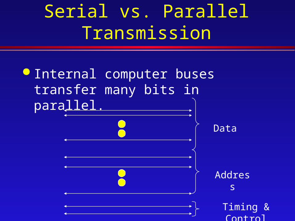
Serial vs. Parallel Transmission
Internal computer buses transfer many bits in parallel.
Data
Address
Timing & Control
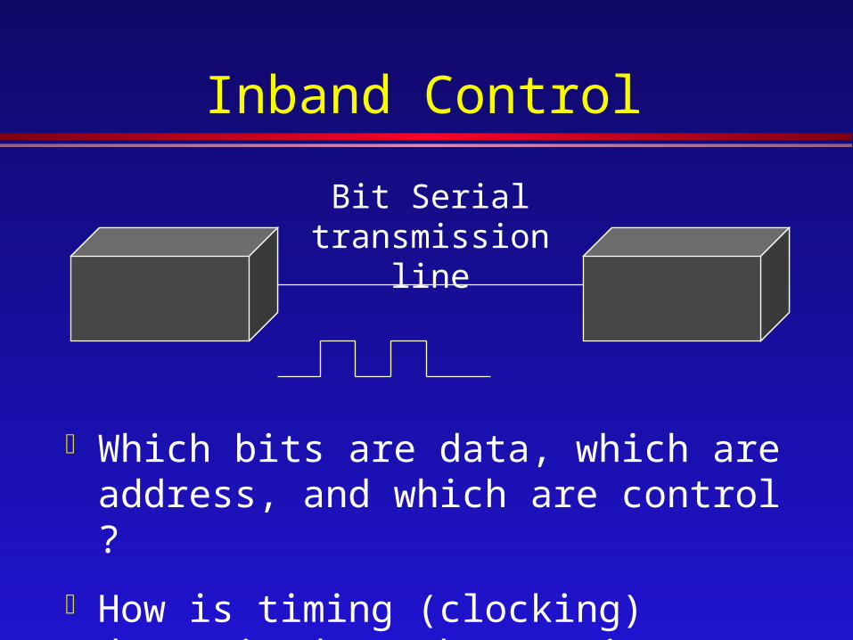
Inband Control
Bit Serial transmission line
Which bits are data, which are address, and which are control ?
How is timing (clocking) determined at the receiver?
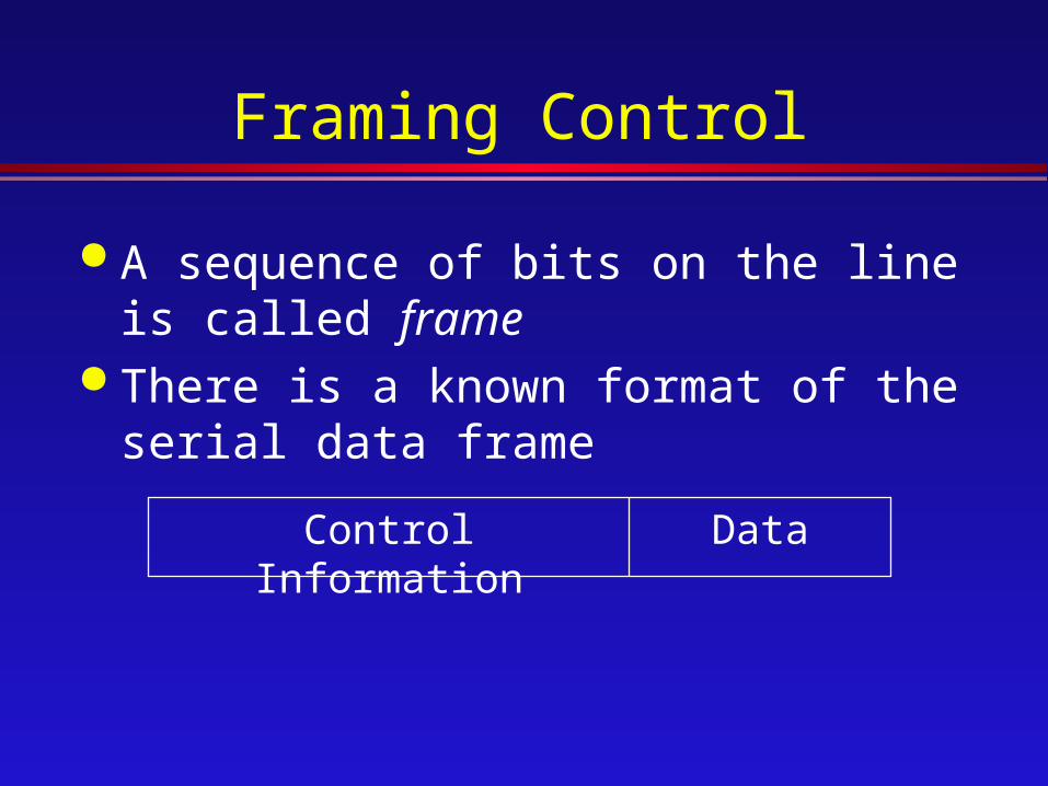
Framing Control
A sequence of bits on the line is called frame
There is a known format of the serial data frame
Control Information Data
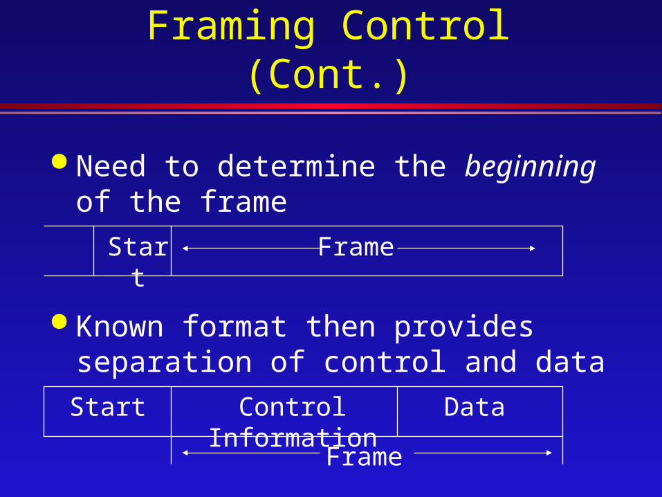
Framing Control (Cont.)
Need to determine the beginning of the frame
Start Frame
Known format then provides separation of control and data
Start Control Information Data
Frame
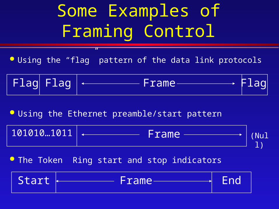
Some Examples of Framing Control
Using the “flag” pattern of the data link protocols
Flag FrameFlag Flag
Using the Ethernet preamble/start pattern
Frame101010…1011 (Null)
The Token Ring start and stop indicators
Start EndFrame
Error Rates
The physically lines have inherently different error properties.
The average error rate: the fraction of bits delivered with errors; e.g.,one in 105 for telephone channels» For lengthy transmissions, this error rate is
often unsatisfactory» It must be improved by higher level protocol
mechanisms

Error Rates (Cont.)
Some media may have error rates as low as one in 1014 » May be adequate for many purposes; e.g.,
digitized images» Still typically have higher level protocol
recovery mechanisms
Switched Voice-Grade Telephone Channels
Direct-dial analog telephone channels» Dial-up modem use
Normal voice line» Limited to about 3000 Hz bandwidth
The local loop is a two-wire circuit» To the central office(exchange)
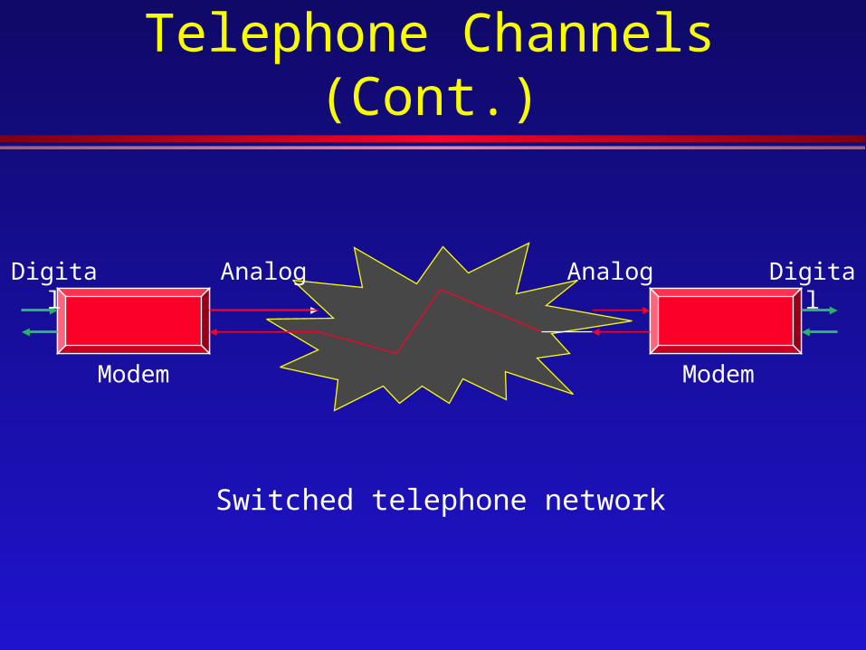
Switched Voice-Grade Telephone Channels
(Cont.)
Modem Modem
Analog AnalogDigital Digital
Switched telephone network

Switched Voice-Grade Telephone Channels
(Cont.)
PSTN
PAD
Home PC

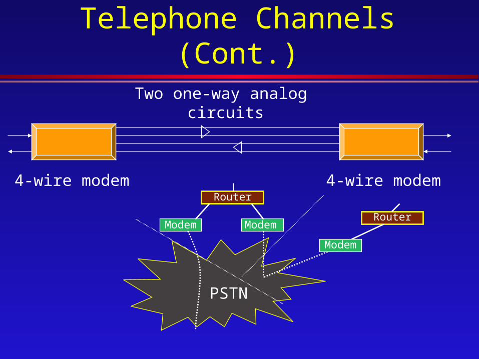
Leased Voice-Grade Telephone Channels
Leased (dedicated) analog telephone channels» Sometimes called “conditioned” lines
Often used for 19.2-kbit/s transmission Fixed monthly cost, independent of
usage
Leased Voice-Grade Telephone Channels
(Cont.)
4-wire modem4-wire modem
Two one-way analog circuits
Router
Router
PSTN
Modem
ModemModem
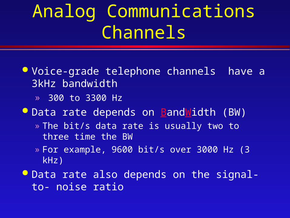
Analog Communications Channels
Voice-grade telephone channels have a 3kHz bandwidth» 300 to 3300 Hz
Data rate depends on BandWidth (BW)» The bit/s data rate is usually two to three time the
BW
» For example, 9600 bit/s over 3000 Hz (3 kHz) Data rate also depends on the signal-to-
noise ratio

Analog Communications Channels (Cont.)
300 3300
3 kH bandwidth
Pass
100%
Frequency, Hz
kHz=1000 hertz

Digitized Voice Channels
Digitized voice channels can also be used for digital data
Analog voice signals are digitized
Time
Samples 8000 samples per second56 kbit/s
or 64 kbit/s
Send digitized value of each sample
7 or 8 bits per sample
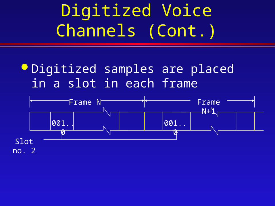
Digitized Voice Channels (Cont.)
Digitized samples are placed in a slot in each frame
001..0
Frame N Frame N+1
001..0
Slot no. 2

Digitized Voice Channels (Cont.)
The frames for digitized voice have two different forms :T1 has 24 slots per frame
» 24 slots at 56 kbit/s (or 64 kbit/s)» A total of 1.544 Mbit/s
“E1” or CEPT» 32 slots at 64 kbit/s» 2.048 Mbit/s

Digital Telephone Channels
Digital (instead of analog) telephone communications channels are also available
» 56 or 64 kbit/s channels (or a multiple)» 1.544 Mbit/s (US, Canada, and Japan) or
2.048Mbit/s (Europe) channels

Digital Telephone Channels (Cont.)
Instead of modem, Data Service Unit / Channel Service Unit (DSU/CSU) adapter devices are needed.» The DSU adapts the digital signal (transmit
and receive voltages and timing)» The CSU normalizes voltage levels,
provides maintenance capabilities, and protect the public network.

Digital Telephone Channels (Cont.)
DSU/CSU DSU/CSU
DSU/CSU DSU/CSU
Inter-central office/exchange links
(high data rates)
Central office or exchange
Central office or exchange

Reason for Going Digital Computer data are inherently digital
» Adapt more easily to digital transmission
Easier to multiplex» Time Division Multiplexing (TDM)
Easier to switch Better error rate
» Noise is not cumulative, since repeaters can reject most induced noise
Repeater
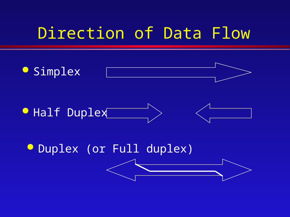
Direction of Data Flow
Simplex
Half Duplex
Duplex (or Full duplex)
ANALOG AND DIGITAL PHYSICAL INTERFACES
COMPUTER NETWORK
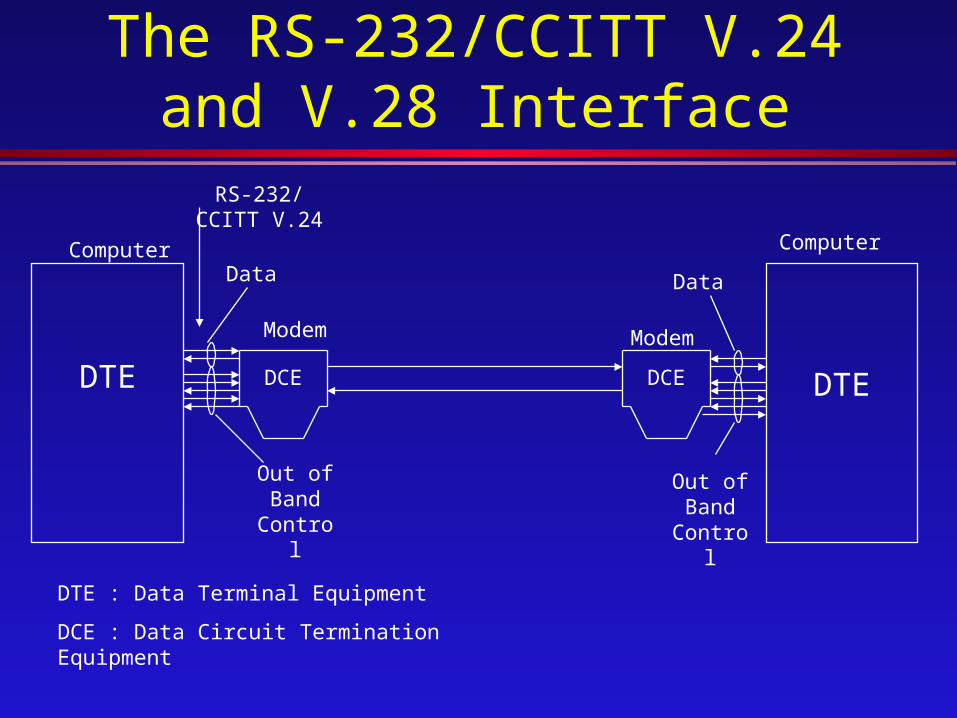
The RS-232/CCITT V.24 and V.28 Interface
Data
Out of Band
Control
Computer
DTEDCE
Modem
Data
Out of Band
Control
DCEDTE
Computer
Modem
RS-232/CCITT V.24
DTE : Data Terminal Equipment
DCE : Data Circuit Termination Equipment
Data processing (DTE) to modem (DCE) interface
The CCITT V.24 Recommendation defines the interchange circuits» V.28 defines the electrical characteristics
The RS-232/CCITT V.24 and V.28 Interface (Cont.)
In EIA, known as RS-232-C (the third [-C] version of RS-232)» More recent version of RS-232-D (now EIA-
232-D)» Sometimes TIA-232-D
(Telecommunications Industry Association)
The RS-232/CCITT V.24 and V.28 Interface (Cont.)
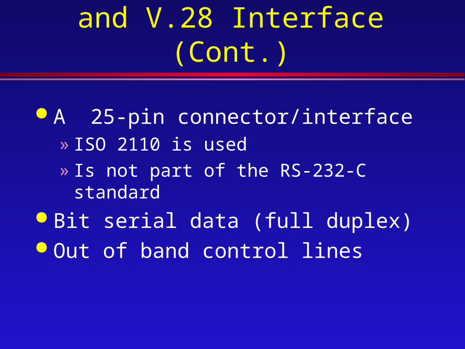
A 25-pin connector/interface» ISO 2110 is used» Is not part of the RS-232-C standard
Bit serial data (full duplex) Out of band control lines
The RS-232/CCITT V.24 and V.28 Interface (Cont.)

The RS-232/CCITT V.24 and V.28 With Null
Modems
2
3
4
5
6
8
20
7
2
3
4
5
6
8
20
7
Data
Data
Req to Send
Clear to Send
Data Set Ready
Signal Detect
Data Terminal Ready
Req to SendClear to Send
Data Set Ready
Signal Detect
Data Terminal Ready
Data
Data
Signal Ground
Note : There are many variations to Null Modem Cross Connection
DCEDTE Null Modem

Pin Assignments for V.24/EIA-232
14 15 2116 2017 1918 22 23 24 25
1 2 3 4 5 6 7 8 9 10 11 12 13
Shield
Tx Data
Rx Data
Reg to Send
Clear to Send
DCE Ready
GND
Carrier Detect
Reserved for testing
Reserved for testing
Unassigned
Secn. Recv. Line Signal
Detector
Secn. CTS
Secondary Tx Data
Transmitter signal element
timing
Secondary received data
Transmitter signal element
timing
Local Loopback
Secondary RTS
DTE Ready
Remote Loopback
Ring Indicator
Data Signal Rate Select
Transmit signal element
timing
Test Mode
RS-232/CCITT V.24 & V.28 Related Products
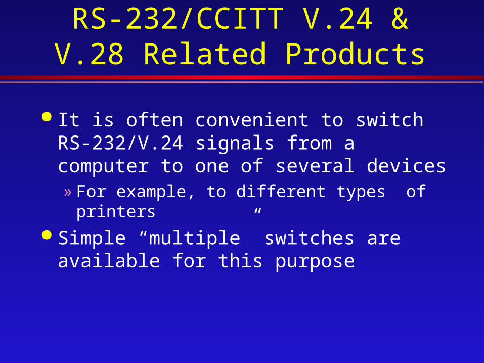
It is often convenient to switch RS-232/V.24 signals from a computer to one of several devices» For example, to different types of printers
Simple “multiple” switches are available for this purpose
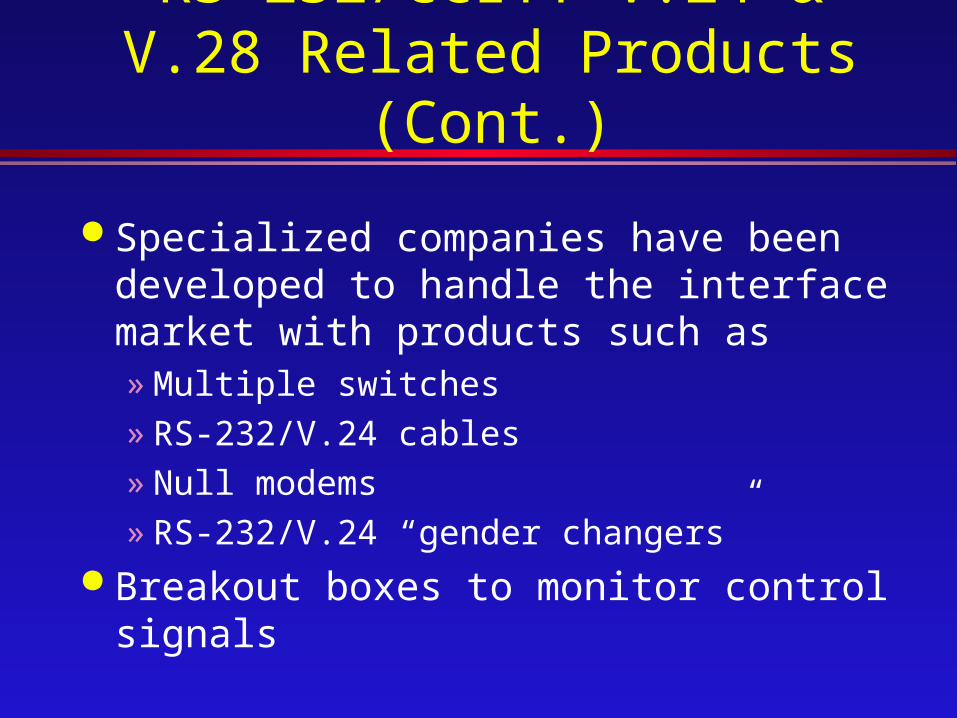
Specialized companies have been developed to handle the interface market with products such as» Multiple switches» RS-232/V.24 cables» Null modems» RS-232/V.24 “gender changers”
Breakout boxes to monitor control signals
RS-232/CCITT V.24 & V.28 Related Products (Cont.)
Limitations of RS-232/V.28
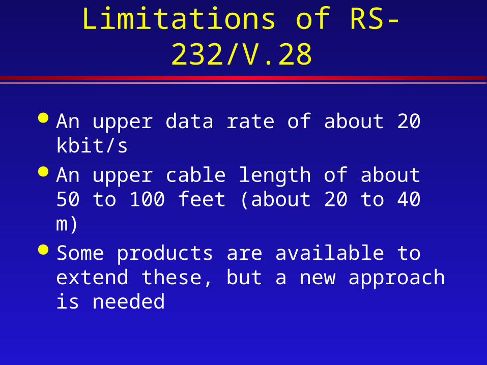
An upper data rate of about 20 kbit/s An upper cable length of about 50 to 100
feet (about 20 to 40 m) Some products are available to extend
these, but a new approach is needed

The Evolution of RS-232-C
RS-232-C
EIA-232-D (1987)
• Unbalanced circuits
RS-530 (1987)
•Balanced Circuits
V.35
•Balanced Circuits
RS-449 signals
RS-422/423 electrical (1977)
RS-442 balanced circuits
RS-443 unbalanced circuits

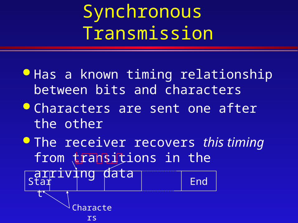
Synchronous Transmission
Has a known timing relationship between bits and characters
Characters are sent one after the other The receiver recovers this timing from
transitions in the arriving data
Start End
1
0
Characters

V.24/EIA-232 dial-up operation
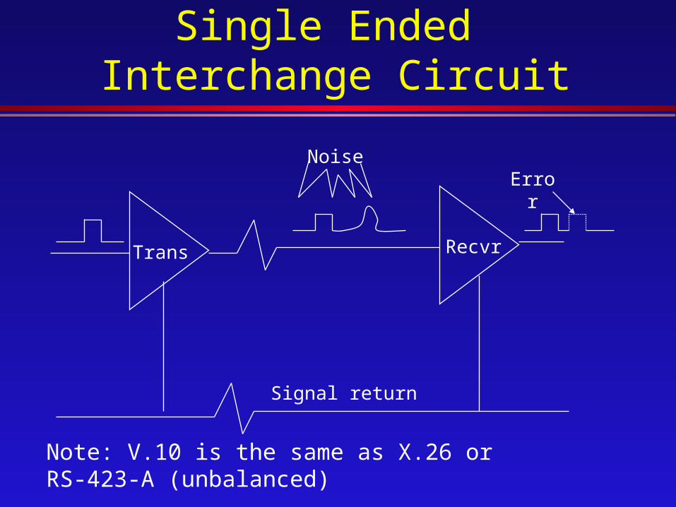
RS-423/CCITT V.10Single Ended Interchange
Circuit
Signal return
Trans Recvr
ErrorNoise
Note: V.10 is the same as X.26 or RS-423-A (unbalanced)
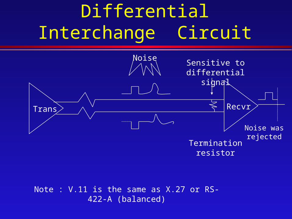
RS-422/CCITT V.11 Differential Interchange
Circuit
Trans Recvr
NoiseSensitive to
differential signal
Termination resistor
Noise was rejected
Note : V.11 is the same as X.27 or RS-422-A (balanced)
CCITT X.21 Interface
Physical-level interface between DTE and DCE
For synchronous operations on public data networks
X.21 uses control transitions and ASCII characters rather than using separate signal lines

CCITT X.21 Interface (Cont.)
The X.21 electrical characteristics are» CCITT X.27 (balanced; same as V.11 and
RS-422)» CCITT X.26 (unbalanced; V.10 and RS-
423)(Note: For operation above 9600 bit/s, X.27 is required)
X.21 mechanical characteristics are» 15-pin connector per ISO Standard 4903

CCITT X.21 Interface (Cont.)
X.21
Switched 64 kbit/s
DSU Bridge
4

CCITT X.21 Interface (Cont.)
Circuit Name DirectionTo DCE/To DTE
G Ground, Common ReturnGaGb
DTE Common ReturnDCE Common Return
X X
TR
TransmitReceive
X X
CI
ControlIndication
X X
SB
Signal TimingByte Timing (Optional)
X X
CCITT X.21 bis
As an interim (perhaps longer term) provision, we have X.21 bis
X.21 bis utilizes RS-232 for use with X.25
Particularly used in countries where X.21 has not yet become available

CCITT X.21 bis (Cont.)
RS-232 signals are used to represent X.21 events» To initiate the call
Some X.21 features are not supported» Call progress signals
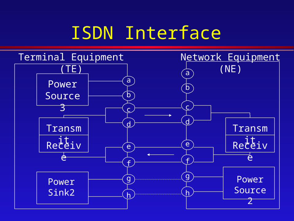
ISDN Interface
Power Source 3
Transmit
Receive
Power Source 2
Terminal Equipment (TE)
a
b
c
d
e
f
g
h
a
b
c
d
e
f
g
h
Transmit
Receive
Power Sink2
Network Equipment (NE)
COMPUTER NETWORK
Synchronous /Asynchronous Transmission

Asynchronous Timing
Asynchronous means no predefined timing between characters
The sending and receiving ends provide their own clocking
The timing of asynchronous characters is
T
Character
Start bit
Next Character
Start bit

Asynchronous Timing (Cont.)
The receiver does not know when the next unit of data is coming » The term async frequently is used this way
X.25
PAD
Async
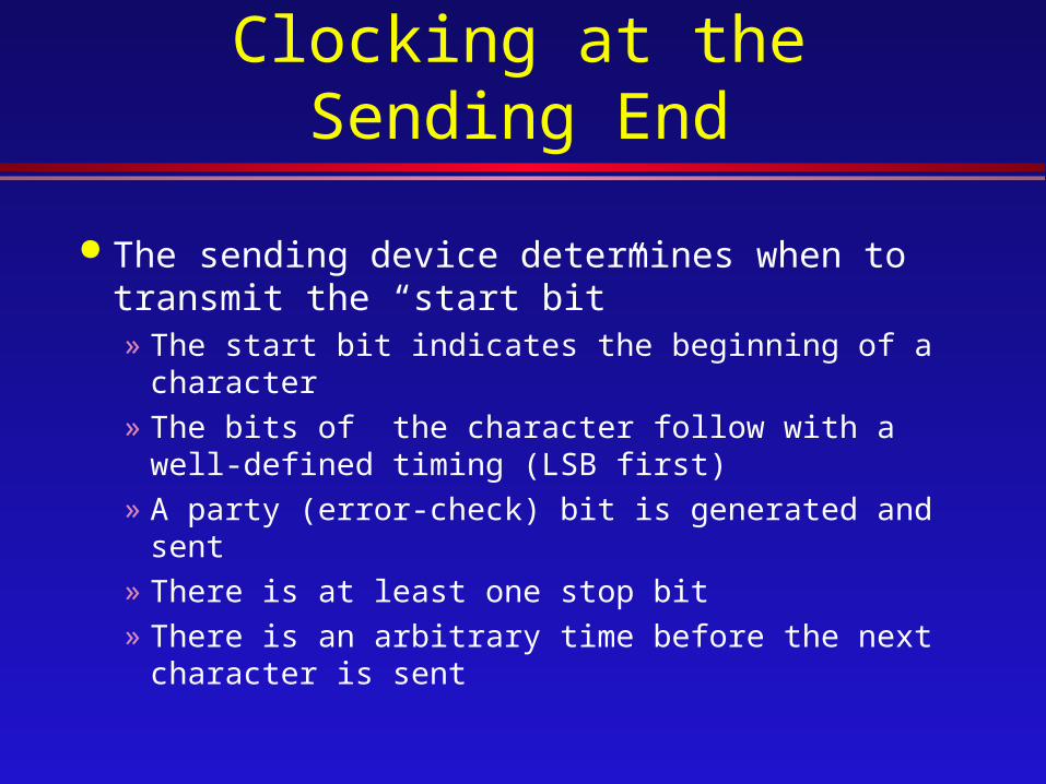
Clocking at the Sending End
The sending device determines when to transmit the “start bit”» The start bit indicates the beginning of a character» The bits of the character follow with a well-
defined timing (LSB first)» A party (error-check) bit is generated and sent» There is at least one stop bit» There is an arbitrary time before the next
character is sent
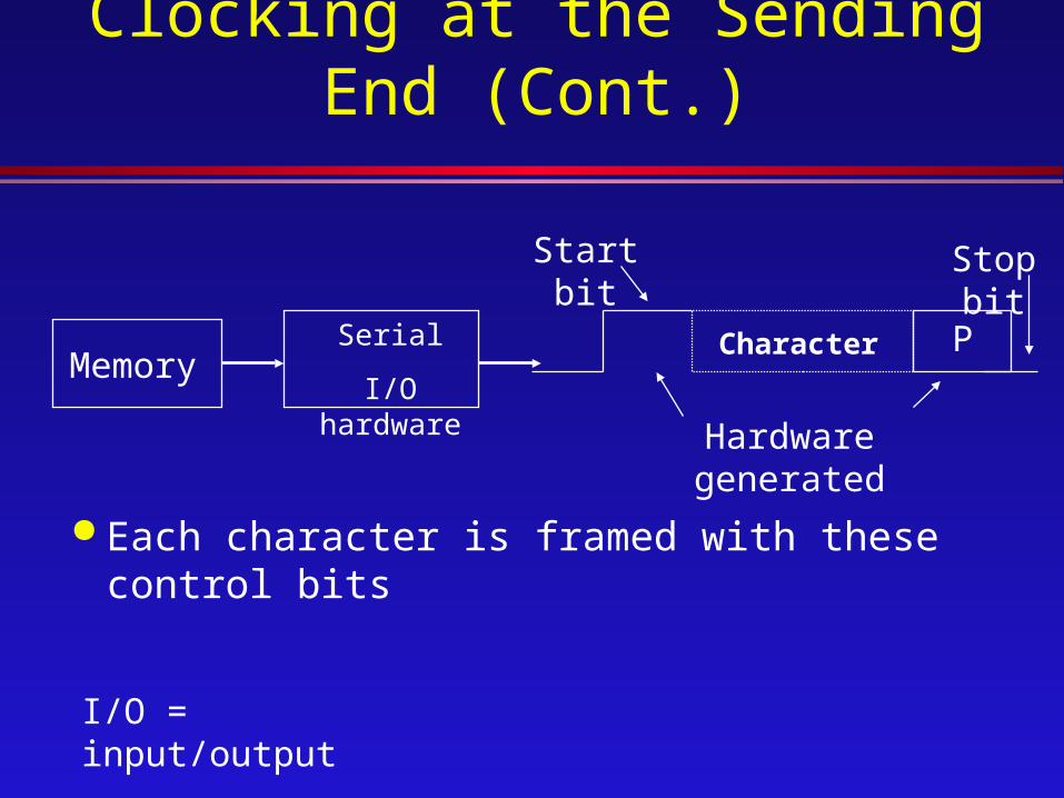
Clocking at the Sending End (Cont.)
Each character is framed with these control bits
MemorySerial
I/O hardware
Character
Start bit
P
Stop bit
Hardware generated
I/O = input/output
Synchronous Transmission
Has a known timing relationship between bits and characters
Characters are sent one after the other The receiver recovers this timing from
transitions in the arriving data
Start End
1
0
Characters

Modulation
We will explore methods used to transmit digital data across analog channels.
A primary example of analog channels is the telephone company’s voice-grade circuit.
There is one primary reason to use modems» To be compatible with the voice-grade channel

Modulation (Cont.)
The process of converting digital data into analog form is called modulation.
AnalogDigital
Generally, we get about 2 to3 bit/s per Hz of bandwidth of the analog channel (more or less based on complexity)

Data Communications Interfacing
Transmission line interface
device
Digital data transmitter/
receiver
Transmission line interface
device
Digital data transmitter/
receiver
Bit-serial transmission line
(or bit-serial interface to network
Data terminal equipment
(DTE)
Data circuit-terminating equipment
(DCE)
Generic interface to transmission medium

Data Communications Interfacing (Cont.)
Network
EIA 232/ V.24 interface
Modem Modem
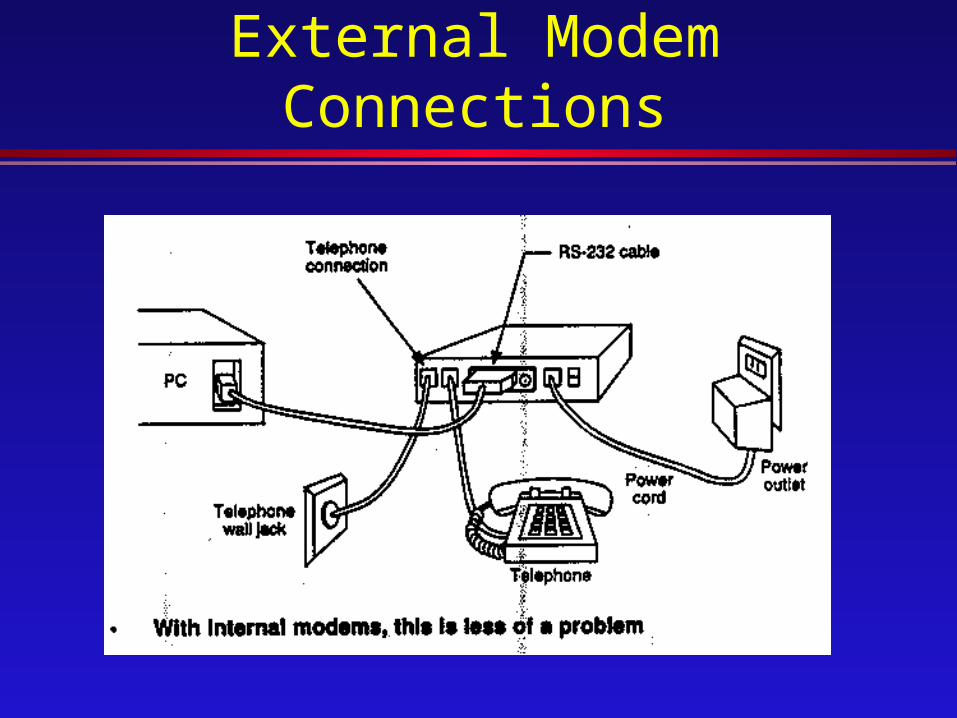
External Modem Connections

CCITT Modems
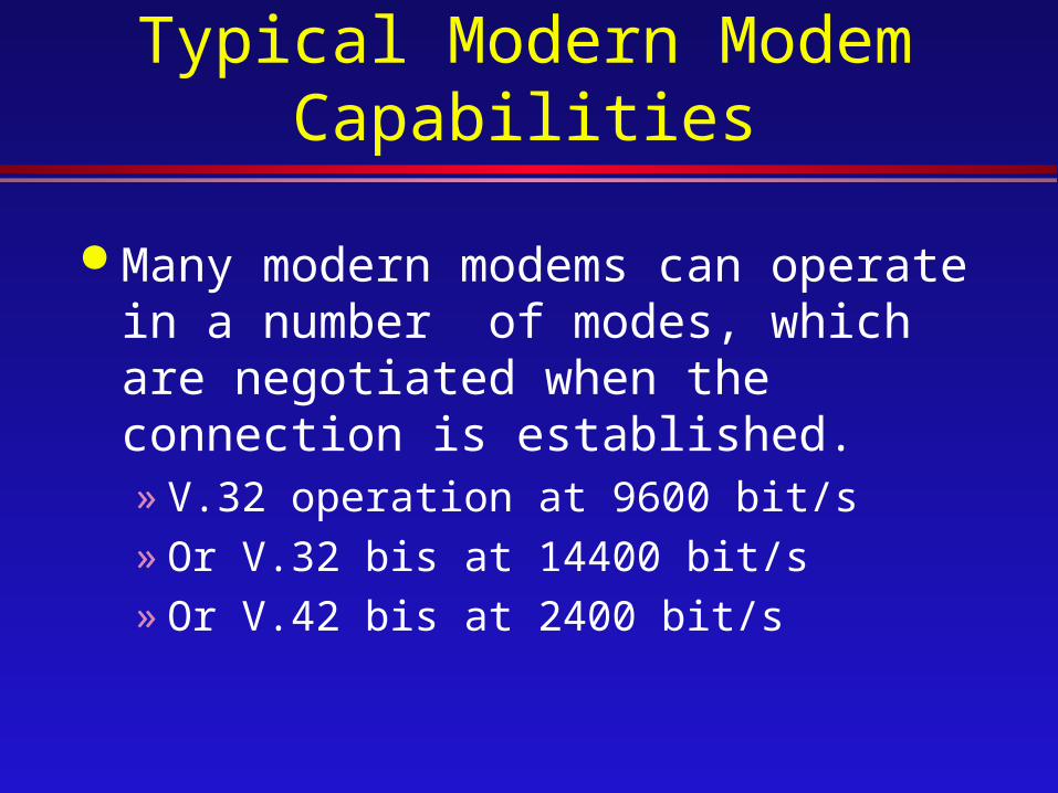
Typical Modern Modem Capabilities
Many modern modems can operate in a number of modes, which are negotiated when the connection is established.» V.32 operation at 9600 bit/s» Or V.32 bis at 14400 bit/s» Or V.42 bis at 2400 bit/s

Typical Modern Modem Capabilities (Cont.)
Modems can automatically dial the telephone number» V.25 bis sync/async autodial» Or the non-CCITT Hayes AT command set
(discussed later) Modems can perform operations previously
done by software» V.42 error correction (discussed later)» V.42 bis error compression (discussed later)

Typical Modern Modem Capabilities (Cont.)
Modems can “fall back” to a lesser data rate if needed for communications, and some can later “fall forward” when possible
Leased-line modems can automatically dial a backup line as needed.
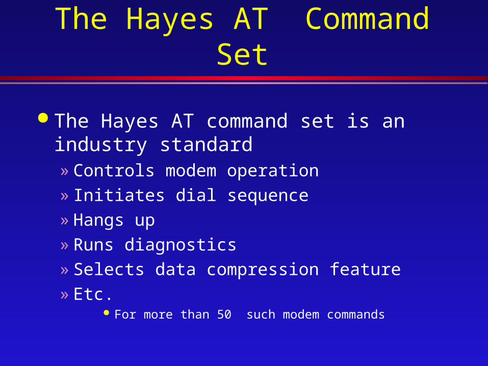
The Hayes AT Command Set
The Hayes AT command set is an industry standard» Controls modem operation» Initiates dial sequence» Hangs up» Runs diagnostics» Selects data compression feature» Etc.
For more than 50 such modem commands
The Hayes AT Command Set (Cont.)
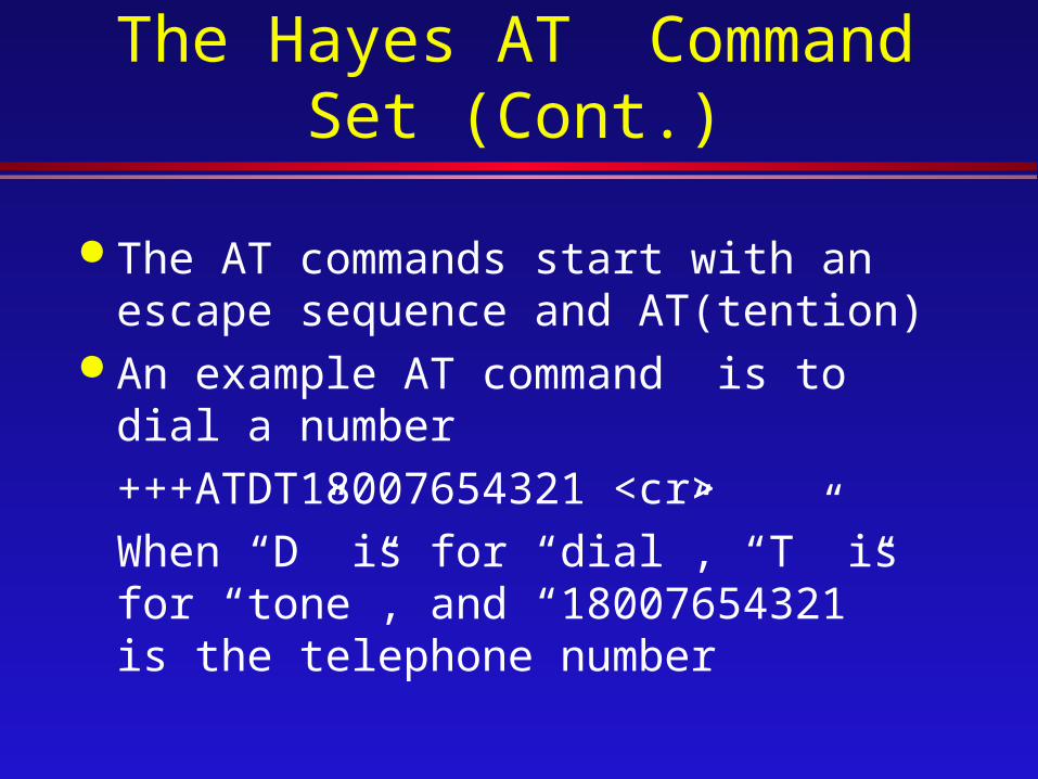
The AT commands start with an escape sequence and AT(tention)
An example AT command is to dial a number
+++ATDT18007654321 <cr>
When “D” is for “dial”, “T” is for “tone”, and “18007654321” is the telephone number
CCITT V.42 and V.42 bis Modern Capabilities
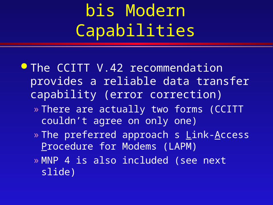
The CCITT V.42 recommendation provides a reliable data transfer capability (error correction)» There are actually two forms (CCITT
couldn’t agree on only one)» The preferred approach s Link-Access
Procedure for Modems (LAPM)» MNP 4 is also included (see next slide)

CCITT V.42 and V.42 bis Modern Capabilities (Cont.)
The CCITT recommendation V.42 bis builds on V.42» V.42 bis is a data compression standard» Uses an automatic adaptation algorithm
that handles different degrees of randomness in the data
» V.42 bis achieves a data compression factor of up to 4X

Microcom Network Protocol (MNP)
The Microcom Network Protocol (MNP) is a set of communications protocols for enhancing modem communications» Some are industry standards» Others are proprietary to Microcom
Three protocols are identified by terms such as » MNP 4, MNP class 4, or MNP level 4
Microcom Network Protocol (MNP) (Cont.)
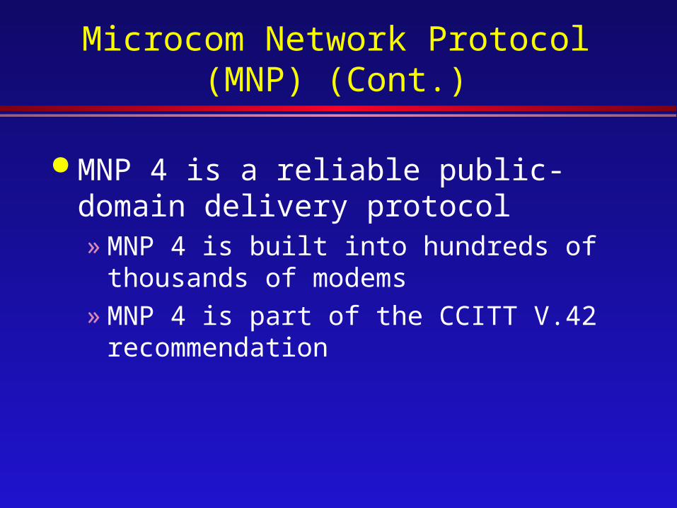
MNP 4 is a reliable public-domain delivery protocol» MNP 4 is built into hundreds of thousands
of modems» MNP 4 is part of the CCITT V.42
recommendation

XMODEM File Transfer Protocol (1978)
XMODEM was the first file transfer protocol for use with PCs» XMODEM actually predates PCs and DOS
XMODEM is available from many bulletin boards Transfers are limited in many ways
» Transfers data in small (128-byte) blocks» Operates as a simple “stop and wait” ACK/NAK
protocol» Inefficient use of links in excess of 1200 bit/s
XMODEM File Transfer Protocol (Cont.)
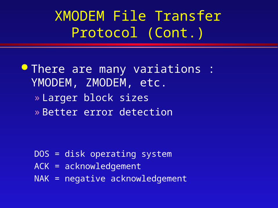
There are many variations : YMODEM, ZMODEM, etc.» Larger block sizes» Better error detection
DOS = disk operating system
ACK = acknowledgement
NAK = negative acknowledgement

XMODEM File Transfer Protocol (Cont.)
The operating mode is negotiated at connection establishment

Kermit (1981)
Kermit is available on many bulletin boards
Kermit was developed at Columbia University» Well documented» Intended for use between different
computers– Mainframes, minis, PCs

Kermit (Cont.)
All transmitted bytes are printable ASCII (except ASCII “SOH” start) 7-bit code» Avoids problems with control characters, for
example, which might affect PAD operation.
Remote-Control Software
The idea is that the remote PC takes over control of the office PC» Remote keyboard and screen “mirrors” the
other PC operations» For access to your office PC from a remote
PC; e.g. a laptop» Or, to assist a remote user without having
to go to that location

Remote-Control Software (Cont.)
Remote-control software is required in both PCs» A typical configuration is shown in our
example internetwork
PSTN
Remotely controlled
Roving laptop

Terminal Emulation
A terminal-emulation program allows your PC to appear to be a terminal hat a remote host knows how talk to » It may appear to be a scroll-mode terminal
(e.g., VT100)» It may appear to be a page-mode terminal
(e.g., an IBM 3270)

Terminal Emulation (Cont.)
Terminal emulation is a common approach» To log in at a host or server» To log in at any other device to access
services» For network management
–To read and write network management objects (variables)
Fax Modem Facts
Some modems provide facsimile (fax) as well as data capabilities
Two commonly used recommendations for fax transmission» V.29at 9600bit/s» V.17 at 14400 bit/s
Fax Modem Facts (Cont.)
Flow is unidirectional Support software is required
» Class 1: Minimal processing on the fax board
» Class 2: More on-board processing, less required by the PC

COMPUTER NETWORK
MULTIPLEXING
Multiplexing
It costs about the same amount of money to install and maintain a high bandwidth cable as a low bandwidth wire between two stations
Need for multiplexing techniques to share a single communication channel between multiple stations.

Two classes of multiplexing schemes :» Frequency Division Multiplexing (FDM)
The frequency spectrum is divided among the logical channel, with each station having exclusive possession of its frequency band. Filters limit the usable bandwidth per channel.
Multiplexing (Cont.)
Multiplexing (Cont.)
» Time Division Multiplexing
The stations take turns, each one periodically getting the entire bandwidth for a short interval of time.
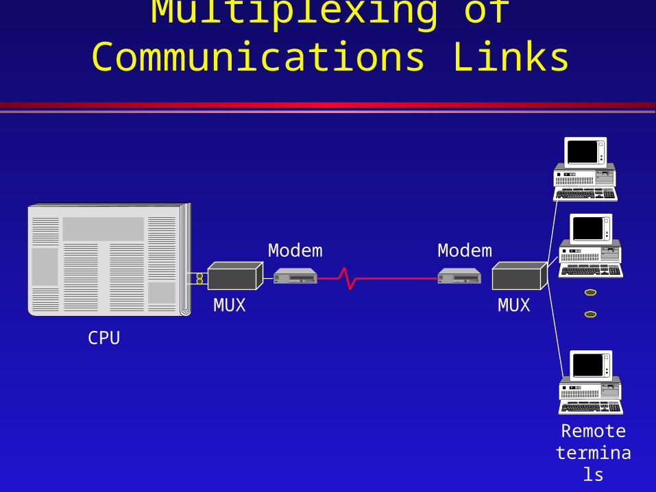
Multiplexing of Communications Links
MUX
Modem Modem
MUX
CPU
Remote terminals

Time Division Multiplexing
Each user gets the channel’s full capacity for a period of time
Each user gets a time slot in each frame
Start User NUser1 User2 User3 Start User1
One Frame One character of user data is sent in each slot If a user has nothing to send, the slot contains “null”
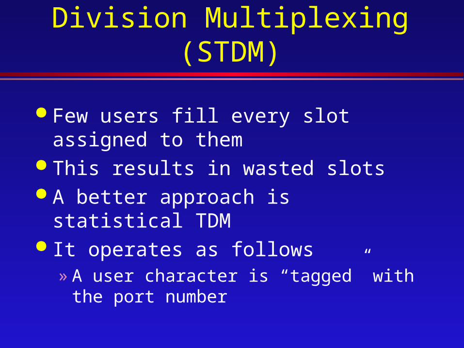
Statistical Time Division Multiplexing (STDM)
Few users fill every slot assigned to them
This results in wasted slots A better approach is statistical TDM It operates as follows
» A user character is “tagged” with the port number
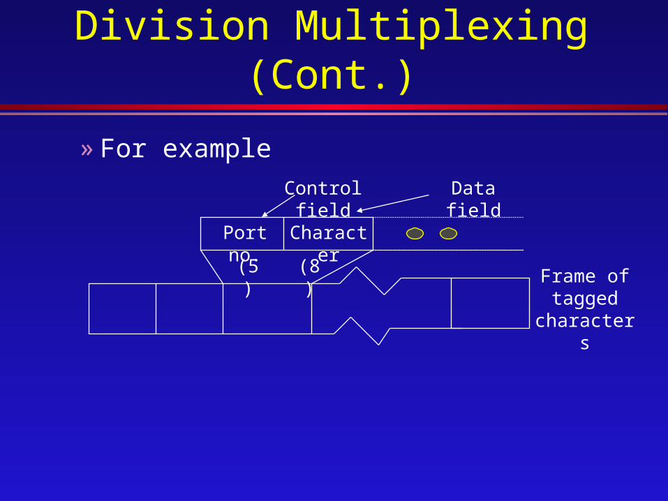
Statistical Time Division Multiplexing (Cont.)
Port no.
Character
Data fieldControl field
(5) (8) Frame of tagged
characters
» For example

Statistical Time Division Multiplexing (Cont.)
Statistical multiplexing can be generalized to produce packet switching
» More control information» Multiple characters of data

Typical Statistical Multiplexer (STAT MUX)
Example
CPU
MUX
Supervisory Terminal
Modem
Modem
MUX
Terminal
Printer