phys2250 introductory mechanics - university of hong …physlab/hoc203/2250-1 manual.pdf ·...
TRANSCRIPT
1
PHYS2250 Introductory mechanics
2250-1LABORATORYMANUAL
Experiment 1: Rotational Inertia of a Point of Mass Centripetal Force
conservation of Angular Momentum
Part A Rotational Inertia of a Point of Mass
Equipment Required:
Precision Timer Program, mass and hanger set, paper clips ( for masses < 1 g),
10-spoke pulley with photogate head, triple beam balance, calipers
Purpose:
The purpose of this experiment is to find the rotational inertia of a point mass
experimentally and to verify that this value corresponds to the calculated theoretical
value.
Theory:
Theoretically, the rotational inertia, I, of a point mass is given by I = MR2, where M is
the mass, R is the distance the mass is from the axis of rotation.
To find the rotational inertia experimentally, a known torque is applied to the object
and the resulting angular acceleration is measured.
Since 𝜏 = 𝐼𝛼, then 𝐼 = 𝜏/𝛼, where 𝛼 is the angular acceleration.
The linear acceleration a of the hanging mass is the tangential acceleration of the
rotating apparatus. The angular acceleration is related to the tangential acceleration as
follows: 𝛼 = 𝑎/𝑟, where r the radius of cylinder about which the thread is wound.
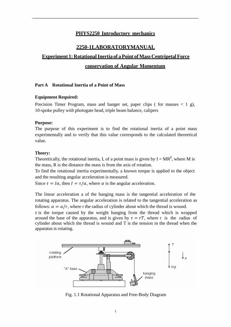
𝜏is the torque caused by the weight hanging from the thread which is wrapped
around the base of the apparatus, and is given by 𝜏 = 𝑟𝑇, where r is the radius of cylinder about which the thread is wound and T is the tension in the thread when the
apparatus is rotating.
Fig. 1.1 Rotational Apparatus and Free-Body Diagram
2
Applying Newton’s Second Law for the hanging mass, m, gives (see Fig. 1.1)
∑F mg − T ma
Solving for the tension in the thread gives:
T = m(g – a) and 𝜏= rT = rm(g – a)
Once the linear acceleration of the mass (m ) is determined, the torque and the angular
acceleration can be obtained for the calculation of the rotational inertia.
Setup:
Level the base. See Appendix 1
Attach the square mass (point mass) to the track on the rotating platform at any
radius you wish.
Mount the Smart Pulley to the base and connect it to a computer. See Appendix 1
Fig. A3.
Run the Science workshop program by clicking the appropriate icon on the desktop
of the computer.
Procedure:
Part1:Measurementsof theTheoreticalRotationalInertia
1. Weigh the square mass to find the mass M and record in Table 1.1
2. Measure the distance from the axis of rotation to the center of the square mass and
record this radius in Table 1.1.
Part 2: Measurement of the Rotational Inertia
Accounting for Friction
Because the theory used to find the rotational inertia experimentally does not include
friction, it will be compensated for in this experiment by finding out how much mass
over the pulley it takes to overcome kinetic friction and allow the mass to drop at a
constant speed. Then this “friction mass” will be subtracted from the mass used to
accelerate the ring.
1. To find the mass required to overcome kinetic friction, run “Science workshop ”.
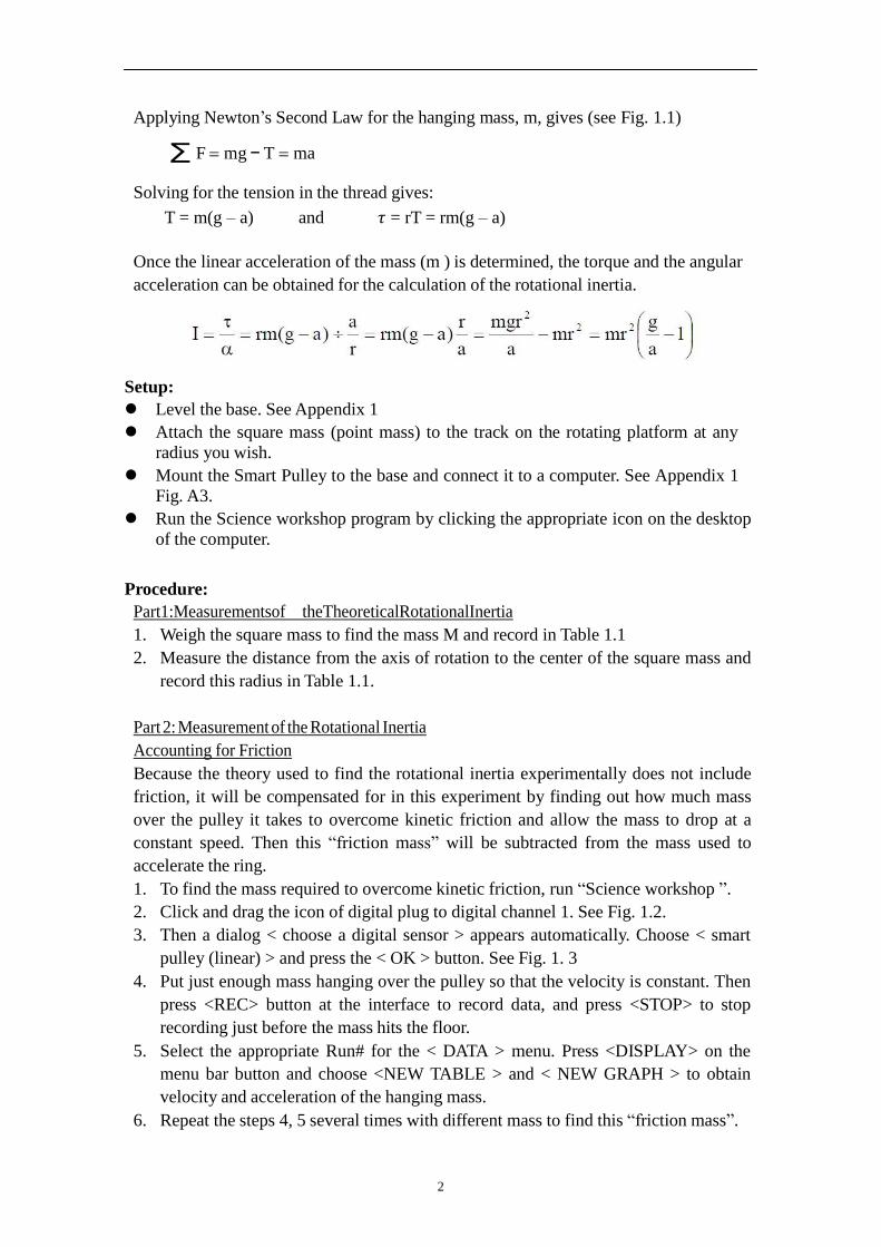
2. Click and drag the icon of digital plug to digital channel 1. See Fig. 1.2.
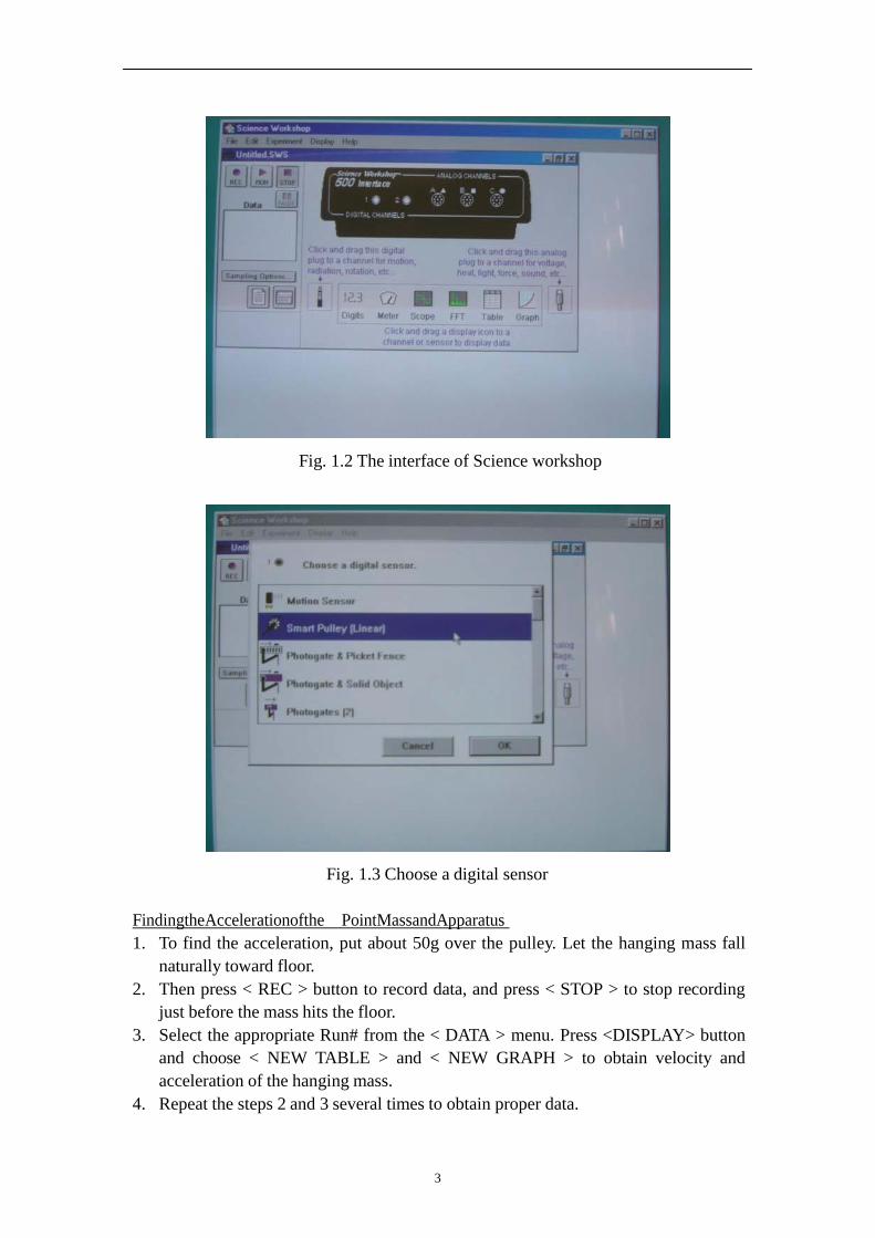
3. Then a dialog < choose a digital sensor > appears automatically. Choose < smart
pulley (linear) > and press the < OK > button. See Fig. 1. 3
4. Put just enough mass hanging over the pulley so that the velocity is constant. Then
press <REC> button at the interface to record data, and press <STOP> to stop
recording just before the mass hits the floor.
5. Select the appropriate Run# for the < DATA > menu. Press <DISPLAY> on the
menu bar button and choose <NEW TABLE > and < NEW GRAPH > to obtain
velocity and acceleration of the hanging mass.
6. Repeat the steps 4, 5 several times with different mass to find this “friction mass”.
3
Fig. 1.2 The interface of Science workshop
Fig. 1.3 Choose a digital sensor
FindingtheAccelerationofthe PointMassandApparatus
1. To find the acceleration, put about 50g over the pulley. Let the hanging mass fall
naturally toward floor.
2. Then press < REC > button to record data, and press < STOP > to stop recording
just before the mass hits the floor.
3. Select the appropriate Run# from the < DATA > menu. Press <DISPLAY> button
and choose < NEW TABLE > and < NEW GRAPH > to obtain velocity and
acceleration of the hanging mass.
4. Repeat the steps 2 and 3 several times to obtain proper data.

4
Measure theRadius
1. Using calipers, measure the diameter of the cylinder about which the thread is
wrapped and calculate the radius. Record in Table 1.2
Finding the Acceleration of the Apparatus Alone
Since in finding the acceleration of the point mass and apparatus is rotating as well as
the point mass, it is necessary to determine the acceleration, and the rotational inertia,
of the apparatus by itself so this rotational inertia can be subtracted from the total,
leaving only the rotational inertia of the point mass.
1. Take the point mass off the rotational apparatus and find the acceleration of the
apparatus alone.
Note that it will takes less “friction mass” to overcome the new kinetic friction
and it is only necessary to put about 20g over the pulley.
2. Record the data in Table 1.2
Calculations:
1. Subtract the “friction mass” from the hanging mass used to accelerate the
apparatus to determine the mass, m, to be used in equations.
2. Calculate the experimental value of the rotational inertia of the point mass and
apparatus together and record in Table 1.3.
3. Calculate the experimental value of the rotational inertia of the apparatus alone.
Record in Table 1.3.
4. Subtract the rotational inertia of the apparatus from the combined rotational inertia
of the point mass and apparatus. This will be the rotational inertia of the point
mass alone. Record in Table 1.3.
5. Calculate the theoretical value of the rotational inertia of the point mass. Record in
the Table 1.3.
6. Use a percent difference to compare the experimental value to the theoretical
value. Record in Table 1.3.
Part B Centripetal Force
Equipment needed:
Centripetal Force Accessory (Appendix 2), Rotating Platform (Appendix 1), Smart
Pulley photogate, balance, graph paper (2 sheets), mass and hanger set, string
Purpose:
The purpose of this experiment is to study the effects of varying the mass of the object,
the radius of the circle, the centripetal force on an object rotating in a circular path.
Theory:
When an object of mass m, attached to a string of length r, is rotated in a horizontal
circle, the centripetal force on the mass is given by
5
where v is the tangential velocity and 𝜔 is the angular speed (v = r𝜔). To measure
the velocity, the time for one rotation (the period, T) is measured. Then
and the centripetal force is given by
Setup:
Level the “A” base and rotating platform as described in the Appendix 1.
Procedure:
VaryRadius(Constantforce andmass)
1. The centripetal force and the mass of the hanging object will be held constant for
this part of the experiment. Weigh the object and record its mass in Table 2.1.
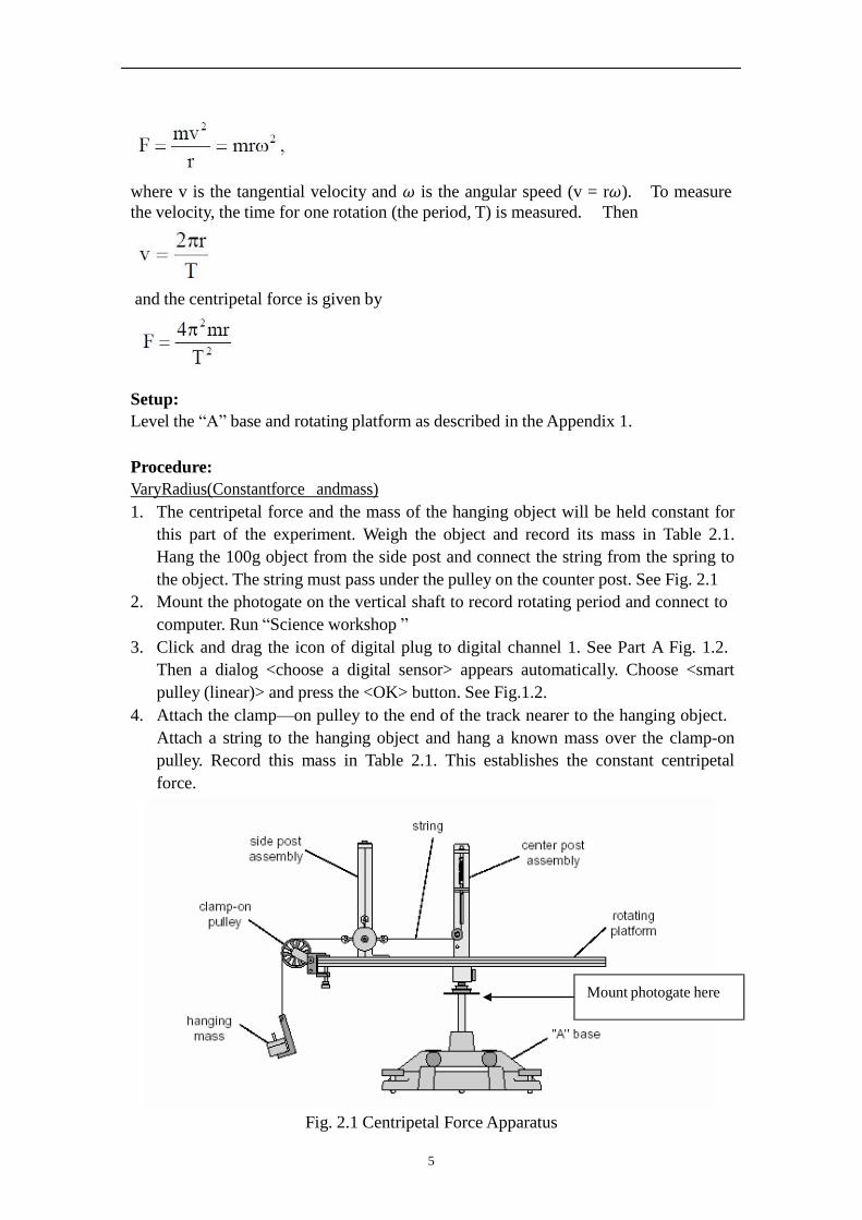
Hang the 100g object from the side post and connect the string from the spring to
the object. The string must pass under the pulley on the counter post. See Fig. 2.1
2. Mount the photogate on the vertical shaft to record rotating period and connect to
computer. Run “Science workshop ”
3. Click and drag the icon of digital plug to digital channel 1. See Part A Fig. 1.2.
Then a dialog <choose a digital sensor> appears automatically. Choose <smart
pulley (linear)> and press the <OK> button. See Fig.1.2.
4. Attach the clamp—on pulley to the end of the track nearer to the hanging object.
Attach a string to the hanging object and hang a known mass over the clamp-on
pulley. Record this mass in Table 2.1. This establishes the constant centripetal
force.
Mount photogate here
Fig. 2.1 Centripetal Force Apparatus
6
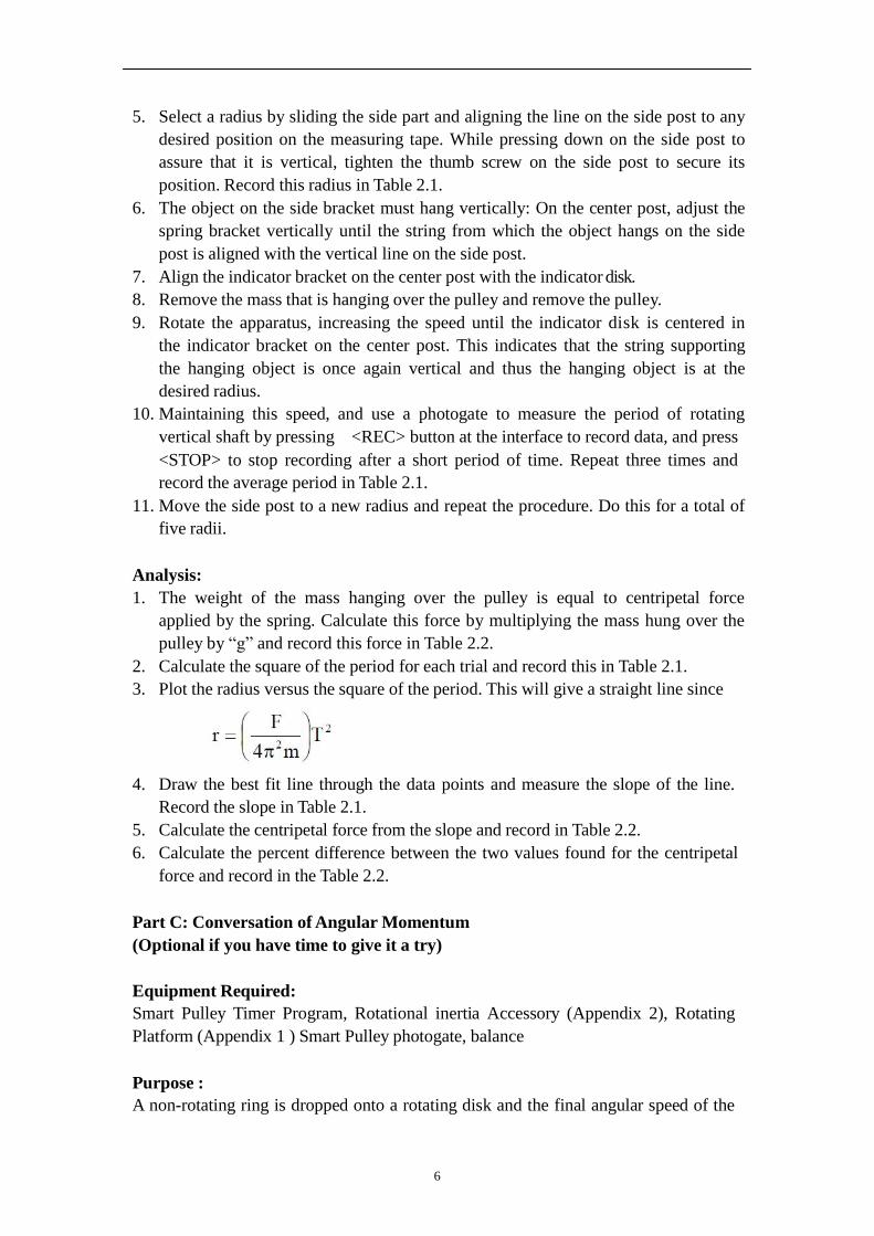
5. Select a radius by sliding the side part and aligning the line on the side post to any
desired position on the measuring tape. While pressing down on the side post to
assure that it is vertical, tighten the thumb screw on the side post to secure its
position. Record this radius in Table 2.1.
6. The object on the side bracket must hang vertically: On the center post, adjust the
spring bracket vertically until the string from which the object hangs on the side
post is aligned with the vertical line on the side post.
7. Align the indicator bracket on the center post with the indicator disk.
8. Remove the mass that is hanging over the pulley and remove the pulley.
9. Rotate the apparatus, increasing the speed until the indicator disk is centered in
the indicator bracket on the center post. This indicates that the string supporting
the hanging object is once again vertical and thus the hanging object is at the
desired radius.
10. Maintaining this speed, and use a photogate to measure the period of rotating
vertical shaft by pressing <REC> button at the interface to record data, and press
<STOP> to stop recording after a short period of time. Repeat three times and
record the average period in Table 2.1.
11. Move the side post to a new radius and repeat the procedure. Do this for a total of
five radii.
Analysis:
1. The weight of the mass hanging over the pulley is equal to centripetal force
applied by the spring. Calculate this force by multiplying the mass hung over the
pulley by “g” and record this force in Table 2.2.
2. Calculate the square of the period for each trial and record this in Table 2.1.
3. Plot the radius versus the square of the period. This will give a straight line since
4. Draw the best fit line through the data points and measure the slope of the line.
Record the slope in Table 2.1.
5. Calculate the centripetal force from the slope and record in Table 2.2.
6. Calculate the percent difference between the two values found for the centripetal
force and record in the Table 2.2.
Part C: Conversation of Angular Momentum
(Optional if you have time to give it a try)
Equipment Required:
Smart Pulley Timer Program, Rotational inertia Accessory (Appendix 2), Rotating
Platform (Appendix 1 ) Smart Pulley photogate, balance
Purpose :
A non-rotating ring is dropped onto a rotating disk and the final angular speed of the
7
system is compared with the value predicated using conversation of angular
momentum.
Theory:
When the ring is dropped onto the rotating disk, there is no net torque on the system
since the torque on the ring is equal and opposite to the torque on the disk. Therefore,
there is no change in angular momentum.
Angular momentum is conserved.
𝐿 = 𝐼𝑖𝜔𝑖 = 𝐼𝑓𝜔𝑓
where Ii is the initial rotational inertia and i is the initial angular speed. The initial
rotational inertia is that of a disk
1
2𝑀1𝑅
2,
and the final rotational inertia of the combined disk and ring is
So the final rotational speed is given by
Setup:
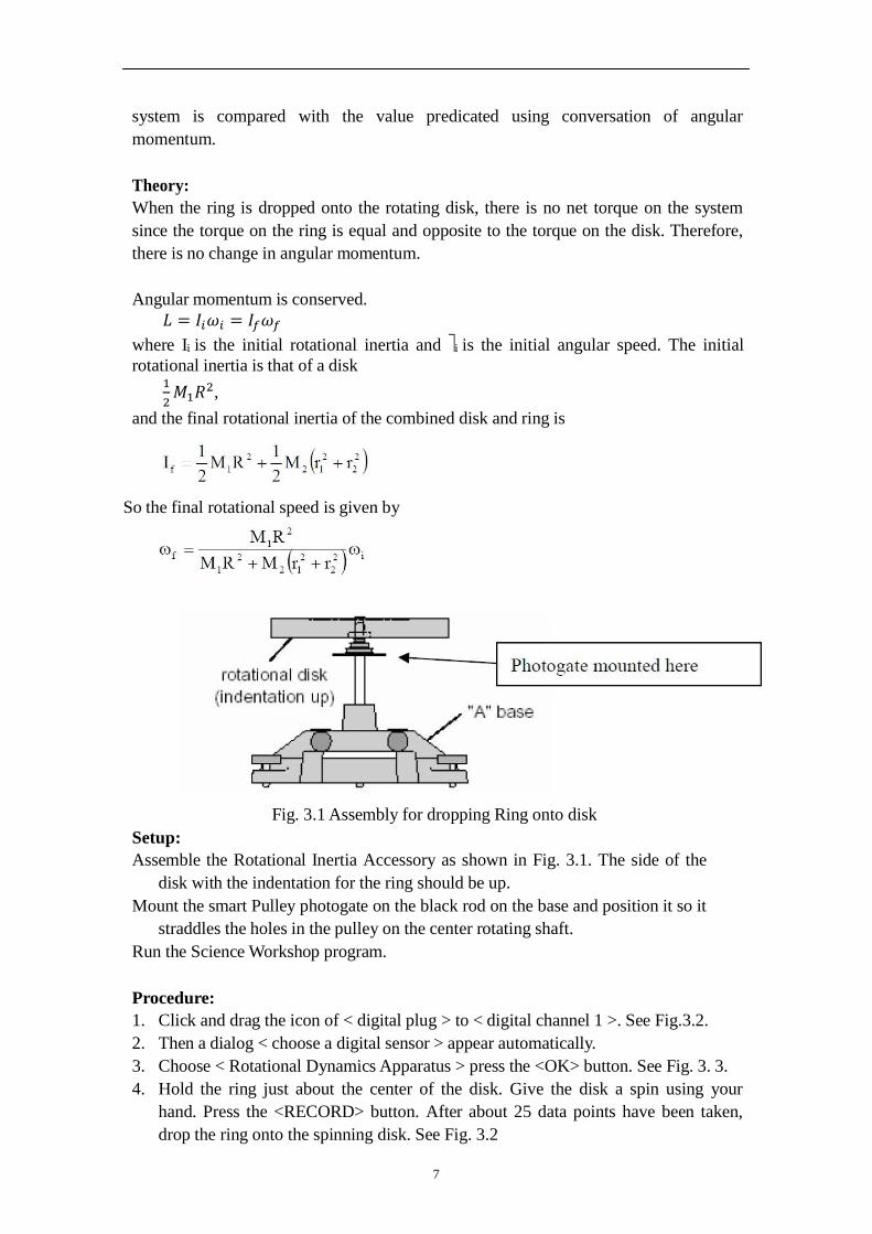
Fig. 3.1 Assembly for dropping Ring onto disk
Assemble the Rotational Inertia Accessory as shown in Fig. 3.1. The side of the
disk with the indentation for the ring should be up.
Mount the smart Pulley photogate on the black rod on the base and position it so it
straddles the holes in the pulley on the center rotating shaft.
Run the Science Workshop program.
Procedure:
1. Click and drag the icon of < digital plug > to < digital channel 1 >. See Fig.3.2.
2. Then a dialog < choose a digital sensor > appear automatically.
3. Choose < Rotational Dynamics Apparatus > press the <OK> button. See Fig. 3. 3.
4. Hold the ring just about the center of the disk. Give the disk a spin using your
hand. Press the <RECORD> button. After about 25 data points have been taken,
drop the ring onto the spinning disk. See Fig. 3.2

8
5. Continue to take data after the collision and then push <STOP> to stop recording
data.
6. Press <DISPLAY> button and choose Table and graph to obtain angular velocity
immediately before and immediately after the collision. Record these values in
Table 3.1.
7. Weigh the disk and ring and measure the radii. Record these values in Table 3.1.
Fig. 3.2 The interface of Science workshop
Fig. 3.3 Choose a digital sensor
9
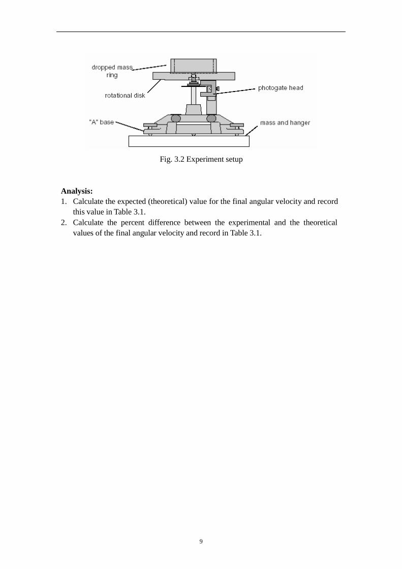
Fig. 3.2 Experiment setup
Analysis:
1. Calculate the expected (theoretical) value for the final angular velocity and record
this value in Table 3.1.
2. Calculate the percent difference between the experimental and the theoretical
values of the final angular velocity and record in Table 3.1.
10
Appendix 1
Assembling the Rotating Platform
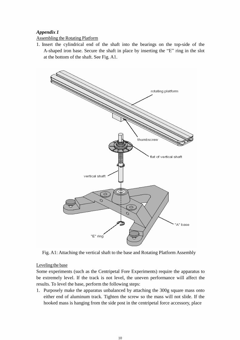
1. Insert the cylindrical end of the shaft into the bearings on the top-side of the
A-shaped iron base. Secure the shaft in place by inserting the “E” ring in the slot
at the bottom of the shaft. See Fig. A1.
Fig. A1: Attaching the vertical shaft to the base and Rotating Platform Assembly
Leveling the base
Some experiments (such as the Centripetal Fore Experiments) require the apparatus to
be extremely level. If the track is not level, the uneven performance will affect the
results. To level the base, perform the following steps:
1. Purposely make the apparatus unbalanced by attaching the 300g square mass onto
either end of aluminum track. Tighten the screw so the mass will not slide. If the
hooked mass is hanging from the side post in the centripetal force accessory, place

11
Figure A2: Levelling the Base
the square mass on the same side.
2. Adjust the leveling screw on one of the legs of the base until the end of the track
with the square mass on the same side.
3. Rotate the track 90 degrees so it is parallel to one side of the “A” and adjust the
other leveling screw until the track will stay in this position.
4. The track is now level and it should remain at rest regardless of its orientation.
To use the entire Smart Pulley with rod or the Super Pulley with rod:
1. Insert the Smart Pulley rod into the hole in the black rod and tighten the set screw
against the Smart Pulley rod. See Fig. A3.
2. Rotate the black rod so the string from the pulley on the center shaft is aligned
with the slot on the Smart Pulley.
3. Adjust the position of the base so the string passing over the Smart Pulley will
clear the edge of the Table.
Figure A3: Using the Accessory Mounting Rod with the
Photogate Mounting Rod and/or Smart Pulley
12
Appendix 2
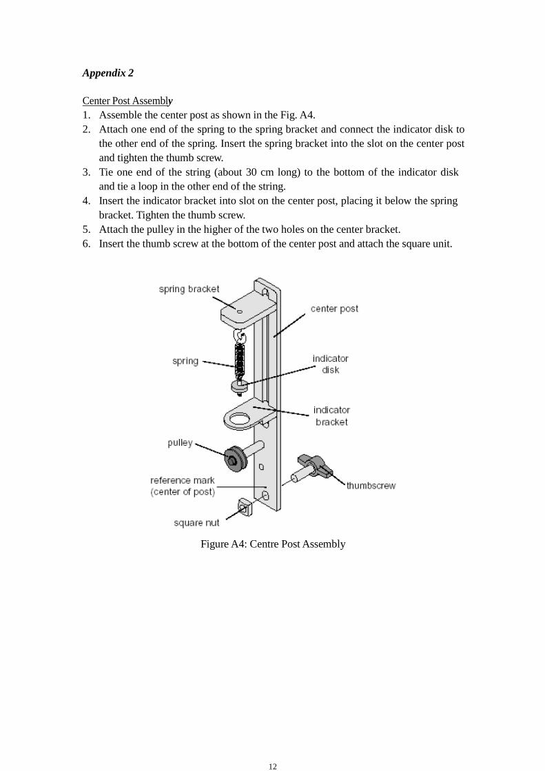
Center Post Assembly
1. Assemble the center post as shown in the Fig. A4.
2. Attach one end of the spring to the spring bracket and connect the indicator disk to
the other end of the spring. Insert the spring bracket into the slot on the center post
and tighten the thumb screw.
3. Tie one end of the string (about 30 cm long) to the bottom of the indicator disk
and tie a loop in the other end of the string.
4. Insert the indicator bracket into slot on the center post, placing it below the spring
bracket. Tighten the thumb screw.
5. Attach the pulley in the higher of the two holes on the center bracket.
6. Insert the thumb screw at the bottom of the center post and attach the square unit.
Figure A4: Centre Post Assembly
13
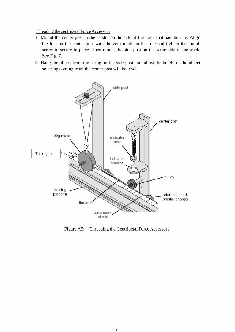
Threading the centripetal Force Accessory
1. Mount the center post in the T- slot on the side of the track that has the rule. Align
the line on the center post with the zero mark on the rule and tighten the thumb
screw to secure in place. Then mount the side post on the same side of the track.
See Fig. 7.
2. Hang the object from the string on the side post and adjust the height of the object
so string coming from the center post will be level.
The object
Figure A5: Threading the Centripetal Force Accessory