phys 322 chapter 9 interference lecture 25 reminder: exam
TRANSCRIPT

InterferenceChapter 9
Phys 322Lecture 25
InterferometersWavefront-splitting interferometersAmplitude-splitting interferometers Mirrored interferometers
Reminder: Exam 2 and Review quiz, more details on the course website

The Michelson interferometer
What if the path differences 2(d1-d2)=m? - minium, dark spot
What if the path differences 2(d1-d2)=m+/2? - maximum, bright spot
Compensator plateAlbert Abraham Michelson1852 - 1931
1881
+/2 - reflection
+/2 - reflection

The Michelson interferometer
Path difference: 2dcosPhase shift: (internal/external reflection)Minima: md cos2
What if light is white?
(©WIU OptoLab)

The Michelson interferometer: speed of light
Speed of light is constant in all reference systems
Michelson-Morley experiment

The Michelson interferometer: application
Accurate length measurements: Displacement of M2 by /2 fringe will move to the position occupied by an adjacent fringe
Count fringes, N:
d = N(0/2)

The Michelson Interferometer: advanced treatment
Beam-splitter
Inputbeam
Delay
Mirror
Mirror
Fringes (in delay):
*1 2 0 1 0 2
22 1 1 2 0 0
Re exp ( 2 ) exp ( 2 )
2 Re exp 2 ( ) ( /2)
2 1 cos( )
outI I I c E i t kz kL E i t kz kL
I I I ik L L I I I c E
I k L
since
L = 2(L2 – L1)
The Michelson Interferometer splits a beam into two and then recombines them at the same beam splitter.
Suppose the input beam is a plane wave:
Iout
L1
where: L = 2(L2 – L1)
L2 Outputbeam
“Bright fringe”“Dark fringe”

The Michelson Interferometer
Beam-splitter
Inputbeam
Delay
Mirror
Mirror
Another application of the Michelson Interferometer is to measure the wavelength of monochromatic light.
L = 2(L2 – L1)
Iout
L1
L2 Outputbeam
2 1 cos( ) 2 1 cos(2 / )outI I k L I L

Huge Michelson Interferometers may someday detect gravity waves.
Beam-splitter
Mirror
Mirror
L1
L2
Gravity waves (emitted by all massive objects) ever so slightly warp space-time. Relativity predicts them, but they’ve never been detected.
Supernovae and colliding black holes emit gravity waves that may be detectable.
Gravity waves are “quadrupole” waves, which stretch space in one direction and shrink it in another. They should cause one arm of a Michelson interferometer to stretch and the other to shrink.
Unfortunately, the relative distance (L1-L2 ~ 10-16 cm) is less than the width of a nucleus! So such measurements are very very difficult!
L1 and L2 = 4 km!

The LIGO project
A small fraction of one arm of the CalTech LIGO interferometer…
The building containing an arm
The control center
CalTech LIGO
Hanford LIGO
Laser Interferometer Gravitational-Wave Observatory

The LIGO folks think big…
The longer the interferometer arms, the better the sensitivity.
So put one in space, of course.

Interference is easy when the light wave is a monochromatic plane wave. What if it’s not?
For perfect sine waves, the two beams are either in phase or they’re not. What about a beam with a short coherence time????
The beams could be in phase some of the time and out of phase at other times, varying rapidly.
Remember that most optical measurements take a long time, so these variations will get averaged.

Delay = ½ period
(<< c):
Delay > c:
Constructive interference for all times (coherent) “Bright fringe”
Destructive interference for all times (coherent) “Dark fringe”)
Incoherent addition No fringes.
Delay = 0:
Adding a non-monochromatic wave to a delayed replica of itself

Suppose the input beam is not monochromatic(but is perfectly spatially coherent):
Iout = 2I + c Re{E(t+2L1 /c) E*(t+2L2 /c)}
Now, Iout will vary rapidly in time, and most detectors will simply integrate over a relatively long time, T :
/ 2 / 2
1 2
/ 2 / 2
( ) 2 Re ( 2 / ) *( 2 / )T T
out
T T
U I t dt U IT c E t L c E t L c dt
The Michelson Interferometer is a Fourier Transform Spectrometer
The Field Autocorrelation!
Beam-splitter
DelayMirror
L1
L2
2 Re ( ') *( ' 'U IT c E t E t dt
Fourier Transform of the Field Autocorrelation is the spectrum!!
Changing variables: t' = t + 2L1 /c and letting = 2(L2 - L1)/c and T

Fourier Transform Spectrometer Interferogram
The Michelson interferometer output—the interferogram—Fourier transforms to the spectrum.
Inte
grat
ed ir
radi
ance
0 Delay
Michelson interferometer integrated irradiance
2/
1/
Frequency
Inte
nsity
Spectrum
A Fourier Transform Spectrometer's detected light energy vs. delay is called an interferogram.

Fourier Transform Spectrometer Data
Interferogram
This interferogram is very narrow, so the spectrum is very broad.
Fourier Transform Spectrometers are most commonly used in the infrared where the fringes in delay are most easily generated. As a result, they are often called FTIR's.
Actual interferogram from a Fourier Transform Spectrometer

Fourier Transform Spectrometers
Maximum path difference: 1 mMinimum resolution: 0.005 /cmSpectral range: 1 to 18 mAccuracy: 10-3 /cm to 10-4 /cm Dynamic range: 19 bits (5 x 10⁵)
A compact commercial FT spectrometer from Nicolet
Fourier-transform spectrometers are now available for wave-lengths even in the UV! Strangely, they’re still called FTIR’s.

z
The UnbalancedMichelson Interferometer
Now, suppose an object isplaced in one arm. In additionto the usual spatial factor, one beam will have a spatiallyvarying phase, exp[2i(x,y)].
Now the cross term becomes:
Re{ exp[2i(x,y)] exp[-2ikx sin] }
Distorted fringes
(in position)
Place anobject inthis path
Misalign mirrors, so beams cross at an angle.
x
Beam-splitter
Inputbeam
Mirror
Mirror
exp[i(x,y)]
Iout(x)
x
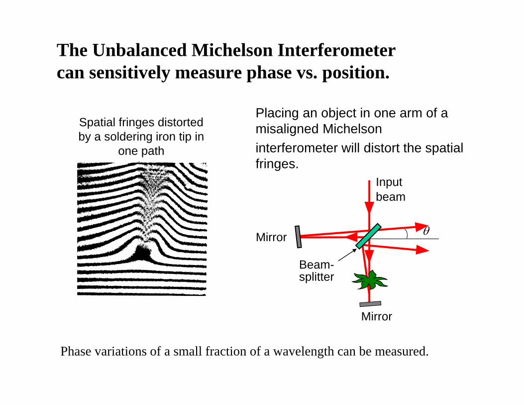
The Unbalanced Michelson Interferometercan sensitively measure phase vs. position.
Phase variations of a small fraction of a wavelength can be measured.
Placing an object in one arm of a misaligned Michelsoninterferometer will distort the spatial fringes.
Beam-splitter
Inputbeam
Mirror
Mirror
Spatial fringes distorted by a soldering iron tip in
one path
S S1 S2
M1 M2
P
cos2d
cos4 d
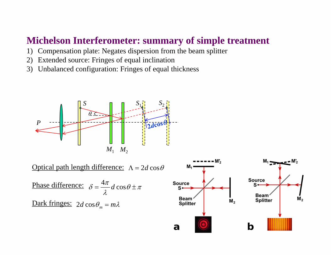
Optical path length difference:
Phase difference:
Dark fringes: md m cos2
Michelson Interferometer: summary of simple treatment1) Compensation plate: Negates dispersion from the beam splitter2) Extended source: Fringes of equal inclination3) Unbalanced configuration: Fringes of equal thickness

The Mach-Zehnder Interferometer
The Mach-Zehnder interferometer is usually operated misalignedand with something of interest in one arm.
Beam-splitter
Inputbeam
Mirror
Mirror
Beam-splitter
Output beam
Object

Mach-Zehnder Interferogram
Nothing in either path Plasma in one path

The Sagnac Interferometer
The two beams take the same path around the interferometer and the output light can either exit or return to the source.
Beam-splitter
Inputbeam
Mirror
Mirror
It turns out that no light exits! It all returns to the source!

Why all the light returns to the source in a Sagnac interferometer
For the exit beam:
Clockwise path has phase shifts of , , , and 0.
Counterclockwise path has phase shifts of 0, , , and 0.
Perfect cancellation!!
For the return beam: Clockwise path has phase shifts of , , , and 0. Counterclockwise path has phase shifts of 0, , , and . Constructive interference!
Beam-splitterInput
beam
Mirror
Mirror
Reflection off a front-surface mirror yields a phase shift of (180 degrees).
Reflective surface
Reflection off a back-surface mirror yields no phase shift.
Exit beam
Returnbeam

Rotating Sagnac InterferometerInterferometer rotates with angular velocity (classical treatment)
Travel AB:2
2v
c
RtAB
RcRtAB
2
2
Travel AD:Rc
RtAD
22
Time difference ( R<<c): 22
2 48cA
cRt

Rotating Sagnac Interferometer: example
Rotation of earth: = 2/24 hours = 7.27×10⁻⁵ s-1
side=500 m
24
cAt
28
-152
m/s103s1027.7m 0054
s 101.8 16t
Michelson and Gale, 1925
One period of light wave: /c = (500 nm)/(3×108 m/s)=1.7×10-15 s

Sagnac Interferometer: gyroscope