photonically synchronized large aperture radar for
TRANSCRIPT
Photonically synchronized large aperture radar for autonomous driving
STEFAN PREUSSLER,* FABIAN SCHWARTAU, JOERG SCHOEBEL, AND
THOMAS SCHNEIDER Institut fuer Hochfrequenztechnik, Technische Universitaet Braunschweig, Schleinitzstr. 22, 38106 Braunschweig, Germany * [email protected]
Abstract: Fully autonomous driving, even under bad weather conditions, can be enabled by the use of multiple sensor systems including 5D radar imaging. In order to get three dimensional, high resolution images with Doppler and time tracking of the target, the radar needs to utilize a large number of transmit/receive modules. For proper beam forming, all of them demand synchronization. Here a new concept for the optical distribution of radar signals, comprising low complexity integrated transmitter and receiver chips and a complex central station, will be introduced. Unavoidable temperature drifts due to environmental influences were compensated to maintain a continuous electrical output power. Within a proof-of-concept radar experiment an angular resolution of 1.1° has been achieved.
© 2019 Optical Society of America under the terms of the OSA Open Access Publishing Agreement
1. Introduction
Due to significant development efforts and dramatic progress that has been made within the last decade, self-driving, autonomous vehicles have been getting lots of attention. Among the many technologies that are used for autonomous vehicles is a combination of sensors and actuators, sophisticated algorithms, and powerful processors to execute software. In order to see and interpret what is in front of the autonomous car when going forward, conventionally cameras and Light Detection and Ranging (LIDAR) systems are used [1]. For close-in control, such as when parking, lane-changing, or in bumper-to-bumper traffic, the LIDAR system is not as effective. Additionally, its performance is limited by weather conditions, such as fog or heavy rain. Therefore, it is supplemented by radars built into the front and rear bumpers and sides of the vehicle. The operating frequency for these types of radar is usually 77 GHz, which has good RF propagation characteristics, and provides sufficient resolution [2].
In addition to the precise measurement of target parameters like distance, relative radial velocity and relative azimuth angle, the target separation turned out to be very important for high quality object detection, recognition and classification [3]. To enhance the spatial resolution of a radar system, multiple antennas in multiple-input, multiple-output (MIMO) configuration can be used, enabling high azimuth and elevation angular resolution at a wide field of view [4]. This type of radar requires a large number of transmit/receive (T/R) modules, wherein all of them must be phase and frequency synchronized so that a coherent transmitting/receiving beam can be constructed. The distribution of these signals through conventional methods such as coaxial cable or twisted pair not only introduces engineering complexities and signal loss, but also have limitation of bandwidth, data rate and transmission distance. Additionally, in electrical powered cars, high electromagnetic fields can result in interferences and a reduction of the signal to noise ratio. Reliability, maintainability aspects, and RF leakage over a period of time are other drawbacks of conventional copper based cables. In contrast, optical systems are immune to electromagnetic interferences and electromagnetic compatibility issues while providing large bandwidth with increased data rate [5,6].
Vol. 27, No. 2 | 21 Jan 2019 | OPTICS EXPRESS 1199
#346210 https://doi.org/10.1364/OE.27.001199 Journal © 2019 Received 28 Sep 2018; revised 4 Dec 2018; accepted 5 Dec 2018; published 15 Jan 2019

Although microwave-photonics technology is used in cable networks and sensors remoting, its application in radar is still being explored [7–11]. Microwave-photonics in radar has many applications starting from radio frequency front end, moving target indication filters, to radar signal processing [12,13]. Additionally, advancements in optical telecommunications have made the technology widely available and fully photonic-based radar is seen as an evolution to the next generation. In fact, microwave photonic systems with a performance exceeding that of state-of-the-art electrical radar systems have been shown [14]. In particular, today’s electronic transceivers cannot achieve the same frequency range without the use of several parallel architectures, and do not provide an equivalent precision, especially at high carrier frequencies.
For the last 25 years microwave photonic (MWP) systems have relied almost exclusively on discrete optoelectronic devices and standard optical fibers and fiber based components, which makes them not cost-effective enough for cars. However, nowadays, integrated microwave photonics aims at the incorporation of MWP components and subsystems in photonic circuits, which is crucial for the implementation of both low-cost and advanced analog optical front ends. Several major technologies like compound semiconductors (GaAs, InP), nonlinear crystals (LiNbO3), dielectrics (silica and silicon nitride based waveguides) and element semiconductor (silicon-on-insulator) are available for the realization [15,16]. However, each technology has its own specific strengths like light generation and detection, passive routing with low propagation loss, electronic integration, ease in packaging, etc. Additionally, photonic integrated circuit design poses significant design challenges at the component and system level. Therefore, the right technology needs to be chosen carefully in order to meet the high requirements on link gain, noise figure and spurious-free dynamic range, as an indicator for nonlinearities, for integrated microwave photonic realization. Additionally, integrated microwave-photonic systems are another roadmap for optically controlled antenna beams of radars with reconfigurability options [17]. However, the generation and distribution of RF signals in MIMO radars using a microwave photonic network, has not been proposed yet.
So far, photonics and optical fibers are hardly used in vehicles. This is mainly due to the low data rates that occur in a conventional car. In an electrically operated, autonomous vehicle, however, the resulting data rates even of individual sensors can be in the gigabit range. Additionally, in autonomous cars the entertainment of the passengers might become very important. Thus, the very fast processing of data from multiple sensors, internet access and the distribution of high-bandwidth video and audio content is only possible with high data rate channels. In electrically driven cars, there are also time-varying, high field strengths, which require electromagnetic-interference immune data connections [18–20]. With today's construction and connection technology easy to handle, robust and fully encapsulated optical connections can be made available, in which the actual optics does not come into contact with the environment of the vehicle. Due to the high bandwidths of the fibers, even very high frequencies such as the frequency modulated continuous wave (FMCW) radar signal of 77 GHz can be transmitted almost lossless. At the same time, optical fibers are very light and flexible. Optical fibers thus represent the ideal transmission medium in future autonomous electric vehicles.
In this paper, we introduce a new concept for a large aperture MIMO system with optical distribution of the radar signals. To make the entire system modular, flexible, expandable and updateable, the individual radar modules have to be as simple as possible, allowing for smaller size and flexible positioning. Additionally, the same carrier and ramp signal is distributed via a fiber optic network to each module. The analogue, unprocessed data is send back to the central station via the same optical fiber network. Furthermore, first measurements for the radar system are carried out, showing excellent angular resolution.
Vol. 27, No. 2 | 21 Jan 2019 | OPTICS EXPRESS 1200
2. Concept
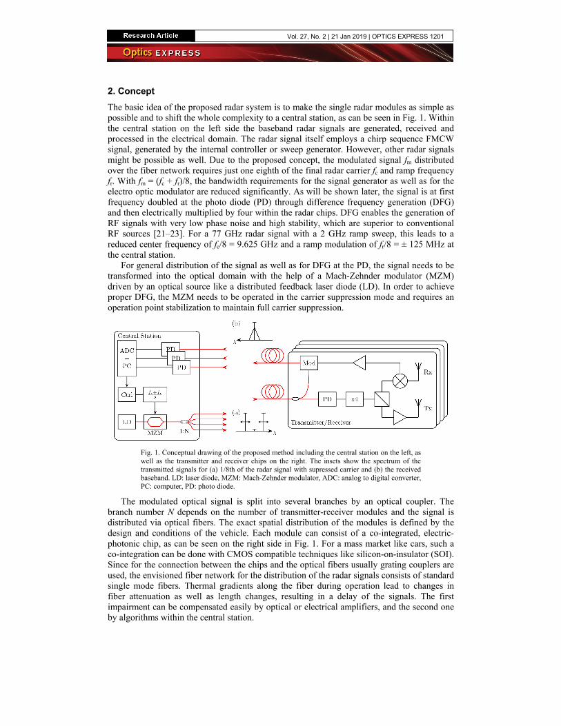
The basic idea of the proposed radar system is to make the single radar modules as simple as possible and to shift the whole complexity to a central station, as can be seen in Fig. 1. Within the central station on the left side the baseband radar signals are generated, received and processed in the electrical domain. The radar signal itself employs a chirp sequence FMCW signal, generated by the internal controller or sweep generator. However, other radar signals might be possible as well. Due to the proposed concept, the modulated signal fm distributed over the fiber network requires just one eighth of the final radar carrier fc and ramp frequency fr. With fm = (fc + fr)/8, the bandwidth requirements for the signal generator as well as for the electro optic modulator are reduced significantly. As will be shown later, the signal is at first frequency doubled at the photo diode (PD) through difference frequency generation (DFG) and then electrically multiplied by four within the radar chips. DFG enables the generation of RF signals with very low phase noise and high stability, which are superior to conventional RF sources [21–23]. For a 77 GHz radar signal with a 2 GHz ramp sweep, this leads to a reduced center frequency of fc/8 = 9.625 GHz and a ramp modulation of fr/8 = ± 125 MHz at the central station.
For general distribution of the signal as well as for DFG at the PD, the signal needs to be transformed into the optical domain with the help of a Mach-Zehnder modulator (MZM) driven by an optical source like a distributed feedback laser diode (LD). In order to achieve proper DFG, the MZM needs to be operated in the carrier suppression mode and requires an operation point stabilization to maintain full carrier suppression.
Fig. 1. Conceptual drawing of the proposed method including the central station on the left, as well as the transmitter and receiver chips on the right. The insets show the spectrum of the transmitted signals for (a) 1/8th of the radar signal with supressed carrier and (b) the received baseband. LD: laser diode, MZM: Mach-Zehnder modulator, ADC: analog to digital converter, PC: computer, PD: photo diode.
The modulated optical signal is split into several branches by an optical coupler. The branch number N depends on the number of transmitter-receiver modules and the signal is distributed via optical fibers. The exact spatial distribution of the modules is defined by the design and conditions of the vehicle. Each module can consist of a co-integrated, electric-photonic chip, as can be seen on the right side in Fig. 1. For a mass market like cars, such a co-integration can be done with CMOS compatible techniques like silicon-on-insulator (SOI). Since for the connection between the chips and the optical fibers usually grating couplers are used, the envisioned fiber network for the distribution of the radar signals consists of standard single mode fibers. Thermal gradients along the fiber during operation lead to changes in fiber attenuation as well as length changes, resulting in a delay of the signals. The first impairment can be compensated easily by optical or electrical amplifiers, and the second one by algorithms within the central station.
Vol. 27, No. 2 | 21 Jan 2019 | OPTICS EXPRESS 1201
For the back transmission of the analogue signal to the central station, the optical input is split. In the chip the DFG in a 20 GHz PD converts the 9.625 ± 0.125 GHz optical signal (inset (a) in Fig. 1) into a 19.25 GHz RF with a 500 MHz (19.25 ± 0.250 GHz) ramp. This signal is electrically multiplied by four in order to reach the final radar signal at 77 ± 1 GHz. In principle, an electrical frequency multiplier is a device with a nonlinear transfer function, which generates higher harmonics and subsequently selects the desired harmonic by filtering. Conventionally, varactor diodes, step recovery diodes or high power amplifiers are used. Lately, graphene transistors have been employed for frequency doubling with more than 90% converting efficiency [24].
Before radiation, the signal is electrically amplified. The received high frequency radar signal is down converted with an electrical mixer to the baseband. This low frequency signal is amplified and converted to the optical domain with an integrated modulator (Mod). Again just low bandwidth electrical and optical components are necessary. The baseband signal is transmitted back to the central station via a separate optical fiber (inset (b) in Fig. 1). Since the RF and ramp signal has a much higher frequency than the baseband signal, it can be simply separated by a low bandwidth photodiode at the central station. Instead of the star arrangement and a distinguished fiber for up and downlink, different wavelengths in one single fiber and a ring topology of the chips might be possible.
Back at the central station, the signal is converted to the electrical domain by a PD and further processed by electronics. Here, a bandwidth in the frequency range of the ramp (500 MHz) is sufficient. Finally, the signals from the different modules are processed by an analog to digital converter (ADC) and the radar image is generated via a PC.
Although becoming steadily cheaper, today optical devices like EDFA and single modulators might be too expensive for a cost sensitive market like automotive. However, on the one hand we believe that with the incorporation in a mass market the prices will fall drastically. On the other hand, as can be seen from Fig. 1, in the envisioned concept just one laser, modulator and one single EDFA, together with the low bandwidth photodiodes to receive the signal, would be required in the central station. The high number of radar modules are electronic-photonic integrated circuit (EPIC) chips, which are mass-market compatible and can be produced very cost effective. Additionally, most parts of the central station might be integrated on cost-effective chips as well.
3. Setup and characterization
In order to test the signal distribution and synchronization as well as the stability of the system, first proof-of-concept experiments were carried out, where several commercially available external radar chips are synchronized via optical fibers. The local oscillator (LO) signal of the commercial chips was 19.25 GHz. Thus, the synchronization signal had twice the frequency than in the concept, presented in the last section. The functionality of the proposed transmitter/receiver, including frequency multiplication by four and down conversion is provided by the used radar chips.
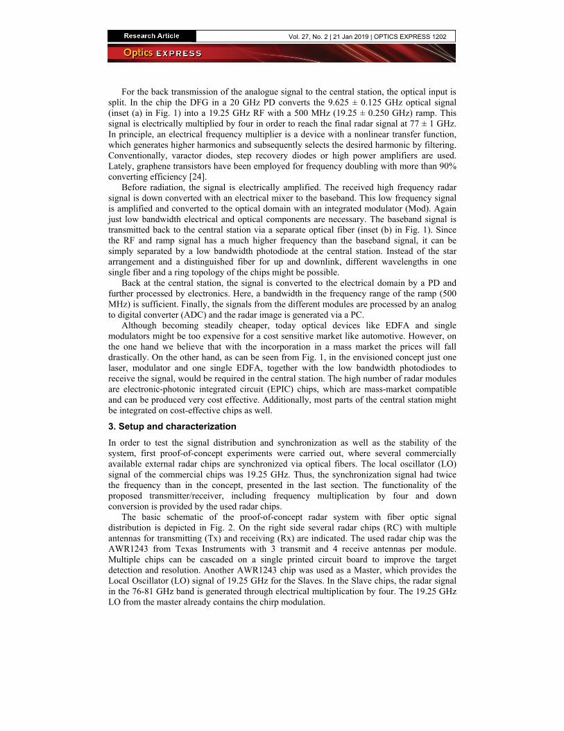
The basic schematic of the proof-of-concept radar system with fiber optic signal distribution is depicted in Fig. 2. On the right side several radar chips (RC) with multiple antennas for transmitting (Tx) and receiving (Rx) are indicated. The used radar chip was the AWR1243 from Texas Instruments with 3 transmit and 4 receive antennas per module. Multiple chips can be cascaded on a single printed circuit board to improve the target detection and resolution. Another AWR1243 chip was used as a Master, which provides the Local Oscillator (LO) signal of 19.25 GHz for the Slaves. In the Slave chips, the radar signal in the 76-81 GHz band is generated through electrical multiplication by four. The 19.25 GHz LO from the master already contains the chirp modulation.
Vol. 27, No. 2 | 21 Jan 2019 | OPTICS EXPRESS 1202

Fig. 2. Schematic of the proof-of-concept optically synchronized radar system. Single mode fiber optic connections are indicated by red lines and electrical connections by black ones. At the bottom, the link budget with measured optical and electrical output powers is displayed. The total link gain for the electrical signal from the master output to the RC input is zero, including the electrical-optical and optical-electrical conversion and all pre and post amplifiers. LDC: laser diode current controller, LD: laser diode, TEC: temperature controller, µC: microcontroller, PD: photo diode, EDFA: Erbium doped fiber amplifier, RC: radar chip.
In principle, the optical signal distribution and synchronization system consists of three main building blocks: an electrical to optical conversion, the distribution by optical single mode fibers and the back conversion into the electrical signal for each RC. The optical light source within the E/O block is a conventional distributed feedback laser diode (LD, JDSU CQF975/208) with a wavelength of 1547.40 nm, comprising narrow linewidth of 2 MHz, high side mode suppression ratio of 45 dB and a low relative intensity noise of −135 dBc/Hz. It is equipped with a laser diode driver module (LDC) that operates in constant current mode. Additionally, a compact and highly integrated temperature controller (TEC) optimized for use in high performance thermoelectric temperature control applications is applied to the LD. The output current is directly controlled to eliminate current surges and an adjustable TEC current limit provides the highest level of TEC protection. The synchronization signal from the Master chip is transferred into the optical domain with the help of a Mach-Zehnder modulator (MZM). Input polarization adjustment can be neglected since it is connected with a polarization maintaining fiber directly to the LD. The used MZM (OptiLab IM-1550-20-TQ) shows a usable bandwidth up to 20 GHz and a half wave voltage below 5 V.
A characterization of the complete signal distribution and synchronization system regarding the electrical input power against the electrical output power at the specified synchronization frequency of 19.25 GHz is depicted in Fig. 3(a). As can be seen, it shows saturation above an electrical input power of 18 dBm. Since the master chip just provides an electrical output power of 6 dBm, it needs to be amplified (Mini Circuits ZX60-183A) to guarantee proper operation.
In order to meet the requirements for automotive environment, all individual components, connectors and cables are chosen carefully to meet the operational range as specified by −40 to + 125°C. Nevertheless, during operation the heating of the waveguides in the modulator by the adjacent electrodes as well as changing environmental temperatures, lead to a drift of the operation point [25]. The higher the applied voltage, the higher the waveguides are heated. This leads to a length change, which is accompanied with a phase change and results in a change of the transmission at the output of the MZM. Especially the sideband carrier ratio is changing, leading to a severe change of the electrical signal after the PD. Therefore, a control loop was set up to stabilize the operation point for maximum transmission power. Thereby, the signal is fed through an inline fiber optic power monitor (Oplink ITMS), consisting of a 5% coupler and a low bandwidth photo diode. The received power is monitored by a microcontroller and maintained to a predefined setpoint. Additionally, the microcontroller
Vol. 27, No. 2 | 21 Jan 2019 | OPTICS EXPRESS 1203

enables voltatemperature sover time durthe operationdiodes, as diswith enabled remaining pow
Fig. 3moduwo/w
The seconsplit by a planthe different tens of meteroptical amplifshows a flat gelectrical ampof the EDFA within the prooptical link pafter the PDs.
The last bwhere the sigusing a photobandwidth ofcharacterizatioelectrical powrises with incrwill be a decaThe maximumoptical input pis electrically
age protection stabilization arering operation point, there isplayed by thestabilization. Awer changes ar
3. Electrical charlator operating postabilization.
nd main block nar lightwave cSlave modulesrs, where the fier (EDFA, Lgain response plifiers and to awas set to 17 doof of conceptower can be re
building block gnal from the o diode (PD) f typically 19on of the pho
wer of 18 dBm reasing opticalay and saturatim electrical outpower for a biaamplified (Mi
in order to ae shown in Figwithin a fixed
is a significane red trace in FAs can be seenre subjected to
racterization of thoint stabilization (
is the optical circuit coupler s. The length oattenuation ca
LiComm OFA-around the selachieve highesdBm. The overt experiment ceduced easily,
of the optical optical amplifas converter.
9 GHz and aoto diodes forcan be seen in
l input power aion of the electtput power (−4as voltage of 7ini Circuits ZX
avoid damage g. 3(b). The bld temperature ent drift of the Fig. 3(b). Then, a constant outhe resolution
he system (a) anb), black: tempera
amplifier and with a ratio ofof the fiber in an be neglecte-TCU) is stabilected wavelenst conversion erall link budge
can be seen in if electrical am
synchronizatiofier and splitte The used PDa responsivityr a modulationn Fig. 4(a). As as well as hightrical output po4 [email protected] 7 V. Before entX60-183A).
to the MZM.lack trace showenvironment. Welectrical outp
e green trace sutput power isof the microco
nd the measuremeature drift, red/gre
splitter modulf 1:4 in order to
the vehicle med. The outpuilized via autongth. Due to thefficiency at thet for the opticthe bottom ofmplifiers with
on is the opticaer is convertedD (Optilab PDy in the orden frequency oexpected, the
her bias voltageower for higheGHz) is achie
tering the slave
. Measuremenws the temperaWithout stabiliput power at tshows the meas maintained. Tontroller.
ent results of theeen: output power
le. The opticalo distribute the
might sum up tut of the erbiumatic light co
he restricted gahe PD, the outpal and electricf Fig. 2. In gen
h a higher gain
al to electrical d back into RD-20) has an er of 0.85 Aof 19.25 GHzelectrical outp
e. As can be seer optical inpu
eved for arounde radar chips, t
nts of the ature drift ization of the photo asurement The small
e r
l signal is e signal to to several um doped ontrol and ain of the put power al signals neral, the
n are used
receiver, RF signals
electrical A/W. The z with an put power een, there
ut powers. d 10 dBm the signal
Vol. 27, No. 2 | 21 Jan 2019 | OPTICS EXPRESS 1204

Fig. 4freque
Identical pare individualamplitude wethe use of proavoid distortio
The frequshown in Fig.20 GHz. Undshows a maxithe synchroni
4. Radar sys
The completesmaller moduchips and anantennas. In tavailable, whlocal oscillatoarrangement oboth in azimuand 12 Tx anazimuthal sca19.25 GHz rethe proof-of-required as wthe 19.25 GHoutput data oprocessing.
Figure 5 (distance) withseparated withthe cross cutdistance the hDoppler of a tplanned to incmodules. Acc
with HPBW
4. Measurement ofency response of th
performance oflly calibrated i
eight function. oper shielding aon due to comp
uency response. 4(b). Depend
der optimum coimum output pzation frequen
stem
e radar system ules (green prin FPGA. Thustotal, 5 differenich can be arra
or signal, but itof the master uth and elevatintennas in totaan, requiring jueference signalconcept, other
well, which wez LO signals is
of the radar ch
(right side) shh two targets h an angular set through the hardware of thetarget and trackcrease the resocording to [26,
= 50.8 /λ×
f the photo diode rhe whole signal di
f all receivers iin a near field In general, no
and groundingpression. e of the wholeding on the seleonditions regarpower of −2.2 ncy of 19.25 GH
can be seen iinted circuit bs, a module hnt modules witanged in differts Tx and Rx awith a perpenon. Each pair
al. For an initiust two of the fl transmission.r synchronizat
ere transmitted s fully integrat
hips is grabbed
hows the resultat 3.2 m dis
eparation of 1.detected patte
e demonstratork it over time,
olution far beyo p. 20] the hal
D , where λ i
response for differistribution and syn
is not critical, test range to
onlinear effect. The optical d
e signal distribected componerding optical adBm for lowerHz.
in Fig. 5 on thoards). Each mas a total of th different sparent orientationantennas are nodicular arrangeof modules prial test just twfour optical ca. Since commetion signals fovia coaxial ca
ted within the bd by an FPGA
t of a two-dimtance. The tar1°. The upper pern at the targr as presented which is calledond the presenlf power beam
is the wavelen
rent optical input pnchronization syste
since all the tradefine the dig
ts and distortiodevices are use
bution and synents, there is anand electrical inr frequencies a
he left side andmodule carries8 receive (Rxarse linear antens. One moduot used. Figureement of two
rovides a linearwo modules weables of the rigercial radar ch
for the procesables. The optblack box in th
A and transferr
mensional beamrgets are clearpart on the righget. Besides ain Fig. 5 is ca
d 5D radar imanted 1.1° by the
width (HPBW
ngth and D th
powers (a) and theem (b).
ansmit/receivegital value of pons are minimid in the linear
nchronization san increasing lonput power, thand around −4
d consists of ins two AWR12x) and 6 transenna configura
ule (master) dee 5 (left side) spairs of slaver sparse array ere used to pe
ght side in Fig. hips have beensing of the dtical synchronihe background.red to a PC fo
mforming (azimrly visible andht side of Fig. azimuth, elevaapable of measaging. Additione incorporation
W) can be appr
e width of an
e
e modules phase and ized with region to
system is oss above he system 4 dBm for
ndividual 243 radar smit (Tx) ations are livers the shows the modules of 16 Rx
erform an 2 for the
n used for data were ization of . The raw or further
muth and d can be 5 depicts
ation and suring the nally, it is n of more roximated
n aperture
Vol. 27, No. 2 | 21 Jan 2019 | OPTICS EXPRESS 1205

radiator. Follresulting in a
Fig. 5slave maste
5. Conclusio
In conclusionimaging systepossible indivinsulator techthat is capablsystem experimplementatioare selected cnonlinearities19.25 GHz ancompensated.resolution of integration anbad weather c
References
1. J. Levinson, Sokolsky, Gsystems and 168.
2. R. H. RasshoFunctions,” A
owing this, wlarger aperture
5. Demonstrator fomodules on the le
er and only two sla
on
n, we have shoem where all tvidual moduleshnology and are of transmittiriments with aon of an opticacarefully to en and distortionnd possible los Finally, the 1.1°. The pre
nd might lead tconditions.
J. Askeland, J. Be. Stanek, D. Stavenalgorithms,” in Pr
ofer and K. GresseAdv. Radio Sci. 3,
we can increase.
or the fiber optic eft side, as well asave modules on the
own a new cothe complexitys can be fabrice connected ving high frequealready existinal signal genernsure operationns. The systemss of synchron
whole radar esented radar to a high-resolu
ecker, J. Dolson, Dns, A. Teichman, Mroceedings of IEEE
er, “Automotive Ra, 205–209 (2005).
e the angular
synchronized radas a measurement oe right side.
ncept for a my is transferredcated in a masia a fiber opticency analog anng commerciaration and synn in the speci
m works well unization throug
system is chsystem showsution 5D senso
D. Held, S. KammeM. Werling, and SE Intelligent Vehic
adar and Lidar Sys
resolution by
ar system with onof the horizontal re
modular and fled to a central ss-production c network, leadnd digital dataal radar chips nchronization sified temperatuup to a synchr
gh thermal drifharacterized as high potentiaor for autonom
el, J. Z. Kolter, D.S. Thrun, “Towardcles Symposium (I
stems for Next Ge
y using more
ne master and fouresolution with one
exible MIMO station. The scompatible, siding to a robu. First proof-o
show the desystem. All comure range and ronization freqfts of the moduand shows anal for low cos
mous driving ev
Langer, O. Pink, Vds fully autonomouIV), (IEEE, 2011)
eneration Driver A
modules,
r e
5D radar imple-as-ilicon-on-st system f-concept
esign and mponents to avoid
quency of ulator are n angular st optical ven under
V. Pratt, M. us driving: , pp. 163–
Assistance
Vol. 27, No. 2 | 21 Jan 2019 | OPTICS EXPRESS 1206

3. R. H. Rasshofer, “Functional requirements of future automotive radar systems,” in Proceedings of European Radar Conference, (IEEE, 2007), pp. 259–262.
4. I. Bilik, O. Bialer, S. Villeval, H. Sharifi, K. Kona, M. Pan, D. Persechini, M. Musni, and K. Geary, “Automotive MIMO radar for urban environments,” in Proceedings of IEEE Radar Conference, (IEEE, 2016), pp. 1–6.
5. T. Berceli and P. Herczfeld, “Microwave photonics – a historical perspective,” IEEE Trans. Microw. Theory Tech. 58(11), 2992–3000 (2010).
6. J. Yao, “A Tutorial on microwave photonics,” IEEE Photonic Soc. Newslett. 26(3), 5–12 (2012). 7. A. S. Daryoush, “Optical synchronization of millimeter-wave oscillators for distributed architecture,” IEEE
Trans. Microw. Theory Tech. 38(5), 467–476 (1990). 8. A. Kanno, T. Umezawa, T. Kuri, N. Yamamoto, T. Kawanishi, and Y. N. Wijayanto, “Key technologies for
millimeter-wave distributed RADAR system over a radio over fiber network,” in Proceedings of International Conference on Radar, Antenna, Microwave, Electronics, and Telecommunications (ICRAMET), (IEEE, 2016), pp. 1–6.
9. M. F. Alam, M. Atiquzzaman, B. B. Duncan, H. Nguyen, and R. Kunath, “On board fiber-optic network architectures for radar and avionics signal distribution” NASA/TM-2000–209776.
10. A. J. Seed, “Microwave photonics,” J. Lightwave Technol. 21(12), 3104–3115 (2003). 11. J. Capmany and D. Novak, “Microwave photonics combines two worlds,” Nat. Photonics 1(6), 319–330 (2007). 12. S. Pan, D. Zue, and F. Zhang, “Microwave photonics for modern radar systems,” Trans. Nanjing Univ. Aeron.
Astron. 31(3), 219–240 (2015). 13. P. Ghelfi, F. Laghezza, F. Scotti, G. Serafino, S. Pinna, D. Onori, E. Lazzeri, and A. Bogoni, “Photonics in radar
systems: RF integration for state-of-the-art functionality,” IEEE Microw. Mag. 16(8), 74–83 (2015). 14. P. Ghelfi, F. Laghezza, F. Scotti, G. Serafino, A. Capria, S. Pinna, D. Onori, C. Porzi, M. Scaffardi, A.
Malacarne, V. Vercesi, E. Lazzeri, F. Berizzi, and A. Bogoni, “A fully photonics-based coherent radar system,” Nature 507(7492), 341–345 (2014).
15. D. Marpaung, C. Roeloffzen, R. Heideman, A. Leinse, S. Sales, and J. Capmany, “Integrated microwave photonics,” Laser Photonics Rev. 7(4), 506–538 (2013).
16. S. Iezekiel, “Integrated microwave photonics: a key enabling technology for radio-over-fiber,” Proc. SPIE 10128, 1012803 (2017).
17. M. Burla, D. Marpaung, L. Zhuang, M. R. Khan, A. Leinse, W. Beeker, M. Hoekman, R. G. Heideman, and C. G. H. Roeloffzen, “Multiwavelength-integrated optical beamformer based on wavelength division multiplexing for 2-D phased array antennas,” J. Lightwave Technol. 32(20), 3509–3520 (2014).
18. H. Zhao, G. Li, N. Wang, S. Zheng, L. Yu, and Y. Chen, “Study of EMC Problems with Vehicles,” in Proceedings of Communications in Computer and Information Science, (Springer, 2013), pp. 159–168.
19. S. Guttowski, S. Weber, E. Hoene, W. John, and H. Reichl, “EMC issues in cars with electric drives,” in Proceedings of IEEE Symposium on Electromagnetic Compatibility, (IEEE, 2003), pp. 777–782.
20. O. Strobel, Communication in Transportation systems (Information Science Reference, 2013). 21. S. Preußler, N. Wenzel, R.-P. Braun, N. Owschimikow, C. Vogel, A. Deninger, A. Zadok, U. Woggon, and T.
Schneider, “Generation of ultra-narrow, stable and tunable millimeter- and terahertz- waves with very low phase noise,” Opt. Express 21(20), 23950–23962 (2013).
22. M. Junker, M. J. Ammann, A. T. Schwarzbacher, J. Klinger, K.-U. Lauterbach, and T. Schneider, “A comparative test of Brillouin amplification and erbium-doped fiber amplification for the generation of millimeter waves with low phase noise properties,” IEEE Trans. Microw. Theory Tech. 54(4), 1576–1581 (2006).
23. T. Schneider, D. Hannover, and M. Junker, “Investigation of Brillouin Scattering in Optical Fibers for the Generation of Millimeter Waves,” J. Lightwave Technol. 24(1), 295–304 (2006).
24. H. M. D. Kabir and S. M. Salahuddin, “A frequency multiplier using three ambipolar graphene transistors,” Microelectronics J. 70, 12–15 (2017).
25. D. T. Bui, L. D. Nguyên, and B. Journet, “Improving the behavior of an electro-optic modulator by controlling its temperature,” in Proceedings of International Conference on Advanced Technologies for Communications, (IEEE, 2009), pp. 125–128.
26. R. J. Mailloux, Phased array antenna handbook (Artech House, 2005).
Vol. 27, No. 2 | 21 Jan 2019 | OPTICS EXPRESS 1207