photonic orthogonally polarized rf and microwave
TRANSCRIPT

Photonic orthogonally polarized RF and microwaveequalizers and single sideband generatormengxi tan
Swinburne University of Technologyxingyuan xu
monash universityDavid Moss ( [email protected] )
Swinburne University of Technology
Research Article
Keywords: Microwave photonics, micro-ring resonators, RF sideband generation
Posted Date: April 21st, 2021
DOI: https://doi.org/10.21203/rs.3.rs-444908/v1
License: This work is licensed under a Creative Commons Attribution 4.0 International License. Read Full License

8
1 Optical Sciences Centre, Swinburne University of Technology, Hawthorn, VIC 3122, Australia. 2 Electro-Photonics Laboratory, Dept. of Electrical and Computer Systems Engineering, Monash University, VIC3800, Australia. †
Corresponding e-mail: [email protected]
Abstract—We report narrowband orthogonally polarized optical RF single sideband generators as well as dual-channel RF equalization,
both based on high-Q integrated ring resonators. The devices operate in the optical telecommunications C-band and enable RF operation
over a range of either fixed or thermally tunable frequencies. They operate via TE/TM mode birefringence in the resonator. We achieve a
very large dynamic tuning range of over 55 dB for both the optical carrier-to-sideband ratio and the dual-channel RF equalization for both
the fixed and tunable devices.
Keywords — Microwave photonics, micro-ring resonators, RF sideband generation.
I. INTRODUCTION
Photonic microwave and radio frequency (RF) signal processing [1-4] has attracted substantial attention for a wide range of
applications because of the broad RF bandwidths that it can achieve, its high overall performance, its intrinsically lower loss, its very high reconfigurability and versatility, and finally its extremely high level of insensitivity to electro-magnetic interference. Its
main applications lie in the areas of radar, communications and sensing. Many different capabilities have been achieved, such as
advanced encoding format modulators [5-10], devices for RF beam shaping [11], RF signal processors based on transverse filtering
[12-14], RF channelizers [15] and spectrum analysis [16-18], and much more [19-38].
For RF photonic based systems, the optical RF signal modulation format directly impacts its transmission capacity as well as its
spectral efficiency. Hence. This is a key factor in the design of state-of-the-art photonic RF transmitters [39]. One advanced
modulation format, optical single sideband (OSSB) modulation, has attracted significant attention because of its high spectral
efficiency as well as its immunity to distortion induced by dispersion. Recently, a variation on this, termed orthogonally polarized OSSB modulation, has been proposed to increase the system flexibility as well as spectral efficiency. In this approach, the optical
sideband and the carrier are polarized in orthogonal directions. Another big advantage of orthogonally polarized OSSB modulation
is that it allows the individual control of both the optical sideband and the carrier by using polarization selective components.
Hence, it has been employed in many applications from photonic microwave signal processing to antenna beamforming systems
[39 - 43]. Many methods have been proposed to realize orthogonally polarized OSSB modulation, such as a differential group
delay module [42], acousto-optic modulation [43], modulators based on Sagnac-loops [44], quadrature phase shift keying dual-
polarization modulation [45], and polarization based modulation [46, 47]. Stimulated Brillouin scattering in optical fibers has been
reported, in order to control the optical signal polarization [48, 49]. Many of these methods, however, are limited in some respect. RF hybrid couplers create a bottleneck in system bandwidth, while fiber devices are bulky and limited in size reduction and stability
for practical real-world applications.
Other key components for RF systems are RF equalizers, which compensate any imbalance in passive component frequency
responses or variations in the gain profile of RF amplifiers [50, 51]. Significant work has been done on photonic based RF
equalizers including devices based on substrate-integrated waveguides [52, 53]. However, these methods have some limitations
including, again, a limited electronic bandwidth, and equalization resolution (minimum equalizing RF bandwidth), lack of RF
frequency tunability, and limited transmission spectrum dynamic range. Thus, for advanced RF systems that need high-resolution,
wideband RF equalization, and a large dynamic-range, more work is needed. A promising technique that can address these challenges is through the use of integrated microwave photonics [54]. Our approach also offers all of the attractions of photonic
integrated devices, that include a very small size, mass producibility, low power consumption, and high reliability [55].
Here, we present our recent work on orthogonally polarized OSSB generation and a dual-channel RF equalizer achieved through
the use of integrated dual-polarization micro-ring resonators (DP-MRR). This work involves both fixed [19] RF frequency and
tuneable RF frequency devices [20]. For fixed devices, a spectral interval of ~16.6 GHz and ~32.2 GHz between the TE and TM
polarized resonances of the DP-MRR is achieved. Lithographic control of the DP-MRR orthogonally polarized resonant mode
refractive indices can realize waveguides that have a virtually symmetric cross section, supporting both TM and TE polarizations, yet at the same time displaying quite wide TE to TM polarized spectral intervals of ~16.6 GHz or ~32.2 GHz in the C-band. Hence,
the optical sideband and carrier can be separated by looking at the drop-port, of the orthogonally polarized resonances, which
Photonic orthogonally polarized RF and microwave equalizers and single sideband generator
Mengxi Tan1, Xingyuan Xu1,2, David J. Moss1†

8
achieves orthogonally polarized OSSB modulation. Further, we convert the signal automatically from phase modulation to intensity
modulation by using the notches at the resonator through-port to suppress one of the sidebands, thus enabling dual-channel RF
filtering and equalization. Finally, a large dynamic tuning range of over 55 dB for both the optical carrier-to-sideband ratio of the OSSB signal can be achieved by controlling the polarization angle and extinction ratio of the dual-channel RF equalizer.
Subsequently, [20] a continuously RF frequency tunable OP-OSSB generator was reported, based on two different cascaded dual
integrated MRRs. The operation RF frequency of the tuneable OP-OSSB generator was determined by the TE to TM resonance
spectral interval, which could be tuned dynamically using individually controlled thermo-optical elements for each of the MRRs.
This, resulted in an operation bandwidth with a very wide RF tuning range. Further, by controlling the input light polarization
angle, we achieve a large a large optical carrier-to-sideband ratio (OCSR) dynamic tuning range of 57.3 dB. These results
emphasize the attractiveness of using polarization selective integrated micro-ring resonators to realise orthogonally polarized
optical single sideband modulators for RF signals at frequencies as high as 100GHz.
II. INTEGRATED MICRORING RESONATORS
The integrated micro-ring resonators (Figure 1) that formed the core components of the system were based on Hydex glass, a
high-index doped silica platform that features CMOS compatible processes [56 – 73]. First, a high refractive index (n = ~1.70 at
1550 nm) Hydex core was grown via PECVD (plasma enhanced chemical vapour deposition), followed by patterning via UV
stepper mask aligner based lithographically. Waveguides were then formed by dry etching (RIE - reactive ion etching) that achieved
very low surface roughness. Finally, an upper cladding consisting of silica glass (n = ~1.44 at 1550 nm) was grown. The radius of
the ring with the lower FSR of 49GHz (or 0.4nm), used for the fixed RF frequency device, was 592 μm,. The insertion loss of the through-port was 1.5 dB, via butt coupling with fibre pigtails and on-chip mode converters. The waveguide was almost symmetric
in cross-section (1.5 μm × 2 μm) so that the MRRs could exhibit TM and TE polarization modes. The theoretical TM and TE
modes (Figs. 1(b) and (c)) had effective indices neff_TM = 1.624 and neff_TE = 1.627, which produced marginally different FSRs for
the two polarizations, and with a comparatively wide TE/TM offset of TE//TM = ~16.6 GHz (Fig. 2) at 1550nm. The two
polarizations had comparable linewidths of ~ 140 MHz, or Q factors of about 1.2 million [62 - 66], and with a -20 dB bandwidth
of ~ 1 GHz (Fig. 2(b)). This narrow optical linewidth resulted in a very narrowband RF operation and provided a very sharp optical
filtering slope. This enabled operation as low as 500MHz, with a suppression of better than - 20 dB for unwanted sidebands. The
RF frequency can be varied by changing the TE/TM mode separation during fabrication by lithographic design of the waveguide
ring radius and cross-section. Hence, the frequency that was demonstrated here at 16.6-GHz is not a limitation of the orthogonally polarized OSSB generator or of the RF equalizer as well. Moreover, by using the complementary resonance, a second frequency
of operation at 32.4 GHz (= FSR − TE//TM) can also be realized. In general, ring resonators having FSRs of 200 GHz or even larger
[74] can be achieved, thus yielding operation at even higher RF frequency.
The ring resonators can be tuned thermally to match any optical carrier wavelength, to a resolution of less than 0.01 °C,
equivalent to megahertz level resolution, and with a response time on the order of milliseconds [75]. The DP-MRR transmission
spectra were measured as a function of temperature to illustrate the ability to achieve thermal tunability. The transmission spectra
are shown in Figures 3(a) and (b), for temperature tuning from 23 °C to 30 °C, showing the corresponding two TM resonances
(covering one FSR) and one TE resonance (marked as “TM1”, “TE” and “TM2” in Fig. 3(b), respectively). As shown in Fig. 3(c),
the resonance center wavelength redshifted at a rate of ~1.67 GHz/°C for TM and ~1.77 GHz/°C for TE polarization. Therefore,
Fig. 1. (a) Schematic illustration of the DP-MRR. (b) TE and (c) TM mode profiles of the DP-MRR.

8
the TE/TM mode offset, or birefringence, TE//TM varies with temperature slightly. Figure 3(d) shows the TE/TM mode splitting
( “TE”, “TM1” and “TM2”) versus temperature, revealing that the ~90 MHz/°C rate is much smaller than the -20 dB bandwidth
of the MRR (~1 GHz), but regardless can be compensated for by appropriate design of the waveguides (dispersion engineering).
For the orthogonally polarized OSSB system that was continuously tunable [20], we fabricated both 49GHz FSR and 200GHz FSR
integrated MRRs such that each ring exhibited both TM and TE polarizations. We used TM polarization for the first ring that had
the low FSR (49GHz), and TE polarization for the 2nd ring with the large FSR of 200GHz. As before, both waveguides were nearly symmetric (49GHz FSR at 1.5 μm × 2 μm and 200GHz FSR 1.45 μm × 1.5 μm), enabling both MRRs to support both polarizations. The difference between the effective indices between polarizations (49GHz MRR: TE: neff =1.627 TE mode and TM: neff = 1.624,
200GHz: TE: neff = 1.643 and TM neff =1.642) produced only a very small difference in FSRs between the polarizations, while still
showing a comparatively large TE/TM separation in absolute frequency in the C-band of ~16.8 GHz for the 49GHz FSR ring and
~41.2 GHz for the 200GHz MRR.. The 49GHz ring radius was ~592 μm as before, with Q = 1.5×10⁶, while the radius of the
200GHz MRR was ~135 μm, with Q = 1.2×10⁶. This reduced the leakage of the undesired sideband from the 200GHz MRR’s unused resonances. The measured transmission spectra are shown in Fig. 4 for both MRRs in which the FSRs and RF frequencies
are clearly illustrated.
Fig. 2. Experimental transmission spectra for the 49GHz FSR MRR. (a) Through-port (cyan, yellow) and drop-port (blue, red) transmission spectra of TE and
TM polarizations. (b) Drop-port transmission showing the FWHM resonances of 140 MHz, with Q > 1.2×10⁶.

8
Fig. 3. (a)−(b) OSSB generator transmission spectra for temperatures from 23 °C to 30 °C. Relation between chip temperature and (c) resonance central
wavelengths, (d) TE to TM resonance spacing.
Figure 4. Measured transmission spectra of the (49GHz FSR MRR) and 200GHz FSR MRR.

8
Figure 5. Principle of operation of the orthogonally polarized optical single sideband (OSSB) generator. EOM: electro-optical modulator. OSA: optical
spectrum analyzer. PC: polarization controller. POL: optical polarizer. LD: laser diode.. DSB: double sideband. DP-MRR: dual-polarization-mode micro-ring
resonator. OCSR: optical carrier to sideband ratio. (i) The 45o polarized carrier is modulated with dual side-bands. (ii) The carrier is transmitted by the DP-
MRR TM resonance and the upper sideband is passed by the DP-MRR TE resonance while the lower sideband is rejected by the DP-MRR. (iii) A polarizer
extracts the 45 o components of both upper sideband and carrier, projecting the SSB signal onto a single polarization.
Figure 6. Optical spectra of the generated orthogonally polarized OSSB signal.

8
III. ORTHOGONALLY POLARIZED OPTICAL SINGLE SIDEBAND GENERATOR
The architecture of the orthogonally polarized OSSB generator is shown in Figure 5. As discussed, the rings were designed to
support both polarizations, and yet still with a significant mode refractive index difference between them. We modulated a tunable CW laser to produce double sidebands (DSB). The signal was then coupled into the DP-MRR with a polarization angle of 45° to
the TE-axis (Fig. 5(i)). When wavelength of the pump and the RF frequency of the signal were each equal to one of the two
orthogonally polarized DP-MRR resonances, one generated DSB sideband together with the optical carrier signal were dropped
by the TE / TM resonances, thus producing orthogonally polarized OSSB modulated signals (Fig. 5(ii)). Further, we controlled the
relative fraction of TE versus TM light for the orthogonally polarized OSSB signal by passing the signal through a polarizer and
adjusting the polarization angle. This had the effect of tuning the optical carrier to sideband ratio (OCSR) for the single polarization
OSSB modulated signal.
The effective index difference between the polarizations yielded a strong dependence on polarization in the DP-MRR transmission spectrum. We employed the Jones matrix approach, where the eigenmodes of the DP-MRR are the polarization states
that provide a natural basis. Hence, the drop-port transmission of the DP-MRR becomes
0
0
TE
TM
DR
D
(3.1)
where DTM and DTE and are the drop-port transfer functions of the TM and TE modes given by
2
2
2
1TE
TE
TE
i
i
k aeD
t ae
(3.2)
2
2
2
1TM
TM
TM
i
i
k aeD
t ae
(3.3)
where k and t are the cross-coupling and transmission coefficients between the micro-ring and bus waveguide (t2 + k2 = 1 for zero
loss coupling), a is the transmission for a round-trip, ϕTM=2πL × neff_TM / λ and ϕTE = 2πL × neff_TE / λ are phase shifts for a single-pass of the TM and TE modes, respectively, and L is the length of the round-trip, and neff_TM and neff_TE are the effective indices for
the TM and TE modes.
The polarizer Jones matrix is
Figure 7. Transmission spectra of the OSSB generator with (a) θ = 2°, (b) θ = 42°, (c) θ = 92°, where θ denotes the polarization angle as shown in Figure 4.
(d)–(f) are zoom-in views of the shaded areas in (a)–(c), respectively.
8
2
2
sin cos sin( )
sin cos cosP
(3.4)
with θ being the angle between the TM axis and the direction of the polarize. For a general input field E0 [cos45°sin45°], the output field
after the polarizer is P(θ)RE0 [cos45°sin45°], or an output intensity of [76]
2 22 2
2
0( ) sin cos
2
sin 2 cos( )
TE TM
TE TM TE TM
EI D D
D D
(3.5)
where the input φTM and φTE are the complex phase angles of DTM.and DTE.
Hence, the dropped optical output power or induced loss due to polarization conversion by the TM and TE resonances is ~ cos2θ
or sin2θ, respectively. Specifically, when θ = 45°, the polarization conversion induced loss is 3 dB for both polarizations. The
OCSR (with carrier using the TM resonance and upper sideband the TE resonance) is
2OCSR( ) cot (3.6)
which can be tuned continuously by varying θ. Further, since cot2θ can be adjusted arbitrarily close to 0 or 1 as θ approaches π/2 or 0, an very high OCSR dynamic tuning range is obtained.
For the experiments, we tuned the laser to the 1550.47 nm TE resonance and modulated it in intensity at frequencies of 16.6
GHz or 32.4 GHz with an RF signal generator, so that both the lower and upper sidebands could be filtered out by the adjacent TM
resonance on the carrier’s long (red) or short (blue) wavelength sides. The orthogonally polarized carrier and the sidebands were
both obtained from the drop-port of the DP-MRR, with the optical power of the discarded sideband being attenuated by > 35 dB
in comparison with the signal sideband (Fig. 6).
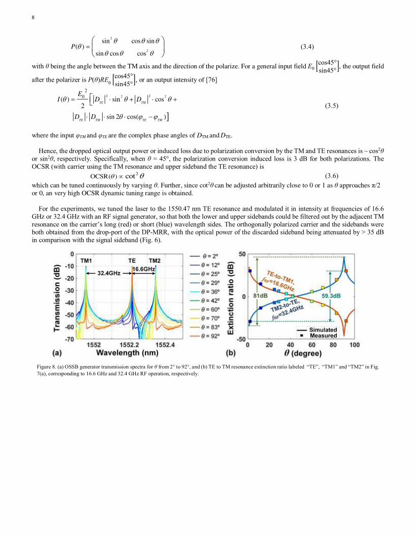
Figure 8. (a) OSSB generator transmission spectra for θ from 2° to 92°, and (b) TE to TM resonance extinction ratio labeled “TE”, “TM1” and “TM2” in Fig. 7(a), corresponding to 16.6 GHz and 32.4 GHz RF operation, respectively.

8
Next, we converted the orthogonally polarized OSSB signal to a single polarized OSSB signal via a polarizer, and by adjusting
the polarizer angle we were able to vary the OCSR. The transmission spectra of the OSSB generator with tunable OCSR is shown
in Fig. 7. As θ was tuned from 2° to 92°, the TE and TM extinction ratio varied from 30 dB to –29 dB, yielding a tuning range for the OCSR of 59.3 dB. The extinction ratios (Figs. 7(d) – (f)) clearly show that an RF operation frequency as high as 32.4 GHz was
achieved. Shows. The resulting extinction ratios and transmission spectra (Fig. 8) for RF operation at 16.6 GHz and 32.4GHz,
show that with a polarization angle varied from 2° to 92°, good agreement was achieved with theory. From Fig. 8(b), a large
dynamic range of 80 dB is anticipated and this can be accomplished by varying θ with a much more fine resolution.
The generated 16.6 GHz and 32.4 GHz single-polarization OSSB optical spectra signals (Fig. 9) show that a continuously tunable
OCSR is achieved, with a range of −22.7 to 41.4 dB and −27.1 to 52.2 dB. This illustrates the high performance and practicality
of the OSSB generator that features a tunable OCSR. Finally, carrier to sideband shifts of greater than one FSR can result in een
larger RF frequencies with the same device, which in our case correspond to 65.6 GHz = 16.6 GHz + FSR and 81.4 GHz = 32.4 GHz + FSR, and so on for higher frequencies.
The fact that the ring resonators had quite a high Q of over a million meant that the device achieved a high RF selectivity for
the OSSB generation. In principle this could yield a self-oscillating source at high frequency that operates through optoelectronic
oscillation, which is a powerful approach to obtain a very low phase noise. This is important for many applications, such as delivery
of RF standards over long-distances. In this regard, the OSSB modulation format excels since it is immune to RF power fading
arising from all dispersion effects. Hence our device can be applied to a very wide range of technical fields including even telescope
arrays for radio astronomy.
IV. RF EQUALIZER
Here we turn to the RF photonic equalizer that was also based on the DP-MRRs (Fig. 10). For this device, an RF signal was
used to phase modulate a CW tunable laser, which produced dual sidebands that had opposite phases, and with an angle of θ
between the TE-axis and polarization direction (Fig. 10(i)). Next, the TE and TM phase-modulated signal components were filtered
out by the two orthogonally polarized ring resonances (notches) (Fig. 10(ii)), where the imbalance between the two oppositely
phased sidebands was produced in order to convert from phase to intensity modulation. Following this, the filtered orthogonally
polarized optical signals were converted to RF signals and then combined after photodetection. Effectively, therefore, the high-Q
orthogonally polarized optical resonances were translated into the RF domain (Fig. 10(iii)), which resulted in a high RF frequency selective filter with dual passbands and with a bandwidth determined by the Q factor of the DP-MRR. The centre frequencies were
given by the relative spacing of the optical carrier to the adjacent resonance. By varying the polarization angle θ, the fraction of
TM to TE light was varied continuously, with an extinction ratio between the dual RF passbands able to be tuned to perform RF
equalization after mapping optical signal to the RF domain [77].
The DP-MRR transmission through-port is
0
0
TE
TM
TR
T
(4.1)
where TTE and TTM are the through-port transfer functions of the DP-MRR given by
2
(1 )
1TE
TE
TE
i
i
t aeT
t ae
(4.2)
Figure 9. OSSB generated signal optical spectra with a continuously tuneable optical carrier-to-sideband ratio (OCSR) driven by RF signals at (a) 16.6 GHz
and (b) 32.4 GHz. The 16.6 GHz and 32.4 GHz RF sidebands were dropped via the “TM2” and “TM1” resonances, while the optical carrier was dropped by
the “TE” resonance, as marked.

8
2
(1 )
1TM
TM
TM
i
i
t aeT
t ae
(4.3)
For a phase modulated optical signal E0 [cosθsinθ
], the DP-MRR output fields are
0 0
coscos
sin sin
TE
TM
ii
TE RE E
T
(4.4)
This equation shows that the RF passband center frequencies supported by the TE / TM resonances are determined by the relative frequency gap between the MRR resonances and the optical carrier, thus yielding tunable operation regions for the RF equalizer.
Moreover, the TE and TM polarized optical signal power is ~ cos2θ or sin2θ, respectively. Hence, after being detected the RF
passband extinction ratio (corresponding to the DP-MRR’s TE- and TM-polarized resonances) is given by
2
ER( ) cot (4.5)
The same as for the tunable OCSR for OSSB generation, the ER(θ) can be continuously varied by adjusting θ, and since cot2θ can
get arbitrarily close to 1 or 0 as θ nears 0 or π/2 (limited only by the polarizer performance), a large extinction ratio tuning range
results, reflecting a very large RF equalization dynamic range.
The experiments first investigated the tunability and resolution of a single RF passband by setting the input optical signal to TM-polarized (θ = 90º). The RF transmission spectra is shown in Fig. 11, measured with a vector network analyser. The 3dB-
bandwidth of the passband is 137.1 MHz, which defines the resolution of the RF equalizer. The of the passband’s centre frequency tunability was accomplished via adjusting the carrier wavelength (Figs. 12(a) – (b)), the DP-MRR chip temperature (Figs. 12(c) –
(d)), and optical power (Figs. 12(e) – (f)). As seen, all these methods of tuning can readily shift the RF passband central frequency
(3dB-bandwidth of ~140MHz), thus achieving tunability of the RF high-resolution equalizer.
We varied the operation frequency of the RF equalizer by tuning the carrier wavelength (Figs. 13(a) – (b)) as well as the
temperature of the ring (Figs. 13(c) – (d)). This yielded a continuous frequency range coverage of more than 14.6 GHz. The TM and TE resonances supported the extracted RF passband centre frequencies (the TM and TE centre frequencies in Figs. 13(b) and
Figure 10. Principle of operation of the RF photonic equalizer using dual-
polarization-mode ring resonators. PD: photo-detector. PM: phase
modulator. PC: polarization controller. DP-MRR: LD: laser diode. dual-
polarization-mode micro-ring resonator. VNA: vector network analyzer. Figure 11. RF transmission of a single passband with TM-polarized optical
input.

8
(d)) show the effectiveness of each approach to tuning . Tuning the RF TE to TM passband extinction ratios was accomplished by
adjusting the angle of the polarized light θ (Fig. 10). The measured optical drop-port and through-port transmission spectra of the
DP-MRR are shown versus θ in Fig. 14(a). Due to a limited resolution for the tuning angle, the TM and TE through-port transmission notches could not be properly resolved, and so we also measured the drop-port transmission. We achieved an
extinction ratio between the two RF dual-channel equalizer passbands with a wide tuning range (Fig. 14(b)) of −27.4 dB to 28.2 dB, equivalent to a dynamic range > 55 dB. This demonstrates the very high performance capability of our device.
The work that we present here focused on narrowband signals for optical single sideband generation as well as RF equalisation
with a high-resolution. However, in many cases signals that have a broad RF bandwidth need to be processed, and in this case
either lower Q factor MRRs [76] or higher order filters [77 - 82] could be used instead of the high Q rings. The first method can
achieve a 3dB bandwidth of 2 to 12 GHz, equating to Q factors of 60,000 to 10,000, while higher order filters have easily achieved
bandwidths greater than 100GHz. Finally, recently [20] a device with dynamic RF tunability has been reported that used cascaded MRRs supporting both polarizations and with a temperature tunable relative TE/TM spectral shift. We turn to this work next.
Figure 12. RF transmission of the single passband with varying (a) carrier wavelength, (b) chip temperature, and (c) input optical power . (d−f) Extracted centre frequency and 3dB bandwidth.

8
Figure 14. (a) Transmission spectra of the optical through-port and drop-port of the DP-MRR and (b) RF transmission of the equalizer with extinction ratio
between TM and TE passbands as the input light polarization angle θ changes from 0º to 90º. fTM−fTE denotes the spacing between the TM-passband and TE-
passband, which is wideband tuneable (Fig. 12) and in this plot is 4.8 GHz
Figure 13. RF transmission of the proposed equalizer with varying operation frequencies by tuning the (a) carrier wavelength and (c) chip temperature. (c)
and (d) Extracted corresponding center frequencies of TE- and TM-passband.

8
V. CONTINUOUSLY TUNEABLE RF SIDEBAND GENERATOR
In this section we present our work based on a wideband tunable OP-OSSB generator [20]. Figure 15 shows the principle of
operation of the device. A tunable CW laser is intensity modulated by an RF signal to produce a double sideband signal with a
polarization angle θ relative to the TE-axis (Fig. 15(i)). This is then coupled into two cascaded MRRs that both support both
polarizations. When the RF frequency and optical carrier wavelength both match the orthogonally polarized MRRs resonance
frequency difference, the optical carrier as well as one sideband of the double sideband signal are dropped (Fig. 15(ii)). Next, the
dropped optical carrier and sideband are combined by connecting the second resonator (200GHz, TE pol.) drop-port to the add-
port of the first ring (49GHz, TM) (Fig. 15(iii)), thus generating OP-OSSB modulation.
We use the Jones matrix formalism to analyze our device polarization states rather than other methods, such as the and Stokes
parameters or Poincaré sphere [83], for simplicity since the MRR polarization eigenmodes serve as a natural basis. The dual MRRs
transmission can be written as
0
0
TE
TM
DR
D
(5.1)
where DTE and DTM are the drop-port transfer functions of the 49GHz (TE) MRR and 200GHz (TM) MRR given by
2
2
2
1TE
TE
TE
TE TE
TE TE
i
i
k a eD
t a e
(5.2)
2
2
2
1TM
TM
TM
TM TM
TM TM
i
i
k a eD
t a e
(5.3)
where tTE, tTM, kTE and kTM are the field transmission and cross-coupling coefficients between the bus waveguide and the ring (t 2
+ k 2 = 1 for lossless coupling), aTE and aTM represent the round-trip transmission factors, ϕTE = 2πLTE×neff_TE/λ and
ϕTM=2πLTM×neff_TM/λ are the single-pass phase shifts of the TE-MRR and TM-MRR, respectively, with LTE and LTM denoting the
round-trip length, neff_TE and neff_TM representing the effective indices, with λ the wavelength.
For a general optical input field E0 [cosθsinθ
], the dual MRRs output field is
0 0
coscos
sin sin
TE
TM
out
DE RE E
D
(5.4)
From this equation, the optical power of the spectral components dropped by the 49GHz (TE) MRR and 200GHz (TM) MRR
are proportional to cos2θ and sin2θ, respectively. Thus, the OCSR (with the 49GHz MRR for the carrier and the 200GHz MRR for
the sideband) is given by
2
OCSR( ) cot (5.5)
which can be continuously tuned by adjusting θ. Since cot2θ can get arbitrarily close to 1 or 0 as θ approaches 0 or π/2, a large OCSR tuning range can be achieved. Moreover, the generated OP-OSSB signal can be converted back into an RF signal by passing
it through an optical polarizer (Fig. 15(iv)). The RF frequency of the OP-OSSB generator is given by the spectral gap between
adjacent resonances of the 49GHz and 200GHz MRR. Thus, by separately controlling the MRRs, a tunable OP-OSSB generation
can be realized over a large RF tuning range.
The two ring resonators were connected via polarization maintaining fiber pigtails, with the 49GHz MRR through-port
connected to the 200GHz MRR input. Both ring’s drop-ports were then combined by connecting the 200GHz (TE) MRR drop-port to the 49GHz (TM) MRR add-port. Figure 16 shows the experimental transmission spectra of the dual MRRs. As reflected by
the dual resonances, both MRRs supported two polarizations. The 49 GHz spaced ring (first) and the 200GHz FSR ring (second)
acted as TM and TE filters for the OP-OSSB generation, respectively. The RF operation frequency was determined by the spectral
interval between orthogonally polarized adjacent resonances (Fig. 16(b)). The 49GHz MRR had a high Q, with a 1.04 GHz
bandwidth at -20dB (Fig. 16(b)) for the OP-OSSB generator, reflecting a very high optical carrier rejection ratio and lower
accessible RF frequency down below a Gigahertz.
For this device the carrier wavelength was tuned to one of the TE 200GHz MRR resonances at ~1549.78 nm, and then the RF
signal was used to drive the intensity modulator so that the adjacent TM resonance of the 49GHz MRR dropped the lower sideband. The orthogonally polarized carrier and lower sideband were extracted at the output of the dual MRRs, where the upper sideband
optical power was suppressed by > 35 dB in comparison with the lower sideband (Fig. 17).
The orthogonally polarized optical carrier to lower sideband ratio could be adjusted by varying the polarization input angle (θ in Fig. 15). shows The measured dual MRR transmission (Fig. 18(a)) versus polarization angle θ shows that the TE to TM extinction
ratio varied from 20.5 dB to –31.1 dB, equating to a dynamic OSCR tuning range of 51.1 dB. The generated OP-OSSB signal

8
optical spectra with at RF frequencies of 19.7 GHz and 26.6 GHz is shown in Figures 18(b)–(c). An OCSR that is continuously
variable from −21.1 to 36.2 dB and −18.1 to 38.9 dB was obtained, respectively, for the 19.7 GHz and 26.6 GHz RF inputs, yielding
a large OCSR tuning range of 57.3 dB. The cascaded MRR orthogonal polarization modes could also potentially offer an extra control mechanism for optical logic gates as an innovative approach to optical computing [84, 85].
To achieve wide RF tunability, the frequency difference between the TM 49GHz ring resonances and the TE 200GHz MRR
resonances were tuned via separate thermal control [86]. The 200GHz (TE) MRR temperature was kept constant at 25 ºC while
the 49GHz (TM) MRR temperature was varied from 20 ºC to 36 ºC. Figure 19(a) shows the measured transmission spectra of the
dual MRRs as a function of temperature, where the 49GHz MRR TM polarized resonance was thermally tuned over a range of 0.2
nm while the 200GHz MRR TE-polarized resonance was fixed, thus leading to a RF tuning range of > 20 GHz for the OP-OSSB
generator. To reflect the wide RF operation range achievable with our approach, the OP-OSSB signal was converted into a single polarization with a polarizer and then detected. The RF system transmission response was characterized with a vector network
analyzer. Wideband RF operation up to 23.14 GHz was achieved (Fig. 19(b)). The optical spectra of the OP-OSSB signals are
shown in Fig. 20(a) for tuneable RF operation. As the TM 49GHz MRR temperature was increased from 22 ºC to 35 ºC, the RF
frequency of the OP-OSSB generator varied from 1.81 GHz to 23.27 GHz with a −1.66 GHz / ºC slope (Fig. 20(b)), thus illustrating
the wide tuning range of our device. The OP-OSSB generator’s RF bandwidth was limited by the temperature controller’s tuning
range of only 15 ºC. Covering the entire TM-MRR FSR bandwidth of 49 GHz would require a temperature range of only 29.5 ºC
which is easily achievable [86]. Small changes in the FSR with temperature can easily be calibrated for. Finally, by using multiply
spaced TM resonances of greater than an FSR, the RF tuning range can be increased arbitrarily, even into the THz regime, which is well beyond the capacity of electronics [87].
Because the cascaded micro-ring resonators are passive, they did not have any impact on the system performance regarding
coherence or dephasing time. The generated signal dephasing time was mainly determined by the coherence length of our laser
Figure 15. OP-OSSB (orthogonally polarized optical single sideband) generator schematic. LD: laser diode. OSA: optical spectrum analyzer. EOM:
electro-optical modulator. VNA: vector network analyzer. DSB: double sideband PC: polarization controller.. OPM: optical power meter. 45º POL: optical
polarizer with the polarization direction having an angle of 45º to the TM axis. PD: photodetector. RFG: RF generator.
Figure 16. Measured (a) transmission spectra of the 49GHz (TM) MRR, 200GHz FSR (TE) MRR, and the combined OP-OSSB generator. (b) Zoom-in spectra
of (a) with one TE polarized resonance and one TM polarized resonance. (c) Transmission spectra around one TM-polarized resonance of the 49GHz FSR
MRR.

8
Lcoh, which is given by [88].
22ln2coh
Ln
(6.1)
where λ is the source wavelength (~1550 nm), n is the fiber refractive index (~1.45), and Δλ is the FWHM of the source spectral width. Our laser had a 400 kHz FWHM spectral width, yielding a coherence length of ~414 m.
For this tuneable OP-OSSB generator, the ring resonators that we used had quite high Q factors, suitable for generating
relatively narrow band (albeit high frequency) RF signals. For applications to RF broadband signals, one can either use lower Q
factor ring resonators [76] or use higher order filters [78-80, 89] instead of the high-Q resonators used here. The first approach can
produced a 3dB bandwidth of anywhere from 2 to 12 GHz for ring resonator Q factors ranging from 60,000 to 10,000, while the
latter can achieve a 3dB bandwidth > 100 GHz. Finally, the two MRRs can be easily be integrated onto the same chip, with the
frequency difference tuned by separate on-chip thermal micro-heater controls [90]. This work demonstrates that passive microring
resonators offer a powerful addition to Kerr optical parametric oscillators [19-38, 91-101] for microwave signal generation and processing.
Figure 17. Optical spectra of the generated orthogonally polarized OSSB signal.
Figure 18. Measured (a) transmission spectra of the dual MRRs and (b–c) optical spectra of the generated orthogonally polarized OSSB signal with
continuously tunable OCSR.

8
VI. CONCLUSION
We report fixed and tunable orthogonally polarized optical single sideband (OSSB) generators as well as a dual-channel RF equalizer, both based on integrated dual polarization micro-ring resonators. By controlling the fabrication of the micro-rings
the refractive index of the ring resonator TE and TM polarized modes were engineered to produce a spacing of 16.6 GHz in the C-
band. At the drop-port, the optical carrier and sideband were separated by the orthogonally polarized resonances to achieve
orthogonally-polarized OSSB modulation. At the through-port, on the other hand, the transmission notches allowed dual-channel
RF filtering via phase-to-intensity modulation conversion for equalization. We achieved a large dynamic tuning range of the optical
carrier-to-sideband ratio of the OSSB signal and the dual-channel RF equalization by controlling the polarization angle. Our
method represents a novel way of achieving OSSB generation as well as photonic RF equalization, while offering a compact
footprint and high performance. This approach is promising for radar and communications systems RF photonic signal processing.
Competing interests: The authors declare no competing interests.
REFERENCES
[1] J. Capmany and D. Novak, “Microwave photonics combines two worlds,” Nat. Photonics, vol. 1, no. 6, pp. 319-330, Jun.
2007.
[2] J. P. Yao, “Microwave Photonics,” J. Lightwave Technol., vol. 27, no. 1-4, pp. 314-335, Jan. 2009.
[3] K. Xu, R. X. Wang, Y. T. Dai, F. F. Yin, J. Q. Li, Y. F. Ji, and J. T. Lin, “Microwave photonics: radio-over-fiber links,
systems, and applications,” Photonics Res., vol. 2, no. 4, pp. B54-B63, Aug. 2014.
[4] U. Gliese, S. Norskov, and T. N. Nielsen, “Chromatic dispersion in fiber-optic microwave and millimeter-wave links,” IEEE
T. Micro.w Theory, vol. 44, no. 10, pp. 1716-1724, Oct. 1996.
Figure 20. (a) Optical spectra and (b) extracted operation RF frequency of the generated OP-OSSB signals with thermal tuning.
Figure 19. Measured (a) optical transmission spectra, and (b) RF transmission response of the OP-OSSB generator with thermo-optical control.

8
[5] Y. M. Zhang, F. Z. Zhang, and S. L. Pan, “Optical Single Sideband Modulation With Tunable Optical Carrier-to-Sideband
Ratio,” IEEE Photonic Tech. L., vol. 26, no. 7, pp. 653-655, Apr. 2014.
[6] S. R. Blais and J. P. Yao, “Optical single sideband modulation using an ultranarrow dual-transmission-band fiber Bragg
grating,” IEEE Photonic Tech. L., vol. 18, no. 21-24, pp. 2230-2232, Nov. 2006.
[7] D. Q. Feng and J. Q. Sun, “Optical single sideband modulation based on a high-order birefringent filter using cascaded Solc-Sagnac and Lyot-Sagnac loops,” Opt. Lett., vol. 41, no. 15, pp. 3659-3662, Aug. 2016.
[8] Y. C. Shen, X. M. Zhang, and K. S. Chen, “Optical single sideband modulation of 11-GHz RoF system using stimulated
Brillouin scattering,” IEEE Photonic Tech. L., vol. 17, no. 6, pp. 1277-1279, Jun. 2005.
[9] B. Hraimel, X. P. Zhang, Y. Q. Pei, K. Wu, T. J. Liu, T. F. Xu, and Q. H. Nie, “Optical Single-Sideband Modulation With
Tunable Optical Carrier to Sideband Ratio in Radio Over Fiber Systems,” J. Lightwave Technol., vol. 29, no. 5, pp. 775-781,
Mar. 2011.
[10] M. Xue, S. L. Pan, and Y. J. Zhao, “Optical Single-Sideband Modulation Based on a Dual-Drive MZM and a 120 degrees
Hybrid Coupler,” J. Lightwave Technol., vol. 32, no. 19, pp. 3317-3323, Oct. 2014.
[11] X. Xu, J. Wu, T. G. Nguyen, T. Moein, S. T. Chu, B. E. Little, R. Morandotti, A. Mitchell, and D. J. Moss, “Photonic microwave true time delays for phased array antennas using a 49GHz FSR integrated optical micro-comb source,” Photonics
Res., vol. 6, no. 5, pp B30-B36, May. 2018.
[12] X. X. Xue, Y. Xuan, H. J. Kim, J. Wang, D. E. Leaird, M. H. Qi, and A. M. Weiner, “Programmable Single-Bandpass Photonic RF Filter Based on Kerr Comb from a Microring,” J. Lightwave Technol., vol. 32, no. 20, pp. 3557-3565, Oct. 2014.
[13] X. Xu, J. Wu, T. G. Nguyen, M. Shoeiby, S. T. Chu, B. E. Little, R. Morandotti, A. Mitchell, and D. J. Moss, “Advanced RF and microwave functions based on an integrated optical frequency comb source,” Opt. Express, vol. 26, no. 3, pp. 2569-2583,
Jan. 2018.
[14] T. G. Nguyen, M. Shoeiby, S. T. Chu, B. E. Little, R. Morandotti, A. Mitchell, and D. J. Moss, “Integrated frequency comb source based Hilbert transformer for wideband microwave photonic phase analysis”, Opt. Express, vol. 23, no. 17, pp. 22087-
22097, Aug. 2015.
[15] X. Xu, J. Wu, T. G. Nguyen, T. Moein, S. T. Chu, B. E. Little, R. Morandotti, A. Mitchell, and D. J. Moss, “Broadband RF Channelizer based on an Integrated Optical Frequency Kerr Comb Source,” J. Lightwave Technol., vol. 6, no. 6, pp 1-1, Mar.
2018.
[16] M. Ferrera, C. Reimer, A. Pasquazi, M. Peccianti, M. Clerici, L. Caspani, S. T. Chu, B. E. Little, R. Morandotti, and D. J. Moss, “CMOS compatible integrated all-optical radio frequency spectrum analyzer,” Opt. Express, vol. 22, no. 18, pp. 21488-
21498, Sep. 2014.
[17] B. Corcoran, T. D. Vo, M. D. Pelusi, C. Monat, D. X. Xu, A. Densmore, R. B. Ma, S. Janz, D. J. Moss, and B. J. Eggleton,
“Silicon nanowire based radio-frequency spectrum analyzer,” Opt. Express, vol. 18, no. 19, pp. 20190-20200, Sep. 2010.
[18] M. Pelusi, F. Luan, T. D. Vo, M. R. E. Lamont, S. J. Madden, D. A. Bulla, D. Y. Choi, B. Luther-Davies, and B. J. Eggleton,
“Photonic-chip-based radio-frequency spectrum analyser with terahertz bandwidth,” Nat. Photonics, vol. 3, no. 3, pp. 139-
143, Mar. 2009.
[19] X. Xu, J. Wu, M. Tan, T. G. Nguyen, S. T. Chu, B. E. Little, R. Morandotti, A. Mitchell, and D. J. Moss, “Orthogonally polarized RF optical single sideband generation and dual-channel equalization based on an integrated micro-ring resonator,” J. Lightwave Technology, vol. 36, no. 20, pp. 4808-4818 (2018).
[20] X. Xu, J. Wu, T. G. Nguyen, Sai T. Chu, B. E. Little, R. Morandotti, A. Mitchell, and D. J. Moss, “Continuously tunable orthogonally polarized optical RF single sideband generator and equalizer based on an integrated micro-ring resonator”, Journal of Optics, vol. 20, no. 11, 115701 (2018). DOI: 10.1088/2040-8986/aae3fe.
[21] M. Tan et al., “Microwave and RF photonic fractional Hilbert transformer based on a 50GHz Kerr micro-comb,” Journal of Lightwave Technology, vol. 37, no. 24, pp. 6097 – 6104. 2019. DOI: 10.1109/JLT.2019.2946606
[22] X. Xu et al., “Advanced Adaptive Photonic RF Filters with 80 Taps based on an Integrated Optical Micro-Comb Source,” Journal of Lightwave Technology, vol. 37, no. 4, pp. 1288-1295. 2019.
[23] X. Xu et al., “High performance RF filters via bandwidth scaling with Kerr micro-combs,” APL Photonics, vol. 4, no. 2, 026102. 2019.
[24] X. Xu, M. Tan, J. Wu, R. Morandotti, A. Mitchell, and D. J. Moss, “Microcomb-based photonic RF signal processing,” IEEE Photonics Technology Letters vol. 31, no. 23, pp. 1854-1857. 2019. DOI: 10.1109/LPT.2019.2940497
[25] X. Xu et al, “Photonic RF phase-encoded signal generation with a microcomb source”, Journal of Lightwave Technology vol. 38, no.7, pp. 1722-1727. 2020.
[26] X. Xu et al, “Broadband microwave frequency conversion based on an integrated optical micro-comb source”, Journal of Lightwave Technology vol. 38, no. 2, pp. 332-338. 2020.
[27] M. Tan et al, “Broadband microwave and RF fractional differentiator using photonics”, IEEE Transactions on Circuits and Systems: Express Briefs, Vol. 67, No. 11, pp. 2767 – 2771. (2020). DOI:10.1109/TCSII.2020.2965158.
[28] M. Tan, X. Xu, J. Wu, T. G. Nguyen, S. T. Chu, B. E. Little, R. Morandotti, A. Mitchell, and D. J. Moss, “Photonic Radio
Frequency Channelizers based on Kerr Optical Micro-combs”, Journal of Semiconductors 42 (4), 041302 (2021).
[29] M. Tan et al, “Photonic RF and microwave filters based on 49GHz and 200GHz Kerr microcombs”, Optics Communications, vol. 465, Article: 125563. 2020. DOI:10.1016/j.optcom.2020.125563.

8
[30] X. Xu et al, “Photonic RF and microwave integrator with soliton crystal microcombs”, IEEE Transactions on Circuits and Systems: Express Briefs, vol. 67, no. 12, pp. 3582-3586, 2020 (2020). DOI:10.1109/TCSII.2020.2995682
[31] X. Xu et al, “Broadband photonic radio frequency channelizer with 90 channels based on a soliton crystal microcomb”, Journal of Lightwave Technology, vol. 38., no. 18, pp. 5116 - 5121, Sept. 15. 2020. DOI: 10.1109/JLT.2020.2997699
[32] M. Tan et al, “Photonic RF arbitrary waveform generator based on a soliton crystal micro-comb source”, Journal of Lightwave Technology, vol.38, no. 22, pp. 6221-6226, Oct 22 (2020). DOI:10.1109/JLT.2020.3009655.
[33] B. Corcoran et al, “Ultra-dense optical data transmission over standard fiber with a single chip source”, Nature Communications, vol. 11, Article: 2568, May 22 (2020). DOI:10.1038/s41467-020-16265-x.
[34] X. Xu et al., “Photonic perceptron based on a Kerr microcomb for scalable high speed optical neural networks”, Laser and Photonics Reviews, vol. 14, no. 8, 2000070 (2020). DOI:10.1002/lpor.202000070.
[35] J. Wu, X. Xu, T. G. Nguyen, T. Moein, S. T. Chu, B. E. Little, R. Morandotti, A. Mitchell, and D. J. Moss, “RF Photonics: An Optical Microcombs’ Perspective,” IEEE J. Sel. Top. Quant., vol. 24, no. 4, pp 1-20, Jul. 2018.
[36] X. Xu, J. Wu, M. Shoeiby, T. G. Nguyen, S. T. Chu, B. E. Little, R. Morandotti, A. Mitchell, and D. J. Moss, “Reconfigurable broadband microwave photonic intensity differentiator based on an integrated optical frequency comb source,” APL Photonics,
vol. 2, no. 9, Sep. 2017.
[37] M. Tan, X. Xu, J. Wu, R. Morandotti, A. Mitchell, and D. J. Moss, “RF and microwave high bandwidth signal processing based on Kerr Micro-combs”, Advances in Physics X, VOL. 6, NO. 1, 1838946 (2020). DOI:10.1080/23746149.2020.1838946.
[38] X. Xu et al., “11 TOPs photonic convolutional accelerator for optical neural networks”, Nature 589 44-51. 2021.
[39] S. L. Pan and Y. M. Zhang, “Tunable and wideband microwave photonic phase shifter based on a single-sideband polarization
modulator and a polarizer,” Opt. Lett., vol. 37, no. 21, pp. 4483-4485, Nov. 2012.
[40] L. X. Wang, W. Li, H. Wang, J. Y. Zheng, J. G. Liu, and N. H. Zhu, “Photonic Generation of Phase Coded Microwave Pulses Using Cascaded Polarization Modulators,” IEEE Photonic Tech. L., vol. 25, no. 7, pp. 678-681, Apr. 2013.
[41] L. X. Wang, W. Li, J. Y. Zheng, H. Wang, J. G. Liu, and N. H. Zhu, “High-speed microwave photonic switch for millimeter-
wave ultra-wideband signal generation,” Opt. Lett., vol. 38, no. 4, pp. 579-581, Feb. 2013.
[42] Z. H. Li, C. Y. Yu, Y. Dong, L. H. Cheng, L. F. K. Lui, C. Lu, A. P. T. Lau, H. Y. Tam, and P. K. A. Wai, “Linear photonic radio frequency phase shifter using a differential-group-delay element and an optical phase modulator,” Opt. Lett., vol. 35, no.
11, pp. 1881-1883, Jun. 2010. [43] B. Vidal, T. Mengual, C. Ibanez-Lopez, and J. Marti, “Optical beamforming network based on fiber-optical delay lines and
spatial light modulators for large antenna arrays,” IEEE Photonic Tech. L., vol. 18, no. 21-24, pp. 2590-2592, Nov. 2006.
[44] J. Y. Zheng, L. X. Wang, Z. Dong, M. Xu, X. Wang, J. G. Liu, N. H. Zhu, S. LaRochelle, and G. K. Chang, “Orthogonal
Single-Sideband Signal Generation Using Improved Sagnac-Loop-Based Modulator,” IEEE Photonic Tech. L., vol. 26, no.
22, pp. 2229-2231, Nov. 2014.
[45] W. T. Wang, J. G. Liu, H. K. Mei, and N. H. Zhu, “Phase-coherent orthogonally polarized optical single sideband modulation
with arbitrarily tunable optical carrier-to-sideband ratio,” Opt. Express, vol. 24, no. 1, pp. 388-399, Jan. 2016.
[46] Y. M. Zhang, F. Z. Zhang, and S. L. Pan, “Optical single sideband polarization modulation for radio-over-fiber system and
microwave photonic signal processing,” Photonics Res., vol. 2, no. 4, pp. B80-B85, Aug. 2014.
[47] A. L. Campillo, “Orthogonally polarized single sideband modulator,” Opt. Lett., vol. 32, no. 21, pp. 3152-3154, Nov. 2007.
[48] M. Sagues and A. Loayssa, “Orthogonally polarized optical single sideband modulation for microwave photonics processing using stimulated Brillouin scattering,” Opt. Express, vol. 18, no. 22, pp. 22906-22914, Oct. 2010.
[49] W. Li, N. H. Zhu, and L. X. Wang, “Perfectly Orthogonal Optical Single-Sideband Signal Generation Based on Stimulated
Brillouin Scattering,” IEEE Photonic Tech. L., vol. 24, no. 9, pp. 751-753, May. 2012.
[50] L. Nebuloni and G. Orsenigo, “Microwave power module for space applications,” IEEE T. Electron. Dev., vol. 48, no. 1, pp.
88-94, Jan. 2001.
[51] H. Wang, B. Yan, Z. Wang, and R.-M. Xu, “A broadband microwave gain equalizer,” Progr. Electromagn. Res. Lett., vol. 33,
pp. 63–72, Jun. 2012.
[52] S. X. Wang, Y. F. Wang, D. W. Zhang, Y. Zhang, and D. F. Zhou, “Design of Tunable Equalizers Using Multilayered Half Mode Substrate Integrated Waveguide Structures Added Absorbing Pillars,” Adv. Mater. Sci. Eng., vol. 2015, Oct. 2015, Art.
no. 645638.
[53] D. W. Zhang, Q. Liu, D. F. Zhou, S. X. Wang, and Y. Zhang, “A Gain Equalizer Based on Dual-Mode Circular Substrate
Integrated Waveguide Resonators,” IEEE Microw. Wirel. Co., vol. 27, no. 6, pp. 539-541, Jun. 2017. [54] D. Marpaung, C. Roeloffzen, R. Heideman, A. Leinse, S. Sales, and J. Capmany, “Integrated microwave photonics,” Laser
Photonics Rev., vol. 7, no. 4, pp. 506-538, Jul. 2013.
[55] W. L. Liu, M. Li, R. S. Guzzon, E. J. Norberg, J. S. Parker, M. Z. Lu, L. A. Coldren, and J. P. Yao, “A fully reconfigurable
photonic integrated signal processor,” Nat. Photonics, vol. 10, no. 3, pp. 190-195, Mar. 2016.
[56] D. J. Moss, R. Morandotti, A. L. Gaeta, and M. Lipson, “New CMOS-compatible platforms based on silicon nitride and Hydex
for nonlinear optics,” Nat. Photonics, vol. 7, no. 8, pp. 597-607, Aug. 2013.
[57] M. Ferrera, L. Razzari, D. Duchesne, R. Morandotti, Z. Yang, M. Liscidini, J. E. Sipe, S. Chu, B. E. Little, and D. J. Moss,
“Low-power continuous-wave nonlinear optics in doped silica glass integrated waveguide structures,” Nat. Photonics, vol. 2,
no. 12, pp. 737-740, Dec. 2008.

8
[58] M. Peccianti, M. Ferrera, L. Razzari, R. Morandotti, B. E. Little, S. T. Chu, and D. J. Moss, “Sub-picosecond optical pulse
compression via an integrated nonlinear chirper,” Opt. Express, vol. 18, no. 8, pp. 7625-7633, Apr. 2010.
[59] L. Razzari, D. Duchesne, M. Ferrera, R. Morandotti, S. Chu, B. E. Little, and D. J. Moss, “CMOS-compatible integrated
optical hyper-parametric oscillator,” Nat. Photonics, vol. 4, no. 1, pp. 41-45, Jan. 2010.
[60] A. Pasquazi, M. Peccianti, L. Razzari, D. J. Moss, S. Coen, M. Erkintalo, Y. K. Chembo, T. Hansson, S. Wabnitz, P. Del'Haye, X. X. Xue, A. M. Weiner, and R. Morandotti, “Micro-combs: A novel generation of optical sources,” Phys. Rep., vol. 729,
pp. 1-81, Jan. 2018.
[61] L. Caspani, C. Xiong, B. Eggleton, D. Bajoni, M. Liscidini, M. Galli, R. Morandotti, David J. Moss, “On-chip sources of
quantum correlated and entangled photons”, Nature: Light Science and Applications, vol. 6, e17100 (2017); doi:
10.1038/lsa.2017.100.
[62] M. Kues, C. Reimer, B. Wetzel, P. Roztocki, B. E. Little, S. T. Chu, T. Hansson, E. A. Viktorov, D. J. Moss, and R. Morandotti,
“Passively mode-locked laser with an ultra-narrow spectral width,” Nat. Photonics, vol. 11, no. 9, pp. 608-608, Sep. 2017.
[63] A. Pasquazi, M. Peccianti, B. E. Little, S. T. Chu, D. J. Moss, and R. Morandotti, “Stable, dual mode, high repetition rate mode-locked laser based on a microring resonator,” Opt. Express, vol. 20, no. 24, pp. 27355-27362, Nov. 2012.
[64] A. Pasquazi, L. Caspani, M. Peccianti, M. Clerici, M. Ferrera, L. Razzari, D. Duchesne, B. E. Little, S. T. Chu, D. J. Moss,
and R. Morandotti, “Self-locked optical parametric oscillation in a CMOS compatible microring resonator: a route to robust
optical frequency comb generation on a chip,” Opt. Express, vol. 21, no. 11, pp. 13333-13341, Jun. 2013. [65] C. Reimer et al, “High-dimensional one-way quantum processing implemented on d-level cluster states”, Nature Physics, vol.
15, no. 2, pp. 148–153 (2019). DOI:10.1038/s41567-018-0347-x
[66] M. Kues, C. Reimer, A. Weiner, J. Lukens, W. Munro, D. J. Moss, and R. Morandotti, “Quantum Optical Micro-combs”, Nature Photonics, vol. 13, no. 3, pp. 170-179 (2019). DOI:10.1038/s41566-019-0363-0.
[67] A. Pasquazi et al., “Sub-picosecond phase-sensitive optical pulse characterization on a chip”, Nature Photonics, vol. 5, no. 10, pp. 618 - 623 (2011).
[68] H. Bao, A. Cooper, M. Rowley, L. Di Lauro, J. Sebastian T. Gongora, S. T. Chu, B.rent E. Little, G. -L. Oppo, R. Morandotti,
D. J. Moss, B. Wetzel, M. Peccianti and A. Pasquazi, “Laser Cavity-Soliton Micro-Combs”, Nature Photonics, vol. 13, no. 6, pp. 384–389 (2019). DOI:10.1038/s41566-019-0379-5.
[69] C. Reimer, et al., “Cross-polarized photon-pair generation and bi-chromatically pumped optical parametric oscillation on a
chip”, Nature Communications, vol. 6, Article 8236 (2015). DOI: 10.1038/ncomms9236 [70] L. Caspani, C. Reimer, M. Kues et al., “Multifrequency sources of quantum correlated photon pairs on-chip: a path toward
integrated Quantum Frequency Combs,” Nanophotonics, vol. 5, no. 2, pp. 351-362 (2016).
[71] C. Reimer, M. Kues, P. Roztocki et al., “Generation of multiphoton entangled quantum states by means of integrated frequency combs,” Science, vol. 351, no. 6278, pp. 1176-1180 (2016).
[72] M. Kues, et al., “On-chip generation of high-dimensional entangled quantum states and their coherent control”, Nature, vol.546,
no. 7660, pp. 622-626 (2017).
[73] P. Roztocki, M. Kues, C. Reimer et al., “Practical system for the generation of pulsed quantum frequency combs,” Optics Express, vol. 25, no. 16, pp. 18940-18949 (2017).
[74] J. S. Levy, A. Gondarenko, M. A. Foster, A. C. Turner-Foster, A. L. Gaeta, and M. Lipson, “CMOS-compatible multiple-
wavelength oscillator for on-chip optical interconnects,” Nat. Photonics, vol. 4, no. 1, pp. 37-40, Jan. 2010.
[75] X. Xue, Y. Xuan, C. Wang, P.-H. Wang, Y. Liu, B. Niu, D. E. Leaird, M. Qi, and A. M. Weiner, “Thermal tuning of Kerr frequency combs in silicon nitride microring resonators”, Opt. Express, vol. 24, no. 1, pp. 687 - 698, Jan. 2016.
[76] A. Pasquazi, R. Ahmad, M. Rochette, M. Lamont, B. E. Little, S. T. Chu, R. Morandotti, and D. J. Moss, “All-optical
wavelength conversion in an integrated ring resonator,” Opt. Express, vol. 18, no. 4, pp. 3858-3863, Feb. 2010.
[77] J. Wu, J. Z. Peng, B. Y. Liu, T. Pan, H. Y. Zhou, J. M. Mao, Y. X. Yang, C. Y. Qiu, and Y. K. Su, “Passive silicon photonic devices for microwave photonic signal processing,” Opt. Commun., vol. 373, pp. 44-52, Aug. 2016.
[78] B. E. Little, S. T. Chu, H. A. Haus, J. Foresi, and J. P. Laine, “Microring resonator channel dropping filters,” J. Lightwave
Technol., vol. 15, no. 6, pp. 998-1005, Jun. 1997.
[79] J. Wu, T. Moein, X. Xu, and D. J. Moss, “Advanced photonic filters based on cascaded Sagnac loop reflector resonators in silicon-on-insulator nanowires,” APL Photonics, vol. 3, 046102 (2018). DOI:/10.1063/1.5025833Apr. 2018.
[80] J. Wu, T. Moein, X. Xu, G. H. Ren, A. Mitchell, and D. J. Moss, “Micro-ring resonator quality factor enhancement via an
integrated Fabry-Perot cavity,” APL Photonics, vol. 2, 056103 (2017).
[81] H. Arianfard, J. Wu, S. Juodkazis and D. J. Moss, “Advanced Multi-Functional Integrated Photonic Filters based on Coupled Sagnac Loop Reflectors”, J. Lightwave Technology, vol. 39, Issue: 5, pp.1400-1408 (2021). DOI:10.1109/JLT.2020.3037559.
[82] H. Arianfard, J. Wu, S. Juodkazis and D. J. Moss, “Three Waveguide Coupled Sagnac Loop Reflectors for Advanced Spectral Engineering”, Journal of Lightwave Technology, vol. 39, Early Access (2021). DOI: 10.1109/JLT.2021.3066256.
[83] N. Cui, X. G. Zhang, Z. B. Zheng, H. Y. Xu, W. B. Zhang, X. F. Tang, L. X. Xi, Y. Y. Fang, and L. C. Li, “Two-parameter-
SOP and three-parameter-RSOP fiber channels: problem and solution for polarization demultiplexing using Stokes space,” Opt. Express 26, 21170-21183 (2018).
[84] Q. F. Xu, and M. Lipson, “All-optical logic based on silicon micro-ring resonators,” Opt. Express 15, 924-929 (2007).
[85] A. Godbole, P. P. Dali, V. Janyani, T. Tanabe, and G. Singh, “All Optical Scalable Logic Gates Using Si3N4 Microring Resonators,” IEEE J. Sel. Top. Quant. 22, 5900308 (2016).

8
[86] X. X. Xue, Y. Xuan, C. Wang, P. H. Wang, Y. Liu, B. Niu, D. E. Leaird, M. H. Qi, and A. M. Weiner, “Thermal tuning of Kerr frequency combs in silicon nitride microring resonators,” Opt. Express 24, 687-698 (2016).
[87] B. Gerislioglu, A. Ahmadivand, M. Karabiyik, R. Sinha, and N. Pala, “VO2-Based Reconfigurable Antenna Platform with
Addressable Microheater Matrix,” Adv. Electron. Mater. 3, 1700170(2017).
[88] C. Akcay, P. Parrein, and J. P. Rolland, “Estimation of longitudinal resolution in optical coherence imaging,” Appl. Optics 41, 5256-5262 (2002).
[89] J. Wu, P. Cao, T. Pan, Y. X. Yang, C. Y. Qiu, C. Tremblay, and Y. K. Su, “Compact on-chip 1 × 2 wavelength selective
switch based on silicon microring resonator with nested pairs of subrings,” Photonics Res. 3, 9-14 (2015).
[90] A. Dutt, C. Joshi, X. C. Ji, J. Cardenas, Y. Okawachi, K. Luke, A. L. Gaeta, and M. Lipson, “On-chip dual-comb source for
spectroscopy,” Sci. Adv. 4, e1701858 (2018).
[91] Mengxi Tan, X. Xu, J. Wu, A. Boes, B. Corcoran, T. G. Nguyen, S. T. Chu, B. E. Little, R. Morandotti, A. Mitchell, and
David J. Moss, “Advanced applications of Kerr mircocombs”, Integrated Optics Conference, SPIE Optics and Optoelectronics Symposium https://spie.org/EOO/conferencedetails/integrated-optics-physics-simulations, April 19 - 22
(2021), Prague, Czech Republic. DOI:
[92] T. Ido, H. Sano, D.J. Moss, S. Tanaka, A. Takai, ” Strained InGaAs/InAlAs MQW electroabsorption modulators with large bandwidth and low driving voltage”, IEEE Photonics Technology Letters, volume 6, issue 10, pp.1207-1209 (1994). DOI:
10.1109/68.329640. [93] H.Bao, L.Olivieri, M.Rowley, S.T. Chu, B.E. Little, R.Morandotti, D.J. Moss, J.S.T. Gongora, M.Peccianti and A.Pasquazi,
“Laser Cavity Solitons and Turing Patterns in Microresonator Filtered Lasers: properties and perspectives”, Paper No. LA203-5, Paper No. 11672-5, SPIE LASE, SPIE Photonics West, San Francisco CA March 6-11 (2021).
doi.org/10.1117/12.2576645 [94] Mengxi Tan, Xingyuan Xu, Jiayang Wu, Sai T. Chu, Brent E. Little, Roberto Morandotti, Arnan Mitchell, Bill Corcoran,
Damien Hicks, and David J. Moss, “Kerr micro-combs for high-speed, scalable, optical neural networks”, or “Single perceptron at 12 GigaOPs based on a microcomb for versatile, high-speed scalable, optical neural networks”, Paper No. 11690-21, PW21O-OE202-28, Smart Photonic and Optoelectronic Integrated Circuits XXIII, SPIE Photonics West, San
Francisco CA March 6-11 (2021). doi.org/10.1117/12.2584011
[95] Mengxi Tan, X. Xu, J. Wu, A. Boes, T. G. Nguyen, S. T. Chu, B. E. Little, R. Morandotti, A. Mitchell, and David J. Moss, “Broadband photonic RF channelizer with 90 channels based on a soliton crystal microcomb”, or “Photonic microwave and RF channelizers based on Kerr micro-combs”, Paper No. 11685-22, PW21O-OE106-49, Terahertz, RF, Millimeter, and
Submillimeter-Wave Technology and Applications XIV, SPIE Photonics West, San Francisco CA March 6-11 (2021).
doi.org/10.1117/12.2584015 [96] Mengxi Tan, X. Xu, J. Wu, A. Boes, T. G. Nguyen, S. T. Chu, B. E. Little, R. Morandotti, A. Mitchell, and David J. Moss,
“Advanced microwave signal generation and processing with soliton crystal microcombs”, or “Photonic convolutional
accelerator and neural network in the Tera-OPs regime based on Kerr microcombs”, Paper No. 11689-38, PW21O-OE201-
67, Integrated Optics: Devices, Materials, and Technologies XXV, SPIE Photonics West, San Francisco CA March 6-11
(2021). doi.org/10.1117/12.2584017
[97] Mengxi Tan, Bill Corcoran, Xingyuan Xu, Andrew Boes, Jiayang Wu, Thach Nguyen, Sai T. Chu, Brent E. Little, Roberto
Morandotti, Arnan Mitchell, and David J. Moss, “Optical data transmission at 40 Terabits/s with a Kerr soliton crystal
microcomb”, Paper No.11713-8, PW21O-OE803-23, Next-Generation Optical Communication: Components, Sub-Systems,
and Systems X, SPIE Photonics West, San Francisco CA March 6-11 (2021). doi.org/10.1117/12.2584014
[98] Mengxi Tan, X. Xu, J. Wu, A. Boes, T. G. Nguyen, S. T. Chu, B. E. Little, R. Morandotti, A. Mitchell, and David J. Moss,
“RF and microwave photonic, fractional differentiation, integration, and Hilbert transforms based on Kerr micro-combs”, Paper No. 11713-16, PW21O-OE803-24, Next-Generation Optical Communication: Components, Sub-Systems, and Systems
X, SPIE Photonics West, San Francisco CA March 6-11 (2021). doi.org/10.1117/12.2584018
[99] Mengxi Tan, X. Xu, J. Wu, A. Boes, T. G. Nguyen, S. T. Chu, B. E. Little, R. Morandotti, A. Mitchell, and David J. Moss,
“Broadband photonic radio frequency channelizer with 90 channels based on a soliton crystal microcomb”, IEEE Topical Meeting on Microwave Photonics (MPW), pp. 9-13, Matsue, Japan, November 24-26, 2020. Electronic ISBN:978-4-88552-
331-1. DOI: 10.23919/MWP48676.2020.9314605.
[100] Mengxi Tan, Bill Corcoran, Xingyuan Xu, Andrew Boes, Jiayang Wu, Thach Nguyen, S.T. Chu, B. E. Little, Roberto
Morandotti, Arnan Mitchell, and David J. Moss, “Ultra-high bandwidth optical data transmission with a microcomb”, IEEE
Topical Meeting on Microwave Photonics (MPW), pp. 78-82.Virtual Conf., Matsue, Japan, November 24-26, 2020.
Electronic ISBN:978-4-88552-331-1. DOI: 10.23919/MWP48676.2020.9314476
[101] X. Xu, M. Tan, J. Wu, S. T. Chu, B. E. Little, R. Morandotti, A. Mitchell, B. Corcoran, D. Hicks, and D. J. Moss, “Photonic perceptron based on a Kerr microcomb for scalable high speed optical neural networks”, IEEE Topical Meeting on Microwave Photonics (MPW), pp. 220-224,.Matsue, Japan, November 24-26, 2020. Electronic ISBN:978-4-88552-331-1. DOI:
10.23919/MWP48676.2020.9314409

Figures
Figure 1
(a) Schematic illustration of the DP-MRR. (b) TE and (c) TM mode pro�les of the DP-MRR.
Figure 2
Experimental transmission spectra for the 49GHz FSR MRR. (a) Through-port (cyan, yellow) and drop-port(blue, red) transmission spectra of TE and TM polarizations. (b) Drop-port transmission showing theFWHM resonances of 140 MHz, with Q > 1.2×10⁶.

Figure 3
(a)−(b) OSSB generator transmission spectra for temperatures from 23 °C to 30 °C. Relation between chiptemperature and (c) resonance central wavelengths, (d) TE to TM resonance spacing.

Figure 4
Measured transmission spectra of the (49GHz FSR MRR) and 200GHz FSR MRR.
Figure 5
Principle of operation of the orthogonally polarized optical single sideband (OSSB) generator. EOM:electro-optical modulator. OSA: optical spectrum analyzer. PC: polarization controller. POL: opticalpolarizer. LD: laser diode.. DSB: double sideband. DP-MRR: dual-polarization-mode micro-ring resonator.OCSR: optical carrier to sideband ratio. (i) The 45o polarized carrier is modulated with dual side-bands.

(ii) The carrier is transmitted by the DP-MRR TM resonance and the upper sideband is passed by the DP-MRR TE resonance while the lower sideband is rejected by the DP-MRR. (iii) A polarizer extracts the 45 ocomponents of both upper sideband and carrier, projecting the SSB signal onto a single polarization.
Figure 6
Optical spectra of the generated orthogonally polarized OSSB signal.
Figure 7
Transmission spectra of the OSSB generator with (a) θ = 2°, (b) θ = 42°, (c) θ = 92°, where θ denotes thepolarization angle as shown in Figure 4. (d)–(f) are zoom-in views of the shaded areas in (a)–(c),respectively.
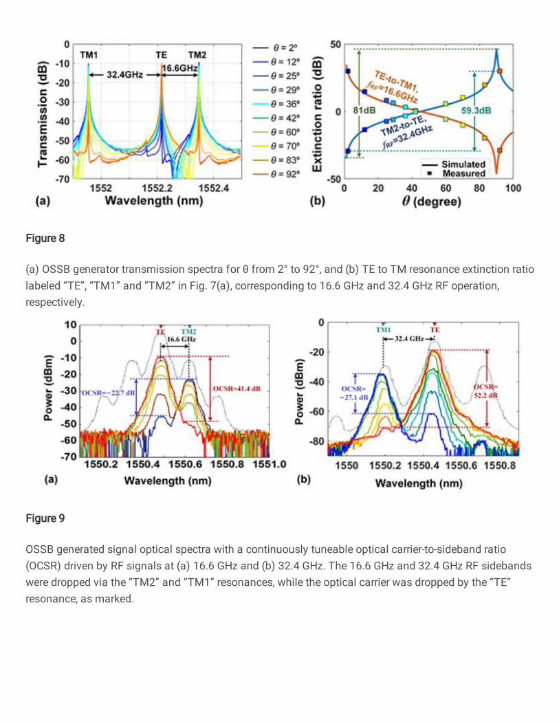
Figure 8
(a) OSSB generator transmission spectra for θ from 2° to 92°, and (b) TE to TM resonance extinction ratiolabeled “TE”, “TM1” and “TM2” in Fig. 7(a), corresponding to 16.6 GHz and 32.4 GHz RF operation,respectively.
Figure 9
OSSB generated signal optical spectra with a continuously tuneable optical carrier-to-sideband ratio(OCSR) driven by RF signals at (a) 16.6 GHz and (b) 32.4 GHz. The 16.6 GHz and 32.4 GHz RF sidebandswere dropped via the “TM2” and “TM1” resonances, while the optical carrier was dropped by the “TE”resonance, as marked.

Figure 10
Principle of operation of the RF photonic equalizer using dual-polarization-mode ring resonators. PD:photo-detector. PM: phase modulator. PC: polarization controller. DP-MRR: LD: laser diode. dual-polarization-mode micro-ring resonator. VNA: vector network analyzer.
Figure 11
RF transmission of a single passband with TM-polarized optical input.

Figure 12
RF transmission of the single passband with varying (a) carrier wavelength, (b) chip temperature, and (c)input optical power. (d−f) Extracted centre frequency and 3dB bandwidth.

Figure 13
RF transmission of the proposed equalizer with varying operation frequencies by tuning the (a) carrierwavelength and (c) chip temperature. (c) and (d) Extracted corresponding center frequencies of TE- andTM-passband.
Figure 14
(a) Transmission spectra of the optical through-port and drop-port of the DP-MRR and (b) RFtransmission of the equalizer with extinction ratio between TM and TE passbands as the input lightpolarization angle θ changes from 0º to 90º. fTM−fTE denotes the spacing between the TM-passbandand TE-passband, which is wideband tuneable (Fig. 12) and in this plot is 4.8 GHz
Figure 15

OP-OSSB (orthogonally polarized optical single sideband) generator schematic. LD: laser diode. OSA:optical spectrum analyzer. EOM: electro-optical modulator. VNA: vector network analyzer. DSB: doublesideband PC: polarization controller.. OPM: optical power meter. 45º POL: optical polarizer with thepolarization direction having an angle of 45º to the TM axis. PD: photodetector. RFG: RF generator.
Figure 16
Measured (a) transmission spectra of the 49GHz (TM) MRR, 200GHz FSR (TE) MRR, and the combinedOP-OSSB generator. (b) Zoom-in spectra of (a) with one TE polarized resonance and one TM polarizedresonance. (c) Transmission spectra around one TM-polarized resonance of the 49GHz FSR MRR.
Figure 17
Optical spectra of the generated orthogonally polarized OSSB signal.

Figure 18
Measured (a) transmission spectra of the dual MRRs and (b–c) optical spectra of the generatedorthogonally polarized OSSB signal with continuously tunable OCSR.
Figure 19
Measured (a) optical transmission spectra, and (b) RF transmission response of the OP-OSSB generatorwith thermo-optical control.
Figure 20

(a) Optical spectra and (b) extracted operation RF frequency of the generated OP-OSSB signals withthermal tuning.