photolab 7600 uv-vis - fagerberg · photolab® 7600 uv-vis safety ba77096e01 06/2015 9 2safety 2.1...
TRANSCRIPT

OPERATING MANUALba77096e01 06/2015
photoLab® 7600 UV-VIS
SPECTROPHOTOMETER

photoLab® 7600 UV-VIS
Copyright © Weilheim 2015, WTW GmbHReproduction in whole - or even in part - is prohibited without the express written permission of WTW GmbH, Weilheim.Printed in Germany.
The most current version of the present operating manual is available on the Internet at www.WTW.com.
2 ba77096e01 06/2015

photoLab® 7600 UV-VIS Contents
Contents
1 Overview . . . . . . . . . . . . . . . . . . . . . . . . . . . . . . . . . . . . . . 51.1 Overview of the instrument . . . . . . . . . . . . . . . . . . . . . . . 51.2 Keypad . . . . . . . . . . . . . . . . . . . . . . . . . . . . . . . . . . . . . . . 61.3 Display . . . . . . . . . . . . . . . . . . . . . . . . . . . . . . . . . . . . . . . 8
2 Safety . . . . . . . . . . . . . . . . . . . . . . . . . . . . . . . . . . . . . . . . 92.1 Safety information . . . . . . . . . . . . . . . . . . . . . . . . . . . . . . 9
2.1.1 Safety information in the operating manual . . . . . 92.1.2 Safety signs on the product . . . . . . . . . . . . . . . . . 92.1.3 Further documents providing safety information
92.2 Safe operation . . . . . . . . . . . . . . . . . . . . . . . . . . . . . . . . 10
2.2.1 Authorized use . . . . . . . . . . . . . . . . . . . . . . . . . 102.2.2 Requirements for safe operation . . . . . . . . . . . . 102.2.3 Unauthorized use . . . . . . . . . . . . . . . . . . . . . . . 10
2.3 User qualification . . . . . . . . . . . . . . . . . . . . . . . . . . . . . . 102.4 Handling of hazardous substances . . . . . . . . . . . . . . . . 11
3 Commissioning . . . . . . . . . . . . . . . . . . . . . . . . . . . . . . . 123.1 General notes on handling . . . . . . . . . . . . . . . . . . . . . . . 123.2 Initial commissioning . . . . . . . . . . . . . . . . . . . . . . . . . . . 12
3.2.1 Inserting the buffer batteries . . . . . . . . . . . . . . . 133.2.2 Connecting the power supply . . . . . . . . . . . . . . 133.2.3 Switching on the photometer and setting the
language . . . . . . . . . . . . . . . . . . . . . . . . . . . . . . 143.2.4 Set the date and time . . . . . . . . . . . . . . . . . . . . 15
4 Operation . . . . . . . . . . . . . . . . . . . . . . . . . . . . . . . . . . . . 164.1 Switching on or off the photometer . . . . . . . . . . . . . . . . 164.2 General operating principles . . . . . . . . . . . . . . . . . . . . . 18
4.2.1 Navigating with function keys and menus . . . . . 184.2.2 Display of navigation paths in short form . . . . . 194.2.3 Entry of numerals, letters and characters . . . . . 21
4.3 Zero adjustment . . . . . . . . . . . . . . . . . . . . . . . . . . . . . . . 224.4 Measuring in Concentration mode . . . . . . . . . . . . . . . . . 26
4.4.1 Measuring cell tests with barcode . . . . . . . . . . . 264.4.2 Measuring reagent tests with AutoSelector . . . . 27
4.5 Measuring the Absorbance / % Transmission . . . . . . . . 294.5.1 General information . . . . . . . . . . . . . . . . . . . . . . 29
3ba77096e01 06/2015

Contents photoLab® 7600 UV-VIS
4.5.2 Measuring the absorbance or transmission . . . .29
5 Maintenance and cleaning . . . . . . . . . . . . . . . . . . . . . . .315.1 Exchanging the buffer batteries . . . . . . . . . . . . . . . . . . . .315.2 Cleaning . . . . . . . . . . . . . . . . . . . . . . . . . . . . . . . . . . . . . .32
5.2.1 Cleaning the enclosure . . . . . . . . . . . . . . . . . . . .325.2.2 Cleaning the cell shaft . . . . . . . . . . . . . . . . . . . . .325.2.3 Cleaning the detector lens . . . . . . . . . . . . . . . . .33
6 What to do if ... . . . . . . . . . . . . . . . . . . . . . . . . . . . . . . . .346.1 Actions in the case of a broken cell . . . . . . . . . . . . . . . . .346.2 Error causes and remedies . . . . . . . . . . . . . . . . . . . . . . .35
7 Technical data . . . . . . . . . . . . . . . . . . . . . . . . . . . . . . . . .387.1 Measurement characteristics . . . . . . . . . . . . . . . . . . . . . .387.2 Measured value documentation and quality assurance . .417.3 General meter data . . . . . . . . . . . . . . . . . . . . . . . . . . . . .41
4 ba77096e01 06/2015

photoLab® 7600 UV-VIS Overview
1 Overview
1.1 Overview of the instrument
Front of theinstrument
Socket field on therear panel
1 Display2 Keypad3 Shaft for rectangular cells4 Turn-up lid5 Shaft for round cells6 Cell shaft cover
Fig. 1-1 Front of the instrument with operating elements
2
1
3 5
6
4
7 Connection for power pack8 Ethernet connection9 USB-A connection10 USB-B connection
Fig. 1-2 Rear panel with socket field
All connections comply with SELV.
78
9 10
5ba77096e01 06/2015

Overview photoLab® 7600 UV-VIS
1.2 Keypad
Overview
Key functions The keys on the right side of the keypad have the following functions:
1 Function keys F1 to F4 (function menu-depending)2 Alphanumeric keypad3 Keys with dedicated function
Fig. 1-3 Keypad
1
2 3
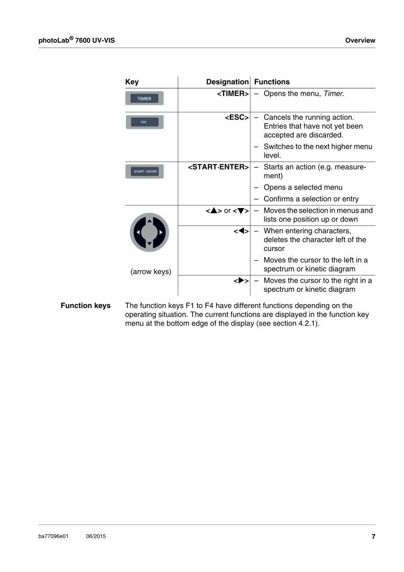
Key Designation Functions
<ON/OFF> – Switches the photometer on and off
<HOME> – Switches to the main menu from any operating situation. Actions that are not completed are can-celed.
<PRINT> – Outputs the displayed measured value to an interface if thePrinter symbol is displayed in the status line.
<STORE> – Saves a displayed measured value or spectrum if the Save symbol is displayed in the status line.
<ZERO·BLANK> – Starts one of the following mea-surements, depending on the operating situation:- Zero adjustment- Blank value measurement- Baseline measurement- User calibration
6 ba77096e01 06/2015
photoLab® 7600 UV-VIS Overview
Function keys The function keys F1 to F4 have different functions depending on the operating situation. The current functions are displayed in the function key menu at the bottom edge of the display (see section 4.2.1).
<TIMER> – Opens the menu, Timer.
<ESC> – Cancels the running action. Entries that have not yet been accepted are discarded.
– Switches to the next higher menu level.
<START·ENTER> – Starts an action (e.g. measure-ment)
– Opens a selected menu
– Confirms a selection or entry
(arrow keys)
<> or <> – Moves the selection in menus and lists one position up or down
<> – When entering characters, deletes the character left of the cursor
– Moves the cursor to the left in a spectrum or kinetic diagram
<> – Moves the cursor to the right in a spectrum or kinetic diagram
Key Designation Functions
7ba77096e01 06/2015

Overview photoLab® 7600 UV-VIS
1.3 Display
Display element
Symbols in thestatus line
1 Status line (current state, date and time)2 Display range for menus and measurement results3 Function keys menu
Fig. 1-4 Display
1
2
3
Concentration 16.01.15 9:52
1.92 mg/l
18: 14752 NH4-N
10 mm 0.05 - 3.00 mg/l
Setup Method list Citation form Unit
Symbol Designation Function
Save The <STORE> key is active.You can store the displayed data with <STORE>.
Printer The <PRINT> key is active.You can output to an interface the displayed data with <PRINT>.
8 ba77096e01 06/2015

photoLab® 7600 UV-VIS Safety
2 Safety
2.1 Safety information
2.1.1 Safety information in the operating manual
This operating manual provides important information on the safe operation of the product. Read this operating manual thoroughly and make yourself familiar with the product before putting it into operation or working with it. The operating manual must be kept in the vicinity of the product so you can always find the information you need.
Important safety instructions are highlighted in this operating manual. They are indicated by the warning symbol (triangle) in the left column. The signal word (e.g. "CAUTION") indicates the level of danger:
WARNINGindicates a possibly dangerous situation that can lead to serious (irre-versible) injury or death if the safety instruction is not followed.
CAUTIONindicates a possibly dangerous situation that can lead to slight (revers-ible) injury if the safety instruction is not followed.
NOTEindicates a situation where goods might be damaged if the actions mentioned are not taken.
2.1.2 Safety signs on the product
Note all labels, information signs and safety symbols on the product. A warn-ing symbol (triangle) without text refers to safety information in this operating manual.
2.1.3 Further documents providing safety information
The following documents provide additional information, which you should observe for your safety when working with the measuring system:
Operating manuals of other components of the photoLab® 7600 UV-VIS (accessories)
Safety datasheets for chemicals.
9ba77096e01 06/2015

Safety photoLab® 7600 UV-VIS
2.2 Safe operation
2.2.1 Authorized use
The authorized use of the photometer consists exclusively of the carrying out of photometric measurements according to this operating manual. Follow the technical specifications of the cells in chapter 7 TECHNICAL DATA. Any other use is considered unauthorized.
2.2.2 Requirements for safe operation
Note the following points for safe operation:
The product may only be operated according to the authorized use spec-ified above.
The product may only be supplied with power by the energy sources men-tioned in this operating manual.
The product may only be operated under the environmental conditions mentioned in this operating manual.
The product may not be opened.
2.2.3 Unauthorized use
The product must not be put into operation if:
it is visibly damaged (e.g. after being transported)
it was stored under adverse conditions for a lengthy period of time (storing conditions, see chapter 7 TECHNICAL DATA).
2.3 User qualification
Carrying out photometric determinations with the aid of test sets frequently requires the handling of hazardous substances.
We assume that the operating personnel know how to handle hazardous sub-stances due to their professional training and experience. The operating per-sonnel must particularly be able to understand and correctly implement the safety labels and safety instructions on the packages and inserts of the test sets.
10 ba77096e01 06/2015

photoLab® 7600 UV-VIS Safety
2.4 Handling of hazardous substances
When developing test sets, WTW carefully sees that the tests can be carried out as safely as possible. Some hazards by dangerous substances, however, cannot always be avoided.
If self-produced tests or solutions are used, the responsibility concerning any risks caused by those tests or soulutions lies with the user (personal respon-sibility).
WARNINGImproper handling of certain reagents can cause damage to your health. In any case follow the safety labels on the packing and the safety in-structions of the package insert. Protective measures specified there have to be followed exactly.
Safety datasheets The safety datasheets of the chemicals comprise all instructions on safe han-dling, occurring hazards, preventive actions and actions to take in hazardous situations. Follow these instructions in order to work safely.
11ba77096e01 06/2015

Commissioning photoLab® 7600 UV-VIS
3 Commissioning
3.1 General notes on handling
The photoLab® 7600 UV-VIS photometer is an optical precision meter. Therefore, it should always be handled with care, especially in mobile use. Always protect the meter from conditions that could damage the mechanical, optical and electronic components. Heed the following points especially:
The temperature and humidity during operation and storage must be within the limits specified in chapter 7 TECHNICAL DATA.
The following influences always have to be avoided with the meter:
– Extreme dust, moisture and wetness
– Exposure to intensive light and heat
– Fumes that are corrosive or contain high concentrations of solvents.
For measuring, the meter must be placed on a flat surface.
Spilled liquid or other material should be removed immediately (see sec-tion 5.2 CLEANING).
If a cell has broken in the cell shaft, the cell shaft should be cleaned imme-diately (see section 6.1 ACTIONS IN THE CASE OF A BROKEN CELL).
The cell shaft should always be closed when the photometer is not used.
During transport of the photometer, the cell shaft has to be empty.
For mobile use we recommend the transport case.
3.2 Initial commissioning
Perform the following activities:
Insert the buffer batteries (see section 3.2.1)
Connect the power supply (see section 3.2.2)
Switch on the photometer (see section 3.2.3)
Set the language (see section 3.2.3)
Set the date and time (see section 3.2.4)
Carry out zero adjustment (see section 4.3)
Packing This photometer is sent out in a protective transport packing.
CAUTIONKeep the original packing including the inner packing to protect the in-strument against hard shocks if it has to be transported. The original packing is also required for the proper return of the instru-
12 ba77096e01 06/2015

photoLab® 7600 UV-VIS Commissioning
ment if it has to be repaired.Note that damage caused by improper transport voids all warranty claims.
3.2.1 Inserting the buffer batteries
The buffer batteries supply the integrated clock while the photometer is switched off. Four alkaline manganese batteries (type AA or Mignon) separately included in the scope of delivery are used as the buffer batteries.
Insert the batteries as follows:
3.2.2 Connecting the power supply
The power is supplied via the enclosed plug-in power pack. The power pack supplies the photometer with low voltage (12 VDC).
CAUTIONThe line voltage of the usage location must fulfill the specifications stat-ed on the power pack (the specifications are also given in chapter 7 TECHNICAL DATA). Always use the supplied 12 V original power pack on-ly. Before plugging in the power cable check whether it is undamaged. If the power cable is damaged, the instrument must not be operated.
1 Turn the photometer upside down and place it on a soft surface.
2 Open the lid of the battery compartment (1).
3 Insert the four batteries in the battery compartment. Make sure that the poles of the batteries are in the correct position. The ± signs on the batteries must correspond to the ± signs in the battery compartment.
4 Close the lid of the battery compartment.
1
13ba77096e01 06/2015

Commissioning photoLab® 7600 UV-VIS
Connecting theplug-in power pack
3.2.3 Switching on the photometer and setting the language
During the initial commissioning the photometer automatically guides you to the setting of the meter language after switching on (<ON/OFF>).
After the initial commissioning, you can change the language in the General setup / Language menu at any time.
1 Connect the miniplug of the power pack to the socket (1) of the pho-tometer.
2 Connect the plug-in power supply unit to an easily accessible mains socket.
The display illumination switches itself on and then off again.
1 Select a language with <><>.
2 Confirm the selected language with <START·ENTER>.
The language has been set.The currently selected language is marked by a tick.
The display switches to the setting of Date and Time.
1
General setup 16.01.15 9:52
German
English Français Español ItalianoBulgarian/БългарскиČeskoSimplified Chinese/ 中Traditional Chinese/ 繁Greek/Ελληνικά
14 ba77096e01 06/2015
photoLab® 7600 UV-VIS Commissioning
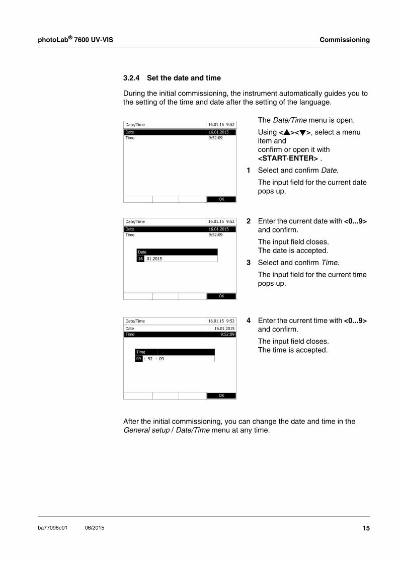
3.2.4 Set the date and time
During the initial commissioning, the instrument automatically guides you to the setting of the time and date after the setting of the language.
After the initial commissioning, you can change the date and time in the General setup / Date/Time menu at any time.
The Date/Time menu is open.
Using <><>, select a menu item and confirm or open it with <START·ENTER> .
1 Select and confirm Date.
The input field for the current date pops up.
2 Enter the current date with <0...9> and confirm.
The input field closes.The date is accepted.
3 Select and confirm Time.
The input field for the current time pops up.
4 Enter the current time with <0...9> and confirm.
The input field closes.The time is accepted.
Date/Time 16.01.15 9:52
Date 16.01.2015Time 9:52:09
OK
Date/Time 16.01.15 9:52
Date 16.01.2015Time 9:52:09
OK
Date
16 .01.2015
Date/Time 16.01.15 9:52
Date 16.01.2015Time 9:52:09
OK
Time
09 : 52 : 09
15ba77096e01 06/2015

Operation photoLab® 7600 UV-VIS
4 Operation
4.1 Switching on or off the photometer
Switching on
Starting theSelf test
Self test During the self-test, all cells must be removed and the cell shaft cover closed. The self-test runs in the background and may take some minutes.
1 Switch the photometer on with <ON/OFF>.
The display shows
– the Self test dialog (if the user management is not active).
or
– the Login dialog(if the user management is active).
With activated user management:
2 Login
Enter user name and password or log in as a guest.
Then the Self test dialog is displayed.
Self test 16.01.15 9:52
Please make sure no cell is inserted and the cover is closed.
Then press <START/ENTER>
Setup Info
Login 16.01.15 9:52
Enter user name
Administrator
3 Remove all cells and close the cell shaft cover.
4 Start the self-test with <START·ENTER>.
The photometer carries out the self-test.
Self test 16.01.15 9:52
Please make sure no cell is inserted and the cover is closed.
Then press <START/ENTER>
16 ba77096e01 06/2015

photoLab® 7600 UV-VIS Operation
Switching off To switch the photometer off, keep the <ON/OFF> key depressed until the photometer is switched off.
The self-test includes:
– the test of the memory, processor, internal interfaces, filter and lamp
– a calibration for each wavelength
After the self-test is completed, the main menu is displayed.
The result of the self-test can be viewed and printed with the [Info] function key.
Self test 04/16/07 9:52
System test
System testFilter testLamp testWavelength calibration
17ba77096e01 06/2015

Operation photoLab® 7600 UV-VIS
4.2 General operating principles
4.2.1 Navigating with function keys and menus
The current menu selection is displayed in reverse video. The assignment of the function key menu is adapted to the current operating situation. The functions of the function key menu are started with the function keys (F1 ... F4).
Press the function key <F1> ([Setup]).The General setup submenu pops up.
Press the <><> <><> key.
The menu selec-tion moves in the corresponding direction.
To navigate further, use <><> <><> and <START·ENTER>
Press the <START·ENTER> key.This has confirmed the current selection. A new menu pops up.
Further navigation with function keys (here: F1 and F2)
General setup 16.01.15 9:52
LanguageDate/Time
Display settings
User management
Measured value memory
Software/methods update
Reset
Data transfer/Printer
Exchange methods/profiles
Save all data on USB memory
Unlock application packages
Concentration 16.01.15 9:52
Please select method for measuring or insert a barcoded cell
or insert AutoSelector.
Setup Method list Last method New Method
<F1>
<><><><>
<START·ENTER>
18 ba77096e01 06/2015

photoLab® 7600 UV-VIS Operation
Use of the functionkeys
The function keys F1 to F4 are below the display. Their functions change depending on the operating situation and mode. The current functions are displayed in the function key menu at the bottom edge of the display.
Apart from navigation, the function keys are also used for other operations:
Opening a selection list or input field
Executing a command (directly or with intermediate query)
Switch over between two display options, such as absorbance transmission
Navigation witharrow keys
(<><>) and<START·ENTER>
These operating elements are used to select an item from a menu or list. The current selection is displayed in reverse video. Pressing of <START·ENTER> confirms the selection.
Apart from navigation, the <START·ENTER> key is also used for other operations:
Opening a selection list or input field
Confirming a selection
Confirming entries of text and numerals
Executing a command (directly or with intermediate query)
Activating an item in a selection list ( = active)
4.2.2 Display of navigation paths in short form
In this operating manual, the introductory navigation steps leading to individual menus or dialogs are clearly shown in a gray box. The box indicates a section of the menu tree.
Starting point of the description is always the main menu, which can be reached with the <HOME> key from any operating situation. From there navigation takes place downward.
19ba77096e01 06/2015

Operation photoLab® 7600 UV-VIS
Operating example:Navigation to the
setting menu for thelanguage
The following example shows the elements of the menu tree with the relevant operating steps:
Further navigation options:
The <ESC> key moves you one level up in the menu tree.
The <HOME> key directly calls up the main menu.
If you are "lost" in a menu, press <HOME> and restart navigating from the main menu.
<HOME>[General setup]
– Language
Bold letters and angle brackets indicate a key on the photometer (except function keys).
→ Press the "Home" key. The main menu is called up.
Square brackets in this operating manual indicate a function key F1 to F4. The text between the brackets corresponds to the assignment according to the function key menu on the bottom edge of the display.
→ Press the function key with the assignment "Settings"
Text without brackets stands for a menu item indicated on the display (list item).
→ Select the menu item with the arrow keys <><>. The current selection is displayed in reverse video.
→ Then press <START·ENTER>.
20 ba77096e01 06/2015

photoLab® 7600 UV-VIS Operation
4.2.3 Entry of numerals, letters and characters
Numerals, letters, punctuation marks and special characters are entered with the alphanumeric keypad of the meter or using an external keyboard.
The numerals and characters (expect for the small letters) assigned to the keys of the alphanumeric keypad are printed on the keys. Example: With the <7/PQRS> key you can enter the following characters: 7, P, Q, R, S, p, q, r, s.
Select the required character by pressing the key several times (similar to a mobile phone). When pressing a key that is assigned to several characters once, the respective numeral appears first. To enter a numeral, one keypressing is always sufficient.
When pressing the key for the first time a line pops up that displays all characters possible with this key. The currently selected character is highlighted.
A character is taken over in the input field if
the character is highlighted for more than one second,
the character is confirmed with <START·ENTER>,
another alphanumeric key is pressed.
Special characters Special characters are entered with the <1/*> key.
Operating example:Entering the ID
The Enter ID input field appears if you press the <STORE> key while the storing symbol is visible. In the following example a measurement dataset with the ID "Test" is stored.
Correcting incorrectentries
Using <>, erase all characters until you have reached the incorrect digit and repeat the entry from there.
1 Press <8/TUV> several times until "T" appears in the input line.
Below the input field, a selection line pops up with all characters that are available for this key, e.g. 8 T U V t u v.The currently selected character is highlighted.
After approx. one second the character is taken over and the selection line closed.
2 Complete the ID with <A...9> and confirm.
Enter ID
88 T U V t u v
Enter ID
T8 T T U V t u v
Enter ID
Test_
21ba77096e01 06/2015

Operation photoLab® 7600 UV-VIS
4.3 Zero adjustment
A valid zero adjustment is required for the calculation of measured values in the modes, Concentration, Absorbance / % Transmission, Multi wavelengths and Kinetics. With a zero adjustment, the absorbance of a cell filled with dis-tilled water ("zero cell") is measured and stored.
Factory zeroadjustment forconcentration
measurements
For all measurements with WTW test sets (Concentration mode), a factory zero adjustment is available in the delivery condition. We recommend replacing it with a zero adjustment of your own. If a zero adjustment exists already for a method, the date and time of the last zero adjustment are displayed in the top right area of the display.
Zero adjustment forabsorbance
measurements
In the Absorbance mode, the zero adjustment has to be carried out sepa-rately for each cell type and each used wavelength. If a zero adjustment exists already for the inserted cell type at the selected wavelength, the date and time of the last zero adjustment are displayed in the top right area of the display.
If no zero adjustment is available, the photometer will prompt you to carry out a zero adjustment.
Concentration 16.01.15 9:52
[ZERO 15.01.15 11:11]
Please select method for measuring or insert a barcoded cell
or insert AutoSelector.
Setup Method list Last method New Method
The cells must be absolutely clean and free of scratches.Always use a cell of the same type for zero adjustment and measurement of the sample.
Absorbance 16.01.15 9:52
[ZERO 15.01.15 11:11]
To start measurement,insert cell or press <Start/Enter>
525 nm 10 mm
Setup Wavelength Transmission Reference
22 ba77096e01 06/2015

photoLab® 7600 UV-VIS Operation
Notes on zeroadjustment
Zero adjustment with round cells:
Only use clean, scratch-free round cells with distilled water. The minimum filling level is 20 mm. A ready zero cell is included in the scope of delivery of the photometer and PhotoCheck.
A ready zero cell can, in principle, be used any number of times. We recommend, however, to regularly check the zero cell for visible contamination and scratches and refill or exchange it if necessary (at least every 24 months).
Zero adjustment with rectangular cells:
For rectangular cells, the zero adjustment must be carried out with the same cell type (manufacturer and cell material [e.g. optical glass, quartz glass, plastic]) that is used for measurement. This is important because cells of different manufacturers have a different absorption behavior. When changing the cell type repeat the zero adjustment with the new type.
Prior to zero adjustment, clean the rectangular cell and fill it with distilled water. The minimum filling level is 20 mm.
Rectangular cells always have to be inserted in the cell shaft with the same orientation for measurement and zero adjustment (e.g. cell printing on the left side).
Carrying out a zeroadjustment
The zero adjustment takes place similarly in the Concentration, Absorbance / % Transmission, Multi wavelengths and Kinetics modes.
General requirements of the cells are given in chapter 7 TECHNICAL DATA. Note that the spectral transparency of the cell must be suitable for the intended application (example, quartz cell for UV range).
1 In the respective mode, press the <ZERO·BLANK> key.
2 In Concentration mode only:
Select and confirm Zero adjustment.
Concentration 16.01.15 9:52
3: A6/25 NH4-N
16 mm 0.20 - 8.00 mg/l
Setup Method list Citation form Unit
Adjust
Zero adjustment
Reagent blank value
Calibrate the method
23ba77096e01 06/2015

Operation photoLab® 7600 UV-VIS
The zero adjustment window pops up.
3 Close the inner turn-up lid.
4 Depending on the cell type, insert the zero cell as follows:
Round cell:
Insert the round cell in the round cell shaft so it touches the bottom.
If the inner turn-up lid is opened too wide, a message prompts you to close the inner turn-up lid.
Rectangular cell:
Open the inner turn-up lid.
Insert the rectangular cell vertically so it touches the bottom and left edge of the cell shaft. The opaque sides of the rectangular cell must point to the front and back.
The photometer has an external light recognition. If there is too much external light, a message prompts you to close the cell shaft cover.
The photometer automatically starts the zero adjustment and subsequently stores the value.
5 After a successful zero adjustment switch to measurement with [OK].
Zero adjustment 04/16/07 9:52
Please insert zero cell (distilled water)or press <Start/Enter>
Zero cell(H O dist.)2
innerturn-up lid
Zero cell(H O dist.)2
Zero adjustment 16.01.15 9:52
Zero adjustment successful
10 mm
OK
24 ba77096e01 06/2015

photoLab® 7600 UV-VIS Operation
Validity of the zeroadjustment
The data of the zero adjustment is stored in the photometer separately for each cell type. As long as the data is valid, it is automatically used again after a temporary change to a different cell type. The validity depends on the respective mode:
* After the wavelength or method respectively was temporarily exited thephotometer displays that a zero adjustment is available and the time it wascarried out. You can then decide whether to use this zero adjustment or carryout a new zero adjustment.
When to repeat thezero adjustment?
We recommend to repeat the zero adjustment in the following cases:
If the photometer was subject to mechanical stress such as strong shock or transport
If the ambient temperature changed by more than 5 °C since the last zero adjustment
At least once per week
If a new cell type (different manufacturer, different glass type is used)
Basically each time you want to measure with the highest possible accuracy.
Mode Validity of the zero adjustment
Concentration (permanently programmed methods)
Till the next zero adjustment
Absorbance / % Transmission Till the next zero adjustment with the same wavelength *
Concentration (user-defined methods) and Multi wavelengths
Till the next zero adjustment for the same method *
Kinetics Till another kinetic profile is loaded
Till the Kinetics mode is exited or the photometer is switched off
25ba77096e01 06/2015

Operation photoLab® 7600 UV-VIS
4.4 Measuring in Concentration mode
4.4.1 Measuring cell tests with barcode
Inserting a cell with barcode starts a measurement.
If a cell without barcode is used: Select a method.
1 Open the cell shaft cover.
2 Close the inner turn-up lid.
If the inner turn-up lid is opened too wide, a message prompts you to close the inner turn-up lid.
3 Insert the barcoded round cell in the round cell shaft so it touches the bottom. When doing so, align the line mark with the notch at the front of the round cell shaft.
The photometer selects the method with the aid of the barcode and starts measuring automatically.
4 Further options:
– Select a different citation form with [Citation form],(e.g. NH4 <–> NH4-N).
– Select a different measuring unit with [Unit],(e.g. mg/l <–> mmol/l).
– Make further settings such as dilution or blank value measurements with [Setup].
<HOME>Concentration
Concentration 16.01.15 9:52
Please select method for measuring or insert a barcoded cell
or insert AutoSelector.
Setup Method list Last method New Method
Line markBarcode
Concentration 16.01.15 9:52
49 mg/l
18: C3/25 (445 nm) COD
16 mm 10 - 150 mg/l
Setup Method list Citation form Unit
26 ba77096e01 06/2015

photoLab® 7600 UV-VIS Operation
4.4.2 Measuring reagent tests with AutoSelector
1 Open the cell shaft cover.
2 Insert the AutoSelector in the round cell shaft so it touches the bottom. When doing so, align the line mark with the notch at the front of the round cell shaft.
– The photometer selects the correct method with the aid of the barcode.
<HOME>Concentration
Concentration 16.01.15 9:52
Please select method for measuring or insert a barcoded cell or insert AutoSelector.
Setup Method list Last method New Method
Line markBarcode
Innerturn-up lid
27ba77096e01 06/2015
Operation photoLab® 7600 UV-VIS
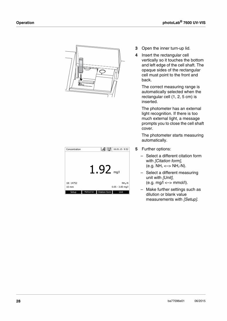
3 Open the inner turn-up lid.
4 Insert the rectangular cell vertically so it touches the bottom and left edge of the cell shaft. The opaque sides of the rectangular cell must point to the front and back.
The correct measuring range is automatically selected when the rectangular cell (1, 2, 5 cm) is inserted.
The photometer has an external light recognition. If there is too much external light, a message prompts you to close the cell shaft cover.
The photometer starts measuring automatically.
5 Further options:
– Select a different citation form with [Citation form],(e.g. NH4 <–> NH4-N).
– Select a different measuring unit with [Unit],(e.g. mg/l <–> mmol/l).
– Make further settings such as dilution or blank value measurements with [Setup].
Concentration 16.01.15 9:52
1.92 mg/l
18: 14752 NH4-N
10 mm 0.05 - 3.00 mg/l
Setup Method list Citation form Unit
28 ba77096e01 06/2015

photoLab® 7600 UV-VIS Operation
4.5 Measuring the Absorbance / % Transmission
4.5.1 General information
The absorbance or transmission respectively is measured without the use of any methods or profiles. All settings are configured during measurement.
Measuring againstthe Reference
absorbance
The absorbance or transmission can alternatively be measured against the absorbance of the zero adjustment or against a Reference absorbance determined by yourself.
4.5.2 Measuring the absorbance or transmission
The settings of the last measurement are active.
1 Using [Wavelength], change the wavelength as necessary.
2 Using [Absorbance] <–> [Transmission], you can switch over between absorbance and transmission measurement.
3 If necessary, use a reference measurement with [Reference] or measure a new one.
4 Depending on the type, insert the cell as follows:
Round cell:
Insert the round cell in the round cell shaft so it touches the bottom.
If the inner turn-up lid is opened too wide, a message prompts you to close the inner turn-up lid.
<HOME>Absorbance / % Transmission
Absorbance 16.01.15 9:52
To start measurement,insert cell or press <Start/Enter>
300 nm
Setup Wavelength Transmission Reference
innerturn-up lid
29ba77096e01 06/2015

Operation photoLab® 7600 UV-VIS
Rectangular cell:
Open the inner turn-up lid.
Insert the rectangular cell vertically so it touches the bottom and left edge of the cell shaft. The opaque sides of the rectangular cell must point to the front and back.
The photometer has an external light recognition. If there is too much external light, a message prompts you to close the cell shaft cover.
The photometer starts measuring automatically.
5 Using [Absorbance] <–> [Transmission], switch over the display from Absorbance to Transmission or vice versa as necessary.
Absorbance 16.01.15 9:52
0.860489 nm 10 mm
Setup Wavelength Transmission Reference
Transmission 16.01.15 9:52
13.8 %
489 nm 10 mm
Setup Wavelength Absorbance Reference
30 ba77096e01 06/2015

photoLab® 7600 UV-VIS Maintenance and cleaning
5 Maintenance and cleaning
5.1 Exchanging the buffer batteries
CAUTIONThere is a risk of explosion if unsuitable batteries are used. Only use leakproof alkaline manganese batteries.
Battery service life The power consumption of the clock is very low. The lifetime of high quality batteries is at least 5 years.
Disposal ofbatteries
Dispose of the batteries at a suitable facility according to local legal requirements. It is illegal to dispose of the batteries with household refuse.
Within the European Union, the batteries are removed at a specialized treatment center at the instrument's end of life. The instruments are taken to one of those specialized treatment centers via the recycling system set up for this purpose.
If you leave the photometer switched on during the exchange or insert the new batteries within a minute after taking out the old ones, the date and time are retained in the photometer.
1 Turn the photometer upside down and place it on a soft surface.
2 Open the lid of the battery compartment (1).
3 Remove the old batteries from the battery compartment.
4 Insert the four new batteries in the battery compartment. Make sure that the poles of the batteries are in the correct position. The ± signs on the batteries must correspond to the ± signs in the battery compartment.
5 Close the lid of the battery compartment.
1
31ba77096e01 06/2015

Maintenance and cleaning photoLab® 7600 UV-VIS
5.2 Cleaning
Especially after a cell has broken or after a reagents accident, the photometer should immediately be cleaned (see also section 6.1 ACTIONS IN THE CASE OF A BROKEN CELL).
5.2.1 Cleaning the enclosure
NOTEThe housing components are made out of synthetic materials (ABS, PMMA and PC). Thus, avoid contact with acetone, ethyl alcohol and similar deter-gents that contain solvents. Remove any splashes immediately.
Clean the photometer enclosure as follows:
If the housing surface is dirty, wipe it with a soft cloth and mild soapy water.
Remove any chemicals splashes as soon as possible.
For disinfection, you can use isopropanol for cleaning for a short time.
5.2.2 Cleaning the cell shaft
NOTEThe housing components are made out of synthetic materials (ABS, PMMA and PC). Thus, avoid contact with acetone, ethyl alcohol and similar deter-gents that contain solvents. Remove any splashes immediately.
Normally, it is not required to clean the cell shaft routinely. Remove dust and slight contamination with a moist, lint free cloth. Use isopropanol briefly to remove persistent coatings (e.g. reagent remains). Especially clean the bot-tom parts of the lateral surfaces of the rectangular cell shaft where the light barriers for the automatic cell recognition are located.
If a cell has broken, the cell shaft has to be cleaned immediately. To do so, proceed as described in section 6.1.
32 ba77096e01 06/2015

photoLab® 7600 UV-VIS Maintenance and cleaning
5.2.3 Cleaning the detector lens
Normally, it is not required to clean the detector lens routinely. Cleaning the detector lens can be necessary in the following cases:
If the lens is visibly smudged, e.g. after a cell has broken or after a reagent accident (see also section 6.1 ACTIONS IN THE CASE OF A BROKEN CELL).
If, due to environmental influences or reagent contamination, the photo-meter displays the message, Wavelength calibration during the self-test after being switched on (see section 6.2)
Proceed as follows to clean the detector lens:
If the lens is often smudged (error, Wavelength calibration during the self-test), check whether the correct operating conditions are observed. Follow the details in section 3.2 for this purpose.
The detector lens is on the front left side of the rectangular cell shaft (pos. 1).
1 Switch off the photometer.
2 Cut off one end of a customary cotton swab (approx. 2 cm).
3 Grasp the cut-off end with the tip of a pair of tweezers or small pli-ers. Clean the lens with the dry head of the cotton swab. To do so, move the head from the center of the lens outward in circles. If there are persistent coatings, moisten the cotton swab with a little deion-ized water or isopropanol.
After recommissioning, carry out the photometer monitoring for all measurements.
1
33ba77096e01 06/2015

What to do if ... photoLab® 7600 UV-VIS
6 What to do if ...
6.1 Actions in the case of a broken cell
WARNINGCells can contain dangerous substances. If the contents are released, follow the safety instructions of the package insert. If necessary, take corresponding protective measures (protective goggles, protective gloves etc.).
CAUTIONDo not turn the photometer upside down or laterally to remove the liq-uid! When doing so, the liquid could come into contact with electronic com-ponents and damage the photometer.
The photometer has a drain device through which the contents of a broken cell can drain off without causing any damage.
Proceeding after acell has broken
If, after recommissioning, an error occurs during the wavelength calibration,
1 Switch off the photometer and disconnect it from the power supply.
2 Let the liquid drain off into a suitable container and dispose of it properly according to the instructions of the reagent package.
3 Carefully remove all broken glass, e.g. with tweezers.
4 Carefully clean the cell shaft using a moist, lint-free cloth. If there are persistent coatings, use isopropanol for a short time. Especially clean the bottom parts of the lateral surfaces of the rectangular cell shaft, where the light barriers for the automatic cell recognition are located.
5 Let the cell shaft dry.
After recommissioning, carry out the photometer monitoring for all measurements.
34 ba77096e01 06/2015

photoLab® 7600 UV-VIS What to do if ...
the detector lens is probably smudged. In such a case, clean the lens as fol-lows:
Cleaning thedetector lens
6.2 Error causes and remedies
Instrument does notreact to keystroke
Acoustic signal onkeystroke
Measuring rangeundercut or
exceeded
The detector lens is on the front left side of the rectangular cell shaft (pos. 1).
1 Switch off the photometer.
2 Cut off one end of a customary cotton swab (approx. 2 cm).
3 Grasp the cut-off end with the tip of a pair of tweezers or small pli-ers. Clean the lens with the dry head of the cotton swab. To do so, move the head from the center of the lens outward in circles. If there are persistent coatings, moisten the cotton swab with a little deion-ized water or isopropanol.
1
Cause Remedy
– Operating condition undefined or EMC load unallowed
– Processor reset:Press the <ON/OFF> and <ESC> key simultaneously.
Cause Remedy
– The key does not have any function in the current operating state
– Press a different key
Cause Remedy
– Method not suitable – Select method with suitable measuring range
– Dilute the sample
35ba77096e01 06/2015

What to do if ... photoLab® 7600 UV-VIS
Self-test does notstart.
The instrumentdisplays
Please remove cell
Obviously incorrectmeasured values
Fluctuatingmeasured values
In Concentration mode you can display the current absorbance value as an additional information ([Setup]/Display absorbance).
Cause Remedy
– A cell is inserted in one of the cell shafts
– Remove the cell
– Then press the <START·ENTER> key
– A foreign object is inserted in one of the cell shafts
– Remove foreign object
– Then press the <START·ENTER> key
– Occasionally, the instrument car-ries out an automatic readjust-ment for the rectangular cell recognition. The informative mes-sage Please remove cell is dis-played even when no cell is inserted.
– Press the <START·ENTER> key.
– The cell shaft is contaminated – Clean the cell shaft (see section 5.2.2 and section 6.1)
– Restart the instrument
– If necessary, confirm the Please remove cell message with <START·ENTER>.
– Instrument defective – Please contact the service department.
Cause Remedy
– Cell contaminated – Clean the cell
– Dilution set incorrectly – Set the dilution
– Selected method not suitable – Select different method
– Zero measurement incorrect – Perform zero measurement
– Blank value incorrect – Remeasure the blank value
Cause Remedy
– Cell shaft cover open – Close the cell shaft cover
36 ba77096e01 06/2015

photoLab® 7600 UV-VIS What to do if ...
Self test failed.
Connected printerdoes not print
Data transmissionto USB memorydevice does not
work
Cause Remedy
– System test: Instrument defective – Please contact the service department.
– Filter test: Instrument defective – Please contact the service department.
– Wavelength calibration:
– Foreign particle in the cell shaft
– Lens smudged
– Instrument defective
– Remove foreign object
– Clean the lens (see section 5.2.3 or section 6.1). If this happens repeatedly, check the operating conditions (see section 3.1)
– Please contact the service department.
Cause Remedy
– Printer not suitable – Connect a printer that can interpret the printer control language PCL-3
Cause Remedy
– Connected USB memory device was not recognized
– The USB memory device has been formatted to a file system which is not supported, e. g. NTFS
– Use other USB memory device
– Format the USB memory device to the FAT 32 file system
37ba77096e01 06/2015

Technical data photoLab® 7600 UV-VIS
7 Technical data
7.1 Measurement characteristics
Measuring principle Spectrophotometer with reference beam technology
Light source Lamp type Xenon flashlamp
Average lifetime 5 x 10⁸ flashes, corresponding to at least 13000 h in permanent operation
Monochromator Type Grating monochromator with step motor
Wavelength range 190 - 1100 nm
Max. scan speed approx. 1000 nm/min
Wavelengths calibration Automatic
Accuracy ± 1 nm
Reproducibility ± 0.5 nm (checkable, e.g. with holmium oxide filter)
Resolution 1 nm
Spectral band width 4 nm
Photometricmeasurement
Light sensor Photo diode
Measuring range A = -3.300 to A = +3.300
Linearity < 1 % for A ≤ 2.000 in the range 340 to 900 nm
Accuracy * ± 0.003 A for A < 0.600
± 0.5 % of the reading for 0.600 ≤A≤ 2.000
Reproducibility * ± 0.002 at A = 1.000
Resolution ΔA = 0.001
Stray light < 0.05 % transmission at 340 and 408 nm
* in the range 200 nm ... 1000 nm
38 ba77096e01 06/2015
photoLab® 7600 UV-VIS Technical data
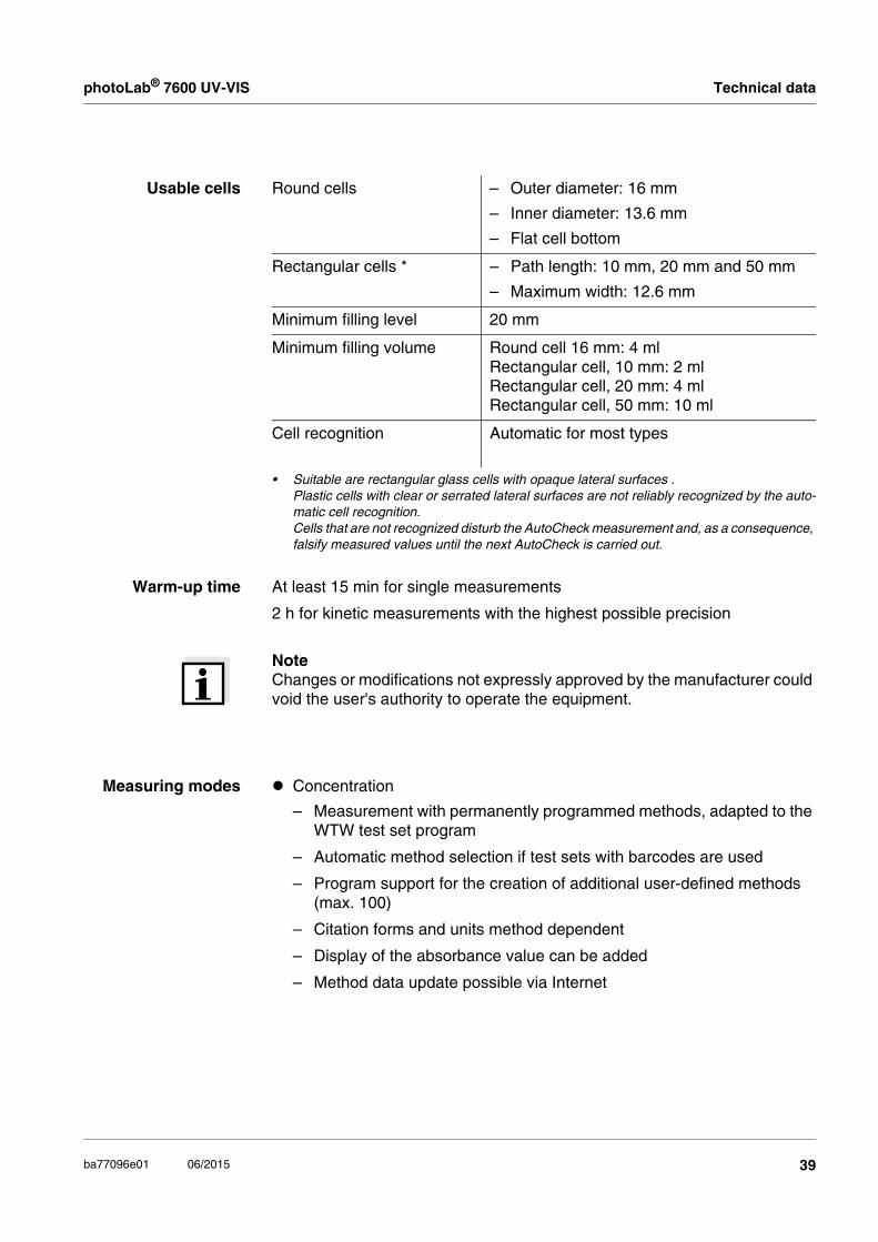
NoteChanges or modifications not expressly approved by the manufacturer could void the user's authority to operate the equipment.
Usable cells Round cells – Outer diameter: 16 mm
– Inner diameter: 13.6 mm
– Flat cell bottom
Rectangular cells * – Path length: 10 mm, 20 mm and 50 mm
– Maximum width: 12.6 mm
Minimum filling level 20 mm
Minimum filling volume Round cell 16 mm: 4 mlRectangular cell, 10 mm: 2 mlRectangular cell, 20 mm: 4 mlRectangular cell, 50 mm: 10 ml
Cell recognition Automatic for most types
• Suitable are rectangular glass cells with opaque lateral surfaces .Plastic cells with clear or serrated lateral surfaces are not reliably recognized by the auto-matic cell recognition.Cells that are not recognized disturb the AutoCheck measurement and, as a consequence, falsify measured values until the next AutoCheck is carried out.
Warm-up time At least 15 min for single measurements
2 h for kinetic measurements with the highest possible precision
Measuring modes Concentration
– Measurement with permanently programmed methods, adapted to the WTW test set program
– Automatic method selection if test sets with barcodes are used
– Program support for the creation of additional user-defined methods (max. 100)
– Citation forms and units method dependent
– Display of the absorbance value can be added
– Method data update possible via Internet
39ba77096e01 06/2015

Technical data photoLab® 7600 UV-VIS
Absorbance / % Transmission
– Measurement against own reference absorbance value possible
Multi wavelengths
– Freely definable calculations from absorbance values at up to 10 differ-ent wavelengths
– Calculations can be stored as methods (max. 499)
Measuring modes Spectrum
– Absorbance or % transmission mode
– Limits freely selectable within the wavelength range
– Increment: 1 nm
– Recording duration for the complete wavelength range: < 7 min
– Settings can be stored as profiles (max. 20)
– Evaluation functions: Cursor scanning, zoom, min./max. recognition, peak area determination, derivation, smoothing, multiplication by con-stants, addition of constants, addition and subtraction of spectra, for-mation of the quotient of two spectra
Kinetics
– Absorbance or % transmission mode
– Minimal adjustable scan interval: 1 s (if the absorbance of the test sam-ple is high, the scan interval is extended due to the longer duration of the individual measurements)
– Settings can be stored as profiles (max. 20)
– Evaluation functions: Cursor scanning, zoom, min./max. determination, slope calculation (for an interval or total), enzymatic activity
OptRF
– Measurement with permanently programmed methods for which no test sets are required
– Citation forms method dependent
40 ba77096e01 06/2015

photoLab® 7600 UV-VIS Technical data
7.2 Measured value documentation and quality assurance
7.3 General meter data
Memory formeasured values
Memory capacity – 5000 single measured values from the measuring modes: concentration, absorbance / % transmission and multi wavelengths
– 40 MByte internal memory, sufficient for approx. 500 spectra and 400 kinetic curves (sample values based on the following assumptions: All spectra over a wavelength range of 600 nm and all kinetic curves with 150 single values each)
Output options USB medium, printer, PC
File formats ASCII, *.csv
Monitoringfunctions
AQA1 Check of the photometer
AQA2 Check of the total system
AQA3 Check of the sample matrix
User management Can be switched off yes
User accounts 3 hierarchical levels (administrator, user, guest)
Password protection for administrators and users
Dimensions 404 x 197 x 314 mm (width x height x depth)
Weight approx. 4.5 kg (without plug-in power supply)
Housing type ofprotection
IP 30
Electricalprotective class
III
Test mark CE
41ba77096e01 06/2015

Technical data photoLab® 7600 UV-VIS
Allowedenvironmental
conditions
Temperature Operation: +10 °C to + 35 °C (41 °F to 95 °F)
Storage: -25 °C to + 65 °C (-13 °F to 268 °F)
Humidity Yearly mean: ≤ 75 %30 days/year: 95 %Other days: 85%
Climatic class 2
Powersupply
Power pack Type: EDACPOWER EA1036R
Input: 100 - 240 V ~ / 50 - 60 Hz / 1 A
Output: 12 V = / 3 A
Guidelinesand norms used
EMC EC directive 2004/108/EC
EN 61326-1
– Interference emission: Class B
– Interference immunity: IEC 61000-4-3
– Tolerance extension: 0.008 E
FCC Class A
Instrument safety EC directive 2006/95/ECEN 61010-1
Climatic class VDI/VDE 3540
IP protection EN 60529
Communicationinterfaces
Ethernet RJ45
USB – 1 x USB-A (for printer, USB media, keyboard or bar code reader)
– 1 x USB-B (for PC)
Other features Drain for spilled cell contents
Photometer software update and method data update possible via Internet
42 ba77096e01 06/2015


Wissenschaftlich-TechnischeWerkstätten GmbH
Dr.-Karl-Slevogt-Straße 1D-82362 WeilheimGermany
+49 881 183-0+49 881 [email protected]
Tel:Fax:E-Mail:Internet:
1) The tissue in plants that brings water upward from the roots;2) a leading global water technology company.
We're 12,500 people unified in a common purpose: creating innovative solutionsto meet our world's water needs. Developing new technologies that will improvethe way water is used, conserved, and re-used in the future is central to our work.We move, treat, analyze, and return water to the environment, and we help peopleuse water efficiently, in their homes, buildings, factories and farms. In more than150 countries, we have strong, long-standing relationships with customers whoknow us for our powerful combination of leading product brands and applicationsexpertise, backed by a legacy of innovation.
For more information on how Xylem can help you, go to www.xyleminc.com
Xylem | m|ˈ əzīl