phoenixbios4_rev6userman
TRANSCRIPT
5/14/2018 PhoenixBIOS4_rev6UserMan - slidepdf.com
http://slidepdf.com/reader/full/phoenixbios4rev6userman 1/88
Phoenix Technologies Ltd., 411 E. Plumeria, San Jose, CA 95134
Phoenix Technologies Ltd.
PhoenixBIOS 4.0Revision 6
User's Manual
5/14/2018 PhoenixBIOS4_rev6UserMan - slidepdf.com
http://slidepdf.com/reader/full/phoenixbios4rev6userman 2/88
Page ii Phoenix Technologies Ltd.
CopyrightPhoenixBIOS 4.0 User's Manual
22 June 2000
2000 Phoenix Technologies Ltd.
All Rights Reserved.
DisclaimerThe programs are provided "as is" without warranty of any kind either expressed
or implied, including but not limited to the implied warranties of merchantability
and fitness for a particular purpose. This publication could contain technical
inaccuracies or typographical errors. Changes are periodically made to the
information herein; these changes will be incorporated in new editions of this
publication. Phoenix Technologies Ltd. is without obligation to notify any
person of such revisions or changes.
Purpose of DocumentThis guide explains how to configure your PC and optimize its performance
using the Setup program. It also explains how to use the BIOS function calls in
writing computer programs.
PB4.0 UM 06.22.00
5/14/2018 PhoenixBIOS4_rev6UserMan - slidepdf.com
http://slidepdf.com/reader/full/phoenixbios4rev6userman 3/88
Phoenix Technologies, Ltd. Page iii
Contents About This Manual ......................................................................................1 Chapter 1The Setup Guide ......................................................................... 2
The Main Menu...................................................................................2 The Menu Bar .............................................................................3
The Legend Bar ..........................................................................3 The Field Help Window ..............................................................4 The General Help Window .........................................................4 Main Menu Selections ................................................................4 Master and Slave Sub-Menus ....................................................5 Memory Cache ...........................................................................7 Memory Shadow.........................................................................8 Boot Sequence ...........................................................................9 Keyboard Features ...................................................................10
Boot Menu......................................................................................... 11 The Advanced Menu.........................................................................12
Advanced Chipset Control (No PCI).........................................13 Advanced Chipset Control Menu (PCI BIOS) ........................... 14
PCI Devices Menu....................................................................15 I/O Device Configuration Menu.................................................16 The Security Menu............................................................................ 18 The Power Menu...............................................................................19 The Exit Menu...................................................................................21
Saving Values...........................................................................21 Exit Discarding Changes ..........................................................21 Load Setup Defaults .................................................................21 Discard Changes ......................................................................22 Save Changes ..........................................................................22
PhoenixBIOS Messages...................................................................23 Chapter 2 Boot Utilities .............................................................................26
Phoenix QuietBoot............................................................................26 Press <ESC>............................................................................26 Press <F2> ...............................................................................26 POST Error...............................................................................26 Keyboard Input Request...........................................................27
Phoenix MultiBoot.............................................................................27 The Boot First Menu .................................................................27
Chapter 3 Phoenix Phlash ........................................................................28 Installation.........................................................................................28 Create the Crisis Recovery Diskette.................................................28 Updating the Crisis Recovery Diskette ............................................. 29 Executing Phoenix Phlash ................................................................29 Crisis Recovery Mode.......................................................................30
Chapter 4 Programmer's Guide ................................................................31What is a ROM BIOS?......................................................................31
ROM BIOS Functions ............................................................... 32 Initialize and Configure the computer .......................................32 BIOS Services ..........................................................................32
System Hardware Requirements......................................................32 Fixed Disk Tables .............................................................................33 PhoenixBIOS Function Keys ............................................................34 POST Errors and Beep Codes .........................................................34
Recoverable POST Errors........................................................34 Terminal POST Errors .............................................................. 34 Test Points and Beep Codes....................................................34
PhoenixBIOS 4.0 Services ...............................................................39
5/14/2018 PhoenixBIOS4_rev6UserMan - slidepdf.com
http://slidepdf.com/reader/full/phoenixbios4rev6userman 4/88
Contents PhoenixBIOS 4.0 User's Manual
Page iv Phoenix Technologies Ltd.
BIOS32 Service Directory.........................................................39 Interrupt 10h–Video Services ...................................................41 Interrupt 11h–Return System Information ................................43 Interrupt 12h–Return Memory Size...........................................43 Interrupt 13h–Diskette Services ...............................................43 Interrupt 13h–Fixed Disk Services............................................46 Interrupt 13h–Extended Fixed Disk Services ...........................49 Interrupt 13h–Bootable CD-ROM Services ..............................50
Interrupt 14h–Serial Services ...................................................51 Interrupt 15h–System Services ................................................53 Interrupt 15h–APM Services.....................................................56 Interrupt 15h–Big Memory Services .........................................59 Interrupt 15h–PS/2 Mouse Services.........................................60 Interrupt 15h–EISA Services .................................................... 61 Interrupt 16h–Keyboard Services .............................................63 Interrupt 17h–Parallel Printer Services .....................................64 Interrupt 17h–EPP Services .....................................................64 Interrupt 1Ah–Time of Day Services.........................................68 Interrupt 1Ah–General PCI Services ........................................68 PnP Run-Time Services ...........................................................70 SMBIOS Services .....................................................................74
MultiBoot III Run-Time Services ...............................................76 BIOS Data Area ................................................................................77 Extended BIOS Data Area........................................................79
Interrupt Vectors ...............................................................................80 Index .........................................................................................................81
5/14/2018 PhoenixBIOS4_rev6UserMan - slidepdf.com
http://slidepdf.com/reader/full/phoenixbios4rev6userman 5/88
Phoenix Technologies, Ltd. Page 1
About This Manual This manual is divided into the following chapters:
Chapter 1 - The Setup GuideThis chapter describes a typical menu-driven Phoenix Setup program, which
allows you to specify changes in the computer hardware (e.g. add a new diskette
drive) and optimize system performance. Setup maximizes your control over
your system's features and performance.
This Setup Guide is only an example. The Setup menus on your computer may
be quite different. Consult the Setup manual supplied with your computer.
Chapter 2 - PhoenixBIOS UtilitiesThis chapter describes two new programs that give you more control over the
boot process:
• Phoenix QuietBoot
• Phoenix MultiBoot
Chapter 3 - Phoenix PhlashThis chapter describes how to use the Phoenix Phlash utility for upgrading your
BIOS without having to replace the BIOS ROM chip.
Chapter 4 - Programmer's GuideThis chapter gives programmers and expert PC users a detailed description of
PhoenixBIOS. It contains the following sections:
• Overview
• Hardware Requirements
• Fixed Disk Tables
• Function Keys
• POST Errors and Beep Codes
• BIOS Services
• BIOS Data Area
• Interrupt Vector Table

5/14/2018 PhoenixBIOS4_rev6UserMan - slidepdf.com
http://slidepdf.com/reader/full/phoenixbios4rev6userman 6/88
Phoenix Technologies, Ltd. Page 2
1The Setup Guide With the PhoenixBIOS Setup program, you can modify BIOS settings and
control the special features of your computer. The Setup program uses a number
of menus for making changes and turning the special features on or off.
Note: The menus shown here are from a typical system. The actual menus
displayed on your screen may be quite different and depend on the hardware and
features installed in your computer. For more accurate information about your
BIOS Setup program, consult your system manual or contact the manufacturer.
The Main MenuTo start the PhoenixBIOS Setup utility:
Turn on or reboot your system. PhoenixBIOS displays this message:
Press <F2> to enter SETUP
2. Pressing <F2> displays the Main Menu, which looks like this:
PhoenixBIOS Setup Utility
Main Advanced Security Power Boot Exit
Item Specific Help
System Time [16:19:20]System Date: [03/02/1994]
Legacy Diskette A: [1.44/1.25 MB 3½”]
Legacy Diskette B [Not Installed]
Primary Master 6449 MB
Secondary Slave None
Secondary Master CD-ROM
Secondary Slave None
Numlock: [Disabled]
Memory Cache [Enabled]
System Shadow [Enabled]
Video Shadow [Enabled]
System Memory 640 kB
Extended Memory 31744 kB
<Tab>, <Shift-Tab>, or
<Enter> selects field
F1 Help ¦ Select Item -/+ Change Values F9 Setup Defaults
ESC Exit ¥ Select Menu Enter Select Sub-Menu F10 Save and Exit
See p. 4 for a description of the fields on this menu.
5/14/2018 PhoenixBIOS4_rev6UserMan - slidepdf.com
http://slidepdf.com/reader/full/phoenixbios4rev6userman 7/88
PhoenixBIOS 4.0 User's Manual The Setup Guide
Phoenix Technologies Ltd. Page 3
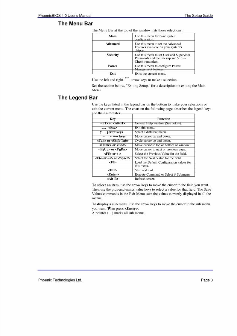
The Menu BarThe Menu Bar at the top of the window lists these selections:
Main Use this menu for basic systemconfiguration.
Advanced Use this menu to set the AdvancedFeatures available on your system'schipset.
Security Use this menu to set User and SupervisorPasswords and the Backup and Virus-Check reminders.
Power Use this menu to configure Power-Management features.
Exit Exits the current menu.
Use the left and right ¥ arrow keys to make a selection.
See the section below, "Exiting Setup," for a description on exiting the Main
Menu.
The Legend BarUse the keys listed in the legend bar on the bottom to make your selections or
exit the current menu. The chart on the following page describes the legend keys
and their alternates:Key Function
<F1> or <Alt-H> General Help window (See below).
<Esc> Exit this menu.
¥ arrow keys Select a different menu.
↑ or ↓ arrow keys Move cursor up and down.
<Tab> or <Shift-Tab> Cycle cursor up and down.
<Home> or <End> Move cursor to top or bottom of window.
<PgUp> or <PgDn> Move cursor to next or previous page.
<F5> or <-> Select the Previous Value for the field.
<F6> or <+> or <Space> Select the Next Value for the field.
<F9> Load the Default Configuration values forthis menu.
<F10> Save and exit.<Enter> Execute Command or Select P Submenu.
<Alt-R> Refresh screen.
To select an item, use the arrow keys to move the cursor to the field you want.
Then use the plus-and-minus value keys to select a value for that field. The Save
Values commands in the Exit Menu save the values currently displayed in all the
menus.
To display a sub menu, use the arrow keys to move the cursor to the sub menu
you want. Then press <Enter>.
A pointer ( ) marks all sub menus.
5/14/2018 PhoenixBIOS4_rev6UserMan - slidepdf.com
http://slidepdf.com/reader/full/phoenixbios4rev6userman 8/88
The Setup Guide PhoenixBIOS 4.0 User's Manual
Page 4 Phoenix Technologies Ltd.
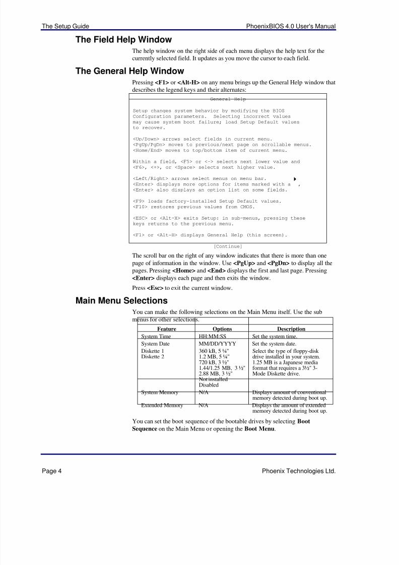
The Field Help WindowThe help window on the right side of each menu displays the help text for the
currently selected field. It updates as you move the cursor to each field.
The General Help WindowPressing <F1> or <Alt-H> on any menu brings up the General Help window that
describes the legend keys and their alternates:
General Help
Setup changes system behavior by modifying the BIOS
Configuration parameters. Selecting incorrect values
may cause system boot failure; load Setup Default values
to recover.
<Up/Down> arrows select fields in current menu.
<PgUp/PgDn> moves to previous/next page on scrollable menus.
<Home/End> moves to top/bottom item of current menu.
Within a field, <F5> or <-> selects next lower value and
<F6>, <+>, or <Space> selects next higher value.
<Left/Right> arrows select menus on menu bar.
<Enter> displays more options for items marked with a ,
<Enter> also displays an option list on some fields.
<F9> loads factory-installed Setup Default values.
<F10> restores previous values from CMOS.
<ESC> or <Alt-X> exits Setup: in sub-menus, pressing these
keys returns to the previous menu.
<F1> or <Alt-H> displays General Help (this screen).
[Continue]
The scroll bar on the right of any window indicates that there is more than one
page of information in the window. Use <PgUp> and <PgDn> to display all the
pages. Pressing <Home> and <End> displays the first and last page. Pressing
<Enter> displays each page and then exits the window.
Press <Esc> to exit the current window.
Main Menu SelectionsYou can make the following selections on the Main Menu itself. Use the sub
menus for other selections.
Feature Options Description
System Time HH:MM:SS Set the system time.
System Date MM/DD/YYYY Set the system date.
Diskette 1Diskette 2
360 kB, 5 ¼"1.2 MB, 5 ¼"720 kB, 3 ½"1.44/1.25 MB, 3 ½"2.88 MB, 3 ½"Not installedDisabled
Select the type of floppy-disk drive installed in your system.1.25 MB is a Japanese mediaformat that requires a 3½" 3-Mode Diskette drive.
System Memory N/A Displays amount of conventionalmemory detected during boot up.
Extended Memory N/A Displays the amount of extendedmemory detected during boot up.
You can set the boot sequence of the bootable drives by selecting Boot
Sequence on the Main Menu or opening the Boot Menu.
5/14/2018 PhoenixBIOS4_rev6UserMan - slidepdf.com
http://slidepdf.com/reader/full/phoenixbios4rev6userman 9/88
PhoenixBIOS 4.0 User's Manual The Setup Guide
Phoenix Technologies Ltd. Page 5
Master and Slave Sub-MenusThe Master and Slave sub-menus accessed from the Main Menu control thesetypes of devices:
• Hard-disk drives
• Removable-disk drives such as Zip drives
• CD-ROM drives
PhoenixBIOS 4.0 supports up to two IDE disk adapters, called primary andsecondary adapters. Each adapter supports one master drive and one optionalslave drive in these possible combinations:
• 1 Master
• 1 Master, 1 Slave
• 2 Masters
• 2 Masters, 1 Slave
• 2 Masters, 2 Slaves
There is one IDE connector for each adapter on your machine, usually labeled"Primary IDE" and "Secondary IDE." There are usually two connectors on eachribbon cable attached to each IDE connector. When you have connected twodrives to these connectors, the one on the end of the cable is the Master.
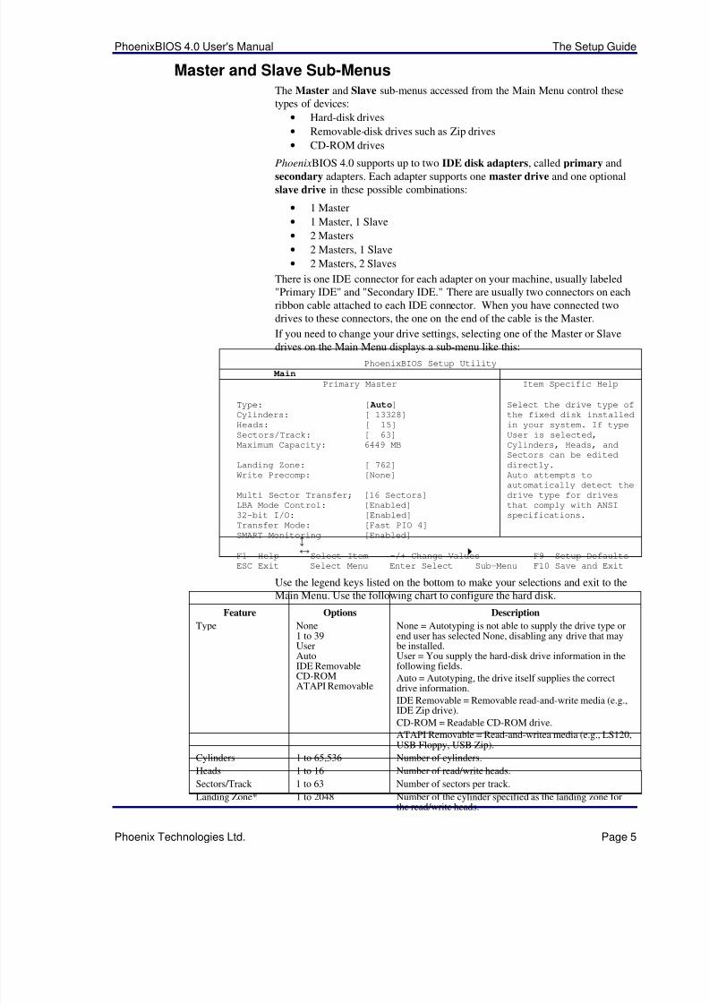
If you need to change your drive settings, selecting one of the Master or Slavedrives on the Main Menu displays a sub-menu like this:
PhoenixBIOS Setup Utility
Main
Primary Master Item Specific Help
Type: [ Auto]Cylinders: [ 13328]
Heads: [ 15]
Sectors/Track: [ 63]
Maximum Capacity: 6449 MB
Landing Zone: [ 762]
Write Precomp: [None]
Multi Sector Transfer; [16 Sectors]
LBA Mode Control: [Enabled]
32-bit I/O: [Enabled]
Transfer Mode: [Fast PIO 4]
SMART Monitoring [Enabled]
Select the drive type of
the fixed disk installed
in your system. If type
User is selected,
Cylinders, Heads, and
Sectors can be edited
directly.
Auto attempts to
automatically detect the
drive type for drives
that comply with ANSI
specifications.
F1 Help¦
Select Item -/+ Change Values F9 Setup Defaults
ESC Exit¥
Select Menu Enter Select Sub-Menu F10 Save and Exit
Use the legend keys listed on the bottom to make your selections and exit to theMain Menu. Use the following chart to configure the hard disk.
Feature Options Description
Type None1 to 39UserAutoIDE Removable
CD-ROMATAPI Removable
None = Autotyping is not able to supply the drive type orend user has selected None, disabling any drive that maybe installed.User = You supply the hard-disk drive information in thefollowing fields.
Auto = Autotyping, the drive itself supplies the correctdrive information.
IDE Removable = Removable read-and-write media (e.g.,IDE Zip drive).
CD-ROM = Readable CD-ROM drive.
ATAPI Removable = Read-and-writea media (e.g., LS120,USB Floppy, USB Zip).
Cylinders 1 to 65,536 Number of cylinders.
Heads 1 to 16 Number of read/write heads.
Sectors/Track 1 to 63 Number of sectors per track.
Landing Zone* 1 to 2048 Number of the cylinder specified as the landing zone forthe read/write heads.
5/14/2018 PhoenixBIOS4_rev6UserMan - slidepdf.com
http://slidepdf.com/reader/full/phoenixbios4rev6userman 10/88
The Setup Guide PhoenixBIOS 4.0 User's Manual
Page 6 Phoenix Technologies Ltd.
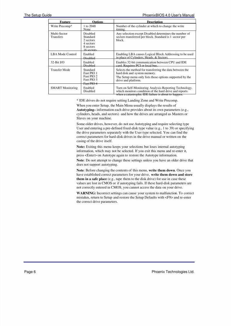
Feature Options Description
Write Precomp* 1 to 2048None
Number of the cylinder at which to change the writetiming.
Multi-SectorTransfers
DisabledStandard2 sectors4 sectors8 sectors16 sectors
Any selection except Disabled determines the number of sectors transferred per block. Standard is 1 sector perblock.
LBA Mode Control EnabledDisabled
Enabling LBA causes Logical Block Addressing to be usedin place of Cylinders, Heads, & Sectors.
32-Bit I/O EnabledDisabled
Enables 32-bit communication between CPU and IDEcard. Requires PCI or local bus.
Transfer Mode StandardFast PIO 1Fast PIO 2Fast PIO 3
Fast PIO 4
Selects the method for transferring the data between thehard disk and system memory.
The Setup menu only lists those options supported by thedrive and platform.
SMART Monitoring EnabledDisabled
Turn on Self-Monitoring Analysis-Reporting Technology,which monitors condition of the hard drive and reportswhen a catastrophic IDE failure is about to happen.
* IDE drives do not require setting Landing Zone and Write Precomp.
When you enter Setup, the Main Menu usually displays the results of
Autotyping– information each drive provides about its own parameters (e.g.,cylinders, heads, and sectors)–and how the drives are arranged as Masters orSlaves on your machine.
Some older drives, however, do not use Autotyping and require selecting typeUser and entering a pre-defined fixed-disk type value (e.g., 1 to 39) or specifyingthe drive parameters separately with the User type selected. You can find thecorrect parameters for hard-disk drives in the drive manual or written on thecasing of the drive itself.
Note: Exiting this menu keeps your selections but loses internal autotypinginformation, which may not be selected. If you exit this menu and re-enter it,press <Enter> on Autotype again to restore the Autotype information.
Note: Do not attempt to change these settings unless you have an older drive that
does not support autotyping.Note: Before changing the contents of this menu, write them down. Once youhave established correct parameters for your drive, write them down and store
them in a safe place (e.g., tape them to the disk drive) for use in case thesevalues are lost in CMOS or if autotyping fails. If these hard-disk parameters arenot correctly entered in CMOS, you cannot access the data on your drive.
WARNING: Incorrect settings can cause your system to malfunction. To correctmistakes, return to Setup and restore the Setup Defaults with <F9> and re-enterthe correct drive parameters.

5/14/2018 PhoenixBIOS4_rev6UserMan - slidepdf.com
http://slidepdf.com/reader/full/phoenixbios4rev6userman 11/88
PhoenixBIOS 4.0 User's Manual The Setup Guide
Phoenix Technologies Ltd. Page 7
Memory CacheEnabling cache saves time for the CPU by holding data most recently accessedin regular memory (dynamic RAM or DRAM) in a special storage area of staticRAM (SRAM), which is faster. Before accessing regular memory, the CPU firstaccesses the cache. If it does not find the data it is looking for there, it accessesregular memory. Selecting "Memory Cache" from the Main menu displays amenu like the one shown here. The actual features displayed depend on your
system's hardware.PhoenixBIOS Setup Utility
Main
Memory Cache Item Specific Help
External cache: [Enabled]
Cache Interleave: [Disabled]
Cache Write Back: [Disabled]
Cache Read Cycles: [2T]
Cache System BIOS: [Disabled]
Cache Video BIOS: [Enabled]
Cache E800 - EFFF: [Disabled]
Cache E000 - E7FF: [Disabled]
Cache D800 - DFFF: [Disabled]
Cache D000 - D7FF: [Disabled]Cache C800 - CFFF: [Disabled]
Cache C800 - CFFF: [Disabled]
Non-cacheable Regions
Region 0, start: [ 0 kB]
Region 0, size: [Disabled]
Region 1, start: [ 0 kB]
Region 1, size: [Disabled]
Sets the state of the
external system memory
cache.
F1 Help¦
Select Item -/+ Change Values F9 Setup Defaults
ESC Exit ¥ Select Menu Enter Select Sub-Menu F10 Save and Exit
Use the legend keys listed on the bottom to make your selections and exit to theMain Menu. Use this chart to configure the memory cache.
Feature Options Description
External Cache EnabledDisabled.
Generally enables or disables all memory caching.
Cache Interleave EnabledDisabled
Interleaves multiple banks of static RAM. Improves CPU access.
Cache Write Back EnabledDisabled
Enables caches to both read and write to memory. Disabled caches readsonly.
Cache Read Cycles ChipsetDependent
Sets the number of clock pulses for reading from the cache. Shorter numberof pulses improves performance.
Cache Write Cycles ChipsetDependent
Sets the number of clock pulses for writing to the cache. Shorter number of pulses improves performance.
Cache System BIOS EnabledDisabled
Caches the system BIOS and improves performance.
Cache Video BIOS EnabledDisabled
Caches the video BIOS and improves performance.
Cache segments, e.g., E800-EFFF Enabled
Disabled
Controls caching of individual segments of memory usually reserved for
shadowing system or option ROMsNon-cacheable regions: Specifies areas of regular and extended memory as non-cacheable regions.
Region 0, start 0Multiples of 64
Multiples of 64 define start of non-cacheable region 0 in kilobytes.
Region 0, size DisabledMultiples of 64
Disabling makes this region available for cache. Multiples of 64 define sizeof non-cacheable region 0 in kilobytes.
Region 1, start 0Multiples of 64
Multiples of 64 define start of non-cacheable region 1 in kilobytes.
Region 1, size DisabledMultiples of 64
Disabling makes this region available for cache. Multiples of 64 define sizeof non-cacheable region 1 in kilobytes.
WARNING: Incorrect settings can cause your system to malfunction. To correctmistakes, return to Setup and restore the Setup Defaults with <F9>.
5/14/2018 PhoenixBIOS4_rev6UserMan - slidepdf.com
http://slidepdf.com/reader/full/phoenixbios4rev6userman 12/88
The Setup Guide PhoenixBIOS 4.0 User's Manual
Page 8 Phoenix Technologies Ltd.
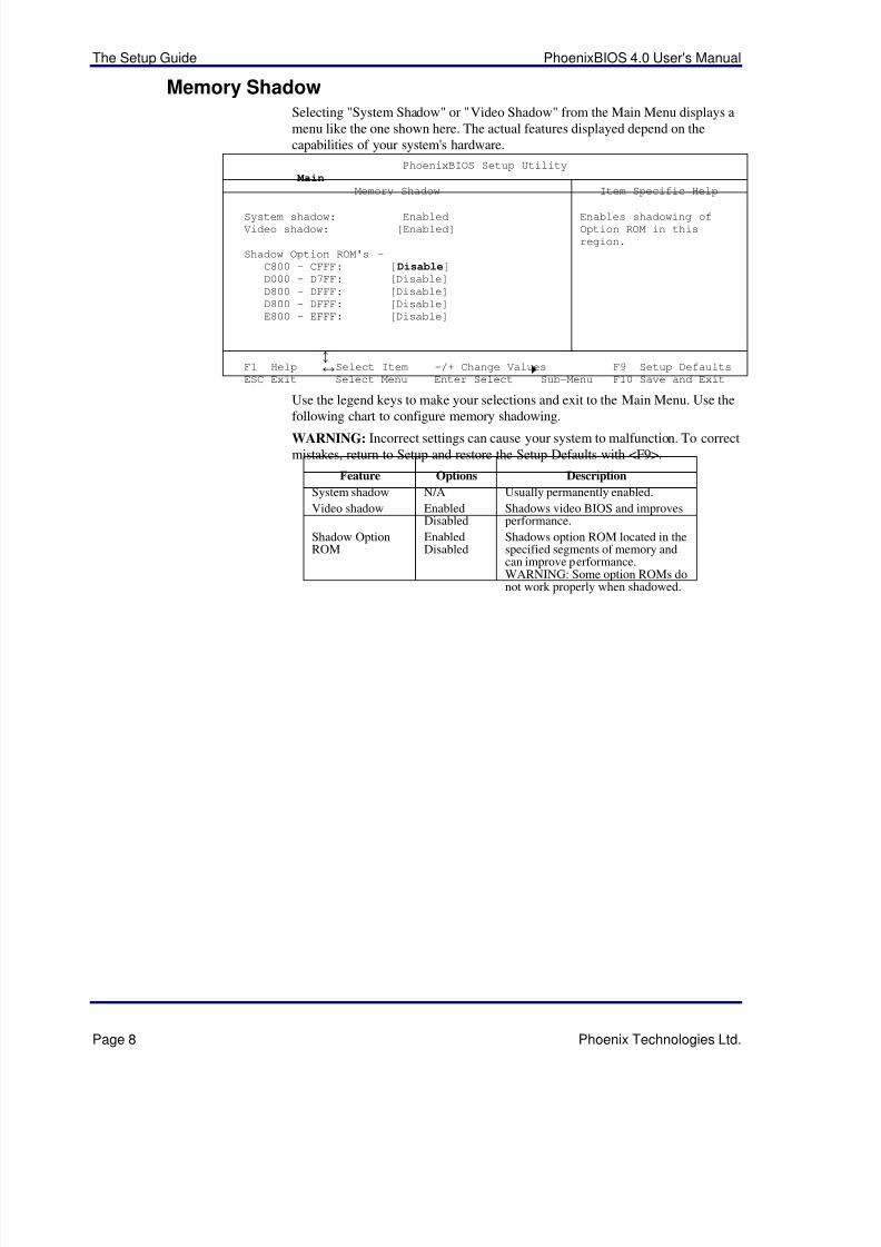
Memory ShadowSelecting "System Shadow" or "Video Shadow" from the Main Menu displays amenu like the one shown here. The actual features displayed depend on thecapabilities of your system's hardware.
PhoenixBIOS Setup Utility
Main
Memory Shadow Item Specific Help
System shadow: Enabled
Video shadow: [Enabled]
Shadow Option ROM's –
C800 - CFFF: [Disable]D000 - D7FF: [Disable]
D800 - DFFF: [Disable]
D800 - DFFF: [Disable]
E800 - EFFF: [Disable]
Enables shadowing of
Option ROM in this
region.
F1 Help¦
Select Item -/+ Change Values F9 Setup Defaults
ESC Exit¥
Select Menu Enter Select Sub-Menu F10 Save and Exit
Use the legend keys to make your selections and exit to the Main Menu. Use the
following chart to configure memory shadowing.WARNING: Incorrect settings can cause your system to malfunction. To correctmistakes, return to Setup and restore the Setup Defaults with <F9>.
Feature Options Description
System shadow N/A Usually permanently enabled.
Video shadow EnabledDisabled
Shadows video BIOS and improvesperformance.
Shadow OptionROM
EnabledDisabled
Shadows option ROM located in thespecified segments of memory andcan improve performance.WARNING: Some option ROMs donot work properly when shadowed.
5/14/2018 PhoenixBIOS4_rev6UserMan - slidepdf.com
http://slidepdf.com/reader/full/phoenixbios4rev6userman 13/88
PhoenixBIOS 4.0 User's Manual The Setup Guide
Phoenix Technologies Ltd. Page 9
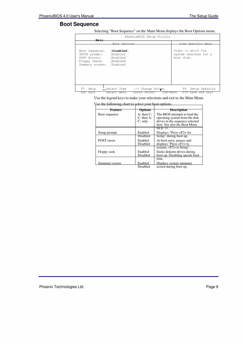
Boot SequenceSelecting "Boot Sequence" on the Main Menu displays the Boot Options menu.
PhoenixBIOS Setup Utility
Main
Boot Options Item Specific Help
Boot sequence: [Disabled]SETUP prompt: [Enabled]
POST Errors: [Enabled]Floppy check: [Enabled]
Summary screen: [Enabled]
Order in which the
system searches for a
boot disk.
F1 Help¦
Select Item -/+ Change Values F9 Setup Defaults
ESC Exit ¥ Select Menu Enter Select Sub-Menu F10 Save and Exit
Use the legend keys to make your selections and exit to the Main Menu.
Use the following chart to select your boot options.
Feature Options Description
Boot sequence A: then C;C: then A:C: only
The BIOS attempts to load theoperating system from the disk drives in the sequence selectedhere. See also the Boot Menuon p. 11.
Setup prompt EnabledDisabled
Displays "Press <F2> forSetup" during boot up.
POST errors EnabledDisabled
At boot error, pauses anddisplays "Press <F1> toresume, <F2> to Setup".
Floppy seek EnabledDisabled
Seeks diskette drives duringboot up. Disabling speeds boottime.
Summary screen EnabledDisabled
Displays system summaryscreen during boot up.

5/14/2018 PhoenixBIOS4_rev6UserMan - slidepdf.com
http://slidepdf.com/reader/full/phoenixbios4rev6userman 14/88
The Setup Guide PhoenixBIOS 4.0 User's Manual
Page 10 Phoenix Technologies Ltd.
Keyboard FeaturesSelecting "Numlock" on the Main Menu displays the Keyboard Features menu:
PhoenixBIOS Setup Utility
Main
Keyboard Features Item Specific Help
Numlock: [Off]Key Click: [Disabled]
Keyboard auto-repeat rate: [30/sec]Keyboard auto-repeat delay: [1/2 sec]
Selects power-on state
for Numlock key.
F1 Help¦
Select Item -/+ Change Values F9 Setup Defaults
ESC Exit ¥ Select Menu Enter Select Sub-Menu F10 Save and Exit
Use the legend keys to make your selections and exit to the Main Menu.
Use the following chart to configure the keyboard features:
Feature Options Description
Numlock AutoOnOff
On or Off turns NumLock on oroff at boot up. Auto turnsNumLock on if it finds anumeric key pad.
Key Click EnabledDisabled
Turns audible key click on.
Keyboard auto-repeat rate 2/sec6/sec10/sec13.3/sec21.8/sec26.7/sec30/sec
Sets the number of times asecond to repeat a keystrokewhen you hold the key down.
Keyboard auto-lag delay ¼ sec½ sec¾ sec1 sec
Sets the delay time after the keyis held down before it begins torepeat the keystroke.
5/14/2018 PhoenixBIOS4_rev6UserMan - slidepdf.com
http://slidepdf.com/reader/full/phoenixbios4rev6userman 15/88
PhoenixBIOS 4.0 User's Manual The Setup Guide
Phoenix Technologies Ltd. Page 11
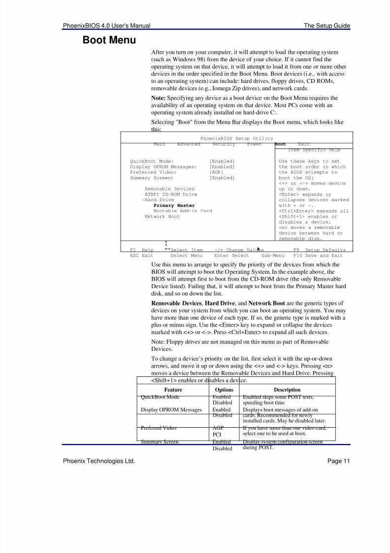
Boot MenuAfter you turn on your computer, it will attempt to load the operating system(such as Windows 98) from the device of your choice. If it cannot find theoperating system on that device, it will attempt to load it from one or more otherdevices in the order specified in the Boot Menu. Boot devices (i.e., with accessto an operating system) can include: hard drives, floppy drives, CD ROMs,removable devices (e.g., Iomega Zip drives), and network cards.
Note: Specifying any device as a boot device on the Boot Menu requires theavailability of an operating system on that device. Most PCs come with anoperating system already installed on hard-drive C:.
Selecting "Boot" from the Menu Bar displays the Boot menu, which looks likethis:
PhoenixBIOS Setup Utility
Main Advanced Security Power Boot Exit
Item Specific Help
QuickBoot Mode: [Enabled]
Display OPROM Messages: [Enabled]
Preferred Video: [AGP]
Summary Screen: [Enabled]
Removable Devices
ATAPI CD-ROM Drive
-Hard Drive
Primary MasterBootable Add-in Card
Network Boot
Use these keys to set
the boot order in which
the BIOS attempts to
boot the OS:
<+> or <-> moves device
up or down.
<Enter> expands or
collapses devices marked
with + or -.
<Ctrl+Enter> expands all
<Shift+1> enables or
disables a device.
<n> moves a removable
device between hard or
removable disk.
F1 Help¦
Select Item -/+ Change Values F9 Setup Defaults
ESC Exit ¥ Select Menu Enter Select Sub-Menu F10 Save and Exit
Use this menu to arrange to specify the priority of the devices from which theBIOS will attempt to boot the Operating System. In the example above, the
BIOS will attempt first to boot from the CD-ROM drive (the only RemovableDevice listed). Failing that, it will attempt to boot from the Primary Master harddisk, and so on down the list.
Removable Devices, Hard Drive, and Network Boot are the generic types of devices on your system from which you can boot an operating system. You mayhave more than one device of each type. If so, the generic type is marked with aplus or minus sign. Use the <Enter> key to expand or collapse the devicesmarked with <+> or <->. Press <Ctrl+Enter> to expand all such devices.
Note: Floppy drives are not managed on this menu as part of RemovableDevices.
To change a device’s priority on the list, first select it with the up-or-downarrows, and move it up or down using the <+> and <-> keys. Pressing <n>
moves a device between the Removable Devices and Hard Drive. Pressing<Shift+1> enables or disables a device.
Feature Options Description
QuickBoot Mode EnabledDisabled
Enabled skips some POST tests,speeding boot time
Display OPROM Messages EnabledDisabled
Displays boot messages of add-oncards. Recommended for newlyinstalled cards. May be disabled later.
Preferred Video AGP
PCI
If you have more than one video card,select one to be used at boot.
Summary Screen Enabled
Disabled
Display system configuration screenduring POST.
5/14/2018 PhoenixBIOS4_rev6UserMan - slidepdf.com
http://slidepdf.com/reader/full/phoenixbios4rev6userman 16/88
The Setup Guide PhoenixBIOS 4.0 User's Manual
Page 12 Phoenix Technologies Ltd.
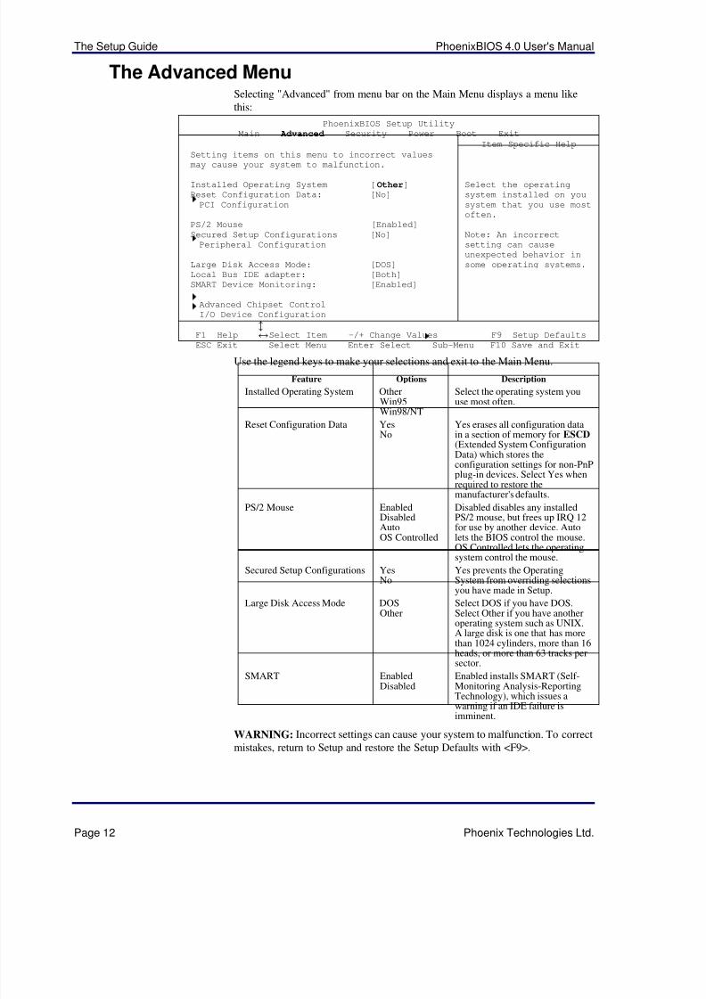
The Advanced MenuSelecting "Advanced" from menu bar on the Main Menu displays a menu likethis:
PhoenixBIOS Setup Utility
Main Advanced Security Power Boot Exit
Item Specific Help
Setting items on this menu to incorrect values
may cause your system to malfunction.
Installed Operating System [Other]Reset Configuration Data: [No]
PCI Configuration
PS/2 Mouse [Enabled]
Secured Setup Configurations [No]
Peripheral Configuration
Large Disk Access Mode: [DOS]
Local Bus IDE adapter: [Both]
SMART Device Monitoring: [Enabled]
Advanced Chipset Control
I/O Device Configuration
Select the operating
system installed on you
system that you use most
often.
Note: An incorrect
setting can cause
unexpected behavior in
some operating systems.
F1 Help¦
Select Item -/+ Change Values F9 Setup DefaultsESC Exit ¥ Select Menu Enter Select Sub-Menu F10 Save and Exit
Use the legend keys to make your selections and exit to the Main Menu.
Feature Options Description
Installed Operating System OtherWin95Win98/NT
Select the operating system youuse most often.
Reset Configuration Data YesNo
Yes erases all configuration datain a section of memory for ESCD (Extended System ConfigurationData) which stores theconfiguration settings for non-PnPplug-in devices. Select Yes whenrequired to restore themanufacturer's defaults.
PS/2 Mouse EnabledDisabledAutoOS Controlled
Disabled disables any installedPS/2 mouse, but frees up IRQ 12for use by another device. Autolets the BIOS control the mouse.OS Controlled lets the operatingsystem control the mouse.
Secured Setup Configurations YesNo
Yes prevents the OperatingSystem from overriding selectionsyou have made in Setup.
Large Disk Access Mode DOSOther
Select DOS if you have DOS.Select Other if you have anotheroperating system such as UNIX.A large disk is one that has morethan 1024 cylinders, more than 16heads, or more than 63 tracks persector.
SMART EnabledDisabled
Enabled installs SMART (Self-Monitoring Analysis-ReportingTechnology), which issues awarning if an IDE failure isimminent.
WARNING: Incorrect settings can cause your system to malfunction. To correctmistakes, return to Setup and restore the Setup Defaults with <F9>.
5/14/2018 PhoenixBIOS4_rev6UserMan - slidepdf.com
http://slidepdf.com/reader/full/phoenixbios4rev6userman 17/88
PhoenixBIOS 4.0 User's Manual The Setup Guide
Phoenix Technologies Ltd. Page 13
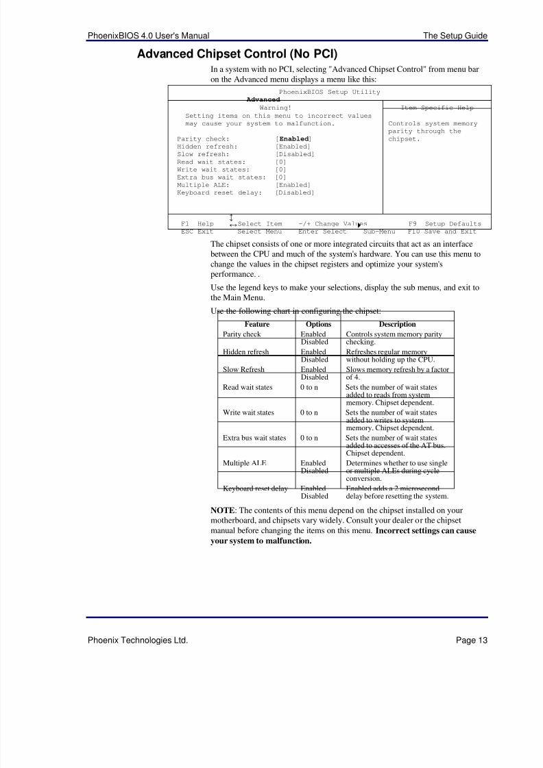
Advanced Chipset Control (No PCI)In a system with no PCI, selecting "Advanced Chipset Control" from menu baron the Advanced menu displays a menu like this:
PhoenixBIOS Setup Utility
Advanced
Warning! Item Specific Help
Setting items on this menu to incorrect values
may cause your system to malfunction.
Parity check: [Enabled]Hidden refresh: [Enabled]
Slow refresh: [Disabled]
Read wait states: [0]
Write wait states: [0]
Extra bus wait states: [0]
Multiple ALE: [Enabled]
Keyboard reset delay: [Disabled]
Controls system memory
parity through thechipset.
F1 Help ¦ Select Item -/+ Change Values F9 Setup Defaults
ESC Exit¥
Select Menu Enter Select
Sub-Menu F10 Save and Exit
The chipset consists of one or more integrated circuits that act as an interfacebetween the CPU and much of the system's hardware. You can use this menu tochange the values in the chipset registers and optimize your system'sperformance. .
Use the legend keys to make your selections, display the sub menus, and exit tothe Main Menu.
Use the following chart in configuring the chipset:
Feature Options Description
Parity check EnabledDisabled
Controls system memory paritychecking.
Hidden refresh EnabledDisabled
Refreshes regular memorywithout holding up the CPU.
Slow Refresh EnabledDisabled
Slows memory refresh by a factorof 4.
Read wait states 0 to n Sets the number of wait statesadded to reads from systemmemory. Chipset dependent.
Write wait states 0 to n Sets the number of wait statesadded to writes to systemmemory. Chipset dependent.
Extra bus wait states 0 to n Sets the number of wait statesadded to accesses of the AT bus.Chipset dependent.
Multiple ALE EnabledDisabled
Determines whether to use singleor multiple ALEs during cycleconversion.
Keyboard reset delay EnabledDisabled
Enabled adds a 2 microseconddelay before resetting the system.
NOTE: The contents of this menu depend on the chipset installed on your
motherboard, and chipsets vary widely. Consult your dealer or the chipsetmanual before changing the items on this menu. Incorrect settings can cause
your system to malfunction.
5/14/2018 PhoenixBIOS4_rev6UserMan - slidepdf.com
http://slidepdf.com/reader/full/phoenixbios4rev6userman 18/88
The Setup Guide PhoenixBIOS 4.0 User's Manual
Page 14 Phoenix Technologies Ltd.
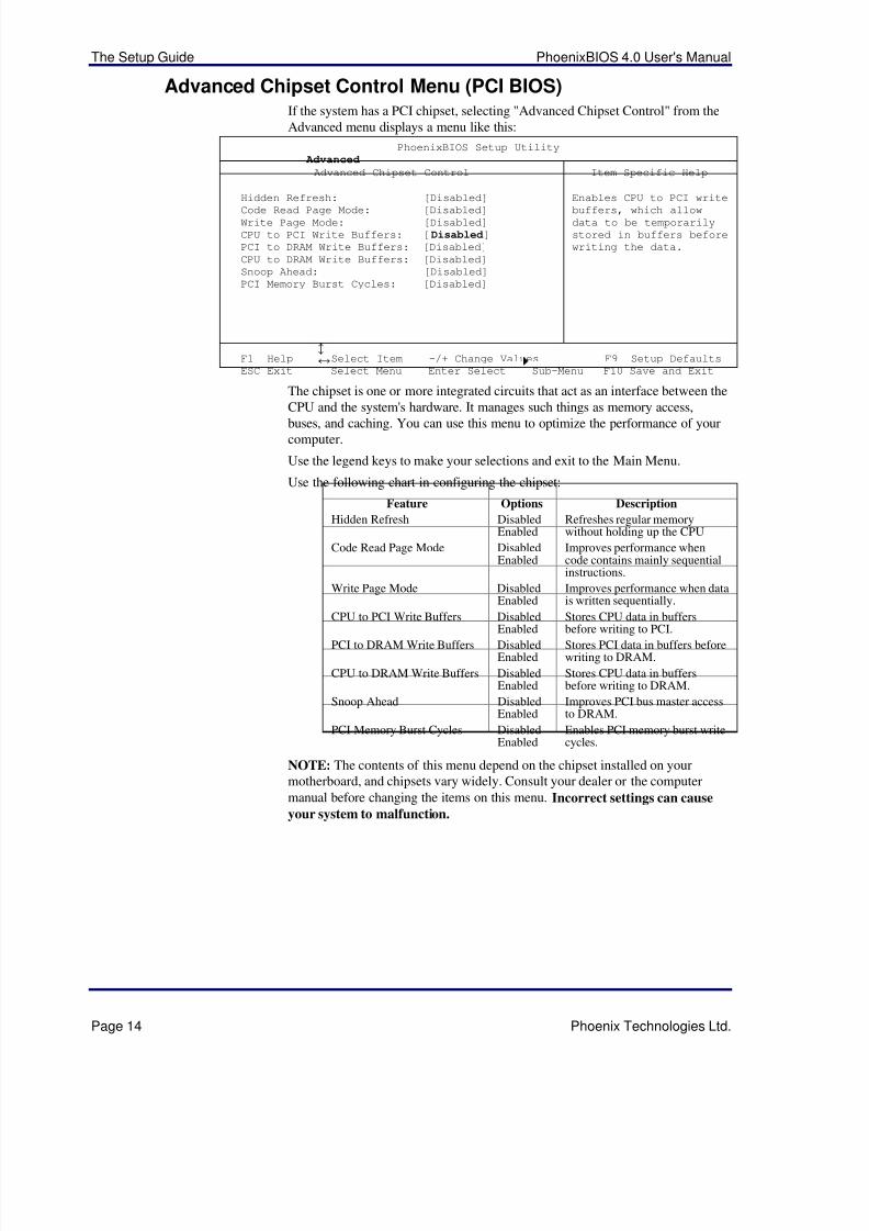
Advanced Chipset Control Menu (PCI BIOS)If the system has a PCI chipset, selecting "Advanced Chipset Control" from theAdvanced menu displays a menu like this:
PhoenixBIOS Setup Utility
Advanced
Advanced Chipset Control Item Specific Help
Hidden Refresh: [Disabled]
Code Read Page Mode: [Disabled]Write Page Mode: [Disabled]
CPU to PCI Write Buffers: [Disabled]PCI to DRAM Write Buffers: [Disabled]
CPU to DRAM Write Buffers: [Disabled]
Snoop Ahead: [Disabled]
PCI Memory Burst Cycles: [Disabled]
Enables CPU to PCI write
buffers, which allowdata to be temporarily
stored in buffers before
writing the data.
F1 Help ¦ Select Item -/+ Change Values F9 Setup Defaults
ESC Exit¥
Select Menu Enter Select
Sub-Menu F10 Save and Exit
The chipset is one or more integrated circuits that act as an interface between theCPU and the system's hardware. It manages such things as memory access,buses, and caching. You can use this menu to optimize the performance of yourcomputer.
Use the legend keys to make your selections and exit to the Main Menu.
Use the following chart in configuring the chipset:
Feature Options Description
Hidden Refresh DisabledEnabled
Refreshes regular memorywithout holding up the CPU
Code Read Page Mode DisabledEnabled
Improves performance whencode contains mainly sequentialinstructions.
Write Page Mode DisabledEnabled
Improves performance when datais written sequentially.
CPU to PCI Write Buffers DisabledEnabled
Stores CPU data in buffersbefore writing to PCI.
PCI to DRAM Write Buffers DisabledEnabled
Stores PCI data in buffers beforewriting to DRAM.
CPU to DRAM Write Buffers DisabledEnabled
Stores CPU data in buffersbefore writing to DRAM.
Snoop Ahead DisabledEnabled
Improves PCI bus master accessto DRAM.
PCI Memory Burst Cycles DisabledEnabled
Enables PCI memory burst writecycles.
NOTE: The contents of this menu depend on the chipset installed on yourmotherboard, and chipsets vary widely. Consult your dealer or the computer
manual before changing the items on this menu. Incorrect settings can cause
your system to malfunction.
5/14/2018 PhoenixBIOS4_rev6UserMan - slidepdf.com
http://slidepdf.com/reader/full/phoenixbios4rev6userman 19/88
PhoenixBIOS 4.0 User's Manual The Setup Guide
Phoenix Technologies Ltd. Page 15
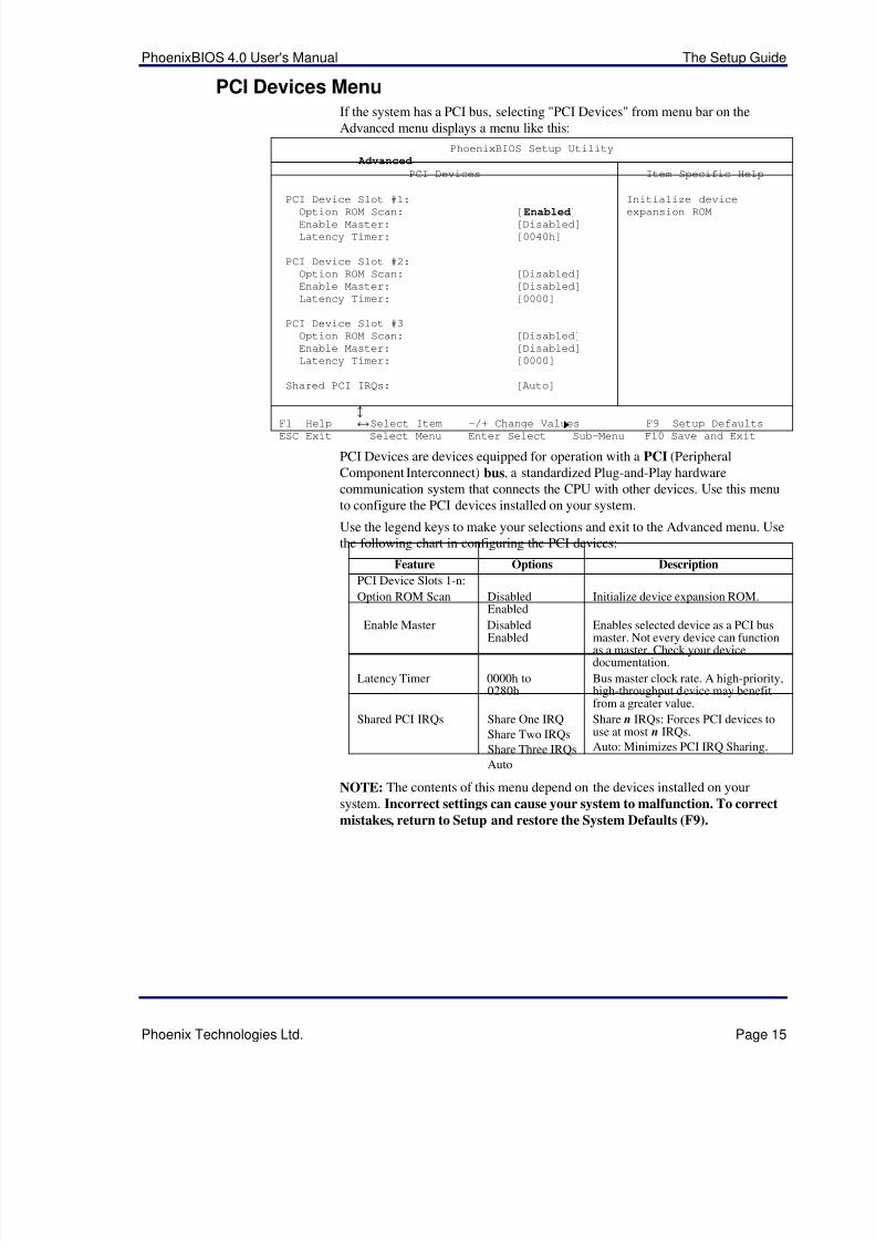
PCI Devices MenuIf the system has a PCI bus, selecting "PCI Devices" from menu bar on theAdvanced menu displays a menu like this:
PhoenixBIOS Setup Utility
Advanced
PCI Devices Item Specific Help
PCI Device Slot #1:
Option ROM Scan: [Enabled]Enable Master: [Disabled]
Latency Timer: [0040h]
PCI Device Slot #2:
Option ROM Scan: [Disabled]
Enable Master: [Disabled]
Latency Timer: [0000]
PCI Device Slot #3
Option ROM Scan: [Disabled]
Enable Master: [Disabled]
Latency Timer: [0000]
Shared PCI IRQs: [Auto]
Initialize device
expansion ROM
F1 Help ¦ Select Item -/+ Change Values F9 Setup Defaults
ESC Exit ¥ Select Menu Enter Select Sub-Menu F10 Save and Exit
PCI Devices are devices equipped for operation with a PCI (PeripheralComponent Interconnect) bus, a standardized Plug-and-Play hardwarecommunication system that connects the CPU with other devices. Use this menuto configure the PCI devices installed on your system.
Use the legend keys to make your selections and exit to the Advanced menu. Usethe following chart in configuring the PCI devices:
Feature Options Description
PCI Device Slots 1-n:
Option ROM Scan DisabledEnabled
Initialize device expansion ROM.
Enable Master DisabledEnabled Enables selected device as a PCI busmaster. Not every device can functionas a master. Check your devicedocumentation.
Latency Timer 0000h to0280h
Bus master clock rate. A high-priority,high-throughput device may benefitfrom a greater value.
Shared PCI IRQs Share One IRQ
Share Two IRQs
Share Three IRQs
Auto
Share n IRQs: Forces PCI devices touse at most n IRQs.
Auto: Minimizes PCI IRQ Sharing.
NOTE: The contents of this menu depend on the devices installed on your
system. Incorrect settings can cause your system to malfunction. To correct
mistakes, return to Setup and restore the System Defaults (F9).
5/14/2018 PhoenixBIOS4_rev6UserMan - slidepdf.com
http://slidepdf.com/reader/full/phoenixbios4rev6userman 20/88
The Setup Guide PhoenixBIOS 4.0 User's Manual
Page 16 Phoenix Technologies Ltd.
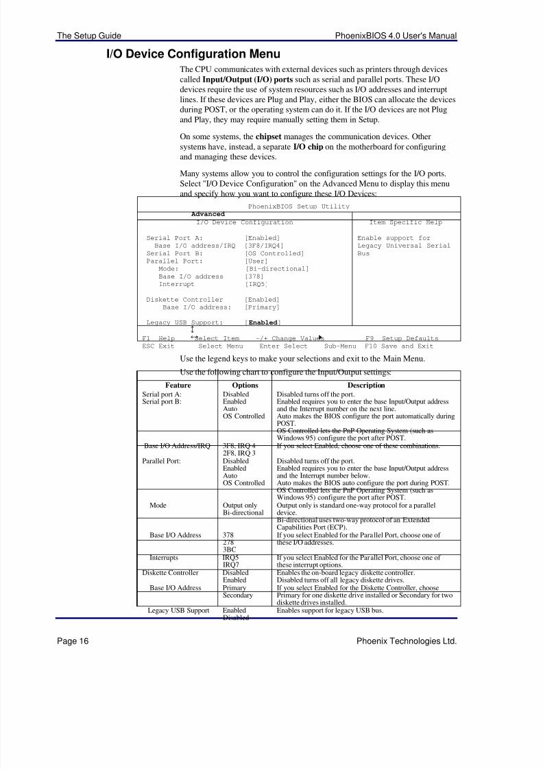
I/O Device Configuration MenuThe CPU communicates with external devices such as printers through devicescalled Input/Output (I/O) ports such as serial and parallel ports. These I/Odevices require the use of system resources such as I/O addresses and interruptlines. If these devices are Plug and Play, either the BIOS can allocate the devicesduring POST, or the operating system can do it. If the I/O devices are not Plugand Play, they may require manually setting them in Setup.
On some systems, the chipset manages the communication devices. Othersystems have, instead, a separate I/O chip on the motherboard for configuringand managing these devices.
Many systems allow you to control the configuration settings for the I/O ports.Select "I/O Device Configuration" on the Advanced Menu to display this menuand specify how you want to configure these I/O Devices:
PhoenixBIOS Setup Utility
Advanced
I/O Device Configuration Item Specific Help
Serial Port A: [Enabled]
Base I/O address/IRQ [3F8/IRQ4]
Serial Port B: [OS Controlled]
Parallel Port: [User]Mode: [Bi-directional]
Base I/O address [378]
Interrupt [IRQ5]
Diskette Controller [Enabled]
Base I/O address: [Primary]
Legacy USB Support: [Enabled]
Enable support for
Legacy Universal Serial
Bus
F1 Help ¦ Select Item -/+ Change Values F9 Setup Defaults
ESC Exit¥
Select Menu Enter Select
Sub-Menu F10 Save and Exit
Use the legend keys to make your selections and exit to the Main Menu.
Use the following chart to configure the Input/Output settings:
Feature Options Description
Serial port A:Serial port B:
DisabledEnabledAutoOS Controlled
Disabled turns off the port.Enabled requires you to enter the base Input/Output addressand the Interrupt number on the next line.Auto makes the BIOS configure the port automatically duringPOST.OS Controlled lets the PnP Operating System (such asWindows 95) configure the port after POST.
Base I/O Address/IRQ 3F8, IRQ 42F8, IRQ 3
If you select Enabled, choose one of these combinations.
Parallel Port: DisabledEnabledAutoOS Controlled
Disabled turns off the port.Enabled requires you to enter the base Input/Output addressand the Interrupt number below.Auto makes the BIOS auto configure the port during POST.OS Controlled lets the PnP Operating System (such asWindows 95) configure the port after POST.
Mode Output onlyBi-directional
Output only is standard one-way protocol for a paralleldevice.
Bi-directional uses two-way protocol of an ExtendedCapabilities Port (ECP).
Base I/O Address 3782783BC
If you select Enabled for the Parallel Port, choose one of these I/O addresses.
Interrupts IRQ5IRQ7
If you select Enabled for the Parallel Port, choose one of these interrupt options.
Diskette Controller DisabledEnabled
Enables the on-board legacy diskette controller.Disabled turns off all legacy diskette drives.
Base I/O Address PrimarySecondary
If you select Enabled for the Diskette Controller, choosePrimary for one diskette drive installed or Secondary for twodiskette drives installed.
Legacy USB Support EnabledDisabled
Enables support for legacy USB bus.
5/14/2018 PhoenixBIOS4_rev6UserMan - slidepdf.com
http://slidepdf.com/reader/full/phoenixbios4rev6userman 21/88
PhoenixBIOS 4.0 User's Manual The Setup Guide
Phoenix Technologies Ltd. Page 17
Use this menu to specify how the I/O (Input and Output) ports are configured:
• Manually by you.
• Automatically by the BIOS during POST (See "ROM BIOS Functions"on page 32)
• Automatically by a PnP Operating System such as Windows 95 after theOperating System boots.
Warning: If you choose the same I/O address or Interrupt for more than one port, themenu displays an asterisk (*) at the conflicting settings. It also displays this message atthe bottom of the menu:
* Indicates a DMA, Interrupt, I/O, or memory resource
conflict with another device.
Resolve the conflict by selecting another settings for the devices.
5/14/2018 PhoenixBIOS4_rev6UserMan - slidepdf.com
http://slidepdf.com/reader/full/phoenixbios4rev6userman 22/88
The Setup Guide PhoenixBIOS 4.0 User's Manual
Page 18 Phoenix Technologies Ltd.
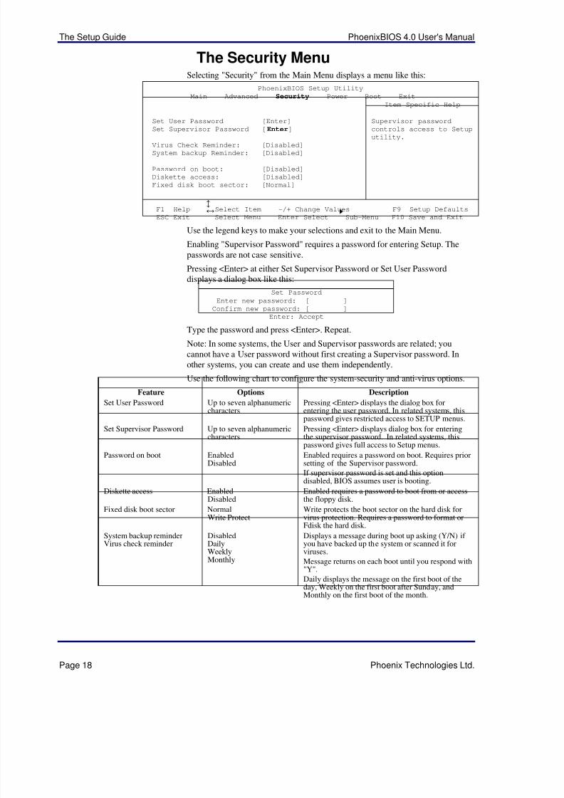
The Security MenuSelecting "Security" from the Main Menu displays a menu like this:
PhoenixBIOS Setup Utility
Main Advanced Security Power Boot Exit
Item Specific Help
Set User Password [Enter]
Set Supervisor Password [Enter]
Virus Check Reminder: [Disabled]
System backup Reminder: [Disabled]
Password on boot: [Disabled]
Diskette access: [Disabled]
Fixed disk boot sector: [Normal]
Supervisor password
controls access to Setup
utility.
F1 Help ¦ Select Item -/+ Change Values F9 Setup Defaults
ESC Exit¥
Select Menu Enter Select
Sub-Menu F10 Save and Exit
Use the legend keys to make your selections and exit to the Main Menu.
Enabling "Supervisor Password" requires a password for entering Setup. Thepasswords are not case sensitive.
Pressing <Enter> at either Set Supervisor Password or Set User Passworddisplays a dialog box like this:
Set Password
Enter new password: [ ]
Confirm new password: [ ]
Enter: Accept
Type the password and press <Enter>. Repeat.
Note: In some systems, the User and Supervisor passwords are related; youcannot have a User password without first creating a Supervisor password. Inother systems, you can create and use them independently.
Use the following chart to configure the system-security and anti-virus options.
Feature Options Description
Set User Password Up to seven alphanumericcharacters Pressing <Enter> displays the dialog box forentering the user password. In related systems, thispassword gives restricted access to SETUP menus.
Set Supervisor Password Up to seven alphanumericcharacters
Pressing <Enter> displays dialog box for enteringthe supervisor password. In related systems, thispassword gives full access to Setup menus.
Password on boot EnabledDisabled
Enabled requires a password on boot. Requires priorsetting of the Supervisor password.
If supervisor password is set and this optiondisabled, BIOS assumes user is booting.
Diskette access EnabledDisabled
Enabled requires a password to boot from or accessthe floppy disk.
Fixed disk boot sector NormalWrite Protect
Write protects the boot sector on the hard disk forvirus protection. Requires a password to format orFdisk the hard disk.
System backup reminderVirus check reminder
DisabledDailyWeeklyMonthly
Displays a message during boot up asking (Y/N) if you have backed up the system or scanned it forviruses.
Message returns on each boot until you respond with"Y".
Daily displays the message on the first boot of theday, Weekly on the first boot after Sunday, andMonthly on the first boot of the month.
5/14/2018 PhoenixBIOS4_rev6UserMan - slidepdf.com
http://slidepdf.com/reader/full/phoenixbios4rev6userman 23/88
PhoenixBIOS 4.0 User's Manual The Setup Guide
Phoenix Technologies Ltd. Page 19
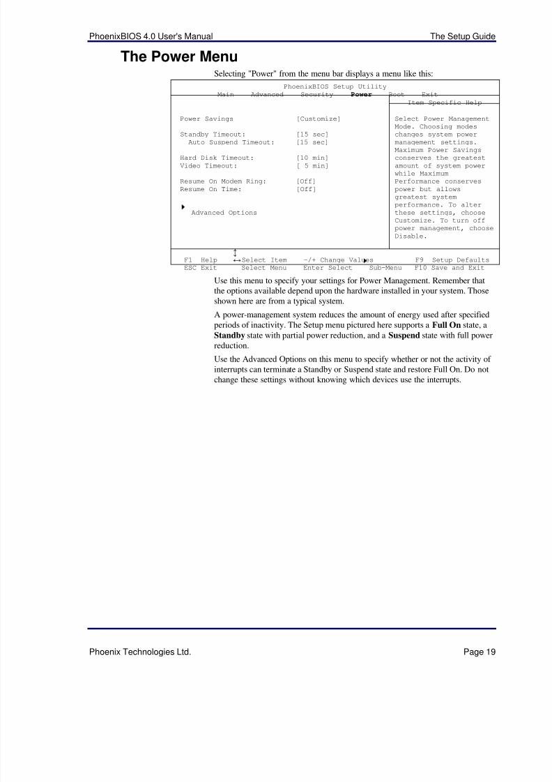
The Power MenuSelecting "Power" from the menu bar displays a menu like this:
PhoenixBIOS Setup Utility
Main Advanced Security Power Boot Exit
Item Specific Help
Power Savings [Customize]
Standby Timeout: [15 sec]Auto Suspend Timeout: [15 sec]
Hard Disk Timeout: [10 min]
Video Timeout: [ 5 min]
Resume On Modem Ring: [Off]
Resume On Time: [Off]
Advanced Options
Select Power Management
Mode. Choosing modes
changes system powermanagement settings.
Maximum Power Savings
conserves the greatest
amount of system power
while Maximum
Performance conserves
power but allows
greatest system
performance. To alter
these settings, choose
Customize. To turn off
power management, choose
Disable.
F1 Help¦
Select Item -/+ Change Values F9 Setup Defaults
ESC Exit¥
Select Menu Enter Select
Sub-Menu F10 Save and Exit
Use this menu to specify your settings for Power Management. Remember thatthe options available depend upon the hardware installed in your system. Thoseshown here are from a typical system.
A power-management system reduces the amount of energy used after specifiedperiods of inactivity. The Setup menu pictured here supports a Full On state, a
Standby state with partial power reduction, and a Suspend state with full powerreduction.
Use the Advanced Options on this menu to specify whether or not the activity of interrupts can terminate a Standby or Suspend state and restore Full On. Do notchange these settings without knowing which devices use the interrupts.
5/14/2018 PhoenixBIOS4_rev6UserMan - slidepdf.com
http://slidepdf.com/reader/full/phoenixbios4rev6userman 24/88
The Setup Guide PhoenixBIOS 4.0 User's Manual
Page 20 Phoenix Technologies Ltd.
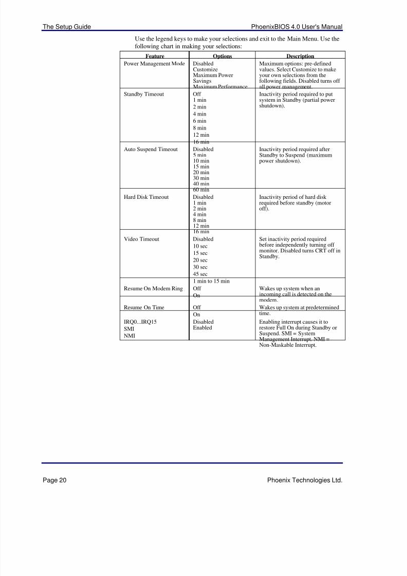
Use the legend keys to make your selections and exit to the Main Menu. Use thefollowing chart in making your selections:
Feature Options Description
Power Management Mode DisabledCustomizeMaximum PowerSavingsMaximum Performance
Maximum options: pre-definedvalues. Select Customize to makeyour own selections from thefollowing fields. Disabled turns off all power management.
Standby Timeout Off 1 min
2 min
4 min
6 min
8 min
12 min
16 min
Inactivity period required to putsystem in Standby (partial powershutdown).
Auto Suspend Timeout Disabled5 min10 min15 min20 min30 min40 min60 min
Inactivity period required afterStandby to Suspend (maximumpower shutdown).
Hard Disk Timeout Disabled1 min2 min4 min8 min12 min16 min
Inactivity period of hard disk required before standby (motoroff).
Video Timeout Disabled
10 sec
15 sec
20 sec
30 sec
45 sec
1 min to 15 min
Set inactivity period requiredbefore independently turning off monitor. Disabled turns CRT off inStandby.
Resume On Modem Ring Off
On
Wakes up system when anincoming call is detected on themodem.
Resume On Time Off
On
Wakes up system at predeterminedtime.
IRQ0...IRQ15
SMI
NMI
DisabledEnabled
Enabling interrupt causes it torestore Full On during Standby orSuspend. SMI = SystemManagement Interrupt. NMI =Non-Maskable Interrupt.
5/14/2018 PhoenixBIOS4_rev6UserMan - slidepdf.com
http://slidepdf.com/reader/full/phoenixbios4rev6userman 25/88
PhoenixBIOS 4.0 User's Manual The Setup Guide
Phoenix Technologies Ltd. Page 21
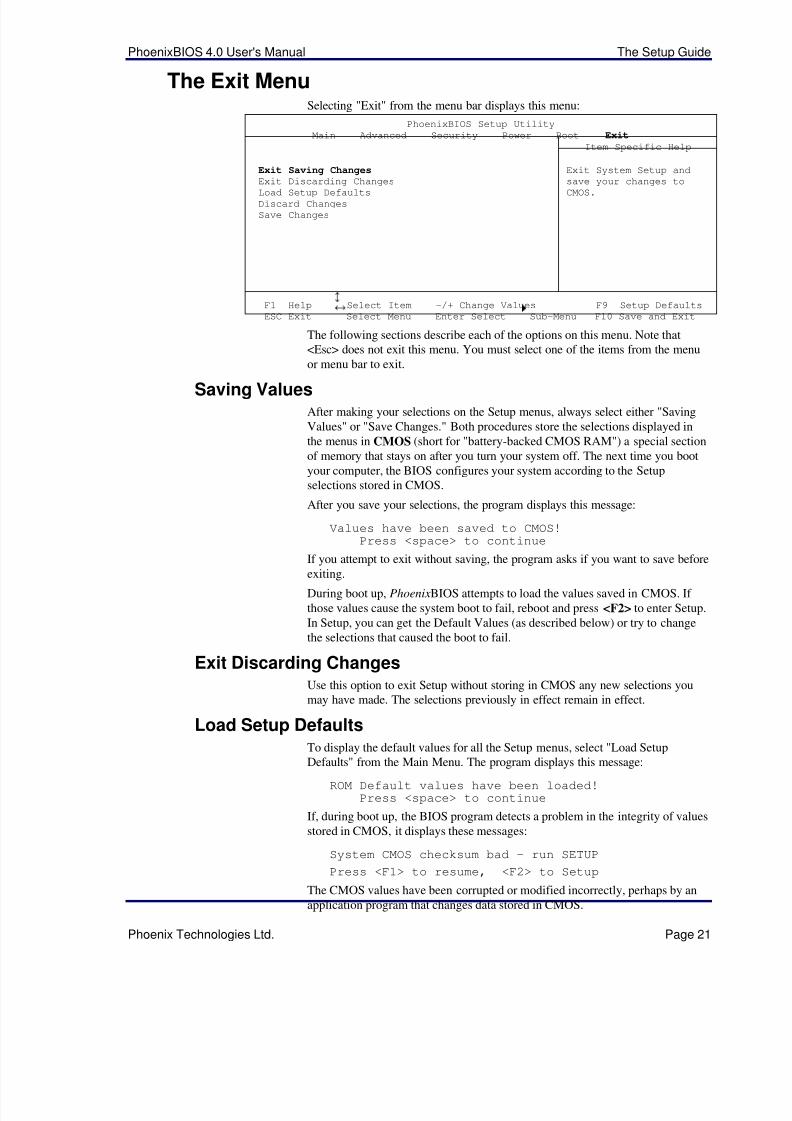
The Exit MenuSelecting "Exit" from the menu bar displays this menu:
PhoenixBIOS Setup Utility
Main Advanced Security Power Boot Exit
Item Specific Help
Exit Saving ChangesExit Discarding Changes
Load Setup DefaultsDiscard Changes
Save Changes
Exit System Setup and
save your changes to
CMOS.
F1 Help¦
Select Item -/+ Change Values F9 Setup Defaults
ESC Exit¥
Select Menu Enter Select
Sub-Menu F10 Save and Exit
The following sections describe each of the options on this menu. Note that<Esc> does not exit this menu. You must select one of the items from the menuor menu bar to exit.
Saving ValuesAfter making your selections on the Setup menus, always select either "SavingValues" or "Save Changes." Both procedures store the selections displayed inthe menus in CMOS (short for "battery-backed CMOS RAM") a special sectionof memory that stays on after you turn your system off. The next time you bootyour computer, the BIOS configures your system according to the Setupselections stored in CMOS.
After you save your selections, the program displays this message:
Values have been saved to CMOS!Press <space> to continue
If you attempt to exit without saving, the program asks if you want to save before
exiting.
During boot up, PhoenixBIOS attempts to load the values saved in CMOS. If those values cause the system boot to fail, reboot and press <F2> to enter Setup.In Setup, you can get the Default Values (as described below) or try to changethe selections that caused the boot to fail.
Exit Discarding ChangesUse this option to exit Setup without storing in CMOS any new selections youmay have made. The selections previously in effect remain in effect.
Load Setup DefaultsTo display the default values for all the Setup menus, select "Load Setup
Defaults" from the Main Menu. The program displays this message:
ROM Default values have been loaded!Press <space> to continue
If, during boot up, the BIOS program detects a problem in the integrity of valuesstored in CMOS, it displays these messages:
System CMOS checksum bad - run SETUP
Press <F1> to resume, <F2> to Setup
The CMOS values have been corrupted or modified incorrectly, perhaps by anapplication program that changes data stored in CMOS.

5/14/2018 PhoenixBIOS4_rev6UserMan - slidepdf.com
http://slidepdf.com/reader/full/phoenixbios4rev6userman 26/88
The Setup Guide PhoenixBIOS 4.0 User's Manual
Page 22 Phoenix Technologies Ltd.
Press <F1> to resume the boot or <F2> to run Setup with the ROM defaultvalues already loaded into the menus. You can make other changes before savingthe values to CMOS.
Discard ChangesIf, during a Setup Session, you change your mind about changes you have madeand have not yet saved the values to CMOS, you can restore the values youpreviously saved to CMOS.
Selecting “Discard Changes” on the Exit menu updates all the selections anddisplays this message:
CMOS values have been loaded!Press <space> to continue
Save ChangesSelecting “Save Changes” saves all the selections without exiting Setup. You canreturn to the other menus if you want to review and change your selections.

5/14/2018 PhoenixBIOS4_rev6UserMan - slidepdf.com
http://slidepdf.com/reader/full/phoenixbios4rev6userman 27/88
PhoenixBIOS 4.0 User's Manual The Setup Guide
Phoenix Technologies Ltd. Page 23
PhoenixBIOS Messages
The following is a list of the messages that the BIOS can display. Most of themoccur during POST. Some of them display information about a hardware device,e.g., the amount of memory installed. Others may indicate a problem with adevice, such as the way it has been configured. Following the list areexplanations of the messages and remedies for reported problems.
*If your system displays one of the messages marked below with an asterisk (*),write down the message and contact your dealer. If your system fails after youmake changes in the Setup menus, reset the computer, enter Setup and installSetup defaults or correct the error.
0200 Failure Fixed Disk Fixed disk is not working or not configured properly. Check to see if fixeddisk is attached properly. Run Setup. Find out if the fixed-disk type iscorrectly identified.
0210 Stuck key Stuck key on keyboard.
0211 Keyboard error Keyboard not working.
*0212 Keyboard Controller Failed Keyboard controller failed test. May require replacing keyboard controller.
0213 Keyboard locked - Unlock key switch Unlock the system to proceed.
0220 Monitor type does not match CMOS - Run SETUP Monitor type not correctly identified in Setup
*0230 Shadow Ram Failed at offset: nnnn Shadow RAM failed at offset nnnn of the 64k block at which the errorwas detected.
*0231 System RAM Failed at offset: nnnn System RAM failed at offset nnnn of in the 64k block at which the errorwas detected.
*0232 Extended RAM Failed at offset: nnnn Extended memory notworking or not configured properly at offset nnnn.
0250 System battery is dead - Replace and run SETUP The CMOS clock battery indicator shows the battery is dead. Replace the
battery and run Setup to reconfigure the system. 0251 System CMOS checksum bad - Default configuration used System CMOS has been corrupted or modified incorrectly, perhaps by anapplication program that changes data stored in CMOS. The BIOSinstalled Default Setup Values. If you do not want these values, enter Setupand enter your own values. If the error persists, check the system batteryor contact your dealer.
*0260 System timer error The timer test failed. Requires repair of system board.
*0270 Real time clock error Real-Time Clock fails BIOS hardware test.May require board repair.
0271 Check date and time settings BIOS found date or time out of range and reset the Real-Time Clock. May require setting legal date (1991-2099).
0280 Previous boot incomplete - Default configuration used
Previous POST did not complete successfully. POST loads default valuesand offers to run Setup. If the failure was caused by incorrect values andthey are not corrected, the next boot will likely fail. On systems withcontrol of wait states, improper Setup settings can also terminate POSTand cause this error on the next boot. Run Setup and verify that the wait-state configuration is correct. This error is cleared the next time the systemis booted.
0281 Memory Size found by POST differed from CMOS Memory size found by POST differed from CMOS.
02B0 Diskette drive A error
02B1 Diskette drive B error Drive A: or B: is present but fails the BIOS POST diskette tests. Check to
5/14/2018 PhoenixBIOS4_rev6UserMan - slidepdf.com
http://slidepdf.com/reader/full/phoenixbios4rev6userman 28/88
The Setup Guide PhoenixBIOS 4.0 User's Manual
Page 24 Phoenix Technologies Ltd.
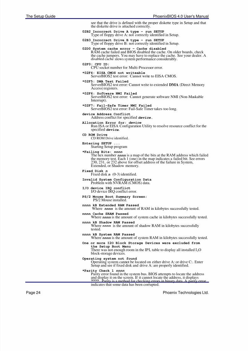
see that the drive is defined with the proper diskette type in Setup and thatthe diskette drive is attached correctly.
02B2 Incorrect Drive A type - run SETUP Type of floppy drive A: not correctly identified in Setup.
02B3 Incorrect Drive B type - run SETUP Type of floppy drive B: not correctly identified in Setup.
02D0 System cache error - Cache disabled RAM cache failed and BIOS disabled the cache. On older boards, check the cache jumpers. You may have to replace the cache. See your dealer. A
disabled cache slows system performance considerably.02F0: CPU ID:
CPU socket number for Multi-Processor error.
*02F4: EISA CMOS not writeable ServerBIOS2 test error: Cannot write to EISA CMOS.
*02F5: DMA Test FailedServerBIOS2 test error: Cannot write to extended DMA (Direct MemoryAccess) registers.
*02F6: Software NMI Failed ServerBIOS2 test error: Cannot generate software NMI (Non-MaskableInterrupt).
*02F7: Fail-Safe Timer NMI FailedServerBIOS2 test error: Fail-Safe Timer takes too long.
device Address Conflict
Address conflict for specifieddevice.
Allocation Error for: device
Run ISA or EISA Configuration Utility to resolve resource conflict for thespecified devic e.
CD ROM Drive CD ROM Drive identified.
Entering SETUP ... Starting Setup program
*Failing Bits: nnnn
The hex number nnnn is a map of the bits at the RAM address which failedthe memory test. Each 1 (one) in the map indicates a failed bit. See errors230, 231, or 232 above for offset address of the failure in System,Extended, or Shadow memory.
Fixed Disk n Fixed disk n (0-3) identified.
Invalid System Configuration Data Problem with NVRAM (CMOS) data.
I/O device IRQ conflict I/O device IRQ conflict error.
PS/2 Mouse Boot Summary Screen:PS/2 Mouse installed.
nnnn kB Extended RAM Passed Where nnnn is the amount of RAM in kilobytes successfully tested.
nnnn Cache SRAM Passed Where nnnn is the amount of system cache in kilobytes successfully tested.
nnnn kB Shadow RAM Passed Where nnnn is the amount of shadow RAM in kilobytes successfullytested.
nnnn kB System RAM Passed
Where nnnn is the amount of system RAM in kilobytes successfully tested. One or more I2O Block Storage Devices were excluded from
the Setup Boot Menu There was not enough room in the IPL table to display all installed I2Oblock-storage devices.
Operating system not found Operating system cannot be located on either drive A: or drive C:. EnterSetup and see if fixed disk and drive A: are properly identified.
*Parity Check 1 nnnn Parity error found in the system bus. BIOS attempts to locate the addressand display it on the screen. If it cannot locate the address, it displays????. Parity is a method for checking errors in binary data. A parity errorindicates that some data has been corrupted.
5/14/2018 PhoenixBIOS4_rev6UserMan - slidepdf.com
http://slidepdf.com/reader/full/phoenixbios4rev6userman 29/88
PhoenixBIOS 4.0 User's Manual The Setup Guide
Phoenix Technologies Ltd. Page 25
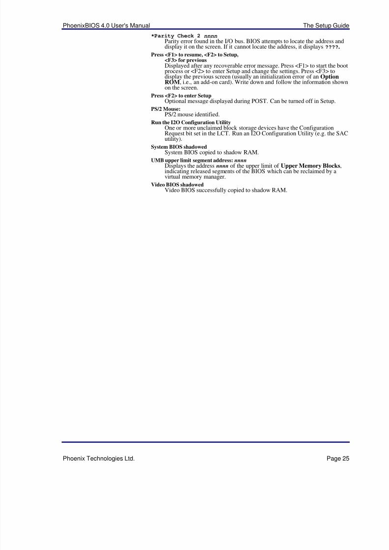
*Parity Check 2 nnnn Parity error found in the I/O bus. BIOS attempts to locate the address anddisplay it on the screen. If it cannot locate the address, it displays ????.
Press <F1> to resume, <F2> to Setup,<F3> for previous Displayed after any recoverable error message. Press <F1> to start the bootprocess or <F2> to enter Setup and change the settings. Press <F3> todisplay the previous screen (usually an initialization error of an OptionROM, i.e., an add-on card). Write down and follow the information shownon the screen.
Press <F2> to enter SetupOptional message displayed during POST. Can be turned off in Setup.
PS/2 Mouse: PS/2 mouse identified.
Run the I2O Configuration Utility One or more unclaimed block storage devices have the ConfigurationRequest bit set in the LCT. Run an I2O Configuration Utility (e.g. the SACutility).
System BIOS shadowed System BIOS copied to shadow RAM.
UMB upper limit segment address: nnnn Displays the address nnnn of the upper limit of Upper Memory Blocks,indicating released segments of the BIOS which can be reclaimed by avirtual memory manager.
Video BIOS shadowed Video BIOS successfully copied to shadow RAM.
5/14/2018 PhoenixBIOS4_rev6UserMan - slidepdf.com
http://slidepdf.com/reader/full/phoenixbios4rev6userman 30/88
Phoenix Technologies, Ltd. Page 26
2Boot Utilities Phoenix Boot Utilities are:
• Phoenix QuietBoot™
• Phoenix MultiBoot™
Phoenix QuietBoot displays a graphic illustration rather than the traditionalPOST messages while keeping you informed of diagnostic problems.
Phoenix MultiBoot is a boot screen that displays a selection of boot devicesfrom which you can boot your operating system.
Phoenix QuietBootRight after you turn on or reset the computer, Phoenix QuietBoot displays theQuietBoot Screen, a graphic illustration created by the computer manufacturerinstead of the text-based POST screen, which displays a number of PCdiagnostic messages.
To exit the QuietBoot screen and run Setup, display the MultiBoot menu, orsimply display the PC diagnostic messages, you can simply press one of the hotkeys described below.
The QuietBoot Screen stays up until just before the operating system loadsunless:
1. You press <Esc> to display the POST screen.
2. You press <F2> to enter Setup.
3. POST issues an error message.4. The BIOS or an option ROM requests keyboard input.
The following explains each of these situations.
Press <ESC>Pressing <Esc> switches to the POST screen and takes one of two actions:
1. If MultiBoot is installed, the boot process continues with the text-based
POST screen until the end of POST, and then displays the Boot First
Menu, with these options:
a. Load the operating system from a boot device of your choice.
b. Enter Setup.
c. Exit the Boot First Menu (with <Esc>) and load the operating system
from the boot devices in the order specified in Setup.2. If MultiBoot is not installed, the boot process continues as usual.
Press <F2>Pressing <F2> at any time during POST switches to the POST screen (if notalready displayed) and enters Setup.
POST ErrorWhenever POST detects a non-fatal error, QuietBoot switches to the POSTscreen and displays the errors. It then displays this message:
5/14/2018 PhoenixBIOS4_rev6UserMan - slidepdf.com
http://slidepdf.com/reader/full/phoenixbios4rev6userman 31/88
PhoenixBIOS 4.0 User's Manual Boot Utilities
Phoenix Technologies Ltd. Page 27
Press <F1> to resume, <F2> to Setup
Press <F1> to continue with the boot. Press <F2> if you want to correct the errorin Setup.
Keyboard Input RequestIf the BIOS or an Option ROM (add-on card) requests keyboard input,QuietBoot switches over to the POST screen and the Option ROM displays
prompts for entering the information. POST continues from there with theregular POST screen.
Phoenix MultiBootPhoenix MultiBoot expands your boot options by letting you choose your bootdevice, which could be a hard disk, floppy disk, or CD ROM. You can selectyour boot device in Setup, or you can choose a different device each time youboot during POST by selecting your boot device in The Boot First Menu.
MultiBoot consists of:
• The Setup Boot Menu
• The Boot First Menu
See the Setup Boot menu on p. 11. The following describes the Boot First Menu.
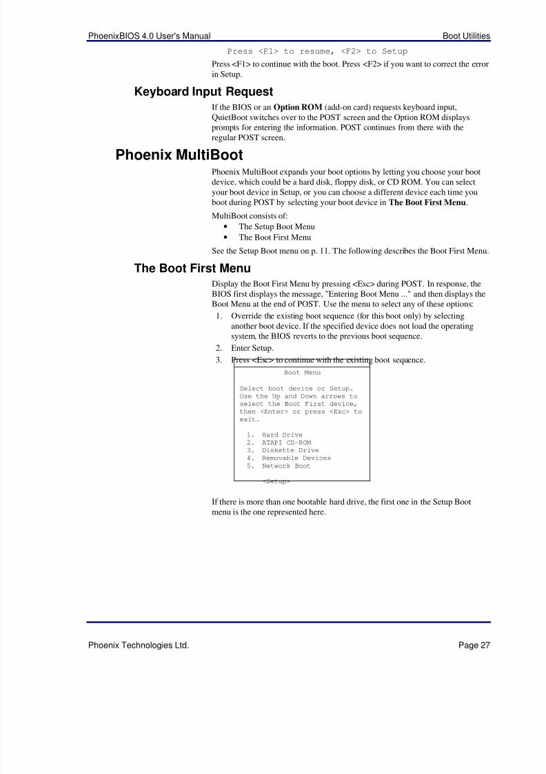
The Boot First MenuDisplay the Boot First Menu by pressing <Esc> during POST. In response, theBIOS first displays the message, "Entering Boot Menu ..." and then displays theBoot Menu at the end of POST. Use the menu to select any of these options:
1. Override the existing boot sequence (for this boot only) by selectinganother boot device. If the specified device does not load the operatingsystem, the BIOS reverts to the previous boot sequence.
2. Enter Setup.
3. Press <Esc> to continue with the existing boot sequence.
Boot Menu
Select boot device or Setup.
Use the Up and Down arrows to
select the Boot First device,
then <Enter> or press <Esc> to
exit.
1. Hard Drive
2. ATAPI CD-ROM
3. Diskette Drive
4. Removable Devices
5. Network Boot
<Setup>
If there is more than one bootable hard drive, the first one in the Setup Bootmenu is the one represented here.
5/14/2018 PhoenixBIOS4_rev6UserMan - slidepdf.com
http://slidepdf.com/reader/full/phoenixbios4rev6userman 32/88
Phoenix Technologies, Ltd. Page 28
3Phoenix Phlash Phoenix Phlash gives you the ability to update your BIOS from a floppy disk without having to install a new ROM BIOS chip.
Phoenix Phlash is a utility for "flashing" (copying) a BIOS to the Flash ROMinstalled on your computer from a floppy disk. A Flash ROM is a Read-OnlyMemory chip that you can write to using a special method called "flashing." UsePhoenix Phlash for the following tasks:
Update the current BIOS with a new version.
Restore a BIOS when it has become corrupted.
Installation Phoenix Phlash is shipped on a floppy disk with your computer as a compressedfile called CRISDISK.ZIP that contains the following files:
CRISDISK.BAT Executable file for creating the Crisis RecoveryDiskette.
PHLASH.EXE Programs the flash ROM.
PLATFORM.BIN Performs platform-dependent functions.
BIOS.ROM Actual BIOS image to be programmed into flash ROM.
MINIDOS.SYS Allows the system to boot in Crisis Recovery Mode.
MAKEBOOT.EXE Creates the custom boot sector on the Crisis RecoveryDiskette.
To install Phoenix Phlash on your hard disk, follow this simple procedure:
1. Insert the distribution diskette into drive A:2. Unzip the contents of CRISDISK.ZIP into a local directory, presumablyC:\PHLASH.
3. Store the distribution diskette in a safe place.
Create the Crisis Recovery DisketteIf the OEM or dealer from whom you purchased your system has not providedyou with one, then you should create a Crisis Recovery Diskette before you usethe Phlash utility. If you are unable to boot your system and successfully load theOperating System, the BIOS may have been corrupted, in which case you willhave to use the Crisis Recovery Diskette to reboot your system. There areseveral methods that you can use to create the Crisis Recovery Diskette. Belowis one recommended procedure.
1. Be sure you have successfully installed the Phlash Utility onto your harddisk.
2. Insert a clean diskette into drive A: or B:
3. From the local directory, enter the following:
CRISDISK [drive]:
where [drive] is the letter of the drive into which you inserted the diskette.For help, type /? or /h.
CRISDISK.BAT formats the diskette, then copies MINIDOS.SYS,VGABIOS.EXE (if available), PHLASH.EXE, PLATFORM.BIN andBIOS.ROM to the diskette, and creates the required custom boot sector.
5/14/2018 PhoenixBIOS4_rev6UserMan - slidepdf.com
http://slidepdf.com/reader/full/phoenixbios4rev6userman 33/88
PhoenixBIOS 4.0 User's Manual Boot Utilities
Phoenix Technologies Ltd. Page 29
4. Write protect and label the Crisis Recovery Diskette.
NOTE: You can only supply a volume label after the Crisis Recovery Diskettehas been formatted and the necessary files copied because MINIDOS.SYS mustoccupy the first directory entry for the diskette to boot properly.
Updating the Crisis Recovery DisketteIf the BIOS image (BIOS.ROM) changes due to an update or bug fix, you can
easily update the Crisis Recovery Diskette. Simply copy the new BIOS.ROMimage onto the Crisis Recovery Diskette. No further action is necessary.
Executing Phoenix PhlashYou can run Phoenix Phlash in one of two modes:
Command Line Mode
Crisis Recovery Mode
WARNING! For your own protection, be sure you have a Crisis RecoveryDiskette ready to use before executing Phlash.
Command Line Mode
Use this mode to update or replace your current BIOS. To execute Phlash in thismode, move to the directory into which you have installed Phoenix Phlash andtype the following:
phlash
Phoenix Phlash will automatically update or replace the current BIOS with theone which your OEM or dealer supplies you.
Phlash may fail if your system is using memory managers, in which case theutility displays the following message:
Cannot flash when memory managers are present.
If you see this message after you execute Phlash, you must disable the memorymanager on your system. To do so, follow the instructions in the following
sections.Disabling Memory Managers
To avoid failure when flashing, you must disable the memory managers that loadfrom CONFIG.SYS and AUTOEXEC.BAT. There are two recommendedprocedures for disabling the memory managers. One consists of pressing the<F5> key (only if you are using DOS 5.0 or above), and the other requires thecreation of a boot diskette.
DOS 5.0 (or later version)
For DOS 5.0 and later, follow the two steps below to disable any memorymanagers on your system. If you are not using at least DOS 5.0, then you mustcreate a boot diskette to bypass any memory managers (See Create a BootDiskette, below).
1. Boot DOS 5.0 or later version. (In Windows 95, at the boot option screen,choose Option 8, "Boot to a previous version of DOS.")
2. When DOS displays the “Starting MS-DOS” message, press <F5>.
After you press <F5>, DOS bypasses the CONFIG.SYS and AUTOEXEC.BATfiles, and therefore does not load any memory managers.
You can now execute Phlash.
Create a Boot Diskette
To bypass memory managers in DOS versions previous to 5.0, follow thisrecommended procedure:
5/14/2018 PhoenixBIOS4_rev6UserMan - slidepdf.com
http://slidepdf.com/reader/full/phoenixbios4rev6userman 34/88
Phoenix Phlash PhoenixBIOS 4.0 User's Manual
Page 30 Phoenix Technologies Ltd.
1. Insert a diskette into your A: drive.
2. Enter the following from the command line:
Format A: /S
3. Reboot your system from the A: drive.
Your system will now boot without loading the memory managers, and you canthen execute Phlash.
NOTE: The boot diskette you create here is distinct from a Crisis Recovery
Diskette. See page 409 for details about creating the Crisis Recovery Diskette.
Crisis Recovery ModeYou should only have to operate Phoenix Phlash in this mode only if yoursystem does not boot the operating system when you turn on or reset yourcomputer. In these cases, the BIOS on the Flash ROM has probably beencorrupted. Boot your system with the Crisis Recovery Diskette taking thesesteps:
1. Insert the Crisis Recovery diskette (which your dealer supplied or one thatyou should have created from the instructions above) into drive A:.
2. Reset your computer, power off-on, or press <Ctrl> <Alt> <Del> to rebootthe system.
3. When your system reboots, Phoenix Phlash will restore the BIOS from thediskette and successfully boot the operating system.
5/14/2018 PhoenixBIOS4_rev6UserMan - slidepdf.com
http://slidepdf.com/reader/full/phoenixbios4rev6userman 35/88
Phoenix Technologies, Ltd. Page 31
4Programmer's Guide This chapter of the User's Manual gives application developers, programmers,and expert computer users a detailed description of the BIOS.
This chapter describes the following subjects:
• What is a ROM BIOS?
• System Hardware Requirements
• Fixed-Disk Tables
• PhoenixBIOS Function Keys
• POST Errors
• Run-Time Services
What is a ROM BIOS?This section briefly explains the function of a BIOS in managing the specialfeatures of your system.
A ROM BIOS (Basic Input/Output System) is a set of programs permanently
stored in a ROM (Read-Only Memory) chip located on the computermotherboard. These programs micro-manage the hardware devices installed onyour computer. When you turn on your computer, the ROM BIOS initializes andtests these devices. During run-time, the ROM BIOS provides the OperatingSystem and application programs with access to these devices. You can also usethe BIOS Setup program to change your computer's hardware or behavior.
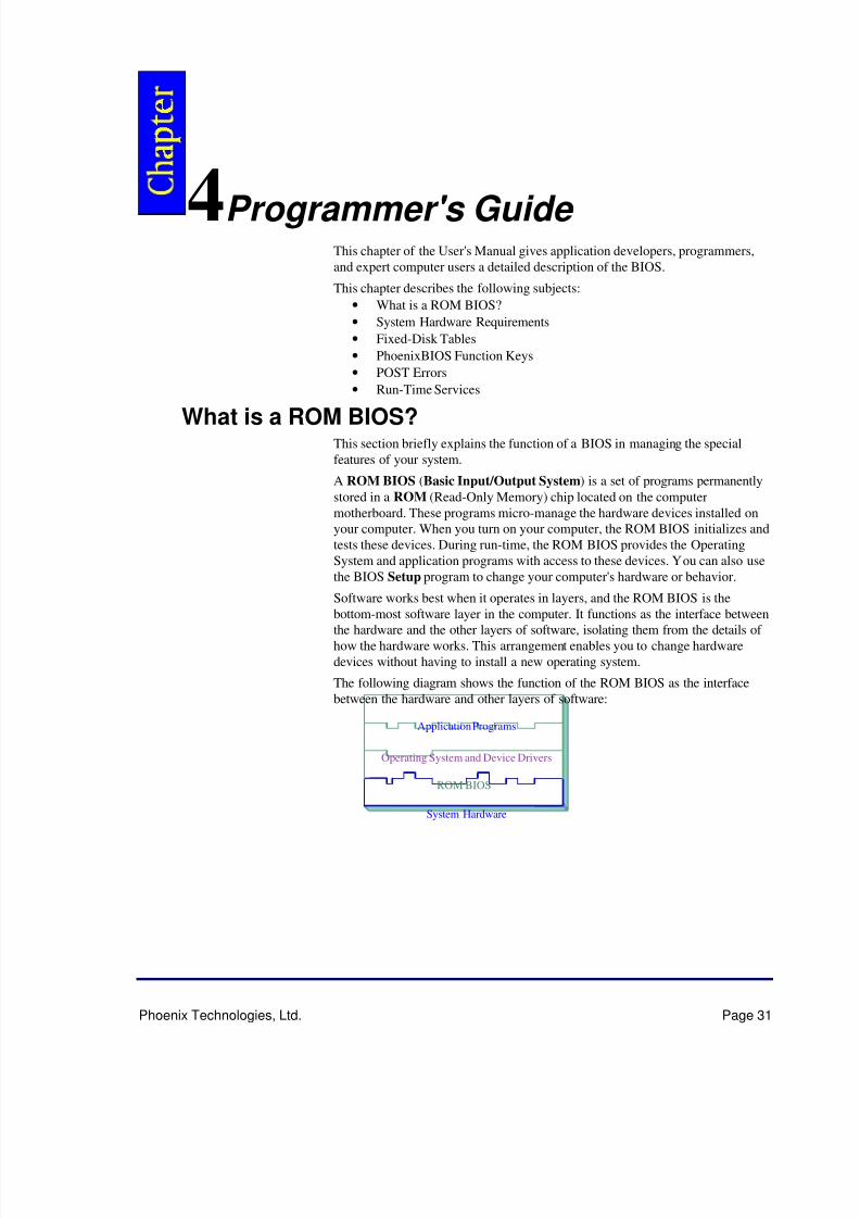
Software works best when it operates in layers, and the ROM BIOS is the
bottom-most software layer in the computer. It functions as the interface betweenthe hardware and the other layers of software, isolating them from the details of how the hardware works. This arrangement enables you to change hardwaredevices without having to install a new operating system.
The following diagram shows the function of the ROM BIOS as the interfacebetween the hardware and other layers of software:
Application Programs
Operating System and Device Drivers
ROM BIOS
System Hardware
5/14/2018 PhoenixBIOS4_rev6UserMan - slidepdf.com
http://slidepdf.com/reader/full/phoenixbios4rev6userman 36/88
Programmer’s Guide PhoenixBIOS 4.0 User's Manual
Page 32 Phoenix Technologies Ltd.
ROM BIOS FunctionsThe PhoenixBIOS software performs these functions:
The Setup Program Using the Setup program, you can install,configure, and optimize the hardwaredevices on your system (clock, memory,disk drives, etc.).
Initialize Hardware at Boot At power-on or reset, perform Power-OnSelf Test (POST) routines to test system
resources and run the operating system.Run-Time Routines Basic hardware routines that can be called
from DOS and Windows applications.
Initialize and Configure the computerThe first job of a ROM BIOS is to initialize and configure the computerhardware when you turn on your computer (system boot). The BIOS runs aseries of complex programs called the Power On Self Test (POST), whichperforms a number of tasks, including:
• Test Random Access Memory (RAM)
• Conduct an inventory of the hardware devices installed in the computer
• Configure hard and floppy disks, keyboard, monitor, and serial andparallel ports
• Configure other devices installed in the computer such as CD-ROMdrives and sound cards
• Initialize computer hardware required for computer features such as Plugand Play and Power Management
• Run Setup if requested
• Load and run the Operating System such as DOS, OS/2, UNIX, orWindows 95 or NT.
BIOS ServicesThe second task of the ROM BIOS is to provide the Operating System, devicedrivers, and application programs with access to the system hardware. It
performs this task with a set of program routines called BIOS Services, which
are loaded into high memory at boot time.The number of BIOS Services is always changing. The BIOS Services of PhoenixBIOS 4.05 provide precise control of hardware devices such as disk drives, which require careful management and exhaustive checking for errors.They also help manage new computer features such as Power Management, Plugand Play, and MultiBoot.
System Hardware RequirementsPhoenixBIOS 4.0 requires the following hardware components on themotherboard:
System Board Requirements
1. CPU (486 or later)
2. AT-compatible and MC146818 RTC-compatible chipset.3. AT or PS/2-compatible Keyboard controller4. At least 1 MB of system RAM
The Power On Self Test (POST) of the BIOS initializes additional ROM BIOSextensions (Option ROMs) if they are accessible in the proper format. Therequirements are:
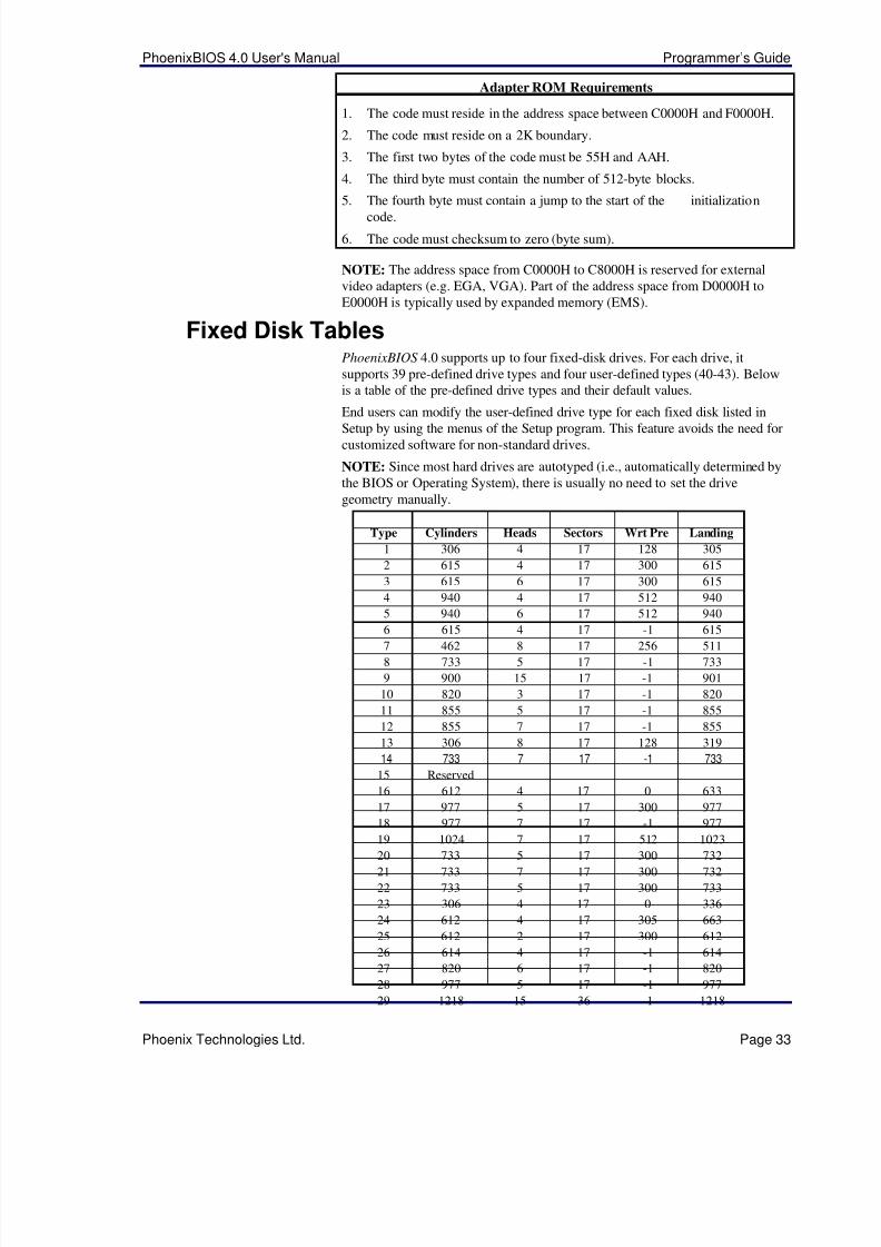
5/14/2018 PhoenixBIOS4_rev6UserMan - slidepdf.com
http://slidepdf.com/reader/full/phoenixbios4rev6userman 37/88
PhoenixBIOS 4.0 User's Manual Programmer’s Guide
Phoenix Technologies Ltd. Page 33
Adapter ROM Requirements
1. The code must reside in the address space between C0000H and F0000H.
2. The code must reside on a 2K boundary.
3. The first two bytes of the code must be 55H and AAH.
4. The third byte must contain the number of 512-byte blocks.
5. The fourth byte must contain a jump to the start of the initializationcode.
6. The code must checksum to zero (byte sum).
NOTE: The address space from C0000H to C8000H is reserved for externalvideo adapters (e.g. EGA, VGA). Part of the address space from D0000H toE0000H is typically used by expanded memory (EMS).
Fixed Disk TablesPhoenixBIOS 4.0 supports up to four fixed-disk drives. For each drive, itsupports 39 pre-defined drive types and four user-defined types (40-43). Belowis a table of the pre-defined drive types and their default values.
End users can modify the user-defined drive type for each fixed disk listed inSetup by using the menus of the Setup program. This feature avoids the need forcustomized software for non-standard drives.
NOTE: Since most hard drives are autotyped (i.e., automatically determined bythe BIOS or Operating System), there is usually no need to set the drivegeometry manually.
Type Cylinders Heads Sectors Wrt Pre Landing
1 306 4 17 128 305
2 615 4 17 300 615
3 615 6 17 300 615
4 940 4 17 512 940
5 940 6 17 512 940
6 615 4 17 -1 6157 462 8 17 256 511
8 733 5 17 -1 733
9 900 15 17 -1 901
10 820 3 17 -1 820
11 855 5 17 -1 855
12 855 7 17 -1 855
13 306 8 17 128 319
14 733 7 17 -1 733
15 Reserved
16 612 4 17 0 633
17 977 5 17 300 977
18 977 7 17 -1 977
19 1024 7 17 512 102320 733 5 17 300 732
21 733 7 17 300 732
22 733 5 17 300 733
23 306 4 17 0 336
24 612 4 17 305 663
25 612 2 17 300 612
26 614 4 17 -1 614
27 820 6 17 -1 820
28 977 5 17 -1 977
29 1218 15 36 -1 1218
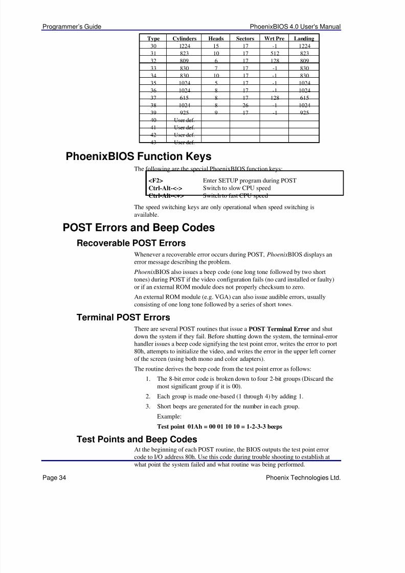
5/14/2018 PhoenixBIOS4_rev6UserMan - slidepdf.com
http://slidepdf.com/reader/full/phoenixbios4rev6userman 38/88
Programmer’s Guide PhoenixBIOS 4.0 User's Manual
Page 34 Phoenix Technologies Ltd.
Type Cylinders Heads Sectors Wrt Pre Landing
30 1224 15 17 -1 1224
31 823 10 17 512 823
32 809 6 17 128 809
33 830 7 17 -1 830
34 830 10 17 -1 830
35 1024 5 17 -1 1024
36 1024 8 17 -1 1024
37 615 8 17 128 61538 1024 8 26 -1 1024
39 925 9 17 -1 925
40 User def.
41 User def.
42 User def.
43 User def.
PhoenixBIOS Function KeysThe following are the special PhoenixBIOS function keys:
<F2> Enter SETUP program during POST
Ctrl-Alt-<-> Switch to slow CPU speed
Ctrl-Alt-<+> Switch to fast CPU speed
The speed switching keys are only operational when speed switching isavailable.
POST Errors and Beep Codes
Recoverable POST ErrorsWhenever a recoverable error occurs during POST, PhoenixBIOS displays anerror message describing the problem.
PhoenixBIOS also issues a beep code (one long tone followed by two shorttones) during POST if the video configuration fails (no card installed or faulty)or if an external ROM module does not properly checksum to zero.
An external ROM module (e.g. VGA) can also issue audible errors, usuallyconsisting of one long tone followed by a series of short tones.
Terminal POST ErrorsThere are several POST routines that issue a POST Terminal Error and shutdown the system if they fail. Before shutting down the system, the terminal-errorhandler issues a beep code signifying the test point error, writes the error to port80h, attempts to initialize the video, and writes the error in the upper left cornerof the screen (using both mono and color adapters).
The routine derives the beep code from the test point error as follows:
1. The 8-bit error code is broken down to four 2-bit groups (Discard the
most significant group if it is 00).2. Each group is made one-based (1 through 4) by adding 1.
3. Short beeps are generated for the number in each group.
Example:
Test point 01Ah = 00 01 10 10 = 1-2-3-3 beeps
Test Points and Beep CodesAt the beginning of each POST routine, the BIOS outputs the test point errorcode to I/O address 80h. Use this code during trouble shooting to establish atwhat point the system failed and what routine was being performed.
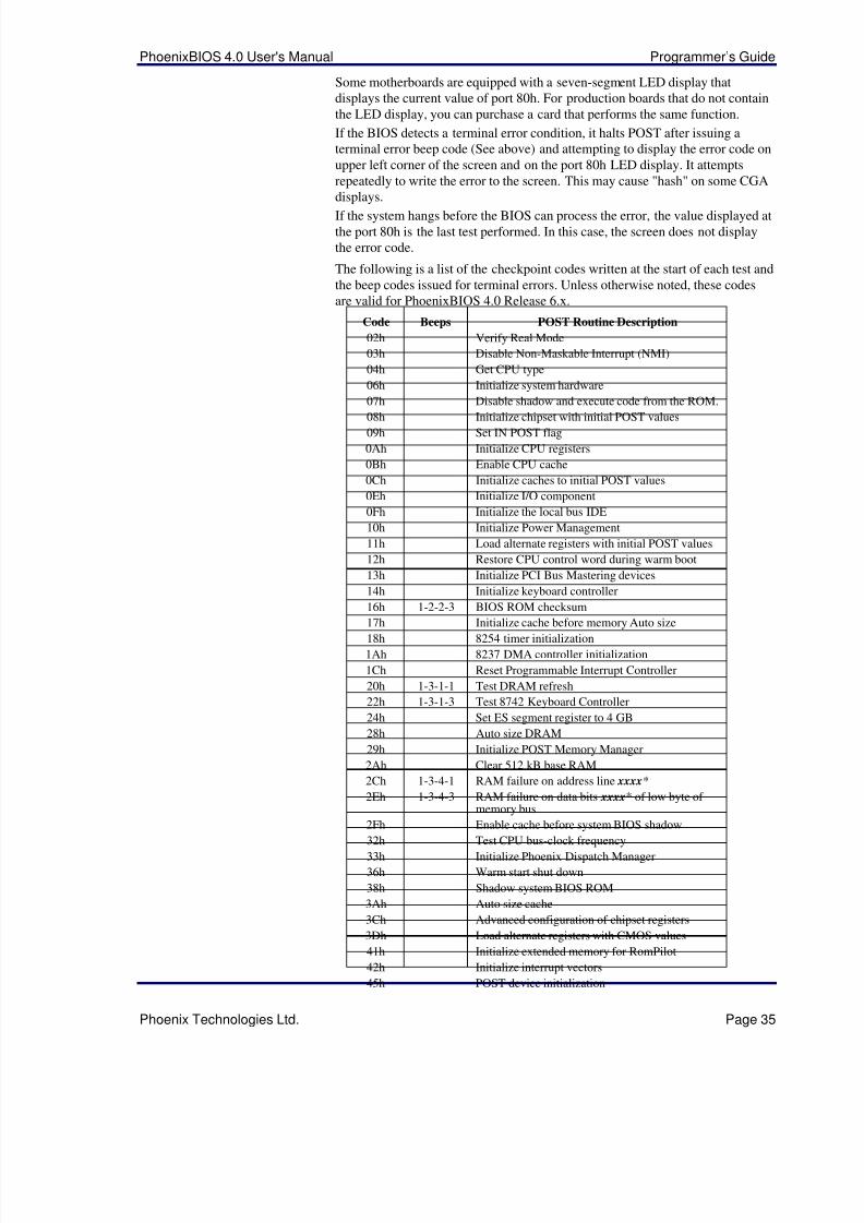
5/14/2018 PhoenixBIOS4_rev6UserMan - slidepdf.com
http://slidepdf.com/reader/full/phoenixbios4rev6userman 39/88
PhoenixBIOS 4.0 User's Manual Programmer’s Guide
Phoenix Technologies Ltd. Page 35
Some motherboards are equipped with a seven-segment LED display thatdisplays the current value of port 80h. For production boards that do not containthe LED display, you can purchase a card that performs the same function.
If the BIOS detects a terminal error condition, it halts POST after issuing aterminal error beep code (See above) and attempting to display the error code onupper left corner of the screen and on the port 80h LED display. It attemptsrepeatedly to write the error to the screen. This may cause "hash" on some CGAdisplays.
If the system hangs before the BIOS can process the error, the value displayed atthe port 80h is the last test performed. In this case, the screen does not displaythe error code.
The following is a list of the checkpoint codes written at the start of each test andthe beep codes issued for terminal errors. Unless otherwise noted, these codesare valid for PhoenixBIOS 4.0 Release 6.x.
Code Beeps POST Routine Description
02h Verify Real Mode
03h Disable Non-Maskable Interrupt (NMI)
04h Get CPU type
06h Initialize system hardware
07h Disable shadow and execute code from the ROM.
08h Initialize chipset with initial POST values09h Set IN POST flag
0Ah Initialize CPU registers
0Bh Enable CPU cache
0Ch Initialize caches to initial POST values
0Eh Initialize I/O component
0Fh Initialize the local bus IDE
10h Initialize Power Management
11h Load alternate registers with initial POST values
12h Restore CPU control word during warm boot
13h Initialize PCI Bus Mastering devices
14h Initialize keyboard controller
16h 1-2-2-3 BIOS ROM checksum
17h Initialize cache before memory Auto size18h 8254 timer initialization
1Ah 8237 DMA controller initialization
1Ch Reset Programmable Interrupt Controller
20h 1-3-1-1 Test DRAM refresh
22h 1-3-1-3 Test 8742 Keyboard Controller
24h Set ES segment register to 4 GB
28h Auto size DRAM
29h Initialize POST Memory Manager
2Ah Clear 512 kB base RAM
2Ch 1-3-4-1 RAM failure on address line xxxx*
2Eh 1-3-4-3 RAM failure on data bits xxxx* of low byte of memory bus
2Fh Enable cache before system BIOS shadow32h Test CPU bus-clock frequency
33h Initialize Phoenix Dispatch Manager
36h Warm start shut down
38h Shadow system BIOS ROM
3Ah Auto size cache
3Ch Advanced configuration of chipset registers
3Dh Load alternate registers with CMOS values
41h Initialize extended memory for RomPilot
42h Initialize interrupt vectors
45h POST device initialization
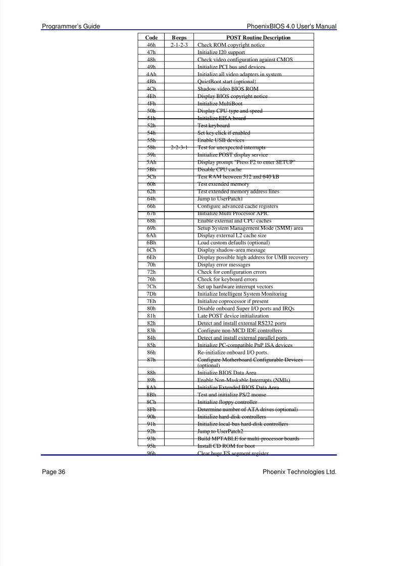
5/14/2018 PhoenixBIOS4_rev6UserMan - slidepdf.com
http://slidepdf.com/reader/full/phoenixbios4rev6userman 40/88
Programmer’s Guide PhoenixBIOS 4.0 User's Manual
Page 36 Phoenix Technologies Ltd.
Code Beeps POST Routine Description
46h 2-1-2-3 Check ROM copyright notice
47h Initialize I20 support
48h Check video configuration against CMOS
49h Initialize PCI bus and devices
4Ah Initialize all video adapters in system
4Bh QuietBoot start (optional)
4Ch Shadow video BIOS ROM
4Eh Display BIOS copyright notice4Fh Initialize MultiBoot
50h Display CPU type and speed
51h Initialize EISA board
52h Test keyboard
54h Set key click if enabled
55h Enable USB devices
58h 2-2-3-1 Test for unexpected interrupts
59h Initialize POST display service
5Ah Display prompt "Press F2 to enter SETUP"
5Bh Disable CPU cache
5Ch Test RAM between 512 and 640 kB
60h Test extended memory
62h Test extended memory address lines64h Jump to UserPatch1
66h Configure advanced cache registers
67h Initialize Multi Processor APIC
68h Enable external and CPU caches
69h Setup System Management Mode (SMM) area
6Ah Display external L2 cache size
6Bh Load custom defaults (optional)
6Ch Display shadow-area message
6Eh Display possible high address for UMB recovery
70h Display error messages
72h Check for configuration errors
76h Check for keyboard errors
7Ch Set up hardware interrupt vectors7Dh Initialize Intelligent System Monitoring
7Eh Initialize coprocessor if present
80h Disable onboard Super I/O ports and IRQs
81h Late POST device initialization
82h Detect and install external RS232 ports
83h Configure non-MCD IDE controllers
84h Detect and install external parallel ports
85h Initialize PC-compatible PnP ISA devices
86h Re-initialize onboard I/O ports.
87h Configure Motherboard Configurable Devices(optional)
88h Initialize BIOS Data Area
89h Enable Non-Maskable Interrupts (NMIs)
8Ah Initialize Extended BIOS Data Area
8Bh Test and initialize PS/2 mouse
8Ch Initialize floppy controller
8Fh Determine number of ATA drives (optional)
90h Initialize hard-disk controllers
91h Initialize local-bus hard-disk controllers
92h Jump to UserPatch2
93h Build MPTABLE for multi-processor boards
95h Install CD ROM for boot
96h Clear huge ES segment register
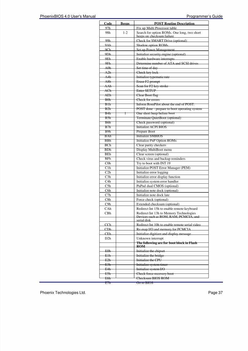
5/14/2018 PhoenixBIOS4_rev6UserMan - slidepdf.com
http://slidepdf.com/reader/full/phoenixbios4rev6userman 41/88
PhoenixBIOS 4.0 User's Manual Programmer’s Guide
Phoenix Technologies Ltd. Page 37
Code Beeps POST Routine Description
97h Fix up Multi Processor table
98h 1-2 Search for option ROMs. One long, two shortbeeps on checksum failure
99h Check for SMART Drive (optional)
9Ah Shadow option ROMs
9Ch Set up Power Management
9Dh Initialize security engine (optional)
9Eh Enable hardware interrupts9Fh Determine number of ATA and SCSI drives
A0h Set time of day
A2h Check key lock
A4h Initialize typematic rate
A8h Erase F2 prompt
AAh Scan for F2 key stroke
ACh Enter SETUP
AEh Clear Boot flag
B0h Check for errors
B1h Inform RomPilot about the end of POST.
B2h POST done - prepare to boot operating system
B4h 1 One short beep before boot
B5h Terminate QuietBoot (optional)B6h Check password (optional)
B7h Initialize ACPI BIOS
B9h Prepare Boot
BAh Initialize SMBIOS
BBh Initialize PnP Option ROMs
BCh Clear parity checkers
BDh Display MultiBoot menu
BEh Clear screen (optional)
BFh Check virus and backup reminders
C0h Try to boot with INT 19
C1h Initialize POST Error Manager (PEM)
C2h Initialize error logging
C3h Initialize error display functionC4h Initialize system error handler
C5h PnPnd dual CMOS (optional)
C6h Initialize note dock (optional)
C7h Initialize note dock late
C8h Force check (optional)
C9h Extended checksum (optional)
CAh Redirect Int 15h to enable remote keyboard
CBh Redirect Int 13h to Memory TechnologiesDevices such as ROM, RAM, PCMCIA, andserial disk
CCh Redirect Int 10h to enable remote serial video
CDh Re-map I/O and memory for PCMCIA
CEh Initialize digitizer and display message
D2h Unknown interruptThe following are for boot block in FlashROM
E0h Initialize the chipset
E1h Initialize the bridge
E2h Initialize the CPU
E3h Initialize system timer
E4h Initialize system I/O
E5h Check force recovery boot
E6h Checksum BIOS ROM
E7h Go to BIOS
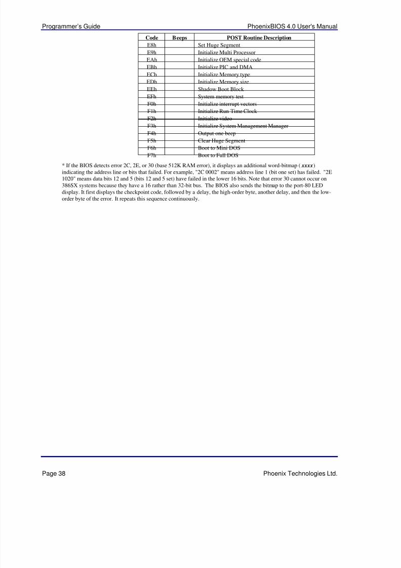
5/14/2018 PhoenixBIOS4_rev6UserMan - slidepdf.com
http://slidepdf.com/reader/full/phoenixbios4rev6userman 42/88
Programmer’s Guide PhoenixBIOS 4.0 User's Manual
Page 38 Phoenix Technologies Ltd.
Code Beeps POST Routine Description
E8h Set Huge Segment
E9h Initialize Multi Processor
EAh Initialize OEM special code
EBh Initialize PIC and DMA
ECh Initialize Memory type
EDh Initialize Memory size
EEh Shadow Boot Block
EFh System memory testF0h Initialize interrupt vectors
F1h Initialize Run Time Clock
F2h Initialize video
F3h Initialize System Management Manager
F4h Output one beep
F5h Clear Huge Segment
F6h Boot to Mini DOS
F7h Boot to Full DOS
* If the BIOS detects error 2C, 2E, or 30 (base 512K RAM error), it displays an additional word-bitmap ( xxxx)indicating the address line or bits that failed. For example, "2C 0002" means address line 1 (bit one set) has failed. "2E1020" means data bits 12 and 5 (bits 12 and 5 set) have failed in the lower 16 bits. Note that error 30 cannot occur on386SX systems because they have a 16 rather than 32-bit bus. The BIOS also sends the bitmap to the port-80 LED
display. It first displays the checkpoint code, followed by a delay, the high-order byte, another delay, and then the low-order byte of the error. It repeats this sequence continuously.
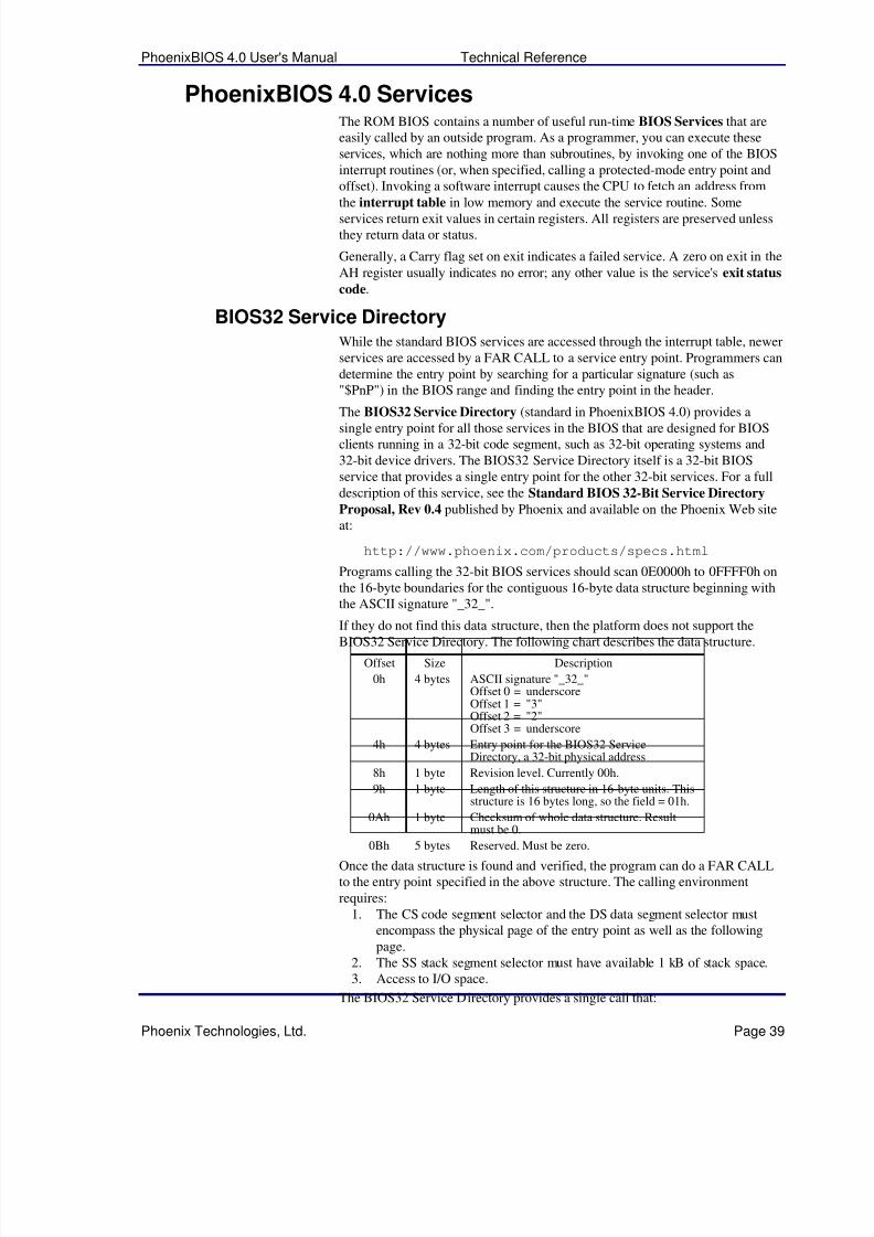
5/14/2018 PhoenixBIOS4_rev6UserMan - slidepdf.com
http://slidepdf.com/reader/full/phoenixbios4rev6userman 43/88
PhoenixBIOS 4.0 User's Manual Technical Reference
Phoenix Technologies, Ltd. Page 39
PhoenixBIOS 4.0 ServicesThe ROM BIOS contains a number of useful run-time BIOS Services that areeasily called by an outside program. As a programmer, you can execute theseservices, which are nothing more than subroutines, by invoking one of the BIOSinterrupt routines (or, when specified, calling a protected-mode entry point andoffset). Invoking a software interrupt causes the CPU to fetch an address from
the interrupt table in low memory and execute the service routine. Someservices return exit values in certain registers. All registers are preserved unlessthey return data or status.
Generally, a Carry flag set on exit indicates a failed service. A zero on exit in the
AH register usually indicates no error; any other value is the service's exit status
code.
BIOS32 Service DirectoryWhile the standard BIOS services are accessed through the interrupt table, newerservices are accessed by a FAR CALL to a service entry point. Programmers candetermine the entry point by searching for a particular signature (such as"$PnP") in the BIOS range and finding the entry point in the header.
The BIOS32 Service Directory (standard in PhoenixBIOS 4.0) provides asingle entry point for all those services in the BIOS that are designed for BIOSclients running in a 32-bit code segment, such as 32-bit operating systems and32-bit device drivers. The BIOS32 Service Directory itself is a 32-bit BIOSservice that provides a single entry point for the other 32-bit services. For a fulldescription of this service, see the Standard BIOS 32-Bit Service Directory
Proposal, Rev 0.4 published by Phoenix and available on the Phoenix Web siteat:
http://www.phoenix.com/products/specs.html
Programs calling the 32-bit BIOS services should scan 0E0000h to 0FFFF0h onthe 16-byte boundaries for the contiguous 16-byte data structure beginning withthe ASCII signature "_32_".
If they do not find this data structure, then the platform does not support theBIOS32 Service Directory. The following chart describes the data structure.
Offset Size Description
0h 4 bytes ASCII signature "_32_"Offset 0 = underscoreOffset 1 = "3"Offset 2 = "2"Offset 3 = underscore
4h 4 bytes Entry point for the BIOS32 ServiceDirectory, a 32-bit physical address
8h 1 byte Revision level. Currently 00h.
9h 1 byte Length of this structure in 16-byte units. Thisstructure is 16 bytes long, so the field = 01h.
0Ah 1 byte Checksum of whole data structure. Resultmust be 0.
0Bh 5 bytes Reserved. Must be zero.
Once the data structure is found and verified, the program can do a FAR CALLto the entry point specified in the above structure. The calling environmentrequires:
1. The CS code segment selector and the DS data segment selector mustencompass the physical page of the entry point as well as the followingpage.
2. The SS stack segment selector must have available 1 kB of stack space.3. Access to I/O space.
The BIOS32 Service Directory provides a single call that:
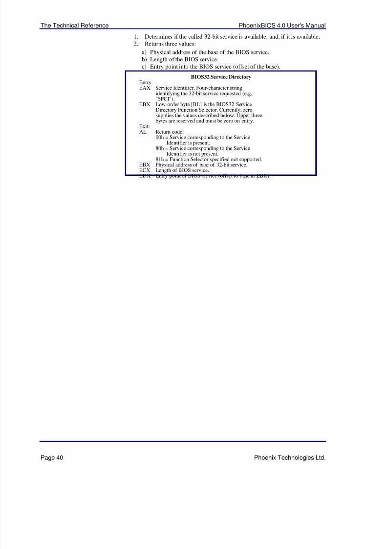
5/14/2018 PhoenixBIOS4_rev6UserMan - slidepdf.com
http://slidepdf.com/reader/full/phoenixbios4rev6userman 44/88
The Technical Reference PhoenixBIOS 4.0 User's Manual
Page 40 Phoenix Technologies Ltd.
1. Determines if the called 32-bit service is available, and, if it is available,2. Returns three values:
a) Physical address of the base of the BIOS service.b) Length of the BIOS service.c) Entry point into the BIOS service (offset of the base).
BIOS32 Service DirectoryEntry:EAX Service Identifier. Four-character string
identifying the 32-bit service requested (e.g.,"$PCI").
EBX Low-order byte [BL] is the BIOS32 ServiceDirectory Function Selector. Currently, zerosupplies the values described below. Upper threebytes are reserved and must be zero on entry.
Exit:AL Return code:
00h = Service corresponding to the ServiceIdentifier is present.
80h = Service corresponding to the ServiceIdentifier is not present.
81h = Function Selector specified not supported.EBX Physical address of base of 32-bit service.ECX Length of BIOS service.EDX Entry point of BIOS service (offset to base in EBX).
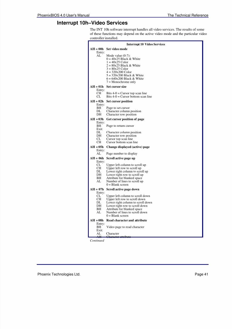
5/14/2018 PhoenixBIOS4_rev6UserMan - slidepdf.com
http://slidepdf.com/reader/full/phoenixbios4rev6userman 45/88
PhoenixBIOS 4.0 User's Manual The Technical Reference
Phoenix Technologies Ltd. Page 41
Interrupt 10h–Video ServicesThe INT 10h software interrupt handles all video services. The results of someof these functions may depend on the active video mode and the particular videocontroller installed.
Interrupt 10 Video Services
AH = 00h Set video modeEntry:
AL Mode value (0-7):0 = 40x25 Black & White1 = 40x25 Color2 = 80x25 Black & White3 = 80x25 Color4 = 320x200 Color5 = 320x200 Black & White6 = 640x200 Black & White7 = Monochrome only
AH = 01h Set cursor sizeEntry:CH Bits 4-0 = Cursor top scan lineCL Bits 4-0 = Cursor bottom scan line
AH = 02h Set cursor positionEntry:BH Page to set cursor
DL Character column positionDH Character row position
AH = 03h Get cursor position of pageEntry:BH Page to return cursorExit:DL Character column positionDH Character row positionCL Cursor top scan lineCH Cursor bottom scan line
AH = 05h Change displayed (active) pageEntry:AL Page number to display
AH = 06h Scroll active page upEntry:CL Upper left column to scroll upCH Upper left row to scroll upDL Lower right column to scroll upDH Lower right row to scroll upBH Attribute for blanked spaceAL Number of lines to scroll up
0 = Blank screen
AH = 07h Scroll active page downEntry:CL Upper left column to scroll downCH Upper left row to scroll downDL Lower right column to scroll downDH Lower right row to scroll downBH Attribute for blanked spaceAL Number of lines to scroll down
0 = Blank screen
AH = 08h Read character and attributeEntry:BH Video page to read characterExit:AL CharacterAH Character attribute
Continued
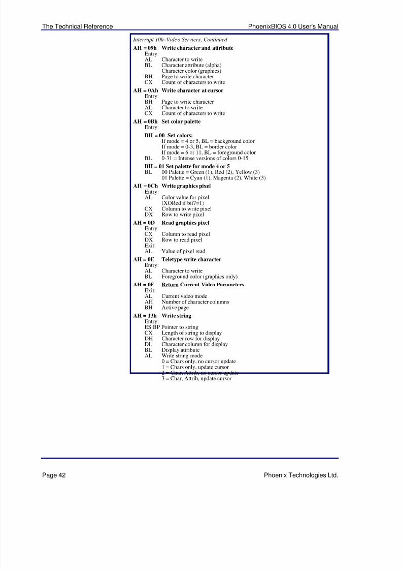
5/14/2018 PhoenixBIOS4_rev6UserMan - slidepdf.com
http://slidepdf.com/reader/full/phoenixbios4rev6userman 46/88
The Technical Reference PhoenixBIOS 4.0 User's Manual
Page 42 Phoenix Technologies Ltd.
Interrupt 10h–Video Services, Continued
AH = 09h Write character and attributeEntry:AL Character to writeBL Character attribute (alpha)
Character color (graphics)BH Page to write characterCX Count of characters to write
AH = 0Ah Write character at cursor
Entry:BH Page to write characterAL Character to writeCX Count of characters to write
AH = 0Bh Set color paletteEntry:
BH = 00 Set colors:If mode = 4 or 5, BL = background colorIf mode = 0-3, BL = border colorIf mode = 6 or 11, BL = foreground color
BL 0-31 = Intense versions of colors 0-15
BH = 01 Set palette for mode 4 or 5BL 00 Palette = Green (1), Red (2), Yellow (3)
01 Palette = Cyan (1), Magenta (2), White (3)
AH = 0Ch Write graphics pixel
Entry:AL Color value for pixel(XORed if bit7=1)
CX Column to write pixelDX Row to write pixel
AH = 0D Read graphics pixelEntry:CX Column to read pixelDX Row to read pixelExit:AL Value of pixel read
AH = 0E Teletype write characterEntry:AL Character to writeBL Foreground color (graphics only)
AH = 0F Return Current Video Parameters
Exit:AL Current video modeAH Number of character columnsBH Active page
AH = 13h Write stringEntry:ES:BP Pointer to stringCX Length of string to displayDH Character row for displayDL Character column for displayBL Display attributeAL Write string mode
0 = Chars only, no cursor update1 = Chars only, update cursor2 = Char, Attrib, no cursor update3 = Char, Attrib, update cursor
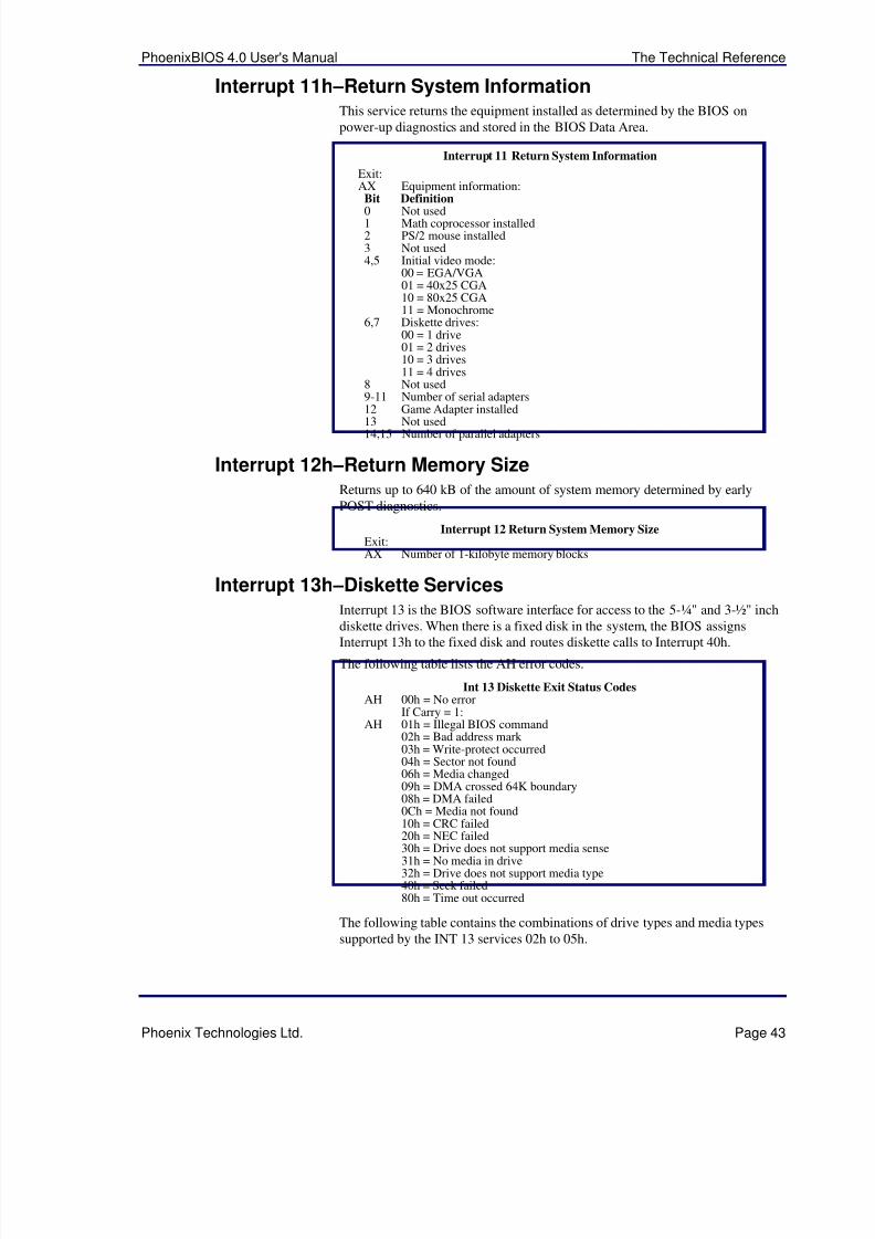
5/14/2018 PhoenixBIOS4_rev6UserMan - slidepdf.com
http://slidepdf.com/reader/full/phoenixbios4rev6userman 47/88
PhoenixBIOS 4.0 User's Manual The Technical Reference
Phoenix Technologies Ltd. Page 43
Interrupt 11h –Return System InformationThis service returns the equipment installed as determined by the BIOS onpower-up diagnostics and stored in the BIOS Data Area.
Interrupt 11 Return System Information
Exit:AX Equipment information:Bit Definition
0 Not used1 Math coprocessor installed2 PS/2 mouse installed3 Not used4,5 Initial video mode:
00 = EGA/VGA01 = 40x25 CGA10 = 80x25 CGA11 = Monochrome
6,7 Diskette drives:00 = 1 drive01 = 2 drives10 = 3 drives11 = 4 drives
8 Not used9-11 Number of serial adapters12 Game Adapter installed
13 Not used14,15 Number of parallel adapters
Interrupt 12h –Return Memory SizeReturns up to 640 kB of the amount of system memory determined by earlyPOST diagnostics.
Interrupt 12 Return System Memory SizeExit:AX Number of 1-kilobyte memory blocks
Interrupt 13h –Diskette ServicesInterrupt 13 is the BIOS software interface for access to the 5-¼" and 3-½" inch
diskette drives. When there is a fixed disk in the system, the BIOS assignsInterrupt 13h to the fixed disk and routes diskette calls to Interrupt 40h.
The following table lists the AH error codes.
Int 13 Diskette Exit Status CodesAH 00h = No error
If Carry = 1:AH 01h = Illegal BIOS command
02h = Bad address mark 03h = Write-protect occurred04h = Sector not found06h = Media changed09h = DMA crossed 64K boundary08h = DMA failed0Ch = Media not found10h = CRC failed
20h = NEC failed30h = Drive does not support media sense31h = No media in drive32h = Drive does not support media type40h = Seek failed80h = Time out occurred
The following table contains the combinations of drive types and media typessupported by the INT 13 services 02h to 05h.

5/14/2018 PhoenixBIOS4_rev6UserMan - slidepdf.com
http://slidepdf.com/reader/full/phoenixbios4rev6userman 48/88
The Technical Reference PhoenixBIOS 4.0 User's Manual
Page 44 Phoenix Technologies Ltd.
Diskette TypesMedia Drive Sec/Trk Tracks360 kB 360 kB 8-9 40360 kB 1.2 MB 8-9 401.2 MB 1.2 MB 15 80720 kB 720 kB 9 80720 kB 1.44 MB 9 801.44 MB 1.44 MB 18 80720 kB 2.88 MB 9 801.44 MB 2.88 MB 18 90
2.88 MB 2.88 MB 36 80
The following describes the diskette services with their entry and exit values.
Interrupt 13h Diskette Services
AH = 00h Reset diskette system
AH = 01h Return diskette statusExit:AH 00h = No error
01h = Illegal BIOS command02h = Address mark not found03h = Write-protect error04h = Sector not found06h = Media has been changed08h = DMA overrun09h = DMA boundary error
0Ch = Media not found10h = CRC error20h = NEC error40h = Seek error80h = Time out occurred
AH = 02h Read diskette sectorsEntry:ES:BX Buffer addressDL Drive number (0-1)DH Head number (0-1)CH Track number (0-79)CL Sector number (8-36)AL Number of sectors (1-15)Exit:AL Number of sectors transferred
AH = 03h Write diskette sectors
Entry:ES:BX Buffer addressDL Drive number (0-1)DH Head number (0-1)CH Track number (0-79)CL Sector number (8-36)AL Number of sectors (1-15)Exit:AL Number of sectors transferred
AH = 04h Verify diskette sectorsEntry:DL Drive number (0-1)DH Head number (0-1)CH Track number (0-79)CL Sector number (8-36)AL Number of sectors (1-15)
Exit:AL Number of sectors verifiedContinued

5/14/2018 PhoenixBIOS4_rev6UserMan - slidepdf.com
http://slidepdf.com/reader/full/phoenixbios4rev6userman 49/88
PhoenixBIOS 4.0 User's Manual The Technical Reference
Phoenix Technologies Ltd. Page 45
Interrupt 13h–Diskette Services, Continued
AH = 05h Format diskette trackEntry:ES:BX Buffer addressDL Drive number (0-1)DH Head number (0-1)CH Track number (0-79)AL Number of sectors (1-15)Exit:
AL Number of sectors formattedAH = 08h Read drive parameters
Entry:DL Drive numberExit:ES:DI Pointer to parameter tableDH Maximum head numberDL Number of diskette drives presentCH Maximum track numberCL Drive capacity:
Bits 0-5 Maximum sector numberBits 6-7 Maximum track number
BL Diskette drive type from CMOS:Bits 0-3:00 = CMOS not present or invalid01 = 360 kB02 = 1.2 MB
03 = 720 kB04 = 1.44 MB06 = 2.88 MB
Bits 4-7: 0
AH = 15h Read drive typeEntry:DL Drive numberExit:AH 00 = Drive not present
01 = Drive cannot detect media change02 = Drive can detect media change03 = Fixed disk
AH = 16h Detect media changeEntry:DL Drive Number (0-1)Exit:
If Carry = 0:AH 00 = Disk change not active
01 = Invalid drive number06 = Either disk change line active or
change line not supported80h = Drive not ready or no drive present:
(timeout)
AH = 17h Set diskette typeEntry:AL Format:
00 = Invalid Request01 = 360kB floppy in 360kB drive02 = 360kB floppy in 1.2MB drive03 = 1.2MB floppy in 1.2MB drive04 = 720kB floppy in 720kB (1.44MB not supported)
DL Drive Number (0-1)
AH = 18h Set media type for formatEntry:CH Maximum track numberCL Diskette parameters:
Bits 0-5: Maximum sector numberBits 6-7: Maximum track number
DL Drive Number (0-1)Exit:ES:DI Pointer to parameter table
Continued
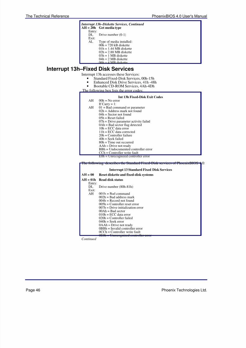
5/14/2018 PhoenixBIOS4_rev6UserMan - slidepdf.com
http://slidepdf.com/reader/full/phoenixbios4rev6userman 50/88
The Technical Reference PhoenixBIOS 4.0 User's Manual
Page 46 Phoenix Technologies Ltd.
Interrupt 13h – Diskette Services, Continued AH = 20h Get media type
Entry:DL Drive number (0-1)Exit:AL Type of media installed:
00h = 720 kB diskette01h = 1.44 MB diskette02h = 2.88 MB diskette03h = 1 MB diskette
04h = 2 MB diskette06h = 4 MB diskette
Interrupt 13h –Fixed Disk ServicesInterrupt 13h accesses these Services:
• Standard Fixed-Disk Services, 00h-15h• Enhanced Disk Drive Services, 41h -48h• Bootable CD-ROM Services, 4Ah-4Dh
The following box lists the error codes:
Int 13h Fixed-Disk Exit CodesAH 00h = No error
If Carry = 1:AH 01 = Bad command or parameter
02h = Address mark not found04h = Sector not found
05h = Reset failed07h = Drive parameter activity failed0Ah = Bad sector flag detected10h = ECC data error11h = ECC data corrected20h = Controller failure40h = Seek failed80h = Time out occurredAAh = Drive not readyBBh = Undocumented controller errorCCh = Controller write faultE0h = Unrecognized controller error
The following describes the Standard Fixed-Disk services of PhoenixBIOS 4.0:
Interrupt 13 Standard Fixed Disk Services
AH = 00 Reset diskette and fixed-disk systems
AH = 01h Read disk statusEntry:DL Drive number (80h-81h)Exit:AH 001h = Bad command
002h = Bad address mark 004h = Record not found005h = Controller reset error007h = Drive initialization error00Ah = Bad sector010h = ECC data error020h = Controller failed040h = Seek error0AAh = Drive not ready0BBh = Invalid controller error0CCh = Controller write fault
0E0h = Unrecognized controller errorContinued
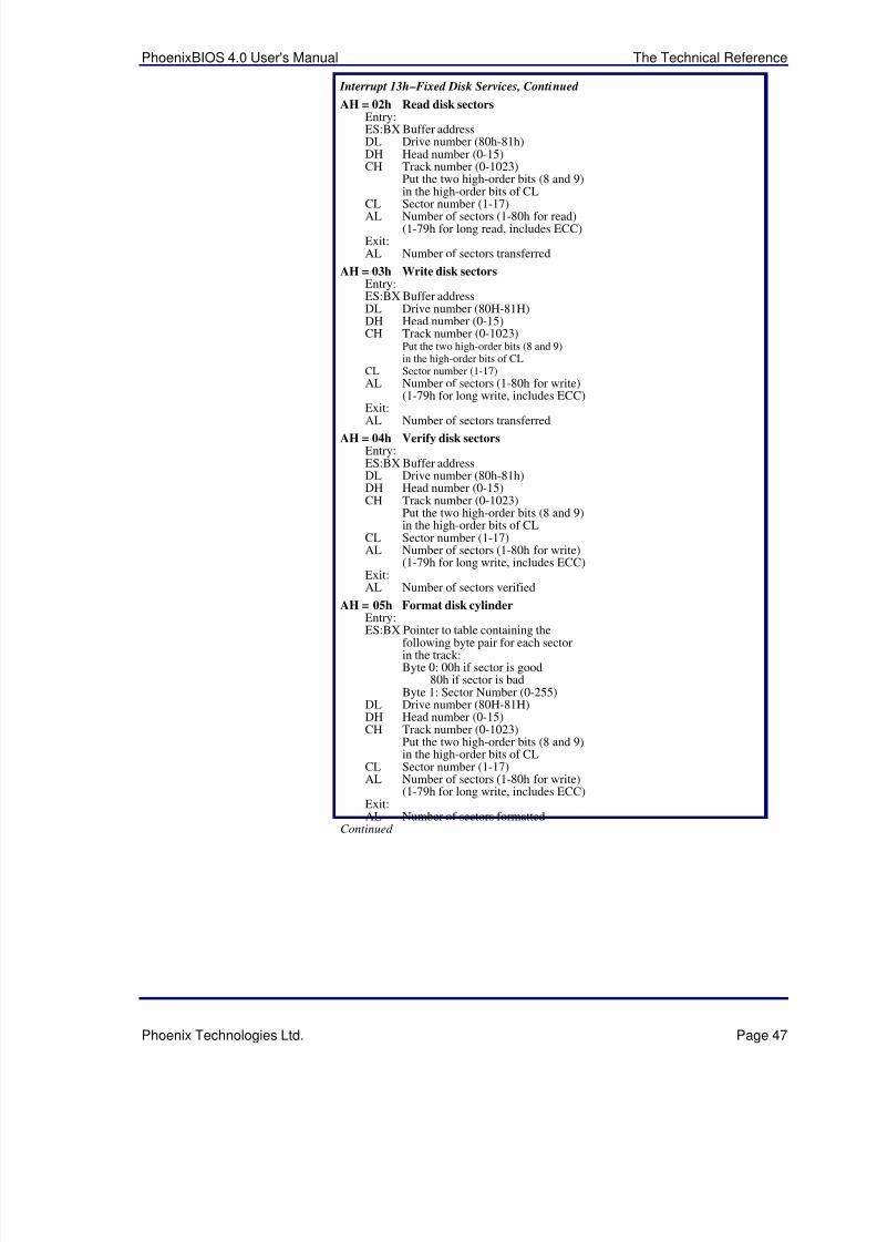
5/14/2018 PhoenixBIOS4_rev6UserMan - slidepdf.com
http://slidepdf.com/reader/full/phoenixbios4rev6userman 51/88
PhoenixBIOS 4.0 User's Manual The Technical Reference
Phoenix Technologies Ltd. Page 47
Interrupt 13h – Fixed Disk Services, Continued
AH = 02h Read disk sectorsEntry:ES:BX Buffer addressDL Drive number (80h-81h)DH Head number (0-15)CH Track number (0-1023)
Put the two high-order bits (8 and 9)in the high-order bits of CL
CL Sector number (1-17)AL Number of sectors (1-80h for read)(1-79h for long read, includes ECC)
Exit:AL Number of sectors transferred
AH = 03h Write disk sectorsEntry:ES:BX Buffer addressDL Drive number (80H-81H)DH Head number (0-15)CH Track number (0-1023)
Put the two high-order bits (8 and 9)in the high-order bits of CL
CL Sector number (1-17)AL Number of sectors (1-80h for write)
(1-79h for long write, includes ECC)Exit:
AL Number of sectors transferredAH = 04h Verify disk sectors
Entry:ES:BX Buffer addressDL Drive number (80h-81h)DH Head number (0-15)CH Track number (0-1023)
Put the two high-order bits (8 and 9)in the high-order bits of CL
CL Sector number (1-17)AL Number of sectors (1-80h for write)
(1-79h for long write, includes ECC)Exit:AL Number of sectors verified
AH = 05h Format disk cylinderEntry:
ES:BX Pointer to table containing thefollowing byte pair for each sectorin the track:Byte 0: 00h if sector is good
80h if sector is badByte 1: Sector Number (0-255)
DL Drive number (80H-81H)DH Head number (0-15)CH Track number (0-1023)
Put the two high-order bits (8 and 9)in the high-order bits of CL
CL Sector number (1-17)AL Number of sectors (1-80h for write)
(1-79h for long write, includes ECC)Exit:AL Number of sectors formatted
Continued
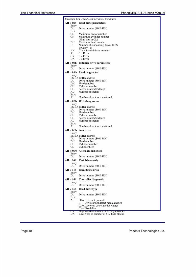
5/14/2018 PhoenixBIOS4_rev6UserMan - slidepdf.com
http://slidepdf.com/reader/full/phoenixbios4rev6userman 52/88
The Technical Reference PhoenixBIOS 4.0 User's Manual
Page 48 Phoenix Technologies Ltd.
Interrupt 13h –Fixed Disk Services, Continued
AH = 08h Read drive parametersEntry:DL Drive number (80H-81H)Exit:CL Maximum sector numberCH Maximum cylinder number
(High bits in CL)DH Maximum head numberDL Number of responding drives (0-2)
If Carry - 1:AH 07h = Invalid drive numberAL 0 = ErrorCX 0 = ErrorDX 0 = Error
AH = 09h Initialize drive parametersEntry:DL Drive number (80H-81H)
AH = 0Ah Read long sectorEntry:ES:BX Buffer addressDL Drive number (80H-81H)DH Head numberCH Cylinder numberCL Sector number/Cyl highAL Number of sectorsExit:AL Number of sectors transferred
AH = 0Bh Write long sectorEntry:ES:BX Buffer addressDL Drive number (80H-81H)DH Head numberCH Cylinder numberCL Sector number/Cyl highAL Number of sectorsExit:AL Number of sectors transferred
AH = 0Ch Seek driveEntry:ES:BX Buffer addressDL Drive number (80H-81H)DH Head numberCH Cylinder numberCL Cylinder high
AH = 0Dh Alternate disk resetEntry:DL Drive number (80H-81H)
AH = 10h Test drive readyEntry:DL Drive number (80H-81H)
AH = 11h Recalibrate driveEntry:DL Drive number (80H-81H)
AH = 14h Controller diagnosticEntry:DL Drive number (80H-81H)
AH = 15h Read drive typeEntry:DL Drive number (80H-81H)Exit:AH 00 = Drive not present
01 = Drive cannot detect media change02 = Drive can detect media change03 = Fixed disk
CX High word of number of 512-byte blocksDX Low word of number of 512-byte blocks
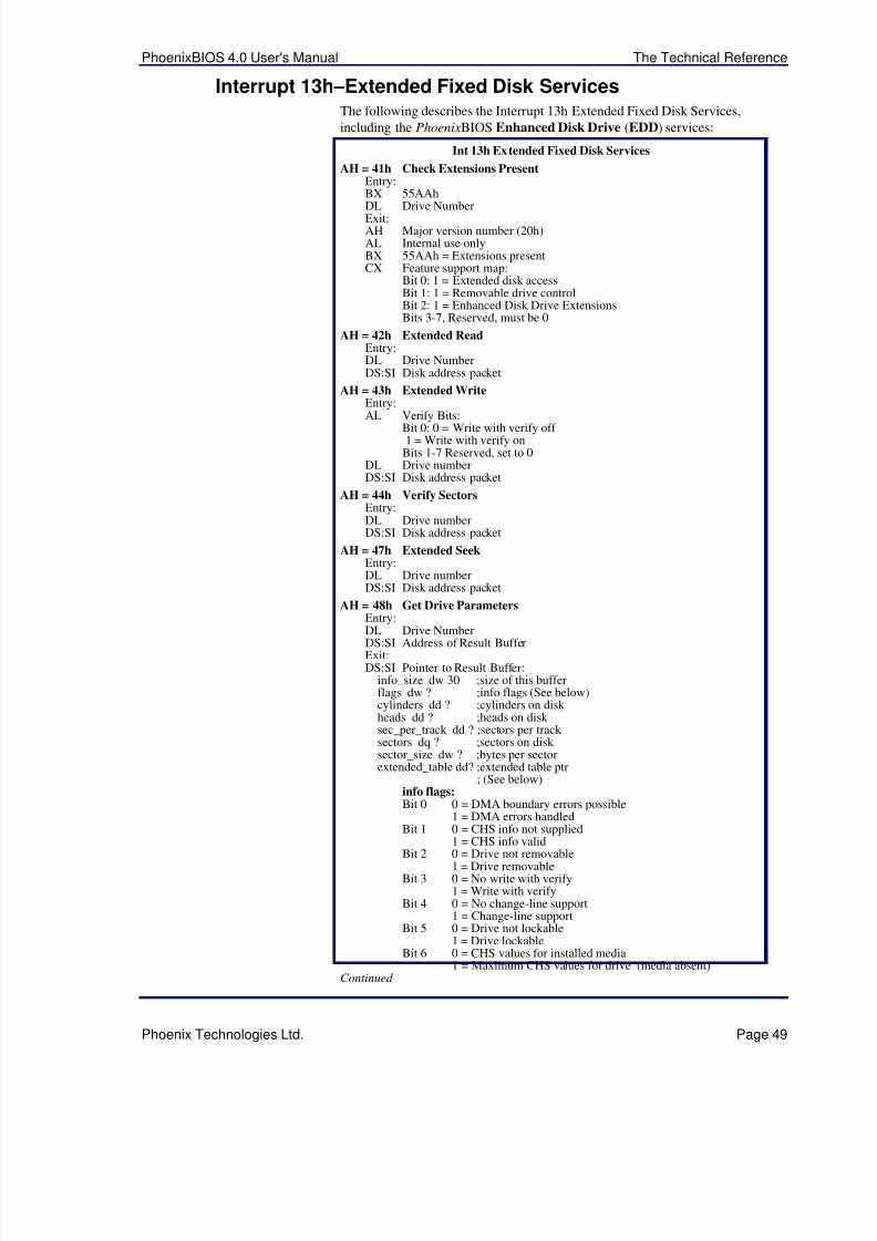
5/14/2018 PhoenixBIOS4_rev6UserMan - slidepdf.com
http://slidepdf.com/reader/full/phoenixbios4rev6userman 53/88
PhoenixBIOS 4.0 User's Manual The Technical Reference
Phoenix Technologies Ltd. Page 49
Interrupt 13h –Extended Fixed Disk ServicesThe following describes the Interrupt 13h Extended Fixed Disk Services,
including the PhoenixBIOS Enhanced Disk Drive (EDD) services:
Int 13h Extended Fixed Disk Services
AH = 41h Check Extensions PresentEntry:BX 55AAh
DL Drive NumberExit:AH Major version number (20h)AL Internal use onlyBX 55AAh = Extensions presentCX Feature support map:
Bit 0: 1 = Extended disk accessBit 1: 1 = Removable drive controlBit 2: 1 = Enhanced Disk Drive ExtensionsBits 3-7, Reserved, must be 0
AH = 42h Extended ReadEntry:DL Drive NumberDS:SI Disk address packet
AH = 43h Extended WriteEntry:
AL Verify Bits:Bit 0: 0 = Write with verify off 1 = Write with verify on
Bits 1-7 Reserved, set to 0DL Drive numberDS:SI Disk address packet
AH = 44h Verify SectorsEntry:DL Drive numberDS:SI Disk address packet
AH = 47h Extended SeekEntry:DL Drive numberDS:SI Disk address packet
AH = 48h Get Drive ParametersEntry:
DL Drive NumberDS:SI Address of Result BufferExit:DS:SI Pointer to Result Buffer:
info_size dw 30 ;size of this bufferflags dw ? ;info flags (See below)cylinders dd ? ;cylinders on disk heads dd ? ;heads on disk sec_per_track dd ? ;sectors per track sectors dq ? ;sectors on disk sector_size dw ? ;bytes per sectorextended_table dd? ;extended table ptr
; (See below)info flags: Bit 0 0 = DMA boundary errors possible
1 = DMA errors handledBit 1 0 = CHS info not supplied
1 = CHS info validBit 2 0 = Drive not removable
1 = Drive removableBit 3 0 = No write with verify
1 = Write with verifyBit 4 0 = No change-line support
1 = Change-line supportBit 5 0 = Drive not lockable
1 = Drive lockableBit 6 0 = CHS values for installed media
1 = Maximum CHS values for drive (media absent)Continued
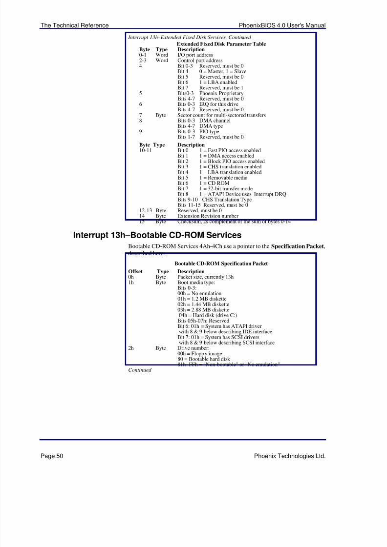
5/14/2018 PhoenixBIOS4_rev6UserMan - slidepdf.com
http://slidepdf.com/reader/full/phoenixbios4rev6userman 54/88
The Technical Reference PhoenixBIOS 4.0 User's Manual
Page 50 Phoenix Technologies Ltd.
Interrupt 13h – Extended Fixed Disk Services, Continued
Extended Fixed Disk Parameter TableByte Type Description0-1 Word I/O port address2-3 Word Control port address4 Bit 0-3 Reserved, must be 0
Bit 4 0 = Master, 1 = SlaveBit 5 Reserved, must be 0Bit 6 1 = LBA enabledBit 7 Reserved, must be 1
5 Bits0-3 Phoenix ProprietaryBits 4-7 Reserved, must be 0
6 Bits 0-3 IRQ for this driveBits 4-7 Reserved, must be 0
7 Byte Sector count for multi-sectored transfers8 Bits 0-3 DMA channel
Bits 4-7 DMA type9 Bits 0-3 PIO type
Bits 1-7 Reserved, must be 0
Byte Type Description10-11 Bit 0 1 = Fast PIO access enabled
Bit 1 1 = DMA access enabledBit 2 1 = Block PIO access enabledBit 3 1 = CHS translation enabledBit 4 1 = LBA translation enabledBit 5 1 = Removable media
Bit 6 1 = CD ROMBit 7 1 = 32-bit transfer modeBit 8 1 = ATAPI Device uses Interrupt DRQBits 9-10 CHS Translation TypeBits 11-15 Reserved, must be 0
12-13 Byte Reserved, must be 014 Byte Extension Revision number15 Byte Checksum, 2s complement of the sum of bytes 0-14
Interrupt 13h –Bootable CD-ROM ServicesBootable CD-ROM Services 4Ah-4Ch use a pointer to the Specification Packet,described here:
Bootable CD-ROM Specification Packet
Offset Type Description
0h Byte Packet size, currently 13h1h Byte Boot media type:Bits 0-3:00h = No emulation01h = 1.2 MB diskette02h = 1.44 MB diskette03h = 2.88 MB diskette04h = Hard disk (drive C:)
Bits 05h-07h: ReservedBit 6: 01h = System has ATAPI driverwith 8 & 9 below describing IDE interface.
Bit 7: 01h = System has SCSI driverswith 8 & 9 below describing SCSI interface
2h Byte Drive number:00h = Floppy image80 = Bootable hard disk 81h -FFh = "Non-bootable" or "No emulation"
Continued
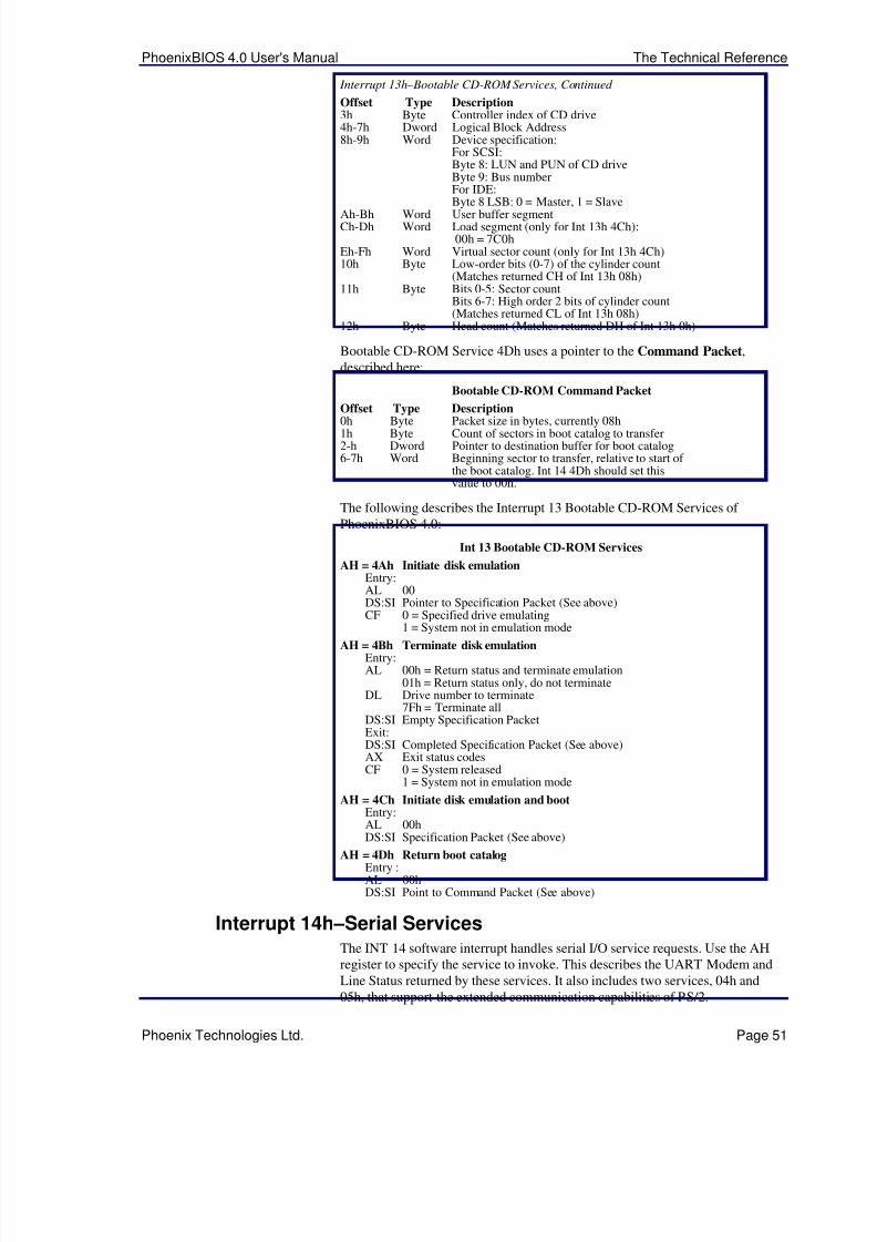
5/14/2018 PhoenixBIOS4_rev6UserMan - slidepdf.com
http://slidepdf.com/reader/full/phoenixbios4rev6userman 55/88
PhoenixBIOS 4.0 User's Manual The Technical Reference
Phoenix Technologies Ltd. Page 51
Interrupt 13h – Bootable CD-ROM Services, Continued
Offset Type Description3h Byte Controller index of CD drive4h-7h Dword Logical Block Address8h-9h Word Device specification:
For SCSI:Byte 8: LUN and PUN of CD driveByte 9: Bus numberFor IDE:Byte 8 LSB: 0 = Master, 1 = Slave
Ah-Bh Word User buffer segmentCh-Dh Word Load segment (only for Int 13h 4Ch):
00h = 7C0hEh-Fh Word Virtual sector count (only for Int 13h 4Ch)10h Byte Low-order bits (0-7) of the cylinder count
(Matches returned CH of Int 13h 08h)11h Byte Bits 0-5: Sector count
Bits 6-7: High order 2 bits of cylinder count(Matches returned CL of Int 13h 08h)
12h Byte Head count (Matches returned DH of Int 13h 0h)
Bootable CD-ROM Service 4Dh uses a pointer to the Command Packet,described here:
Bootable CD-ROM Command Packet
Offset Type Description
0h Byte Packet size in bytes, currently 08h1h Byte Count of sectors in boot catalog to transfer2-h Dword Pointer to destination buffer for boot catalog6-7h Word Beginning sector to transfer, relative to start of
the boot catalog. Int 14 4Dh should set thisvalue to 00h.
The following describes the Interrupt 13 Bootable CD-ROM Services of PhoenixBIOS 4.0:
Int 13 Bootable CD-ROM Services
AH = 4Ah Initiate disk emulationEntry:AL 00DS:SI Pointer to Specification Packet (See above)CF 0 = Specified drive emulating
1 = System not in emulation modeAH = 4Bh Terminate disk emulation
Entry:AL 00h = Return status and terminate emulation
01h = Return status only, do not terminateDL Drive number to terminate
7Fh = Terminate allDS:SI Empty Specification PacketExit:DS:SI Completed Specification Packet (See above)AX Exit status codesCF 0 = System released
1 = System not in emulation mode
AH = 4Ch Initiate disk emulation and bootEntry:AL 00h
DS:SI Specification Packet (See above)AH = 4Dh Return boot catalog
Entry :AL 00hDS:SI Point to Command Packet (See above)
Interrupt 14h –Serial ServicesThe INT 14 software interrupt handles serial I/O service requests. Use the AHregister to specify the service to invoke. This describes the UART Modem andLine Status returned by these services. It also includes two services, 04h and05h, that support the extended communication capabilities of PS/2.
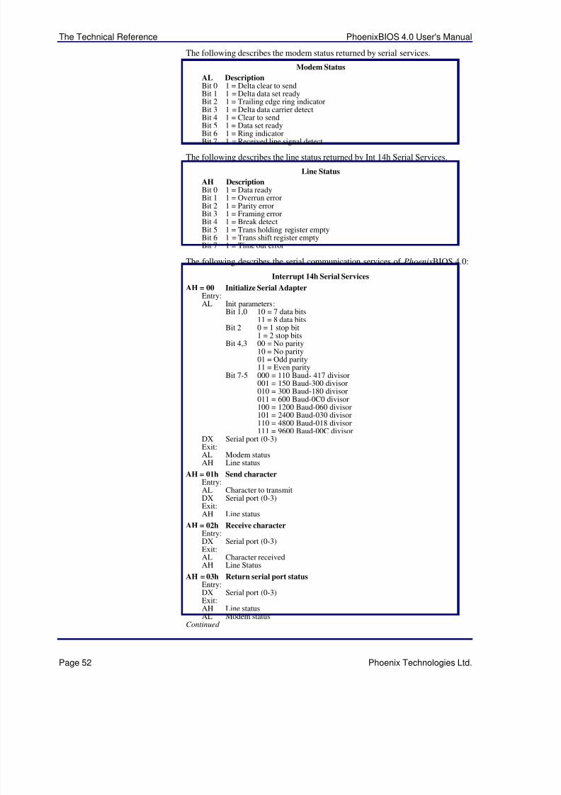
5/14/2018 PhoenixBIOS4_rev6UserMan - slidepdf.com
http://slidepdf.com/reader/full/phoenixbios4rev6userman 56/88
The Technical Reference PhoenixBIOS 4.0 User's Manual
Page 52 Phoenix Technologies Ltd.
The following describes the modem status returned by serial services.
Modem Status
AL DescriptionBit 0 1 = Delta clear to sendBit 1 1 = Delta data set readyBit 2 1 = Trailing edge ring indicatorBit 3 1 = Delta data carrier detectBit 4 1 = Clear to sendBit 5 1 = Data set ready
Bit 6 1 = Ring indicatorBit 7 1 = Received line signal detect
The following describes the line status returned by Int 14h Serial Services.
Line Status
AH DescriptionBit 0 1 = Data readyBit 1 1 = Overrun errorBit 2 1 = Parity errorBit 3 1 = Framing errorBit 4 1 = Break detectBit 5 1 = Trans holding register emptyBit 6 1 = Trans shift register emptyBit 7 1 = Time out error
The following describes the serial communication services of PhoenixBIOS 4.0:
Interrupt 14h Serial Services
AH = 00 Initialize Serial AdapterEntry:AL Init parameters:
Bit 1,0 10 = 7 data bits11 = 8 data bits
Bit 2 0 = 1 stop bit1 = 2 stop bits
Bit 4,3 00 = No parity10 = No parity01 = Odd parity11 = Even parity
Bit 7-5 000 = 110 Baud- 417 divisor001 = 150 Baud-300 divisor010 = 300 Baud-180 divisor011 = 600 Baud-0C0 divisor100 = 1200 Baud-060 divisor101 = 2400 Baud-030 divisor110 = 4800 Baud-018 divisor111 = 9600 Baud-00C divisor
DX Serial port (0-3)Exit:AL Modem statusAH Line status
AH = 01h Send characterEntry:AL Character to transmitDX Serial port (0-3)Exit:AH Line status
AH = 02h Receive characterEntry:DX Serial port (0-3)Exit:AL Character receivedAH Line Status
AH = 03h Return serial port statusEntry:DX Serial port (0-3)Exit:AH Line statusAL Modem status
Continued
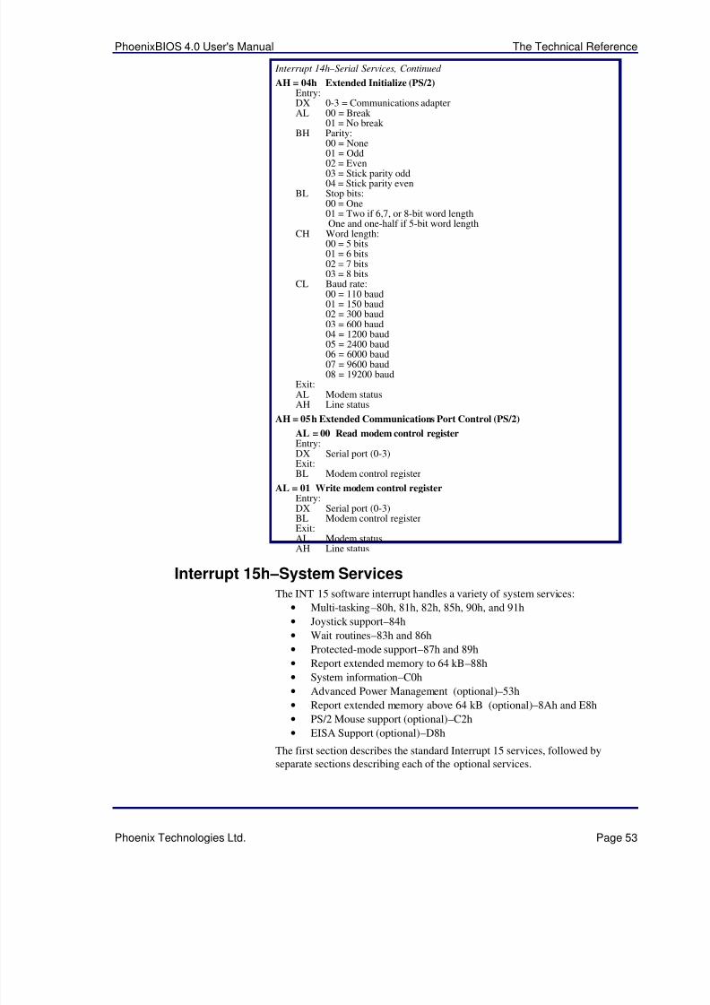
5/14/2018 PhoenixBIOS4_rev6UserMan - slidepdf.com
http://slidepdf.com/reader/full/phoenixbios4rev6userman 57/88
PhoenixBIOS 4.0 User's Manual The Technical Reference
Phoenix Technologies Ltd. Page 53
Interrupt 14h –Serial Services, Continued
AH = 04h Extended Initialize (PS/2)Entry:DX 0-3 = Communications adapterAL 00 = Break
01 = No break BH Parity:
00 = None01 = Odd02 = Even03 = Stick parity odd04 = Stick parity even
BL Stop bits:00 = One01 = Two if 6,7, or 8-bit word lengthOne and one-half if 5-bit word length
CH Word length:00 = 5 bits01 = 6 bits02 = 7 bits03 = 8 bits
CL Baud rate:00 = 110 baud01 = 150 baud02 = 300 baud03 = 600 baud04 = 1200 baud05 = 2400 baud06 = 6000 baud07 = 9600 baud08 = 19200 baud
Exit:AL Modem statusAH Line status
AH = 05h Extended Communications Port Control (PS/2)
AL = 00 Read modem control registerEntry:DX Serial port (0-3)Exit:BL Modem control register
AL = 01 Write modem control registerEntry:
DX Serial port (0-3)BL Modem control registerExit:AL Modem statusAH Line status
Interrupt 15h –System ServicesThe INT 15 software interrupt handles a variety of system services:
• Multi-tasking–80h, 81h, 82h, 85h, 90h, and 91h
• Joystick support–84h
• Wait routines–83h and 86h
• Protected-mode support–87h and 89h
• Report extended memory to 64 kB–88h
• System information–C0h• Advanced Power Management (optional)–53h
• Report extended memory above 64 kB (optional)–8Ah and E8h
• PS/2 Mouse support (optional)–C2h
• EISA Support (optional)–D8h
The first section describes the standard Interrupt 15 services, followed byseparate sections describing each of the optional services.
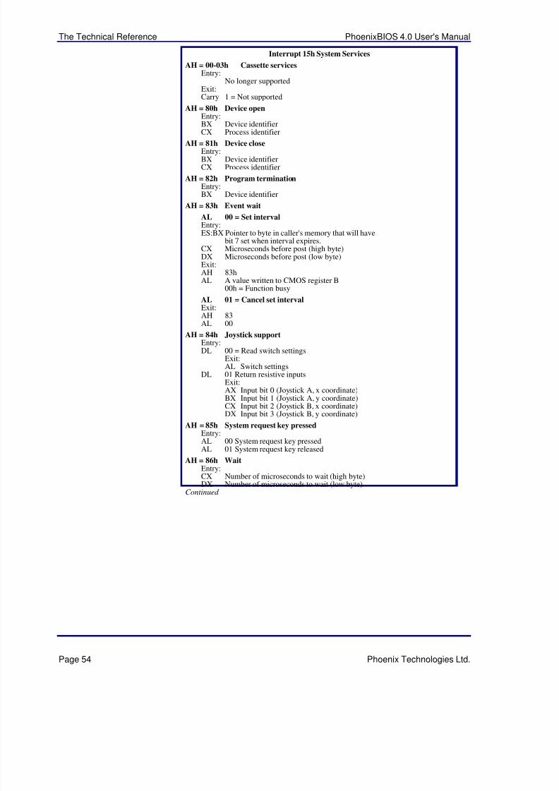
5/14/2018 PhoenixBIOS4_rev6UserMan - slidepdf.com
http://slidepdf.com/reader/full/phoenixbios4rev6userman 58/88
The Technical Reference PhoenixBIOS 4.0 User's Manual
Page 54 Phoenix Technologies Ltd.
Interrupt 15h System Services
AH = 00-03h Cassette servicesEntry:
No longer supportedExit:Carry 1 = Not supported
AH = 80h Device openEntry:BX Device identifier
CX Process identifierAH = 81h Device close
Entry:BX Device identifierCX Process identifier
AH = 82h Program terminationEntry:BX Device identifier
AH = 83h Event wait
AL 00 = Set intervalEntry:ES:BX Pointer to byte in caller's memory that will have
bit 7 set when interval expires.CX Microseconds before post (high byte)DX Microseconds before post (low byte)
Exit:AH 83hAL A value written to CMOS register B
00h = Function busy
AL 01 = Cancel set intervalExit:AH 83AL 00
AH = 84h Joystick supportEntry:DL 00 = Read switch settings
Exit:AL Switch settings
DL 01 Return resistive inputsExit:AX Input bit 0 (Joystick A, x coordinate)
BX Input bit 1 (Joystick A, y coordinate)CX Input bit 2 (Joystick B, x coordinate)DX Input bit 3 (Joystick B, y coordinate)
AH = 85h System request key pressedEntry:AL 00 System request key pressedAL 01 System request key released
AH = 86h WaitEntry:CX Number of microseconds to wait (high byte)DX Number of microseconds to wait (low byte)
Continued
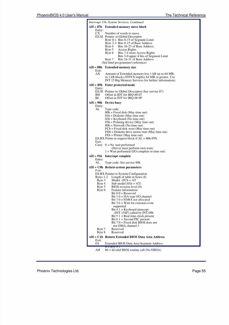
5/14/2018 PhoenixBIOS4_rev6UserMan - slidepdf.com
http://slidepdf.com/reader/full/phoenixbios4rev6userman 59/88
PhoenixBIOS 4.0 User's Manual The Technical Reference
Phoenix Technologies Ltd. Page 55
Interrupt 15h –System Services, Continued
AH = 87h Extended memory move blockEntry:CX Number of words to moveES:SI Pointer to Global Descriptor
Byte 0-1 Bits 0-15 of Segment LimitByte 2-3 Bits 0-15 of Base AddressByte 4 Bits 16-23 of Base AddressByte 5 Access RightsByte 6 Bits 7-4 more Access Rights
Bits 3-0 upper 4 bits of Segment LimitByte 7 Bits 24-31 of Base Address
(See Intel programmer's reference)
AH = 88h Extended memory size Exit:AX Amount of Extended memory less 1 kB up to 64 MB,
in 1 kB blocks (FFFCh implies 64 MB or greater. UseINT 15 Big Memory Services for further information).
AH = 89h Enter protected modeEntry:ES:SI Pointer to Global Descriptor (See service 87)BH Offset in IDT for IRQ 00-07BL Offset in IDT for IRQ 08-0F
AH = 90h Device busyEntry:
AL Type code:00h = Fixed disk (May time out)01h = Diskette (May time out)02h = Keyboard (No time out)03h = Pointing device (May time out)80h = Network (No time out)FCh = Fixed disk reset (May time out)FDh = Diskette drive motor start (May time out)FEh = Printer (May time out)
ES:BX Points to request block if AL = 80h-FFhExit:Carry 0 = No wait performed
(Driver must perform own wait)1 = Wait performed (I/O complete or time out)
AH = 91h Interrupt completeEntry:AL Type code: See service 90h
AH = C0h Return system parametersExit:ES:BX Pointer to System ConfigurationBytes 1-2 Length of table in bytes (8)Byte 3 Model (FCh = ATByte 4 Sub model (01h = AT)Byte 5 BIOS revision level (0)Byte 6 Feature information:
Bit 0 0 = ReservedBit 1 0 = ISA-type I/O channelBit 2 0 = EDBA not allocatedBit 3 0 = Wait for external event
supportedBit 4 1 = Keyboard intercept
(INT 154F) called by INT 09hBit 5 1 = Real time clock present
Bit 6 1 = Second PIC presentBit 7 0 = Fixed disk BIOS does notuse DMA channel 3
Byte 7 ReservedByte 8 Reserved
AH = C1h Return Extended BIOS Data Area AddressExit:ES Extended BIOS Data Area Segment Address
If Carry = 1AH 86 = Invalid BIOS routine call (No EBDA)
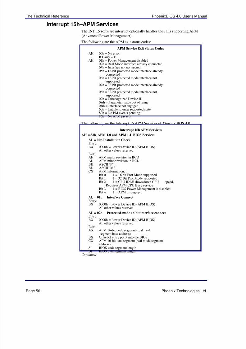
5/14/2018 PhoenixBIOS4_rev6UserMan - slidepdf.com
http://slidepdf.com/reader/full/phoenixbios4rev6userman 60/88
The Technical Reference PhoenixBIOS 4.0 User's Manual
Page 56 Phoenix Technologies Ltd.
Interrupt 15h –APM ServicesThe INT 15 software interrupt optionally handles the calls supporting APM(Advanced Power Management).
The following are the APM exit status codes:
APM Service Exit Status Codes
AH 00h = No errorIf Carry = 1:
AH 01h = Power Management disabled02h = Real Mode interface already connected03h = Interface not connected05h = 16-bit protected mode interface already
connected06h = 16-bit protected mode interface not
supported07h = 32-bit protected mode interface already
connected08h = 32-bit protected mode interface not
supported09h = Unrecognized Device ID0Ah = Parameter value out of range0Bh = Interface not engaged60h = Unable to enter requested state80h = No PM events pending
86h = No APM presentThe following are the Interrupt 15 APM Services of PhoenixBIOS 4.0:
Interrupt 15h APM Services
AH = 53h APM 1.0 and APM 1.1 BIOS Services
AL = 00h Installation CheckEntry:BX 0000h = Power Device ID (APM BIOS)
All other values reservedExit:AH APM major revision in BCDAL APM minor revision in BCDBH ASCII "P"BL ASCII "M"CX APM information:
Bit 0 1 = 16 bit Prot Mode supportedBit 1 1 = 32 Bit Prot Mode supportedBit 2 1 = CPU IDLE slows down CPU speed.
Requires APM CPU Busy serviceBit 3 1 = BIOS Power Management is disabledBit 4 1 = APM disengaged
AL = 01h Interface ConnectEntry:BX 0000h = Power Device ID (APM BIOS)
All other values reserved
AL = 02h Protected-mode 16-bit interface connectEntry:BX 0000h = Power Device ID (APM BIOS)
All other values reservedExit:AX APM 16-bit code segment (real mode
segment base address)BX Offset of entry point into the BIOSCX APM 16-bit data segment (real mode segment
address)SI BIOS code segment lengthDI BIOS data segment length
Continued

5/14/2018 PhoenixBIOS4_rev6UserMan - slidepdf.com
http://slidepdf.com/reader/full/phoenixbios4rev6userman 61/88
PhoenixBIOS 4.0 User's Manual The Technical Reference
Phoenix Technologies Ltd. Page 57
Interrupt 15h – APM Services, Continued
AL = 03h Protected-mode 32-bit interface connectEntry:BX Power Device ID, 0000h
All other values reservedExit:AX APM 32-bit code segment (real mode segment
base address)EBX Offset of entry point into the BIOSCX APM 16-bit data segment (real mode segment
address)DX APM data segment (real mode segment
address)SI BIOS code segment lengthDI BIOS data segment length
AL = 04h Protected-mode 32-bit interface connectEntry:BX 0000h = Power Device ID (APM BIOS)
All other values reserved
AL = 05h CPU Idle
AL = 06h CPU busy
AL = 07h Set Power StateEntry:BX Power Device ID:
0001h = All PM devices managed by the BIOS
01XXh = Display02XXh = Secondary Storage03XXh = Parallel Ports04XXh = Serial Ports05XXh = Network Adapters06XXh = PCMCIA SocketsE000h-EFFFh = OEM-defined power-deviceIDswhere:XXh = Unit Number (0 based)
Unit Number FFh = all units in this classCX Power State:
*0000h = APM enabled0001h = Standby0002h = Suspend0003h = Off **0004h = Last Request ProcessingNotification**0005h = Last Request Rejected0006h-001Fh = Reserved system states0020h-003Fh = OEM-defined system states0040h-007Fh = OEM-defined device states0080-FFFFh = Reserved device states* Not supported for Power Device ID 0001h**Only supported for Power Device ID 0001h
AL = 08h Enable/disable power managementEntry:BX Power Device ID:
0001h = All PM devices controlled by the BIOSFFFFh = All PM devices controlled by theBIOS (For compatibility with APM 1.0)All other values reserved
CX Function code:0000h = Disable power management0001h = Enable power management
AL = 09h Restore Power-On DefaultsEntry:BX Power Device ID:
0001h = All PM devices managed by the BIOSFFFFh = All PM devices managed by the BIOS(For compatibility with APM 1.0)All other values reserved
Continued

5/14/2018 PhoenixBIOS4_rev6UserMan - slidepdf.com
http://slidepdf.com/reader/full/phoenixbios4rev6userman 62/88
The Technical Reference PhoenixBIOS 4.0 User's Manual
Page 58 Phoenix Technologies Ltd.
Interrupt 15h – APM Services, Continued
AL = 0Ah Get Power StatusEntry:BX Power Device ID, 0000h = APM BIOS
All other values reservedExit:BH AC line status:
00h = Off line01h = On line02h = On backup powerFFh = UnknownAll other values reserved
BL Battery status:00h = High01h = Low02h = Critical03h = ChargingFFh = Unknown
CL Percentage of charge remaining:0-100 = Percentage of full chargeFFh = UnknownAll other values reserved
AL = 0Bh Get PM EventExit:BX PM event code
AL = 0Ch Get Power StateEntry:BX Power Device ID:
0001h = All PM devices managed by the BIOS01XXh = Display02XXh = Secondary Storage03XXh = Parallel Ports04XXh = Serial Ports05XXh = Network Adapters06XXh = PCMCIA SocketsE000h-EFFFh = OEM-defined power-device IDsAll other values reservedwhere:XXh = Unit Number (0 based)
AH = 53h APM 1.1 BIOS Services
AL = 0Dh Enable/Disable power management(APM 1.1 only) Entry:BX Power Device ID:
0001h = All PM devices managed by the BIOS01XXh = Display02XXh = Secondary Storage03XXh = Parallel Ports04XXh = Serial Ports05XXh = Network Adapters06XXh = PCMCIA SocketsE000h-EFFFh = OEM-defined power-device IDsAll other values reservedwhere:XXh = Unit Number (0 based)
AL = 0Eh APM Driver Version(APM 1.1 only)
Entry:
BX 0000h = BIOS deviceCH APM Driver major version number (BCD)CL APM Driver minor version number (BCD)Exit:AH APM Connection major version number (BCD)AL APM Connection minor version number (BCD)
Continued
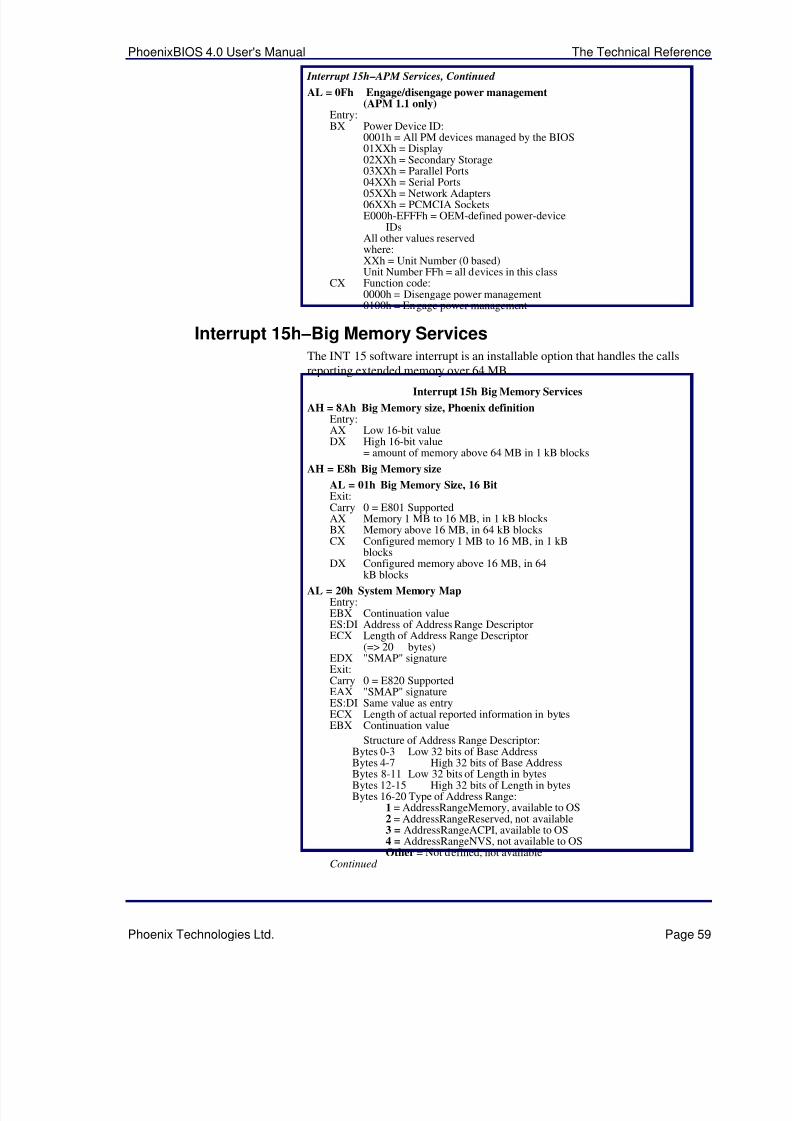
5/14/2018 PhoenixBIOS4_rev6UserMan - slidepdf.com
http://slidepdf.com/reader/full/phoenixbios4rev6userman 63/88
PhoenixBIOS 4.0 User's Manual The Technical Reference
Phoenix Technologies Ltd. Page 59
Interrupt 15h – APM Services, Continued
AL = 0Fh Engage/disengage power management(APM 1.1 only)
Entry:BX Power Device ID:
0001h = All PM devices managed by the BIOS01XXh = Display02XXh = Secondary Storage03XXh = Parallel Ports04XXh = Serial Ports05XXh = Network Adapters06XXh = PCMCIA SocketsE000h-EFFFh = OEM-defined power-device
IDsAll other values reservedwhere:XXh = Unit Number (0 based)Unit Number FFh = all devices in this class
CX Function code:0000h = Disengage power management0100h = Engage power management
Interrupt 15h –Big Memory ServicesThe INT 15 software interrupt is an installable option that handles the callsreporting extended memory over 64 MB.
Interrupt 15h Big Memory Services
AH = 8Ah Big Memory size, Phoenix definitionEntry:AX Low 16-bit valueDX High 16-bit value
= amount of memory above 64 MB in 1 kB blocks
AH = E8h Big Memory size
AL = 01h Big Memory Size, 16 BitExit: Carry 0 = E801 SupportedAX Memory 1 MB to 16 MB, in 1 kB blocksBX Memory above 16 MB, in 64 kB blocksCX Configured memory 1 MB to 16 MB, in 1 kB
blocks
DX Configured memory above 16 MB, in 64kB blocks
AL = 20h System Memory MapEntry:EBX Continuation valueES:DI Address of Address Range DescriptorECX Length of Address Range Descriptor
(=> 20 bytes)EDX "SMAP" signatureExit:Carry 0 = E820 SupportedEAX "SMAP" signatureES:DI Same value as entryECX Length of actual reported information in bytesEBX Continuation value
Structure of Address Range Descriptor:Bytes 0-3 Low 32 bits of Base AddressBytes 4-7 High 32 bits of Base AddressBytes 8-11 Low 32 bits of Length in bytesBytes 12-15 High 32 bits of Length in bytesBytes 16-20 Type of Address Range:
1 = AddressRangeMemory, available to OS2 = AddressRangeReserved, not available3 = AddressRangeACPI, available to OS4 = AddressRangeNVS, not available to OSOther = Not defined, not available
Continued

5/14/2018 PhoenixBIOS4_rev6UserMan - slidepdf.com
http://slidepdf.com/reader/full/phoenixbios4rev6userman 64/88
The Technical Reference PhoenixBIOS 4.0 User's Manual
Page 60 Phoenix Technologies Ltd.
Interrupt 15h – Big Memory Services, Continued
NOTE: Each call of this service defines a descriptor bufferand requests the memory status of the address rangespecified by the continuation value, where zero = first addressrange. The function fills the buffer and returns the continuationvalue for the next address range, where zero = lastaddress range.
AL = 81h Big Memory Size, 32-Bit Protected ModeExit:
Carry 0 = E881 supportedEAX Memory 1 MB to 16 MB, 1 kB blocksEBX Memory above 16 MB, 64 kB blocksECX Configured memory 1 MB to 16 MB, 1 kB
blocksEDX Configured memory above 16 MB, 64 kB
blocks
Interrupt 15h –PS/2 Mouse ServicesThe INT 15 software interrupt optionally supports systems with the PS/2 mouseor similar devices installed on the motherboard. The following table describesthe exit status codes:
PS/2 Mouse Exit Status Codes
AH 00h = No error01h = Invalid function call02h = Invalid input value03h = Interface error04h = Request for resend received from 804205h = No driver installed (i.e., Function C207
has not been called)
The following table describes the Interrupt 15h PS/2 mouse services of PhoenixBIOS 4.0:
Interrupt 15h PS/2 Mouse Services
AH = C2h PS/2 Mouse Support
AL 00 = Enable/Disable PS/2 MouseEntry:BH 00h = Disable
01h = Enable
AL 01 = Reset PS/2 MouseExit:BH Device ID
AL 02 = Set Sample RateEntry:BH Sample rate:
00h = 10 reports per second 01h = 20 reports per second 02h = 30 reports per second 03h = 40 reports per second 04h = 60 reports per second 04h = 80 reports per second 05h = 100 reports per second 06h = 200 reports per second
AL 03h = Set resolution
Entry:BH Resolution value:00h = 1 count per millimeter01h = 2 counts per millimeter02h = 4 counts per millimeter03h = 8 counts per millimeter
AL 04h = Read Device TypeExit:BH Device ID
AL 05h = Initialize PS/2 mouseEntry:BH Data package size (01-08h, in bytes)
Continued
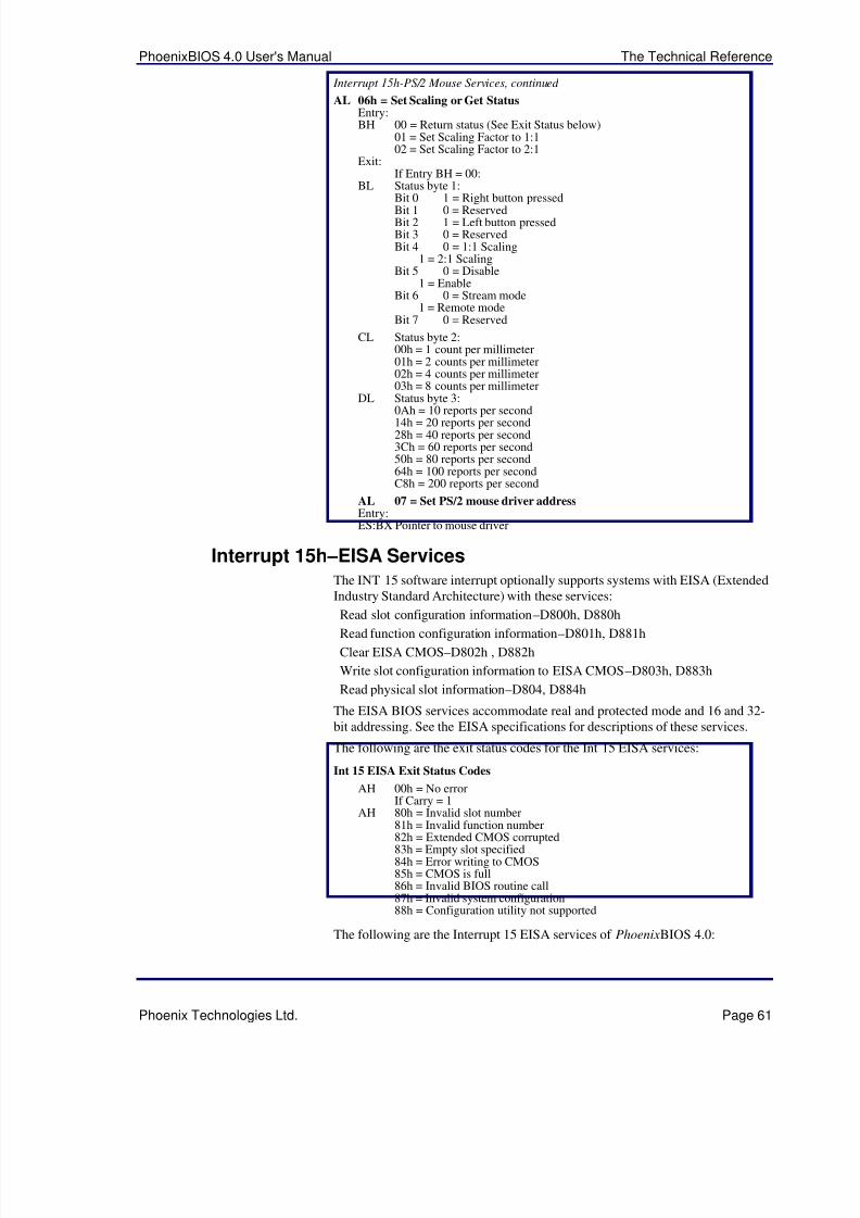
5/14/2018 PhoenixBIOS4_rev6UserMan - slidepdf.com
http://slidepdf.com/reader/full/phoenixbios4rev6userman 65/88
PhoenixBIOS 4.0 User's Manual The Technical Reference
Phoenix Technologies Ltd. Page 61
Interrupt 15h-PS/2 Mouse Services, continued
AL 06h = Set Scaling or Get StatusEntry:BH 00 = Return status (See Exit Status below)
01 = Set Scaling Factor to 1:102 = Set Scaling Factor to 2:1
Exit:If Entry BH = 00:
BL Status byte 1:Bit 0 1 = Right button pressedBit 1 0 = ReservedBit 2 1 = Left button pressedBit 3 0 = ReservedBit 4 0 = 1:1 Scaling
1 = 2:1 ScalingBit 5 0 = Disable
1 = EnableBit 6 0 = Stream mode
1 = Remote modeBit 7 0 = Reserved
CL Status byte 2:00h = 1 count per millimeter01h = 2 counts per millimeter02h = 4 counts per millimeter03h = 8 counts per millimeter
DL Status byte 3:
0Ah = 10 reports per second14h = 20 reports per second28h = 40 reports per second3Ch = 60 reports per second50h = 80 reports per second64h = 100 reports per secondC8h = 200 reports per second
AL 07 = Set PS/2 mouse driver addressEntry:ES:BX Pointer to mouse driver
Interrupt 15h –EISA ServicesThe INT 15 software interrupt optionally supports systems with EISA (ExtendedIndustry Standard Architecture) with these services:
Read slot configuration information–D800h, D880hRead function configuration information–D801h, D881h
Clear EISA CMOS–D802h , D882h
Write slot configuration information to EISA CMOS–D803h, D883h
Read physical slot information–D804, D884h
The EISA BIOS services accommodate real and protected mode and 16 and 32-bit addressing. See the EISA specifications for descriptions of these services.
The following are the exit status codes for the Int 15 EISA services:
Int 15 EISA Exit Status Codes
AH 00h = No errorIf Carry = 1
AH 80h = Invalid slot number
81h = Invalid function number82h = Extended CMOS corrupted83h = Empty slot specified84h = Error writing to CMOS85h = CMOS is full86h = Invalid BIOS routine call87h = Invalid system configuration88h = Configuration utility not supported
The following are the Interrupt 15 EISA services of PhoenixBIOS 4.0:
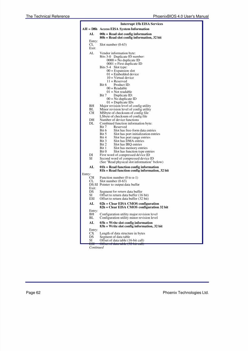
5/14/2018 PhoenixBIOS4_rev6UserMan - slidepdf.com
http://slidepdf.com/reader/full/phoenixbios4rev6userman 66/88
The Technical Reference PhoenixBIOS 4.0 User's Manual
Page 62 Phoenix Technologies Ltd.
Interrupt 15h EISA Services
AH = D8h Access EISA System Information
AL 00h = Read slot config information80h = Read slot config information, 32 bit
Entry:CL Slot number (0-63)Exit:
AL Vendor information byte:Bits 3-0 Duplicate ID number:
0000 = No duplicate ID0001 = First duplicate ID
Bits 5-4 Slot type:00 = Expansion slot01 = Embedded device10 = Virtual device11 = Reserved
Bit 6 Product ID:00 = Readable01 = Not readable
Bit 7 Duplicate ID:00 = No duplicate ID01 = Duplicate IDs
BH Major revision level of config utilityBL Minor revision level of config utilityCH MSbyte of checksum of config file
LSbyte of checksum of config fileDH Number of device functionsDL Combined function information byte:
Bit 7 ReservedBit 6 Slot has free-form data entriesBit 5 Slot has port initialization entriesBit 4 Slot has port range entriesBit 3 Slot has DMA entriesBit 2 Slot has IRQ entriesBit 1 Slot has memory entriesBit 0 Slot has function type entries
DI First word of compressed device IDSI Second word of compressed device ID
(See "Read physical slot information" below)
AL 01h = Read function config information81h = Read function config information, 32 bit
Entry:
CH Function number (0 to n-1)CL Slot number (0-63)DS:SI Pointer to output data bufferExit:DS Segment for return data bufferSI Offset to return data buffer (16 bit)ESI Offset to return data buffer (32 bit)
AL 02h = Clear EISA CMOS configuration82h = Clear EISA CMOS configuration 32 bit
Entry:BH Configuration utility major revision levelBL Configuration utility minor revision level
AL 03h = Write slot config information83h = Write slot config information, 32 bit
Entry:CX Length of data structure in bytes
DS Segment of data tableSI Offset of data table (16-bit call)ESI Offset of data table (32-bit call)Continued
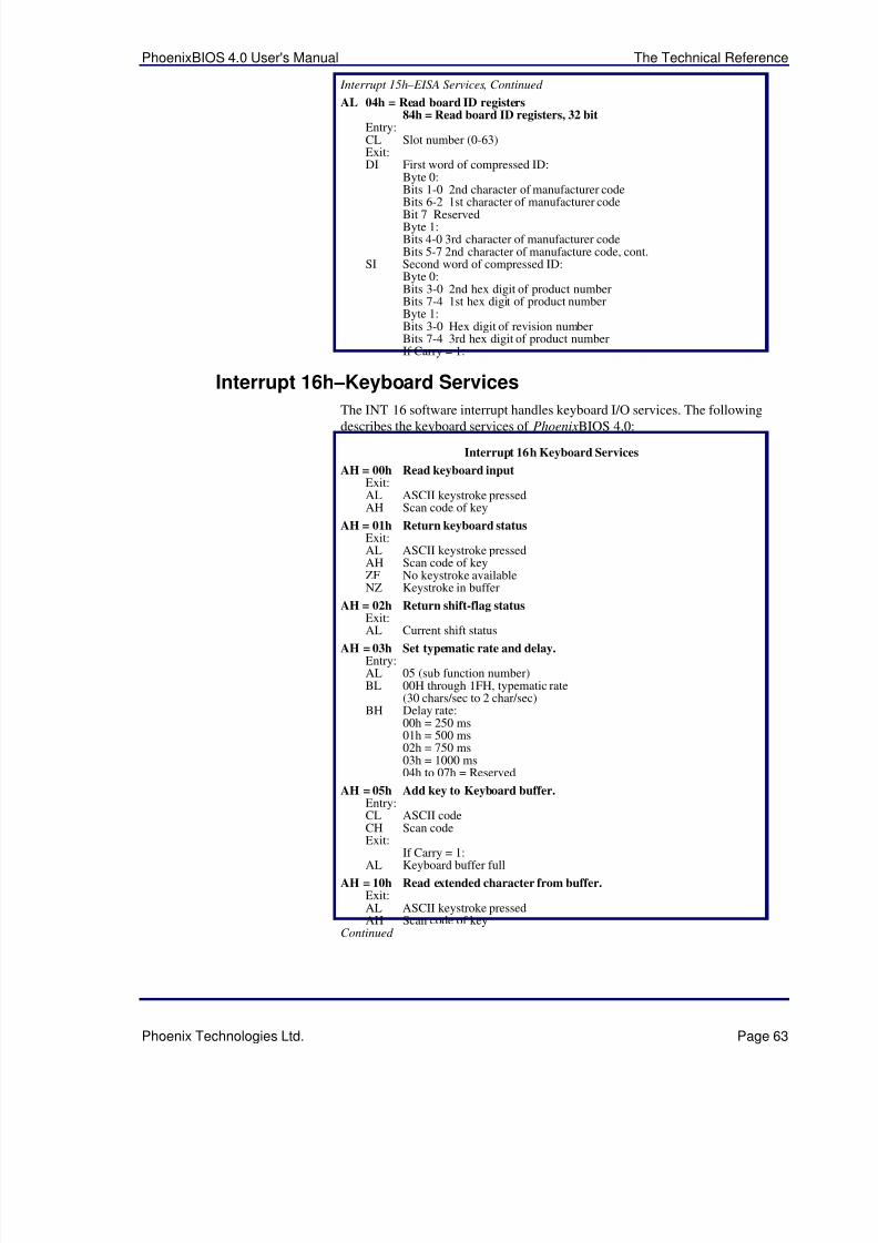
5/14/2018 PhoenixBIOS4_rev6UserMan - slidepdf.com
http://slidepdf.com/reader/full/phoenixbios4rev6userman 67/88
PhoenixBIOS 4.0 User's Manual The Technical Reference
Phoenix Technologies Ltd. Page 63
Interrupt 15h – EISA Services, Continued
AL 04h = Read board ID registers84h = Read board ID registers, 32 bit
Entry:CL Slot number (0-63)Exit:DI First word of compressed ID:
Byte 0:Bits 1-0 2nd character of manufacturer codeBits 6-2 1st character of manufacturer codeBit 7 ReservedByte 1:Bits 4-0 3rd character of manufacturer codeBits 5-7 2nd character of manufacture code, cont.
SI Second word of compressed ID:Byte 0:Bits 3-0 2nd hex digit of product numberBits 7-4 1st hex digit of product numberByte 1:Bits 3-0 Hex digit of revision numberBits 7-4 3rd hex digit of product numberIf Carry = 1:
Interrupt 16h –Keyboard Services
The INT 16 software interrupt handles keyboard I/O services. The followingdescribes the keyboard services of PhoenixBIOS 4.0:
Interrupt 16h Keyboard Services
AH = 00h Read keyboard inputExit:AL ASCII keystroke pressedAH Scan code of key
AH = 01h Return keyboard statusExit:AL ASCII keystroke pressedAH Scan code of keyZF No keystroke availableNZ Keystroke in buffer
AH = 02h Return shift-flag statusExit:
AL Current shift statusAH = 03h Set typematic rate and delay.
Entry:AL 05 (sub function number)BL 00H through 1FH, typematic rate
(30 chars/sec to 2 char/sec)BH Delay rate:
00h = 250 ms01h = 500 ms02h = 750 ms03h = 1000 ms04h to 07h = Reserved
AH = 05h Add key to Keyboard buffer.Entry:CL ASCII codeCH Scan code
Exit:If Carry = 1:
AL Keyboard buffer full
AH = 10h Read extended character from buffer.Exit:AL ASCII keystroke pressedAH Scan code of key
Continued
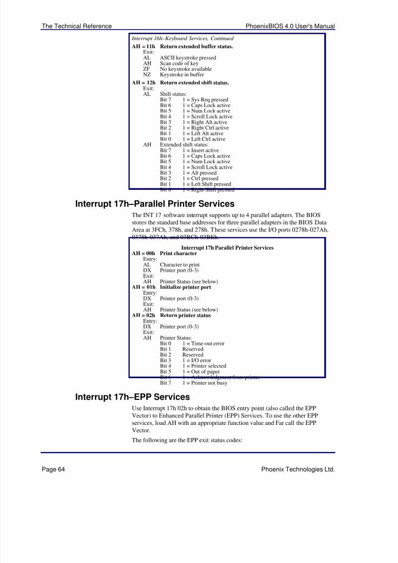
5/14/2018 PhoenixBIOS4_rev6UserMan - slidepdf.com
http://slidepdf.com/reader/full/phoenixbios4rev6userman 68/88
The Technical Reference PhoenixBIOS 4.0 User's Manual
Page 64 Phoenix Technologies Ltd.
Interrupt 16h –Keyboard Services, Continued
AH = 11h Return extended buffer status.Exit:AL ASCII keystroke pressedAH Scan code of keyZF No keystroke availableNZ Keystroke in buffer
AH = 12h Return extended shift status.Exit:
AL Shift status:Bit 7 1 = Sys Req pressedBit 6 1 = Caps Lock activeBit 5 1 = Num Lock activeBit 4 1 = Scroll Lock activeBit 3 1 = Right Alt activeBit 2 1 = Right Ctrl activeBit 1 1 = Left Alt activeBit 0 1 = Left Ctrl active
AH Extended shift status:Bit 7 1 = Insert activeBit 6 1 = Caps Lock activeBit 5 1 = Num Lock activeBit 4 1 = Scroll Lock activeBit 3 1 = Alt pressedBit 2 1 = Ctrl pressedBit 1 1 = Left Shift pressed
Bit 0 1 = Right Shift pressed
Interrupt 17h –Parallel Printer ServicesThe INT 17 software interrupt supports up to 4 parallel adapters. The BIOSstores the standard base addresses for three parallel adapters in the BIOS DataArea at 3FCh, 378h, and 278h. These services use the I/O ports 0278h-027Ah,0378h-037Ah, and 03BCh-03BEh.
Interrupt 17h Parallel Printer ServicesAH = 00h Print character
Entry:AL Character to printDX Printer port (0-3)Exit:AH Printer Status (see below)
AH = 01h Initialize printer portEntry:DX Printer port (0-3)Exit:AH Printer Status (see below)
AH = 02h Return printer statusEntry:DX Printer port (0-3)Exit:AH Printer Status:
Bit 0 1 = Time-out errorBit 1 ReservedBit 2 ReservedBit 3 1 = I/O errorBit 4 1 = Printer selectedBit 5 1 = Out of paperBit 6 1 = Acknowledgment from printerBit 7 1 = Printer not busy
Interrupt 17h –EPP ServicesUse Interrupt 17h 02h to obtain the BIOS entry point (also called the EPPVector) to Enhanced Parallel Printer (EPP) Services. To use the other EPPservices, load AH with an appropriate function value and Far call the EPPVector.
The following are the EPP exit status codes:
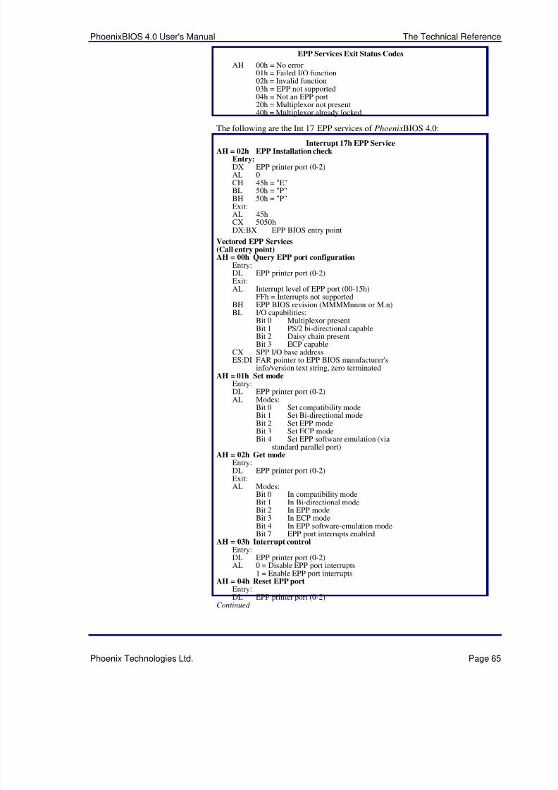
5/14/2018 PhoenixBIOS4_rev6UserMan - slidepdf.com
http://slidepdf.com/reader/full/phoenixbios4rev6userman 69/88
PhoenixBIOS 4.0 User's Manual The Technical Reference
Phoenix Technologies Ltd. Page 65
EPP Services Exit Status Codes
AH 00h = No error01h = Failed I/O function02h = Invalid function03h = EPP not supported04h = Not an EPP port20h = Multiplexor not present40h = Multiplexor already locked
The following are the Int 17 EPP services of PhoenixBIOS 4.0:
Interrupt 17h EPP ServiceAH = 02h EPP Installation check
Entry:DX EPP printer port (0-2)AL 0CH 45h = "E"BL 50h = "P"BH 50h = "P"Exit:AL 45hCX 5050hDX:BX EPP BIOS entry point
Vectored EPP Services(Call entry point)AH = 00h Query EPP port configuration
Entry:DL EPP printer port (0-2)Exit:AL Interrupt level of EPP port (00-15h)
FFh = Interrupts not supportedBH EPP BIOS revision (MMMMnnnn or M.n)BL I/O capabilities:
Bit 0 Multiplexor presentBit 1 PS/2 bi-directional capableBit 2 Daisy chain presentBit 3 ECP capable
CX SPP I/O base addressES:DI FAR pointer to EPP BIOS manufacturer's
info/version text string, zero terminatedAH = 01h Set mode
Entry:DL EPP printer port (0-2)
AL Modes:Bit 0 Set compatibility modeBit 1 Set Bi-directional modeBit 2 Set EPP modeBit 3 Set ECP modeBit 4 Set EPP software emulation (via
standard parallel port)AH = 02h Get mode
Entry:DL EPP printer port (0-2)Exit:AL Modes:
Bit 0 In compatibility modeBit 1 In Bi-directional modeBit 2 In EPP modeBit 3 In ECP modeBit 4 In EPP software-emulation mode
Bit 7 EPP port interrupts enabledAH = 03h Interrupt control
Entry:DL EPP printer port (0-2)AL 0 = Disable EPP port interrupts
1 = Enable EPP port interruptsAH = 04h Reset EPP port
Entry:DL EPP printer port (0-2)
Continued
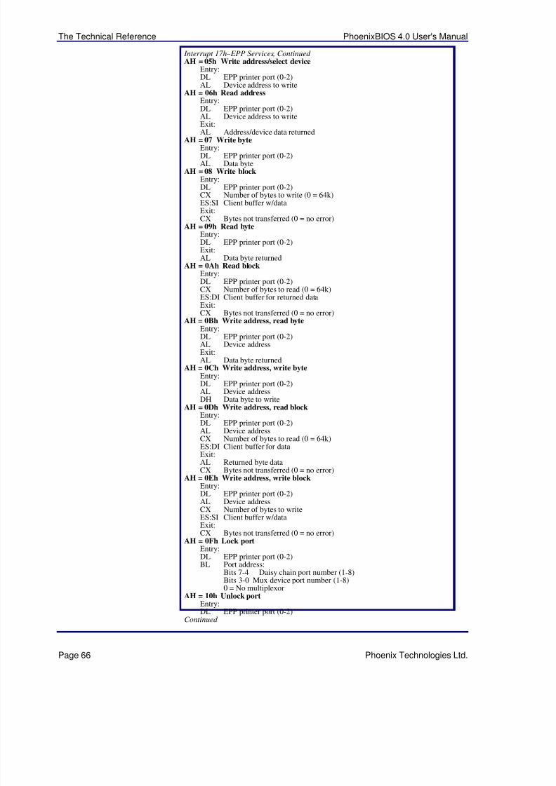
5/14/2018 PhoenixBIOS4_rev6UserMan - slidepdf.com
http://slidepdf.com/reader/full/phoenixbios4rev6userman 70/88
The Technical Reference PhoenixBIOS 4.0 User's Manual
Page 66 Phoenix Technologies Ltd.
Interrupt 17h – EPP Services, Continued AH = 05h Write address/select device
Entry:DL EPP printer port (0-2)AL Device address to write
AH = 06h Read addressEntry:DL EPP printer port (0-2)AL Device address to writeExit:
AL Address/device data returnedAH = 07 Write byte
Entry:DL EPP printer port (0-2)AL Data byte
AH = 08 Write blockEntry:DL EPP printer port (0-2)CX Number of bytes to write (0 = 64k)ES:SI Client buffer w/dataExit:CX Bytes not transferred (0 = no error)
AH = 09h Read byteEntry:DL EPP printer port (0-2)Exit:AL Data byte returned
AH = 0Ah Read blockEntry:DL EPP printer port (0-2)CX Number of bytes to read (0 = 64k)ES:DI Client buffer for returned dataExit:CX Bytes not transferred (0 = no error)
AH = 0Bh Write address, read byteEntry:DL EPP printer port (0-2)AL Device addressExit:AL Data byte returned
AH = 0Ch Write address, write byteEntry:DL EPP printer port (0-2)AL Device address
DH Data byte to writeAH = 0Dh Write address, read block
Entry:DL EPP printer port (0-2)AL Device addressCX Number of bytes to read (0 = 64k)ES:DI Client buffer for dataExit:AL Returned byte dataCX Bytes not transferred (0 = no error)
AH = 0Eh Write address, write blockEntry:DL EPP printer port (0-2)AL Device addressCX Number of bytes to writeES:SI Client buffer w/dataExit:
CX Bytes not transferred (0 = no error)AH = 0Fh Lock port
Entry:DL EPP printer port (0-2)BL Port address:
Bits 7-4 Daisy chain port number (1-8)Bits 3-0 Mux device port number (1-8)0 = No multiplexor
AH = 10h Unlock portEntry:DL EPP printer port (0-2)
Continued
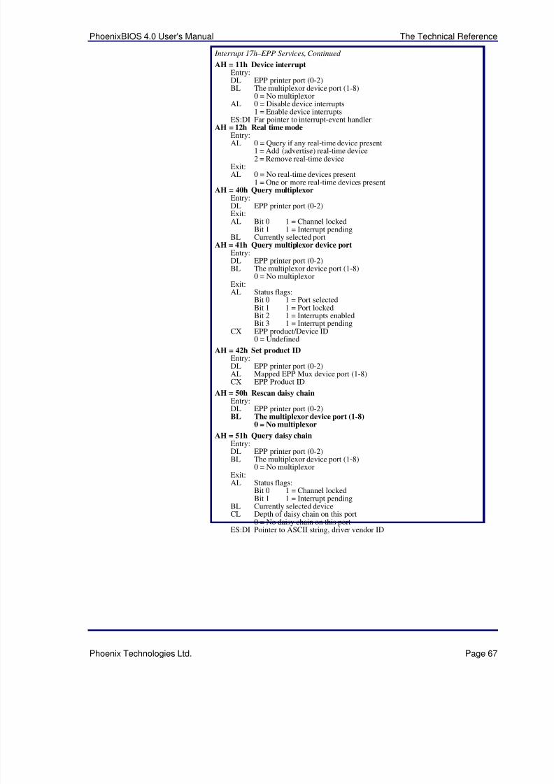
5/14/2018 PhoenixBIOS4_rev6UserMan - slidepdf.com
http://slidepdf.com/reader/full/phoenixbios4rev6userman 71/88
PhoenixBIOS 4.0 User's Manual The Technical Reference
Phoenix Technologies Ltd. Page 67
Interrupt 17h – EPP Services, Continued
AH = 11h Device interruptEntry:DL EPP printer port (0-2)BL The multiplexor device port (1-8)
0 = No multiplexorAL 0 = Disable device interrupts
1 = Enable device interruptsES:DI Far pointer to interrupt-event handler
AH = 12h Real time modeEntry:AL 0 = Query if any real-time device present
1 = Add (advertise) real-time device2 = Remove real-time device
Exit:AL 0 = No real-time devices present
1 = One or more real-time devices presentAH = 40h Query multiplexor
Entry:DL EPP printer port (0-2)Exit:AL Bit 0 1 = Channel locked
Bit 1 1 = Interrupt pendingBL Currently selected port
AH = 41h Query multiplexor device portEntry:DL EPP printer port (0-2)BL The multiplexor device port (1-8)
0 = No multiplexorExit:AL Status flags:
Bit 0 1 = Port selectedBit 1 1 = Port lockedBit 2 1 = Interrupts enabledBit 3 1 = Interrupt pending
CX EPP product/Device ID0 = Undefined
AH = 42h Set product IDEntry:DL EPP printer port (0-2)AL Mapped EPP Mux device port (1-8)CX EPP Product ID
AH = 50h Rescan daisy chainEntry:DL EPP printer port (0-2)BL The multiplexor device port (1-8)
0 = No multiplexor
AH = 51h Query daisy chainEntry:DL EPP printer port (0-2)BL The multiplexor device port (1-8)
0 = No multiplexorExit:AL Status flags:
Bit 0 1 = Channel lockedBit 1 1 = Interrupt pending
BL Currently selected deviceCL Depth of daisy chain on this port
0 = No daisy chain on this port
ES:DI Pointer to ASCII string, driver vendor ID
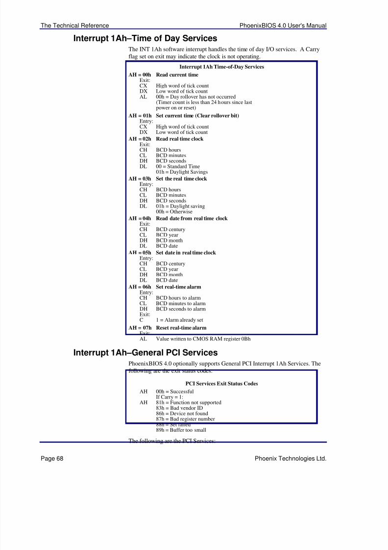
5/14/2018 PhoenixBIOS4_rev6UserMan - slidepdf.com
http://slidepdf.com/reader/full/phoenixbios4rev6userman 72/88
The Technical Reference PhoenixBIOS 4.0 User's Manual
Page 68 Phoenix Technologies Ltd.
Interrupt 1Ah –Time of Day ServicesThe INT 1Ah software interrupt handles the time of day I/O services. A Carryflag set on exit may indicate the clock is not operating.
Interrupt 1Ah Time-of-Day Services
AH = 00h Read current timeExit:CX High word of tick count
DX Low word of tick countAL 00h = Day rollover has not occurred(Timer count is less than 24 hours since lastpower on or reset)
AH = 01h Set current time (Clear rollover bit)Entry:CX High word of tick countDX Low word of tick count
AH = 02h Read real time clockExit:CH BCD hoursCL BCD minutesDH BCD secondsDL 00 = Standard Time
01h = Daylight Savings
AH = 03h Set the real time clock
Entry:CH BCD hoursCL BCD minutesDH BCD secondsDL 01h = Daylight saving
00h = Otherwise
AH = 04h Read date from real time clockExit:CH BCD centuryCL BCD yearDH BCD monthDL BCD date
AH = 05h Set date in real time clockEntry:CH BCD centuryCL BCD yearDH BCD month
DL BCD dateAH = 06h Set real-time alarm
Entry:CH BCD hours to alarmCL BCD minutes to alarmDH BCD seconds to alarmExit:C 1 = Alarm already set
AH = 07h Reset real-time alarmExit:AL Value written to CMOS RAM register 0Bh
Interrupt 1Ah –General PCI ServicesPhoenixBIOS 4.0 optionally supports General PCI Interrupt 1Ah Services. The
following are the exit status codes:
PCI Services Exit Status Codes
AH 00h = SuccessfulIf Carry = 1:
AH 81h = Function not supported83h = Bad vendor ID86h = Device not found87h = Bad register number88h = Set failed89h = Buffer too small
The following are the PCI Services:

5/14/2018 PhoenixBIOS4_rev6UserMan - slidepdf.com
http://slidepdf.com/reader/full/phoenixbios4rev6userman 73/88
PhoenixBIOS 4.0 User's Manual The Technical Reference
Phoenix Technologies Ltd. Page 69
Interrupt 1Ah General PCI Services
AH = B1h PCI Services
AL 01h = PCI BIOS presentExit:EDX "PCI", "P" in [DL], "C" in [DH], etc.AL Hardware mechanism:
Bit Description5 Spec. Cycle–Config Mechanism #2 support4 Spec. Cycle–Config Mechanism #1 support
1 Config Mechanism #2 support0 Config Mechanism #1 supportBH Interface level major versionBL Interface level minor versionCL Number of last PCI bus
AL 02h = Find PCI DeviceEntry:CX Device ID (0-65535)DX Vendor ID (0-65534)SI Index (0-n)Exit:BH Bus number (0-255)BL Bits 7-3 Device number
Bits 2-0 Function number
AL 03h = Find PCI class codeEntry:
ECX Class code in lower three bytesSI Index (0-n)Exit:BH Bus number (0-255)BL Bits 7-3 Device number
Bits 2-0 Function number
AL 06h = Generate special cycleEntry:BH Bus number (0-255)EDX Special cycle data
AL 08h = Read configuration byteEntry:BH Bus number (0-255)BL Bits 7-3 Device number
Bits 2-0 Function numberDI Register number (0-255)
Exit:CL Byte read
AL 09h = Read configuration wordEntry:BH Bus number (0-255)BL Bits 7-3 Device number
Bits 2-0 Function numberDI Register number (0, 2, 4,...254)Exit:CX Word read
AL 0Ah = Read configuration DwordEntry:BH Bus number (0-255)BL Bits 7-3 Device number
Bits 2-0 Function numberDI Register number (0, 4, 8,...252)
Exit:ECX Dword read
AL 0Bh = Write configuration byteEntry:BH Bus number (0-255)BL Bits 7-3 Device number
Bits 2-0 Function numberDI Register number (0-255)CL Byte value to writeContinued
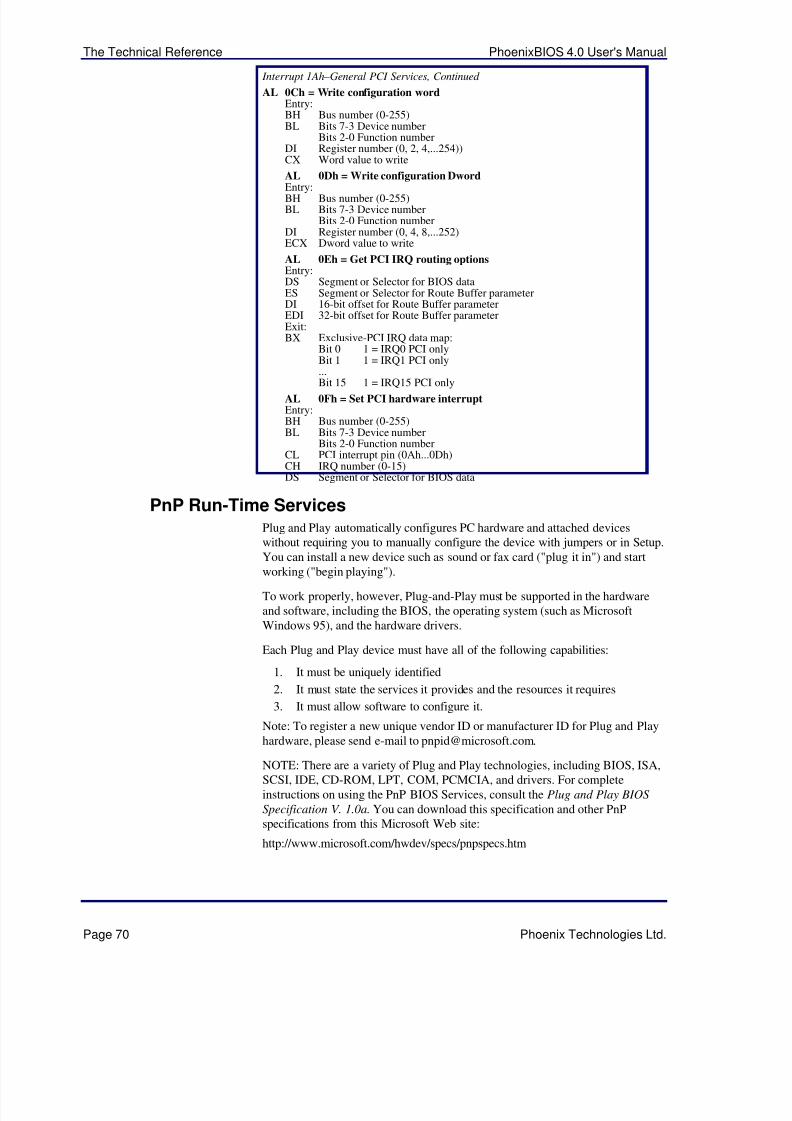
5/14/2018 PhoenixBIOS4_rev6UserMan - slidepdf.com
http://slidepdf.com/reader/full/phoenixbios4rev6userman 74/88
The Technical Reference PhoenixBIOS 4.0 User's Manual
Page 70 Phoenix Technologies Ltd.
Interrupt 1Ah –General PCI Services, Continued
AL 0Ch = Write configuration wordEntry:BH Bus number (0-255)BL Bits 7-3 Device number
Bits 2-0 Function numberDI Register number (0, 2, 4,...254))CX Word value to write
AL 0Dh = Write configuration Dword
Entry:BH Bus number (0-255)BL Bits 7-3 Device number
Bits 2-0 Function numberDI Register number (0, 4, 8,...252)ECX Dword value to write
AL 0Eh = Get PCI IRQ routing optionsEntry:DS Segment or Selector for BIOS dataES Segment or Selector for Route Buffer parameterDI 16-bit offset for Route Buffer parameterEDI 32-bit offset for Route Buffer parameterExit:BX Exclusive-PCI IRQ data map:
Bit 0 1 = IRQ0 PCI onlyBit 1 1 = IRQ1 PCI only...Bit 15 1 = IRQ15 PCI only
AL 0Fh = Set PCI hardware interruptEntry:BH Bus number (0-255)BL Bits 7-3 Device number
Bits 2-0 Function numberCL PCI interrupt pin (0Ah...0Dh)CH IRQ number (0-15)DS Segment or Selector for BIOS data
PnP Run-Time ServicesPlug and Play automatically configures PC hardware and attached deviceswithout requiring you to manually configure the device with jumpers or in Setup.You can install a new device such as sound or fax card ("plug it in") and start
working ("begin playing").
To work properly, however, Plug-and-Play must be supported in the hardwareand software, including the BIOS, the operating system (such as MicrosoftWindows 95), and the hardware drivers.
Each Plug and Play device must have all of the following capabilities:
1. It must be uniquely identified
2. It must state the services it provides and the resources it requires
3. It must allow software to configure it.
Note: To register a new unique vendor ID or manufacturer ID for Plug and Playhardware, please send e-mail to [email protected].
NOTE: There are a variety of Plug and Play technologies, including BIOS, ISA,SCSI, IDE, CD-ROM, LPT, COM, PCMCIA, and drivers. For completeinstructions on using the PnP BIOS Services, consult the Plug and Play BIOS
Specification V. 1.0a. You can download this specification and other PnPspecifications from this Microsoft Web site:
http://www.microsoft.com/hwdev/specs/pnpspecs.htm
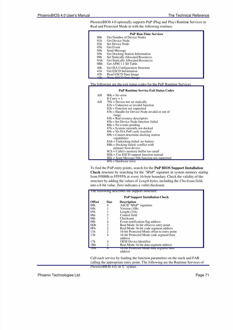
5/14/2018 PhoenixBIOS4_rev6UserMan - slidepdf.com
http://slidepdf.com/reader/full/phoenixbios4rev6userman 75/88
PhoenixBIOS 4.0 User's Manual The Technical Reference
Phoenix Technologies Ltd. Page 71
PhoenixBIOS 4.0 optionally supports PnP (Plug and Play) Runtime Services inReal and Protected Mode in with the following routines:
PnP Run-Time Services00h Get Number of Device Nodes01h Get Device Node02h Set Device Node03h Get Event04h Send Message05h Get Docking Station Information09h Set Statically Allocated Resources0Ah Get Statically Allocated Resources0Bh Get APM 1.1 ID Table
40h Get ISA Configuration Structure41h Get ESCD Information42h Read ESCD Data Image43h Write ESCD Data Image
The following are the exit status codes for the PnP Runtime Services
PnP Runtime Service Exit Status Codes
AH 00h = No errorIf Carry = 1:
AH 7Fh = Device not set statically81h = Unknown or invalid function82h = Function not supported
83h = Handle for Device Node invalid or out of range
84h = Bad resource descriptors85h = Set Device Node function failed86h = No events pending87h = System currently not docked88h = No ISA PnP cards installed89h = Cannot determine docking station
capabilities8Ah = Undocking failed: no battery8Bh = Docking failed: conflict with
primary boot device8Ch = Caller's memory buffer too small8Dh = Use ESCD support function instead8Eh = Send Message 04h function not supported8Fh = Hardware error
To find the PnP entry points, search for the PnP BIOS Support InstallationCheck structure by searching for the "$PnP" signature in system memory staringfrom F0000h to FFFFFh at every 16-byte boundary. Check the validity of thestructure by adding the values of Length bytes, including the Checksum field,into a 8-bit value. Zero indicates a valid checksum.
The following describes the support structure:
PnP Support Installation Check
Offset Size Description00h 4 ASCII "$PnP" signature04h 1 Version (10h)05h 1 Length (21h)06h 2 Control field08h 1 Checksum
09h 4 Event-notification flag address0Dh 2 Real Mode 16-bit offset to entry point0Fh 2 Real Mode 16-bit code segment address11h 2 16-bit Protected Mode offset to entry point13h 4 16-bit Protected Mode code segment base
address17h 4 OEM Device Identifier1Bh 2 Real Mode 16-bit data segment address1Dh 4 16-bit Protected Mode data segment base
address
Call each service by loading the function parameters on the stack and FARcalling the appropriate entry point. The following are the Runtime Services of PhoenixBIOS 4.0, in 'C' syntax.

5/14/2018 PhoenixBIOS4_rev6UserMan - slidepdf.com
http://slidepdf.com/reader/full/phoenixbios4rev6userman 76/88
The Technical Reference PhoenixBIOS 4.0 User's Manual
Page 72 Phoenix Technologies Ltd.
PnP Runtime-Service Function Parameters
00h Get Number of Device NodesEntry:int FAR (*entryPoint)(Function, NumNodes, NodeSize,BiosSelector);int Function;unsigned char FAR *NumNodes;unsigned int FAR *NodeSize;unsigned int BiosSelector;
01h Get System Device NodeEntry:int FAR (*entryPoint)(Function, Node, devNodeBuffer,Control, BiosSelector);int Function;unsigned char FAR *Node;struc DEV_NODE FAR *devNodeBuffer;unsigned int Control;unsigned int BiosSelector;
02h Set System Device NodeEntry:int FAR (*entryPoint)(Function, Node, devNodeBuffer,Control, BiosSelector);int Function;unsigned char Node;struc DEV_NODE FAR *devNodeBuffer;unsigned int Control;
unsigned int BiosSelector;03h Get Event
Entry:int FAR (*entryPoint)(Function, Message, BiosSelector);int Function;unsigned int FAR *Message;unsigned int BiosSelector;
04h Send MessageEntry:int FAR (*entryPoint)(Function, Message, BiosSelector);int Function;unsigned int Message:unsigned int BiosSelector;
05h Get Docking Station InformationEntry:int FAR (*entryPoint)(Function, DockingStationInfo,BiosSelector);
int Function;unsigned char FAR *DockingStationInfo;unsigned int BiosSelector;Exit:Docking station info buffer:
Offset 00h Docking station location identifierOffset 04h Serial NumberOffset 08h Docking Capabilities:Bits 2-1:
00 = Cold Docking01 = Warm Docking10 = Hot Docking
Bit 0:0 = Surprise-style docking1 = VCR-style docking
09h Set Statically Allocated ResourcesEntry:int FAR (*entryPoint)(Function, Resource Block,BiosSelector);int Function;unsigned char FAR *ResourceBlock;unsigned int BiosSelector;
Continued
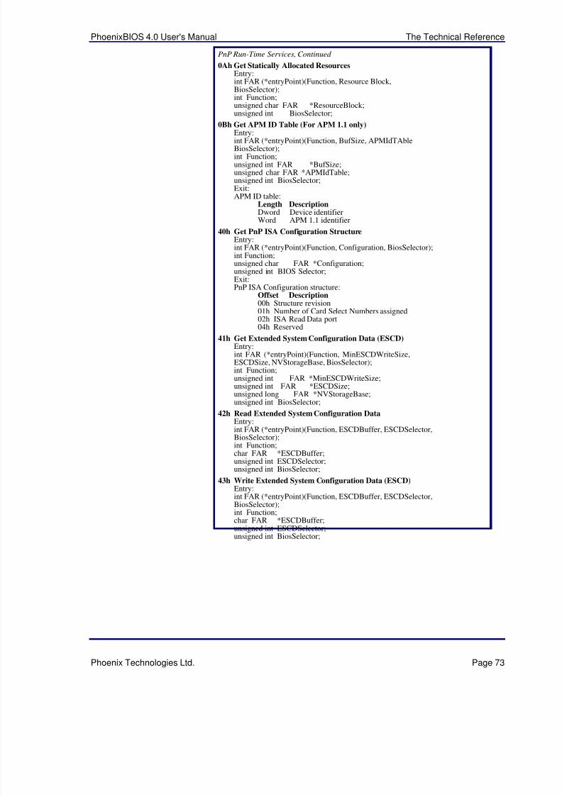
5/14/2018 PhoenixBIOS4_rev6UserMan - slidepdf.com
http://slidepdf.com/reader/full/phoenixbios4rev6userman 77/88
PhoenixBIOS 4.0 User's Manual The Technical Reference
Phoenix Technologies Ltd. Page 73
PnP Run-Time Services, Continued
0Ah Get Statically Allocated ResourcesEntry:int FAR (*entryPoint)(Function, Resource Block,BiosSelector);int Function;unsigned char FAR *ResourceBlock;unsigned int BiosSelector;
0Bh Get APM ID Table (For APM 1.1 only)
Entry:int FAR (*entryPoint)(Function, BufSize, APMIdTAbleBiosSelector);int Function;unsigned int FAR *BufSize;unsigned char FAR *APMIdTable;unsigned int BiosSelector;Exit:APM ID table:
Length DescriptionDword Device identifierWord APM 1.1 identifier
40h Get PnP ISA Configuration StructureEntry:int FAR (*entryPoint)(Function, Configuration, BiosSelector);int Function;unsigned char FAR *Configuration;unsigned int BIOS Selector;Exit:PnP ISA Configuration structure:
Offset Description00h Structure revision01h Number of Card Select Numbers assigned02h ISA Read Data port04h Reserved
41h Get Extended System Configuration Data (ESCD)Entry:int FAR (*entryPoint)(Function, MinESCDWriteSize,ESCDSize, NVStorageBase, BiosSelector);int Function;unsigned int FAR *MinESCDWriteSize;unsigned int FAR *ESCDSize;unsigned long FAR *NVStorageBase;
unsigned int BiosSelector;42h Read Extended System Configuration Data
Entry:int FAR (*entryPoint)(Function, ESCDBuffer, ESCDSelector,BiosSelector);int Function;char FAR *ESCDBuffer;unsigned int ESCDSelector;unsigned int BiosSelector;
43h Write Extended System Configuration Data (ESCD)Entry:int FAR (*entryPoint)(Function, ESCDBuffer, ESCDSelector,BiosSelector);int Function;char FAR *ESCDBuffer;unsigned int ESCDSelector;
unsigned int BiosSelector;
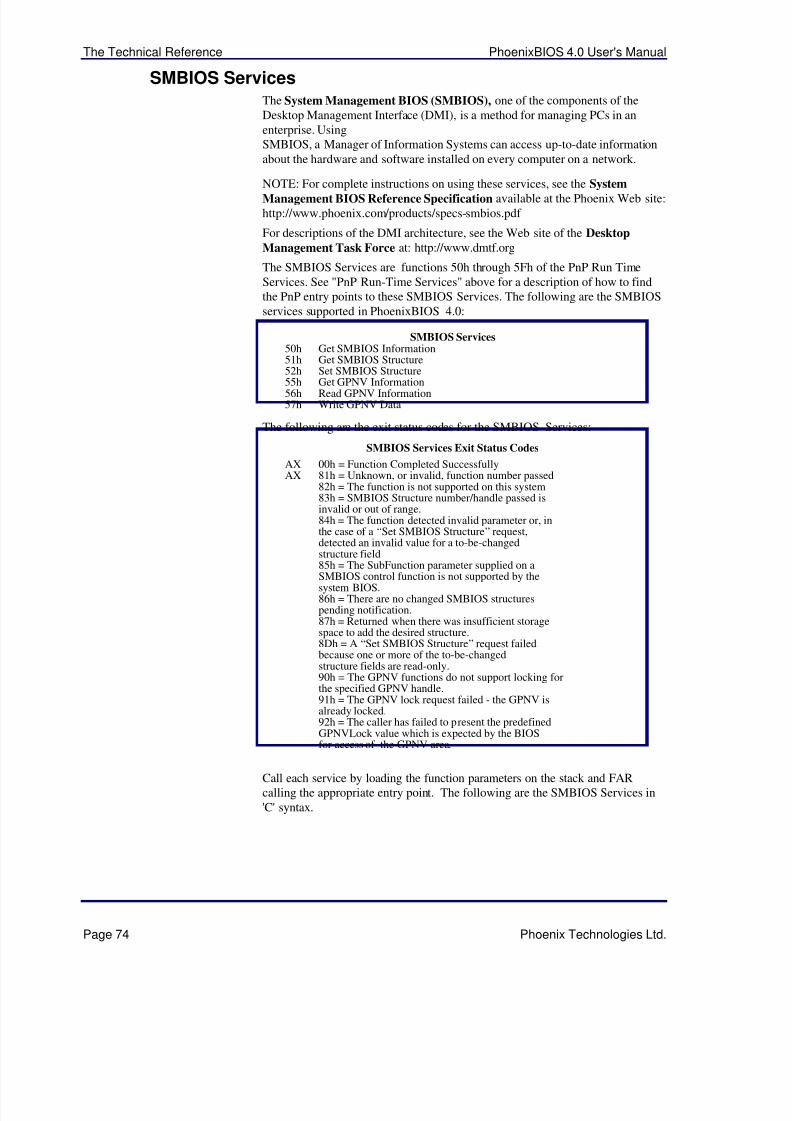
5/14/2018 PhoenixBIOS4_rev6UserMan - slidepdf.com
http://slidepdf.com/reader/full/phoenixbios4rev6userman 78/88
The Technical Reference PhoenixBIOS 4.0 User's Manual
Page 74 Phoenix Technologies Ltd.
SMBIOS ServicesThe System Management BIOS (SMBIOS), one of the components of theDesktop Management Interface (DMI), is a method for managing PCs in anenterprise. UsingSMBIOS, a Manager of Information Systems can access up-to-date informationabout the hardware and software installed on every computer on a network.
NOTE: For complete instructions on using these services, see the SystemManagement BIOS Reference Specification available at the Phoenix Web site:http://www.phoenix.com/products/specs-smbios.pdf
For descriptions of the DMI architecture, see the Web site of the Desktop
Management Task Force at: http://www.dmtf.org
The SMBIOS Services are functions 50h through 5Fh of the PnP Run TimeServices. See "PnP Run-Time Services" above for a description of how to findthe PnP entry points to these SMBIOS Services. The following are the SMBIOSservices supported in PhoenixBIOS 4.0:
SMBIOS Services50h Get SMBIOS Information51h Get SMBIOS Structure52h Set SMBIOS Structure55h Get GPNV Information56h Read GPNV Information57h Write GPNV Data
The following are the exit status codes for the SMBIOS Services:
SMBIOS Services Exit Status Codes
AX 00h = Function Completed SuccessfullyAX 81h = Unknown, or invalid, function number passed
82h = The function is not supported on this system83h = SMBIOS Structure number/handle passed isinvalid or out of range.84h = The function detected invalid parameter or, inthe case of a “Set SMBIOS Structure” request,detected an invalid value for a to-be-changedstructure field
85h = The SubFunction parameter supplied on aSMBIOS control function is not supported by thesystem BIOS.86h = There are no changed SMBIOS structurespending notification.87h = Returned when there was insufficient storagespace to add the desired structure.8Dh = A “Set SMBIOS Structure” request failedbecause one or more of the to-be-changedstructure fields are read-only.90h = The GPNV functions do not support locking forthe specified GPNV handle.91h = The GPNV lock request failed - the GPNV isalready locked.92h = The caller has failed to present the predefinedGPNVLock value which is expected by the BIOSfor access of the GPNV area.
Call each service by loading the function parameters on the stack and FARcalling the appropriate entry point. The following are the SMBIOS Services in'C' syntax.
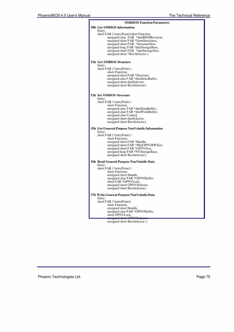
5/14/2018 PhoenixBIOS4_rev6UserMan - slidepdf.com
http://slidepdf.com/reader/full/phoenixbios4rev6userman 79/88
PhoenixBIOS 4.0 User's Manual The Technical Reference
Phoenix Technologies Ltd. Page 75
SMBIIOS Function Parameters
50h Get SMBIOS InformationEntry:short FAR (*entryPoint)(short Function,
unsigned char FAR *dmiBIOSRevision,unsigned short FAR *NumStructures,unsigned short FAR *StructureSize,unsigned long FAR *dmiStorageBase,unsigned short FAR *dmiStorageSize,unsigned short *BiosSelector );
51h Get SMBIOS StructureEntry:short FAR (*entryPoint) (
short Function;unsigned short FAR *Structure;unsigned char FAR *dmiStrucBuffer;unsigned short dmiSelector;unsigned short BiosSelector);
52h Set SMBIOS StructureEntry:short FAR (*entryPoint) (
short Function;unsigned char FAR *dmiDataBuffer,;
unsigned char FAR *dmiWorkBuffer,unsigned char Control,unsigned short dmiSelector;unsigned short BiosSelector);
55h Get General-Purpose NonVolatile Information Entry:short FAR (*entryPoint) (
short Function;unsigned short FAR *Handle,unsigned short FAR *MinGPNVRWSize,unsigned short FAR *GPNVSize,unsigned long FAR *NVStorageBase,unsigned short BiosSelector);
56h Read General-Purpose NonVolatile Data Entry:
short FAR (*entryPoint) (short Function;unsigned short Handle,unsigned char FAR *GPNVBuffer,short FAR *GPNVLock,unsigned short GPNVSelector,unsigned short BiosSelector);
57h Write General-Purpose NonVolatile Data Entry:short FAR (*entryPoint)(
short Function,unsigned short Handle,unsigned char FAR *GPNVBuffer,short GPNVLock,unsigned short GPNVSelector,unsigned short BiosSelector );
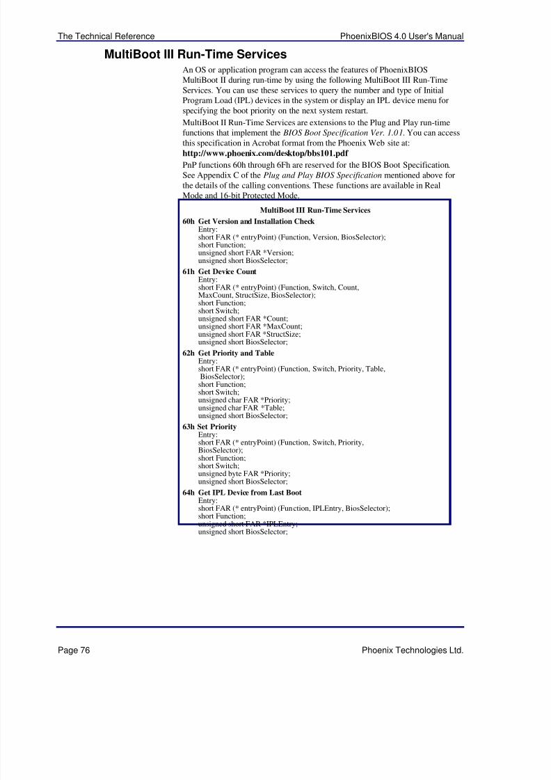
5/14/2018 PhoenixBIOS4_rev6UserMan - slidepdf.com
http://slidepdf.com/reader/full/phoenixbios4rev6userman 80/88
The Technical Reference PhoenixBIOS 4.0 User's Manual
Page 76 Phoenix Technologies Ltd.
MultiBoot III Run-Time ServicesAn OS or application program can access the features of PhoenixBIOSMultiBoot II during run-time by using the following MultiBoot III Run-TimeServices. You can use these services to query the number and type of InitialProgram Load (IPL) devices in the system or display an IPL device menu forspecifying the boot priority on the next system restart.
MultiBoot II Run-Time Services are extensions to the Plug and Play run-time
functions that implement the BIOS Boot Specification Ver. 1.01. You can accessthis specification in Acrobat format from the Phoenix Web site at:
http://www.phoenix.com/desktop/bbs101.pdf
PnP functions 60h through 6Fh are reserved for the BIOS Boot Specification.See Appendix C of the Plug and Play BIOS Specification mentioned above forthe details of the calling conventions. These functions are available in RealMode and 16-bit Protected Mode.
MultiBoot III Run-Time Services
60h Get Version and Installation CheckEntry:short FAR (* entryPoint) (Function, Version, BiosSelector);short Function;unsigned short FAR *Version;
unsigned short BiosSelector;61h Get Device Count
Entry:short FAR (* entryPoint) (Function, Switch, Count,MaxCount, StructSize, BiosSelector);short Function;short Switch;unsigned short FAR *Count;unsigned short FAR *MaxCount;unsigned short FAR *StructSize;unsigned short BiosSelector;
62h Get Priority and TableEntry:short FAR (* entryPoint) (Function, Switch, Priority, Table,BiosSelector);short Function;
short Switch;unsigned char FAR *Priority;unsigned char FAR *Table;unsigned short BiosSelector;
63h Set PriorityEntry:short FAR (* entryPoint) (Function, Switch, Priority,BiosSelector);short Function;short Switch;unsigned byte FAR *Priority;unsigned short BiosSelector;
64h Get IPL Device from Last BootEntry:short FAR (* entryPoint) (Function, IPLEntry, BiosSelector);short Function;
unsigned short FAR *IPLEntry;unsigned short BiosSelector;
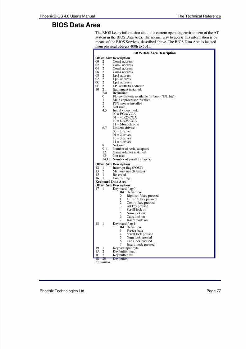
5/14/2018 PhoenixBIOS4_rev6UserMan - slidepdf.com
http://slidepdf.com/reader/full/phoenixbios4rev6userman 81/88
PhoenixBIOS 4.0 User's Manual The Technical Reference
Phoenix Technologies Ltd. Page 77
BIOS Data AreaThe BIOS keeps information about the current operating environment of the ATsystem in the BIOS Data Area. The normal way to access this information is bymeans of the BIOS Services, described above. The BIOS Data Area is locatedfrom physical address 400h to 501h.
BIOS Data Area Description
Offset Size Description00 2 Com1 address02 2 Com2 address04 2 Com3 address06 2 Com4 address08 2 Lpt1 address0A 2 Lpt2 address0C 2 Lpt3 address0E 2 LPT4/EBDA address*10 2 Equipment installed:
Bit Definition0 Floppy diskette available for boot ("IPL bit")1 Math coprocessor installed2 PS/2 mouse installed3 Not used4,5 Initial video mode:
00 = EGA/VGA
01 = 40x25 CGA10 = 80x25 CGA11 = Monochrome
6,7 Diskette drives:00 = 1 drive01 = 2 drives10 = 3 drives11 = 4 drives
8 Not used9-11 Number of serial adapters12 Game Adapter installed13 Not used14,15 Number of parallel adapters
Offset Size Description12 1 Interrupt flag (POST)13 2 Memory size (K bytes)15 1 Reserved16 1 Control flagKeyboard Data AreaOffset Size Description17 1 Keyboard flag 0:
Bit Definition0 Right shift key pressed1 Left shift key pressed2 Control key pressed3 Alt key pressed4 Scroll lock on5 Num lock on6 Caps lock on7 Insert mode on
18 1 Keyboard flag 1:Bit Definition3 Freeze state4 Scroll lock pressed5 Num lock pressed6 Caps lock pressed7 Insert mode pressed
19 1 Keypad input byte1A 2 Key buffer head1C 2 Key buffer tail1E 20 Key bufferContinued
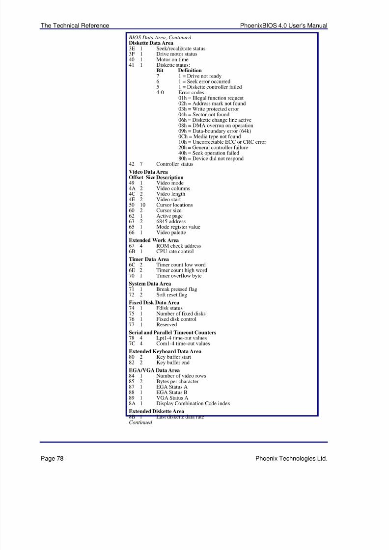
5/14/2018 PhoenixBIOS4_rev6UserMan - slidepdf.com
http://slidepdf.com/reader/full/phoenixbios4rev6userman 82/88
The Technical Reference PhoenixBIOS 4.0 User's Manual
Page 78 Phoenix Technologies Ltd.
BIOS Data Area, Continued Diskette Data Area3E 1 Seek/recalibrate status3F 1 Drive motor status40 1 Motor on time41 1 Diskette status:
Bit Definition7 1 = Drive not ready6 1 = Seek error occurred5 1 = Diskette controller failed
4-0 Error codes:01h = Illegal function request02h = Address mark not found03h = Write protected error04h = Sector not found06h = Diskette change line active08h = DMA overrun on operation09h = Data-boundary error (64k)0Ch = Media type not found10h = Uncorrectable ECC or CRC error20h = General controller failure40h = Seek operation failed80h = Device did not respond
42 7 Controller status
Video Data AreaOffset Size Description49 1 Video mode4A 2 Video columns4C 2 Video length4E 2 Video start50 10 Cursor locations60 2 Cursor size62 1 Active page63 2 6845 address65 1 Mode register value66 1 Video palette
Extended Work Area67 4 ROM check address6B 1 CPU rate control
Timer Data Area6C 2 Timer count low word6E 2 Timer count high word70 1 Timer overflow byte
System Data Area71 1 Break pressed flag72 2 Soft reset flag
Fixed Disk Data Area74 1 Fdisk status75 1 Number of fixed disks76 1 Fixed disk control77 1 Reserved
Serial and Parallel Timeout Counters78 4 Lpt1-4 time-out values7C 4 Com1-4 time-out values
Extended Keyboard Data Area80 2 Key buffer start82 2 Key buffer end
EGA/VGA Data Area84 1 Number of video rows85 2 Bytes per character87 1 EGA Status A88 1 EGA Status B89 1 VGA Status A8A 1 Display Combination Code index
Extended Diskette Area8B 1 Last diskette data rateContinued
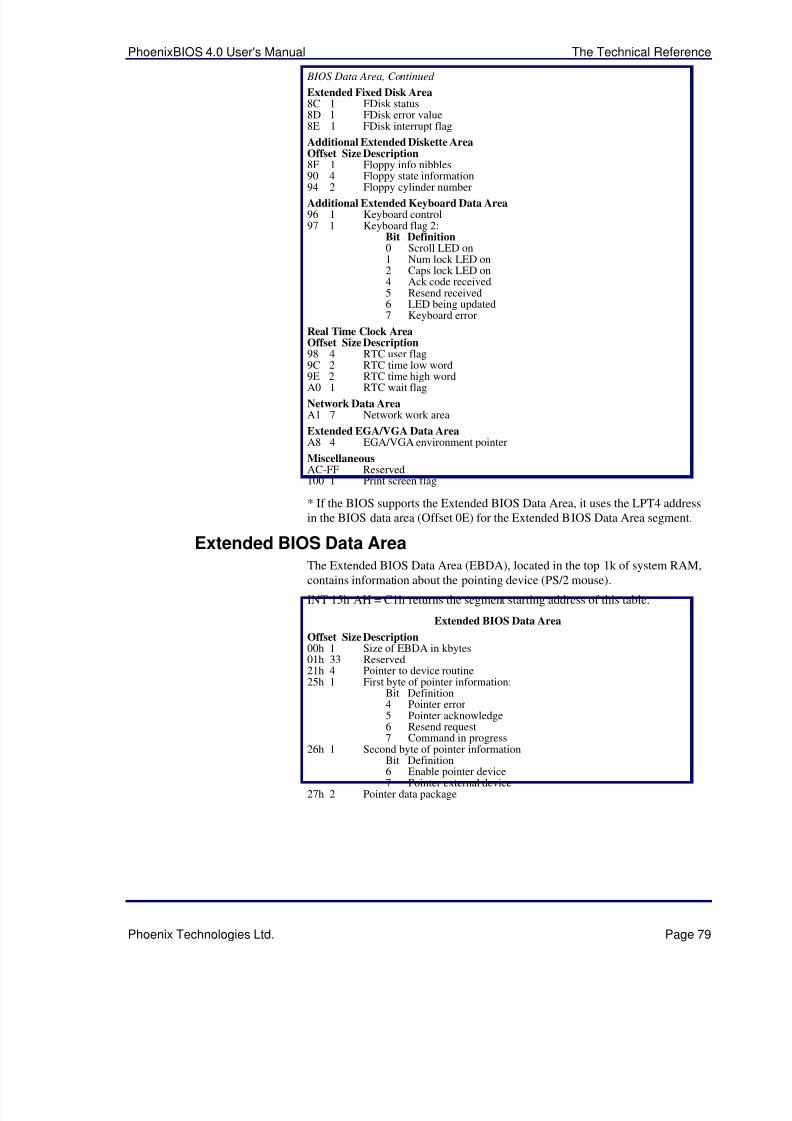
5/14/2018 PhoenixBIOS4_rev6UserMan - slidepdf.com
http://slidepdf.com/reader/full/phoenixbios4rev6userman 83/88
PhoenixBIOS 4.0 User's Manual The Technical Reference
Phoenix Technologies Ltd. Page 79
BIOS Data Area, Continued
Extended Fixed Disk Area8C 1 FDisk status8D 1 FDisk error value8E 1 FDisk interrupt flag
Additional Extended Diskette AreaOffset Size Description8F 1 Floppy info nibbles90 4 Floppy state information
94 2 Floppy cylinder numberAdditional Extended Keyboard Data Area96 1 Keyboard control97 1 Keyboard flag 2:
Bit Definition0 Scroll LED on1 Num lock LED on2 Caps lock LED on4 Ack code received5 Resend received6 LED being updated7 Keyboard error
Real Time Clock AreaOffset Size Description98 4 RTC user flag9C 2 RTC time low word
9E 2 RTC time high wordA0 1 RTC wait flag
Network Data AreaA1 7 Network work area
Extended EGA/VGA Data AreaA8 4 EGA/VGA environment pointer
MiscellaneousAC-FF Reserved100 1 Print screen flag
* If the BIOS supports the Extended BIOS Data Area, it uses the LPT4 addressin the BIOS data area (Offset 0E) for the Extended BIOS Data Area segment.
Extended BIOS Data Area
The Extended BIOS Data Area (EBDA), located in the top 1k of system RAM,contains information about the pointing device (PS/2 mouse).
INT 15h AH = C1h returns the segment starting address of this table.
Extended BIOS Data Area
Offset Size Description00h 1 Size of EBDA in kbytes01h 33 Reserved21h 4 Pointer to device routine25h 1 First byte of pointer information:
Bit Definition4 Pointer error5 Pointer acknowledge6 Resend request7 Command in progress
26h 1 Second byte of pointer information
Bit Definition6 Enable pointer device7 Pointer external device
27h 2 Pointer data package
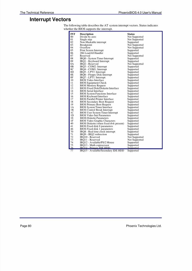
5/14/2018 PhoenixBIOS4_rev6UserMan - slidepdf.com
http://slidepdf.com/reader/full/phoenixbios4rev6userman 84/88
The Technical Reference PhoenixBIOS 4.0 User's Manual
Page 80 Phoenix Technologies Ltd.
Interrupt VectorsThe following table describes the AT system interrupt vectors. Status indicateswhether the BIOS supports the interrupt.
INT Description Status00 Divide by zero Not Supported01 Single step Not Supported02 Non-Maskable interrupt Supported
03 Breakpoint Not Supported04 Overflow Not Supported05 Print Screen Interrupt Supported06 286 LoadAll Handler Supported07 Reserved Not Supported08 IRQ0 - System Timer Interrupt Supported09 IRQ1 - Keyboard Interrupt Supported0A IRQ2 - Reserved Not Supported0B IRQ3 - COM2: Interrupt Supported0C IRQ4 - COM1: Interrupt Supported0D IRQ5 - LPT2: Interrupt Supported0E IRQ6 - Floppy Disk Interrupt Supported0F IRQ7 - LPT1: Interrupt Supported10 BIOS Video Interface Supported11 BIOS Equipment Check Supported12 BIOS Memory Request Supported13 BIOS Fixed Disk/Diskette Interface Supported
14 BIOS Serial Interface Supported15 BIOS System Functions Interface Supported16 BIOS Keyboard Interface Supported17 BIOS Parallel Printer Interface Supported18 BIOS Secondary Boot Request Supported19 BIOS Primary Boot Request Supported1A BIOS System Timer Interface Supported1B BIOS Control Break Interrupt Supported1C BIOS User System Timer Interrupt Supported1D BIOS Video Init Parameters Supported1E BIOS Diskette Parameters Supported1F BIOS Video Graphic Characters Supported40 BIOS Diskette (when fixed disk present) Supported41 BIOS Fixed disk 0 parameters Supported46 BIOS Fixed disk 1 parameters Supported70 IRQ8 - Real time clock interrupt Supported71 IRQ9 - IRQ2 redirection Supported
72 IRQ10 - Reserved Not Supported73 IRQ11 - Reserved Not Supported74 IRQ12 - Available/PS/2 Mouse Supported75 IRQ13 - Math coprocessor Supported76 IRQ14 - Primary IDE HDD Supported77 IRQ15 - Available/Secondary IDE HDD Supported
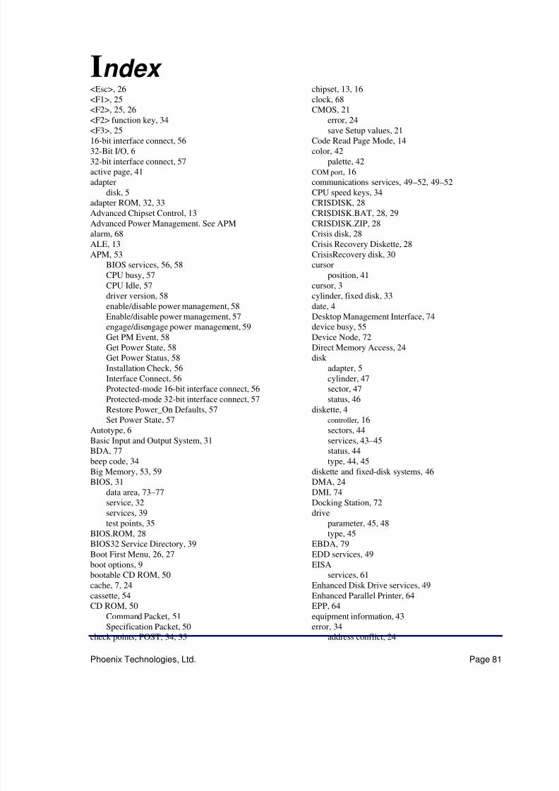
5/14/2018 PhoenixBIOS4_rev6UserMan - slidepdf.com
http://slidepdf.com/reader/full/phoenixbios4rev6userman 85/88
Phoenix Technologies, Ltd. Page 81
Index <Esc>, 26<F1>, 25<F2>, 25, 26<F2> function key, 34
<F3>, 2516-bit interface connect, 5632-Bit I/O, 632-bit interface connect, 57active page, 41adapter
disk, 5adapter ROM, 32, 33Advanced Chipset Control, 13Advanced Power Management. See APMalarm, 68ALE, 13APM, 53
BIOS services, 56, 58CPU busy, 57CPU Idle, 57driver version, 58enable/disable power management, 58Enable/disable power management, 57engage/disengage power management, 59Get PM Event, 58Get Power State, 58Get Power Status, 58Installation Check, 56Interface Connect, 56Protected-mode 16-bit interface connect, 56
Protected-mode 32-bit interface connect, 57Restore Power_On Defaults, 57Set Power State, 57
Autotype, 6Basic Input and Output System, 31BDA, 77beep code, 34Big Memory, 53, 59BIOS, 31
data area, 73–77service, 32services, 39test points, 35
BIOS.ROM, 28BIOS32 Service Directory, 39Boot First Menu, 26, 27boot options, 9bootable CD ROM, 50cache, 7, 24cassette, 54CD ROM, 50
Command Packet, 51Specification Packet, 50
check points, POST, 34, 35
chipset, 13, 16clock, 68CMOS, 21
error, 24
save Setup values, 21Code Read Page Mode, 14color, 42
palette, 42COM port, 16communications services, 49–52, 49–52CPU speed keys, 34CRISDISK, 28CRISDISK.BAT, 28, 29CRISDISK.ZIP, 28Crisis disk, 28Crisis Recovery Diskette, 28CrisisRecovery disk, 30
cursorposition, 41cursor, 3cylinder, fixed disk, 33date, 4Desktop Management Interface, 74device busy, 55Device Node, 72Direct Memory Access, 24disk
adapter, 5cylinder, 47sector, 47
status, 46diskette, 4
controller, 16sectors, 44services, 43–45status, 44type, 44, 45
diskette and fixed-disk systems, 46DMA, 24DMI, 74Docking Station, 72drive
parameter, 45, 48
type, 45EBDA, 79EDD services, 49EISA
services, 61Enhanced Disk Drive services, 49Enhanced Parallel Printer, 64EPP, 64equipment information, 43error, 34
address conflict, 24
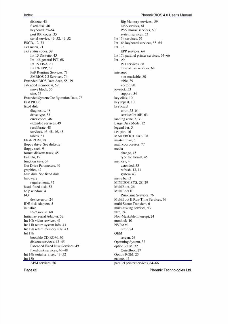
5/14/2018 PhoenixBIOS4_rev6UserMan - slidepdf.com
http://slidepdf.com/reader/full/phoenixbios4rev6userman 86/88
Index PhoenixBIOS 4.0 User's Manual
Page 82 Phoenix Technologies Ltd.
diskette, 43fixed disk, 46keyboard, 55–64port 80h codes, 35serial service, 49–52, 49–52
ESCD, 12, 73exit menu, 21exit status codes, 39
Int 13 Diskette, 43Int 14h general PCI, 68Int 15 EISA, 61Int17h EPP, 65PnP Runtime Services, 71SMBIOS 2.2 Services, 74
Extended BIOS Data Area, 55, 79extended memory, 4, 59
move block, 55size, 55
Extended System Configuration Data, 73Fast PIO, 6fixed disk
diagnostic, 48drive type, 33error codes, 46extended services, 49recalibrate, 48services, 46–48, 46, 48tables, 33
Flash ROM, 28floppy drive. See diskettefloppy seek, 9format diskette track, 45Full On, 19function keys, 34
Get Drive Parameters, 49graphics, 42hard disk. See fixed disk hardware
requirements, 32head, fixed disk, 33help window, 4I/O
device error, 24IDE disk adapters, 5initialize
PS/2 mouse, 60Initialize Serial Adapter, 52
Int 10h video services, 41Int 11h return system info, 43Int 12h return memory size, 43Int 13h
bootable CD ROM, 50diskette services, 43–45Extended Fixed Disk Services, 49fixed disk services, 46–48
Int 14h serial services, 49–52Int 15h
APM services, 56
Big Memory services., 59EISA services, 61PS/2 mouse services, 60system services, 53
Int 15h services, 79Int 16h keyboard services, 55–64Int 17h
EPP services, 64
Int 17h parallel printer services, 64–66Int 1Ah
PCI services, 68time of day services, 68
interruptnon-maskable, 80table, 39vector, 80
joystick, 53support, 54
key click, 10key repeat, 10keyboard
error, 55–64servicesInt16H, 63
landing zone, 5, 33Large Disk Mode, 12legend bar, 3LPT port, 16MAKEBOOT.EXE, 28master drive, 5math coprocessor, 77media
change, 45type for format, 45
memory, 4
extended, 53refresh, 13, 14system, 43
menu bar, 3MINIDOS.SYS, 28, 29MultiBoot, 26MultiBoot II
Run-Time Services, 76MultiBoot II Run-Time Services, 76multi-Sector Transfers, 6multi-tasking services, 53NMI, 24Non-Maskable Interrupt, 24
numlock, 10NVRAM
error, 24OEM
screen, 26Operating System, 32option ROM, 32
QuietBoot, 27Option ROM, 25palette, 42parallel printer services, 64–66
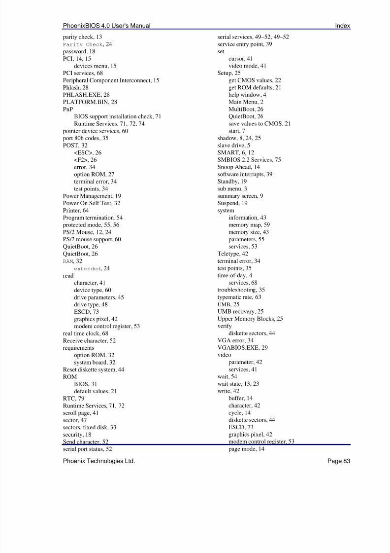
5/14/2018 PhoenixBIOS4_rev6UserMan - slidepdf.com
http://slidepdf.com/reader/full/phoenixbios4rev6userman 87/88
PhoenixBIOS 4.0 User's Manual Index
Phoenix Technologies Ltd. Page 83
parity check, 13Parity Check, 24password, 18PCI, 14, 15
devices menu, 15PCI services, 68Peripheral Component Interconnect, 15Phlash, 28
PHLASH.EXE, 28PLATFORM.BIN, 28PnP
BIOS support installation check, 71Runtime Services, 71, 72, 74
pointer device services, 60port 80h codes, 35POST, 32
<ESC>, 26<F2>, 26error, 34option ROM, 27terminal error, 34
test points, 34Power Management, 19Power On Self Test, 32Printer, 64Program termination, 54protected mode, 55, 56PS/2 Mouse, 12, 24PS/2 mouse support, 60QuietBoot, 26QuietBoot, 26RAM, 32
extended, 24
read
character, 41device type, 60drive parameters, 45drive type, 48ESCD, 73graphics pixel, 42modem control register, 53
real time clock, 68Receive character, 52requirements
option ROM, 32system board, 32
Reset diskette system, 44
ROMBIOS, 31default values, 21
RTC, 79Runtime Services, 71, 72scroll page, 41sector, 47sectors, fixed disk, 33security, 18Send character, 52serial port status, 52
serial services, 49–52, 49–52service entry point, 39set
cursor, 41video mode, 41
Setup, 25get CMOS values, 22get ROM defaults, 21
help window, 4Main Menu, 2MultiBoot, 26QuietBoot, 26save values to CMOS, 21start, 7
shadow, 8, 24, 25slave drive, 5SMART, 6, 12SMBIOS 2.2 Services, 75Snoop Ahead, 14software interrupts, 39Standby, 19
sub menu, 3summary screen, 9Suspend, 19system
information, 43memory map, 59memory size, 43parameters, 55services, 53
Teletype, 42terminal error, 34test points, 35time-of-day, 4
services, 68troubleshooting, 35typematic rate, 63UMB, 25UMB recovery, 25Upper Memory Blocks, 25verify
diskette sectors, 44VGA error, 34VGABIOS.EXE, 29video
parameter, 42services, 41
wait, 54wait state, 13, 23write, 42
buffer, 14character, 42cycle, 14diskette sectors, 44ESCD, 73graphics pixel, 42modem control register, 53page mode, 14

5/14/2018 PhoenixBIOS4_rev6UserMan - slidepdf.com
http://slidepdf.com/reader/full/phoenixbios4rev6userman 88/88
Index PhoenixBIOS 4.0 User's Manual
Page 84 Phoenix Technologies Ltd.
pixel, 42precomp, 6, 33string, 42teletype, 42