ph.d. thesis abstract 1990-1881 - iit kanpur. thesis abstract 1990...ph.d. thesis abstract 1990-1881...
TRANSCRIPT
1
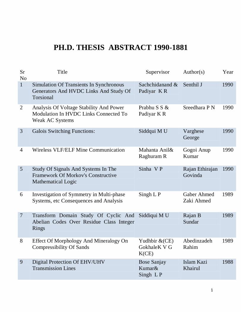
PH.D. THESIS ABSTRACT 1990-1881
Sr
No
Title Supervisor Author(s) Year
1 Simulation Of Transients In Synchronous
Generators And HVDC Links And Study Of
Torsional
Sachchidanand &
Padiyar K R
Senthil J 1990
2 Analysis Of Voltage Stability And Power
Modulation In HVDC Links Connected To
Weak AC Systems
Prabhu S S &
Padiyar K R
Sreedhara P N 1990
3 Galois Switching Functions: Siddqui M U Varghese
George
1990
4 Wireless VLF/ELF Mine Communication Mahanta Anil&
Raghuram R
Gogoi Anup
Kumar
1990
5 Study Of Signals And Systems In The
Framework Of Morkov's Constructive
Mathematical Logic
Sinha V P
Rajan Ethirajan
Govinda
1990
6 Investigation of Symmetry in Multi-phase
Systems, etc Consequences and Analysis
Singh L P
Gaber Ahmed
Zaki Ahmed
1989
7 Transform Domain Study Of Cyclic And
Abelian Codes Over Residue Class Integer
Rings
Siddiqui M U
Rajan B
Sundar
1989
8 Effect Of Morphology And Mineralogy On
Compressibility Of Sands
Yudhbir &(CE)
GokhaleK V G
K(CE)
Abedinzadeh
Rahim
1989
9 Digital Protection Of EHV/UHV
Transmission Lines
Bose Sanjay
Kumar&
Singh L P
Islam Kazi
Khairul
1988

2
10 Control Of Static VAR Systems For
Improvement Of Dynamic Stability And
Damping Of Torsional Oscillations
Padiyar K R
Varma Rajiv
Kumar
1988
11 GTO Convertor FED DC Motor Drives Doradla S R&
Dubey G K
Khan Badrul
Hasan
1988
12 Standard Cell Placement And Routing Hasan M M&
Dhande Sanjay
Govind(ME)
Rao D
Sreenivasa
1988
13 Direct Stability Evaluation And On-Line
Dynamic Security Asstssment Of Power
Systems Using Structure Preserving Energy
Functions
Padiyar K R
Ghosh K K 1987
14 Finite Deconvolution Data Recovery
Schemes For Block Data Communication
Over Dispersive Channel
Siddiqui M U Poonacha P G 1986
15 Optimal Control Systems Design With
Vector-Valued Performance Index
Sarkar B
Nandakumar,
M P
1986
16 Multi Phase (II-PHASE) Systems: Dynamical
Modelling And Analysis
Singh L P
Choudhary
Madan Mohan
1986
17 Power Factor Improvement And Harmonic
Reduction In Thyristor Converters
Dubey G K Patel Hirabha
K
1985
18 Analysis And Of Simulation HVDC-Turbine
Generator Torsional Interactions Padiyar K R
KothariA G 1985
19 Investigations Into The Design Of Power
System Stabilizers
Padiyar K R
&Prabhu S S
Anwar
Anwaruddin
1985
20 Linear Sequential SystemS Over Residue
Class Polynomial Rings: Theory And
Applications
Siddiqui M U Bhat K N Hari 1985

3
21 Selection Of Nominal Point For LQSF
Regulator And Determination Of Parameter
Range For A Specified Suboptimality
Hole K E Mahanta
Prafulla
Chandra
1985
22 Reactive Power Control And Security
Analysis Of Power Systems
Padiyar K R&
Aggarwal R P
Jose T 1985
23 On The Phoshorus Diffusion In Silicon In
Oxidising And Chloro-Oxidising Ambients
Tyagi M S
Gupta A K 1984
24 Novel Distance Relaying Schemes For The
Protection Of Ehv/Uhv Transmission Lines
Using Digital Techniques
Dubey G K&
Singh L P
Kellogg Anug
Jaiprakash
1984
25 Application Of Topological Energy Functions
For The Direct Stability Evaluation Of Power
Systems
Padiyar K R Sastry H S Y 1984
26 Analysis Of Sub-synchronous Resonance
And Its Control Through Excitation System
Gupta Sumana&
Padiyar K R
Chanana M L 1983
27 Anaysis Of New Types Of Waveguide And
Microstrip Discontiruity Structures and their
Practical Applications
C Das Gupta TomarR S 1983
29 Origins Of Excess Forward And Reverse
Currents In Silicon Diffused Junction Solar
Cells
Sharan R Lal Rakesh K 1983
30 Ultra High Speed Protection Relaying
Schemes For EHV/UHV Transmission Lines
Based On Travelling Wave Phenomena
Singh L P Desikachar
Kandala
Vedanta
1983
31 Fully Controlled Converter With Controlled
Wheeling
Dubey G K Subbanna Bhat
P
1983
32 Broadband Microstrip Antennas Using
Coupled Resonators
Gupta K C Kumar Girish 1982

4
33 Digital Simulation And Stability Analysis Of
Multi Terminal HVDC Systems
Padiyar K R Sachchidanand 1982
34 Microwave Measurements Of Complex
Dielectrfic Constant Of Solod And Liquid
Films
C Das Gupta Pramanick
Protap
1982
35 Mathematical Modelling And Analysis Of
Six-Phase (Multi-phase) Power Systems
Singh L P Tiwari Shri
Niwas
1982
36 Reliability Evaluation And Planning Of Bulk
Power Systems
Padiyar K R Shanbhag R S 1982
37 Desegmentation Method And Its Applications
To Circularly Polarized Microstrip Antennas
Gupta K C
Sharma
Pramod
Chandra
1982
38 Analysis Of Power System Dynamic Stability
Influenced Loads And Thyristor Controlled
Var Compensators
Padiyar K R Rajasekharm P 1982
39 Analysis And Design Of Vlf Antennas Raghuram R &
Mathur Naresh C
Rajasekharm P 1982
40 A Study Of Over Voltage Problems In Ehv
Systems
Aggarwal RP &
Padiyar K R
Saxena N S 1981
41 Synthesis Of Active R Filters, Oscillators
And Delay Networks
Venkateswaran
Shankara
Venkataramani
Y
1981
42 Determination Of Effective Device
Parameters Of silicon Juncition Field Effect
Transistors
Sharan R&
Biswas R N
Nandi Prasanta
Kumar
1981
43 Analysis And Performance Of Chopper-Fed
D. C. Motors Under Motoring And
Regenerative Braking
Dubey G K&
Singh L P
Satpathi H 1981

5
44 Triangular Segments And Two Dimensional
Analysis For Microwave Integrated Circuits
Gupta K C Chadha Rakesh 1981
45 Optimal Control And Parameter
Determination In Volterra Type Integral And
Delay Differential Systems
Prabhu S S&
Das Purna
Chandra (Math &
Stats)
Patel Nalini
Kumar
1981
46 Design Performance And optimization Of
Reflection-Type In Diode Phase Shifters
Gupta K C Trivedi Devesh
Kumar
1981

6
Title : Simulation Of Transients In Synchronous Generators And HVDC
Links And Study Of Torsional
Author(s) : Senthil J
Roll No : 8410466
Supervisor(s) : Sachchidanand & Padiyar K R
Abstract
High voltage Direct Current (HVDC) power transmission has been in use all over the world
since the first Gotland link was commissioned in 1954. this is in a large measure due to the
development of high power tryristor valves and novel control techniques. The economic design
and optimal operation of an HVDC system requires detailed investigation of the dynamic
performance of the system both under steady state and transient conditions and the performance
evaluation of converter controls under various system conditions. Although an HVDC simulator
(physical model) can be used and they do offer several advantages in terms of realistic controller
models and fast interactive computation, the cost of these simulators is prohibitive to be used on
a large scale. Digital simulators on the other hand offer significant benefits in terms of cost and
flexibility. Thus, digital simulation can be used to supplement the HVDC simulator. Among the
several different digital simulation programs which have been reported for the transient analysis
of AC/DC systems, the Electromagnetic transients program (EMTP) [1] has come to be accepted
internationally. Programs similar to EMTP but more specialized have also been developed [2].
Transient analysis of AC/DC systems using a digital computer requires modeling of the various
subcomponents depending on the nature of study. For example, for the study of switching surges
which persist for a very short duration, a simple model of a synchronous generator behind a sub
transient reactance is adequate. However, study of transient phenomena persisting over longer
periods such as those of sub synchronous resonance between the mechanical electrical systems
require detailed synchronous machine models. Although, a lot of work has been reported in the
literature in the area of transient analysis of AC/DC systems with simplified AC system
representation, digital computer study of transients in synchronous generators and HVDC links
has not received much attention. Digital simulation of transients in synchronous generators and
HVDC links requires detailed representation of machine, its associated torsional shaft dynamics,
the HVDC system and the converter controls. The synchronous machine equations are nonlinear
in nature. Hence, the solution of synchronous machine with the network equations which are
handled using the Dommel’s approach [1], requires suitable interface technique. The interface
techniques reported in the literature can be classified as requiring either the Thevenin equivalent
of the network as seen from the generator [7] or the Thevenin equivalent of the generator
themselves [8,9]. The method described in (7) has the drawback that if there are more than one
synchronous machines in the network, their mode is should be separated by distributed parameter
lines. This is because, superposition of node voltage is valid only if the system as seen from
synchronous machine terminal is linear. The drawbacks of (7) are avoided by considering the

7
Thevenin equivalent of the generator as described in [8,9]. In this approach the emf term is to be
predicted by the prediction of d and q components of either the stator currents or the stator flux-
linkages and the rotor speed. Since the stator windings are connected to the network, any drastic
change which occurs on the network side will be reflected on the stator flux-linkages. The
numerical stability of the interface can be enhanced by having an interface algorithm which
relies on the prediction of rotor flux-linkages rather than the stator flux-linkages and also by
avoiding the prediction of rotor speed. Converter controls form an essential part of any HVDC
system. The design of adequate control system must take into account the HVDC-AC system
interactions. The possibility of adverse HVDC-turbine-generator interaction was discovered only
recently. The first experience of such interaction occurred at the Square Butte DC project when
the DC link operated radically [4]. It was found that there is a potential for torsional instability
when a turbine-generator has a torsional mode whose frequency is within the bandwidth of
HVDC current controllers which is typically around 10-30 Hz. Subsequently, HVDC simulator
studies were performed to understand this phenomenon and identify parameters affecting it. The
Phenomenon of sub synchronous resonance (SSR) in series compensated AC systems has been
studied in depth using digital simulation programs and a lot of insight has been gained into this.
There is however not much work reported on the study of HVDC-turbine-generator interactions
using digital computers. Recently Padiyar and Kothari [5] have analyzed this phenomenon using
dynamic digital simulation with detailed representation of generator and its mechanical system.
However, in their study, the inverter of the DC system is represented by a constant DC voltage
source. Also, the effect of auxiliary Sub synchronous Damping Controllers (SSDC) in reducing
the torsional oscillations has not been investigated. Generators connected at the HVDC inverter
bus are subject to problems of power reversal on load-rejection. Nakra et al [3] conducted studies
on hydro-generators using HVDC simulator to understand this phenomenon, based on their
studies they have suggested modifications in the converter control to reduce the resulting shaft
stress. However, before the necessary control modifications are incorporated, detailed study is
necessary to analyze the effectiveness of the control strategy in reducing the transients. The
objective of the work reported in this thesis are: 1) To carry out digital computer studies of
torsional interactions in turbo-generators connected to HVDC links (at the rectifier or inverter).
Studies of this nature are important because many physical simulators do not have the feature for
detailed representation of the synchronous generators with its associated torsional shaft
dynamics. 2) To develop a digital simulation program for the transient analysis of AC/DC
system with detailed representation of synchronous generators and the DC system. Since the
BPA EMTP was not available, a transient analysis program along the lines suggested by
Dommel had to be developed. 3) To present an improved method for interfacing synchronous
generator mode with Electromagnetic Transients Program. The major contribution of the thesis
are as follows: 1) A new technique, which relies on the prediction of rotor flux-linkages, for
interfacing synchronous generator models with an electromagnetic transients program. 2)
Development of a digital computer program for the transient analysis of AC/Dc systems. The
program incorporates detailed representation of converter and its controls, the AC and DC
systems, and the synchronous generator with its associated mechanical system. Results of transient

8
analysis of a two-terminal HVDC system obtained using the digital simulation program are validated by
studies on a physical simulator. 3) Study of the HVDC-torsional interactions through digital dynamic
simulation and investigation of the effect of subsynchronous damping controllers in reducing torsional
oscillations. 4) Digital computer study of converter control strategy for reducing stresses on the shafts of
turbo-generators connected to HVDC inverter bus. A brief description of the work reported in the thesis is
given below: The first chapter introduces the various aspects studied and presents literature survey in this
area. Chapter two describes a new technique for interfacing synchronous machine models with an
electromagnetic transients program. this is based on the synchronous machine is represented by constant
(subtransient) inductances in parallel with current sources which are dependent on rotor flux-linkages.
The machine model handles subtransient saliency by introducing an additional dummy coil on the rotor q-
axis. The machine inductances in parallel with the current source are constants and can therefore be
included with the rest of the network. The influence of the time step on the accuracy, and the inclusion of
AVR on the interface technique is analyzed. The validity of the proposed interface technique is tested on
a sample network. Chapter 3 deals with the development of a digital simulation program based on
Dommel’s approach [1] for transient simulation of network and the generator models described in the
previous chapter. The transients program incorporates detailed representation of converter along with its
associated controls, and the AC and DC system models. The transients programs has been tested from the
case study of a wo-terminal HVDC system reported in [10]. Chapter 4 is concerned with the simulation of
HVDC system on the physical simulator at Central Power Research Institute, Bangalore. The scaling
procedure on the simulator, and the setting up of various system components such as infinite bus,
transmission lines, filters, converter transformers, converters and their controls are illustrated. The results
of the case study reported in chapter 3 are validated by studies on the physical simulator. In this study, the
generator has been modeled as an infinite bus. The various test cases which have been considered for
validation are remote three phase-to-ground faults, single phase-to-ground faults, and three phase-to-
ground faults both at the rectifier as well as the inverter bus. Chapter 5 reports on the digital computer
study of HVDC-torsional interaction in a two-terminal radial HVDC system with detailed representation
of rectifier and inverter, and their associated controls. The generator and its associated mechanical system
is represented in detail. Auxiliary subsynchronous damping controller (SSDC) with signal derived from
rotor speed has been considered. plots of frequency spectrum of the shaft torques are given to illustrate
the effect of SSDC in reducing the torsional stress. Chapter 6 describes the digital computer study of
transients in turbo-generators connected to HVDC inverter bus. In the even of load – rejection, the effect
of ramping down the inverter DC voltage in reducing the shaft stress and the dynamic overvoltages in
investigated. Chapter 7 outlines the conclusions drawn from the thesis and gives suggestions for further
work in this area.
For more details click here Back

9
Title : Analysis Of Voltage Stability And Power Modulation In HVDC
Links Connected To Weak AC Systems
Author(s) : Sreedhara P N
Roll No : 8410468
Supervisor(s) : Prabhu S S & Padiyar K R
Abstract
Since the advent of thyristor valves and related developments, the application of High Voltage Direct
Current (HVDC) links for the expansion of power transmission systems has been on the increase. In
particular, use of HVDC links are proved to be advantageous for long distance bulk power transmission
ad AC system interconnection. The benefits accruing from asynchronous interconnection for AC system
integration is well recognized. Most of the existing HVDC links are two terminal systems for
transmission of power from point-to-point. Recently, there is a growing interest in Multi-Terminal DC
(MTDC) transmission systems because of flexibility of system operation. New MTDC transmission
systems are being planned. The tapping at Corsica of the existing Sardinia-Italy link is a specific example
of MTDC operation and a five terminal Hydro Quebec – New England system is under construction. It
can be expected that the application of MTDC systems will increase in future. HVDC systems can also be
used to augment the stability of interconnected AC systems by fast modulation of power flow in the link.
Power transmitted through the DC link is independent of bus angles but depends only on bus voltage and
control setting (current or power). Control settings can be changed almost instantaneously through the
electronic converter controls. If the set current or power is modulated by a suitable external control signal
(ECS) derived from bus frequency or other AC system quantities the resulting variation in the power flow
through DC link can help in damping out oscillations in the AC system. However, the effectiveness of DC
link modulation depends on strength of AC system at the inverter bus. The strength of AC system at a
converter bus is measured in terms of short Circuit Ratio (SCR). Short circuit ratio is defined as the ratio
o fundamental short circuit capacity of AC system at converter bus to the rated power of DC link. If SCR
is less than three, the AC system is considered to the weak. A weak AC system is characterized by large
equivalent impedance as seen from converter terminals. Low short circuit ratios are more commonly
encountered with asynchronous DC links. If the AC system in which the DC link is embedded in weak,
additional problems arise in the operation of DC link [1]. Problems of concern are: (i) voltage instability,
(ii) dynamic (temporary) over voltage, (iii) harmonic instability, (iv) increased incidence of commutation
failure in inverters, (v) loss of effectiveness of power modulation, (vi) restrictions on the recovery rate
after shut down of DC link. Of these, voltage instability is one of the major operational problems.
Transient or steady state stability is defined as the ability of a power system to operate stably without loss
of synchronism among generators after a large or small disturbance respectively. On the other hand
voltage stability is the ability of the system to maintain load voltage magnitudes within specified
operating limits under steady state conditions [2]. Maintaining converter bus voltage magnitude within
operating limits under all conditions of operation of DC link is a major problem if the host AC system is
weak. This problem calls for detailed investigation at the planning stage of DC link. To overcome the
problem of voltage instability in AC-DC systems, two remedial measures have been proposed. These are
(i) to adopt alternative control strategy for converter control, or (ii) to use a static var system (SVS) at
10
converter bus. In a two terminal DC link, normally rectifier will be on current control and the inverter on
constant extinction angle (CEA) control. The CEA control has the advantages of minimum voltage ratings
and losses in the converter valves and minimum reactive power requirements. However, the major
disadvantage of CEA control is the negative resistance characteristics of inverter as seen from rectifier
terminals. Weaker the AC system at the inverter, more pronounced will be the negative resistance
characteristics. Few of the novel inverter control strategies mentioned in literature are: (i) constant AC
voltage control, (ii) a constant DC voltage control, (iii) constant reactive current control, (iv) constant
reactive power control. Some of these control techniques have already been implemented in some of the
existing systems. Alternatively, a well designed SVS installed at converter bus can alleviate voltage
instability. The effectiveness of current or power modulation in a DC link reduced as the AC system
connected to the inverter becomes weak. This is due to the fact that the DC current modulation at the
rectifier is accompanied by inadvertent and counteracting modulation of the DC voltage at the inverter
which is caused by the variation of the AC voltage magnitude. In the case of synchronous HVDC link, the
modulation of DC link power can be partially offset by the accompanying modulation current in the
parallel AC link when the SCRs at both rectifier and inverter are low. One of the techniques suggested for
improving the effectiveness of the power modulation in DC link is to introduce gama modulation with
control signal derived from the inverter bus AC voltage. In general, in a two terminal HVDC, link the
auxiliary controllers can be employed along with the converter controller at both terminals in order to
modulate alpha at the rectifier and gama at the inverter. It is to be expected that two auxiliary controllers
give a better performance than a single controller. Power modulation is also beneficial with asynchronous
HVDC links in damping electro-mechanical oscillations in the associated AC systems. Here, the bus
frequency signal (derived from rectifier and inverter bus) can be used individually instead of a difference
signal which is used in synchronous HVDC links. The objective of this thesis are: (i) To investigate in
depth the steady state and dynamic voltage instability problem in AC-DC systems in both two terminal
and multi-terminal DC (MTDC) systems. (ii) To investigate the effectiveness of power modulation and
damping control in synchronous and asynchronous HVDC links connected to weak AC systems. The
voltage instability problem can be analyzed (i) using only algebraic equations, (ii) using dynamic
equations. In both cases the equations are linearized around an operating point. The dynamic analysis is
more comprehensive and stability can be judged by the location of the eigenvalues of the linearized
system. Although appearing to be simplistic, the steady state analysis can provide a fast and reasonably
accurate method for identifying potential voltage instability problems. Yoshida [3] has used a simple
dynamic analysis employing Routh-Hurwitz criterism for a two terminal HVDC link with CEA control at
the inverter. However, the analysis considers only the earlier proportional type and not the present day
proportional-integral (P-I) type controllers. Also the novel inverter controller and SVS controllers have
not been considered. Recently Hammed et al [4] have presented a new approach for the steady state
analysis at inverter bus of a two terminal HVDC link. They define a criterism for voltage instability based
on the computation of Voltage Stability Factor (VSF). This is used to investigate the performance of a
novel inverter controller based on AC voltage regulation. However, this analysis has not been extended
for alternate inverter controllers and MTDC systems. While there are several papers for the design of
auxiliary controllers for power modulation in HVDC link, a detailed study of the alpha and/or gama
modulation in synchronous and asynchronous HVDC links connected to weak AC systems has not been
reported. The major contributions of the research work are as follows. (i) A novel and basic approach for
the dynamic analysis of voltage instability problem in HVDC-AC systems using a block diagram
retaining the identity of individual converter controllers. By defining a set of constants (analogous to

11
Heffron-Philips constants) that depend on the operating conditions and system parameters, the concept of
voltage stability are clarified. (ii) A detailed and comparative study of the voltage instability at the
inverter bus (of a two terminal HVDC link) with different converter controls and static var system
control. (iii) Generalization of the concept of voltage stability factors for the analysis of voltage stability
of MTDC systems. (iv) The investigation of rectifier current and inverter gama modulation in two
terminal synchronous links in improving the damping of electro-mechanical oscillations. Different control
signals derived from the frequency, generator rotor velocity and converter bus AC voltage are considered.
The effectiveness of the modulation as a function of the network impedance is studied. The outline of the
work reported in the thesis is given below: (i) In the first chapter, some of the problems of concern for
operation of high voltage direct current links in weak AC systems are discussed. Power modulation is
presented. The scope and objectives of the thesis are outlined along with the chapter-wise summary of
work reported in the thesis. (ii) In the second state analysis, rectifier is assumed to be either on constant
current control or on constant power control. The concept of the voltage stability factor [4] defined at the
inverter bus is used for stability study of system with different operating conditions. The operating point
is changed either by changing the power transmitted by the DC link at a fixed SCR at converters or by
changing the inverter SCR when DC link is transferring the rated power. The influence of AC system
impedance angle on voltage stability is investigated. In dynamic voltage stability analysis, the system is
represented by a bloc diagram retaining the identify of converter controllers. The block diagram constants
are evaluated at different operating points obtained by varying the AC system impedance magnitude on
the inverter side. The rectifier is assumed to be on constant control. The DC link is considered to be fully
loaded as this condition presents worst situation as far as the voltage stability is concerned. Two different
converter control structures are considered in the analysis. These are (i) Proportional-Integral (P-I)
controllers with a compensator and (ii) Proportional-Controller. The dynamic equations of the system are
derived in terms of block diagram constants and the system state matrix is obtained. Eigenvalue analysis
is employed for stability characterization of system. The effects of converter control parameters, SCR on
inverter side and dynamics of a synchronous generator on inverter side are presented with the help of a
case study. In the last part of this chapter a comparison is made between steady state and dynamic voltage
stability analysis by deriving the system transfer function in terms of block diagram constants. 3. Chapter
three deals with dynamic voltage stability analysis of asynchronous DC link with novel inverter controls.
In this, constant AC voltage control, constant DC voltage control and constant reactive current control at
the inverter are considered. The system representation using the block diagram given in Chapter 2 is
considered for the analysis. The controller structure is assumed to be P-I type for rectifier current
controller and inverter controllers. The DC link is assumed to be at its rated and the operating point is
changed by changing the SCR on inverter side. The state equations are derived in terms of block diagram
constants and the state matrix is obtained. Eigenvalue is used for voltage stability study of the system.
The influence of AC system strength on rectifier side, AC system strength on inverter side and control
parameters on voltage stability characteristics of the system are investigated. A static var system of fixed
capacitor-tyristor controlled reactor (FC-TCR) configuration is considered at inverter AC bus to study its
influence on voltage stability of the system. In this case, the inverter is assumed to be on constant
extinction angle control. The VSF is computed as the steady state value of the transfer function between
AC voltage magnitude and the reactive power injection at the inverter bus. 4. In chapter four, steady state
voltage stability analysis of multi-terminal DC systems is considered. A general formulation for the
steady state voltage stability analysis of n-terminal DC systems is presented by defining a matrix VSF
with self and mutual terms. A two terminal HVDC link is a particular case in the above formulation. Of

12
the n-terminals of a MTDC system, any one terminal can be selected as voltage setting terminal (VST).
The following control strategies are considered at the voltage setting terminal. Constant (i) AC voltage
control, (ii) DC voltage control, (iii) extinction angle control, (iv) reactive current control, (v) reactive
power control and (vi) power factor control. All other (n-1) terminals are considered to be either on (a)
constant current control, or (b) constant power control. The analysis is illustrated by taking up examples
of (i) a two terminal link and (ii) a four terminal system. The effect of choice of VST, control strategy
adopted at VST and control strategy employed at other terminals on voltage stability characteristics of the
system are investigated. 5. Rectifier current and/or gama modulation of two terminal synchronous and
asynchronous links in influencing system stable region of operation and damping of synchronous
generator rotor oscillations are discussed in chapter five. In the case of asynchronous HVDC link, the
synchronous generator is considered on the inverter side. The following signals are considered for the
gama modulation of the inverter: (i) inverter bus AC voltage and (ii) bus angle of inverter bus. The
generator on the inverter side is represented by a detailed model with a fast acting automatic voltage
regulator. The influence of the control parameters, choice of modulating signal and AC system strength
on inverter side in damping of rotor mode oscillation and the system stability are presented with the help
of a case study. In the case of synchronous link, the generator on rectifier side is modeled in detail. The
parallel AC tie is assumed to carry a power equal to the rated power of DC link. On the inverter side, the
SCR is variable and the source is of infinite capacity. The DC link is steady state is assumed to carry its
rated load. The modulation of rectifier current only and simultaneous modulation of current and gama are
considered. The external control signals considered are, for rectifier: generator rotor velocity and bus
frequency and for inverter: inverter bus AC voltage. The results of a case study are presented to illustrate
the effects of various parameters on the damping of the rotor mode and system stability. In both the cases,
the converter control parameters are selected based on eigenvalue analysis and time response studies. 6.
The last and the concluding chapter gives a brief review of the general conclusions based on the study
results and major contributions of the thesis. Suggestion for further research work are also presented.
For more details click here Back
13
Title : Galois Switching Functions:
Author(s) : Varghese George
Roll No : 8610472
Supervisor(s) : Siddiqui M U
Abstract
This thesis is concerned with algebraic structure and applications of Galois switching functions (GSFs).
GSFs are a generalization of binary switching functions (Boolean functions ) with domain and range
assuming values from finite (Galois) fields GF(p k ) a nd GF(p n) respectively, where p is a prime and integer k is not necessarily equal to integer n. the treatment of GSFs in this thesis is confined to the
practically important case of p = 2. although GSFs are of interest in a wide range of areas such as swit
ching systems, error control coding, cryptography and image processing applications of GSFs considered in this thesis are restricted to the areas of characterization classification and synthesis of switching
functions, and error control coding. Switching functions over finite fields have been studied by several
authors. However, only few results are available on algebraic structures and properties of these functions. This aspect of GSFs is emphasized in this thesis and properties of signals representable by GSFs are
studied in an algebraic framework. Advantages of spectral characterization of discrete signals and systems
defined over finite index sets are well known. Specifically, discrete Fourier transform (DFT) over finite
fields has been employed exten sively in error control coding for characterization of codes. However, the utility of DFT is restricted to those signal lengths that are relatively prime to the characteristic of the finite
field. One solution to this problem is to impose alternative struc tures on the index set of signals under
consideration so that a finite field transform which can accommodate signal lengths that are not relatively prime to the characteristic of the field, can be defined on them. One such structure is that of a cyclic mon
oid. The algebra of discrete signals whose index set has the structure of a cyclic monoid is called a cyclic
monoid algebra. GSFs qualify to be members of a multiplicative cyclic monoid algebra M(2 k ) of
dimension 2 k . the nonzero elements of index sets of GSFs constitute a multiplicative cyclic group of order 2 k -1. however, the multiplicative inverse of the ‘0’ element of the index set is not defined, thus
giving rise to the structure of cyclic monoids to the index sets. The two binary operations in the cyc lic
monoid algebra are pointwise addition and an appropriately defined convolution. The cyclic monoid algebra is isomorphic to a residue class polynomials algebra over an appropriate finite field extension.
The two binary operations in this algebra are pol ynomial addition and polynomial multiplication modulo
( kx 2 - x). the isomorphism between these two algebras is a finite field transform, called Galois Transform (GT), which transforms convolution in the function domain to pointwise multip lication in the
spectral domain. This transform is essentially an extension of DFT over finite fields, thus making it
possible for conjugacy relations in the case of the latter to be extended to the former. Polynomials
representing GSFs under this isomorph ism (transform) are called Galois polynomials (GPs). It follows that the coefficients of the GP representing a GSF are the GT coefficients of the signal vector over GF(2 n
) of length 2 k . if the transform vectors lie in an extension field of GF(2 n ), then the GP representing a
GSF is shown to have remarkable properties which provide a means for their realization through parallel processing techniques. This is because conjugacy relations permit the terms in the GP to be grouped into
disjoint Frobenius cyclies w hich can be realized independently. Since computation of Frobenius sum in a
Frobenius cycle involves repeated squaring of an element in that cycle, the efficiency of computations can
be increased by exploiting normal basis (NB) representation of finite fi eld elements as squaring of an element represented in NB amounts to mere cyclic shift of the components of its Cartesian representation
with respect to that basis. A class of functions where the theory of GSFs can be immediately applied is the
class of k -variable Boolean functions (BFs), since they are a subclass of the general class of GSFs, where

14
the mapping is from GF(2 k) to GF(2). It is shown that any k - variable BF has a Frobenius polynomial
(FP) representation, ie., its GP coefficients satisfy conjuga cy constraints, allowing the terms in its GP representation to be grouped into Frobenius cycles. A study of the BFs as members of a monoid algebra
over GF(2) is carried out, and standard classes of BFs like the linear and β-self dual (SD) / anti self dual
(ASD) BFs are characterized in the transform domain. Spectral domain study of linear Boolean functions
(LBFs) reveals the fact that they are ideals in monoid algebras over GF(2). This result is then applied to the class of generalized Reed - Muller (GRM) cod es to show that they can also be described by ideal
structures in appropriate monoid algebras over GF(2), as they are constructe from LBFs. Although
transform domain studies on β- SD/ASD BFs do not show any specific algebraic structures in moniod algebra, the transform coefficients are shown to satisfy certain constraints which help in their
identification. Characterization of β- SD/ASD BFs for 2, 3 and 4 variables is carried out in terms of their
GP coefficients and constraints on the coefficients are deriv ed. Classification problem of BFs is considered and the existing equivalence relations for classification of BFs (commonly known as the five
invariance operations) and their effect on the coefficients of GPs representing BFs are studied, as a
consequence of which a class identification procedure for 2 and 3 variable BFs by verification of their GP
coefficients is formulated and a finite model which synthesizes and BF of a class from a prototype function of that class is proposed. Alternately, an attempt is made to see whether certain operations
connected with the monoid algebra model of BFs would be suitable for classification purposes of the
same. The case of 2 and 3 variable BFs is examined and it is shown that each of these classes have members from diff erent ideals in appropriate monoid algebras. A finite field model for BF synthesis,
which sums up elements from ideals, is propsed. This is a Frobenius sum computer which can make use
of NB for implementation purposes. Traditional transform domain charact erization of linear block codes adopts the practice of representing individual code vectors in the spectral domain by finite field DFT
techniques. But, as pointed out earlier, this is not possible for all code lengths since DFT of all lengths
does not exis t in the finite field case. A possible way to over come this limitation is to regard linear block
codes as mappings from the k - tuple vector space to the n - tuple vector space and view them as signals over multiplicative cyclic monoids M(2 k ) which assume val ues from a finite field GF(2 n ), thus
making all linear block codes amenable to transform domain studies, and allowing them to be
characterized by single variable Gps over an appropriate extension field. It is shown that any linear (n,k) block code is a lin earized GSF (LGSF) which represents a one – to one mapping, and that the linearized
Galois polynomial (LGP) representing this mapping has, in general, k coefficients belonging to GF(2 L ),
where L = L.C.M. of n and k. these LGPs representing linear mappings constitute a subclass of the
general class of GPs. Depending on whether conjugacy relations among the LGP coefficients are non trivial or trivial, the corresponding polynomials are called linearized Frobenius polynomials (LFPs) and
linearized polynomials (LPs) respectively. The fact that any one to one linear mapping is representable by
a LGSF admits the possibility of any general linear mapping, which is not necessarily one to one, also, to be represented by a LGSF. Thus a study of the general class of L GSFs which also includes those which
represent linear block codes as a subclass, is taken up and an isomorphism between linear (n,k)
transformations (linear transformations from the k - tuple vector space to the n - tuple vector space where k is not necessaril y equal to n) and LGSFs represented by LGPs over GF(2 L ), is established. It is further
shown that the class of LGSFs constitutes an ideal in the corresponding monoid algebra over GF(2 n ),
out of which the subclass of LGSFs representing one to one mapping s (and hence linear (n,k) block
codes) have LGP representations whose coefficients satisfy certain nonzero determinant property. Classes of LGSFs are studied in terms of the nature of the mappings generated by them. The algebra of LGPs is
studied with s pecific reference to linear block codes in terms of an operation of composition known as
symbolic multiplication of LGPs. The class of LGSFs represented by single terms LGPs is examined in detail. It is shown that any single term LGP representing a linear (n,k) transformation, where k divides n,
always represents a one to one mapping and hence a linear (n,k) block code. Groups of single term LGPs
are shown to have the structure of finite fields isomorphic to GF(2 n ) with the operations of additions and symbo lic multiplication. Coefficients of a LGP representing a linear block code are obtained from the
basis vectors of the code. Consequently, there are as many LGP representations of a linear block code as

15
the number of ways a basis can be chosen for the same . Thus given two LGPs which are known to
represent linear block codes, it would be desirable to know whether they represent the same code or different codes. Results in this direction are achieved for codes generated by single term LGPs which are
members o f the finite fields mentioned earlier. A study of distinctness of the codes in these fields is
conducted and the number of distinct codes in each field is computed. It is shown that when n and k are
relatively prime, all the codes in the respective finite field are distinct. A study of the roots of LGPs representing linear (n,k) block codes is conducted next. It is observed that the roots of LGPs need not
necessarily belong to the same field. Further, it is shown that they characterize groups of codes rath er
than individual codes. It is also shown that they cannot assume nonzero values from GF(2 k ). Standard basis and normal basis LGP representations of cyclic codes are derived from a canonic form of their basis
vectors. It is shown that for some (n,k) cyc lic codes whose k divides n, the NB LGP representation is
simply a q - polynomial over GF (q), ie., a LGP with coefficients from the ground field ( if the ground field under consideration is GF (p), then the LGP is denoted as p - polynomial). Standard array d ecoding
problem of linear block codes is considered. Since the standard array is essentially a two dimensional (2 -
D) truth table, it has been possible to compactly represent standard arrays using 2 -D GSFs, on lines
similar to those for representing the usu al one – dimensional (1 - D) truth tables as 1 - D GSFs. It is shown that a wide variety of options are open for both 1 - D and 2 - D GSF implementation of standard
array decodes depending on whether the received vector is to be decoded into a k - tuple message vecto r
or an n - tuple code vector. It is shown that any 1 - D GSF which maps the received vector into a k -tuple message can be implemented by a Frobenius sum computer and hence NB representation and parallel
processing techniques can be used to advantage in such situations for fast decoding of linear block codes.
GP representation of syndromes is considered and it is pointed out that any syndrome table has a linearized Frobenius polynomial (LFP) representation, ie., a LGP whose coefficients satisfy conjugacy
constr aints. In general, the roots of these polynomials belong to an extension field of GF(2 n ). however,
those roots which lie in GF(2 n) are shown to be the code vectors of the corresponding linear block code.
Possibility of characterizing linear block codes by the roots of appropriate LGPs leads to an alternate characterization of linear block codes by means of syndrome polynomials (SPs). A SP is a LP degree 2 k
over GF(2 n) whose roots are non repetitive and constitute the code vectors of a linear (n,k) block code.
They represent special types of LGSFs characterizing many to one linear mappings from GF(2 n ) to GF(2 n ) of a particular kind: these mappings are such that any element of GF(2 n ) which is a member of
a given k - dimensional subspace of GF(2 n ) gets ma pped into the ‘0’ element of GF(2 n ) whereas any
other element which is not a member of that subspace gets mapped into a member of an (n - k)
dimensional subsapce of GF(2 n) which constitutes the root space of another SP called its dual polynomial which also represents a similar mapping. In other words, every SP of degree 2 k has
associated with it a k - dimensional subspace as its root space and an (n - k) dimensional subspace as its
range space which constitutes the root space of a dual SP of degree 2 n - k and vi ce versa.
Except the fact that the roots of a LP have the structure of a subspace, very few results are
available on these polynomials (SPs) as far as characterization of the subspaces are considered. An investigation of properties of SPs is carried out an d it has yielded fruitful results. It is shown that any LP in x of degree 2 k over GF(2 n ) with the coefficient of x nonzero, and which divides x 2n – x, uniquely characterize a linear (n,k) block code; the code vectors being the roots of the polynomial. Usin g this property of LPs and the associated duals, it is proved that SPs can be used for decoding of linear block codes which they represent as root spaces. It is shown that they in fact can be used for computation of syndromes of the respective codes, thus accounting for the name SP, the syndromes being members from the root space of the dual SP. Thus these syndromes are n - tuples in contrast to the syndromes usually associated with a standard array, which are (n - k) tuples. Reference to representations of fi nite field elements with respect to NB so far has been from the point of view of certain implementational advantages. Their role in the characterization and study of linear block codes using SPs has turned out to be even more significant. SPs represnting l inear block codes whose code vectors are considered as

16
elements with respect to some NB of GF(2 n ) have been called normal basis syndrome polynomials (NB SPs). Such representations are noteworthy because of the following facts: First, it is shown that it is possible to identify codes of the same weight distribution from their NB SPs. Secondly, NB SP representation helps in the characterization of t - cyclic codes
(quasi - cyclic codes which are closed under t cyclic shifts, t ≥ 1>. Specifically, it is shown that any linear (n,k) t - cyclic code has a NB SP representation whose coefficient belong to a subfield GF(2 n ) of GF(2 n ), and conversely, any SP with coefficients from GF(2 t ), which divides nx 2 - x, represents a t - cyclic code. The th ird fact which goes in favour of NB representation follows from the second. For t=1, we get the characterization of the important class of cyclic codes which has a NB SP representation in the form of a p - polynomial. A different proof of this result on cycl ic codes is also which to emphasize the
fact that a cyclic subsapce has the structure of a modulus when represented with respect to a NB. The dual of the SP of any linear block code, in general does not represent the SP of the corresponding dual code. Howe ver, in the case of cyclic codes represented in NB, the dual polynomials and the SP repreessneting the dual cyclic code are shown to be the same. This follows from the theory of p - polynomials where conventional polynomials arithmetic and symbolic aritheme tric are related through the notion of q - associaties. The NB p -polynomial representation of a cyclic code is easily derivable from the generator polynomials of its dual cyclic code and is shown to be equal to the linearized q - associate of the same. The fi nal point in favour of NB representation is a new approach to the study of weight distribution of cyclic codes. This is based on factorizing their NB p - polynomial representation. An algorithms for factorizing polynomials over finite fields, based on DFT over finite fields, is developed. This algorithm is particularly efficient if there are no repetitive roots and if the field in which the roots lie are known; both of these conditions are satisfied by a SP. It is shown that the number of cycles in a cyclic code is equal to the
number of irreducible polynomials in the factorization of its NB p - polynomials, the number of members in each cycle is equal to the degree of each irreducible polynomial in the factorization and a cycle represntative of the code is gi ven by a representative root of each irreducible polynomial. Examples of NB p - polynomial representations. Self dual (n,k) cyclic codes are characterized in terms of their NB p - polynomial representations and it is shown that these polynomials split in GF(2 k ), as a consequence of which the study of their weight distributions reduces to finding the number of Frobenius classes in GF(2 k ), the order of each Frobenius class, and the weight of a representative member of each class expressed in NB Cartesian form i n GF(2 n ) . this respectively gives the number of cycles in the code, number of members in each cycle, and information about its weight distribution.
For more details click here Back

17
Title : Wireless VLF/ELF Mine Communication
Author(s) : Gogoi Anup Kumar
Roll No : 8410461
Supervisor(s) : Mahanta Anil & Raghuram R
Abstract
Communication between personnel on the ground surface and people working in under ground
mine is very important for normal operational work as well as for emergency rescue operations.
Cables are prone to get damaged in the event of a mine disaster. A wireless communication
system which can transmit and receive signals through the earth region over the underground
mine area plays a crucial role for rescue operations. Normal radio frequency electromagnetic
(EM) waves get attenuated very rapidly in the earth medium while every low frequency EM
wave can propagate sufficient distance with moderate power requirement. The makes VLF/ELF
systems attractive for mine communications. For transmitting voice or other signals from the
surface of the earth to underground mining area, a wire loop antenna may be laid on the earth
surface. The loop should be sufficiently large to cover a wide mine area. In such a case thee may
be considerable variation of current distribution in the loop. A receiver operation at VLF/ELF is
subjected to atmospheric noise which is very much impulsive in nature. Besides various
machineries used in mining operations introduce strong interfering signals which adversely
effects the receiver performance. The objective of this thesis is (a) to analyse loop antennas on
the earth surface, and (b) to study performance of PSK receivers in mine environment. A brief
description of the work follows. Chapter 1 gives a brief account of the work in the areas of wire
antennas for through the earth wireless communications, and performance study of receivers in
mine environment. Chapter 2 describes the derivation of vector (magnetic) and scalar potential
due to a horizontal current element radiating over the lossy earth. Fourier transform technique
has been used for obtaining integral representation for the magnetic vector potential. The
magnetic vector potential has both horizontal and vertical components. By applying larentz
gauge to the vector potential, the scalar potential for a charge doublet is obtained from which
scalar potential for a point charge associated with the current element is derived. Both the vector
and the scalar potentials are represented as Summerfield type integrals. The horizontal
components of vector potential for the special case of the source and the observations point being
located on the air/earth interface has been obtained in a closed form. This component of the
vector potential and the scalar potential due to a point charge are the necessary potentials for
analyzing wire antennas on the earth surface. Chapter 3, describes the formulation of the antenna
problem. A mixed potential integral equations formulation has been employed. The scalar
potential does not lend to a closed form representations we have used a quasi static approach to
obtain a closed form expression for the scalar potential. The method of moments has been used
for obtaining current distribution in the loop antenna. From the current distribution in the surface
loop the field inside the earth has been computed. Chapter 4 describes the derivation of a closed
form expression for the self impedance of a circular loop antenna on the earth surface by
considering an uniform current distribution for the whole loop. Neumann’s formula which is
usually used for inductance computation has been suitable modified for the computation of the
self impedance. In chapter 5 a method has been presented for studying performance of PSK

18
receivers in atmospheric noise which contains an impulse-like component superimposed on a
homogeneous background. This noise has been modeled as a two component random process.
One component is Gaussian in nature which represents the background noise. The other
component is assumed to be a stationary poisson arrival process of pure impulses. A
conventional PSK receiver can not perform satisfactorily in presence of strong interfering signals
which may be generated from different machineries. The effectiveness of spread spectrum
receiver for such situation has been studied by considering an interfering tone at the carrier
frequency in addition to atmospheric noise.
For more details click here Back

19
Title : Study Of Signals And Systems In The Framework Of
Morkov's Constructive Mathematical Logic
Author(s) : Rajan Ethirajan Govinda
Roll No : 8410464
Supervisor(s) : Sinha V P
Abstract
This thesis is concerned with the problem of formulating within the framework of Markov’s
constructive mathematical logic, certain structural concepts of a theory for signals and systems
defined over monoids of finite alphabets. Markov’s normal algorithms play a dominant role in
this theory. The central idea on which the work reported in this thesis is based is that of treating a
signal space as a free monoid of a an alphabet, and a system as normal algorithm over the
alphabet. With signals treated as works from a specific alphabet A, our first step is to consider
the realization of various signal processing operations in terms of string manipulating normal
algorithms. The signal space in this context is a subset of the free monoid, A˘, of A (i.e., the
monoid consisting of all possible finite words from the alphabet A, together with the associative
binary operation by concatenation of words). A normal algorithm N over a given alphabet A is in
essence a mapping that recognizes a subset X of words in A˘ and maps in onto another subset Y
of words in A˘. With the subsets X and Y treated respectively as input and output signal spaces,
our next step is to examine on the lines of the theory of formal languages, the signal processing
normal algorithms as rewriting systems described by a grammar and then as automata. The third
step in our work is concerned with the formulation of a theory for the study of signals and
systems in the framework of Markov’s constructive mathematical logic. The constructive logic
introduced by Markov is built on a hierarchy of languages (ßα), whose main constituents are
alphabets, words and normal algorithms. Here the term theory refers to a set of constructive
logical sentences written in a particular language belonging to this hierarchy (ßα). We introduce
in this thesis a theory consisting of five constructive logical sentences in addition to those of the
axioms of monoids, for which the class of signal processing normal algorithms constitutes a
model that we refer as C , we present two clusters of results, one pertaining to its first order
properties and another pertaining to its higher order properties. The notion of a first order
property of a normal algorithmic signal processing system belonging to the model C is defined
here as a property that is expressible by a constructive logical sentence in which no normal
algorithm is quantified. This notion is analogous to that of a first order property of a classical
algebraic system. For a classical algebraic system A, a characterization theorem due to Lyndon
states that if P is a first order property then P is preserved in a homomorphic image of A if and
only if P is expressible by a positive sentence of the first order predicate calculus. In this thesis
we present an analogous characterization theorem of the Lyndon type in the framework of the
languages of (ßα). According to this theorem a first order property P of a normal algorithmic
signal processing system is preserved in a homomorphic image of the system if and only if P is

20
described by a constructive logical sentence that does not contain the negation symbol. In the
classical system theory certain properties like continuity and connectedness are called high order
properties because they cannot be described by sentences of the first order predicate calculus.
Analogously the notion of a higher order property of the model C refers to a property that cannot
be described by a constructive logical sentence without quantifying one or more normal
algorithms. In the classical sense higher order system properties are usually studied with the help
of various concepts of general topology. In the case of C however, these topological notions are
not very appropriate to use because of the fact that they are primarily meant for infinite spaces
whereas the basic spaces of our concern in the study of the model C are finite. We find that it is
more appropriate in our case to use Hammer’s extended topology. Following Hammer, we
introduce the concept of constructive extended filters and discuss their relationships with normal
algorithms. The major result of the thesis maybe summarized as follows: (i) With signals
represented as words from certain finite alphabets consisting of non-numerical symbols we
demonstrate a technique by which some of the traditional signal processing operations such as
cyclic shifting and linear convolution could be implemented in terms of string manipulating
normal algorithms. Further with signal processing operations in mind we propose a particular
basis set of elementary substitution formulas using any normal algorithm can be constructed. (ii)
Fitting has outlined a string manipulation language EFS(str(L)) based on the notion of
Elementary formal system (EFS) due to smullyan. On the same lines, we present another string
manipulations languages EFS(spl(A)) which is suitable for signal processing purposes. In this
context we show that a signal processing operation which is realized by means of a system of
normal algorithms, could also be realized by a system of procedures in EFS(spl(A)). Further,
with signals treated as languages of a free monoid we introduce a grammar called M-grammar
that finitely specifies potentially infinite subsets (languages) of the free monoid. This M-
grammar formalizes a specific type of rewriting system for normal algorithms just as the phrase
structure grammar of the Chomsky hierarchy does for Turing machines. A rewriting system
corresponding to a Turing machine consists of a finite set of letter-to-letter substitutions of semi-
thue type that operate on post words. Similarly we replace every word-to-word substitution
formula of a normal algorithms by a finite set of letter-to-letter semi-Thue substitutions that
operate on post word of specific kind. Since the resulting system of semi-Thue substitutions is
essentially a post-Turing rewriting system obtained from end justified substitution formulas of
the normal algorithm, we have chosen to call it end justified post-Turing (EPT) rewriting system.
Using the notion of EPT rewriting system we outline a procedure for the realization of normal
algorithms by Turing machines and of Turing machines by normal algorithms. (iii) The notions
of automata and codes are closely associated with each other in the sense that a subset of a free
monoid is not only known as a language, but also as a code and the finite state machine which
recognizes it is known as an automaton. With this in mind we show that the transcriptions i.e. the
coded forms of normal algorithms are strings consisting of words from a thin biprefix code set X
= O||ÆO, which is a a subset of the free monoid Ao˘, where Ao = ( O 1). In addition we
introduce a special class of automata termed as cyclic normal automata that characterize EPT
rewriting systems. Our study of automata in this connection has led us to formulate the principle
of normalization of automata as an alternative version of Markov’s principle of normalization of
algorithms. (iv) In the framework of a constructive logic which is built on the system of
languages (ßα) we present a constructive theory Th(K) for the structural study of signals and
systems. Th(K) consists of five constructive logical sentences. The first sentence is a version of
Markov’s principle of constructive choice. The second sentence states that if a signal processing

21
algorithm is applicable to a signal representation then the process of applying the normal
algorithm terminates. The third sentence describes the functional equivalence between two signal
processing normal algorithms having identical input-output relationships. The fourth sentence is
about the admissibility of the operation of composition of normal algorithms and the fifth is
about the admissibility of their union. These five sentences together describe the essential
characteristics of a class of normal algorithmic signal processing systems belonging to the model
CK. Within the theory Th(K), we establish a homomorphism theorem analogous to one given by
Lyndon for classical systems. Let us consider two signal processing system K1 and K2
belonging to the model CK, and let ∆1 and ∆2 denote the two sets of constructive sentences
corresponding to first order properties of the two systems respectively. Further, let LF denote the
set of constructive sentences of ∆1∩∆2 that do not contain negation. Then our homomorphism
theorem asserts that every constructive sentence in LF that holds for K1 also holds in K2. (v) For
the study of the model CK, we formulate the notion of a constructive extended filter analogous to
that of a extended filter given by Hammer. Hammer’s work deals with classical sets whereas we
are concerned with constructive sets. A point to note here is that the concept of a set is not
unique in constructive mathematics for it depends on the languages chosen from (ßα) to interpret
the concept. Following Shanin we interpret the notion of a constructive set in the following
manner: a set is decided by a property and a set property is described by a special type of
formula known as one-parameter formula from a languages of (ßα). We outline procedures for
constructing two specific types of normal algorithms, where a normal algorithm of the first type
decides the normal algorithms, where a normal algorithm of the first type decides the
membership of an element with reference to a given set property and a normal algorithm of the
second type eliminates duplication of elements in the set. normal algorithms of these two types
are conjointly represented as a word from a specific alphabet. The transcription of this word in
association with the one parameter formula that describes the set property is viewed here as a
constructive set. based on this notion of a constructive set we describe a technique of formulating
different types of extended filters over constructive sets. We show that a normal algorithm over
an alphabet A is an ordered sequence of pairs of extended filter bases over a set of words from A.
normal algorithms are thus seen to have a direct relevance in all potential applications of
Hammer’s topological techniques in signal processing. Erlandson has defined the following
measures for between two filters. The same measures are redefined here in terms of normal
algorithmic operators mapping a metric lattices of extended filters over a constructive set into the
metric space of constructive real numbers
For more details click here Back

22
Title : Investigation of Symmetry in Multi-phase Systems, etc
Consequences and Analysis
Author(s) : Gaber Ahmed Zaki Ahmed
Roll No : 8610471
Supervisor(s) : Singh L P
Abstract
The power system network, which consists of three balanced sub-networks, viz. generation sub-
network, transmission sub-network and distribution sub-network, possesses certain special kinds
of symmetries. This is true not only of three-phase conventional power system networks but also
of multi-phase (order of phase higher than three) networks in general. The symmetries involved
are rotational and reflection symmetries in space and translational symmetry in time (or phase
advances).The study of symmetry in three-phase and multi-phase electrical machines and group
theoretic techniques dealing with them help us to develop general methods for simplifying their
analysis. The group theoretic technique have been extensively used in the past to study the
implications of symmetry in molecular structures, atomic spectra, symmetric physical structures,
waveguide junctions and linear networks and systems. However, the importance of these
techniques has so far not been recognized in the area of electric machines analysis. This is
perhaps best exemplified by the fact that the symmetrical, Clark's and Park's components at
present are regarded as three independent transformations whose derivations make use of the
machine symmetries only implicitly. As shown in this thesis, these transformations are in fact
members of a general family of transformations for multi-phase systems all of which have
identical structural properties and can be derived in a unified manner based solely on symmetry
considerations with the help of group theoretic techniques.The central theme of the results
presented here is, that, by the application of group theoretic techniques, system dynamic
equations of electric machines possessing symmetries can be put into a diagonal or atleast a
block diagonal form so that the original machine network can be replaced by a set of smaller
disjoint sub-networks whose analysis is considerably simpler. There are in all three different
aspects of analysis considered here,i) steady state and transient analysis of three-
phasesynchronous machines ii) steady state and transient analysis of six-phase(multi-phase)
synchronous machines iii) steady state and transient analysis of three-phaseinduction
machines.The chief merit of the group theoretic approach is that it enables us to make use of
symmetries in a unified manner not only for steady state and transient analysis of three-phase
electric machines but also for multi-phase electric machines. Multi-phase power system are also
examined in detail in this thesis because of increasing the demand of electrical energy.The multi-
phase transmission system has the advantage of acquiring new rights-of-way efficiently and
effectively. The general feasibility of multi-phase lines has been investigated and the six-phase
line appears to be more suitable than the other multi-phase lines. The feasibility studies of six-
phase line obtained by converting double circuit three-phase lines are also reported to have been

23
carried out.The various elements of six-phase systems for the purpose of steady state analysis have been
mathematically represented. The model of six-phase sychrronous machines in phaser co-ordinates is
reported for the analysis under balanced as well as under unbalanced conditions.The mathematical model
of three-phase/six-phase transformers with different primary and secondary connections with and without
leakage impedances are available in the literature, and based upon these models, the three-phase and the
single-phase equivalent of a six-phase transmission line integrated with two three-phase/six-phase
transformers have been developed.It is not only the multi-phase transmission (HPOT) system, but also the
six-phase (multi-phase) synchronous machines have been examined for higher rating, employing different
types of stator winding arrangements since a long time. The steady state analysis of six-phase machine is
reported to have been studied with the help of an orthogonal transformation, derived using group theoretic
techniques exploiting the symmetry of six-phase synchronous machines which is named Park's
transformation for six-phase machine.Although, a considerable amount of work on multiphase
transmission and generation system has been reported in the literature, yet the other aspects of
investigations, such as dynamic and transient stability study including modelling for the purpose of such
studies have not been under taken in detail so far. These aspects have been dealt in detail in the present
work.The salient features of the work reported in the thesis are as follows s1. examine/investigate
symmetry inherent in 3-phase synchronous machines and using group theoretic technique, develop the
Park's transformation from the fundamental and extend this feature to the multi-phase synchronous
machine in order to obtain the generalized Park's component transformation 2. develop, exploiting
symmetry and using group theory, orthogonal transformations viz. symmetrical component and Park's
component transformation for 3-phase induction machines, using different basis of representation3.
develop a detailed dynamical modelling of a six-phase synchronous machine4. investigate the dynamic
stability of a six-phase synchronous machine and its comparision with that of three-phase machine5.
investigate in detail the load flow, transient stability and dynamic stability with a view to examine the
performance of mixed 3-phase and 6-phase systems and completely six-phase systems, with that of the
conventional three-phase system; and,6. develop mathematical representations for various multiphase
elements, such as n-phase synchronous machine, 3-phase/n-phase transformer, n-phase transmission lines,
■of power system networks under steady state conditions.A brief account of the work reported in the
thesis is presented in the following paragraphs.The symmetry inherent in three-phase synchronous
machine has been discussed. This symmetry can be observed from the coefficient matrices of the machine
dynamic equations which possess rotational symmetry in space in addition to translation one in time, i.e.
skew or screw symmetry. Based upon the symmetry considerations, and using the group theoretic
techniques, linear power invariant real transformation similar to Park's transformation for three-phase
synchronous machine has been developed. And considering the rotational symmetry alone, with the help
of representation theory, linear power invariant, complex transformation similar to symmetrical
component of three-phase synchronous machine, has been also developed.The symmetry in six-phase
(multi-phase) synchronous machine has also been investigated. This type of symmetry is named screw
symmetry or six-axes screw symmetry [C,j2-n;/6] which satisfy the space group axioms. The translation
group is also discussed, and with the help of the Brillovin zone and time reversal theory, the irreducible
representations of the group [C, j2tc/6] has been derived. Based upon these symmetry, a linear power
invariant, real transformation similar to Park's transformation for six-phase synchronous machine has
been derived.The symmetry in three-phase induction machine also has been discussed. Two
transformations for three-phase induction machine has been derived using group theoretic techniques,
depending on the winding being stationary or moving as in one case the resolution angles are time

24
invariant and in the other case it is time dependent. These transformations are Clarke's and Park's
transformation for induction machines.Also the difference between the Park's transformation for
induction and synchronous machines has been clearified with the help of the magnetic properties of
symmetrical polyphase winding and time sequence reference.The dynamical equations of a six-phase
synchronous machine have been developed with the help of the orthogonal Park's transformation. Starting
with the inductance calculations of the machine right from the fundamental. Further, a linearized model in
terms of current variables has also been developed.The load flow study has been carried out to investigate
the impact of converting double circuit three-phase lines to single circuit six-phase or twelve-phase lines
under two voltage conditions, namely l) when the phase to ground voltages of the multi-phase line and the
double circuit three-phase line are equal and 2) when the phase to ground voltage of the multi-phase line
is f3 times that of the double circuit three-phase lines. The single-phase representation of a n-phase
transmission line connected via two 3-phase/n-phase transformers has been obtained on the same base
quantities as three-phase transmission line.The dynamic stability of a sample network for its different
system configurations and voltage conditions has been investigated employing eigenvalue technique
based on a linearized model. The two-axi model and the classical model of the synchronous machine have
been used. The performance of a mixed 3-phase and 6-phase system also with 12-phase with different
system loading has been compared to that of a completely three-phase system.Also, the dynamic stability
of a completely six-phase and twelve-phase system has been examined with the same system loadings as
the conventional three-phase system and also with the increased system loadings.The direct and the
quadrature axis transient and sub-transient inductances of a six-phase (multi-phase) synchronous machine
have been calculated from the fundamental. The various time constants of a six-phase synchronous
machine have also been obtained. The transient stability investigation has been carried out on another
sample network for the various system configurations and voltage conditions. In this analysis, the
synchronous machine is represented as a constant voltage source behind a direct-axis transient reactance,
and the loads as constant impedance. The mixed 3-phase and 6-phase system, and a completely six-phase
system have been investigated and compared with conventional three-phase system from the transient
stability point of view.
For more details click here Back

25
Title : Transform Domain Study Of Cyclic And Abelian Codes Over
Residue Class Integer Rings
Author(s) : Rajan B Sundar
Roll No : 8410462
Supervisor(s) : Siddiqui M U
Abstract
Linear block codes for error control have been widely studied over the last four decadesunder
the assumption that the symbols to be transmitted have the structure of finite field.This
assumption restricts the size of the alphabet to a power of a prime number. Forarbitrary
alphabet size an appropriate mathematical structure to consider is the class ofresidue class
integral rings Zm. Several have investigated linear block codes over Zm. Likethe case of codes
over finite fields most of these studied have considered only thespecial class of linear cyclic
over Zm. Very few results are available for the generalclass of Asbelian codes over Zm. Studies
for the class of linear cyclic codes over Zm havecomprise of; (I) derivation of cyclic codes over
Zm, for m equal to a product of distinctprimes from cyclic codes over finite fields (ii)
derivation of parity check matrices forcodes over Zm analogous to parity check matrices of
hamming and Reed
Linear block codes for error control have been widely studied over the last four decadesunder
the assumption that the symbols to be transmitted have the structure of finite field.This
assumption restricts the size of the alphabet to a power of a prime number. Forarbitrary

26
alphabet size an appropriate mathematical structure to consider is the class ofresidue class
integral rings Zm. Several have investigated linear block codes over Zm. Likethe case of codes
over finite fields most of these studied have considered only thespecial class of linear cyclic
over Zm. Very few results are available for the generalclass of Asbelian codes over Zm. Studies
for the class of linear cyclic codes over Zm havecomprise of; (I) derivation of cyclic codes over
Zm, for m equal to a product of distinctprimes from cyclic codes over finite fields (ii)
derivation of parity check matrices forcodes over Zm analogous to parity check matrices of
hamming and Reed
Linear block codes for error control have been widely studied over the last four decadesunder
the assumption that the symbols to be transmitted have the structure of finite field.This
assumption restricts the size of the alphabet to a power of a prime number. Forarbitrary
alphabet size an appropriate mathematical structure to consider is the class ofresidue class
integral rings Zm. Several have investigated linear block codes over Zm. Likethe case of codes
over finite fields most of these studied have considered only thespecial class of linear cyclic
over Zm. Very few results are available for the generalclass of Asbelian codes over Zm. Studies
for the class of linear cyclic codes over Zm havecomprise of; (I) derivation of cyclic codes over
Zm, for m equal to a product of distinctprimes from cyclic codes over finite fields (ii)
derivation of parity check matrices forcodes over Zm analogous to parity check matrices of
hamming and Reed
For more details click here Back

27
Title : Effect Of Morphology And Mineralogy On Compressibility Of
Sands
Author(s) : Abedinzadeh Rahim
Roll No : 8310364
Supervisor(s) : Yudhbir& Gokhale K V G K
Abstract
Mechanical behaviour of a granular material is controlled by its constituent particle characteristics. The
particle size, gradation, shape and angularity together with the relative density play an important role in
the deformation characteristics of sands. Although classification of a sand fro engineering purposes is based on the size attributes the presence of mineral constituents with compositional differences such as
quartz, feldspar, mica and carbonates results in significant changes in the engineering behaviour of the
system. While the importance of all these parameters in understanding the behaviour of granular
material has been recognized earlier, adequate attention has not been bestowed to study in detail the influence of all these parameters on the system behaviour. Further not enough attempts have been made
to quantify some of these aspects. There is also a need to study the particle modification at low stress
levels prior to particle crushing especially with reference to the liquefaction potential of sands. Available literature on this aspect is scanty. In the present study an attempt has been made to investigate all these
aspects. Three natural sands of differing mineral composition and an artificially prepared quartz sand
were chosen. In addition six more samples have also been prepared using these four sands through size
fractionation, mineral separation and selective mixing. Seven samples of sands as obtained from RPI New York were also used in the study. All these samples have been characterized in terms of their
sphericity shape factor and angularity. The quantification of particle shape has been achieved using
these three parameters. Compressibility tests were carried out for the ten samples under differing relative density conditions and varying stress levels. A scheme for classification of sands on the basis of
compressibility was evolved using the results from the present study and test data available from
different sources in the literature. For the different classes of compressibility as proposed in the present work, studies on constrained modulus (M) have enabled the estimation of coefficients in the constrained
modulus expression. In addition the modification in particle size and shape have been systematically
monitored for specimens subject to compression. The stress levels within which the particle
modification takes place for different sands, prior to crushing have been established. Role of particle size, angularity, shape relative density and mineral composition on compressibility constrained modulus,
modification and crushing has been established. Predictions of cone penetration resistance (qC) for sand
of different compressibility on the basis of results in the present study and available theoretical models (Janbu 1974) are shown to be in complete agreement with the trends reported. The work contained in the
thesis has been organized into six chapter. In chapter one, the topic has been introduced and the scope of
the present study has been outlined. The available literature on the characterization of shape of particles, its influence on stress strain dilatancy behaviour, compressibility characteristics, and mechanism of
grain modification as well as crushing under different stress conditions has been reviewed in chapter
two. The materials and methods involved are described in detail in chapter three. The four sands (Ganga,
Calcareous, Kalpi and Standard samples) have been characterized for their mineralogical composition using X-ray diffraction. Particle shape analysis has been carried out using in image analyzer system.
Details of this equipment and procedures of measurements are presented in this chapter. The various
expressions used for the quantification of particle shape such as sphericity shape factor and angularity are explained. Sample preparation and the test procedure for compression test has also been outlined.
Chapter four deals with the experimental data concerning mineralogical composition, physical character-

28
is tics, morphology compressibility and crushing. While the Ganga sand is composed of quartz (60-
65%), feldspar (20-25%) and mica (8 to 10%) with minor amount (upto about 3%) of chlorite and
kaolonite kalpi sand has calcite upto around 18% with quartz and feldspar in equal proportion (40% each) together with minor quantity of mica (upto 2%). The calcareous sand has carbonate upto 95% with
subordinate quartz (upto 5%). Aragonite and calcite are the main minerals. The standard sand is a pure
quartz sand. Grain size distribution and morphological characteristics for all these sands have been presented. Data on compressibility for dry sands with loose and dense relative densities were obtained
upto a confining pressure of 176.32 kg/cm2 and deformation characteristics are presented. Grain size
distribution for sand samples on completion of compression tests are contrasted with the original
gradation. In chapter five, the test data obtained are interpreted in terms of various operative parameters and the details are presented on morphological classification and role of grain modification and crushing
on compressibility and constrained modulus. The role of mineralogical composition in the behaviour of
sand under stress has also been brought out. Interrelationships between various parameters used for the description of surface characteristics are established. It has been brought out that for the classification of
sands in addition to the usual tests (emax, e, emin, grain size distribution etc). Shape and angularity
characteristics of sand grains should also be evaluated and this has been accomplished using a technique
proposed in the present study. It is shown that based on grain size, shape angularity mineralogy gradation and relative density natural sands experience particle degradation to a varying degree under
stress. On the basis of particle gradation characteristics before and after compression, an expressions for
total potential for particle degradation as related to d50 has been established. It has also been brought out that there exists a critical stress level at which the grain modification of an alluvial sand is initiated. This
stress is much less that the stress level required for actual grain crushing. It has been indicated that
critical stress value is of the order of 8-9 kg/cm2 for Ganga and calcareous sands whereas it is around 16 kg/cm2 for Kalpi sand; the standard sand showing no modification at all even upto stress level of 176
kg/cm2. It has been indicated that the compressibility of sands is strongly controlled among other factors
by mineralogy and angularity. At a low stress level, the stress-strain behviour of sands with significant
amount of mica and or carbonates is mainly governed by grain inter-locking. At high stresses the stressstrain behaviour is significantly different from that at low stress due to grain modification and
crushing. Depending on mineral composition, particle size shape angularity and gradation, grouping of
sands into three broad categories sands of low moderate and high compressibility has been propose don the basis of their compressibility characteristics. The power laws governing variation of constrained
modulus with effective confining stress and relative density as reported in the literature, tacitly assume
that the sand remains unchanged during loading to high stress. It has been established in the present study that particle modification and crushing at high stress level (grater than the critical stress) influence
the stress strain behviour of sand. Hence these power laws are strictly applicable for stress levels less
than the critical stress. The power laws of the type proposed by belotti et al. (1985) between qc and
effective stress as well as M and effective stress, for a given relative density has been observed to be strongly controlled by the compressibility of sands. The coefficients in these power laws have been
quantitatively correlated with grain mineralogy and angularity. The predicated trends for qc are in
agreement with those reported by Robertson et al. (1983). Based on these relationships for qc and M, the value of α=qc/M is shown to vary between 3 and 11 as generally reported. The conclusions arrived at on
the basis of the present study are highlighted in chapter six.
For more details click here Back
29
Title : Digital Protection Of EHV/UHV Transmission Lines
Author(s) : Islam Kazi Khairul
Roll No : 8410467
Supervisor(s) : Bose Sanjay Kumar&Singh L P
Abstract
The phenomenal growth in size and complexity of modern power system and economic
considerations, necessity the location of large generating stations in remote areas, thus
indispensability the emergence of EHV /UHV transmission lines, and their interconnect ions fro
bulk power transfer over long distances. For the successful operation, the primary and basic
objective of all power system is to maintain a high level of continuity of service at normal
operating condition and when intolerable condition occurs, to minimize the outage time. The
security reliability, durability and the stability of power system network greatly depend on how
fast and efficiently the fault can be cleared. Though the EHV /UHV lines are capable to transfer
the bulk power, any type of fau lts, which may occur on them, are considered as major problem
to the system transient stability. If the faults persist for a longer time, the whole power system
network may endanger the system security. High speed fault clearance is an effective method of
improving system transient stability and increasing its power transfer capability. The fault
clearing time is dependent upon the speed of protective relay as well that of the circuit breaker
and with the development of ultra high speed ( UHS) circuit break er, the need for developing
UHS protective relay has become utmost essential. It is feasible to obtain UHS protective relay
for the protection of EHV /UHV transmission lines with the exploration of traveling wave
phenomena. The development of digital comp uter has real thrust for great innovations in
transmission line relaying. In 1969, Rockefeller proposed a hypothetical centralized digital
computer system for the protection of all the equipments in power system. Since then, more and
more digital computer based software oriented relaying schemes are being developed. The used
of digital computer for relaying purposes, permitted several distinct advantages such as desired
flexibility sophistication, accuracy and also its self checking ability. However, the ap plications
of digital computers for relaying purposes was restricted due to the high cost of digital
computers. With the advent of micro processor and mini computer which are cost effective and
highly flexible in nature, tremendous attention has been rende red towards their applications in
protection schemes. A micro processor based relay has its applications for almost all the
components of power system network such as m/c’s, transformers. Bus bars and EHV /UHV
lines etc. the further research and the develo pment work in micro processor technology, makes
it possible to develop digital protection on the basis of new principles. The relaying schemes
reported for the protection of transmission lines can be broadly classified into two major
categories viz: the d istance relaying schemes and traveling wave relaying schemes. In recent
years, the search for the improved performance of the transmission lines protection schemes,
30
has led to the development of new ideas based on the traveling wave principle. In 1976, th e
first traveling wave relay was proposed and developed by ASEA (Sweden) and was installed on
Bonneville Power Administration (USA). Since then, a number of traveling wave relaying
schemes have been proposed. Almost all of these schemes necessitate the use of fast
communication channel between and terminals for the detection of faults. Therefore, there is a
need for a traveling wave based relaying scheme which is directional in nature and which can
detect on internal fault without the aid of carrier communi cation channel so that operating time
of the carrier communication equipment is automatically eliminated and which also incorporate
a simple fault locating feature. The recent attention has been towards the development of
traveling wave based relaying sch emes for the protection of EHV /UHV long heavily lines on
account of fact that high frequency electromagnetic transients contained in the post fault
waveforms during the short interval time after the occurrence of fault can be used for relaying
purposes. F or this purpose, an accurate computation of the relaying quantities during a very
short interval of time immediately after the occurrence of fault is essential. Modeling of the
power system network for this purpose needs to consider the distributed paramet ers to describe
the transient phenomena after fault initiation, the frequency dependency of the line parameters
along with the nature of earth return, John and Aggarwal have developed techniques for the
analysis of power system components during fault cond ition incorporating exact models of
transmission lines. However, this could be applicable with ease, only to simple power system
network. It is no longer necessary to suppress the fault generated transients by means of time
consuming filtering. If the trav eling wave principle can be successfully used in the power
system protective relaying, it would represent one of the ideal methods of protecting power
system components. However, the detailed study of the literature available reveals, that most of
the deve lopment of the traveling wave based relays reported so far are tested through computer
simulation. Hence, there is a need for developing on line micro processor based relaying
scheme based on traveling wave phenomena. The primary objectives of the thesis have been
detailed in the following Para. 1. to realize any type of complex threshold characteristics for
distance protection with micro processor based on line protection schemes. The relaying
scheme has been designed, fabricated and tested in the lab for on line protection of EHV /UHV
transmissions lines using the fundamental components. 2. to present a simple and an accurate
model of EHV /UHV transmission lines and to develop fault analysis techniques incorporating
frequency dependency phenomena of the transmission lines parameter in order to compute
transients in complex multimode power system. 3. to develop UHS relays based on traveling
wave phenomena and to implement this using on line micro processor which incorporate the
important features of d etection of the direction of faults and which can also detect internal
faults without the aid of any communications channels. 4.to proposed a method of estimating
distance to the fault by using the traveling wave discriminant functions and their voltage a ngle
of fault inception. The important features of the work reported in the thesis is organized in the
following five chapters. Chapter 1 on introduction presents a brief and critical review of the
important literature pertaining to the evaluation and dev elopment of protection relaying scheme

31
chronologically. Chapter 2 deals with an overview of some important aspects of distance and
traveling wave algorithms. Chapter 3 presents a novel on line micro processor based relaying
scheme, which has been designe d, developed and tested in the lab. It gives the mathematical
theory along with the hardware and the software description. In Chapter 4 an accurate Pi model
of transmission lines and frequency domain nodal formulation, suitable for the analysis of
faulted multimode power system are developed. The fault analysis techniques are illustrated by
computing the voltages and currents in time domain for symmetrical three phase and also for
one phase to ground faults. The results are used later for the traveling wav e relaying scheme
and these are incorporated with microprocessor based scheme to detect the direction of the fault
for on line protection using three phase thyristorised fault simulator to simulate three phase and
one phase to ground faults at various ince ption angles. Later, correlation technique is detect
distance to the fault by computer simulation using the traveling wave forward and backward
discriminant function. Finally, the thesis concludes with chapter 5, where, a brief review of the
work carried out in this thesis and suggestion for further scope of work are given.
For more details click here Back

32
Title : Control Of Static VAR Systems For Improvement Of Dynamic
Stability And Damping Of Torsional Oscillations
Author(s) : Varma Rajiv Kumar
Roll No : 8010491
Supervisor(s) : Padiyar K R
Abstract
With the growing requirement of transmitting bulk power to expanding load centres over restricted right
of ways, the need for optimum utilization of existing transmission facilities is being increasingly
recognized. The power transfer capability of long transmission lines is limited from both steady state
and transient stability considerations. An inadequate level of available system damping may further
aggravate the situation. The inherent ability of Static Var Systems (SVS) to provide rapid, continuously
controllable reactive compensa tion in response to changing system conditions, has been shown to result
in addi tion to many other advantages, an enhancement of these stability limits and increase in system
damping. An SVS connected at the midpoint of a long transmission line and actuated by a control signal
derived from terminal voltage improves the power transfer capability of the network [1,2]. Any method
of design of SVS controller for this purpose must consider the appropriate model of SVS and the
system. The knowledge of adequate system model is also essential for predicting the SVS performance.
There is however not much literature available on the adequacy of these models. In literature, the
reported models range from the most simplistic representations of both ac system and SVS [2] to a
detailed representation of generator, transmission network and the SVS [3]. However, the effect of an
individual component model on the integrated system performance is not clearly observed. A pure
voltage control of SVS is often not adequate for the damping of power swings in the system. A
significant contribution to system damping is achieved when auxiliary feedback is introduced in the SVS
control system. This leads to a further improvement in the power carrying capability of the network. The
signals which can be employed for supplementary control of SVS include deviations in rotor velocity,
voltage angle, bus frequency, line active and reactive power or their derivatives. No detailed analysis is
however available on the comparative effectiveness of different auxiliary signals which would enable
the selection of a specific signal for enhancement of dynamic stability in a given application. Series
compensation is an alternate means of enhancing power transmission on EHV systems, economically.
Although, series capacitors exercise a positive influence on both the steady state and transient stability,
they have been identi fied to cause torsional oscillations which may be negatively or lightly damped.
These subsynchronous oscillations occur when the electrical resonant frequency set up between series
capacitance and network inductance is in close vicinity or coincident with the complement of one of the
torsional mode frequencies of the turbine-generator system. If uncontrolled, these oscillations may lead
to severe generator shaft failures. There are several methods for mitigating the problem of torsional
oscilla tions or subsynchronous resonance (SSR). Reactive power modulation using a TCR is one of the
recently proposed and successfully implemented countermea-sures to this problem. A TCR connected at
the generator terminals which modu lates its inductance in response to a signal derived from rotor

33
velocity is shown to damp all torsional SSR modes in the IEEE benchmark system [4]. The use of SVS
at sites other than generator terminal for the same objective of control ling torsional oscillations alone,
or possibly in conjunction with other objectives such as improvement of power transfer, has not been
investigated. The analytical methods for the study of dynamic stability and subsynchro nous resonance
in power systems due to series compensated lines are well esta blished. Analyses based on computation
of eigenvalues of the system matrix and frequency scanning technique which utilize linearized system
models, are widely employed. The use of damping torque method has been reported for the study of
torsional interactions between turbine-generator and HVDC systems. For these investigations the
network transients need to be modelled. The exten sion of this method for the evaluation of benefits of
reactive power modulation for damping subsynchronous oscillations has not been reported. While linear
models are used for analytical prediction of dynamic stability and design of controllers, validation using
system simulation is usually necessary. This is because the actual systems are complex and nonlinear
and phenomena such as harmonic generation by SVS is neglected in linearized analysis. The physical
simulators such as TNA with appropriate models of generator and SVS are commonly used because of
ease in real time simulation and as they provide an "unforgiving model" for testing new control
concepts. The parity simulation concept is also attractive and has been used for designing a compact dc
simula tor [5]. A successful attempt was made for development of parity simulation of a TCR. However,
because of the large effort involved in putting together a system simulator, this work was discontinued.
The objectives of this thesis are: i. to develop models and methods for the analysis of dynamic stability
and performance of systems incorporating SVS for improving power transfer capability. ii. to study the
improvement in dynamic stability through effective use of auxiliary SVS control. iii. to investigate into
the combined application of both series and shunt compensation schemes wherein an SVS connected at
the midpoint of a long transmission line is used both for improving the power transfer capabi lity and
damping of torsional oscillations. iv. To examine the applicability of frequency domain methods
(damping torque and frequency scanning) in evaluating the effectiveness of SVS control in damping
subsynchronous frequency oscillations. v. To validate the analytical prediction of SVS performance
using detailed (nonlinear) system simulation. In pursuance of these objectives the thesis has resulted in
following major contributions : i 1) The influences of modelling SVS delays, Thyristor controlled
reactor (TCR) transients, network transients, AVR and the generator on the dynamic stability of power
systems incorporating SVS with pure voltage control, have been highlighted. An overall model is
proposed which adequately describes the system performance for small signal perturbations. Even
though this analysis is conducted for a specific system, the models developed and techniques employed
are general enough to be applied to any system configuration. 2) The effectiveness of various control
signals for reactive power modulation of an SVS installed at the midpoint of a long transmission line is
investiga ted with the objective of damping low frequency oscillations which are critical in limiting
power transfer. A new auxiliary signal is proposed which synthesizes the frequency of generator internal
voltage from locally available bus voltage and transmission line current. It is found that this computed
internal frequency (CIF) signal is far superior than any other conventional signal, in that, it allows full
utilization of the network transmission capacity. 3) Supplementary control strategies have been
developed employing which, a midpoint located SVS in a long series compensated line can be used to
damp all the torsional oscillation modes in addition to enhancing the system dynamic stability. This is
shown for two levels of series compensa tion: one, when the transmission line is compensated at a
nominal level and the other at which a torsional mode is critically destabilized. 4) The methods of
damping torque and frequency scanning analyses have been extended to examine the dynamic stability

34
of power systems compen sated by 5VS. 5) The analytical prediction of SVS performance as described
in 1) is validated by tests on a physical simulator at Central Power Research Institute (CPRI), Bangalore.
It is found that the analytical results match very well with those obtained on the simulator. An outline of
the work reported in this thesis is given below. The first chapter introduces the various aspects studied
and reviews in brief the literature available in this area. Chapter 2 is concerned with development of
linearized models with varying levels of complexity for the different subsystems involved in an SVS
compensated power system. The study system comprises a generator connected to infinite bus through a
long distance transmission line which is compensated at its midpoint by an FC-TCR type static var
system. The SVS which is assumed to operate on voltage control alone is modelled both with and
without TCR transients to gether with an option to include various control system delays. The network
representation also allows a choice of modelling the line transients. The generator model in its most
simplified form is represented by a constant voltage source behind subtransient reactance. In the detailed
form it is represented by a 6th order model including flux decay and AVR. The overall system model is
developed by a systematic interconnection of different component models through appro priate
interconnection variables. Different subsystem models are analyzed with respect to their effects on the
region of stability in the SVS controller parameter plane, predicted values of power transfer limit and
step response. Based on these studies an adequate system model is derived. The improvement in power
transfer obtained with simple voltage control of SVS is exemplified. Chapter 3 deals with the analysis of
auxiliary control of a midpoint located SVS for improvement of power transfer capability. For a
prespecified auxiliary controller configuration various conventionally used supplementary signals such
as voltage angle, bus frequency, line current and reactive power are examined with respect to their
effectivenss in enhancing the power transfer limit. The system model derived in Chapter 2 is augmented
to include SVS auxiliary control ler. As dynamic stability essentially relates to the low frequency rotor
mode oscillations it seems natural to expect that a signal derived from generating source frequency
would have a more beneficial impact on the stability limit. The frequency of internal voltage of the
generator is therefore computed utilizing locally available voltage and line current and this synthesized
CIF signal is fed to the auxiliary controller. It is shown from eigenvalue analysis that CIF signal is far
superior than any other conventionally employed signal. The optimal values of auxiliary controller
parameters are determined on the basis of root loci and power limits. For increasing the power transfer
capability of a very long line (say, 1200 km), more than one appropriately located SVS will be required
if no series compensation is used. A combination of series and shunt compensation is a tech nically
viable solution where the series capacitor compensates for the line reac tance and SVS provides voltage
support. In addition, by providing suitable auxiliary controller on SVS the torsional oscillations together
with the low frequency rotor oscillations can also be damped. This concept is investigated in Chapter 4
to determine the best control strategy in attaining a stable high power transfer. The system model
derived in Chapter 2 is modified to incorporate series capa citors and turbine mechanical system
together with the auxiliary SVS controller. A simple lead-lag circuit configuration is assumed for this
controller. Different auxiliary stabilizing signals, viz., bus frequency, line current, reactive power, CIF
and a combination of reactive power and CIF are now investigated in respect of their ability to damp all
the torsional modes. These studies are performed at a power transfer level which is much higher than
that attainable with pure voltage control of SVS in the uncompensated case. It is observed that an
auxiliary signal derived from line reactive power alone is sufficient to achieve the desired objective
when transmission line is non-critically compensated. However, when the degree of compensation is
such that one of the torsional modes is critically undamped, reactive power in conjunction with CIF is

35
successful in stabilizing all the torsional oscillation modes. Eigenvalue analysis is employed to predict
the system stability. The design of auxiliary controller is based on a study of the loci of critical system
eigenvalues. Chapter 5 reports on the use of two heuristic, though widely employed, frequency domain
techniques for the prediction of dynamic stability of SVS compensated power systems in the
subsynchronous frequency range. The damping torque method is applied to determine the electrical
damping contributions of both uncompensated and series compensated systems. Damping torque is
obtained as real part of the transfer function defining the change in electrical torque with respect to that
in the generator rotor speed. The synchronizing torque component is also evaluated. In the frequency
scanning method expressions are computed for the equivalent frequency dependent admittances of the
genera ting unit and SVS using state space equations in D-Q variables. The mechanical shaft dynamics
and induction generator effect are considered while calculating the admittance of generating unit. The
system stability is assessed from the net equivalent admittance of the system as viewed from SVS
terminals. While damping torque method is utilized to study both voltage and auxiliary control of SVS,
frequency scanning method is employed to investigate the voltage control alone. The stability results
obtained are compared with those of Chapters 3, 4 and the efficacy of these methods in determining
stability of systems incorpora ting SVS, is examined. Chapter 6 is concerned with the simulation of
static var systems using parity simulation technique and a physical simulator. The principle involved in
parity simulation alongwith results for the simulation of a thyristor controlled reactor (TCR) using this
technique, are described. The study system of Chapter 2 is finally simulated on the HVDC simulator at
CPRI, Bangalore. The scaling procedure and the setting up of various system components such as
infinite bus, synchronous generator, AVR, transformers, transmission lines, SVS on the simulator, are
illustrated. Load flow studies are conducted for varying levels of generator power. SVS responses are
obtained for a step change in the reference voltage input using different integrator gain (Ky) settings.
Based on these studies the stability range of K is determined together with its optimal value which
results in fastest response. The power transfer limits both with and without the optimized SVS are
evaluated. It is found that the results obtained on HVDC simulator correlate well with those predicted
from eigenvalue analysis and digital simulation based on linearized models in Chapter 2. The SVS
performance is then studied for a single line to ground fault at the generator terminal and its expected
behaviour is verified. Chapter 7 summarizes the conclusions derived from this thesis and indicates the
possibilities for further work in this area. REFERENCES [1] J.D. Ainsworth, C.B. Cooper, E.
Friedlander and H.L. Thanawala, "Long Distance AC Transmission Using Static Voltage Stabilizers and
Switched Linear Reactors", CIGRE Paper 31-01, 1974. [2] H.E. Schweikardt, G. Romegialli and K.
Reichert, "Closed Loop Control of Static VAR Sources (SVS) on EHV Transmission Lines", IEEE PES
1978 Winter Meeting, New York, Paper No A 78 135-6, Jan 29-Feb 3, 1978. [3] S.C. Kapoor, "Dynamic
Stability of Long Transmission Systems with Static Compensators and Synchronous Machines", IEEE
Trans, on PAS, Vol PAS-98, pp 124-134, Jan/Feb 1979. [4] N.C. Abi-Samra, R.F. Smith, T.E.
McDermott and M.B. Chidester, "Analysis of Thyristor Controlled Shunt SSR Countermeasures", IEEE
Trans, on PAS, Vol. PAS-104, pp 584-597, Msrch 1985. [5] R. Joetten, T. Wess, J. Wolters, H. Ring
and B. Bjoernsson, "A New Real Time Simulator for Power System Studies", IEEE Trans, on PAS, Vol.
PAS-104, pp 2604-2611, SepU 1985.
For more details click here Back

36
Title : GTO Converter FED DC Motor Drives
Author(s) : Khan Badrul Hasan
Roll No : 8310462
Supervisor(s) : Doradla S R &Dubey G K
Abstract
Forced-commutation techniques are now being applied to improve the performance of the conventional
ac-dc converters. With this, better power factor at source side, less distortion of the line current and
reduced ripple in the output current are achieved. However, the requirements of large number of auxiliary
power devices and LC elements for the purpose of forced commutation of SCRs, make these converters
heavy, expensive and less reliable. Recently the availability of Gate Turn OFF Thyristors (GTOs) with
improved reliability and high ratings have made them attractive for use in PWM ac-dc converters. As a
GTO requires no commutation arrangement in the power circuit and can be turned OFF by a negative gate
signal, its use as a power device, in place of an SCR with forced commutation arrangement, greatly
simplifies the converter configuration. In this thesis, new GTO based PWM ac-dc converters have been
proposed and their detailed study is carried out. Following converter configurations have been considered:
(i) A two quadrant PWM GTO converter. (ii) A four quadrant converter using a single PWM GTO
converter with a static reversing switch. (iii) A PWM GTO dual converter. A number of PWM schemes
for ac-dc converters are available in literature. To have a proper choice based on quantitative analysis, a
comparative study is carried out as regares to performances offered at source as well as load side by
various PWM schemes. Equal, triangular, stepped, sinusoidal and inverted sinusoidal PWM schemes have
been considered fro the comparative study. Equal Pulse-Width Modulation (EPWM) scheme has been
found to offer best over-all performances among these PWM schemes. Therefore, this has been employed
in the proposed PWM ac-dc GTO converters. Kataoka et al [1] have described a GTO converter
containing six GTOs and employing optimal PWM scheme. Firing/extinction angles are chosen such as to
minimize one or more lower order harmonics. However, this requires more switching operations per ac
cycle as compared to that with EPWM. The width of the output pulses is controlled to achieve output
voltage variations. Therefore control to very low values of the output voltage is not possible as pulse-
width can not be reduced to zero due to finite switching times of the GTO. An EPWM ac-dc converter
which uses only three GTOs and three converter grade SCRs has been discussed by in a et al[2]. Control
to almost zero output voltage is achieved by shifting the position of the pulses with respect to source
voltage when minimum pulse-width is attained. However, in both of the above mentioned converters the
smooth control of the output voltage is limited to only one quadrant. Firing pulses are to be resettled for a
different gating sequence whenever the operation has to change from rectification to inversion or vice
versa. An EPWM ac-dc GTO converter which offers smooth transfer of operation from rectification to
inversion and vice-versa is proposed in this thesis. The converter contains six GTOs and makes use of a
combination of pulse-width control and phase-angle control to achieve continuous and smooth control in
the two quadrants. Unity fundamental power factor is maintained in most part of the control range. The

37
proposed GTO-converter has been analyzed, constructed and tested in the laboratory. In the EPWM ac-dc
converters reported so far in the literature, half of the power switches having forced commutating
capability are made to conduct several times in a cycle while the remaining half conduct only once during
a cycle. This is an unsymmetrical type of gating and can also be implemented on the proposed converter.
A symmetrical type of gating which is not reported so far is worked out to implement EPWM on the
proposed GTO converter. This requires equal number of switching operations per cycle for all the GTOs
in the converter. For the same number of output pulses per cycle, the total number of the switching
operations per cycle required by the symmetrical gating are found to be less than that required by the
unsymmetrical gating. Thus the symmetrical gating results into less switching losses and these losses are
distributed uniformly among all the GTOs in the converter. A digital firing scheme which can produce
both symmetrical as well as unsymmetrical gating patterns to implement EPWM is worked out. The
control of firing/extinction angles is so designed that a linear relationship between the converter output
voltage and control voltage is obtained. The proposed GTO converter feeding a separately excited dc
motor load has been simulated on a digital computer taking also into account the presence of source
inductance. The speed-torque characteristics are calculated and experimentally verified. Four quadrant
operation of a separately excited dc motor requires a bi-directional armature current. But a single PWM
GTO converter produces only unidirectional output current. A static reversing switch consisting of four
converter grade SCRs can be used at its dc terminals to achieve operation in all the four quadrants.
Functionally this is equivalent to a conventional non-circulating current dual converter. However, because
of PWM control it offers better power factor at the source side, reduced ripple in the output current and
very small discontinuous current conduction area on speed-torque plane as compared with the
conventional non-circulating current dual converter where phase control is used. A closed loop speed
control drive using such a four quadrant PWM GTO converter has been designed and tested in the
laboratory. Current limiting features and back emf correction at the time of armature reconnection are
incorporated in the closed loop scheme. Four quadrant operation may also be obtained by a dual converter
which is a combination of two converters connected back to back. A new PWM GTO dual converter is
proposed in this thesis. The firing pattern is such that no circulating current flows between the two
converters when they are fired simultaneously. The load current has full freedom to flow through any one
of the two converters at any moment hence the possibility of discontinuous conduction is not there. In
addition, it offers good performance at source side as well as load side because PWM control is used.
Compared to conventional circulating current converter, the proposed dual converter has a number of
merits. The most important among them are absence of circulating current reactor, better power factor at
source side, reduced ripple in the output current and higher efficiency due to absence of circulating
current and circulating current reactor. A closed loop speed control scheme is designed with the proposed
dual converter and tested for various speed change operations. The above mentioned four quadrant
converters namely: (i) the single PWM GTO converter with a static reversing switch and (ii) the PWM
GTO dual converter are compared. Their relative merits are brought out.
For more details click here Back

38
Title : Standard Cell Placement And Routing
Author(s) : Rao D Sreenivasa
Roll No : 8610420
Supervisor(s) : Hasan Mohammad Mozaffarul & Dhande Sanjay Govind(ME)
Abstract
The acute need for automating the VLSI design process has led to the emergence of design
methodologies that lend themselves to total automation, even at the cost of some overheads . The
Standard Cell design methodology is one such, which is based on using ‘cells’ or certain
predefined collection of logic functions. The hundreds of such cells that constitute of logic
functions. The hundreds of such cells that constitute a VLSI circuit have got to be assigned to
proper positions on the chip, and then interconnected according to circuit specifications. The
former process is called Placement and the later Routing. The NP-completeness of the placement
problem demands the use of heuristics; and we use here a heuristic for graph partitioning to
efficiently identify clusters of modules which have strong interconnectivity. The inherent non
convexity of the objective function chosen for partitioning (viz., the crossing count of wires
across a plane between two groups of cells) leaves scope for a better solution. The placement
improvement phase uses the total wire length as the objective function and can be called
‘relaxation algorithm’, because it relaxes one randomly chosen cell at a time and by constructing
two ‘force vectors’ , identifies the best location for it. The process is repeated for a small number
of randomly chosen cells. The algorithms work in 0(n2) time. Next, the number of feed through
required per row determined and placed. A net list, or a net based description of the circuit
interconnectivity is used for routing. The aim here is to minimize the number of tracks. Nets
which do not have any overlap and which do not have any constraints from other nets are placed
first, and as many such nets as possible are packed into a single track. Two layer wiring is used
and vias are placed at points where a transition occurs from one plane to another.
For more details click here Back

39
Title : Direct Stability Evaluation And On-Line Dynamic Security
Asstssment Of Power Systems Using Structure Preserving
Energy Functions
Author(s) : Ghosh K K
Roll No : 7710463
Supervisor(s) : Padiyar K R
Abstract
Successful operation of modern interconnected power systems depends largely on itsability to maintain
stability during the transients. Transient stability evaluation assumestherefore greater significance in the
planning design assumes therefore greatersignificance in the planning design and operation of large-scale
powder systems. Powersystem stability is in essence single concept; but for the purpose of analysis it is
classifiedas transient; but stability and steady state stability .The former refer s to the stability ofthe
system under large disturbances such as faults on transmission network. Steady statestability refers to the
ability of the system to remain in synchronism under smallperturbations caused by random changes in the
load. System security may be considered as the ability of a power system in normal state toundergo a
disturbance without going into emergency condition .The static securityassessment is widely used in
modern energy control centers to predict the system securitywhen subjected to a set of contingencies. It is
assumed here that the system remain sstable following a contingency. This assumption is relaxed inn
considering dynamicsecurity. While the objectives and methodologies of dynamic security assessment are
yetto be clearly defined there is a general consensus that the system model is similar to thatused in
transient stability studies just as static security assessment employs models usedin load flow studies. The
transient stability analysis deals with nonlinear mathematical models describingthe dynamic behabiour of
the system. Digital simulation involving explicit evaluation ofswing curves is a versatile tool for stability
assessment but the method is time consumingand hence unsuitable for on-line applications. Direct
methods based transient energycalculations are recognized to be useful as screening tools in evaluating
critical situationsin the system .The transient energy margin (TEM) which is defined as the
differencebetween the critical energy and the energy at the clearing time has been suggested as anindex
for checking the stability of system following a disturbance. This index also servesto indicate the severity
of the disturbance. The energy-integral criterion first proposed by Aylett was later generalized in the use
ofLyaspunov functions by a number of researchers. The application of the Lyapunovmethod for transient
analysis lead to conservative results in the computation of theregions of stability. Later efforts using the
energy in the certain of inertia (COI)variables and the concept of controlling unstable equilibrium point
(u.e. p) have removedmuch of the conservativeness of the results. Approximations in evaluating the up’s
andthe application of the Potential Energy Boundary Surface (PEBS) technique havesimplified the
computation of stability regions. Hi therto the application of direct methods using energy functions is
based onreduced model of the system eliminating load buses. This is possible for constantimpedance type
loads. Devin if such a load representation is accurate it will be desirableto preserve the structure of the
network for on-line dynamic security assessment .Therecent work on the structure preserving energy
function (SPEF) ( defined on structurepreserving models) has removed this limitation and made it
possible to consideredarbitrary voltage dependent load model [1-3]. The problem of transfer conductance

40
isalso overcome by the use of structure preserving models. Some attempts have been madeto include
detailed models. Some attempts have been made to include detailed machinemodels [4] where the results
are conservative. While the concept of SPEF is undoubtedly appealing its application to on-line
dynamicsecurity assessment requires further developments. First of the computationalrequirements with
nonlinear load models are much more than with reduced models. Thiscan be a severe limitation for on-
line applications. Secondary there is a need to improvethe system models used. Finally the user must have
the tools for the stability evaluation(both in planning and operation) that can be readily used for large
systems. Another drawback of the present state of direct methods is the problem of accuratedetermination
of the critical energy. While the PEBS method has overcome thecomputation of u.e.p, the energy
accuracy of the method in multi-machine system isgoverned by the fact that not all the kinetic energy
(even with respect to center of inertia)is responsible for system separation .The kinetic energy that is
responsible for the systemseperaration depends on the mode of instability and can be approximately
calculatedbased on heuristic arguments [5]. However and exact deveration of the energy function tobe
used in such cases is not available in the literature. This thesis is aimed at trying to overcome some of the
limitations mentioned above.Specifically the objectives are:1) Incorporation of the computation of SPEF
in transient stability program tosimplify the stability evaluation.2) Development of methods and efficient
algorithms for the fast and accurateevaluation of transient stability of power system thereby making the
applicationof direct methods to on-line dynamic security analysis much more promising.3) Development
of SPEF for more realistic power system models for the evaluationof system stability. The major
contribution of the thesis are listed below:i) An existing simulation program [6] modified to include
thecomputation of SPEF. The use of SPEF can speed up the calculation ofcritical clearing time (Tcr) or
the stability limit thereby avoiding thetime consuming simulation runs. Both classical and detail Ed
machinemodels alongwith voltage dependent loads are used in the computationof SPEF.ii) A new SPEF
is derived considering the mode of instability where asingle group of machines separate from the rest.
This energy functionfrom the previously derived energy function [3] in the kinetic energyterm. The new
energy function gives more accurate results.iii) Utilising the information on the mode of instability an
algorithm ispresented to speed up the computation of TEM by solving algebraicequations. This procedure
eliminates the need for determining thefaulted trajectory and can make the on-line assessment of
dynamicsecurity using the energy function much more attractive.iv) A SPEF is derived to include the
resistance of transmission lineswhich ha not been done so far. Derivation is based on the assumptionthat
conductance to susceptance ratios (G/B) of all the networkelements are equal which permits network to
be transferred into a lossless network [7]. This assumption is not found to be restricting as thenumerical
examples show that the use of an average value for G/Bgives reasonably accurate. ]v) A new SPEF is
derived with realistic model of generators consideringwinding on the quadratureais. This is an extension
of the workreported in [4]. However the energy function derived here is constanton the post-fault
trajectory with the time derivative as zero. This leadsto more accurate results than that reported in [4] in
the computation ofstability region using PEBS method. A simplified and general methodfore the
calculation of SPEF is also presented where the use ofclassical model becomes a special case The
following is An outline ofthe work reported in this thesis;1) Chapter 1 introduce the various aspects of
energy based direct methods forstability analysis of power systems and the application of these methods
toon-line dynamic security assessment .The state of the are in this area ispresented and the scope and
objective of the thesis are outlined alongwiththe chapter wise summary.2) Chapter 2 deals with the
modification of a dynamic simulation programby pod more [6] to include the computation of SPEF .The
existing programprovides time domain simulation of reduced powder system networks. It iswritten in

41
Fortran and is composed of a main routine and a number ofsubroutines beside two supporting programs
for base load flow andnetwork reduction eliminating the load buses. The following modificationsare
incorporated in the existing program to develop the new transientstability program: A The structure of the
original network is retained to enable arbitrary voltage loadrepresentation. This is done byi) Replacing the
supporting program for network reduction by theprogram YMAT to construct the network bus
admittancematrix.ii) Modifying the subroutine NWSOL used for the networksolution to include voltage
dependent nonlinear loads. B. The program is augmented to compute SPEF. Adding two new
subroutinesdoes this:i) PFSOL for solving the post-fault network equations at the end of eachintegrating
step to obtain voltages and their angles at all the buses to beused in the computation of the energy
function. Internal voltage of thegenerators to be used in the network solution is the same as that obtained
bythe integration of the machine equations.ii) TEF to evaluate the SPOEF and its components for each
time step of thenetwork solution. The modified program can thus handle the power system stability
problem using I) timedomain simulation and ii) direct assessment via the SPEF .The analysis of the
programoutput during the faulted can be used to predict the critical energy and the criticalclearing time.
After the initial development the transient stability program was testedwith three realistic power system
examples. The validation test confirms s that directsmethods provides results comparables to that of
simulation. 3) Chapter 3 ids devoted to the systematic development of a mathematical modelfor the direct
stability evaluation of multimachine power system based on theassumptions that I) instability results from
a single machine or a group of machineseparating from the rest and ii) the generators in each groups
swing together .A newenergy function is then derived and it is shown that the function has a time
derivativewhich is zero. Structure preserving model of the system is used and the classical
modelrepresents the generators. Loads are modeled as arbitrary functions of respective busvoltage .The
system equation s and the energy is evaluated using are formulated in COIvariables. Critical energy
function is formulated in COI variables. Critical energy isevaluated using the PEBS method .The
procedure has been applied to three systemexamples considering in Chapter 2. The resulting indicate that
I) the inclusion of themode of instability in the energy function gives consistently a better estimate of
thecritical clearing time compared to that obtained using the energy function of ref. [3]which does not
considerate mode of instability and ii) the effect of voltage dependentaction power loads on the region of
stability is quite significant and thus cannot beignored. The voltage dependent active power loads
introduce path dependent terms inthe energy function, which is computed by numerical integration using
trapezoidal rule.4) A efficient method for assessing the dynamic security of power systems on-line
basedon the concept of TEM is presented in Chapter 4 .The system model and the energyfunction of
Chapter 3 are again used for the development of the method. A deterministicestimation of the transient
energy margin involves the computation of the energy functionI) at criticality and ii) at clearing. It is
shown that for a given mode of instability (as described in Chapter 3) thepotential energy reduces to a
function of single independent variable corresponding to therotor angle (s) of then machine (s) going out-
of-step with respect to the remainingmachines. It is also shown that the critical and the clearing energies
can be obtained bythe solution of algebraic equations thereby completely eliminating the simulation of
thefaulted system. This leads to a substantial reduction in the computation required forstability evaluation
using SPEF. The proposed method is illustrated buy considering the three system examples givenin
Chapters 2 and 3 .The predicted value of the critical energy and that at clearing are inclose agreement
with those obtained using the faulted trajectory simulation .The proposedmethod can also be used for
accurate ranking of the contingencies as illustrated in 1O-machine system example.5) Structure
preserving energy functions have so far been developed withoutaccounting for the transmission line

42
resistances. An attempt is made in Chapter 5TO develop a valid energy function including the line
resistances .The method isbased on a network property which states tat a network having the same G/B
ratiofor all its elements is equivalents to a loss less network with a new set of powerinjection [7] .The use
of the proposed energy function illustrated with numericalexamples. Results indicate that I) inclusion of
line resistances improves transientstability in terms of a larger region of stability and a higher of critical
declaringtime and ii) predicted critical clearing time obtained using the average value ofG/B for the
network elements compares well that obtained by digital simulationusing the actual resistance of these
elements .The components of the energyfunction accounting for the transmission line resistances is path
dependent and isevaluated by trapezoidal rule. 6) The principal aim of Chapter 6 is to extend the work
reported in ref. [4]considering more detailed models of the generators. The topological energy function
ofref. considering the same model as in [4], a new SPEF is developed the time derivative ofwhich is zero.
Moreover this model is improved upon by the addition of a damperwinding on the quadrate axis and a
new energy function is derived winding on thequadrate axis and a new energy function is derived .The
time derivative of the energyfunction is again shown to be zero. Simpler expression for the energy
function is thanderived thereby increasing the speed of calculation. Investigations are carried out on a 4-
machine and 10-machine system examples. Critical clearing times obtained by directmethod and by
simulation are compared and are found to be in close agreement. Theresults shows that i) the variation of
the field and the generator voltages havepredominant effects on the system energy during a transient and
ii) the inclusion oftransient saliency AVR and damper winding is beneficial in improving the
transientstability. 7) A brief review of the major contributions of this thesis And the suggestion forfurther
work from the seventh and the concluding chapter.
For more details click here Back

43
Title : Finite Dconvolution Data Recovery Schems For Block Data
Communication Over Dispersive Channels
Author(s) : Poonacha P G
Roll No : 8110462
Supervisor(s) : Siddiqui M U
Abstract
Studied several data recovery (DR) schemes for block data transmission (BDT) over finite
impulse response channels in the presence of noise. With the aim of understanding various the
detail and schemes methods like maximum likelihood decision feedback and least squares the
deconvolution of various DR schemes two criteria for good channel are considered namely
maximum minimum distance channels and maximum dista nce channels maximum distance
channels. The maximum likelihood recursive deconvolution algorithm (ML - RDA) is derived
based on Mitters lemma. It has been shown that the recursive algorithm reduces to the Gaussion
elimination algorithm if the data values are assumed to be real variables. It has been shown that
the recursive algorithm if the data values are assumed to be real squares (LS) solution and the
conventional discrete Fourier transfer (DFT) approach are particular cases of square
conventional discrete Fourier transfer (DFT) approach are particular cases of square completions
of the channel convolution matrix. The performance of some computer simulation and the
performance of curves given for a wide range of block lengths and typical channel examples. B
DT has been shown to limit error propagation to almost a block length in the worst care and to
provide better trade - off between performance processing complexity and data rate.
For more details click here Back

44
Title : Optimal Control Systems Design With Vector-Valued
Performance Index
Author(s) : Nandakumar M P
Roll No : 8310464
Supervisor(s) : Sarkar B
Abstract
Ever since Zadeh proposed the use of vector-valued performance index as a performance criterion m
optimal control theory in 1963 attempts have been made to define and evaluate vector-valued
performance indices suitable for the design of optimal control systems A general performance index
defined as the sum of the pth power of the deviations of the k perfor mance index elements from their
ideal values which represents a class of distance functions has been in existence since early 1970s The
performance index so defined forms a metric in the k-dimensional performance index space for each
value of the performance index parameter p varying from one to infinity Xll Minimisation of the
performance index defined yields a class of non-inferior systems corresponding to a class of compromise
solutions The possibility of choosing one solution out of the class of solutions provides the possibility of
using the vector-valued perform nee index as a flexible design criterion The use of vector-valued
performance index in the design of optimal control systems however remained unexplored due to the
nonavailability of 1 a general method for the evaluation of the vector-valued performance index for any
value of p and 2 a basis for choosing a particular value of p to select the appropriate system out of a class
of non-inferior systems The objective of this thesis is to overcome these two difficulties In order to make
the evaluation of the vector-valued per formance index considered amenable to a solution a set of
weighting constants has been defined in a manner such that the minimisation of the vector-valued
performance index becomes equivalent to the minimisation of a linear combination of its elements The
method of evaluation presented avoids the difficult task of selecting the weighting constants m advance
and computes instead the weighting constants corresponding to Xlll each value of the performance index
parameter p This offers no complexity for larger values of p and computes the compro mise solutions for
all finite values of p with equal ease A method has also been presented for computing the compromise
solution for p = «> representing an end point of the class It has also been shown that for many problems
this solution can be obtained analytically and/or graphically These two methods together compute the
entire class of compromise solutions A method has been presented to select a single system out of the set
of non-infexior systems corresponding to the class of compromise solutions choosing an appropriate
value of the performance index parameter p It has been shown that by making the choice of the
performance index parameter p dependent on one of the k performance index elements of the vector-
valued performance index the performance index can be made a flexible criterion for the design of
optimal control systems The method for the computation of compromise solutions for values of p other
than infinity has been simplified for XIV two classes of control problems (1) the steady-state regulator
problem and (2) the parameter optimisation problem for which close form methods for optimisation are
available Numerical examples have been included to demonstrate the applicability of the vector-valued
performance index m the design of optimal control systems
For more details click here Back

45
Title : Multi Phase (II-PHASE) Systems: Dynamical Modelling And
Analysis
Author(s) : Choudhary Madan Mohan
Roll No : 8310463
Supervisor(s) : Singh L P
Abstract
The local area demand of electric energy was previously met by a locally constructed generating
station known as urban system. However, gradually the power stations with higher capacity were
installed which have been supplying the electric energy covering a wider area. Steadily with the
installation of bigger plants, such as superhydel and super thermal plants near the source of
energy for economic considerations, the electric energy is now being transmitted to the load
centers far off from the generating stations. Thus the problem of electric utilities has been to
transmit large amount of power economically and efficiently. Although the solution to this
problem has been achieved to some extent by increasing the transmission voltage which ensures
greater economy reduced losses and improved regulation yet the three-phase transmission system
at the increased transmission voltage, for example, at EHV/UHV levels, presents certain
drawbacks, such as difficulty in acquiring new rights-of-way, high surface voltage gradient on
conductors, strong electric field on the ground surface with possible biological effects, increased
audible noise and radio interference, switching surge over voltages which cause problem to air
gap insulation, problem in insulation co-ordination, increased short-circuit currents and
possibility of Ferro-resonance conditions. Because of these factors increasing the transmission
voltage seems to have also reached a point of saturation. Further, HVDC transmission emerged
as an alternative which has some advantages, such as increased stability limit, lower losses and
costs than the equivalent a.c. lines; it has the advantage of its use as an asynchronous connections
which does not raise the fault level appreciably, and it can also be used as a link between a.c.
system having different frequencies. But, it has some disadvantages too, namely higher terminal
costs, introduction of harmonics resulting in greater losses and communication interference, and
also difficulties in providing adequate protection scheme. The other alternative may be multi-
phase i.e. high-phase order transmission (HPOT) systems. The concept of the multi-phase system
was initiated during the year 1972 and various studies have been conducted and reported since
then. The multi-phase transmission system has the advantage of acquiring new rights-of-way
efficiently and effectively. The general feasibility of multi-phase lines has been investigated and
the six-phase line appears to be more suitable than the other multi-phase lines. The feasibility
studies of six-phase line obtained by converting double-circuit three-phase lines are also reported
to have been carried out. The installation and the field testing of some experimental six-phase
and twelve-phase lines are reported to have been undertaken. The over voltages and insulation
requirements for six-phase lines have also been studied. The various elements of six-phase
system for the purpose of steady-state analysis have been mathematically represented. The model

46
of six-phase synchronous machines in phaser co-ordinates is reported for the analysis under
balanced as well as under unbalanced condition. The mathematical model of three-phase/six-
phase transformers with different primary and secondary connections with and without leakage
impedances are available in the literature and based upon these models, the three-phase and the
single-phase equivalents of a six-phase transmission line integrated with two three-phase/six-
phase transformers have been developed. The load flow study is reported to have been carried
out on mixed 3-phase and six-phase, and completely six-phase systems under balanced as well as
under unbalanced conditions. The impact of converting double-circuit 3-phase lines to single-
circuit six-phase lines at the same line to line (i.e. adjacent phase) voltage on the load flow
performance has been investigated. It has been concluded from these studies that, the mixed
three-phase and six-phase system and a completely six-phase system have the advantage of
better voltage magnitude, improved phase angle and increased efficiency even for the higher
system loadings than that of the conventional three-phase systems. The short circuit analysis an
important study for the purpose of designing protection scheme, is reported to have been carried
out in order to investigate the effect of six-phase line in comparison to double-circuit three-phase
lines with equal line to line (i.e. adjacent phase) voltage, by deriving appropriate six-phase
transformations, such as symmetrical component transformation and Clarke’s component
transformation. It is not only the multi-phase transmission (high phase order transmission i.e.
HPOT) system, but also the six-phase (multi-phase) synchronous machines have been examined
for higher rating employing different types of stator winding arrangements since a long time. The
steady state analysis of a six-phase machine is reported to have been studied with the help of an
orthogonal transformation conceptualizing it as a combination of two sets of Park’s
transformation. Although a considerable amount of work on the multi-phase transmission and
generation system has been reported in the literature, yet the other aspects of investigation, such
as transient and dynamic stability studies including modeling for the purpose of such studies
have not been undertaken in detail so far. These aspects have been dealt in detail in the present
work. The salient features of the work reported in the thesis are as follows: 1. to develop a
detailed dynamical modeling of a six-phase synchronous machine; 2. to develop mathematical
representations for various multi-phase (n-phase) elements, such n-phase synchronous machine,
3-phase/n-phase transformers, n-phase transmission lines, of power system networks for steady-
state condition; 3. to investigate the dynamic stability of a six-phase synchronous machine and
its comparison with that of three-phase machine; and 4. to investigate in detail the load flow,
transient stability and dynamic stability with a view to examine the performance of mixed-phase
3-phse and 6-phase systems and completely six-phase systems, with that of conventional three-
phase system. A brief account of the work reported in the thesis is presented in the following
paragraphs. The dynamical equations of a six-phase synchronous machine have been developed
with the help of an orthogonal transformation starting with the inductance calculations of the
machine right from the fundamentals. Further, a linearized model in terms of current variables
has been developed, and employing the eigenvalue technique the dynamic stability of a six-phase
machine has been investigated and compared to that of a three-phase synchronous machine.

47
Generalized mathematical representations of the various components of multi-phase (n-phase)
power system elements for steady-state condition have been developed. A mathematical model
of a multi-phase (n-phase) synchronous machine has also been developed in phasor co-ordinates
from which the model of a six-phase machine has been derived. The mathematical models of 3-
phase/n-phase transformers for various connections viz., 3-phase star/n-phase star, 3-phase
delta/n-phase star, have been developed with tappings on the primary as well as on secondary
side taking leakage impedance of the transformer into considerations. The three-phase equivalent
of a n-phase transmission line has been developed in terms of impedance and ABCD parameters
for pi representation. This representation is helpful in analyzing the system on completely three-
phase basis. The equivalent single-phase representation has also been obtained with the help of
the three-phase equivalent in terms of ABCD parameters representing pi-circuit to analyze a
fully balanced system. The n-phase equivalent of a three-phase line connected with a 3-phase/n-
phase equivalent representation with be needed to carry out the analysis of the mixed system
completely on n-phase basis (i.e. if the interest of investigation lies on the n-phase part of the
system). The load floe study has been carried out to investigate the impact of converting double
circuit three-phase lines to single circuit six-phase or twelve phase lines under two voltage
conditions , namely 1) when the phase to ground voltages of the multi-phase line and he double
circuit three-phase lines are equal and 2) when the phase to ground voltage of the multi-phase
line is √3 times that of the double circuit three-phase lines. Two types of cases have been taken
into consideration: 1) for a given slack bus voltage; and 2) for a given reactive generation at the
slack bus. The single-phase representation of a n-phase transmission line connected viz two 3-
phase/n-phase transformers has been obtained on the same base quantities as three-phase
transmission line. The direct and quadrature axis transient and subtraient inductances of a six-
phase (multi-phase) synchronous machine have been calculated from the fundamental. The
various the constants of a six-phase synchronous machine have also been obtained. The transient
stability investigation has been carried out on a sample network for the various system
configurations and voltage conditions. In this analysis the synchronous machine is represented as
a constant voltage source behind a direct-axis transient reactance, and the loads as constant
impedances. The mixed 3-phase and six-phase system and a completely six-phase system have
been investigated and compared with conventional three-phase system from the transient
stability point of view. The dynamic stability of a sample network for its different system
configuration and voltage conditions has been investigated employing eigenvalue technique
based on a linearized model. The two-axis model and the classical model of the synchronous
machine have been used. The performance of a mixed 3-phaes and six-phase system with the
different system loadings has been compared to that of a completely three-phase system. Also,
the dynamic stability of a completely six-phase system has been examined with the same system
loadings as the conventional three-phase system and also with the increases system loadings.
For more details click here Back

48
Title : Power Factor Improvement Harmonic Reduction In Thyristor
Converters
Author(s) : Patel Hirabhai K
Roll No : 7920461
Supervisor(s) : Dubey G K
Abstract
Rapid progress in thyristor control technology has given rise to increasing uses of thyristor converters (ac-
dc converters and ac-controllers) for power control in ac and dc applications. They offer numerous
advantages such as higher efficiency, better reliability, fast time response and compact size. Although,
most of the applications employ naturally commutated phase-controlled converters because of their
reliability and simplicity they suffer from the limitations of generation of line current harmonics and poor
power factor at low output voltages. Line current harmonics cause interference with communication lines
and adversely affect the performance of other devices operating on the same lines. Similarly, the
operation of the system at low power factor results in reduction of power transfer capability of the
transmission lines and increase of system losses. These problems are most vital in electric traction
systems die to relatively weak lines. As a consequence of ever increasing demand of thyristor converters,
the problems associated with the converter-utility interfacing are of primary concern in order to maintain
the quality of the supply and the efficiency of power transmission. Although, the problem posed by the
thristor converters may be overcome by employing harmonic filters and reactive power compensator
externally, their uses have been restricted due to increase in system cost. Hence, in recent years, attempts
are being made to improve the converter performance through the use of better and sophisticated
converter controls. A number of improved methods of converter control, based on natural as well as
forced commutation, have been developed for the harmonic reduction and power factor improvement of
the converters. However, the use of improved phase-control scheme (controlled flywhelling) in a ac-dc
converters and ac-controller are not fully explored. In the recent years, the static compensators using
thyristor-switched capacitors (TSC) and thyristor-controlled reactors (TCR) find extensive use for
dynamic compensation of load reactive power. They have all the advantages listed above for the thyristor
converters. Like the converters, the static VAR compensators employing thyristor-controlled reactor also
suffer from the problem of generation of line current harmonics. Though the operation and applications of
static VAR compensators are well covered in the literature details of the control circuits and the harmonic
control in TCR have not been emphasized. The objective of the work reported in the thesis are: 1.
Detailed evaluation of existing control schemes both in ac-dc converters and ac-controllers. 2.
Development of sequence control scheme for ac-dc converters employing controlled flywheeling
technique. 3. Development of control schemes for selective harmonic elimination in ac-dc converters and
ac-controllers. 4. Development of control schemes for static VAR compensators for power factor
correlation and harmonic reduction in thyristor-controlled reactor. The major contributions of the thesis
are as follows: 1. Comparative study of existing control schemes of single-phase ac-dc converters and ac-
controllers is carried out for determining the relative merits of one scheme over the other. 2. Improved
sequence control scheme for single-phase line-commutated converter is proposed which reduced the
reactive power consumption as well as line current harmonics. 3. Selective harmonic elimination methods

49
for ac-dc converters and ac-controllers are proposed. Power circuit for ac-controller and control circuits
for ac-dc converter and ac-controller are developed. 4. control schemes for TSC and FC-TCR
compensators are developed for power factor improvement. Two control strategies for thyristor-controlled
reactor are proposed for minimization of reactor current harmonics. An outline of the work reported in the
thesis is given below: 1. Chapter 1 introduced the various aspects studied and reviews the literature in this
area. 2. Chapter 2 deals with a comparative study of control schemes for natural – and forced-
commutation control of single-phase AC-DC converters. Assuming a smooth load current and an ideal
commutation, the comparison is carried out on the basis of system power factor, fundamental reactive
power, distortion factor, voltage ripple in the output voltage, dominant line current harmonics etc. further,
the influence of two modulation schemes, namely symmetrical pulse width modulation and asymmetrical
pulse-width modulation, on the motor performance and on the source is investigated for their comparison.
3. An improved sequence control for series connected bridges with graded ratings is described in Chapter
3. A generalized method for selecting the rations of the bridge converters and two control strategies for
minimizing the reactive power are described. Converters are operated with the half-controlled
characteristics. 4. Chapter 4 deals with the selective harmonic elimination in the forced-commutated
single-phase ac-dc converts. A pulse-width modulation scheme is described for the elimination of one or
more unwanted line current harmonics. In that, the pulses are of equal widths and they are arranged
symmetrically around pi/2 axis of the supply voltage for a unity displacement factor. The locations of the
pulses depend upon the harmonics to be eliminated. A generalized algorithm is developed for determining
the pulse positions. 5. Chapter 5 presents a comparative study of different control schemes for single-
phase ac-controllers feeding a resistive load. Comparison is based on the performance criteria such as line
current harmonics, system power factor distortion factor and displacement factor. 6. Chapter 6 deals with
selective harmonic reduction in ac-controllers feeding resistive load, making use of pulse-width
modulation scheme. To keep the displacement factor unity pulses in a half-cycle are arranged to be
symmetrical about the pi/2 axis. To reduce the undesirable line current harmonics, suitable pulse-
positions are determined. Power variation is achieved by varying the pulse-widths symmetrically around
the pulse positions. A general method of eliminating M number of harmonics is discussed. An algorithm
relating the pulse positions and the harmonics to be eliminated is presented. Power and control circuits to
implement the scheme are discussed. The harmonic elimination method is not applicable for the
elimination of any one harmonic, excepting the triplen harmonics. However, with the assumption of flat-
topped current waveform, pulse positions are determined for minimization of any one line current
harmonics. 7. Chapter 7 deals with static VAR compensators for power factor correction. Principles of
transient free switching of capacitor bank are described and a control scheme for thyristor-switched
capacitor compensator is presented. Operation of mixed capacitor-thyristor-controlled reactor (FC-TCR)
type compensator is described. A digital control scheme for FC-TCR compensator for power factor
correction is described. To reduce the harmonics generated by TCR, two sequence control schemes for
thyristor controlled reactor are developed. 8. The concluding chapter outlines the conclusions drawn from
the thesis and gives suggestions for further work.
For more details click here Back
50
Title : Analysis And Of Simulation HVDC-Turbine Generator
Torsional Interactions
Author(s) : Kothari A G
Roll No : 8110461
Supervisor(s) : Padiyar K R
Abstract
The application of HVDC transmission for transmitting power from remotely sited fossilthermal
generating stations is on the increase .One of the attractive features of the DCtransmissions the
fast and reliable control of current through the control of the delayangle of the converter bridges
.The design of adequate control system must take intoaccount the nature of DVDC –ac system
interactions many of which are quite wellunderstood. For example the adverse interaction
leading to harmonic instability ledto the development of equidistant pulse control (EPC )
scheme. The possibility ofHVDC-turbine generator torsional interactions was discovered
recently .The firstexperience of such interaction occurred at the Square Butte DC project during
themonth of October 1977 when the dc link connected to the generating stationoperated radially
[1] It was found that there is potential for torsional instabilitywhen a turbine –generator has a
torsional mode whose frequency is within thebandwidth of HVDC regulators and the ac system
in the vicinity is relatively weak. The field tests and studies on HVDC simulator were carried out
to understandthis phenomenon and to identify the parameters affecting it . modification in
theHDVC control has been suggested for inhibiting subsynchronous frequencyoscillations. The
analytic tool used to study the torsional interactions is based onthe calculation of electrical
damping contribution from AC/DC power systems. The phenomenon of subsynchronous
resonance (SSR) in series compensated acsystems ahs been studied in depth and the analytical
tools for study ofsubsynchronous resonance (SSR) in ac power system due to series
compensatedlines are well established .Analysis based on computation of eigenvalues of
thesystem matrix or frequency scanning techniques are widely used and utilize thedevelopment
of linearised system models. The time response of the system particularly armature currents
torques on rotorshafts caused by the major disturbances is obtained by digital simulation. In
suchsimulation apart from representing the turbine-generator in detail the networktransients are
also modeled. There is little analytical work reported on HVDC-turbine-generator
torsionalinteractions and consequently this phenomenon is not satisfactorily explained in
theliterature .Partly this is due to the problem being of recent origin. In additions
themathematical modeling of AC/DC system is quite complex due to discrete nature ofconverter
control and difficulty in exact mathematical description of conversionprocess in converters. The
digital dynamic simulation of AC/DC system is still in a nascent stage andhas been applied for
the study of torsional interactions. Recently Padiyar et al [2]have reported on the development of
linear models for AC/DC systems based ondiscrete model of a 6-pulse converter .however this

51
does not includerepresentation for 12-pulse converter and generating units .It is also possible
todevelop efficient models for the converter simulation using graph theoreticapproach[3] . The
work reported in this thesis is directed at developing models andanalytical techniques for the
prediction and simulation of torsional instability inAC/DC systems. Event though the models and
techniques developed are generalenough to be applied to any system configuration the analysis
of the HVDC-torsionalinteractions is carried out with the case study of a turbine generator
supplyingpower to an infinite bus through an AC and DC line in parallel . The majoremphasis in
this thesis is to develop an understanding of the phenomenon and studythe factors that influence
it .Hence the design auxiliary subsynchronous dampingcontrollers (SSDC ) is not investigated .
The major contributions of the thesis are gives below: 1) A discrete time model for a 12 pulse
converter is developed along the linesgive in [p2] .This is based on neglecting ac and dc
harmonics and is used indeveloping linearised system model of AC/DC systems for the study of
torsionalinteractions. Continuous time representation of dc system has also been consideredfor
comparison. The system model developed is a detailed one including statortransients damper
circuits ac and dc network transients and torsional representationof mechanicals system. 2) A
converter model representing 6/12 pulse operation and based on equivalentcircuit approach using
graph theoretic analysis has been developed for efficientdynamic digital simulation. Considering
a modular approach to system simulation acomputer program is developed top include detailed
representations of synchronousgenerator and converter control.3) The method of frequency
scanning technique has been extended to study tensionalinteraction between HVDC system and
turbine-generator shaft dynamics. Theequivalent frequency dependent admittance of the
generator (viewed fro itsterminals ) at subsynchronous frequencies taking into account both the
rotor shaftdynamics and induction generator effect is calculated .An expression for theequivalent
admittance of the dc system is developed. A detailed study of the HVDC- tensional interactions
is carried out usingeigenvalue and frequency scanning analysis . An explanation of the
phenomenon I givenand the measure for overcoming the tensional instability are indicated . A
brief description of the work reported in this thesis is given below; The first chapter introduce the
various aspects studies and gives a brief review ofthe literature in this area .The objectives and
the scope of the thesis are given alongwith a brief outline of the subsequent chapters. Chapter
two deals with the formulation of a linearised mathematical model ofAC/DC systems for the
study of torsional interactions between the HVDC system andturbine –generator shaft dynamics.
The system considered consists of a synchronousgenerator driven by steam turbine which feeds
power to an infinite bus through a dcand an ac line in parallel. The inverter of the dc system is
represented by a constantdc voltage. The converter model used is as given in [4] .The system
model has beenderived by first developing component models and interconnecting them
throughappropriate interface variables. The frequency domain method is employed todetermine
the electrical damping contribution of AC/DC systems which is obtained asa real part of the
transfer function defining the change in electrical torque to changein the generator rotor speed
.The system models includes details representation of thegenerating unit converter and its control
ac and dc network transients. The effect ontorsional interaction of various system parameters

52
such as dc line loading converterfiring angle the firing scheme employed i.e. individual phase
control (IPC) orequidistant pulse control )(EPC ) and the ac line strength is investigated .The
resultsobtained are compared with those available in the literature [4]. The model developed in
chapter two augmented for eigenvalue analysis byincorporating the mechanical system in chapter
there. Both continuous and discretetime representation of the dc system are considered .The
discrete time model for a12-pulse converter is developed .The stability predictions are carried out
througheigenvalue analysis .The results are compared with those given in Chapter 2. Theeffects
of dc line length controller parameters and machine rating on the torsionaslinteraction are also
investigated .Based on a detailed study explanation of thephenomenon of HVDC –torsional
interactions is given which is along similar lines asthe explanation of SSR in series compensated
AC. Systems. Chapter four describes the converter model for six or twelve pulse operationand
presents its application for dynamic digital simulation of HVDC systems. Thesimulation is
simplified by representing the converter as a time varying equivalentcircuit on the dc side which
derived from graph theoretic formulation .The convertermodel developed has a modular structure
and hence can be used to simulate a converterterminal with any number of bridges connected in
series .The forward voltage dropin value is include in the model. Te expression for value currents
and voltages acrossnonconducting values all the normal and abnormally modes of converter
operation arealso given . Chapter five reports on the detailed dynamic digital simulation using
the convertermodel developed in the earlier chapter. The ac system model include
detailedrepresentation of the generator and the shaft dynamic ac and dc network transients.The
available computer program which incorporates simplified ac systemrepresentation is suitably
augmented to include this detailed ac system representationis suitably augmented to include this
detailed ac system model . The computerprogram is used to study the time response of various
quantities when the system issubjected to disturbance .the disturbances considered are I) change
in the dc currentreference and ii) change in the dc voltage at the inverter .The time variations in
shafttorques dc and ac current and voltage following the disturbance are used to indicatethe
stability of the operating point. Chapter six deals with the frequency scanning technique for the
production ofstability of AC/DC systems in subsynchronous frequency range .The expressions
foradmittances of the generating unit and dc system are developed using the state spaceequations
in D-Q variables .The mechanical shaft dynamics and induction generatoreffect are considered
while calculating the admittance of the generating unit. Using theadmittance of various
subsystems a method to calculate electrical dampingcontribution AC/DC power systems is also
given .The results obtained arecompared with those obtained in Chapter 3 .It is found that the
frequency scanningmethod predicts and can be used for fast evaluation of torsional interactions
underdifferent system conditions. The detailed study frequency scanning method offers aninsight
into the phenomenon of HVDC torsional interaction and indicates the possib;lesolutions o the
problem of torsional instability . The seventh chapter outlines the conclusions drawn from this
thesis and givessuggestions for further work in this area.
For more details click here Back

53
Title : Investigations Into The Design Of Power System Stabilizers
Author(s) : Anwar Anwaruddin
Roll No : 7910461
Supervisor(s) : Padiyar K R &Prabhu S S
Abstract
With increasing size and complexity of modern power systems stability investigations
areassuming greater significance in system planning design and operation. Transientstability of
power systems is improved by incorporating fast acting and high gainexcitation systems with
synchronous generators. However such excitation systemsintroduce negative damping in the
system impairing dynamic stability. Oscillations ofsmall magnitude and low frequency in the
range of 0.2 to 2.0 Hz can perist for longperiods of time and in some case present limitations to
the power transfer capabilityPower System Stabilizers (PSS) are developed to damp-out these
oscillations .PSS aredynamic compensators which receive a feedback signal from rotor speed
angular positionfrequency or electrical power and provide a corrective input to the excitation
system. The basis for the design of PSS explained in the classic paper by deMello andConcordia
[1] .The PSS is designed as a dynamic compensator using input derived fromlocal control signal
with the objective of increasing the damping torque whilemaintaining the synchronizing torque.
The model given in [1] is a simplified one wherethe power system is represented by a single
generator feeding infinities bus throughtransmission line. A third order model neglecting damper
windings represents thesynchronous machine. This simplified model of the power system
permits application ofclassical control theory for the design of PSS. Since then there has been
much work on power system stabilization reported in theliterature using classical and modern
control theory. In the latter approach the PS designis based on the objective of assignment of
closed-loop poles or minimizing aperformance index. In spite of the extensive literature on PSAS
there are still some gaps,which are described below: (1) It is observed that a simple model of a
power system (that of signal machineconnected to infinite bus) is not adequate in many situations
and coordinated applicationof PSS using multimachine system model is essential [2] .The design
based on theconcept of damping torque utilizing classical control theory is not adequate
here.However the direct application of modern control theory is also not feasible due to
thepractical constraints of having to use only local control signals. While some theoreticalwork
on decentralized control in large systems has been carried out its application fordesign of PSS in
a large power system is not reported. It PSS are to be equipped on the generators that are already
installed in a system for thepurpose of improving dynamic stability there arises the question of
selecting appropriatelocations for PSS in order to provide an effective control. This question has
not alsobeen satisfactorily answered. (2) The objective of PSS design given in [1] is to increase

54
the damping torque in thegenerators .It can shown that this is equivalent it shifting the complex
pair of eigen-values corresponding to electromechanical oscillations to the left in the complex
plane[3]. This indicates that pole assignment is a suitable objective for PSS design. Howeverthe
design freedom (in the selection of parameters) is not fully utilized in the workreported in this
area; for example with a second in the dynamic compensator using asingle input it is possible to
assign upto five closed-loop poles to their desired locations.With more complex compensators
(multi input) it may be possible to assign more closed-loop poles. Generally for the purpose of
stabilization it is adequate to specify the region in thecomplex plane where closed-loop poles
should lie rather than specifying exact locations.However unique compensators cannot be
obtained unless exact locations are specified.This problem can be avoided if a suitable
performance index is chosen as an objective inconjunction with the application of optimal
control theory.(3) While there is some work reported on the choice of control signals [4] a details
studycomparing their relative merits is not available .The comparison should be Based
onsatisfactory performance of the controller under varying conditions of operating pointand
system strength. Interaction between two or more parallel-connected generators in a power
stationcomplicates the choice of control signals for PSS. A detailed analysis is not available inthe
literature.(4) Third order synchronous machine model is widely used for PSS design.
Adequacyof this model needs to be tested. The work reported in this thesis is directed at trying to
fill the gaps mentioned above.The major contributions are as follows:(1) Study of decentralized
control for the design of PSS in large power systems byconsidering application to a particular
large power system.(2) Determination of effective PSS locations in a large multimachine system
througheigenvalue sensitivity analysis and validation of the results.(3) A detailed investigation
on the effectiveness of various feedback control signals(viz.rotor speed, electrical power and bus
frequency) for PSS design includingconsideration of interaction between adjacent machines in
the choice of signal.(4) Application of modern control theory for the design of dynamic
compensators(to be used as PSS utilizing full design freedom. Comparison of the performanceof
PSS designed using pole assignment techniques parameters optimizationtechnique and classical
control, method.(5) Verification of the adequacy of using simplified model of synchronous
machinein PSS design. An outline of the reported in the thesis is given below:(1) Chapter 1
introduces various aspects of dynamic stability and design of PSS inlarge multimachine power
systems and reviews the literature in this area.(2) Chapter 2 details with design techniques for
PSS .The techniques developed hereare general enough to be applied to multimachine systems.
Pole-assignment inclosed-loop system is a well accepted design objective for PSS is used in the
firsttwo techniques presented .In the first technique model control theory is utilizedfor PSS
design. Only accessible states are used as feedback signals to PSS. Poleassignment technique
given by Munro and Hirbod [5] with dynamic outputfeedback is utilized for PSS design in the
second techniques. Electromechanical oscillations of machine rotors with respect to one another
causepower surge between machines and limit power transfer capabilities particularly insystems
having long transmission lines. Damping of these oscillations can be achieved byminimization of
power fluctuations in generators output .The third design technique isbased on parameter

55
optimization with the objective to minimize power fluctuations ingenerator outputs due to
disturbances. The three design techniques presented in thischapter are compared with the
classical design technique used in the power industry. (3) The main study in chapter 3 is
concerned with the adequacy of simplified machinemodels neglecting the effect of damper
circuit for the design of PSS. This is done byemploying the PSS designed for lower order
machine model to the machine representedin detail considering the effect of damper circuits.
Comparison between the performanceof the stabilizers designed using simplified and detailed
models of the machine ispresented based on time-domain analysis of the closed-loop systems.(4)
Chapter 4 presents a case study on the evaluation of the effectiveness of variousfeedback signals
that can be used for PSS design. Three control signals namely rotorspeed electrical power output
and terminal bus frequency are considered .PSS for thethree control signals are designed and the
effectiveness of signals is judged bydetermining stable regions in the P-Q domain. The influence
of ac system strength on thedesign of PSS utilizing the three control signals is studied. Analysis
of interactionbetween two generating units equipped with PSS in a power plant is also carried
out .Theresults indicate the importance of using average speed instead of individual speeds
ascontrol signal.(5) Chapter 5 deals with the development of a sate-space model for large power
systemssuitable for dynamic stability analysis and the selection of proper locations of PSS
.Thesystem model of the multimachine system is obtained systematically by developing
themodels of various machines and their interconnections through the network .The networkis
represented by its Jacobian matrix. Two analytical techniques are presented for the choice of
effective locations of PSS .Acase study of a 13-machine system is presented for the selection of
PSS locations. Loci ofeigenvalues are obtained to validate the results obtained through the
analyticaltechniques. .(6) Chapter 6 presents the application of two design techniques for PSS in
amultimachine system using decentralized feedback control. The first technique isbased on the
algorithm given in [6] .Pss for the selected machines are designedneglecting the interconnection
between machines to assign closed-loopeigenvalues. Parameters of the stabilizers are then update
by introducing theinterconnections in discrete increments keeping the closed-loop
eigenvaluesunchanged. The algorithm is found to be not suitable when the constraint ofproviding
PSS on limited number of machines is considered .In the second technique a performance index
on minimization of fluctuations in thepower outputs off relevant generators is used to design PSS
using parameteroptimization technique. Two examples of power systems one with 3 machines
and the other with 13 machinesare considered to illustrate the techniques. (7) The concluding
chapter summarizes the research results and indicates possibilities forfuture work.
For more details click here Back

56
Title : Linear Sequential SystemS Over Residue Class Polynomial
Rings: Theory And Applications
Author(s) : Bhat K N Hari
Roll No : 8010461
Supervisor(s) : Siddiqui M U
Abstract
This work introduces as a generalization of linear sequential systems over finite fields the notion
of linear sequential systems over residue class rings of polynomials over finite fields and gives
theory and applications of these systems. Structural properties, implementation and analysis of
such systems and their applications in error control coding and generation of sequences over
residue class rings of polynomials are presented. Properties of the sequences and their
application in modulation and multiplexing of data sequences over finite fields are considered.
Study of linear sequential systems (LSS) over the finite field GF(2) was imitated by Huffman,
which was later generalized by several investigators to systems over GF(p) and GF(pn). LSS
over GF(pn) are described by input space, output space and state space, which are vector spaces
of appropriate dimension over GF(pn), and characterizing matrices A, B, C and D of appropriate
sizes over GF(pn). Finite field GF(pn) is a specific case of residue class ring of polynomials,
denoted by )]([ aWP np where W(a) is the modulus polynomial of degree n over GF(p); )]([ aWP
np becomes GF(pn) when W(a) is irreducible. LSS over )]([ aWPnp , denoted by )]([ aWPnp -
LSS, are thus a generalization of LSS over GF(pn). In )]([ aWP np -LSS the sets of inputs,
outputs and states are free modules over and the characterizing matrices A, B, C and D are over .
By appropriate definition of addition and multiplication operations it is possible to obtain rings
of n-tuples and nxn commutative matrices over GF(p), which are isomorphic to )]([ aWPnp -LSS
which can be viewed as LSS which process n-tuples or nxn matrices from the respective rings. A
)]([ aWPnp -LSS can be implemented over GF(p) using the isomorphism between )]([ aWPnp
and the ring of n-tuples. LSS defined over tensor product of residue class polynomial rings over
GF(p) give rise to additional families of LSS. In this case also isomorphisms can be established
between tensor product residue class polynomial rings, rings of n-tuples, and rings of nxn
commutative matrices over GF(p). using these isomorphisms LSS over tensor product of residue
class polynomial rings can be implemented over GF(p). In finite fields the operations of addition
subtraction, multiplication and division are all defined. However in a ring the operation of
division is not defined. As a consequence the generalization considered in this thesis is not
trivial. It is known that finite fields of a given order are all isomorphic to each other. However, in
a ring this is not true. The set of all isomorphic residue class polynomial rings of a given order pn
constitutes an equivalence class and LSS defined over these rings constitute a distinct class of
LSS. Number of such distinct classes of LSS is equal to the number of non-isomorphic residue
class polynomial rings of order pn; LSS defined over GF(pn) constitute one of these classes.
Enumeration of nonisomorphic residue class polynomial rings of a given order, or equivalently
of the distinct classes of LSS is carried out. It is shown that the number of nonisomorphic residue
class polynomial rings of a given order pn and hence the number of distinct classes of -LSS
depends on the partition function of n and the number of irreducible polynomials of degree 1,
2,…, (n-1) over GF(pn). Since the properties of LSS depend on the ring over which it is defined,

57
LSS over offer in comparison to the conventional LSS over finite fields, a wider choice of
systems. The analysis and applications of LSS over residue class polynomial rings discussed here
are based mainly on the decomposition of rings into external direct sum of primary rings or
internal direct sum of ideals generated by orthogonal idempotents. LSS defined over rings can,
therefore, be decomposed into component systems defined over primary rings which are either
finite fields or local rings. The decomposition of into primary gives rise to implementation of )]([
aWPnp -LSS using subsystems over primary rings. Likewise decomposition of )]([ aWPnp into
internal direct sum of orthogonal ideals gives rise to implementation of )]([ aWPnp -LSS using
subsystems over orthogonal ideals. In the study of the response of )]([ aWPnp -LSS the
characteristic matrix A plays a prominent role. The conditions for A to be singular nilpotent and
nonsingular are derived. It is shown that when A is singular but not nilpotent, the response is
either periodic or ultimately periodic depending on the initial state. When A is nilpotent, the
response is ultimately a zero sequence and when A is nonsingular the response is periodic,
irrespective of initial state it is shown further that if A is nonsingular and hence periodic with
period say, T, and input is periodic with period J, then the output of )]([ aWPnp -LSS is also
periodic with a period which divides pJT. The maximum possible period of a state cycle is equal
to the period of A. if the initial state has components from an ideal then all the states in the state
cycle will have components from the same ideal. The number of state cycles is thus at least equal
to the number of ideals in )]([ aWP np over which the LSS is defined. The structure of state
cycles of )]([ aWPnp -LSS is obtained in terms of the structure of state cycles with respect to the
direct sum components of the characteristic matrix A of the LSS. Under autonomous operations
the output sequence of a -LSS is affixed linear transformation of the state sequence and the set of
all output sequences constitutes a module. For the single output canonical system the
autonomous response is a linear recursion sequences, i.e., the output sequence satisfies a linear
recursion relation over )]([ aWPnp , and the set of all such sequences constitutes a free module.
Hamming correlation properties of linear recursion sequences over are studied. Bounds on the
values and number of levels of correlation functions are derived. It is shown that sequences over
orthogonal ideals generated by distinct orthogonal idempotents are point wise orthogonal. Since
an arbitrary sequence over a somisimple or semi local ring can be decomposed into an internal
direct sum of component sequences over orthogonal ideals these component sequences are
inherently point wise orthogonal sequences. An arbitrary sequence over a finite field or a local
ring can be first mapped into a sequence over an appropriate semical or semi simple ring and
then decomposed into sequences over orthogonal ideals. Such orthogonal sequences can be used
for modulating and multiplexing data sequences with elements from finite fields. For this
purpose source sequences over finite fields are transformed into orthogonal sequences over
orthogonal ideals in an appropriate semi simple ring. Each orthogonal sequences then modulates
a maximum length sequence over the same ideal. Modulated sequences corresponding to
different sources are added and transmitted as a single multiplexed sequence over the semi
simple ring. The orthogonality property of sequences over orthogonal ideals is used for
separating (demultplexing) the component sequences at the receiver. Each individual sequences
is then Hamming cross-correlated with the reference sequence for demodulation. Applications of
LSS over residue class polynomial rings in the generation of nonsystematic and systematic linear
polynomial and cyclic over )]([ aWPnp and decoding of these codes are considered. In the
polynomial and cyclic codes every codeword, expressed as a polynomial over )]([ aWPnp , is a
multiple of a fixed polynomial called generator polynomial. These codes are encoded by
polynomial multiplications employing appropriate )]([ aWPnp -LSS. An (N, K) polynomical

58
code over )]([ aWPnp is a free sub module of rank K and order pnK. It is shown that the set of all
autonomous responses of a nonsingular single output canonical )]([ aWPnp -LSS has the
structure of a linear cyclic code which is an ideal in the residue class polynomial ring modulo
(xN-1) over )]([ aWPnp . Decoding of polynomial and cyclic code is done by employing LSS
which perform polynomial division. If the remainder is nonzero error is detected. If the error is
within the correcting capability the remainder is uniquely related to the error polynomial which
is obtained from the decoding table and subtracted from the received polynomial. In the case of
cyclic codes it is shown that the decoding can be done by computing the Hamming cross-
correlation between the received codeword and a set of reference codeword available at the
receiver. The reference work which gives the maximum cross-correlation value and the shift at
which this occurs are utilized for decoding the received word. For the case of systematic cyclic
codes permutation decoding can be employed on the lines similar to permutation decoding of
systematic cyclic codes over finite fields.
For more details click here Back

59
Title : Selection Of Nominal Point For LQSF Regulator And
Determination Of Parameter Range For A Specified
Suboptimality
Author(s) : Mahanta Prafulla Chandra
Roll No : 7810465
Supervisor(s) : Hole K E
Abstract
The design of a LQSF regulator for a linear time-invariant dynamical system is based on nominal
values of the state and input matrices. These values correspond to the nominal values of the
parameters of the system. The performance of the nominal closed-loop system is designed to be
optimum. However, even when a single parameter varies, the performance of the closed-loop
system for the off-nominal values of this variable parameter may deviate from that of the
nominal closed-loop systems. In such as situation it is expected that the performance of the
closed-loop system for off-nominal values should be satisfactory. The most important
requirement is the asymptotic stability of the closed-loop system for the range of parameter
variation. Additionally some other performance criterion may be sought to be satisfied. When a
single parameter varies, some or all elements of the state and input matrices may vary.
Corresponding to a range of variation of the parameter ranges of variation of these matrices can
be obtained. In that case the overall performance of the closed-loop system for all values of the
parameter in the range may vary depending on the nominal point chosen. Thus a problem exists
to select a nominal point. Then can the nominal point be so selected that the performance of the
closed-loop system in the whole range is best in terms of some criterion of performance (in
addition to the asymptotic stability) compared to that for any other choices of nominal point in
the range? Consider a closed-loop system as obtained using a LQSF regulator the design of
which is based on the nominal value of the parameter. When the parameter value is different
from the nominal the performance of the closed-loop system may deteriorate. In such a situation
it is of interest to identify a range of the parameter around the nominal value for which the
deterioration of performance of the closed-loop system as quantified by some measure is known.
Such a range can given some idea about the robustness of the LQSF regulator. This thesis is
addressed to the above aspects and problems connected with a LQSF under parameter variation.
A single parameter variation is considered. A chapter-wise summary of the work reported in this
thesis is given below. The first chapter provides a literature survey of different approaches and
methods available to design a control system in case of parameter variation. The objectives and
scope of the thesis are also outlined. In chapter 2 the asymptotic stability of a closed-loop system
corresponding to a range of variation of a single parameter is considered. Corresponding to the
variation of a single parameter, a convex variation of the state matrix and an identical convex
variation of the input matrix are assumed. Two methods are developed to test the asymptotic

60
stability of the closed-loop system in the range of parameter variation. The second method can be
applied only to the case for which the closed-loop matrix is in companion form. In chapter 3, the
problem of selection of a nominal point to design a LQSF regulator is investigated. Two different
performance criteria are used. The first criterion is the sensitivity of a closed-loop system as
measured by the comparison sensitivity. Corresponding to the variation of a parameter a convex
variation of only the state matrix is considered. It is shown that one of the end points of the range
of parameter variation can be selected as the nominal point if the concerned sufficiency condition
is satisfied. The amount of trajectory variation is considered as the second criterion. For this both
the convex variation of the state matrix and an identical convex variation of the input matrix are
considered. Based on the above criterion, a method is proposed to select a nominal point. The
problem of identifying of range of the variable parameter for two different measures of sub
optimality is studied chapter 4. Corresponding to the variation of a single parameter, both the
convex variation of the state matrix and an identical convex variation of the input matrix are
considered. The two measures of sub optimality are (i) deterioration of optimality and (ii) s-sub
optimality. Algorithms are developed to identify a range of the parameter for a specified value of
either of these measures. The iterative nature of the algorithm allows to obtain a close estimate of
the range for a specified measure. In chapter 5, the problem of identifying a range of the
parameter for known gain margin phase margin gain reduction tolerance and tolerance to sector-
bounded nonlnearity is considered. The variation of only the state matrix is considered. The
variation is assumed to be convex. It is shown that the phase margin, gain reduction tolerance
and tolerance to sector-bounded nonlinearity of a sub optimal system can be expressed in terms
of a real positive scalar β1, if sufficient conditions is satisfied. Based on this a method is
proposed to identify a range of the parameter for a specified phase margin. The specified phase
margin determines the gain reduction tolerance and tolerance to sector-bounded nonlinearity.
Finally the results of the thesis are summarized in chapter 6.
For more details click here Back
61
Title : Reactive Power Control And Security Analysis Of Power
Systems
Author(s) : Jose T L
Roll No : 8010464
Supervisor(s) : Padiyar K R&Aggarwal R P
Abstract
In the present context of energy crisis all over the world, system improvement by reducing the
transmission losses is significant, This can be achieved by proper planning and "optimal operation of the
systems. A proper control of reactive power flow leads to the reduction in power losses, improved voltage
profile, reduction in line and equipment loading, increased power transfer capability and improved system
security.An optimal power flow problem considering active and reactive power dispatch is a very
demanding nonlinear programming problem due to the large number of variables and constraints. Hence,
separating the real and reactive power optimization problems is appropriate for on-line applications. The
optimal reactive power control problem can be stated as the problem of determining control variables,
(the generator terminal voltages, transformer tap ratios, and static var systems or switchable shunt
capacitors/reactors) to minimize systei losses subject to the constraints on the control variables load bus
voltages, reactive power outputs of the generators etc. This problem is a nonlinear optimization problem.
Fast and accurate methods for the solution of this problem are required. The nonlinear programming
methods may cause convergence problems. Linear programming (LP) methods are more suitable for on-
line applications and have been applied for security constrained economic dispatch. However, not much
work has been' reported on their application for the reactive power control.One of the major functions of
modern energy control centers is security assessment, which involves the simulation of contingencies that
can occur, by solving the power flow equations for each contingency. Speed, accuracy and reliability are
important for solution methods. The distribution factors and D.C. load flows are not applicable for
evaluating voltage problems during a contingency. Fast decoupled load flow and Iterative linear power
flow methods are useful for this purpose but may require a number of iterations for an accurate solution of
load flow equations for each contingency. Under certain conditions it is possible to decouple the power
flow equations exactly. Also the reactive power flow equations (in bus voltage variables) become linear
with parameters which are functions of the phase angles. Once the phase angles are computed from the
decoupled real power flow equations, the voltage magnitudes can be computed exactly without iterations.
However, the solution of linear equations with variable parameters can be time consuming in security
assessment. An investigation of various approximations that can be introduced to simplify the solutions is
in order.Conceptually, there are two approaches for security assessment (1) deterministic contingency
evaluation with a list of next-contingencies to be considered, (2) using pattern recognition techniques. In
the first approach, it is recognized that if the contingencies can be ordered in relation to their severity the
computational effort involved in security assessment can be saved to a large extent. Automatic
contingency selection is a new direction of research and is concerned with developing efficient algorithms
which rank the contingencies in terms of their impact on system performance. An automatic contingency
selection method requires a performance index for determining the severity of the outage and an efficient
method to compute this performance index for each contingency. Most of the work reported relates to the
ranking of contingencies based on overloading of lines in which the reactive power and voltage problems

62
are not considered.The scope of this thesis covers the two areas of reactive power optimization and
security analysis. The reactive power control problem is treated as a linear optimization problem and
detailed investigations are carried out to evolve an algorithm that ensures speed and convergence to make
it feasible for real time applications.In security analysis, the emphasis is placed on the solution of reactive
power flow equations which become linear when the load is considered to be constant current type. The
various typos of approximations that can be used to simplify the solutions are investigated with the
objective of determining the best method for security analysis. The work also covers the aspects of
developing an automatic contingency selection algorithm.The major contributions of this thesis are listed
below :1) An exact formulation of the reactive power optimization problem based on sensitivity matrix is
given, which can be solved using successive linear programming. Detailed investigation with case studies
is carried out to simplify the formulation with the objective of reducing the computational effort.2)
Application of dual interval programming technique for reactive power optimization.3) Comparative
study of various approximate methods for the solution of reactive power flow equations for security
analysis.4) Development of an efficient and accurate method for the solution of reactive power flow
equations. 5) Development of an automatic contingency selection algorithm based on the performance
index which is a function of reactive power losses in the network.An outline of the thesis is given below
:Chapter 1 introduces the problems of optimum control of reactive power flow and security analysis. A
brief review of the state of the art is presented. The scope and objectives of the thesis are
described.Chapter 2 deals with the optimum control of reactive power flow for minimization of real
power losses in power systems. The control variables are the generator terminal voltages, transformer tap
ratios and controllable reactive power sources. All real power generations except that at the slack bus are
assumed to be fixed. The constraints on the control variables, generator reactive power outputs, load bus
voltages and line flows are considered. By utilizing the sensitivity matrix computed from load flow
equations a linear optimization problem is formulated which is solved by revised simplex method. In
order to improve the accuracy and achieve feasibility of the optimal solution, the procedure is repeated
until convergence is obtained. Approximate formulations of the method for reducing computer memory
and time are studied. Results obtained for 6 bus, 30 bus and 57 bus systems are presented. Chapter 3
presents the use of dual interval programming technique for loss minimization instead of the standard LP.
The objective is to minimize computations for real time applications. In an interval programming method,
double sided constraints can be handled directly while in a standard LP they have to be converted into two
sets of single sided constraints. The results obtained for the 6 bus, 30 bus and 57 bus systems are
compared with those obtained using standard LP technique.In Chapter 4, an investigation of various
approximations for the solutions of reactive power flow equations is presented. Under certain conditions
the power flow equations can be decoupled exactly and the load bus voltage magnitudes can be computed
by solving a set of linear equations. However, these equations contains phase angles as parameters and are
not convenient to use directly in security assessment. Various approximations are investigated to simplify
the solution of these equations. These are tested on 30 bus and 61 bus systems and compared with the
solution methods using fast decoupled and iterative linear power flow.Chapter 5 deals with an automatic
contingency selection algorithm. A performance index to measure the severity of an outage based on the
reactive power loss is proposed. This index is a combination of line loading and voltage deviation factors.
An efficient algorithm to compute the performance.
For more details click here Back

63
Title : On The Phoshorus Diffusion In Silicon In Oxidising And
Chloro-Oxidising Ambients
Author(s) : Gupta A K
Roll No : 7710461
Supervisor(s) : Tyagi M S
Abstract
The performance of a silicon device/I.C. is dominantly influenced by the impurity distribution in the
active regions of the device. These impurities are introduced into silicon by diffusion/ion implantation. In
the device/I.C. fabrication process sequence, this impurity deposition is invariably followed by other high
temperature processes such as drive-in, oxidation etc. the deposited impurities redistribute themselves
during these processes and the final impurity distribution is rather a complicated function of he initial
distribution and the parameters such as ambient, temperatures etc., of the later processes. To accurately
relate the process parameters with device performance, therefore, a precise knowledge of the effect of
process parameters on the impurity diffusion is essential. The recent years have been considerable activity
in this area, primarily motivated by two factors. (i) As the I.C. complexity increases, the computer aided
design methods are to be used, in order to reduce the time required for the development of new product.
This is turn needs accurate mathematical models for process variable-impurity profile relationship,
besides the models for devices/circuits. (ii) it is recognized that the process-profile relationship is still not
adequately known and remains a major limiting factor in out capability to accurately relate the process
variables with device/circuit performance. The objective of this work is to study the effect of oxygen and
chlorine (in diffusion ambient) on the diffusion of phosphorus in silicon. It is now well established that
the thermal oxidation of silicon causes an injection of excess self interstitials into the bulk silicon, which
cause an enhancement in impurity diffusion coefficient. The study of this oxidation-enhanced diffusion
(OED) has been reported by several workers [1-3], who estimated OED by evaluating the redistribution of
impurities, deposited by ion implantation/CVD, during oxidation. The extraction of the diffusion
coefficient in these experiments is tedius and the finer details of the experimental profile vis-à-vis its
theoretical counterpart are likely to be overlooked due to the approximations made for initial distribution.
The effect of chlorine on phosphorus diffusion has been reported in detail only by Nabeta et al. [4]. Their
experimental results, however, cover only a narrow range of temperature and have been questioned due to
the high surface concentrations (> 1020 cm-3) involved in the experiment [5]. In the present work, the
effect of ambient has been studied by carrying out constant source diffusion using pH3 in different
ambient, under intrinsic diffusion conditions. This experimental situation is amenable to simple
mathematical analysis. In addition the large segregation coefficient of phosphorus in SiO2-Si system,
allows the diffusions to be carried out in strongly oxidizing ambient, thus permitting the observation of
OED of nearly the same magnitude as observed during oxidation in dry O2. A mathematical model for
impurity diffusion in oxidizing ambient from a constant source is presented. The diffusion equations in
dopant silicate glass (DSG) and silicon are solved for impurity distribution in the two mediums. A
reaction rate limited flux boundary conditions, instead of that of thermodynamic equilibrium, has been
assumed at the interface. The general solution for impurity distribution in silicon is found to be a series,
which converges reasonably fast only for small diffusion or large values of reaction rate

64
constant/1diffusion time, the model yields solutions identical to those reported by Smits [6] Grove [7].
Phosphorus was diffused in <111> and <100> silicon using pH3 source (1000 ppm pH3 in Ar) at various
temperatures in the range 9500C-12500c, in three different ambients; (i) 95.5 V% N2+1.5 V% O2 + 3.0
V% (PH3+Ar), (ii) 90.1 V% O2 +9.9 V% (PH3+Ar) and (iii) 94.5 V% O2 + 0.5 V% (PH3+Ar) + 5.0 V%
N2 bubbled through TCE at room temperature. The impurity distribution in each sample was determined
from sheet resistivity measurements made after successive removal of silicon by anodic oxidation. The
diffusion parameters were then calculated by comparing the experimental profile with the appropriate
theoretical profile derived in the model. In agreement with the theoretical predictions for diffusion in
oxidizing ambient, the surface impurity concentration is observed to be a strong function of the ratios of
the PSG thickness to impurity diffusion lengths of PSG and silicon respectively. For identical diffusion
ambients, the oxidation rate is seen to cause the surface impurity concentration to vary by two orders of
magnitude. On the basis of the model predictions and the experimental results, it is concluded that the
desirable process features for low concentration phosphorus diffusion are high temperature and strongly
oxidizing ambient. In strongly oxidizing ambient, the observed OED is in good agreement with the data
reported by Antonia is et al. [3], for OED during dry O2 oxidation. In the present work the surface
impurity concentration was of the order of 1018 cm-3. At these concentration, the OED was observed to
be independent of crystal orientation and diffusion time. Various models proposed for the kinetics of
excess-self interstitials generated during oxidation are examined in the light of the observations of this
work coupled with the observation on other oxidation related phenomena, such as growth oxidation
induced stacking faults (OSF), reported in literature. It is shown that only the model proposed by Hu [8],
satisfactorily explains all the experimental observations reported so far on OED and OSF growth in
silicon. It is suggested that the surface regrowth process in Hu’s model depends upon the impurity type
(through its segregation property in SiO2-Si system) and concentration at the interface. The presence of
chlorine in diffusion ambient is observed to cause a reduction in diffusion coefficient at all the
temperatures. This effect is significantly larger on <111> than on <100> silicon and decreases with
temperature, becoming negligible at 9500C. The reduction in diffusion coefficient is consistent with the
observation of retarded growth of OSF in Cl2-O2 ambient [9], reported in literature and is a pointer to the
fact that the presence of chlorine in the oxidation/diffusion ambient reduces the net generation of excess
self interstitials at the interface. The experimental data of this work have been correlated with the reported
segregation properties of chlorine in SiO2-Si system during chlorine-oxidation [10-11] and it is confirmed
that the chlorine containing interface acts as a sink for self-interstitials. Hu’s model is extended to take
into account the effect of chlorine in diffusion coefficient. The last but important observations is the
reduction diffusion coefficient in chloro-oxidising ambient below its value in inert ambient (by about 35%
at 1250C) in <111> a direct evidence to the fact that in inert ambient, phosphorus diffusion proceeds via
partial/pure interstitialcy mechanisms, thus ruling out the possibility of a pure vacancy mechanism
For more details click here Back

65
Title : Novel Distance Relaying Schemes For The Protection Of
Ehv/Uhv Transmission Lines Using Digital Techniques
Author(s) : KelloggAnug Jaiprakash
Roll No : 7810461
Supervisor(s) : Dubey G K&Singh L P
Abstract
The demand of the electrical power in many countries of the world, has been increased manifolds
during the last two decades due to the rapid growth of industries and also agricultural
commercial and domestic needs. Thus, large thermal Hydro and Nuclear pow er plants were
installed, generally for away from the load centers. This necessitated the transfer of bulk power
over long distances by means of transmission lines and interconnections. The reliability,
durability and the stability of the power system netw ork depends how fast and efficiently, the
fault can be cleared. The transmission line voltages, in the past was limited to 220kV and hence,
the protection schemes based upon the ‘lnduction Cup Relay’ were satisfactory as the fault
detection within 2 to 3 c ycles did not create any serious stability problem. The increase in the
system voltages to 400kV and above necessitated the detection of the fault in less than one cycle
(20 msec). Which is beyond the capabilities of electromechanical relays. This gave ris e to the
development of static relays and finally, to the solid state relays. Solid state relays have distinct
advantages over electromechanical and also other types of static relays that , they are fast in
operation sensitives accurate, compact and immume to vibrations and shocks due to external
causes. Absence of moving parts and contacts makes them more reliable and also long lasting.
Negligible maintenance is needed once they are put in service, their burden is low and also they
do not require high vol tage supply. All these factors make them economical in the long run. The
distance relays used so far, for the protection of EHV/UHV transmission lines (400kV and
above) use discreate components like, diodes transistors TTL logic gates and analogue techniq
ues. Some of them use digital components also but they all suffer from the serious drawback of
having different operating time depending upon the reach of the relay and the phase difference
between the selected input signals. This can create serious time c oordination problem between
different relaying schemes as the operating time various between 10 to 50 msec, ( 2 12 1 2to
cycles). Most of the relays generate classical threshold characteristics which could be prone to
power swing in the case of long, heavily loaded transmission lines. Quadrilateral characteristic is
most compatible to any type of line faults having high arcing resistances. Hence, modern trend is
to use relays having quadrilateral pick up characteristics. A relay, once designe d for a specific
characteristics cannot produce a different polar characteristics which may be required for some
applications. The same relay may not function, both, as since an cosine comparator. The
protection schemes for the transmission lines are quit e complex and at the same time, they are
not flexible and their prime cost also is quite high digital relays using Microprocessor and
Minicomputer for ‘On Line’ distance protection of EHV/UHV transmission lines are much faster

66
and also free from many drawb acks. But, their long time durability and reliability is not yet
ascertained and at the same time, they are not accepted by ‘Protection Engineers’ as a primary
means of protection. The distances relaying schemes based upon traveling waves phenomena
have b een designed and fabricated and the first of its kind is in used on 500kV system of
Bonneville Power Administration, U.S.A. this scheme seems to be the best of all but, is highly
sophisticated and uneconomical for small power systems. Hence, there is an am ple scope for
developing a protection scheme which is free from the most of the existing drawbacks.
Accordingly he primary objectives of this thesis have been: 1. to present critical review of some
important relaying schemes with respect to simplicity circu it ability, reliability and flexibility in
generating the various types of pick up characteristics in the complex B - plane (i.e. R - X plane).
2. to develop novel high speed, reliable relaying schemes for single phase, single zone operation
which could be used to produce any desired pick up characteristic with constant operating times
and can be used both, as sine and cosine comparators with minimum of hardware. 3. to design,
develop and fabricate a 3 - zone single phase relaying scheme, using CMOS logic gates and di
gital IC’s,capable of producing any desired threshold characteristic with constant operating time
(15 msec) for fault at any point within the reach of the relay, by the use of 2 input comparators.
4. to design, and fabricate a 3 - zone poly phase relaying schem e with a new operational
strategy, using multi input comparators to produce modified who characteristic using blinders
and a quadrilateral characteristics with 3 input signals only, and 5. to design, and fabricate a
‘Dynamic Test Bench’ with ‘point on wave s elector’ and to test the performance of the various
proposed relaying schemes on it, with respect to operating time, accuracy transient reach verses
switching angle of fault current and range. The salient features of the work reported in this thesis
are a s follows: Chapter 1 presents a brief review of the important literature pertaining to the
development of the distance relaying schemes chronologically. It also describes the need of
better and faster schemes and gradual change from electromechanical relay to static and them
finally to the solid state relays. Chapter 2 gives the critical review of some of the important
relaying schemes which could be used for the protection of heavily loaded long transmission
lines. A detailed study of these schemes is done and their merits and demerits are brought out. It
is revealed from the close examination, that , all these schemes suffer in one way or the other.
Thus, there is a scope for the design and development of a relay which is free from the
drawbacks of the ex isting schemes. Chapter 3 starts with the proposed novel relaying scheme. It
describes the theory, development and testing of the digital phase comparator relay using CMOS
logic gates and digital IC’s which could be used both as sine and cosine comparator and
generators many important pick up characteristics used for distance protection. The relay uses 2
input transient free, block average symmetrical coincidence comparator and its hardware is kept
to a minimum thereby giving economy fast response and reli ability. Chapter 4 deals with the
design and development of a 3 zone single phase relaying scheme using logical techniques. It
presents a new operating strategy and a novel way of automatic zone changing and a novel way
of providing signals for 3 zone ope ration. The present work is an improvement and
simplification over the relay proposed earlier. CMOS logic gates and digital IC’s are used to give

67
getter noise immunity. The relay uses 2 input transient free, 90 o block average coincidence
comparators with c onstant operating time of 15 msec. Any where upto the balance point.
Variable angular criteria can be used by the change of clock frequency and thereby shaping the
characteristics. Scheme - I provides the classical characteristics in zone I and zone - 2 but el
liptical characteristics in zone – 3. The same relaying scheme is extended to work as a 3 - zone
polyphase relay by the triplication of single phase units. Multi input comparators are used to
produce modified mho characteristics as proposed by scheme – II. Th e scheme III proposes a 3
zone polyphase relay which produces a quadri lateral characteristics by using 3 signals only. All
these 3 schemes are effective for all types of shunt faults on 3 phase lines. The steady state and
dynamic performance of these sche mes is tested phase wise, and operation of 3 zone polyphase
relay is found to be satisfactory. Chapter 5 describes the design, development and the fabrication
of a single phase Dynamic Test Bench which is used to predict the performance of the proposed r
elays. It represents the scaled down model of the power system, with built in pint on wave
selector’ and digital time interval meter. Any type of fault condition can be simulated on it and,
the relay performance with respect to range and switching angle of fault current, can be checked.
The overall accuracy of the dynamic test bench is better than +5% and each unit has an accuracy
of +2%. Finally, the concluding chapter 6 gives a brief review of the work reported in the thesis
and suggestions for further s cope of work.
For more details click here Back

68
Title : Application Of Topological Energy Functions For The Direct
Stability Evaluation Of Power Systems
Author(s) : Sastry H S Y
Roll No : 8020462
Supervisor(s) : Padiyar K R
Abstract
With the increasing growth of modern interconnected power systems, the stability investigations assume
greater significance in planning, design and operation of these systems. Power system stability is a single
entity; but for the purposes of analysis, it is classified as ‘transient stability’ and ‘dynamic stability’. The
former refers to the stability of the system under large disturbances such as faults and the latter to the
stability under small perturbations caused by random load changes. The transient stability analysis deals
with non-linear mathematical models. The conventional methods of stability analysis rely on digital
simulation and explicit evaluation of swing curves. However, this approach can be time consuming,
particularly for real time dynamic security analysis. Hence ‘direct’ methods for stability analysis have
been developed based on Lyapunov functions. Although much work has been reported in this area, the
application of this method is limited by (i) the computational burden in computing stability regions, (ii)
conservativeness of results, (iii) the problem of transfer conductance’s, and (iv) the use of simple
(classical) models of generators and loads. Recent work is directed in removing some of these limitations.
The use of energy functions in Centre of Angle (inertia) variables and the concept of controlling unstable
equilibrium points (uep) has eliminated much of the conservativeness of the results. Approximation in
evaluating uep’s the application of Potential Energy Boundary Surfaces (PEBS) method have simplified
the computational effort required in determining the stability regions. The problem of transfer
conductance’s can be reduce using the ‘Structure Preserving Model’ in which the topology of the system
is preserved. This also facilitates the use of more detailed load models and is also convenient from the
point of view of real time dynamic security assessment. The energy functions using structure preserving
model can be termed a ‘Topological Energy Functions’. There is not much work reported in this area. The
objectives of this thesis are: 1) Development and application of topological energy functions for direct
stability analysis of power systems, considering more realistic models for generators and loads; 2)
Extension of the structure preserving energy function and its application for direct stability evaluation of
AC/DC systems. The major contributions of the thesis are listed below. i) Topological energy functions
are developed and applied for the direct stability analysis of power systems with non-linear voltage
dependent loads, a) Considering classical model for generators, b) Considering flux decay, the transient
saliency in generators along with excitation system and voltage regulator. ii) A fast method of solving
power flow equations during transient has been developed and applied for the direct stability analysis of a
class of power systems. iii) Direct stability evaluation using topological energy function has been
extended to power systems with D.C. links, with realistic models. An outline of the work reported in the
thesis is given below. 1) The first chapter introduce the various aspects of direct stability analysis of pure
A.C. and AC/DC power systems and presents the state of art in this area. 2) The chapter 2 presents the

69
development along with the application of topological energy function for the direct stability evaluation
of power systems. Classical model for the generators has been assumed. The loads are modeled as
arbitrary functions of respective bus voltages. The system equations are formulated in Center of Angle
(COA) reference frame. PEBS method is used to determine the critical transient energy. Procedure
proposed here has been demonstrated on two multimachine power system examples. The results indicate
that (i) even for constant impedance type of loads, the topological energy function gives better results
than those obtained with reduced network, (ii) the effect of voltage dependent active power loads on the
region of stability is quite significant and thus cannot is ignored. The voltage dependent active power
loads introduce path dependent term in the energy function. Approximations in evaluating the critical
energy by ignoring this term appears to be sufficiently accurate. 3) A fast method for evaluating the
transient stability of power systems using topological energy function is presented in Chapter 3. With
non-linear voltage dependent loads, the computation of faulted trajectory requires iterative solution of
network equations, which is time consuming. In this chapter, a non-iterative method for solving power
flow equations is introduced. This is applicable to the case when the load buses are uncoupled and for a
class of non-linear voltage dependent loads. Unlike in earlier methods. The problem of convergence in the
network solution algorithms can be avoided. A power invariant transformation, which leads to the
decoupling of load buses in a practical system with connected load buses, is presented. Although load
characteristics become more complex under this transformation, approximation can be introduced which
facilitates the analysis. The method is illustrated by numerical examples and encouraging results are
obtained. 4) The principal aim of the chapter 4 is to investigate the stability of power systems considering
higher order models for generators with excitation systems. Using COA formulation, a topological energy
function is developed to incorporate flux decay, transient saliency, AVR and exciter. The investigations
are carried out on a 4-machine system example. The critical clearing times predicted are in close
agreement with those obtained from digital simulation. The prediction from the energy function
corroborates the results obtained from digital simulation that the saliency and the inclusion of controlling
devices increase the region of stability. 5) The extension of energy function for evaluating the transient
stability of AC/DC systems has been attempted in Chapter 5. A performance model for d.c. Link is
assumed, where the dynamic complex load at the converter terminals is obtained from algebraic equations
governing the converter operation. The D.C link current is determined as the output of dynamical system
representing power and auxiliary controllers. Two types of controllers have been considered: (a) an
auxiliary controller which modulates D.C. power in response to bus frequency signals from the a.c.
system; (b) an emergency controller in which the reference current is changed in a ramp-fashion when a
disturbance in the a.c. system is sensed. The dynamic loads due to d.c. link introduce time dependent
integral term in the energy function. This is numerically integrated using trapezoidal rule in evaluating the
energy. Stability analysis is illustrated with a 3-machine power system example. 6) The concluding
chapter summarizes the research results and indicates the directions for further work.
For more details click here Back

70
Title : Analysis of Subsynchronous Resonance And Its Control
Through Excitation System
Author(s) : Chanana M L
Roll No : 7520462
Supervisor(s) : Gupta Sumana&Padiyar K R
Abstract
Everincreasing power demand is forcing electrical utilities to search for 'economical methods of
transmittinglarge blocks of electrical power from generating stationsto load centres. Series
capacitor compensation of transmission lines offers an economical proposition to increase power
transfer ¦ capability of the'existing lines* ,''When' compared'to other alternatives
of'increasing'transmission capability,viz• additional transmission lines, higher ' voltages and
H»V*D«C»'. transmission, the initial capital cost using 'Series capacitor is much lower* Series
capacitor compensation is also better^ from the point of •overall economics,' system
performance, and envirormental intact..:'Series capacitor application in long distance
transmission lines, however, may result in subsynchronous resonance• Subsynchronous
resonance got great attention during the last decade because of the two incidents of turbine-
generator shaft failures at Mobave on Dec*9> 1970 and Oct* 26, 1971* Both the incidents had
.resulted from the self excited torsional¦frequency oscillations of the turbine-generator shaft
caused by unstable bilateral coupling between the series capacitor compensated electrical system
and the generator shaft mechanical system*While the problem of subsynchronous oscillations
dueto series capacitor was envisaged as long ago as 1943 by Concordia et,al«, adequate attention
^as .not paid to include the generator shaft dynamics which was mainly responsible for
subsynchronous resonance, until the incidents of shaft failure at Mohave took place. Since then
the research has been done to investigate the,factors responsible for subsynchronous resonance
ami',means to mitigate it. , Shaft torsional modes and induction generator effect of the
synchronous machines have been found responsible for subsynchronous resonance* 'Filters and
supplemental excitation damping coMrol , have been used'to mitigate subsynchronous
resonance* .Feedback signals such as'reactive, power, active power'and'field current have'been
suggested ,,' In^; designing, the,'contr,oller.'¦¦'.'While there are several publications on
subsynchronous resonance,a detailed study of the control problem of SSR based on modern
control theory is not reported* Also the general formulation of a detailed system model, that is
suitable for investigation of subsynchronous resonance in multimachine system is lacking• While
the frequency scanning technique has been used for prediction of subsynchronous resonance
instabilities in large systems, it utilizes simple models of generators and very approximate
determination of the influence of shaft torsional modes.. There is a need for evaluating the
relative contribution of the induction generator effect and shaft torsional'system to
subsynchronous resonance to get an insight into the phenomena and suggest countermeasures to

71
overcome su'b-synchronous resonance instability.The objectives' of '^the work reported in this
thesis are ':1. ¦ A systematic development of a mathematical model' for'the study of 'the
phencmenon of subsynchronous .resonance in the system which is easily adaptable to large
multi-machine ¦ systerns•''2«. Development:of suitable controllers using .complete' state
feedback... signals .or,'output ..feedback signals' . through'"ejc citation, system,, of the generator
to ¦mitigate •', ^the ,:adverse: effects ¦of,'., subsynchro^nous re.scnance..'^3. Investigation for the
use of frequency response techniques as a quick check of subsynchronous resonance instability
and in determining the part played by the various components 'in this*Major contributions
reported in this thesis are as follows :1. A mathematical model of the electrical power system .
has been developed through building blocks of its subsystems* models? This permits readily its
extension to large systerns• The model has been utilized to highlight the various factors
contributing to the subsynchronous resonance in the system,2m Suitable controllers using
complete state feedbacksignals and output feedback signals have been designed. The selection of
the control signals for the outputfeedback has.been achieved through eigenvalue sensitivity
analysis.' A technique has been developed for the optimization of the perforoance
index'through'linear programming method in the design of optimal controller using output
feedback.3. The method of frequency scanning technique has been •extended .to investigate the
stability of. the .system incorporating all the details -of the generator models which brings out
the part;played by'the various ¦ cOTip'Ononts 'in; the "subsynchronous' instability.. 'An outline of
the work reported in this thesis is given below.The first chapter introduces the various aspects
ofthe problem of subsynchronous resonance in series capacitorcompensated long distance
transmission systems and gives a brief review of the literature in this area* The objectives and
the scope of the thesis are given alongwith a briefoutline of the subsequent chapters.Chapter
%mo deals with the foriHulation of suitable mathematical model of the power system for
subsynchronous resonance studies and, investigates the various factors which can lead to the
subsynchronous resonance in the system* The formulation of the mathematical model of the
system has been made in such a way.that'.it can be easily• adapted for large systems^ The
development of the mathematical model has been achieved by modelling various subsystems
separately •.and interconnecting, through interface variables• The sta-, bility studies of the"
system are'carried out through eigenvalue analysis^ The influence of the compensating capacitor,
series resistance, exciter gain, pcwer system stabilizer gain ,and the mechanical damping on the
subsynchronous resonance oscillations has been brought out» .Possibility of excessive' shaft
.'torques due^ to,•.•subsynchronous ¦o,scilla-. tions^, even', when.• the • system is 'Stable, Is
investigated^ ¦Chapter three O'^utlines the design of an auxiliary feedback controller in the
excitation system to mitigate the problem of subsynchronous reso^nance. P61e assignment
technique has been used in'designing the•controHers• Two types of controller design have been
investigated, one based on the complete state feedback and the other based on output feedback*
The complete state feedback controller is designed based on modal control theory* As the
complete state feedback is not feasible in practical system, the use of partial state feedback
signals that^are locally available-are investigated. The selection of control signals is based on

72
eigenvalue sensitivities* The. results obtained from stabilization scheme using partial state
feedback are compared to those obtained using modal control*Chapter f o^'ur deals with the
application 'of linear regulator theory for the design of controllers* Two controllers have been
designed, one using the complete state feedback and the other using"the output feedback, . The¦
feedback controller design based .on minimizing the 'integral of the squared, ' transient shaft
torque- deviations gives ¦ satisfactory results* Optimal control using output feedback is
equivalent to, parameter op timiz at ion* A technique based on .sequential.linear •programming
is proposed for•the selection.' of; controlle.r .gains to, minimize'the ¦porformance index.Chapter
five describes the use of frequency response methods in studying the stability of the system and
in investigating the part played by various subsystems insubsynchronO'Us resonance instability^
Two methods of frequency response technique have been used^i) Generalized Nyquist criterion
for multivariable system for studying the stability of the system*ii) Frequency scanning
technique based on the calculation of cc-axis impedances has been used to investigate the
stability of the system and the part played by various components of the system* A method has
been given to determine the accurate a-axis impedance of the generator represented in full datail•
It is based upon the total power input to the generator at different frequencies. The part played by
the torsional modes of the shaft system and induction generator effect has been investigated*.The
sixth Chapter outlines the conclusions drawnfrom ttiis thesis'and gives suggestions for'further ¦
work In' this area*.
For more details click here Back

73
Title : Analysis Of New Types Of Waveguide And Microstrip
Discountinuity Structures And Their Practical Applications
Author(s) : Tomar R S
Roll No : 7820462
Supervisor(s) : Gupta C Das
Abstract
Coaxial lines rectangular waveguids and microstrip lines are the most widely usedmicrowave
transmission lines while coaxial lines and waveguids have been in use sincelong and still continue to be
an integral part of a typical microwave ate up the emergenceof microstrip line (and other MIC’s) is a
corporately recent phenomenon. The MIC’Soffer advantages like reduction in volume and weight and
improved reliability and lowcost of production when produced in mass .The interest in waveguids and
coaxial lines isbeing sustained by factors like their higher power handling comparability
comparativelylow power loss etc. An abrupt change in the configuration of a transmission line is trend
‘discontinuity’.The discontinuities are either deliberately created or are necessitated by some
otherconsiderations. In the first category one can mention elements in the line changes in oneor more
dimensions or in the medium of the line so as to match it to a given load or termnation etc. In the second
category fall discontinuities like beads needed to support theinner conductor in a coaxial line metallic
posts needed to mount an active device across awaveguide microstrip gap used for D.C. blocking etc.
Besides the above-mentioned discontinuities the junctions of similar/ dissimilar linesconstitute another
very important class of microwave transmission line discontinuityproblems. The junctions of similar lines
are used primarily for the production of non-reciprocal components like isolators circulators tees
directional couplers etc. The junctionof dissimilar lines are needed to serves are a means of launching the
electromagneticenergy from, one line into the other. The objectives of this thesis are:i) To present the
electromagnetic analysis of some new types of discontinuityproblems involving coaxial-waveguide and
coaxial-microstrip junctions and toinvestigate their practical applications andii) To investigate both
theoretically and experimentally the case of a microstriop lineloaded in the transverse plane with a than
cylindrical metallic post and suggestareas of application of this new configuration. A brief chapter wise
description of the work reported in this thesis is given below;1. The first chapter briefly traces the origin
and growth of the field ofmicrowave transmission lines and their discontinuities. This chapter
alsohighlights the salient features. From the point of view of partial application ofthe work reported in the
thesis.2. The second chapter besides introducing in brief the basic concepts anddefinitions used in the
gives an overview on microwave transmission linesand their discontinuities on microwave transmission
lines and theirdiscontinuities. Various discontinuities in coaxial waveguide and microstripforms are
discussed. The junctions of similar /dissimilar lines are alsodiscussed. Particular attention is paid to
problem s that are relevant to thework reported in this thesis .A section on methods of experimental
evaluationof microwave transmission line discontinuities is also included.3. The junction formed by a
coaxial line entering the broad wall of rectangularwaveguids has been and continues to be, a subject of
study (see, e.g., [1]-[3]).This junction is used mainly for coupling the electromagnetic energy from
thecoaxial line into the wavelength or vice versa .A useful modification of thisjunction results if we a
mobable short-circuit were present in the coaxial linei.e. if we let the coaxial line be tunable. The junction
of a tunable coaxial lineand a rectangular waveguide has some well-known uses e.g. for matching
74
thecoaxial line to the waveguids and the by maximizing the power coupled [4]as a power combining
element [5] etc. The utility of this junction wassignificantly enhanced when it was successfully used fir
experimentalevaluation of complex permittivity of dielectric samples [6] .The thirdchapter of the thesis
examines this junction from one more different angle i.e.from the viewpoint of its applicability to
microwave filtering .Two differentversions of the junction are analysed. The first called the ‘short-
circuitedcaser is the case when the tip of the probe is allowed to touch the bottominner wall of the
waveguide. The second called the air-gap case is the casewhen an air-gap is allowed to exist between the
tip of the probe and thewaveguide wall. The analysis of these configurations is complicated by
theadditional boundary condition that the movable short impose at the junctionplane. The analysis is done
under some suitable simplifying assumptions,which help in obtaining a closed-from expression for the
transmissioncoefficient between the waveguide ports [7] –[10]. Both the short-circuited and air-gap cases
exhibit a sharp transmissionminimum, which can be tuned all over the operating band of the waveguide
byvarying the position of the movable short. Consequently these structures will findapplication as new
types of prototypes for developing waveguids notch filters andwill be especially useful when one is
interested in achieving a large continuousmechanical tenability. The third chapter also presents the results
of the experimentation that was takes upon the filtering behaviour of the above-mentioned configurations.
It is seen that theundesirable pass band ripples that these configurations exhibit can be brought down to
anacceptable level thought the use of an extremely thin (electrically) probe. Detail theoretical results
describing the dependence of the filtering parameters (i.e. thepeak indentation loss Q’s and the skirt
selectivities) on the physical parameters (e.g.waveguide dimensions probe radius characteristic impedance
of the coaxial line etc.) arepresented graphically. One of the crucial assumptions made in the above
mentioned analysis was theneglect of higher-order waveguide modes while writing the total excitation
field along thelength of the probe. In the last section of the third chapter an attempts is made toincorporate
the effects of the first higher-order mode in the analysis. Only the short-circuited case considered .It is
seen that although in principle it is possible to go onrefining the analysis for more and more higher-order
modes he tremendous increase inthe amount of algebra involved with the inclusion of each new mode
(and still moreheavy work for the air-gap case) make this effort rather impractical. Also it should benoted
that for obtaining a partially acceptable performance of the above-mentionedconfigurations use of
extremely thin probes is in any case mandatory in which case theanalysis presented in the earlier sections
is sufficiently accurate. The analysis reported inthe last section may thus be viewed as a rather revealing
academic exercise. 4. Thejunction of a tunable coaxial line and a rectangular waveguide, which was
examined inthe third chapter for its filtering aspects, has been re-examined in the fourth chapter.
Theemphasis now is on its applicability as methods of experimental evaluation of waveguidemounts.
Lewin’s formulated for a singly-loaded E-plane waveguide metallic post [11] hasbeen extended to the
configuration under consideration .The advantage of thisformulation is that unlike the analysis presented
in the third chapter the effects of allhigher-order waveguids modes excited in the velocity of the post can
easily incorporatedin the analysis .A comparison between this formulated and the one presented in the
thirdchapter is made .As expected the results given these two different appropriates tally forthinner posts .
Analysis reveals that the positions of the movable short for minimum and maximumtransmission between
the waveguide ports can be correlated to the parameters of the postby means of simple explicit equations
.As a result a very useful method for experimentalcharacterization of waveguide posts results .In
Comparison with the existing methodsof this kind the present method is superior in the following
respects;i) No electrical measurements are needed thus the error s encountered in electricalmeasurements,
e.g. unwanted reflections at various junctions poor instrumentsensitivity etc., are completely eliminated.ii)

75
An explicit measurement of the unknown parameters is possible.iii) The configuration used is simple and
easy to implement.iv) The working equations are quite simple thus obviating the need ofgraphical/semi
graphical/computer-aided analysis of the measured data. The above-mentioned method is applied to there
different posts [12]. Agreement with thetheory id good .An extension of the method for characterizing
doubly loaded posts isformulated. Application of the method for characterizing broad wall coaxial-
waveguidsjunctions is discussed.4. In the fifth chapter the junction formed by a tunable coaxial line
entering amicrostrip line through the ground plane is analysed .The planar waveguidsdispersion model
[13] is used for the analysis as this model suits thegeometry of the problem involved, The analysis runs
along lines similar tothose followed in the third chapter. This configuration also exhibited acontinuously
tunable sharp transmission minimum, which can be exploitedfor developing micro strip notch filters with
large continuous mechanicaltunabilities. Of the various methods that are used to feed a micro-strip line
from a coaxial input thebroad-well launching is an important method. This method becomes especially
useful ifsmall ground-plane spacing is involved and if frequencies above S-band are not used .Inthis
method the coaxial is mounted on the ground plane of the microstrip line. And theinner conductor of the
coaxial line penetrates the substrates through a cylindrical hole tofeed the strip. Although some discussion
on this type of launchers is available in theliterature [14], no directly usable results on the input
impedance seen by the coaxial line(which is a very important parameter in the design /analysis of any
coaxial-microstriplauncher) in such a launcher seem to have reported so far .The fifth chapter of the
thesisreports an investigation on this impudence .The aforementioned analysis of the broad-wall junction
of a tunable coaxial line and a microstrip line is used for this investigation.The theoretical resonance
condition (which is also experimentally verified for twodifferent sets of parameter values) obtained by the
analysis establishes after properinterpretation that the feed-wire in a broad-wall coaxial –microstrip
launcher can beassumed for the purpose of writing its input impudence to act as a thin wire
antennaradiating in an unbounded homogeneous dielectric-filled space [15].6. The sixth chapter analysis
the case of a microstrip lines loaded in the transverse panewith a thin cylindrical conducting post. Once
again the planar waveguide model [13] isused for the analysis .As expected it is found that the post offers
an inductive reactanceacross the microstrip line .The mathematical expression for this reactance ids
worked out.Theoretical results describing the dependence of this reactance on the various parameters(i.e.
aspects ratio of the microstrip post diameter and dielectric constant of the substrate)of the configuration
are presented graphically .The experimental verification of thetheory is done by forming a resonant
structure consisting of a microstrip open-end/gap(which can be characterized by available methods) and
the unknown post and noting thefrequency of resonance of the resulting configuration] 16] . The
configuration analysed in the sixth chapter provides one with an easy means ofsimulating parallel
reactances in a microstrip/stripline and will find an extensiveapplication in the design of the microstrip
/stripline filters impudence-matching sectionsetc. Where parallel reactances are required .The analysis
reported in this chapter will alsohelp in the design of some microstrip-slot line transitions which involves
the use of atransversely placed metallic wire [17]). 7. The seventh chapter of the thesis concludes the
work by highlighting the variousimportant results obtained and their potential for practical applications.
For more details click here Back

76
Title : Origins Of Excess Forward And Reverse Currents In Silicon
Diffused Junction Solar Cells
Author(s) : Lal Rakesh K
Roll No : 7720464
Supervisor(s) : Sharan R
Abstract
For more details click here Back

77
Title : Ultra High Speed Protective Relaying Schemes For
EHV/UHV Transmission Lines Based On Travelling Wave
Phenomena
Author(s) : Desikachar Kandala Vedanta
Roll No : 8010462
Supervisor(s) : Singh L P
Abstract
It has long been recognized that the ultra high speed(UHS) clearing of faults on a transmission line
improves the transient stability. .The fault clearing time being dependent on the speed of the protective
rel.ay as¦ well as that of the associated circuit breaker^ and with the emergence of. UHScircuit breakers,
the need for developing UHS protective rela.ys has become' imperative* The realization of
UHSprotective relays,, for the protection of EHV/UHV transmission lines, has been.possible with the
utilization of the travelling wave characteristics^'The development of protective relays^ based on
travelling wave phenomena, is of very recent origin. Thefirst tr.avelling'wave relay was' developed
by'ASEA^ Sweden, and was ,installed on .Bonneville-, power Administration's (US.A) ¦500' KV', system
in April 1976. Since..then,' a few othertravelling wave relay schemes have been proposed* Almost,all of
these schemes necessitate the use of a fast communication channel for internal fault detection. And, two
of these schemes possess the fault locating feature, but involve in cumbersome computational
procedures* Therefore, there is a need for a travelling wave relay scheme, vv'hich can detect an internal
fault without the aid of a carrier communication channel so that the operating time of the carrier
communication equipment is eliminated, and which incorporates a simple fault locating feature*For the
development of high speed and UHS protectiverelay schemes,, an accurate determination of the complex
post-fault current and voltage waveforms'is essential* For this purpose, accurate modelling of power
.systems and fault analysis techniques, suitable for digital simulation, are necessary* So far,, only Johns
and Aggarwal have developed techniques for the analysis of faulted power systems incorporating exact
models of teansmission lines* However, these techniques would be applicable, with ease^ only to simple
power systems*It is well-known that the 'use of digital computers, for protective relaying purposes, offers
several advantages* The digital distance algoritlms, proposed fox the ¦protection .of 'tra.nsmission lines,-
require the elimination, of d*c. offset. and also a wide spectrum of non-fundamental
frequencycomponents with the help of digital filtering and data fitting techniques, a task that entails
considerable time delay if adequate accuracy were to be achieved^ On the other handy the adoption of
travelling wave techniques, for the digital protection of transmission lines, needs the elimination of only
the profault components, since the travelling wave relays use only the fault-generated compo-nentSi,
Also, only a short data window is required, and this leads to a higher speed of fault detection* Very few
papers have dealt with the development of digital travelling wave relay algorithms* Takagi et al» have
proposed a digital travelling wave relay, which involves in the exchange of .quantitative information
between the ends of the protected line and consequently, imposes demanding requirements on the
communication channel# Hence, thero is a need for, developing simpler digital travelling wave relay
.algorithms*Accordingly, the primary objectives of this thesis have been as given below*1* To generate a
simple mathematical model, for a longEHV/UHV transmission line and to develop fault analysis
techniques, which are•suitable for frequency domain methods of computing transients in complex

78
multinodo pQwer systems^2ii To propose a new and simple travelling wave relaying scheme for the
protection of EHV/UHV transmission lines#3» To develop a new travelling wave relaying scheme^ for
the protection of EHVA^HV transmission lines, which can detect internal faults without the aid of a
communication channel and vihich embodies a simple fault locating technique, and4.» To develop simple
digital relgiying algorithms, 'based on travelling wave phenomena^i^An outline of the work reported in
the thesis is given below»Chapter 1 presents a brief and critical review of .the important literature
pertaining to the evolution of distance, travelling-wave and computer relaying schemes developed for the
protection of transmission lines*Chapter 2 starts with an overview of some importantaspects of
generating the distance relay characteristics, suitable for the protection of long and heavily-loaded
EHV/UHVtransmission lines, which are given in the literature.. The theory, principles of operation, d-
?'tails of hardware implement* tation and test results of two new distance relaying schemes, fabricated
with Integrated Circuits and capable of generating a suitable threshold characteristic, are also presented in
this.'chap ter%'In Chapter 3, an accurate frequency-domain Pi model of a transmission line and
frequency-domain nodal analysis techniques, suitable for the analysis of faulted multinodepower systems,
are developed. An important feature of the fault analysis techniques is the use of frequency**domain bus
admittance matrix* These form an important basis for the digital simulation of faulted EHV/UHV
neta^/orks* The utility of the Pi model of the line and the application of the fault analysis techniques are
illustrated by computing the voltages and currents at a chosen point in tvw sample power systems for
symmetrical three-phase and also for one phase to ground fault$¦•Chapter 4 presents the development of^
and testresults pertaining to, two new travelling wave relay schemes* In one relay scheme, the amplitude
comparison ofeach of the three pairs of modal relay input signals is utilized to distinguish betv/een, the
reverse and forward faults* Tripping is initiated only^ if the fault is found to be forward at both the ends
of the protected .line.In the other scheme,, one relay input signal, (for each mode) is usGd for detecting
reverse faults? Under reverse fault conditions, tripping is blocked at the remote end^ with the aid of a fast
communication channel, and also at the local end directly^ By making use of the first, and if necessary
the second, time derivatives of the other inputsignal, (for each mode), the instants of the first andsecond
incidences of the backv/ard travelling waves, at the relaying point, are determined* The time interval
betv^een these two instants is equal to twice the travel time of the waves between the fault and relaying
points* Thus, the detection of an internal fault as well as its location are accomplished v^ithout the aid of
exchanging information between the two ends of the protected line*Both the relaying schemes cater to all
types of faultsand hence, can be regarded as a novel type of polyphaserelays* The underlying principles
of^both the schemes are validated by the results obtained through digital simulation studies conducted on
.sample pov/er systems for various conditions and two types of faults^In Chapter 5, the algorithms for the
digital computer application of the amplitude-comparison and fault-*locating relay schemes, described in
Chapter 4, are developed* The cycle-to-cyclG comparison method, proposed by Mann and Morrison, is
adapted as a simple digital filter for remeving the prefault components* The viability of these algorithms
is tested on the digital computer, DEC System 1090- at I*I*T«, Kanpur, by using realistic fault data
obtained from^ the digital simulation of sample power systems# The results of these tests have
demonstrated the viability of theproposed algorithras* In the beginning of the chapter,a brief overview of
digital distance algorithms is presented in order to bring out their relative meritsand demerits*The thesis
concludes with Chapter 6y wherein ibrief review of the work carried out in this thesis"and suggestions for
further v^/ork are given*spectrometer interface which has
For more details click here Back

79
Title : Fully Cntrolled Converters With Controlled Flywheeling
Author(s) : Subbanna Bhat P
Roll No : 7720465
Supervisor(s) : Dubey G K
Abstract
Single-phase half controlled converter system has many advantages over the fullycontrolled
converter system expect that it cannot operate in the inversion mode. Theadvantages of half
controlled converter can be combined with two quadrant operation byemploying the technique of
controlled. Flywheeling in fully controlled converter [1,2].In the three phase case the
performance of half controlled system is inferior than that offully controlled converter because of
the larger load current ripple and percentages ofsource current harmonics. However the
technique of Controlled Flywheeling in the fullycontrolled converter makes the system
performance better than both half controlled andfully controlled converter [3]. In the present
thesis the details of advantages of employing controlled flying invarious single phase as well
three phase converter circuits for a dc separately excitedmotor load are examined and compared
with conventional technique). The technique(which is termed as Normal Control technique) .The
various converter circuits underconsideration are listed below.i) Single phase converterii) Single
phase two stage sequentially controlled converteriii) Three phase converteriv) Single phase
circuiting current dual converterv) Three phase circuiting current dual converter. The study
covers various aspects of system performance, which includes speed-torque characteristics
armature current ripple overall power factor system efficiencysource current distortion factor and
source current harmonics. It has been observed that in comparison with the normal system
efficiency andpower factor reduces the armature current ripple. /The percentage of source
currentharmonics increases with controlled flywheeling though the increase in thepronounced in
the higher frequency range. However in the case of circulating currentdual converters it has been
observed that the lowest of the source current harmonics(third harmonic in the single phase case
and fifth harmonic in the three phase case)actually decrease with controlled flywheeling. A noted
observation in the case of single phase dual converter is that in spiteof the reactor being very
large the system efficiency is very low for both controlledflywheeling and normal control
waveform both the converters do not conduct as thetime but conduct alternately. Since two
halves of the reactor is tightly coupled thearmature current is forced to alternate in direction
when the two converters conductalternately. This results in unusually large r.m.s. Values of
armature current as wellas circulating current to obtain a relatively small value of average
armature current.Therefore the copper loss in the system becomes very high reducing the
systemefficiency. In the systems considered above the armature current ripple is an
importantfactor as it the system efficiency machine commutation and derating of the motor
aswell as thyristors. Also when the current becomes discontinuous the speed-
torquecharacteristics get adversely affected. Therefore a method is described to chosen

80
anoptimum value of filter inductance so that the armature current remains continuous inthe entire
range of motor operation and that the magnitude of armature current rippleremains within the
permissible limits. Normalised nomograms to choose an optimumvalue of filter inductance are
provided for case controlled flyweeling and normalcontrol techniques for case (I), (ii) and (iii)
listed above .In each case the optimumvalue of filter inductance for controlled flywheeling is
substantially lower than thatfor normal control technique. Firing circuits for the technique of
controlled flywheeling are developed andthe analytical results are experimentally verified for the
cases (I), (ii), (iii) and (v)listed above.
For more details click here Back
81
Title : Broadband Microstrip Antennas Using Coupled Resonators
Author(s) : Kumar Girish
Roll No : 7810471
Supervisor(s) : Gupta K C
Abstract
Microstrip antennas usually employ two-dimensional microstrip-like resonator structures*
They are light in weight, have small volume and low-profile planar configura tions which can
bo made conformal* The major shortcoming of these antennas is their narrow bandwidth. A
commonly used definition for bandwidth is the frequency range over which input VSWR is
less than two* A rectangular patch antenna has a bandwidth of the order of 4 percent at 3
GHz (substrate thickness h =» 0*318 cm and er » 2#55). Bandwidth of the antenna can be
increased proportionately either by increasing the substrate thickness or by reducing the
dielectric constant* However, the increase in substrate thickness is generally limited by
excitation of surface waves and there are practical limitations in XX decreasing the value of
dielectric constant* Thus,, the bandwidth realized is not sufficient for many purposes* A few
configurations for improving the bandwidth have been reported in the literature* An
improvement of 20 percent in the bandwidth has been obtained by using trapezoidal
structures instead of commonly employed rectangular structures* The bandwidth of the
antenna can be nearly doubled by placing quarter wavelength short circuit parasitic
elements adjacent to the radiating edges of rectangular patch element or by placing
parasitic strips parallel to the non-radiating edges of a patch antenna. Single food has boon
used in those antenna structures* The bandwidth of the antenna can bo increased
manyfolds by employing multi-fed microstrip antenna arrays in log-periodic or quasi-log-
periodic configuration* In the present thesis, various configurations yielding broader
bandwidth, from single fed antennas arc proposed* Those are t radiating edges coupled,
non-radiating edges coupled, and four edges coupled microstrip antennas• The mechanism
of the coupling between the resonators can be either gap coupling (two resonators being
placed in close vicinity) or direct coupling (two resonators are connected by a short line
section)* These antenna stru ctures arc analyzed and optimized using Green1s function
approach with segmentation method* In segmentation method, XXI a structure is divided
into segments for which impedance Green1s functions are known* In gap coupled
configurations• the gap between the coupled resonators is modelled as a capacitive n;-
network* The value of these capacitances is calculated by using formulas available for
asymmetric coupled microstrip lines * This capacitive network model for the gap becomes
one of the segments in the segmentation procedure, All series capacitances are shunted by
condu ctances to account for the radiation from the gap* Based on these designs, extensive
experiments have been carried out around 3 GHz frequency by fabricating more than fifty
antennas on polystyrene substrate (e « 2*55)• In radiating edges gap coupled microstrip
antennas, two resonators of slightly different lengths (approximately half wavelength) and
widths equal to that of rectangular patch antenna* are placed adjacent to the radiating
edges of rectangular patch element. Lengths of the parasitic elements, gap-width between
the resonators, and location of the feed-point are optimized to yield maximum bandwidth*
The bandwidth of the antenna obtained experimentally is 330 MHz (« 10 percent) for h «

82
0*159 cm and 510 MHz (w 16*9 percent) for h » 0*313 cm* which is 4*2 times the
bandwidth of rectangular patch antenna (BW - 121 MHz)* XXLL In the non-radiating edges
gap coupled antennas, two resonators of different lengths (nearly half wavelength) arc gap
coupled to the non-radiating edges of rectangular element. The experimental bandwidth of
the antenna is 225 MHz for h = 0.159 cm. and 480 MHz for h = 0.318 cm. In this
configuration, the gap-width between the resonators is found to bo much smaller ( *~ 0.2
to 0.3 mm) than that of radiating edges gap coupled antennas. Because, in the non-
radiating edges couplod case, field varies along the coupled edges, so coupling will be less
for any specified gap-width as compared to the radiating edges coupled case where the field
Is nearly uniform along tho coupled edges. Four edges gap coupled antennas consist of four
parasitic elements which are gap coupled to all the four edges of a rectangular patch
element. The lengths of the parasitic elements placed along the non-radiating edges are
taken equal. Experimental bandwidth of the antenna is 815 MHz (= 25*8 percent) for h =
0.318 cm, which Is 6.7 times tho bandwidth of rectangular patch antenna. In radiating
edges directly coupled antennas, two resonators of different lengths arc directly coupled to
tho radiating edges of rectangular patch element through a short microstriplino section. Tho
parameters optimized are s lengths of the parasitic elements, location of the xxili food-
point, length and width of the connecting strip* Bandwidth of the antenna is 550' MHz (»
17*1 percent) for h = 0*318 cm. In case of non-radiating edges directly coupled and four
edges directly coupled antennas, additional resonators arc directly coupled to non-radiating
edges and all the four edges of rectangular patch element respectively* In the latter case,
the resonators placed along the non-radiating edges are of equal lengths* As the field varies
along the non-radiating edgesf the coupling will be more if the connecting strip is located at
higher field point* So* the locations of the connecting strips along the non-radiating edges
become additional design parameters along-with the other parameters of the radiating
edges directly coupled antennas* Experimental bandwidths of the two antennas are 600
MHz (« 18*2 percent) and 810 MHz (« 24 percent) respectively for h = 0*318 cm* A
comparative study of those antenna structures points out that the 'four edges gap coupled
and directly f coupled antennas yield largest bandwidth* These designs help in overcoming
the narrow bandwidth limitations of microstrip antennas.
For more details click here Back

83
Title : Digital Simulation And Stability Analysis Of Multiterminal
HVDC Systems
Author(s) : Sachchidanand
Roll No : 7820463
Supervisor(s) : Padiyar K R
Abstract
In recent years, high voltage direct current transmission technology has made rapid strides and is
continually advancing. Although the operation of two terminal HVDC systems is fairly well established.
Attempts are being made to improve its performance through use of better and sophisticated converter
controls. Also, there has been increasing interest in the planning of multiterminal DC transmission
schemes as this provides more flexibility and advantages than its two terminal counterparts that are in
existence. The system planning and design for AC/DC systems require analytical tools to study the
operation and control of HVDC systems. The steady state operating point in a HVDC system is
determined from the load flow calculations of the integrated AC/DC system. The performance of the
HVDC system depends to a great extent on the converter control system. In order to evaluate the control
response, it is necessary to investigate the dynamic behaviour of the system and HVDC simulators have
been traditionally used for this purpose. Undoubtedly much insight into the system performance can be
gained through DC simulator, but it has been limitations of flexibility and cost in representing a wide
variety of system configurations and control alternatives. Thus, digital simulation is being considered to
supplement HVDC simulator. However, this requires a detailed representation of the converter, its
associated control system and AC and DC networks. While dynamic simulation is useful for control
optimization, it is necessary to investigate the operating point stability of the DC poser system for the
design of the controller. This led to the development of linearized DC system model to describe the
system dynamics about a steady state operating point following small disturbances. The AC system
representation should also be considered in the stability analysis to account for the interaction between the
ac and dc systems as it influences the controller design. The above studies have been reported in the
literature mainly with reference to two terminal systems. Although, load flow analysis and digital
simulation of multiterminal systems have also been attempted, it has not received considerable attention.
A general formulation of the system model for stability analysis of multiterminal systems is not available
in the literature. The objective of the work reported in the thesis are: 1) Development of methods and
models for the load flow analysis, digital simulation and steady state stability analysis of multiterminal
HVDC systems. 2) Investigation of the AC system influence on the dynamic behaviour and stability
characteristics of HVDC system to evaluate the control strategies. The major contributions of the thesis
are as follows: 1) A simplified analysis of the dc system for the load flow studies of integrated AC/DC
power system. 2) A technique for the detailed digital simulation of HVDC systems using a novel
converter representation based on graph theoretic framework. Considering a modular approach to system
simulation, a computer program is developed which includes a detailed representation of the converter
controls and the AC system. 3) Development of a systematic procedure for operating point stability
analysis of HVDC systems both in time and frequency domains. A now discrete time converter model is
proposed for this purpose. A suitable model of the AC system feeding the converters is also derived
alongwith that of the controller which allows a detailed investigation of the various aspects of stability

84
even for multiterminal systems. A brief description of the work reported in the thesis is given below: 1)
The first Chapter introduce the various aspects studied and reviews the literature in the area. 2) The
chapter two deals with the load flow analysis of the multiterminal HVDC/AC systems. In the DC system
representation unknown variables are assumed as DC current, transformer tap ratio and firing angle for
each converter except when the converter is operating at either constant current control or constant angle
control. While the dc network equations are used to determine the current, the transformer tap ratio and
the firing angle are determined from the operating constraints at each converter. For the load flow
solution of integrated AC/DC system, the equations for the respective system are formulated and solved
separately and interfaced at the dc terminal buses. The computer program developed for the purpose is
tested on some sample systems. 3) A novel converter representation based on graph theoretic analysis is
introduced in Chapter three for digital simulation of HVDC systems. The approach leads to an efficient
formulation of the converter state equations corresponding to all possible modes using simple cutest
matrices. For the representation of the multiterminal systems, the approach employed is to model each
component separately and in a modular fashion. These models are interconnected using appropriate
interfacing variables. The dynamics of the converter controls are represented in detail. Both individual
phase control and equidistant pulse control firing schemes are considered. the results of the various test
simulations under steady state and transient conditions for two terminal and three terminal HVDC
systems are presented to illustrate the capability of the computer program developed. 4) The chapter four
reports on the development of the state space model of the AC system ad harmonic filters for digital
simulation. In the formulation of the system model the effect of the converter is represented by the current
injection into the ac network. The converter ac bus voltages are derived as the output of the AC bus
voltages are derived as the output of the ac system. The computer program developed in the previous
chapter is suitably augmented and its capability is demonstrated through test simulations of two terminal
and three terminal HVDC systems. 5) The chapter five describes the operating point stability analysis of
HVDC systems using a new discrete model of the converter based on average system quantities. In the
formulation of the overall system model, while the dc transmission network and converter controls are
treated as continuous time subsystems, the firing pulse generator is represented as a discrete time
subsystem with its output effective only at discrete time instants. The development of the linearized state
space system model proceeds systematically with the development of individual subsystem models and
their interconnection through appropriate interfacing variables. The analysis of the system model is based
on linear, discrete time control theory. Both, the frequency response technique and eigenvalue analysis
are employed to investigate the stability characteristics of a single rectifier system and two terminal
HVDC systems. The results obtained from stability analysis are validated by detailed digital simulation
reported in the earlier chapters. 6) The chapter six deals with the development of the state space model of
the AC system for stability analysis of DC power system. The DC system models, described in the
previous chapter, are augmented to include the effect of the ac system. The stability analysis of two
terminal and three terminal HVDC systems is presented to illustrate the approach. The results are checked
by performing detailed digital simulation to validate the predictions. 7) The seventh and last chapter
outlines the conclusions drawn from this thesis and gives suggestions for further work.
For more details click here Back

85
Title : Microwave Measurements Of Complex Dielectrfic Constant Of
Solod And Liquid Films
Author(s) : Pramanick Protap
Roll No : 7710470
Supervisor(s) : Dasgupta C
Abstract
Dielectric materials have widespread application in present day microwave system. Theyenable
relationsation of a variety of activity as well as passive microwave devices .Knowledge of the
dielectric properties of these materials and their dependence onvarious physical and electrical
parameters like temperature and electric fieldrespectively is very much essential for accurate
design and acceptable performanceof the devices. So far a large number methods have been
reported for microwavemeasurement of electric properties of bulk samples. Today thin film
technique plays an important role in MIC technology .Variousdielectrics are being used as the
film or the substrate in MIC circuit .In cases of plannercircuits it has been found that the
properties of a thin film of a material could bedifferent from those of the corresponding bulk
sample. This phenomenon has beenstudied at radio frequency only .A systematic study has been
studied at radio frequencyonly .A systematic study of this has not been possible so far due to lack
of a suitablemicrowave measurement technique which could of a suitable microwave
measurementtechniques which could measure the dielectric properties of a film on a substrate.
Recently an increased interest has been observed in the microwave dielectricproperties of liquid
crystals are not available reported in this field use either acylindrical resonance cavity or a
multiplayer slab loaded waveguide . Thin films of biological sample contain various amounts of
water .Somebiophysical interacting mechanisms of RF fields with biological systems can
beinferred from tissue permittivity. It is desirable hat a small quantity of a biologicalsample
should be measured . Objective of this is to study the well established methods of microwave
dielectricmeasurement to illustrate their infectiveness in measuring the complex
dielectricconstant of a solid dielectric film on a dielectric substrate and a liquid dielectric filmand
witched between two dielectric walls forming a cell and to development newtechniques based on
the principle of Roberts and Von Hippel [1] to meet the abovepurpose .A brief description of the
work reported in the thesis is given below;1. The first chapter introduces the role of dielectric
materials in electrical andradio engineering .It discusses the need for the characterization of
dielectricmaterials their behaviour with respects to frequency and also how the study
ofmacroscopic behaviour of dielectric can predict the microscopic phenomena inthem .2. The
second chapter present the basic principles and an overview of the wellestablished methods for
dielectric measurements. The methods have beendivided into groups i.e. Resonant cavity Free
space and Transmission line.Emphasis has been given on transmission line techniques and their
effectivenessin measurement ? *of thin foils biological samples and semiconductors. Inrelevance
to the present thesis special emphasis has been given on existingmethods of measurement of
86
dielectric constant of a film on a substrate .So farthere have been only two methods and the
limitations of those methods havebeen discussed in detail . All the methods discussed in this
chapter have been referenced. The referenceperiod extends upto January 1982 .Measurement
errors have been analysedwherever appropriate. 3. The third chapter discusses the method of
measurement of solid film on a substrateby input impedance method. The method is an extension
of Roberts and Von Hippel’stechnique to a two layered sample where the complex dielectric
constant of thesubstrate layer is known .Working equations have been developed for three types
ofsubstrate termination short circuit open circuit and matched load or infinite substrate.the
working equations have been solved numerically for the complex dielectricconstant of the film
for each case of substrate termination .Analytical solutiontechnique using combined data from
both short-circuited substrate and open-circuitedsubstrate cases has also been shown [2]
.Analytical solution technique for electricalthin film is presented [3,4]. Effect of subtract
thickness on the measurementuncertainty has been discussed in detail [2]. The theory
development in the present chapter has been experimentally verified atX-band measuring the
complex dielectric constants of a ferroelectrics films of a solidsolution of BaTiO3 and BaZrO3 ,
and a semiconductor film of p-type Germanium onpolystyrene substrate . An analysis of the
method shows that the measurement principle can be used over awide frequency band from 1
GHz to 100 GHz using a proper transmission lineand impedance measuring technique for a film
of any thickness and dielectric constantif a dielectric substrate of proper dielectric constant and
thickness is chosen . Measurement uncertainty due to film thickness measurement has been
removedby using a short circuit-open circuit technique.4. Chapter four presents the extension of
Roberts and Von Hippel’s technique to thecase of three layered samples. In this methods the
complex dielectric constant of a thinliquid film is measured .The film is sandwithed between two
dielectric walls forminga dielectric cell as sample holder terminating a waveguide .Information
on thefrequency behaviour of the tested substance can be obtained from the input impudenceof
the sample holder while the required sample volume is of the order of fewmicroliters .Feasibility
of the method has been samples. The methods is suitable forthin biological films and liquid
crystal films .The principle can be extended upto GHz.This chapter also shown how the
thickness of the cell-wall affects the measurementuncertainty .For optimum cell-wall thickness
the uncertainty in ? * is principallylimited by the volume of the liquid sample used. This
limitation has been overcomeby using a combined short-circuit open-circuit method [5] . 5. The
fifth chapter presents a resonance methods for measuring the complex dielectricconstant of
electrically thin films. The resonance frequency and the standing waveratio at resonance are the
information’s necessary for computation of ? ’ and tan? ofthe film[6] .6. Chapter six of the thesis
high-lights the contributions to the field of dielectricmeasurements by the thesis and the scope
for further work .
For more details click here Back

87
Title : Mathematical Modelling And Analysis Of Six-Phase (Multi-
Phase) Power Systems
Author(s) : Tiwari Shri Niwas
Roll No : 7910463
Supervisor(s) : Singh L P
Abstract
Because of everincreasing power supply requirements, electric utilities are facing the pressing
need to transfer more and more power from generating stations to load centers. The most
common solution of increasing power transmission capability by increasing transmission system
voltages seems to have reached the point of saturation. High-voltage transmission lines present
strong electric field at the ground surface with possible biological effects, visual pollution,
audible noise and increasingly difficult problems in acquiring new rights-of-way etc. as a result,
several alternatives for the purpose are being considered. recently, the concept of multi-phase
(high phase order) transmission was pioneered by Barnes and Barthold in place of convectional
three-phase systems. Multi-phase transmission utilizes difficult to obtain rights-of-way in a better
manner and offers a very appealing and unique solution to the problem of increased demand for
electric energy. Since the initiation of the concept in 1972, the investigation on the use of multi-
phase transmission has received growing interest. In addition to multi-phase transmission, the
use of multi-phase windings in generator construction has also been considered for the last
several years. A six-phase generator (with associated six-phase/three-phase transformer) has
been proposed for high power applications in several recent publications. Such generators have
been found to be effective in reducing the effects of high armature circuit currents with the added
advantage of reduced generated phase voltages and thus reduced insulation requirements in
armature slots. The potential benefits of multi-phase system accrue from the smaller phase angles
between the phases resulting in lower adjacent phase-phase voltages. Thus in a multi-phase
transmission, the interphase insulation requirements, spacing, conductor surface gradient and
noise levels are reduced considerably. As a result, a multi-phase line with smaller dimension can
be used to transmit a larger amount of power covering the entire range of transmission voltages.
The general feasibility of multi-phase systems has been investigated in U.S.A. and the efforts
have been made to unify the definitions of system voltages. At present, the six-phase system
appears to be very promising among the multi-phase systems. In addition to investigation
involving the steady state and transient operation of six-phase systems, overvoltages and
insulation requirements, feasibility studies for converting certain existing double circuit three-
phase lines to six-phases have been carried out. The construction of experimental lines and their
testing for six-phase and twelve phases are reported to be undertaken by certain research
establishments such as P.T.I., NY (USA). Fault analyses form an important step in the design of
adequate protective schemes. A detailed fault analysis program employs symmetrical and
Clarke’s component transformations. Such transformations for multi-phase system, particularly

88
the six-phase system are available in the literature. Employing these transformations, fault
analysis of six-phase system has been discussed in several papers considering either a six-phase
line conceptually in isolation or by focusing attention on a specific line in the system with the
rest of the network represented by Thevenin’s equivalent on either end of the line. From practical
view-points, it would be desirable to include such details viz. proper fault
impedances/admittances, the interfacing transformer for six-phase conversion and adequate
representation of the rest of the network so that the performance of the overall system during
fault may be investigated. Suitable, techniques for handling more complex faults and their
combinations need to be developed since the transformation methods become unwidely for such
cases involving unbalanced network. Multi-phase transmission systems, particularly the six-
phase lines have been modeled by their phase impedance/admittance matrices and ABCD-
parameters. The associated transformers (three-phase/six-phase) have been represented without
considering the leakage impedances of the windings. Employing this simplified transformer
representation, equivalent three-phase representations of six-phase lines and loads were obtained
for carrying out the steady-state analysis of a composite three-phase and six-phase system on
three-phase basis. In similar fashion, the three-phase lines and loads were treated for the analysis
of composite system entirely on six-phase basis. However, detailed modeling and realistic
analytical tools are needed to effectively analyse and evaluate the performance and also the
advantages of multi-phase systems which could meet many of the needs that have developed for
the power systems in recent years. The objectives of this thesis are: 1. To develop suitable
mathematical models of various multi-phase elements with special emphasis on phase parameter
descriptions so that a six-phase (multi-phase) and a composite three-phase and six-phase power
system may be represented in adequate details under balanced as well as under unbalanced
conditions. 2. detailed investigations of load flow, short circuit and transient stability problems
employing the mathematical models developed in this work. The methods employing positive
sequence as well as phase coordinate representations have been used. An outline of the work
reported in this thesis is given below: 1. An overview of the feasibility of multi-phase systems
mainly based on the findings reported in the literature is presented to bring out the relative
merits, demerits of multi-phase system and its compactibility with the conventional three-phase
system. 2. The mathematical models of various multi-phase elements, viz., six-phase generator,
three-phase/six-phase and six-phase transformers, six-phase lines and loads are developed. The
transformers required for conversion from three phase to six-phase are represented to include the
leakage impedances and off nominal tappings. An alternative model of the transformers (such as
wye/star, delta/star and star/star) suitable for unbalanced network analysis is developed making
use of the symmetrical lattice equivalent circuits. Employing the improved transformer models,
equivalent circuits. Employing the improved transformer models, equivalent three phase
descriptions of a six-phase line in terms of phase impedance/admittance matrix and ABCD-
parameters are also derived. Similarly, the six-phase equivalent of a three-phase line is
developed. Representation of multi-phase equivalents of three phase loads in terms of phase and
sequence parameters are obtained. Employing the element models, a six-phase (or composite

89
three-phase and six-phase) power system is then modeled: in balanced conditions on an
equivalent single-phase basis and in unbalanced conditions as an equivalent three-phase system;
and also as a composite three-phase and six-phase system retaining the physical identities of
different elements. 3. the procedure for load flow analysis for balanced as well as unbalanced
conditions are developed for a completely six-phase and also for a composite three-phase and
six-phase systems. One of the aspects studied in detail is the impact of converting certain
existing double circuit three-phase lines to six-phase lines. The studies carried out on sample
system indicate that multi-phase system, in general, have potentiality to maintain better voltage
magnitudes, phase angle, and efficiency even for higher phase loadings than that of conventional
three phase systems. 4. the fault analysis technique using symmetrical component transformation
and bus impledence description of the network for three phase systems is generalized to handle
completely six-phase or a composite three-phase and six-phase system. In addition, to investigate
the behaviour of the system under unbalance and simultaneous faults, the method of phase
coordinates is developed. One of the salient features of the study is a detailed ground fault
investigation of a six-phase transmission system connected to the three-phase network via
wye/star, three phase/six-phase transformers at both ends. 5. several alternative schemes for
transient stability analysis of six-phase and a composite three-phase and six-phase system are
developed depending upon the interest of investigation either in three phase or six-phase or both
three-phase and six-phase part of the network. Based on several case studies, performance of six-
phase system is compared with the conventional three-phase systems.
For more details click here Back

90
Title : Reliability Evaluation And Planning Of Bulk Power Systems
Author(s) : Shanbhag R S
Roll No : 7810468
Supervisor(s) : Padiyar K R
Abstract
The long term planning of bulk power systems involves the selection of the generation and
transmission system additions at appropriate intervals to minimize the present worth of the
total investment and operational costs subject to the constraints of relia bility and security.
Thus, the planning problem is a complex multistage decision problem. Simulation methods
have been traditionally used to identify the optimal expansion plan from a set of viable
alternatives. As the system size is increased the number o f alternatives to be considered
grow exponentially and the use of mathematical optimization techniques becomes
attractive. However, for practical utility these techniques should be simple. A review of
literature shows that in recent years much attention h as been focused on the following
problem: 1. Development of mathematical optimization techniques for the solution of single
stage and multistage decision problems. 2. Reliability evaluation of bulk power systems
using probabilistic analysis. The methodology of the optimization methods is similar. Given
the future loads and right of ways the least cost expansion problem is formulated. The
transmission line loadings are determined using approximate models for simplicity. Both
transportation network model and DC load flow model have been used. The former is less
accurate than the latter model as Kirchhoff’s voltage law need not be satisfied for the
network flow model. However, the computations using network flow model are faster and
may be considered for planning purposes. The optimization problem can be simplified if the
system planning is viewed as a single decision problem. Linear programming, branch and
bound integer programming nonlinear programming with exterior penalty functions have
been used as single st age optimization methods. Reliability evaluation of bulk power
systems is difficult as the criteria of failure must incorporate line overload constrains.
Explicit enumeration of all the system states is not feasible even for moderate sized
systems. Doulli ez and Jamoulle have presented a method based on decomposition principle
for finding the probability that all the flow requirements are satisfied for a transportation
network with random are capacities. The expected value of unsupplied flow is computed by
identifying a set of states having the same minimal cut. However, the extension of this
method to DC load flow is not straight forward. The objectives of the work reported in this
thesis are, 1. A comparative study of the various static optimization techni ques that can be
used for the single stage expansion of bulk power transmission system. 2. Reliability
analysis of bulk power systems using decomposition principle. Both the network flow and DC
load flow models are considered in the above studies. The major contributions of the thesis
are as follows: 1. The applications of the out of kilter algorithm for transmission planning

91
and optimal generation sitting, using the network flow model. 2. The development of a non
linear programming technique utilizing DC load fl ow equations for the expansion of
transmission systems. Main feature of this technique is elimination of penalty functions
using the interchange of control and dependent variables. 3. Development of a computer
program to calculate the probability of loss of l oad (LOLP) and expected demand not
supplied (EDNS) in bulk power systems utilizing the decomposition principle given by
Doulliez and Jamoulle. The program has been applied to the IEEE reliability test system.
Sensitivity analysis of EDNS and its applicatio n for the system expansion in planning is also
studied. 4. The development of reliability analysis of bulk power systems using DC load
flow. The decomposition principle is used for implicit enumeration of generation states. The
criteria for failure is based on the load supplying capability of the system. Both independent
and correlated bus loads are considered. An outline of the thesis is given below: 1. The
chapter one gives brief literature survey in the area and introduces the various aspects
studied. 2. The chapter two deals with the application of transportation network model for
planning of bulk power systems. The planning problem is treated as single stage static
optimization problem, with linear constraints on the power flows in the network. The right of
ways and load demand at various buses are specified and the objective is to minimize the
total investment and operational costs. The out of kilter algorithm (OKA) is applied to solve
the optimization problem. The OKA is computationally efficient as it inv olves only integer
additions and subtractions. The mathematical formulations permits the investigation of
optimum locations of generation and its impact on the expansion of the transmission
system. Illustrative example are given to demonstrate the applicab ility of the method. 3.
The chapter three presents a comparisons of various optimization technique that can be
used for the automated expansion of transmission systems, using DC load flow equations.
With the choice of line susceptances as control variables, D C load flow equation are
nonlinear. For small changes in the control variables the equations can be linearlized using
sensitivity matrix, thus permitting the use of successive linear programming as in
optimization method. Zero one integer linear programmin g can also be used since the
actual control variables (line additions) are discrete. This chapter also presents a non linear
programming technique to consider directly the load flow equations. The structure of these
equations is utilized to eliminate t he cons rate on dependent variables by interchange of
the control and dependent variables when the limits on the dependent variables are
exceeded. This approach avoids the use of penalty functions. A representative example is
used to compare the three tec hniques. The results indicate that non linear programming
takes less computational time, although the solutions obtained by three methods are not
much different. 4. The chapter four presents the reliability evaluation of bulk power systems
using the network flow model. The load is assumed to be deterministic, while the generation
and transmission capacities are treated as discrete random variables. The decomposition
principle enumerated by Doulliez and Jamoulle is used to classify the system states into thre
e non overlapping subsets of success, failure and unclassified states. The set of unclassified
states is further decomposed and this process is continued until the probability of remaining
unclassified states becomes very small. This is an efficient proced ure for the implicit
enumeration of system states. The computational efficiency of the algorithm is improved
using contingency network flow method. An extension to the decomposition principle is also
considered where all the failure states are exhausted a t each level of contingency. The
algorithm is used to determine two reliability indices; 1. Probability of loss of load (LOLP)

92
and 2. expected demand not supplied (EDNS). The sensitivity of EDNS with respect to the
generation or line capacities of individu al elements is also computed and can be used to
locate the weak links in the system. A method for incorporating the reliability constraints
using the sensitivity analysis in the planning problem is suggested. Computer program has
been developed for the re liability evaluation and is applied to, two sample systems
including the IEEE reliability test system. 5. the chapter five extends the reliability analysis
of bulk power systems using DC load flow model. The method of analysis is similar to that
used in t he previous chapter except that the transmission system states are considered
separately. The reliability evaluation considers two operating policies, 1. with fixed
generation schedule and 2. with rescheduling of generation to alleviate line overloads and
loss of generation. The consideration of the second policy requires optimal load flow using
linear programming. This involves the computation of load supplying capability (LSC) for
various system states. The analysis is performed with the bus load treated as, 1, in
dependent and 2. correlated. A six bus 11 unit system example is considered to illustrate
the methods proposed in this chapter. The results are compared with those obtained in
chapter four. 6. the sixth and the last chapter presents the conclus ions drawn from this
thesis and gives suggestions for further work.
For more details click here Back

93
Title : Desegmentation Method And Its Applications To Circularly
Polarized Microstrip Antennas
Author(s) : Sharma Pramod Chandra
Roll No : 7910462
Supervisor(s) : Gupta K C
Abstract
Two-dimensional microstrip-like components find applications in microwave integrated circuits
(MICs) and in' planar microstrip antennas• These components have their' lengths and widths
comparable to, or greater than, the wavelength at the frequency .of operation but the height is
much smaller than the wavelength* . The methods for .analysis and design of two-dimensional
components, that have been proposed in the literature, include the Green's function approach, the
count our integral method, the spectral domain analysis, and the finite element method* The
&reenfs fun ction approach is based on the availability .of the impedance Green1s functions for
certain regular shapes such as rectan gles, circles, annular rings, circular and annular sectors,
and'three types of triangles, viz.*, equilateral, right-angled isosceles, and 30° - 60 right-angled*
Segmentation method is available for shapes which can be partitioned into these regular shaped
segments* Some of these techniques, namely, the finite element method, the Green's function
approach* and the spectral domain technique have been used for the analysis of micros trip patch
antennas also,. The use of segmentation method for analysis and design of microstrip patch
antennas is proposed in this thesis* A complementary technique called desegmentation method is
proposed for analysis of two-dimensional components in MICs and in microstrip antennas• The
proposed techniques are used in the design and optimization of three types of singly fed
circularly polarized microstrip antennas* The Green1s function approach for analysis and design
of planar microstrip antennas, as used in this thesis, employs impedance Green1s functions for
segments with magnetic wall boundaries. In this method, the antenna is modelled as a multiport
resonator with the magnetic wall boundary located slightly outside the physical periphery to
compensate for the fringing reactive fields* The periphery of this resonator, is divided into a
discrete number of sections of small widths* Bach of these sections is considered as a port of the'
multi-port network* The Znnatrix for this multiport is evaluated using Green's function(s). For
antenna configurations of irregular shapes (i.e. those for which Green1s functions are not
available), the segmentation and the desegmentation methods are used* The ports on the
periphery,of" the antenna are terminated by conductances to account for the radiated power* The
element Z^. of the Z-matrix of the resultant loaded multiport network gives the input impedance
at the ith port* The radiation characteristics are evaluated in terms of the magnetic current
equivalent to the voltage distri bution along the periphery • In the desegmentation method
(proposed in this thesis) one or more regular shaped segments are added to the given irregular
shaped segment such that the resultant shape is either a regular shape or a combination of regular
shapes. The segment(s) added and the resultant shape are analyzed by Green1s function approach

94
and segmentation method. The characterization for the given circuit is obtained in terms of the
character!zation of the addedsegment(s) and that of the resultant circuit configuration* This
method has been formulated both in-terms of Z-parameters and in.terms of S-parameters* The
validity and applications of the method have been illustrated by several examples of lumped
circuits, transmission line circuits, and planar circuits* The de-segmentation method has also
been used to evolve a generalized method for de-embedding of multiport networks* Two
different design philosophies have been proposed in the literature for obtaining circular
polarization from micro-strip antennas. In the first case, one uses structures (e.g. squares and
circles) with two spatially orthogonal modes which are excited in phase quadrature by two
separate feeds* This arrangement requires a 90 -hybrid for feeding the antenna• The other
philosophy makes use of two spatially orthogonal modes which are resonant at slightly different
frequencies and the antenna is excited at an intermediate frequency by m a single suitably
located feed point• In this case the 90°-hybrid is not needed* Several configurations of the latter
category have been suggested in the literature* However, detailed analysis and designs have not
been reported, In this thesis, three types of such antennas (viz«f a nearly square patch with
diagonal feed, a corners chopped square patch* and a square patch with a diagonal slot) have
been analyzed and optimized« Desegmentation method outlined above has been used for this
purpose * The results are veri fied experimentally* 1 nearly square patch circularly polarized
antenna (for which an axial ratio of about 1*4 dB has been reported ear lier) is optimized using
Green's function approach* The . optimum ratio of length to width of the rectangle that gives the
best axial ratio is found to depend on the thickness and dielectric constant of the substrate*
Antennas on substrates having different thickness and values of dielectric constant have been
optimized for axial ratio and input VS¥E. with respect to a 50 ohm coaxial line* Axial ratio as.
good as 0*45 dB with input V8WB. equal to U73 (substrate thickness = 1/8"M, e = 2*52)f and in
another case an axial ratio of 0.17 dB with input V8WR equal to t.33 (on t/l6,f • thick substrates
with e =s 2.52 and 2*49) have been realized in 8-band* A corners chopped square patch antenna
has also been analyzed and optimized* The antenna configuration is a square patch with two
right-angled isosceles triangular segments from opposite corners removed* The method of
^segmentation is used for analysis• The optimum value of truncation for the best axial ratio is
determined* Axial **atio of 0*02 dB (input V8WR = 2,2 on l/8?t substrate) and 0.12 dB (input
V3WR = 1.6 on 1/16I! substrate with £r =2.51) have been achieved for S-band operation* A
square patch antenna with a diagonally located slot lias also been optimized by desegmentation
method* The dimen sions of the slot for the best axial ratio and the feed location for the best
input VSWR are optimized* An axial ^atlo equal to 0.2 dB with input VSWR about 2*2 has
been obtained. A comparative study of the three structures, outlined abovef reveals that a square
antenna with a diagonal slot has the best axial ratio bandwidth whereas a diagonal fed Nearly
square antenna has best input Y8WE values.
For more details click here Back

95
Title : Analysis Of Power System Dynamic Stability InFluenced
Loads And Thyristor Controlled VAR Compensators
Author(s) : Rajasekharm P
Roll No : 7810466
Supervisor(s) : Padiyar K R
Abstract
Dynamic stability is an important aspect in the design and operation of power system. While the previous
investigations have considered the generator representation in detail, the load representation has not
received much attention and the load characteris tics have uniformly been assumed to be of constant
impedance type. The main reason for this lacuna is perhaps the non availability of load characteristics.
However, attempts are being made to determine these characteristics by field and analytical tests. L oads
can have either static, dynamic or combined characteristics dependent on voltages and frequency.
Knowledge of effects of load characteristics is useful for system planning, operation and control. With the
advent of EHV transmission, the requirement of rapidly adjustable reactive compensation is becoming a
necessity. Synchronous condensers which are the traditional means of providing this are being replaced
by thyristor controlled var compensators. Static var compensators have a number of advantage. The
important among them are fast response, absence of inertia, low losses and little maintenance
requirements. The use of these devices can not only stabilize the voltage and increase the power transfer
capability but also improve the system damping. Power s ystem stabilizers (PSS) receiving signal from
either rotor velocity, accelerating power or frequency are presently used to damp out the oscillations in
the system. Likewise a properly designed var compensator actuated by bus frequency deviation could be
ef fective in damping the chosen modes of oscillation. In a multi machine system the proper choice of
location of var compensator is important. Methods for optimum selection and the effect of location on
system damping have not been reported in the literatur e. Thyristor controlled var compensators can also
be connected to distribution lines to keep the load bus voltage within limits and also to improve power
factor. The per formance of induction motor loads is affected in the presence of these compensators. This
thesis is concerned with the effect of static and dynamic loads and the influence of static var compensator
on dynamic stability of power systems. The concept of improving system damping using auxiliary control
signal derived from bus frequency devia tion for the thyristor controlled reactor is investigated in detail.
Influence of the location of var compensator on the system damping is investigated using an analytical
technique. OBJECTIVE OF THE THESIS The objective of this research work is to repor t detailed
investigations on the following: 1. Effect of voltage and frequency dependence of static loads on dynamic
stability in single and multi machine systems. 2. Influence of induction motor loads on system stability. 3.
Effect of thyristor controlled var co mpensation on dynamic stability and determination of optimum
location of var compensator in a multi machine system. 4. Dynamic performance of induction motor load
with var compensation. An outline of the work reported is given below: 1. The first chapter gives a brief
literature survey in the area and introduces the various aspects investigated. 2. The chapter two deals with
the application of parameter plane technique for the dynamic stability study of a single machine infinite
bus system with voltage and frequen cy dependent loads. The power system is modeled as a multi
variable system with load representation in the feed back path. The stability domains in load parameter

96
plane are plotted and analyzed. The influence of PSS, machine and line parameters are conside red in the
study. 3. In Chapter Three a third order induction motor model is developed and applied for stability
studies. The induction motor is represented by a matrix transfer function with the voltages magnitude and
frequency as input variables and active and reactive power as output variables. This model is used in
conjunction with the system model developed in Chapter Two Multivariable Nyquist criterion is used for
stability analysis. 4. Chapter Four deals with the dynamic stability analysis of multi machine systems.
After developing a state space model, effects of voltage and frequency dependency of loads are analyzed
by root locus technique considering a 3 machine system example. 5. The Chapter Five presents the
development of a state space model for a thyrist or controlled var compensator. The control signals
considered for the var compensation are terminal voltage and frequency deviation. The influence of
control characteristics of var compensator in conjunction with static and dynamic loads is investigated. 6.
The Chapter Six deals with the analysis of multi machine systems with var compensation. A method
based on eigenvalue sensitivities is employed for determining the influence of location of the
compensator on the system damping, when the static var compensato r are equipped with auxiliary
controllers using bus frequency deviation signals. The case study of a 3 machine system is used to
illustrate the technique. 7. In Chapter Seven dynamic and steady state performance of induction motor
load is discussed. A detaile d 3 phase model and a simplified third order model are compared for the
prediction of the starting performance. It is observed that the simplified model gives reasonably accurate
results. The influence of var compensation is investigated with a simplified model. 8. The Eighth and last
chapter presents the conclusions drawn from this thesis and gives suggestions for future research in this
area.
For more details click here Back

97
Title : Analysis And Design Of Vlf Antennas
Author(s) : Mathur M P
Roll No : 7820461
Supervisor(s) : Raghuram R&Mathur Naresh C
Abstract
The main aim of the present work is to analyze large VLF antenna systems. The results obtained
can be used for designing VIF antennas. In the first chapter, the reasons for using VIF are
discussed. Then the chapter surveys the history of VIF antennas and the various aspects which
have been studied by various researchers. The nature of VIF antennas is discussed followed by
the review of basic equations applicable to electrically short antennas. The principle of top
loading is also discussed. As the analyse s of VIF antennas is based on the method of moments,
the mathematics of this technique are studied in details in the second chapter. The various
antenna integral equations are derived. It is shown that an antenna integral equations can be
expressed as a fu nctional equations in term s of an operator. Methods to solve the functional
equation are discussed. The antennas problem is a boundary value problem and it is practically
not possible to solve the problem exactly. It has to be solved approximately with th e help of
computers. Two approximation methods namely the variation method and the method of
moments are studied and the basic differences between he two is brought out. Various type soft
basis and weighting functions are discussed. Since the equations ar e to be solved numerically
the relevant aspects of numerical solutions are discussed. VIF antennas can be seen as wire
structures. Therefore, the antenna integral equation and the corresponding operator equation can
be greatly simplified by suitably modify ing the equations for thin wire geometry. The second
chapter is concluded after discussing the various applications of moment’s method in
electromagnetic and other allied fields. In the third chapter various approaches an computational
techniques are disc ussed. Since a VIF antennas is electrically very short a static method can be
usefully exploited. The static method is simple and economical. However, it has its own
limitations, which can be overcome by going for a time varying or a.c. solution. An a.c . solution
which is used later to analyse various VIF antennas is discussed in detail. The various aspects
discussed are about the choice of basis and weighting functions, modification of the potential
equation and details about the development of the impe dance matrix. It is shown that segments
of different lengths can gives correct results provided that proper limits are applied while
evaluating the elements of the impedance matrix. Thus it is also possible to choose the length of
the input gap arbitrarily . The antenna is fed at this gap. The computer program was checked
with known results for simple antenna structures. In all cases, the agreement was good.
Computational aspects such as convergence, relation between the segment length and diameter
are stud ied and the results are presented. These results can be used while designing an antenna.
Also input impedances for various input gap widths are computed to show that it is possible to
compute the input impedance for various gap widths (or gap width /segmen t length ratio) while

98
also assuming that the voltage across the input gap is one volt. In Chapter 4, umbrella type
antennas are analyzed. Various aspects covered are the effect of wire diameter, top loading
grounded parts etc. on the input impedance. The figure of merit which is defined as the band
width efficiency product has been studied as a function of various parameters. In addition to the
input impedance current distributions for various part of the umbrella antenna are also
determined. In Chapter 5 , a large VIF antenna similar to the ones at Anthorn (UK) or Cutler,
Maine (USA), or North West Cape (Australia) is analyzed. The dimensions of the antenna
system are similar to those of the one at An thorn. In this chapter is has been shown that the
symme try of the structure can be exploited to reduce the size of the matrix. If the symmetry
considerations are not taken into account then the size of the matrix would become so large that
is would be almost impossible to solve even with the biggest modern com puters. The antenna is
analyzed in various stages. First an ideal case is considered where there are only down leads and
top hat. The effective height is then very close to the physical height of the top hat. The grounded
masts are included next and their effect on the input impedance and current distributions is
shown. At the third stage guy wires are connected to the inner and outer masts and their effect on
the input impedance and current distribution is again studied. Finally, the actual antenna system,
where the guy wires are also connected to the center mast in studied. Economics aspects such as
the height of towers, sag and tension in the cables of top hat and their relationship from the point
of view of structural engineering are discussed. In Chap ter 6 various other aspects likely to
affect the performance of the antenna system are discussed. These aspects are the various losses,
ground systems corona, insulators etc. In addition two other types of VIF antenna viz. horizontal
antenna and hall on t ype antennas are discussed and their applications are indicated.
For more details click here Back

99
Title : A Study Of Over Voltage Problems In EHV Systems
Author(s) : Saxena N S
Roll No : 7620462
Supervisor(s) : Aggarwal R P&Padiyar K R
Abstract
With the increase in power demand, the present trend is to transmit large amount of power over long
distance lines at extra high voltage (EHV). In EHV systems, the insulation level is decided by over
voltages caused due to switching and / or faults rather than lightening. A poor choice of insulation level
will either increase the cost of the system or will increase risk of failure due to faults initiated by
flashovers. Therefore a proper insulation level should be chosen which requires the knowledge of the
nature and magnitudes of various over voltages caused by different system conditions. Since the
magnitude and time duration of various over voltages is different, therefore, they stress the insulation in
different manner. There are three distinct periods d uring which the over voltages occur, viz., a) A surge
period during which the traveling wave effects predominate and in which the line is represented by its
surge characteristics. The transient (surge) over voltages are caused by line energisation/ re energis ation
or fault initiation. b) A dynamic period which is transitional between the surge period and the steady state
and is characterized by the voltage variation contained in an envelope which varies a periodically with
time. c) A steady state period during which the voltage is periodic but usually is distorted due to various
harmonic components. Then the power system is terminated by a transformer, steady state over voltages
may occur at the transformer terminals due to switching operation. The transformer non li near
characteristic plays a dominant role in this phenomena and the system is said to be in a ‘ferro resonant
mode. The objective of this thesis is to study all the above mentioned over voltages. Suitable techniques
for digital simulation have been evolve d for their evaluation which consider more detailed system
representation than reported before in the literature. Steady state over voltages are studied first. The field
investigation of an electromagnetic voltage transformer (EMVT) failure while being de energized by a
circuit breaker (CB) fitted with grading capacitors across the contacts is described. This phenomena has
been analyzed using the principle of ‘Harmonic Balance’ and it is shown that the failure was due to ferro
resonance phenomena. Also the analysis for the pre steady state period is carried out using state space
techniques. This is to give insight into initial conditions which might give rise to the steady state over
voltages. Based upon the data collected for several makes of EMVTs and CBs fitted with grading
capacitors, remedial measures have been suggested to avoid such incidents. Dynamic over voltages
following load rejection have been considered next. The methods reported in the literature for the
evaluation of such over voltages are approximate. Usually the digital simulation is employed to predict
the variation in magnitude and frequency of the internal voltage of the machine and this information is
used subsequently on the transient network analyzer (TNA) to predict ferro resonant ov er voltages. The
digital simulation ignores the network transients but can predict the phenomena of self excitation. In this
thesis, this two stage computation is combined in a single digital simulation program, which incorporates
not only the network tran sients on a 3 - phase basis but also the synchronous machine representation in
details. The prime mover governor is also considered along with the exciter and voltages regulator. The
non linear ties due to transformer and machine saturation are included. It is believed that this is a more

100
accurate approach, and can be used to determine if the phenomena of self excitation and / or ferro
resonance can occur in a single simulation. This is illustrated with the help of the case studies of both
hydro and thermal machines feeding a load through a long EHV line. The effectiveness of the voltage
regulator in controlling the over voltages due to ferro resonance is also demonstrated. Transient over
voltages are considered next. The method of characteristic as given by Dommel is recognized to be most
efficient for the calculation of the transmission line transients, since the equations involved are algebraic
rather than differential. However this method requires iterative solution at each time step if nonlinear ties
are present in the network. The state space techniques are more efficient in handling non linear ties. In
this thesis the alternative of (1) employment of state space techniques for both the network and the
transmission line and (2) the combined used of state space techniques for the network and the method of
characteristics for the transmission lines, have been examined. It is found out that the second approach is
usually superior in terms of computation time. The transient over voltages caused by fault initi ation are
also considered. The transmission line model using the method of characteristics due to Dommel is
extended to simulate the initiation of a fault at nay point of the line. The generator dynamics is
represented and the results are compared when the generator is represented by a constant voltages source.
It is demonstrated that the over voltages are greater if the generator dynamics is included in the
simulation. It is found that the opening of the CB at the receiving end in trying to clear the fault
aggravates the over voltages problem and it can be controlled through the use of CB opening resistors. It
is also found in this case that the over voltages are higher at receiving end when the fault is closer to the
receiving end. Finally, the thesis con cludes with the high lights of the work reported in the area of over
voltages in EHV systems and project the scope for further work.
For more details click here Back
101
Title : Synthesis Of Active Filters, Oscillator And Delay Networks
Author(s) : Venkataramani Y
Roll No : 7810469
Supervisor(s) : Venkateswaran S
Abstract
Active filters have widespread application in present day electronic systems. They enable
realisation of a variety of network functions for different applications. A large number of papers
are available on active filters using operational amplifiers (OA), resistors and capacitors* These
filters have two main limitations. First is the hig:h frequency limitation due to the finite gain-
bandwidth products of the OAs used. Second limitation is due to difficulties in incor porating
capacitors during IC fabrication. To overcome these limitations a new class of active networks
using only OAs and resistors, termed active R networksf have been developed. In recent years a
number of active R circuits that realise different network functions have been reported. However,
xvii synthesis techniques are not available for many of these circuits* This thesis presents
systematic synthesis techniques for active R filters [band pass (BP), low pass (LP), high pass
(HP)f all pass (AP) and notch (BE)], oscilla tors and delay networks* A number of new circuits
have been realised. The first chapter of the thesis introduces the concept of active 5. networks.
The works reported in literature and this thesis are discussed. The second chapter deals with OA
modelling and parameter measurement relevant to active R networks* Characteristics of existing
OA models are discussed* A new OA model is pro posed that takes into account OA second pole
effects without complicated analysis This new pole-zero model enables easy design of active B.
networks for wide frequency range appli cation* Available methods of OA parameter
measurement are also described in this chapter* Band pass and low pass filters form part of
practically every electronic system BPPs with high a> and Q values are particularly useful.
Though a number of active R BP and IP filters have been reported in literature synthesis
techniques for most of them have not been developed. In the third chapter synthesis techniques
for inverting and non~ inverting BP and IP filters are given* A circuit with multifunction
capability [l] has been realised* It provides inverting BP, non-inverting LP, AP* BE and
oscillator functions. It can xviii also provide non-inverting BP response if the polarities of both
the OAs in the circuit are reversed* The circuit has been designed, based on pole-zero model for
the OAs, and tested* Experimental results show the validity of this pole-zero model.
Modifications of the synthesis technique lead to other reported BPF circuits; The synthesis
techniques for IPFs realise nth order inverting and non-inverting LPPs. All pass filters find
application in phase shifters, delay equalisers and delay networks . Only few first and second
order active R APFs have been reported in literature, Synthesis techniques for active R APPs and
higher order active R APPs have not been realised till now* In the fourth and fifth chapters two
new synthesis techniques to realise active R APP of any given order, both with real poles and
zeros and with complex poles and zeros are proposed [2]. All circuits are realised with an
attenuation constant due to resistive summation. This is because, an ideal active R summer
circuit is not known. The effect of OA second pole on APP performance has been analysed and
experimentally verified. The synthesis technique proposed in the fifth chapter leads to circuits

102
with larger signal handling capacity The sixth chapter presents synthesis techniques for first and
second order high pass filters and second order xlx notch filters* These circuits are also realised
with an attenuation constant due to resistive summation. A symmetrical notch filter has been
designed based on pole-zero model for high a) and Q values and experimentally tested•
Sinusoidal oscillators with wide timing range, constant amplitude and low distortion with
independent frequency control either by resistance variation or by voltage variation are re quired
in many applications. A few active R oscillators have been reported in literature. Only some of
them have independent frequency control facility In the seventh chapter a synthesis j technique
for active R oscillators is proposed to realise a two OA six resistor oscillator circuit [3] In this
circuit condi tion for oscillations is maintained by one grounded resistor while its frequency is
controlled by another grounded resistor. Replacement of the frequency controlling resistor by a
JFET leads to a voltage controlled oscillator. Both resistance and voltage controlled oscillators
give constant amplitude, low distortion oscillations over a wide frequency range. Delay networks
are required to provide improved transient response in pulse communication systems. Till now
no active R delay network has been realised. In the eighth chapter an active R circuit to realise
the fourth order Pade all pass " sT approximation for has been synthesised [4]. The realised
circuit has been designed and tested for a delay of 30 \is. XX The synthesis techniques presented
in this thesis are general* Hence, they can also realise active EC filters, oscillators and delay
networks.
For more details click here Back

103
Title : Determination Of Effective Device Parameters Of Silicon
Juncition Field Effect Transistors
Author(s) : Nandi Prasanta Kumar
Roll No : 7410467
Supervisor(s) : Sharan R & Biswas R N
Abstract
Most of the circuit parameters of semiconductor devices under normal operating conditions can either be
obtained by direct measurements or be calculated from the knowledge of the device parameters
(geometrical and material) by using the relationships betwe en the circuit parameters and the device
parameters. The value of such parameters are published by the device manufacturers and are freely
available to circuit designers, whereas the values of the device parameters are generally far less
accessible. In fac t, even if the design values of these parameters are furnished, there is a certain amount
of uncertainty in the actual device parameters that result during the fabrication process. Hence, I, for any
extended application of a device a circuit designer is in need of extrapolating the value of certain circuit
parameters of interest, he is left with two options: (1) To measure the relevant circuit parameters under
actual conditions of operations, (2) To infer the value of the device parameters from measurements done u
nder normal operating conditions and to used this knowledge for calculating relevant circuit parameters
under extended conditions of operations. The former option, though seemingly straight forward may
present considerable practical difficulties. The objec tive of this thesis is to established a methodology for
the second option, specifically for the JFET. Before one can actually select the two sets of parameters viz.
device and circuit parameters one must exercise caution to ensure that the relationships li nking the
chosen parameters are not mutually contradictory. One such inbuilt anomaly, which seems to have gone
unnoticed by earlier workers arises out of the expressions for the channel conductance G do and the gate
channel capacitance c g in the voltage var iable resistance (VVR) region of operation. This anomly
becomes evident from the following considerations. (1) experimental measurement of c g for different
values of the gate source bias V GS give a linear plot of 21cvs V GS indicating an ab rupt P - N junction
with uniform doping. (2) Experimental measurement of the conductance g go of the residual channel left
after the formation of the gate channel depletion layer show that g do varies linearly with the applied gate
source bias. (3) If the gate channel junction is indeed an abrupt P - N junction with uniform doping, g do
should be proportional to the square root of the applied gate source bias. Clearly, the three observations
made above are not consistent. A conjecture for resolving this anomaly has been p roposed on the basis of
a parasitic transistor formed with the gate, channel and substrate of the JFET as its emitter, base and
collector respectively. The generation of carriers in the gate channel as well as the substrate channel
depletion layers is show n to be capable of causing the width of the residual channel to vary linearly with
the applied gate source bias. Device parameters for a planar JFET consist of channel dimensions (length,
width and height ) and the impurity profile. In the case of most co mmercially available JFETs the doping
is uniform and as such the impurity profile is given simply by the constant impurity concentration. One
thus has to select a set of four circuit parameters whose value can then be used to set up four independent
equati ons involving the four device parameters. The selection of these four circuit parameters out of the
various possible choices is carried out in the following manner. (1) the first considerations is the
reliability of the relationships between the chosen circui t parameters and the device parameters. One thus

104
makes the first short list consisting of those circuit parameters which are related to the device parameters
by well accepted and preferably explicit relationships. (2) A priority list is now prepared out of the short
listed circuit parameter son the basis of the convenience and accuracy of the necessary measurements. (3)
The first four parameters in the priority list are used in actual evaluation of the device parameters while
some of the remaining are used in prov iding cross checks. This sequence of steps represents a general
approach to the evaluation of the device parameters of any device from measurement of its circuit
parameters. In case of JFET, this procedure is considerably simplified because of the nature o f its models
in the different modes of operation. The parallel channel behavior of JFET is well understood and
reliable, explicit relationships exist for the following three circuit parameters characterizing this made of
operation. 1) open channel conductanc e g o 2) pinch off voltage U p 3) reverse bias gate channel
capacitance c g it has been observed that not other independent relationship is available from the circuit
parameters in the gradual channel model. The common source input capacitances c uss leads to an ex
pression with device parameters which has been utilized later as a cross check. For the fourth parameter,
which should be independent with respect to the previous three, post pinch off models have therefore to
be considered for obtaining another independe nt relationship between the two sets of parameters. As no
satisfactory post pinch off model is available for short channel JFETs, the methodology is restricted to
long channel devices only. Thus, it becomes necessary that a method be developed to distingui sh long
channel and short channel JFETs. Such a method has been developed on the basis of a property of the I D
- V DS characteristic pointed out by Wedlock [1]. After a brief review of the different existing post pinch
off models of long channel JFETs, the tw o models suggested by Grebene and Gandhi [2], and Lehovec
and Miller [3] have been tested for their agreement with experimental results. Only the following two
circuit parameters have been found to have explicit mathematical expressions in terms of the dev ice
parameters which are verified experimentally . i) Drain source incremental conductance g ds ii) Gate
source incremental capacitance c gs Of these two g ds has been selected form the stand point of the
relative ease and accuracy of its measurement under pulsed bi asing condition. The four device parameter
are determined uniquely from the measurements of the circuit parameters. The device parameters so
obtained are the effective parameters in the sense that these are capable of predicting only the electrical
charac teristics of the device and are not necessarily the parameters for the manufacture or design of the
device. The validity of these effective device parameters has been established by the following checks
done with the auxiliary measurements. i) the dependence of c iss on V DS and V GS has been derived for
an experimental determination of the quantity azL where z = channel width; L = channel length and a =
undeleted channel height. The device parameters have been directly substituted to obtain t his quantity
which agrees within reasonable limits with the measured one. ii) The dependence of c gs on I D and V GS
has been developed and the model has been tested for its validity through experimental measurements. A
combination of the device parameters, N o 2 q 2 µo a 2 z 2 is directly obtained from the experimental
measurements of this capacitance for different value of the bias currents and voltages. The value of this
combination is obtained by a direct substitution of the device parameters and is compared with the one
obtained from the measurement of gate source capacitance under post pinch off. The agreement within
order of magnitude has been obtained indicating a fair validity of the model and the device parameters for
long channel commercially packaged silic on JFETs.
For more details click here Back
105
Title : Analysis And Performance Of Chopper-Fed D C Motors
Under Motoring And Regenerative Braking
Author(s) : Satpathi H
Roll No : 7810464
Supervisor(s) : Dubey G K & Singh L P
Abstract
D. C. choppers provides an efficient and economic way of controlling d. c. separately and series
excited motors supplied from constant voltage d. c. bus bars because of their low cost, high
efficiency less space, fast response and their ability to regener ate down to very low speed.
Chopper controlled d. c. motors find application in under ground traction and in battery operated
vehicles. They have also been employed in 1500 V main line d. c. traction where resistance
control was used previously. The other advantages of chopper control in relation to traction
application are smooth acceleration better adhesion due to smooth and step less control of
voltage, and less maintenance. This thesis presents analysis and performance of chopper
controlled d. c. separa tely and series excited motors under motoring and regenerative braking. 1.
performance and Analysis of Chopper fed D.C Separately excited Motor: 1.1 Motoring
Operation: H. Irie et. Al. [1] and K. Nitta et. Al. [2] have described the methods of calculating
the mot or performance and H. Barton[3] has derived the steady state transfer characteristics of
chopper, for d. c. separately excited motor fed by a time ratio controlled (TRC) chopper with
square wave output voltage taking into account the discontinuous conducti on. Parimelalagon
and Rajagopalan [4] have presented four methods of analysis using various approximations for a
now square output voltage TRC chopper with load current dependent commutation.
Alexandrovitz and Zabar [5] have described analogue computer sim ulation and Damle and
Dubey [6] have described a digital computer programme based on point by point solution of
differential equations valid for each made of operation and using final conditions of the previous
made as initial conditions for each made for a chopper with load dependent commutation. None
of the methods of analysis reported so far have taken into account the effect of source
inductance, armature reaction and discontinuous conduction in d. c. separately excited motor fed
by a chopper with load dependent commutation. In the present work, methods of analysis have
been developed which take into account the effect of source inductance discontinuous
conduction armature reaction and commutation pulse effect. Steady state transfer characteristics
of c hopper with load current dependent commutation have also been derived. The approach
allows realization of analytical method involving much less computation time compared to exact
solution of differential equations. A good correlation has obtained betwe en predicted and
measured curves. The source inductance has considerable influence on the performance of the
motor, and discontinuous conduction does take place in case of chopper with load dependent
computation unless the chopper is operated at high fr equency. 1.2 Regenerative Braking: G.
106
Kimura and M. Shioya [7] have derived a method of analysis of TRC chopper controlled d.c.
separately excited motor under regenerative braking assuming ideal square wave output voltage
neglecting chopper commutation pulse and armature reaction of machine. The effect of source
inductance on the performance characteristics of machine has not been investigated. In this part
of the thesis, a systematic analysis has been carried out to predict the braking characteristics unde
r regeneration. The analysis has been done both for square wave chopper and non square wave
output chopper with load dependent commutation. Normalized boundaries have been obtained
which separate the regions of continuous and discontinuous conduction on th e normalized speed
torque plane for various value of aTT ratio. An approach has been presented for selecting a
suitable value of armature circuit filter inductance with a view to reduce the area of
discontinuous conduction to a small reg ion, to optimize the regenerative power, maximize the
efficiency of regeneration and to keep the armature current ripple within low tolerable limits.
The effects of chopper commutation pulse, armature reaction of machine and the effect of source
inductance on the braking characteristics have been investigated. The predicated results agree
well with the actual results. 2. chopper controlled D.C. Series Motors: 2.1 Motoring operation:
The main problem in the analysis of chopper controlled d. c. series motor arise s due to non
linearity of the magnetic circuit of the motor. The analytical methods of analysis of d. c. series
motor fed by chopper with square wave output voltage have been described by P.W. Frenklin [8]
for choppers with current limit control (CLC) and by Dubey and Shepherd [9], for chopper with
TRC as well as CLC. B. Mellitt and M. H. Rashid [10] and Damle and Dubey [11] have
described compute r based numerical methods of analysis for calculation of motor performance
when fed by a chopper with load depe ndent commutation dubey [12] has developed an
analytical method for this case by extending the method described in reference [9]. None of these
methods account for the effect of eddy currents. T.Fujimaki et al [13] have developed a dynamic
model of the mot or which takes eddy current effect into account. The relevant equations have
then been employed to predict transient response. None of the above methods have taken the
effect of source inductance into account. In this part of the thesis, a general method of analysis of
a TRC chopper controlled d.c. series motor has been presented. First, a systematic modeling of a
series motor has been done. The saturation of magnetic circuit, armature reaction and eddy
current effects have been taken into account in this modeling. An empirical formula has been
suggested to take into account the variation of field and armature circuit inductance with
armature current. The machine back e.m.f. coefficient has been taken as function of average
armature current and it takes int o account both saturation and armature reaction effect. To
estimate the effects of eddy currents on the armature induced e.m.f. two approaches have been
used. First a dynamic field circuit model based on field theory has been identified using transient
res ponse. Secondly an empirical formulation based on extensive experimental results on typical
d.c. machines having different designs of magnetic circuits has been developed to take into
account the eddy current effect. The second approach being much simpler to implement in the
analysis of chopper fed series motor, has finally been adapted. The effect of chopper
commutation pulse has been taken in to account in the analyses. The influence of source

107
inductance on the machine performance and chopper commutation has been investigated. It has
been shown that for reliable predication of ripple in armature current, incremental inductances
should be used and eddy current effect should be taken into account .t he predicted results agree
well with the experimental resul ts. 2.2 Regenerative Braking operation: The Regenerative
Braking of chopper controlled d. c. series motor is some what complicated because of stability
problems. R. Wagner [14] has reported that instability of operation occurs resulting in loss of
current con trol, at high speeds he has suggested circuits to overcome these problems. Farrer and
McLoughlin [15] and Loderer [16] have considered the circuit aspects Regenerative Braking The
thesis describes a steady state analysis method of chopper fed dc series mo tor under
Regenerative Braking taking into account the effect of magnetic saturation chopper commutation
interval and the effect of source inductance. The effects of commutating capacitor armature
circuit inductance and source inductance on the braking sp eed torque characteristics, braking
power and stability of the drive has been investigated. It has been noted that an oversized
commutation capacitor improved the stability and that the source inductance while improves the
stability of braking characterist ics it reduces the regenerated power for the same values of speed
and duty ratio. The predicated results corroborate well with experimental results. The last part of
the thesis describes the effect of source inductance on the commutation in various choppe r
circuits. A discussion has been given in the concluding part of the thesis. 2.1
For more details click here Back

108
The concept of two dimensional planar circuits is a generalization of one dimensional strip line
or micro strip circuits to the case when the transverse dimensions are comparable to wave length.
Thus, these circuits have dimensions comparable to (or greate r than) the wave length in two
directions but have the third dimension much smaller than the wave length. Analysis of two
dimensional circuits containing rectangular and circular segments by using impedance Green’s
functions is available in literature. Investigations reported in this thesis are aimed at (i) analysis
of triangular planar segments and their applications in micro wave integrated circuits, and (ii) use
of two dimensional analysis for the design and optimization of strip line and micro strip cir cuits.
The thesis begins with the development of impedance Green’s functions for the analysis of
triangular segments. Three types of triangles (30 0 - 60 0 right angled, equilateral and right
angled isosceles) are considered by placing additional image sour ces outside the triangular
regions. The Green’s functions satisfy magnetic wall condition all along the periphery of the
segments. Green’s functions for some triangular shapes with electric wall on one of the sides and
magnetic walls on the other two sides are also obtained. Green’s functions for circular sectors,
annular rings, and annular sectors have been obtained by expanding these in series of eigen
functions. As mutually orthogonal eigen functions are obtainable only for those sect oral angles
which are submultiples of 180 o , the Green’s functions are obtainable for only these sect oral
shapes. Segmentation method for the analysis of planar circuits involves breaking up of a circuit
pattern into segments for which Green’s functions are known. S - matrix of the overall circuit is
obtained form the S -matrices of the individual segments. This method is modified so that Z -
matrices for individual planar segments are used to obtain the overall Z - matrix. The proposed
method using Z - matrices is shown to be compu tationally more efficient than the earlier
method. The Green’s functions, for the equilateral triangular segments, derived in this thesis
have been used to analyze rhombic and hexagonal resonant shapes by segmenting these into
triangular shapes. Equilater al triangular, 60 0 – rhombic, and regular hexagonal shapes are
analyzed and their resonance have been investigated. It has been pointed out that equilateral
triangular shapes have odd modes of resonances in addition to the even modes reported earlier.
For rhombic and hexagonal shapes, their resonance frequencies as well as the voltage variations
around the periphery have been obtained for fundamental and some higher order modes. The
resonance frequencies predicted have been verified experimentally for each of three shapes. Strip
Title : Triangular Segments And Two Dimensional Analysis For
Microwave Integrated Circuits
Author(s) : Chadha Rakesh
Roll No : 7810470
Supervisor(s) : Gupta K C
Abstract

109
line and micro strip T -junctions have been shown to exhibit lower parasitic reactance’s when
triangular geometries are used as compared to the junctions with rectangular geometry normally
used. Two types of T - junctions with impedanc e ratios 1:1:1 and (1 / √2): 1:1 have been studied
for this purpose. For T - junctions with impedance ratio 1:1:1, an equilateral triangle is used at
the junction. For T - junctions with impedance ratios 1 / √2): 1:1, a right angled isosceles triangle
(in magn etic wall model) is used at the junction. Improvements using triangular shaped
junctions have been verified experimentally for both the cases. The two dimensional analysis
technique can be used in optimization of the design of the circuits whose performan ce is limited
by the junction reactance’s and the presence of higher order modes. This procedure has been
used to obtain improved designs for 3 db in phase power dividers and 3 db branch line hybrids.
Three types of power divider circuits that have been c onsidered are: 1) a circuit with single
matching section (Z = Z o / √2) on the input side, 11) a circuit with single matching sections (Z =
Z o / √2) on the output sides, and iii) a circuit with a matching section (Z = Z o / √2 1/4 ) at the
input side and matching sections (Z = Z o / √2 1/4 ) on the output sides. Triangular geometries
have been used at the T - junctions. The lengths of various matching section and position and
value of isolation resistance are optimized for each of the three types of power dividers to mi
nimize input and output VSWR’s at the center frequency. Experimental results for a micro strip
circuit with single matching section at the input side are included. For 3 db branch line hybrid
also, right angled isosceles triangles are used at each of the T -junctions. Lengths of the quarter
wave sections are optimized to minimize the input VSWR and to equalize the power division at
the center frequency. These two circuit examples demonstrates the applicability of two
dimensional circuit analysis for the de sign and optimization of strip line and micro strip circuits.
For more details click here Back

110
A wide variety of systems in science and engineering have a mathematical representation in the
form of a system of Volterra type integral equations (VTIE). Dynamical systems represented
through Delay-Differential Equations (DDE) are abundant in Chemical processes, Mechanical
and Electrical systems etc.. Several researchers have studied the problem of optimal control and
parameter determination in such systems. The first results on optimal control of systems
described by VTIE were due to Friedman (1964) and were followed by the work of Vinokurov
(1969). Huang (1972) considered a general variational problem in such systems* Das (1967)
considered the problem of optimal control for a hereditary process with delay, in presence of
unknown parameters* A Pontryagin's maximum principle for systems governed by DDE was
derived by Kharatishvili (1961) • Numerical techniques for the determination of optimal control
in DDE have been developed by several authors* Eller et alt (1969) have presented a technique,
that generates an open-loop control, in the case of a quadratic cost functional. Slater and Wells
(1972) have transformed the problem for a linear system, with the cost functional quadratic in
control but not containing the state variables, into an equivalent non-delay problem* Sub-optimal
controls have been obtained by Inoue et al„ (1971), Jamshidi et al. (1972) and Malek-Zavarei
(1980) using a Maclaurin series expansion of the control. G-racovetsky and Yidyasagar (1972
,1973) and Malek-Zavarei (1980) have endeavoured to obtain sub-optimal controls, by solving a
sequence of optimal control problems defined for ordinary differential equations. In this work we
consider some aspects of the above problems* A large portion of the work is devoted to the
development of com putational methods, for the determination of optimal control and
parameters, in systems described by VTIE and DDE, in a determini stic framework. Numerical
algorithms, based on the quasilinearization tech nique, are developed for the determination of
parameters in VTIE, minimizing a seminorm. The convergence proofs are given, under various
system restrictions, for the two algorithms developed. As an application of these algorithms the
problem of model reduction in dynamical systems is solved and various computational aspects
are discussed. . Thn method is illustrated by a numerical example• Then a set of necessary
conditions is developed for optimal control of systems described by VTIE with parameters. This
special treatment results in a compact set of conditions to be satisfied by the optimal control and
parameters. The problem of optimal control of systems described by DDE is then considered• An
iterative scheme is proposed to determine a partly closed-loop and partly open-loop control for
Title : Optimal Control And Parameter Determination In Volterra
Type Integral And Delay Differential Systems
Author(s) : Patel Nalini Kumar
Roll No : 7720462
Supervisor(s) : Prabhu S S & Das Purna Chandra
Abstract

111
problems with quadratic cost functional. The convergence of the algorithm is established with
certain system restri ctions, As an illustration an optimal control policy, for a refining plant, to
improve the system response is determined using the algorithm developed. Finally the
determination of optimal initial function and parameters in a system of DDE is discussed• The
initial fun ction is approximated to be contained in a finite dimensional subspace of the space of
continuous functions and the problem is formulated as a parameter determination problem.
Conditions for existence of a solution to the problem are discussed and a set of necessary
conditions is developed. A steepest descent algorithm is proposed to determine a local solution
of the problem. The method is illustrated by solving a model reduction problem.
For more details click here Back

112
Title : Design Performance And Optimization Of Reflection-Type In
Diode Phase Shifters
Author(s) : Trivedi Devesh Kumar
Roll No : 7620461
Supervisor(s) : Gupta K C
Abstract
Reflection-type hybrid coupled PIN diode digital phase shifters find several applications in
microwave systems* Invest igations reported in this thesis are aimed at (i) evolving design
procedures for various 180° and 90° phase shifter circuits of this kind for a given set of diode
parameters, (ii) comparison of these circuits, and (iii) their optimization to attain best
performance taking into account, various discontinuity reactances contributed by microstrip
circuitry, The study reported here begins with exploring as to which parameters of the hybrid
play critical role in phase shifter behaviour* The most important hybrid parameter for phase
shifter performance is the directivity. It is found that a directivity of 20 dB in a 90° hybrid can
cause, in the worst case, an input VSWR of the phase shifter to be 1*56* an insertion loss of
0215 c and a phase error as high as + 22*8°• An inequality of 1*0 dB in amplitudes of the two
signals at the coupled ports of the hybrid can increase the input VSWR of the phase shifter to
1.26, but does not contribute to any phase error (0O) e ' xvii Performance of phase shifters using
ideal 180° and 90° switches allows one to study phase shifter circuits independent of PIN diode
characteristics and thus enables one to investigate the limitations in performance imposed by the
characteristics of the hybrids* Five types of hybrids have been considered* Results of this study
point out the need of designing the trans forming networks such that the two impedances, seen
by the hybrid in the two bias states of the diode, are placed symmetri cally on two sides of the
X=0 axis on the Smith chart. For 180° phase bits using two-branch and rat-race hybrids, this is
achieved by inserting an interconnecting line length of V8 between the switches and the hybrid
ports. This results in maximum bandwidth of the phase shifter. Corresponding line length for the
90° phase bit is X/16* Phase bits using three-branch hybrids are found to give maximum
bandwidth for zero line length• The design of phase shifters using nonideal diodes is essentially
the design of the transforming network to achieve the desired phase shift at the centre frequency
and minimum phase error over the band of frequencies. Closed form design equations are
derived for the design of three types of trans forming networks, namely; (i) single line length (to
be used with impedance transf orating hybrid), (ii) quarter wave trans former and (iii) a single
stub xviii Performances of phase shifters using three types of transforming networks with two-
branch, three-branch and rat-race hybrids are evaluated* Bandwidths for various designs have
been computed for two specifications of bandwidth and for wide range of diode reactances.

113
Insertion losses for the above designs have also been calculated. It is observed that in most of the
cases wide bandwidth is obtained when the forward bias reactance of the diode X™ is large and
the reverse bias reactance Xp is small* Circuits using two-branch impedance transforming
hybrid give lowest loss and have smallest size when compared to the other circuits considered*
Another aspect analyzed is the effect of variations in diode parameters on phase shifter
performance* This study is useful in specifying the tolerances in diode parameters for given
performance characteristics of the phase shifter. Sensi- j tivities of differential phase shift (A 0)
with respect to diode reactances for 180° and 90° phase bits have been evaluated for the three
types of transforming networks* It is found that I tighter tolerances in diode capacitances are
needed for 90° ; bits than for 180° bits. It is observed that the effect of diode resistances R™ and
RR on the phase shift is small as compared to that of the reactances* Hence* the design
equationst derived by ignoring diode losses, may also be used for lossy ; xlx diodes• Phase
shifter performance using mismatched diodes is more sensitive to the inequality of the phases of
the two reflection coefficients of the phase shift networksf than that in their magnitudes. There is
% significant effect of microstrip discontinuity reactances on the phase shifter performance* A
180° phase bit using two-branch hybrid and single stub type of transforming network ( e = 2*53
and substrate height = 0,0625 inch ) gives a differential phase shift of 190° instead of 180°.
Compens^* tion of these discontinuities (mainly contributed by T-junctions) is carried out by an
optimization process* The optimized phase shifter gives slightly wider bandwidth than an ideal
circuit without discontinuities* Both 180° and 90° optimized phase bits have been fabricated*
Diodes used were characterized experimentally• The theoretical and experimental results are
found to agree within the specified tolerance of the diele ctric constant of the substrate.
For more details click here Back