phase 1 workshop home study guide - veejer 1 home study guide.pdf · garland, texas, usa fax:...
TRANSCRIPT

Phase 1 Workshop Home Study Guide
Vehicle Electrical-Electronics
Troubleshooting Training
Written and Developed by Vince Fischelli
Director of Training
Veejer Enterprises Inc. / Garland, Texas U.S.A. Phone: 972.276.9642
Web Site: www.veejer.com Email: [email protected]

Veejer Enterprises Inc. PH: 972-276-9642
Garland, Texas, USA FAX: 972-276-8122 WEB: www.veejer.com E-Mail: [email protected]
Phase 1 Home Study Guide
Phase 1 Workshop Home Study Guide
This study guide will take you through the Phase 1 Workshop curriculum in 9 Study Blocks using the same training aids and books taught by Vince Fischelli in the 3-Day “Phase 1 – “Hands-On Vehicle Electrical-Electronics Troubleshooting Workshop.”
There are three Training Materials Used in the Phase 1 Workshop (1) Text Book “Vehicle Electrical Troubleshooting SHORTCUTS” This 250 page book is divided into 7 sections and this is explained before Page 1-1. When reference is made to this book in the Study Guide it will simply be referred to as SHORTCUTS. (2) Module H-111A, The Starter Kit This module contains a Power Board, H-PCB01A and a Lamp Board, H-PCB02A, a 12 volt power supply, H-PS01 (USA) or a UK or Euro Power supply for countries using 220V main line voltage. Resistor Bag H-RB01 contains resistors needed for problem insertion.
Two books are included in H-111A.
• The Student Workbook, H-WB111A contains detailed directions, circuit explanations, exercises and step-by-step instructions.
• The Instructor Guide, H-IG111A, contains the answers to exercises and troubleshooting problems as well as easy to follow instructions to insert electrical problems on the bottom of the circuit boards. Make plans for someone to insert problems for you. It’s easy.
• Watch YouTube video about the H-111A. In the YouTube search bar print H-111Avince and you will go right to the 44 minute video.
(3) FIRST THINGS FIRST-Pro A laminated flip-chart that tests a vehicle’s primary electrical system consisting of the battery, primary ground circuits (engine ground and accessory ground) and the charging system. The first series of tests are performed with a cold engine then a quick retest after the engine warms up. Entire test sequence consisting of 14 voltage measurements can be accomplished in less than 5 minutes with a little practice. A Few Comments Before You Get Started Set aside a convenient and comfortable Study Station (place to study) where your study materials will easily remain available so you can start and stop studying without the hassle of packing up or unpacking materials each time. Your Study Station should have easy access to line voltage (wall plug) for the Power Supply. The Power Supply has no ON/OFF switch. It is controlled by plugging it in to turn it ON and unplugging it to turn it OFF. You can also use the ON/OFF switch on a power strip to control the Power Supply. Do not leave the power supply plugged in all the time. Disconnect from power when not in use. Do not short the red and black wires together while plugged in to power. This will destroy the power supply and that is not covered by warranty.

Veejer Enterprises Inc. PH: 972-276-9642
Garland, Texas, USA FAX: 972-276-8122 WEB: www.veejer.com E-Mail: [email protected]
Phase 1 Home Study Guide
9 Study Blocks - Study in Numerical Order
(Check Off each item when completed)
Block 1
Study Section 1 in SHORTCUTS – Essential Electrical Principles
___ Read Pages 1-1 to 1-23. This section covers essential electrical principles that
explain the laws and principles needed to understand electrical circuit operation.
___ Completed studying Section 1
___ Review Questions Pages 1-24 to 1-26. (Answers in the back of SHORTCUTS.)
Block 2
Study Section 2 in SHORTCUTS – Working with Digital Multimeters
Read Section 2 in SHORTCUTS. Important concepts to focus on are listed below and
should be checked off when completed and understood.
___ Page 2-4 covers conversions between volts, (V) and millivolts (mV). This is very
important to understand the readings on your DMM and technical explanations throughout
this training program.
___ Pages 2-5 to 2-11 explains DMM voltage ranges and important concepts using your
DMM to measure voltage. Have your DMM in front of you to see how your DMM
compares with the examples given.
___ Pages 2-12 to 2-15 explains concepts of measuring electron current. This will be
important for hands-on vehicle testing of electron current with a Current Clamp in Section
4.
___ Pages 2-15 to 2-20 explains ohmmeter principles, ohmmeter ranges and measuring
resistance of circuit components. Ohmmeters are an important tool to test solid-state
components like diodes, transistors, solid-state relays and vehicle circuits such as the
CAN Bus network.
___ Pages 2-21 to 2-22 explains continuity testing, why it is both a good test and a bad
test.
___ Pages 2-23 to 2-27 explains semiconductor (solid-state) diodes, diode testing using
the Diode Test of a DMM.
___ Pages 2-28 to 2-30 explains using a Current Clamp which will be used extensively in
Sections 4, 5 and 6 while studying SHORTCUTS. There will be a reminder in the Study
Guide to review the Current Clamp when it is needed.
___ Completed Section 2
___ Section 2 Review Questions Pages 2-33 to 2-34 (Answers in back of the book.)

Veejer Enterprises Inc. PH: 972-276-9642
Garland, Texas, USA FAX: 972-276-8122 WEB: www.veejer.com E-Mail: [email protected]
Phase 1 Home Study Guide
Block 3
Begin H-111A, The Starter Kit Hands-On Training Program
The Starter Kit, H-111A, comes in a white flip-top box with two circuit boards, a power supply and two books, Student Workbook H-WB111A has all the hands-on curriculum. The Instructor Guide H-IG111A has all the answers. Set up the two circuit boards and prepare the Power Supply to be connected to line voltage (wall socket or power strip).
Initial Set-Up Procedure
Connect the red and black wires to the red and black posts on the Power Board BEFORE
plugging in (turning “ON”) the Power Supply. The Power Supply does not have an
ON/OFF Switch. Unplug to turn “OFF” the Power Supply.
___ Wires connected. PLEASE READ CAUTION STATEMENT BELOW.
THE POWER SUPPLY, H-PS01 (USA) or UK or EURO style) SHOULD BE TURNED
“ON” ONLY WHEN THE RED AND BLACK WIRES ARE CONNECTED TO THE RED
AND BLACK POSTS ON THE POWER BOARD. DO NOT ALLOW THE RED AND
BLACK WIRES TO MAKE CONTACT IF THE POWER SUPPLY IS “ON.” THIS
WILL DESTROY THE POWER SUPPLY. BEFORE DISCONNECTING THE RED
AND BLACK WIRES FROM THE RED AND BLACK POSTS VERIFY THAT THE
POWER SUPPLY IS TURNED ”OFF” (UNPLUGGED). Adding a fuse to the red or
black wire will NOT protect the Power Supply. There is a solid-state rectifier circuit
inside the Power Supply. The rectifier will instantly fail if the red and black wire tips
short together while the Power Supply is “ON” because the rectifier fails BEFORE the
fuse can blow. That is why many electronic components are not fused for protection. A
fuse will fail before the fuse can blow. That is basic electronics “101.”
___ I HAVE READ AND UNDERSTAND CAUTION STATEMENT
Begin reading Workbook H-WB111A at Page 1. Follow pages in numerical order.
Check answers to exercises in the Instructor Guide, H-IG111A.
___ Read and study all exercises Pages 1 to 31. Answers to exercises in H-IG111A.
___ Read Pages 38 to 40 to prepare to troubleshoot 28 electrical problems.
___ In Instructor Guide, H-IG111A read Pages 1 to 3.
___ In Instructor Guide, H-IG111A read Page 6 to verify no problems are inserted on the
bottom of the PCBs (No zero ohm resistors missing in any “Uxx” jumper.
___ In Instructor Guide, H-IG111A read Pages 7-8 for directions inserting problems.
___ Designate someone to insert problems for you so you won’t have any hint what is
wrong with each problem before you start troubleshooting.
___ Explain to your assistant how to insert problems in numerical order starting on Page
9 of H-IG111A.
Veejer Enterprises Inc. PH: 972-276-9642
Garland, Texas, USA FAX: 972-276-8122 WEB: www.veejer.com E-Mail: [email protected]
Phase 1 Home Study Guide
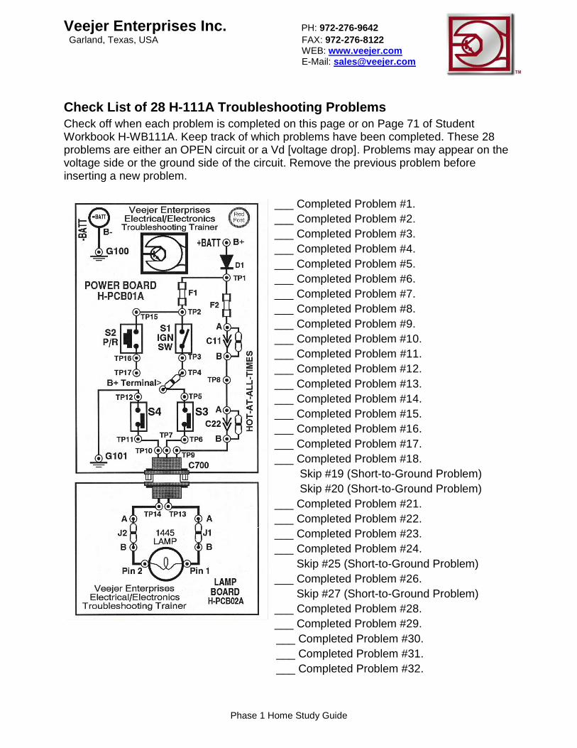
Check List of 28 H-111A Troubleshooting Problems
Check off when each problem is completed on this page or on Page 71 of Student Workbook H-WB111A. Keep track of which problems have been completed. These 28 problems are either an OPEN circuit or a Vd [voltage drop]. Problems may appear on the voltage side or the ground side of the circuit. Remove the previous problem before inserting a new problem.
___ Completed Problem #1.
___ Completed Problem #2.
___ Completed Problem #3.
___ Completed Problem #4.
___ Completed Problem #5.
___ Completed Problem #6.
___ Completed Problem #7.
___ Completed Problem #8.
___ Completed Problem #9.
___ Completed Problem #10.
___ Completed Problem #11.
___ Completed Problem #12.
___ Completed Problem #13.
___ Completed Problem #14.
___ Completed Problem #15.
___ Completed Problem #16.
___ Completed Problem #17.
___ Completed Problem #18.
Skip #19 (Short-to-Ground Problem)
Skip #20 (Short-to-Ground Problem)
___ Completed Problem #21.
___ Completed Problem #22.
___ Completed Problem #23.
___ Completed Problem #24.
Skip #25 (Short-to-Ground Problem)
___ Completed Problem #26.
Skip #27 (Short-to-Ground Problem)
___ Completed Problem #28.
___ Completed Problem #29.
___ Completed Problem #30.
___ Completed Problem #31.
___ Completed Problem #32.
Veejer Enterprises Inc. PH: 972-276-9642
Garland, Texas, USA FAX: 972-276-8122 WEB: www.veejer.com E-Mail: [email protected]
Phase 1 Home Study Guide
After completing the 28 problems consisting of OPEN connections and Vds (voltage
drops) you are ready to tackle short-to-ground problems. You are still working in the
Student Workbook H-WB111A.
___ Workbook H-WB111A read Pages 32 to 36 explaining short-to-ground problems.
___ Workbook H-WB111A read Pages 63 to 66 explaining ohmmeter readings that
indicate a “short is present.”
You are now ready to practice troubleshooting short-to-ground problems.
• UNPLUG THE POWER SUPPLY.
• DISCONNECT THE RED AND BLACK WIRES FROM THE RED/BLACK POSTS.
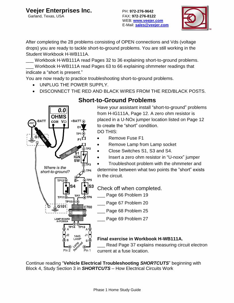
Short-to-Ground Problems Have your assistant install “short-to-ground” problems
from H-IG111A, Page 12. A zero ohm resistor is
placed in a U-NOx jumper location listed on Page 12
to create the “short” condition.
DO THIS:
• Remove Fuse F1
• Remove Lamp from Lamp socket
• Close Switches S1, S3 and S4.
• Insert a zero ohm resistor in “U-noxx” jumper
• Troubleshoot problem with the ohmmeter and
determine between what two points the ”short” exists
in the circuit.
Check off when completed.
___ Page 66 Problem 19
___ Page 67 Problem 20
___ Page 68 Problem 25
___ Page 69 Problem 27
Final exercise in Workbook H-WB111A.
___ Read Page 37 explains measuring circuit electron
current at a fuse location.
Continue reading “Vehicle Electrical Troubleshooting SHORTCUTS” beginning with Block 4, Study Section 3 in SHORTCUTS – How Electrical Circuits Work

Veejer Enterprises Inc. PH: 972-276-9642
Garland, Texas, USA FAX: 972-276-8122 WEB: www.veejer.com E-Mail: [email protected]
Phase 1 Home Study Guide
Block 4
Read Section 3 in SHORTCUTS – How Electrical Circuits Work
Why study electrical circuit principles?
___ Understand Water hoses in a series connection / Hose water current / Electrical
series circuit / The law of electron current in a series circuit
___ Understand Impact of resistance R1
___ Understand Current takes the path of least resistance
___ Understand Measuring electron current in a series circuit
___ Understand Voltage in a series circuit
___ Understand How much should a Vd (Voltage Drop) be?
___ Understand Vd of components in a circuit
___ Understand Law of voltage in a series circuit
___ Understand The voltage drop of the voltage side
___ Understand The voltage drop of the ground side
___ Understand Law of resistance in a series circuit
___ Understand Load resistance
___ Understand Starter Kit H-111 troubleshooting training
___ Understand Two water hoses in parallel
___ Understand Electrical parallel circuit
___ Understand Law of current in parallel circuits
___ Understand Current takes the path of least resistance / Measuring total electron
current in a parallel circuit / Measuring individual parallel branch electron current / Law of
voltage in parallel circuits / Measuring voltage inside a branch / Law of resistance in
parallel circuits / Example of resistors in parallel / Compound circuit Voltage measurement
techniques / Measuring B+ / Measuring Vd of the voltage side Measuring voltage drop of
the ground side / Putting it all together /
H-113 Troubleshooting DC Motor Circuits Troubleshooting Trainer (Studied in Phase 2
Curriculum.)
___ Completed Section 3
___ Answered Review Questions

Veejer Enterprises Inc. PH: 972-276-9642
Garland, Texas, USA FAX: 972-276-8122 WEB: www.veejer.com E-Mail: [email protected]
Phase 1 Home Study Guide
Block 5
Read Section 4 in SHORTCUTS - Quick Troubleshooting Batteries
Introduction to batteries / Battery voltage / What happens in a battery / Battery during
discharge / Battery discharge circuit / Battery changes during discharge / Battery
recharge circuit / The battery during recharge / Testing batteries / Cycle testing electrical
circuits
___ Read about battery voltage test called Open Circuit Voltage (O.C.V.)
Perform this test on some vehicle batteries and/or batteries in storage.
Vehicle ___________________ O.C.V. _______ V %State of Charge ________
Vehicle ___________________ O.C.V. _______ V %State of Charge ________
Vehicle ___________________ O.C.V. _______ V %State of Charge ________
___ Understand when battery O.C.V. is 12.66V
___ Understand when battery O.C.V. suddenly drops down to 10.55V
___ Understand when battery O.C.V. is suddenly drops to almost zero volt
___ Understand when battery O.C.V. is over 13.00V
___ Understand Battery Cranking Voltage Test
Perform the Cranking Voltage Test on some vehicles.
Vehicle ___________________ Cranking Voltage _______ V Ambient Temp ____ºF
Vehicle ___________________ Cranking Voltage _______ V Ambient Temp ____ºF
Vehicle ___________________ Cranking Voltage _______ V Ambient Temp ____ºF
___ Summary of cranking voltage test
___ Understand Battery cranking electron current test
Perform the Cranking Amps Test on some vehicles.
Vehicle ___________________ Cranking Amps _______A Ambient Temp ____ºF
Vehicle ___________________ Cranking Amps _______A Ambient Temp ____ºF
Vehicle ___________________ Cranking Amps _______A Ambient Temp ____ºF
___ Understand Battery Recharge Electron Current Test
Perform Battery Recharge Electron Current Test (Single battery negative cable)
Vehicle _______________ Recharge Amps _______A Time running _____ min.
Vehicle _______________ Recharge Amps _______A Time running _____ min.
Vehicle _______________ Recharge Amps _______A Time running _____ min.
___ Understand Carbon pile battery load test not suitable for service bay diagnostics
Battery bounce-back test (used only in conjunction with carbon pile test)
Determine remaining battery life (compare cranking voltage with ambient temp.)
Overview of 5-Step Battery test procedure / Practice on vehicles and record readings.
___ Completed Section 4
___ Answered Review Questions
Veejer Enterprises Inc. PH: 972-276-9642
Garland, Texas, USA FAX: 972-276-8122 WEB: www.veejer.com E-Mail: [email protected]
Phase 1 Home Study Guide
Block 6
Read Section 5 in SHORTCUTS - Quick Troubleshooting Cranking
Some of these tests repeat from the previous Block 5 on Batteries. That is due to the close interrelationship of the battery and the cranking motor working together. The starter motor is used to test the battery under load. The battery is used to test the performance of the starter motor circuit cranking the engine. Once the individual concepts of battery performance and starter operation are understood separately they can easily combined for an overall test of starter circuit performance as each component does its job. Introduction to cranking circuits / Basic cranking circuit /
___ Understand starter motor current
___ Overview of troubleshooting cranking circuit problems
___ Measure cranking current or starter motor draw
___ Measure battery cranking voltage
___ Understand 3-Step cranking circuit test procedure
___ Understand when starter draw is too high
___ Understand when starter draw is too low
___ Understand if there is a bad connection in the wiring?
___ Understand a resistance problem in the starter motor?
___ Understand how to pinpoint a bad connection or cable on voltage side.
___ Understand how to perform 3 Step QUICK cranking circuit test on a vehicle
Vehicle ___________ Cranking Volts ____ V Cranking Current Test ____ A
Vehicle ___________ Cranking Volts ____ V Cranking Current Test ____ A
Vehicle ___________ Cranking Volts ____ V Cranking Current Test ____ A
___ Understand cranking circuit control
___ Understand testing the solenoid control circuit
___ Understand simple cranking circuit
___ Understand failure to crank
___ Understand cranking control circuit.
Troubleshooting starter relay circuit / A true story.
___ Completed Section 5
___ Answered Review Questions

Veejer Enterprises Inc. PH: 972-276-9642
Garland, Texas, USA FAX: 972-276-8122 WEB: www.veejer.com E-Mail: [email protected]
Phase 1 Home Study Guide
Block 7
Read Section 6 in SHORTCUTS - Quick Troubleshooting Charging
Systems
Introduction to generator/charging systems / Overview of the charging system / Inside a
generator / What a generator does / Interpreting the charging voltage /
___ Understand Three factors that affect the charging voltage
___ Understand Generator voltage tests
___ Understand Generator electron current tests
___ Understand The charging voltage test
___ Understand When charging voltage is too high or too low
___ Understand generator/battery current test
___ Understand Measuring battery recharge electron current
___ Understand Factors that determine battery recharge current
___ Understand How to measure battery recharge current
___ Understand what's good - what's bad
___ Understand Read the DMM correctly
___ Understand Determining if a battery is defective when recharging
___ Try this simple experiment
___ Understand The conclusion of measuring battery recharge current
___ Understand Generator ripple voltage test
___ Understand Lab scope test of generator output
___ Understand Overview of testing vehicle charging system
___ Understand Evaluating charging voltage test results
___ Understand The wrong way to test a generator
___ Understand Two major problems with the generator load test
___ Understand Computer controlled generator
___ Understand How an onboard computer controls the generator
___ Here's the problem
___ Understand Testing resistance of rotor/field winding
___ Understand Hot and cold resistance
___ Understand Evaluating/calculating rotor/field winding condition
___ Understand rotor/field windings may be internally grounded
___ Understand Introduction to PWM (pulse-width-modulation)
___ Understand PWM duty cycle
___ Understand PWM rotor/field winding control
___ Completed Section 6
___ Answered Review Questions

Veejer Enterprises Inc. PH: 972-276-9642
Garland, Texas, USA FAX: 972-276-8122 WEB: www.veejer.com E-Mail: [email protected]
Phase 1 Home Study Guide
Block 8
FIRST THINGS FIRST™ This is a laminated flip-chart that tests a vehicle’s primary electrical system consisting of the battery, primary grounds circuits (engine ground and accessory ground) and the charging system. The first series of voltage tests are performed with a cold engine; then running and then a quick retest after the engine warms up. Entire test sequence consisting of 14 voltage measurements can be accomplished in less than 5 minutes with a little practice. Each test step is explained and illustrated on its own laminated page.
Technicians are going through FIRST THINGS FIRST for the first time. Each test step is fully explained on the left side of the page and an illustration of the DMM test leads connected to the vehicle is shown on the right side of the page for added clarity. These tests will reveal a weak or undercharged battery, a faulty engine or accessory (sheet metal) ground circuit, and a poor performing charging system. Simply follow instructions to proceed through the test sequence. Make paper copies of The Test Results Form printed on the back cover of the flip-chart and record your readings. The Test Results Form may be copied on any copy machine and used to record test results. A copy can be given to the customer. There is a place to paste your business card at the bottom so the customer knows who did the electrical system analysis.
Veejer Enterprises Inc. PH: 972-276-9642
Garland, Texas, USA FAX: 972-276-8122 WEB: www.veejer.com E-Mail: [email protected]
Phase 1 Home Study Guide
Block 9
Study Section 7 in SHORTCUTS – Reading Schematic Diagrams
___ How to read a schematic or “schemation” diagram
___ Understand What a schematic or “schemation” diagram can do
___ Understand What a diagram cannot do
___ Understand “Schemation” of a vehicle's primary electrical system
___ Understand Inventory a circuit diagram
___ Understand Trace the path of electron current
___ Understand Measure the voltage around the circuit
___ Understand Physically trace the circuit lines
___ Completed Exercise 7-3
___ Understand Reading a relay-controlled cooling fan circuit diagram
___ Understand How the circuit works
___ Understand Troubleshooting the circuit on paper
___ Completed Exercise 7-4
___ Understand Reading a relay controlled cranking circuit diagram
___ Understand How the circuit works
___ Understand Troubleshooting the circuit on paper
___ Completed Exercise 7-5
___ Understand Reading a relay controlled horn circuit diagram
___ Understand How the circuit works
___ Understand Troubleshooting the circuit on paper
___ Completed Exercise 7-6
___ Reading a rear compartment relay controlled lid release circuit diagram
___ Understand How the circuit works
___ Understand Troubleshooting the circuit on paper
___ Completed Exercise 7-7
___ Reading a relay controlled window defogger circuit diagram
___ Understand How the circuit works
___ Understand Troubleshooting the circuit on paper
___ Completed Exercise 7-8
___ Understand Reading a relay controlled wiper/washer pump motor circuit diagram
___ Understand How the circuit works
___ Understand Troubleshooting the circuit on paper / Conclusion
Congratulations on completing the “Phase 1 – “Hands-On Vehicle Electrical-Electronics
Troubleshooting Workshop.” May you have great success and make more money,
Vince Fischelli. Contact us for details on studying Phase 2 Workshop training.